

Bellcome KIT.APA.2F0.BLS Datasheet [ml]
BENUTZERHANDBUCH
SET AUDIOTÜRSPRECHANL AGE advanced
2 Familien
Kurt König
Ludwig Wolf
DE
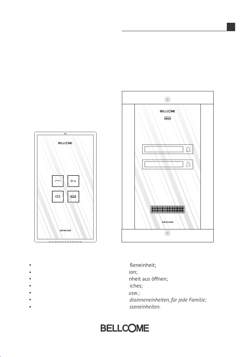
Ruf tätigen mit Hilfe der Ruftasten der Außeneinheit;
Full-duplex Freisprech Audiokommunikation;
Das Zugangstor / die -Tür von der Inneneinheit aus öffnen;
Die Audioüberwachung des Eingangsbereiches;
Optionaler Hilfsbefehl: Autotor, Garagentür usw.;
inneneinheiten, für jede Familie Optional max. 3 parallel angeschlossene Audio ;
einheiten.Optional max. 3 parallel angeschlossene Aussen
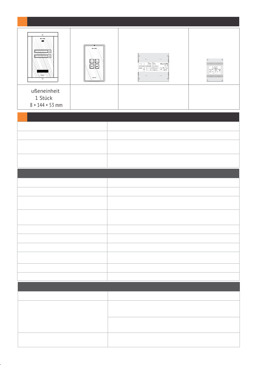
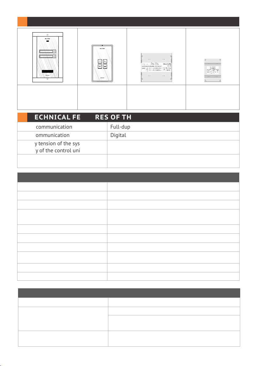
1 INHALT DES SETS
Kurt König
Ludwig Wolf
Außeneinheit
1 Stück
238 × 144 × 53 mm
Inneneinheit
2 Stück
170 × 96 × 30 mm
Stromversorgungseinheit
1 Stück
130 × 141 × 73 mm
2 TECHNISCHE EIGENSCHAFTEN DER ANL AGE
Audiokommunikation
Datenkommunikation
Betriebsspannung der Anlage
(Versorgung aus der Zentaleinheit)
Max. verbrauchter Strom aus dem
230 V Wechselstrom Netz
2.1 Technische Eigenschaften der Außeneinheit
Betriebsspannung
Tastatur
Die Anzeige des/der Namen
der Bewohner(s)
Gehäuse
Montage
Schutzklasse (IP)
Betriebstemperaturbereich
Transport- und
Lagerungstemperaturen
Masse
Gewicht
Full-duplex
Digital
230 V±10% / 50 Hz
0,4 A Wechselstrom
12,0 ... 14,3 V Gleichstrom (stabilisiert)
TOUCH, ständig beleuchtet
Platz für die Namensanzeige mit
Hintergrundbeleuchtung
Aluprofil lackiert; Bildschirm aus Sicherheitsglas,
8 mm stark
Unterputz
IP44
- 30° C ... + 45°C
- 33° C ... + 55° C
238 x 144 x 53 mm
1,3 kg
Verbindungsbox
1 Stück
100 × 71 × 60 mm
2.2 Technische Eigenschaften der Inneneinheiten
Betriebsspannung
Tastatur
Regelung
12,0 .... 14,3 V Gleichstrom (stabilisiert)
TOUCH, 4 Tasten, beleuchtet, bei Betätigung
der Tastatur
Die VO LUMEN-Taste leuchtet ständig ROT,
wenn das Gerät ausgeschaltet ist
- Lautstärkeregelung Audio:
MAX. ST UFE – MIT TELSTUF E – AU SGESCHALTET
2/92

Gehäuse
Montage
Schutzklasse (IP)
Betriebstemperaturbereich
Transport- und
Lagerungstemperaturen
Masse
Gewicht
ABS
Glasbildschirm, 3 mm stark
Aufputz
IP31
0°C ... + 40°C
- 33°C ... + 55°C
171 x 96 x 30 mm
0,4 kg
2.3 Technische Eigenschaften der Stromversorgung
Betriebsspannung
Versorgungsspanung / -strom
innerhalb der Anlage
Gehäuse
Montage
Schutzklasse (IP)
Betriebstemperaturbereich
Transport- und
Lagerungstemperaturen
Masse
Gewicht
230V±10%/50Hz
+14V - GND : +14VGleichstrom (stabilisiert)/
2A Gleichstrom
+ Uv GND : +14VGleichstrom -
-
Ucam
ABS mit Brandschutz
- auf Schiene DIN: TH 35 x 15 oder 35 x 7,5
gemäß DIN46277-3, EN50022, IEC60715
- Aufputz: mit Schrauben A3,5 x 32 und
Dübel ø 6 mm
IP31
0°C ... + 40°C
- 33°C ... + 55°C
130 x 141 x 73 mm
0,4 kg
GND : +14VGleichstrom
0.5AGleichstrom
0.2AGleichstrom
(stabilisiert )/
(stabilisiert )/
2.4 Technische Eigenschaften der Verbindungsbox
Eingang – Ausgang
Ausgang (Derivation)
Gehäuse
Montage
Schutzklasse (IP)
Betriebstemperaturbereich
Transport- und
Lagerungstemperaturen
1
4
ABS
- auf Schiene DIN: TH 35 x 15 oder 35 x 7,5
gemäß DIN46277-3, EN50022, IEC60715
- Aufputz: mit Schrauben und Dübel ø 6 mm
IP31
0°C ... + 40°C
- 33°C ... + 55°C
3/92
Masse
Gewicht
100 x 71 x 60 mm
0,2 kg
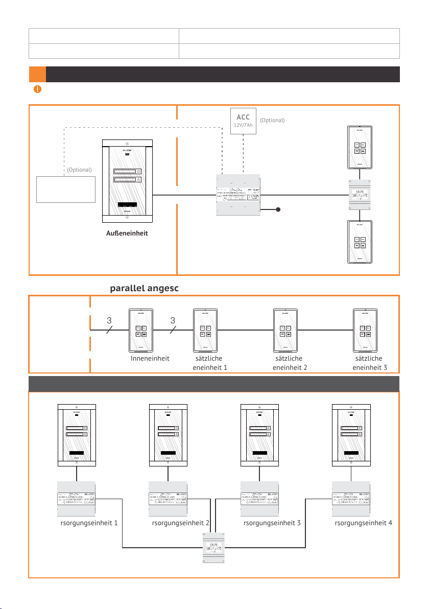
3 BLOC KDIAGRAMM DER ANLAGE
Alle als „optional“ beschriebenen Produkte sind nicht im Lieferumfang erhalten und können
separat erworben werden.
AUSSEN
(Optional)
Elektromagnetisches
Schloss DC/ AC
Kurt König
Ludwig Wolf
Außeneinheit
INNEN
3
/
6
/
Stromversorgungseinheit
Zusätzliche parallel angeschlossene Inneneinheiten (Optional)
ACC
12V/7Ah
2
/
Akku
(Optional)
3
/
Wechselstrom
3
/
230 V
Inneneinheit 1
/
3
/
3
Inneneinheit 2
Von der
Verbindungsbox
3
/
Haupt Inneneinheit
3
/
Zusätzliche
Inneneinheit 1
3
/
Zusätzliche
Inneneinheit 2
3
/
Zusätzliche
Inneneinheit 3
3.1 Blockdiagramm für den parallelen Anschluss von Paneelen (optionell)
Außeneinheit 1 Außeneinheit 2 Außeneinheit 3 Außeneinheit 4
Kurt König
Ludwig Wolf
Stromversorgungseinheit 1 Stromversorgungseinheit 2 Stromversorgungseinheit 3 Stromversorgungseinheit 4
Kurt König
Ludwig Wolf
Verbindungsbox
Kurt König
Ludwig Wolf
Kurt König
Ludwig Wolf
4/92
4
INSTALL ATIO N
4.1 Empfohlene Kabel
Außeneinheit
Stromversorgungseinheit
UTP CAT5e (AWG24) Kabel für Längen von bis zu max. 70 m zwsichen der Außeneinheitund
der Stromversorgung und von 250 m zwischen dem Außeneinheit und der Inneneinheit.
Falls Sie Verkabelungen von mehr als 250 m planen, kontaktieren Sie bitte den Hersteller
für weitere Informationen.
Verbindungsbox
Inneneinheit
Stromversorgungseinheit
Elektromagnetisches Schloss (Optional)
Mehrfaserkabel, flexibel, (Cu) 2 oder 3 x 0,75 mm² für Längen von bis zu max. 50 m oder
(Cu) 2 oder 3 x 1 mm² für Längen von bis zu max. 100 m.
Stromversorgung
230 V Netz Wechselstrom.
Mehradriges Kabel, flexibel, (Cu) 3x0,5 mm² oder 3 x 0,75 mm²
4.2 Sicherheitshinweise für die Montage
ACHTUNG! Der Anschluss an das 230 V / 50 Hz Netz sowie die Wartung der
Zentraleinheit /Stromversorgung darf nur von dafür zugelassenem Personal (autorisierter
Elektriker) ausgeführt werden!
Es wird empfohlen, dass die Zentraleinheit in einem Sicherungskasten montiert wird.
ACHTUNG! EN TFERN EN S IE N IEMALS D IE F RON TABD ECK UNG DER
ST ROMVER SORGUNG! G EFAHR EI NES STROMSCHL AGS!
Für die Montage dürfen nur die Schutzabdeckungen der Anschlusskontakte von
Fachpersonal entfernt werden.
ACHTUNG! Die Versorgung der Zentraleinheit vom 230 V / 50Hz Netz muss unbedingt
über zwei 10 A Automatsicherungen (auf die Phasen- und Nullleiter) erfolgen. Der
Anschluss an den F und N Leiter der Zentraleinheit/Stromversorgung muss über zwei
isolierte Drähte (Cu) mit einem Querschnitt von 0,75 mm² erfolgen.
ACHTUNG! Stellen Sie unbedingt sicher, dass während des Einbaus und des Anschlusses
der Stromversorgung an das 230 V / 50Hz Netz alle Sicherungsautomaten abgeschalten
(bzw. Schraubsicherungen herausgedreht) und damit die Stromzufuhr unterbrochen ist.
Prüfen Sie zur Sicherheit mit Hilfe eines Messgerätes ob alle Leiter Strom- bzw.
Spannungslos sind (POWE R OFF).
Die Erdungsverbindung (Cu) 0,75 mm2 muss UNBEDIN GT zwischen dem Erdungsleiter
des Schaltschrankes und dem Erdungsleiter der Stromversorgung hergestellt
werden.
WI CHT IG! Vor dem Einschalten der Netzsicherungen für die Stromversorgungseinheit,
überprüfen Sie die Richtigkeit der Anschlüsse. Prüfen sie diese visuell und auch mit Hilfe
eines Ohmmeters.
WI CHT IG! Montieren sie unbedingt wieder die Abdeckungen der Anschlüsse an der
Stromversorgung bevor Sie die Versorgungssicherungen(230V / 50Hz) einschalten.
ACHTEN S IE auf die richtige Polarität der Leiter während des Anschlusses eines Akkus
(max. 7 Ah) an die Zentraleinheit/Stromversorgung. Das Vertauschen der Leiter führt zu
Akkubeschädigungen. Der Einbau und Anschluss des Akkus darf nur von dafür
zugelassenem Personal ausgeführt werden.
BE RÜH REN SIE N IEM ALS Drähte welche aus der Stromversogungseinheit/
Zentraleinheit ragen. Schalten Sie die Sicherungen (10 A) vom Phasen- und Nullleiter der
Zentraleinheit/Stromversorgung ab.
ACHTUNG! Versorgen Sie die Komponenten der Anlage (Außeneinheit, Inneneinheit,
Verbindungsbox, oder andere Zusatzgeräte) NIEMAL S mit einer Spannung höher als 15 V
Gleichstrom oder mit Wechselspannung direkt (230 V / 50 Hz). GEFAHR EI NES
EL EKTROSCHOCK S und Zerstörung der Anlage.
5/92
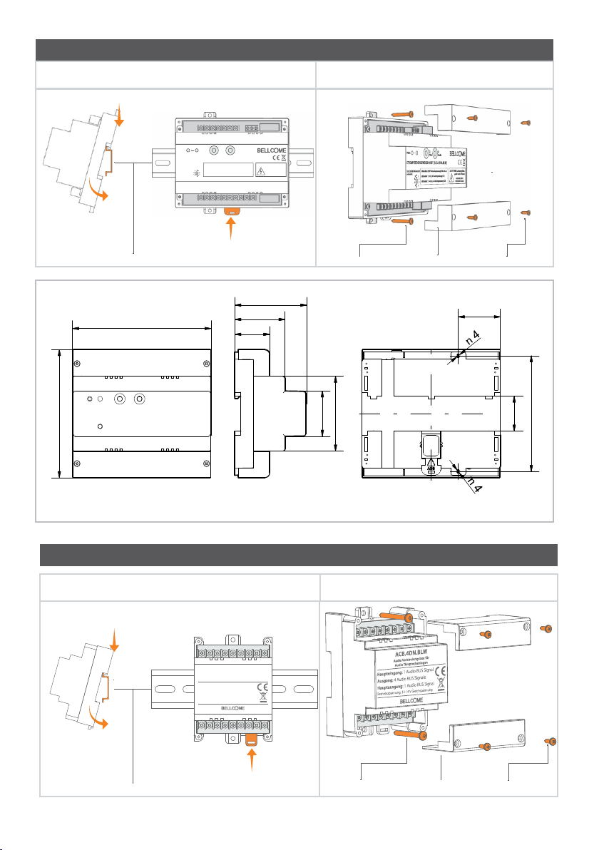
4.3 Der Einbau der Stromversorgung
Einbau auf einer DIN Schiene
Aufputz
1
S2
PROG
VideoS1Audio
STROMVERSORGUNGSEINHEIT (SCU.VDN.BL W)
EINGANG: 230V Wechselspannung 50Hz, 0.4A
SCHLOSSÖFFNUNGSZEIT
(sekunden)
1
2
10
AUSGANG 1: 14V, 2A Gleichspannung (S1)
3
9
AUSGANG 2: 14V, 0.5A Gleichspannung (S2)
4
8
7
5
6
ACHTUNG! Lebensgefahr,
gerät nicht öffnen!
GEFAHR EINES
STROMSCHLAGS!
2
3
DI N Schiene
Befestigungsklammern
73,0
140,7
51,0
35,5
130,0
Vorderansicht
Seitenansicht
Der Akku wird an die Leiter der Stromversorgung nach der Inbetriebnahme der Anlage angeschlossen.
A3,5 × 32 Schraube (2 St.) B2,9 × 13 Schraube (4 St.)Schutzdeckel (2 St.)
46,0
76,0
Hinteransicht
42,8
35,5
117,5
4.4 Der Einbau der Verbindungsbox
Einbau auf einer DIN Schiene
1
ACB.4DN.BLW
Audio Verbindungsbox für
Audio Türsprechanlagen
Haupteingang: 1 Audio BUS Signal
Ausgang: 4 Audio BUS Signale
Hauptausgang: 1 Audio BUS Signal
Betriebsspannung: 12-14 V Gleichspannung
2
3
BefestigungsklammernDI N Schiene
Aufputz
A3,5 × 32 Schraube (2 St.) B2,9 × 13 Schraube (4 St.)Schutzdeckel (2 St.)
6/92
Vorderansicht
Seitenansicht Hinteransicht
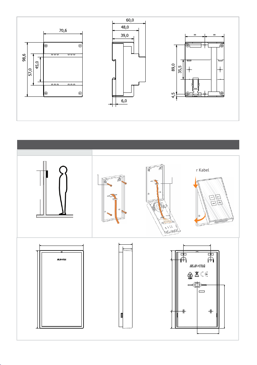
4.5 Der Einbau der Inneneinheiten
Bevor Sie anfangen...
155 cm
Die Inneneinheit wird auf einer Höfe
von 155 cm (empfohlene Höhe) montiert.
96,5
171,5
Vorderansicht Seitenansicht
A3,5 × 35(32) Schraube
(4 St.)
18 cm
Die Kabellänge
(von der Wand)
29,5
21
Befestigungsteil –
Führungsteil für Kabel
1
2
60,0
20,5
113,5
37,5
48,2
Hinteransicht
95,7
7/92

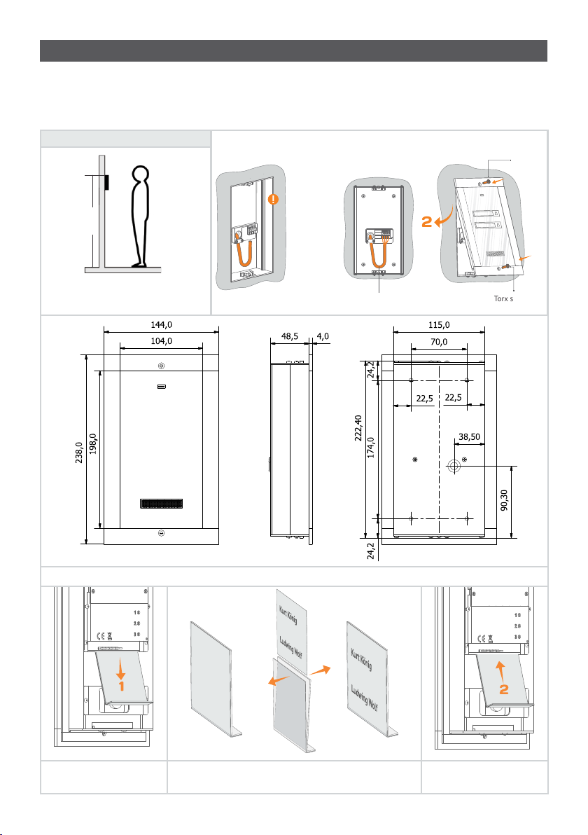
4.6 Der Einbau der Außeneinheit
Die Außeneinheit wird beim Grundstück- oder Hauseingang, auf die Halterung, die dem
Zugangstor / -Tür am nächsten liegt, auf einer Höhe von ca. 1,70 m (Oberkante) vom Boden
montiert, so dass sie vor Witterungseinflüssen geschützt ist. Das Zählen von AußeneinheitTastatur ist von kieloben, der erste Taste, der Adresse 1 bedeutet.
Bevor Sie anfangen...
170 cm
-
5
c
-5 cm
m
Der Gehäuserahmen
muss bündig mit
der Wand sein.
2
1
Torx
Schraube
Die Außeneinheitl wird beim
Hauseingang auf die Halterung, die der
Zugangstür am nächsten liegt, montiert
Vorderansicht
Individualisierung mit den Bewohnernamen
20cm
Kabellänge
Seitenansicht
Türtelefonkabel
3
Torx Schraube
Hinteransicht
Die Kunststoffhalterung aus
dem Tastaturmodul wird
entfernt.
Das individualisierte Papier wird in die
Kunststoffhalterung eingefügt.
Die Kunststoffhalterung aus
dem Tastaturmodul wird
nochmals eingefügt.
8/92
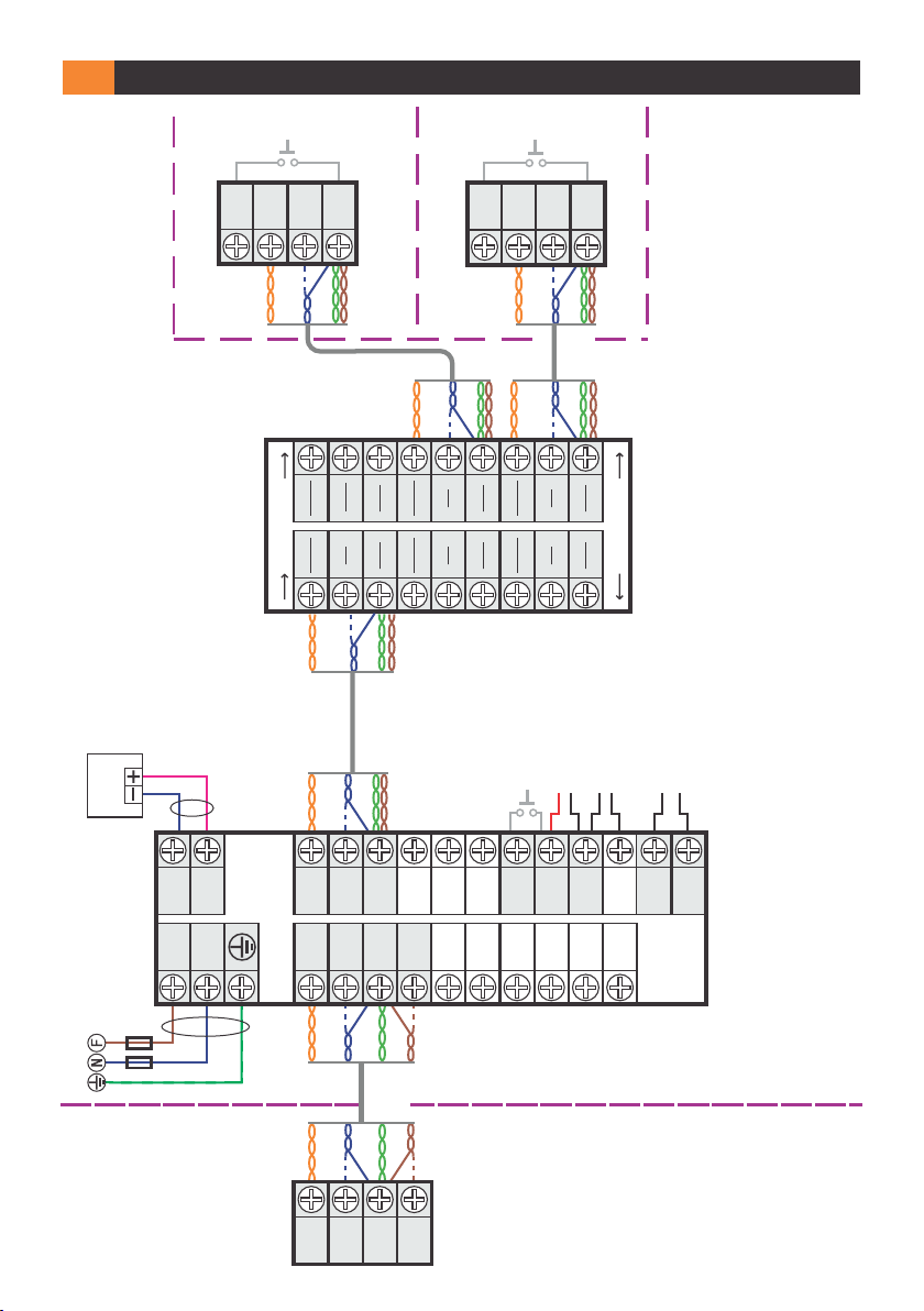
DAS ANSCH L USSSCHEMATA
5
Türklingel
CD
+14V
Dbl
FAMIL IE 1
ORANGE
Akku
ACC
12V/7 Ah
2 x 0,5 mm²
Kabel
OUT
IN
BLAU
ORANGE
GND
GRÜN
BRAUN
(AWG 24)
UTP CAT 5e
CD
GND
OUT
OUT
+14V
CD
IN
IN
ORANGE
GND
BLAU
GRÜN
(AWG 24)
UTP CAT 5e
GRÜN
BLAU
+14V
Inneneinheit 1
OUT
IN
BRAUN
ORANGE
BRAUN
FAMIL IE 2
BLAU
3
CD
+14V
1
CD
+14V
Türklingel
CD
+14V
Dbl
ORANGE
GRÜN
BRAUN
3
3
GND
+14V
1
1
GND
+14V
ORANGE
4
2
BLAU
BLAU
CD
CD
GND
Inneneinheit 2
BRAUN
GRÜN
(AWG 24)
UTP CAT 5e
GRÜN
4
4
GND
2
2
GND
BRAUN
APTAPT
AC B.4DN.xxy
Verbindungsbox
(Optional)
Türöffnungsknopf
oder
Schloss Wechselstrom
Schloss Gleichstrom
AUX Befehl
-ACC
F
+ACC
N
LC
+Uv
GND
+14V
CD OUT
CD IN
+14V
GNDPVin 1
Vout
BUT
GNV
OUT
GNV 1
GNV 2
Vin 2
LA/C
Ucam
LA
GND
AUX 2
AUX 1
Stromversorgung
Elektroschaltschrank
2x Sig. 10A
230 V a.c./50Hz
Kabel
3 x 0,75 mm²
ORANGE
ORANGE
BLAU
GRÜN
BRAUN
IN NE RH AL B
DE S
(AWG 24)
UTP CAT 5e
BRAUN
GRÜN
BLAU
GE BÄ UD ES
DE S
GE BÄ UD ES
GND
P
APE.3S0.xxy
APE.3F0.xxy
Außeneinheit
CD
+14 V
AU SS ER HA LB
9/92
5.1 Der Einbau des elektromagnetischen Schlosses (optional)
G
N
D
L
A
A
UX
2
A
UX 1
Gleichstrom
2 x 0.75 mm²
BUT
LC
LA/C
LA
Stromversorgungseinheit
Kabel
LC1
LC2
Gleichstrom
elektromagnetisches Schloss
Die Zentraleinheit/ Stromversorgung kann
Strom von max. 1 A für die Versorgung des
Schlosses liefern.
Auf dem LC - Leiter der Zentraleinheit wird
die Spannung von +14 V Gleichstrom angezeigt.
Der Anschluss eines Befehlknopfes für das
Schloss vom Inneren des Gebäudes erfolgt von
den BUT und LC Leitern der Zentraleinheit.
Trafo.
230 V
wechselstrom
Stromversorgungseinheit
Wechselstrom
12 V
gleichstrom
BUT
LC
LA/C
LA
elektromagnetisches Schloss
5.2 Der Einbau des Hilfsbefehl (optional)
2 x 0.75 mm²
Kabel
Wechselstrom
Relaiskontakt
AUX Befehl
(automation)
maximale Schaltstrom: 1.5 A
6
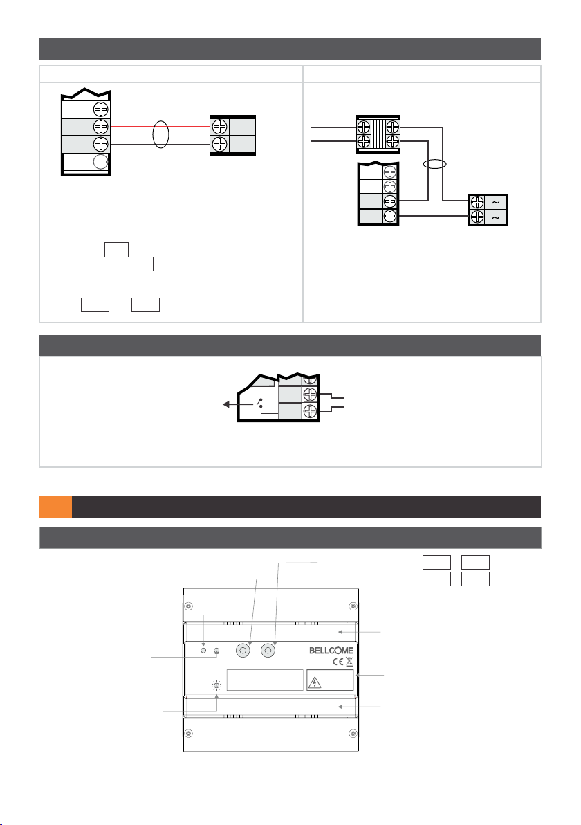
DIE INBETR IEBNAHME DER ANLAGE
6.1 Die Beschreibung der Stromversorgungseinheit
Die Stromversorgung umfasst:
*PROG. : Programmierungsknopf
Rote LE D für die
Programmierung =
Einbaufehler
PROG
STROMVERS ORGUNGSEINH EIT (SCU.VDN.BLW)
SCHLOSSÖFFNUNGSZEIT
(sekunden)
TI ME:
Die Zeitanpassung des Schlosses
* Das System verlangt Programmierung nicht.
Dieser Knopf wird verwendet, nur wenn Sie zusätzliche Inneneiheiten oder Außeneinheiten installieren.
S2
VideoS1Audio
EINGANG: 230V Wechselspannung 50Hz, 0.4A
1
2
10
AUSGANG 1: 14V, 2A Gleichspannung (S1)
3
9
AUSGANG 2: 14V, 0.5A Gleichspannung (S2)
4
8
7
5
6
S1: Audioversorgung +14V - GND
S2: Videoversorgung +Uv - GND
ACHTUNG! Lebensgefahr,
gerät nicht öffnen!
GEFAHR EINES
STROMSCHLAGS!
Schutzabdeckungen für Anschlüsse
Frontabdeckung
Schutzabdeckungen für Anschlüsse
10/92
6.2 Die Überprüfung der Anschlüsse innerhalb der Anlage und der
Anschluss der Stromversorgungseinheit
Überprüfen Sie die Richtigkeit der Anschlüsse innerhalb der Anlage!
Der +14V , GND , CD Empfang ist für alle Bestanteile der Anlage gemeinsam.
Ein Kurzschluss dazwischen führt zu Beschädigungen der gesamten Anlage.
Mit Hilfe eines Ohmmeters wird überprüft dass es keinen Kurzschluss in der Anlage gibt.
Schliessen Sie die Zentraleinheit/Stromversorgung an das 230 V Wechselstrom Netz an, indem Sie die zwei
10 A Automatsicherungen, die auf dem Phasen- und Nulleiter eingebaut sind mit der
Zentraleinheit/Stromversorgung verbinden. Als Option kann der Akku an die +ACC und –ACC Leiter
der Zentraleinheit eingebaut werden.
ACHTEN S IE auf die Polarität des Akkus!
Überprüfen Sie die Betriebsspannung von den Leitern der Zentraleinheit mit den unten angegeben Werte
(verwenden Sie dafür einen Spannungsmesser für Gleichstrom).
Die bei den Leitern der Stromversorgunseinhei gemessenen Spannungen: +14V – GND /13,8 …
14,3Vd.c.
Die Spannung +Uv – GND /13,5 … 14,3Vd.c. wird nicht verwendet.
Die bei den Leitern des Außeneinheit und bei den Leitern des Gerätes gemessenen Spannungen. + 14V
- GND mind. 12 V gleichstrom.
6.3 Die Betriebs- und Regelungsüberprüfung
Während des Anrufes und des Gesprächs muss überprüft werden, ob die Betriebsspannung +14V –
GN D und +Uv – GND mehr als 12,0 V beträgt.
Überprüfen Sie die Funktion von Außeneinheit und Inneneinheit wie: Anruf, Gespräch, Zugang,
Audioüberwachung. Die Anlage wird vom Hersteller aus einem Audio Gesichtspunkt für Standard
Betriebsbedingungen geregelt.
Regelung der Lautstärke an der Inneneinheit:
Indem die VO LU ME N Taste mehrmals gedrückt wird, kann die Lautstärke Mehrstufig verändert werden:
Ausgeschaltet = rote LED, Mittel = weissrote LED, Maximum = weisse LED.
Nach der Überprüfung, regeln Sie die Inneneinheit auf maximales VOLUMEN (WEISSE LED).
6.4 Reparieren
Alle Arbeiten an der Anlage dürfen nur von einem Fachmann durchgeführt werden und nur dann, nachdem sie
vom Versorgungsnetz von 230 V Wechselstrom (die Sicherungen von den Phasen- und Nullleitern werden
ausgeschaltet) und vom Akku (der +ACC-Leiter wird entfernt) getrennt wurde.
Lfd.
Nr.
0
Problem Signalisierung
Die Anlage läuft richtig
Stromversorgung:
S1: grün
S2: grün
PROG:
Mögliche Ursachen
Lösungen
11/92
Die Anlage läuft nicht
(Stromversorgungseinheit
1
ohne Akku)
Die Anlage läuft nicht
(Stromversorgungseinheit
2
ohne Akku)
Es kann kein RUF
3
getätigt werden
Es kann kein RUF
4
getätigt werden
Die Anlage funktioniert
(Stromversorgungseinhe
5
itmit Akku)
Stromversorgung:
S1:
S2:
PROG:
Stromversorgung:
S1: blinklicht – grün
S2:
PROG:
Stromversorgung:
S1: grün
S2: grün
PROG:
Inneneinheit:
Die Tastatur
funktioniert nicht, man
kann keine Anrufe
entgegennehmen.
Außeneinheit zeigt
eine Fehlermeldung
an.
Stromversorgung:
S1: grün
S2: grün
PROG: blinklicht – rot
Inneneinheit:
Die Tastatur
funktioniert nicht,
man kann keine
Anrufe
entgegennehmen.
Außeneinheit zeigt
eine Fehlermeldung
an
Stromversorgung:
S1: Blinklicht rot –
grün
S2: grün
PROG:
Keine Spannung vom
230 V Wechselstrom
Netz.
Kurzschluss in der
Anlage zwischen +14V
und GND
Anschlußmangel
CD an die
Inneneinheitsleiter oder
Draht CD unterbrochen
bis zu den
Inneneinheitsleitern.
Kurzschluss zwischen
dem CD und GND
Anschluss, +14V .
Der Akku wird geladen
Die 10 A Sicherungen im
Sicherungskasten und die 1
und 1,6 A Sicherungen vom
Stromversorgungseingang
werden überprüft.
Überprüfen der
Kabelverbindungen.
Ursachen für den
Kurzschluss finden und
beheben.
Beheben Sie die Ursache
und schalten Sie die Anlage
nochmals ein.
Stellens Sie die nötigen
Anchlüsse her CD an die
Inneneinheit oder es wird
die Kontinuität des CD
Drahtes von der
Stromversorgungseinheit
zu der Inneneinheit
überprüft.
Der Kurzschluss wird (ggf.)
entfernt.
OK
Die Anlage
6
funktioniert
(Stromversorgungseinheit
mit Akku)
Stromversorgung:
S1: Blinklicht rot –
grün
S2: grün
PROG:
Akkustisches Signal
Defekter Akku oder er
ist leer.
Tauchen Sie den Akku aus
12/92
Die Anlage
funktioniert
7
(Stromversorgungseinheit
mit Akku)
VERWENDUNG
7
Stromversorgung:
S1: rot
S2:
PROG:
Keine Spannung
vom 230 V
Wechselstromnetz.
Die Anlage wird aus
dem Akku versorgt.
7.1 Sicherheitseinweisungen bei der Verwendung
Schlagen Sie nicht mit harten Gegenstände auf die Glasoberfläche!
Bei Sprüngen im Glas, berühren Sie das Produkt NICHT!
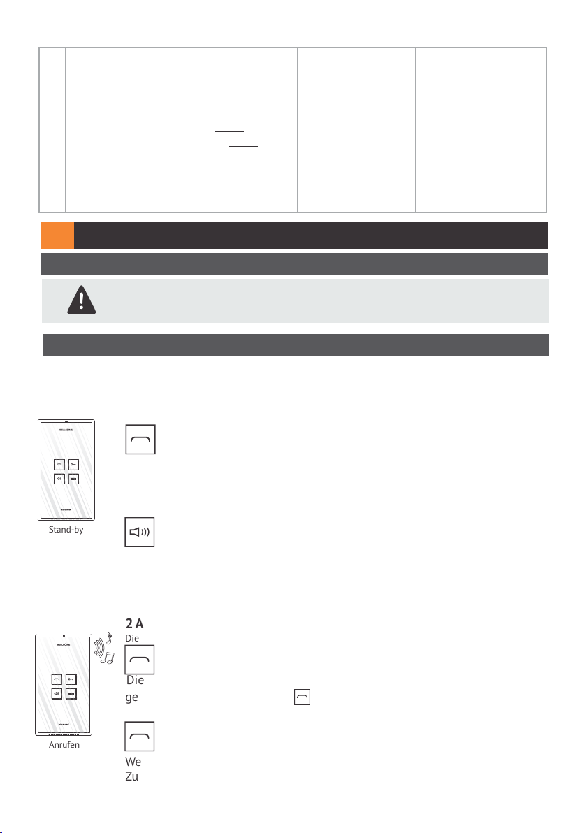
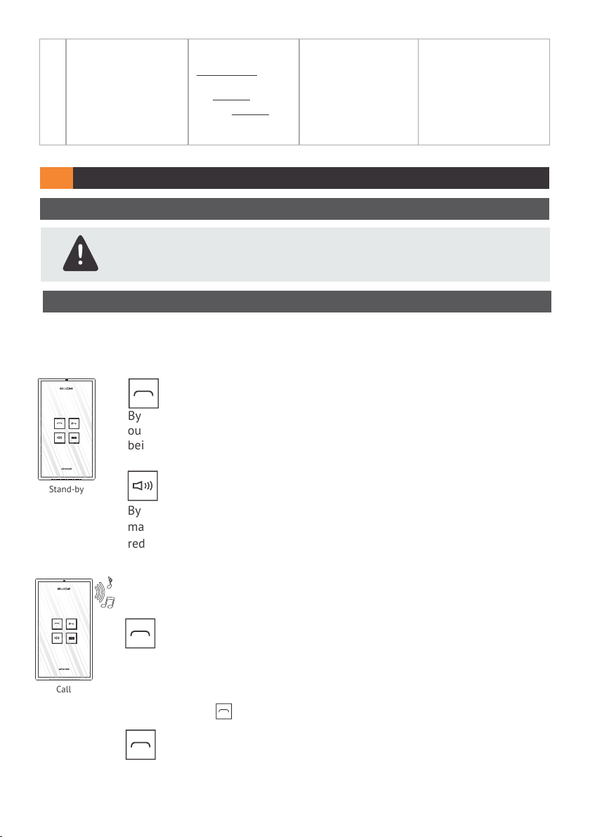
7.2 Die Verwendung der Inneneinheiten
1 STAND-BY
Die Tastatur ist aus.
Bei der ersten Berührung wird die Tastatur eingeschalten, die Inneneinheit kann
die nächsten Befehle erhalten:
AUDIOÜBERWACHUNG
Die Überwachungsdauer: 10 sec.
Indem eine Taste berührt wird, können Sie das was im Eingangsbereich, d.h. vor
der Außeneinheit passiert, hören. Die Überwachung ist nicht möglich wenn eine
andere Inneneinheit eingeschaltet wird oder ist, entweder während des
Gesprächs oder während die Überwachung an ist.
Stand-by
VOLUMENREGELUNG ODER
"INNENEINHEIT AUS”
Indem diese Taste mehrmals berührt wird, findet man drei Volumenstufen:
Maximum (weisse LED), Mittel (weisse-rote LED) und AUS (rote LED). Die rote
LED wird ständig ein sein, bis die Taste nochmals gedruckt wird.
Die 10 A Sicherungen
aus dem
Elektroschaltschrank und
die 1 und 1,6 A
Sicherungen vom
Eingang der
Stromversorgungseinheit
werden überprüft.
Die Kontinuität der
Versorgungskabel wird
überprüft.
Anrufen
2 ANRUFEN UND SPRECHEN
Die Anrufzeit: max. 1 min
ANTWORTEN
Die Sprechzeit: max. 2 min.
Die LED der Taste blinkt . Indem die Taste berührt wird, wird die Kommunikation
gestartet. Berühren Sie die Taste während des Gesprächs nicht.
GESPRÄCH BEENDEN
OHNE DASS MAN ZUGANG GEWÄHRT!
Wenn man die Taste nochmals berührt, wird das Gespräch beendet, ohne dass
Zugang erteilt wurde, die Inneneinheit schaltet wieder in Stand-by.
13/92

3 ZUGANG
ZUGANG UND
GESPRÄCH BEENDEN!
Nach dem Befehl ist das Schloss für eine Zeitspanne von 1 ... 10 sec. nicht
gesperrt, damit die Besucher herein kommen können.
// Wenn Sie die Taste nicht im Vorfeld gedrückt haben, kann kein Zugang
Diskussion
gewährt werden.
4 AUX BEFEHL
HILFSBEFEHL
Unabhängig vom Inneneinheitstand: Überwachung, Anruf oder Ruf, diese Taste
kann eine an die Anlage angeschlossene Automatisierung einschalten: z.B.
Zufahrts- oder Garagentor, ein Beleuchtungssystem usw.
7.3 Die Verwendung der Außeneinheit
1 STAND-BY
Die Anruftaste und die Bewohnernamen sind ständig beleuchtet.
2 ANRUFEN UND SPRECHEN
Kurt König
Ludwig Wolf
Die Anrufzeit: max. 1 min.
Die Diskussionszeit: max. 2 min.
Berühren Sie die Taste.
Der Anruf wird akustisch signalisiert.
Der Anruf wird beendet wenn Sie die Taste nochmals berühren. Wenn der
Besitzer nicht antwortet, wird das Gespräch umgeschaltet.
Wenn man den Zugang gewährt, sendet die Außeneinheit ein akustisches Signal
und das Schloss wird max. 10 Sekunden entspert. Wenn der Benutzer nicht
antwortet, wird die Außeneinheit nach einer Minute wieder in Stand-by
geschalten.
WARTUNG8
Die Außeneinheit muss vor Korrosionsmitteln, Anstrich und mechanischen Schocks geschützt
werden. Die Inneneinheit muss vor Wasser, Anstrich oder weiteren flüssigen Mitteln,
mechanischen Schocks, Dampf, Staub usw. geschützt werden.
Die Bestandteile der Anlage können mit Hilfe eines weichen Baumwollenlappen gereinigt
werden.
Der Akku (optional), der in die Stromversorgungseinheit angeschlossen wird, wird nach seinem
Ablaufdatum ggf. Beschädigung entfernt. Die Zentraleinheit stellt die Akkubeladung solange
der Akku nicht defekt ist, sicher. Der Akkustand wird von den LED-S1 Signalisierungen und von
den akustischen Signale bei einer Beschädigung angezeigt.
14/92

9
GEWÄHRLEISTUNG
Es wird eine Gewährleistung von drei Jahren nach dem Ankaufstag anhand des
Ankaufsnachweises gewährt, sowie auch vorausgesetzt, dass die Anlage gemäß dem
Handbuch verwendet wird.
GEWÄHRLEISTUNG WIRD IN FOLGENDEN FÄLLEN NICHT GEWÄHRT: nicht
entsprechender Einbau und Verwendung, absichtliche Beschädigungen, Diebstahl,
Brand, Erdbeben, Einstellungen, die vom dafür nicht zugelassenen Personal ausgeführt
wurden, wenn die Bestandteile der Anlage bei Renovierungsarbeiten nicht geschützt
werden.
Die BELLCOME Anlagen für Ein- und Mehrfamilienhäuser sind gemäß den gültigen EU-Vorschriften
hergestellt und sind gemäß dem EG-Beschilderungsverfahren beschildert.
10
HERGESTELLT FÜR
ELECTRA Building Communications GmbH
Parkring 10, Liebenberggasse 7
1010 Wien – Österreich
Telefon +43 1 516 33 – 3817 | Telefax + 43 1 516 33 – 3000
office@electra-automation.at | www.electra-automation.at
Made in EU
15/9201.2014

USER MANUAL
KIT Audio DOOR PHONE advanced
2 families
EN
Kurt König
Ludwig Wolf
Call from the outdoor panel keys;
Full duplex hands-free audio communication;
Command of the access gate/door opening from the interior terminal;
Audio monitoring of the entrance of the property, by the inhabitant;
Optional auxiliary command: auto access, garage door, etc;
Optional maximum 3 audio terminals in parallel, for each family;
.Optional maximum 3 outdoor panels in parallel
1 KIT COMPONENTS
Kurt König
Ludwig Wolf
Outdoor panel
1 pc.
238 × 144 × 53 mm
Terminal
2 pcs.
170 × 96 × 30 mm
Supply control unit
1 .pc
130 × 141 × 73 mm
2 TECHNICAL FEATURES OF THE SYSTEM
Audio communication
Data communication
Supply tension of the system
(supply of the control unit)
Maximum power expenditure from
the 230 V a.c. network
2.1 Technical features of the outdoor audio panel
Supply tension
Keyboard
Display of the inhabitant's name
Case
Mounting
Casing protection level (IP)
Operating temperature range
Transport and storage temperature
range
Dimensions
Weight
Full-duplex
Digital
230 V±10% / 50 Hz
0,4 A a.c.
12,0 ... 14,3 Vd.c. (stabilized)
TOUCH type, permanently backlit
Backlit name space
Aluminum profile painted in electrostatic field;
Secured glass screen, 8 mm thick
Flush
IP44
- 30° C ... + 45°C
- 33° C ... + 55° C
238 x 144 x 53 mm
1,3 kg
Audio connection
box - 1 pc.
100 × 71 × 60 mm
2.2 Technical features of the audio terminals
Supply tension
Keyboard
Audio adjustments
12,0 ... 14,3 Vd.c. (stabilized)
TOUCH type, 4 keys, backlit on touch
Permanent RED signaling of the VOLUM E key if the
terminal is turned off.
Audio communication volume: MAXI MUM LEVEL –
MEDIUM LEV EL – TURN ED OFF
Case
Mounting
Casing protection level (IP)
Operating temperature range
Range of transport and storage
temperatures
Dimensions
Weight
ABS
Glass screen, 3 mm thick
Surface
IP31
0°C ... + 40°C
- 33°C ... + 55°C
171 x 96 x 30 mm
0,4 kg
2.3 Technical features of the supply control unit
Supply tension
Generated power tensions/
power capability
Case
Mounting
Casing protection level (IP)
Operating temperature range
Range of transport and storage
temperatures
Dimensions
Weight
230V±10%/50Hz
+14V – GND : +14Vd.c. (stabilised) / 2Ad.c.
+Uv – GND : +14Vd.c. (stabilised) / 0,5Ad.c.
Ucam – GND : +12Vd.c. (stabilised) / 0.2 Ad.c.
Fireproof ABS
On DIN rail: TH 35 x 15 or 35 x 7,5 in compliance
with DIN46277-3, EN50022, IEC60715
Surface: with A3,5 x 32 plastic screws and ø 6 mm pins
IP31
0°C ... + 40°C
- 33°C ... + 55°C
130 x 141 x 73 mm
0,4 kg
2.4 Technical features of the audio connection box
Main input – output
Branch
Case
Mounting
Casing protection level (IP)
Operating temperature range
Range of transport and storage
temperatures
Dimensions
Weight
1
4
ABS
On DIN rail: TH 35 x 15 or 35 x 7,5 in compliance
with DIN46277-3, EN50022, IEC60715
Surface: with A3,5 x 32 plastic screws and ø 6 mm pins
IP31
0°C ... + 40°C
- 33°C ... + 55°C
100 x 71 x 60 mm
0,2 kg
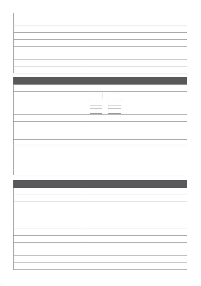
3 BLOC K DIAGRAM OF THE SYSTE M
All additional products are sold separately.
OUTDOOR
(Optional)
Electromagnetic
lock DC / A C
Kurt König
Ludwing Wolf
Panel
INDOOR
3
/
6
/
Additional terminals in parallel (optional)
From the audio
connection box
3
/
Main terminal
3
/
Additional terminal 1 Additional terminal 2 Additional terminal 3
ACC
12V/7Ah
2
/
Supply control unit
3
/
(Optional)
3
/
3
/
230 Va.c.
3
/
Terminal 1
/
3
/
3
Terminal 2
3.1 Block diagram of the connection of additional outdoor panels (optional)
Panel 1 Panel 2 Panel 3 Panel 4
Kurt König
Ludwig Wolf
Supply control unit 1 Supply control unit 2 Supply control unit 3 Supply control unit 4
Kurt König
Ludwig Wolf
connection box
Kurt König
Ludwig Wolf
Kurt König
Ludwig Wolf

4
INSTALLATION
4.1 Recommended cables
Outdoor panel Supply control unit
UTP CAT5e (AWG24) cable for distances of maximum 70 m between the outdoor panel and
the supply control unit and 250m between the outdoor panel and the audio terminal.
For distances greater than 250 m, please request additional information from the producer.
Audio connection box Audio terminal
Supply control unit
Electromagnetic lock (optional)
Flexible, multistrand cable, (Cu) 2 or 3 x 0,75 mm² for distances of maximum 50 m or
(Cu) 2 or 3 x 1 mm² for distances of maximum 100 m.
Supply control unit
230 V a.c. network
Flexible, multistrand cable, (Cu) 3 x 0,75 mm²
4.2 Safety instructions for installation
ATTENTION! The installation, the connection to the 230V/50 Hz network and
the maintenance of the SCU supply control unit will only be carried out by
authorized personnel!
The installation of the supply control unit is recommended to be made within
an electrical panel.
ATTENTION! DO NOT UNFASTEN TH E F RONT L ID! DANGER OF
EL ECTRIC S HO CK!
Only the protection lids of the connections can be unfastened.
ATTENTION! It is mandatory for the supply of the supply control unit from
the 230 V/50Hz network to be made through two automatic fuses of 10 A (on
phase and null). The connection of the F and N hubs of the supply control unit
will be made through two isolated (Cu) wires, with a section of 0,75mm².
ATTENTION! During the installation, connection of the supply control unit at
the 230 V/50Hz network and during service, the safety fuses from the panel
must be opened (POWE R O FF).
The connection of the (Cu) 0,75mm² grounding wire between the grounding
hub of the electrical panel and the grounding hub of the supply control
unit is MANDATORY.
IMPO RTANT! Before connecting the supply control unit's supply fuses, check
the precision of the connections in the system. Check both visually, and by
measurement with an ohmmeter.
IMPO RTANT! Install the protection lids of the supply control unit's
connections before connecting the 2 supply fuses (230V/50Hz).
PAY ATTENTION to the polarity of the hubs when connecting them to the
supply control unit of a buffer accumulator (max. 7 Ah). The inversion of the
hubs leads to the failure of the accumulator. The installation and connection of
the accumulator will be carried out by authorized personnel.
DO NOT TOU CH the wires exiting from the connectors and the hubs of the
control supply unit. Disconnect the fuses (10 A) from the supply's phase and
null of the supply control unit.
ATT EN TI ON! Do not supply components of the installation separately
(outdoor panel, connection boxes, terminals etc.) at tensions higher than
15Vd.c. or directly from the network (230V/50Hz). DAN GE R O F E LE CTRIC
SH OC K and of the door phone system's destruction.
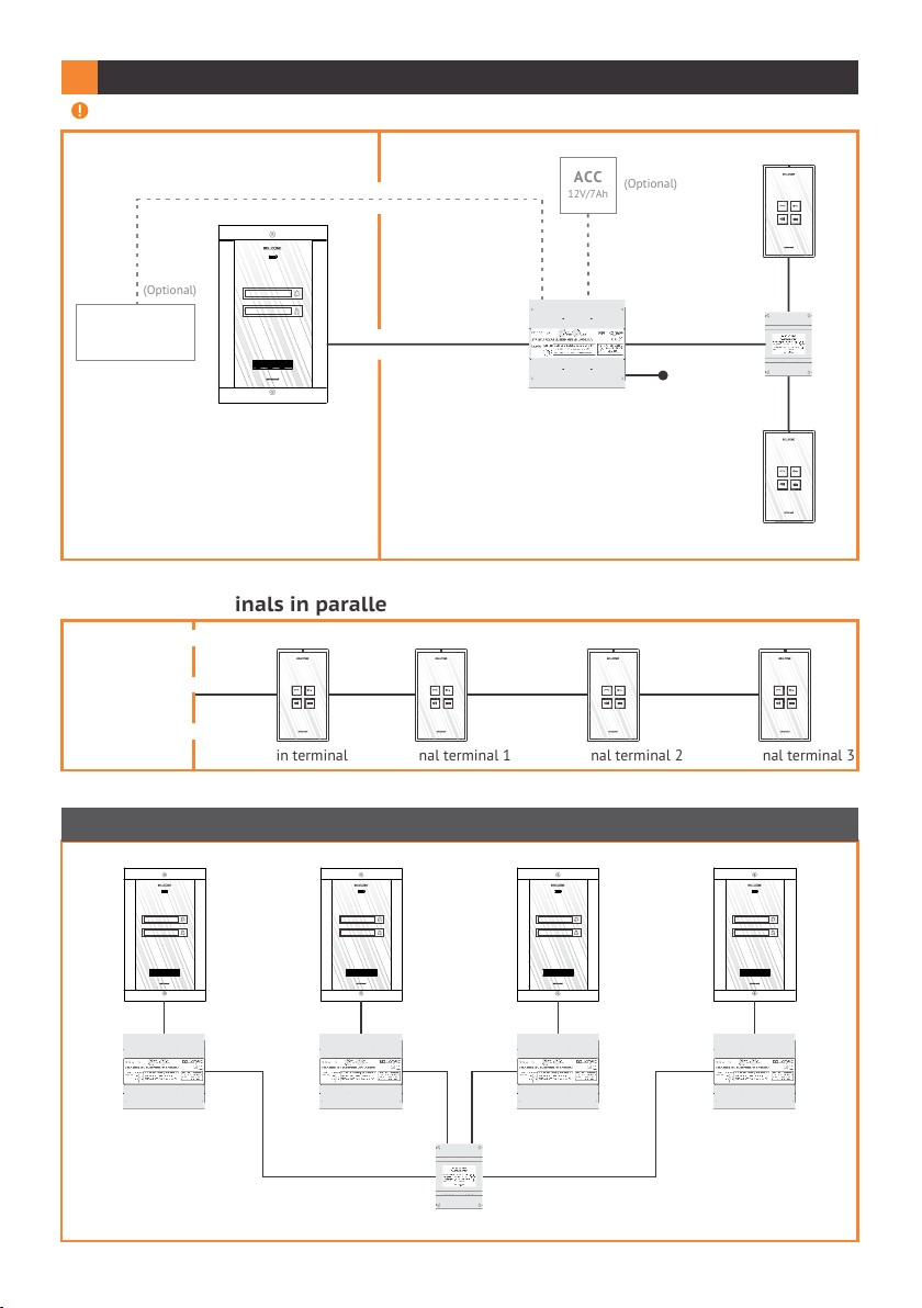
4.3 Installation of the supply control unit
DIN rail mounting
Wall mounting
1
S2
PROG
VideoS1Audio
STROMVERSORGUNGSEINHEIT (SCU.VDN.BL W)
EINGANG: 230V Wechselspannung 50Hz, 0.4A
SCHLOSSÖFFNUNGSZEIT
(sekunden)
1
2
10
AUSGANG 1: 14V, 2A Gleichspannung (S1)
3
9
AUSGANG 2: 14V, 0.5A Gleichspannung (S2)
4
8
7
5
6
ACHTUNG! Lebensgefahr,
gerät nicht öffnen!
GEFAHR EINES
STROMSCHLAGS!
2
3
DI N rail
Retainer
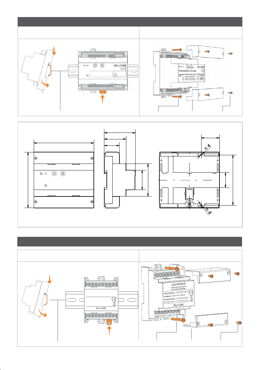
73,0
140,7
51,0
35,5
130,0
Frontal view
Lateral view
The accumulator will be connected to the hubs of the power supply, after the commissioning of the system.
A3,5 x 32 screw (2 pcs.) B2,9 x 9,5 screw (4 pcs.)Protection lid (2 pcs.)
46,0
76,0
Back view
42,8
35,5
117,5
4.4 Installation of the audio connection box
DIN rail mounting
Wall mounting
1
ACB.4DN.BLW
Audio Verbindungsbox für
Audio Türsprechanlagen
Haupteingang: 1 Audio BUS Signal
Ausgang: 4 Audio BUS Signale
Hauptausgang: 1 Audio BUS Signal
Betriebsspannung: 12-14 V Gleichspannung
2
3
RetainerD IN rail
A3,5 x 32 screw (2 pcs.) B2,9 x 9,5 screw (4 pcs.)Protection lid (2 pcs.)
Frontal view
Lateral view Back view
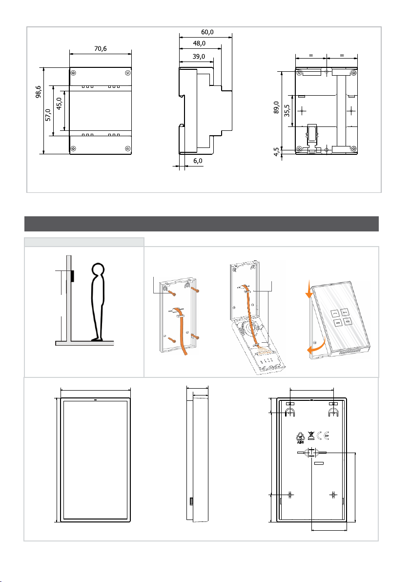
4.5 Installation of the audio terminal
Before starting...
155 cm
The terminal will be placed at 155 cm
height (recommended height)
96,5
171,5
Frontal view Lateral view
A3,5 × 35(32) screw
(4 pcs.)
18 cm
Cable length
(from the wall)
29,5
21
Cable retainers
– adapters
1
2
20,5
113,5
37,5
Back view
60,0
95,7
48,2
4.6 Installation of the outdoor panel
The outdoor panel is installed at the entrance of the property or building, on the body closest
to the access door, at a height of approx. 1.7 m (upper part) from the ground, protected from
rain and sunrays. The outdoor panel keys numbering is from the bottom up, the first key
meaning address 1.
Before starting...
Torx
screw
1
170 cm
-
5 c
-5 c
The frame of the
m
m
case must be at
the level of the
wall's surface.
2
The outdoor panel is installed at the
entrance to the building, on the body
closest to the entrance door.
Frontal view
20cm
Cable length
Cable length
Lateral view
Name display of inhabitant
3
Torx screw
Back view
Remove the plastic pad from
the keyboard module
Remove the plastic pad from the keyboard module
Insert the pad back in the
keyboard module

CON N E CTIO N DIAG RAM
5
Doorbell
1st FAMILY
Dbl
CD
+14V
GND
2nd FAMILY
Terminal 1
BLUE
BROWN
GREEN
ORANGE
(AWG 24)
UTP CAT 5e
BLUE
ORANGE
OUT
3
GND
GND
OUT
IN
3
CD
+14V
1
1
CD
+14V
CD
OUT
OUT
+14V
CD
IN
IN
+14V
IN
GREEN
GND
GND
Dbl
BROWN
3
1
ORANGE
+14V
+14V
+14V
ORANGE
4
2
Doorbell
CD
GND
Terminal 2
BLUE
GREEN
BROWN
(AWG 24)
UTP CAT 5e
GREEN
BLUE
BROWN
APTAPT
4
4
CD
GND
2
2
CD
GND
AC B.4DN.xxy
Audio connection box
BLUE
BROWN
ORANGE
ACC
12V/7 Ah
Accumulator
2 x 0,5 mm²
ORANGE
cable
GREEN
(AWG 24)
UTP CAT 5e
BLUE
GREEN
BROWN
(Optional)
Door Opening button
or
Drive current
Alternative current
electromagnetic lock
AUX command
electromagnetic lock
LC
+ACC
-ACC
N
F
Elect rical panel
2x Sig. 10A
230 V c.a/50Hz
+14V
+14V
cable
ORANGE
3 x 0,75 mm²
ORANGE
+14 V
CD OUT
CD IN
BLUE
BLUE
CD
GND
GNDPVin 1
GREEN
UTP CAT 5e
GREEN
GND
(AWG 24)
BROWN
BROWN
Vout
P
Panel
APE.3S0.xxy
+Uv
BUT
GNV
OUT
GNV 1
GNV 2
Vin 2
APE.3F0.xxy
LA/C
Ucam
LA
GND
AUX 2
AUX 1
Supply control unit
INDOO R
OUTDO OR

G
ND
L
A
AU
X 2
A
U
X
1
5.1 Installation of the electromagnetic lock (optional)
Drive current (DC )
2 x 0.75 mm²
BUT
LC
LA/C
LA
supply control unit
cable
LC1
LC2
Drive current
electromagnetic lock (DC)
The supply control unit can supply a current of
max. 1A for the supply of the lock.
The tension of +14 V d.c. is present on the LC
hub of the supply control unit.
The connection of a lock actuating button
from the interior of the building will be made
at the BUT and LC hubs of the supply
control unit.
Alternative current (AC)
Transformer
BUT
LC
LA/C
LA
supply control unit
5.2 Auxiliary command connection (optional)
12 Va.c.230 Va.c.
2 x 0.75 mm²
cable
Alternative current
electromagnetic lock (AC)
Relay contact
Maximum switched current: 1.5 A
COMMISIO NING OF THE SYSTEM
6
6.1 Description of the supply control unit
The supply control unit includes:
*PROG. : programming button
LE D signaling of programming /
Front lid defect within the system
PROG
STROMVERS ORGUNGSEINH EIT (SCU.VDN.BLW)
SCHLOSSÖFFNUNGSZEIT
(sekunden)
TI ME:
Lock timing adjustment
* The KIT does not require programming. This button is used only if you add additional
terminals or panels to the system.
S2
VideoS1Audio
EINGANG: 230V Wechselspannung 50Hz, 0.4A
1
2
10
AUSGANG 1: 14V, 2A Gleichspannung (S1)
3
9
AUSGANG 2: 14V, 0.5A Gleichspannung (S2)
4
8
7
5
6
AUX Command
(automation)
S1: presence of tension at the +14V - GN D hubs
S2: existence of tension at the +Uv - GNV hubs
Protection lid for connections
ACHTUNG! Lebensgefahr,
gerät nicht öffnen!
GEFAHR EINES
STROMSCHLAGS!
Front lid
Protection lid for connections
6.2 Checking the precision of the connections in the system and
the connection of the supply control unit
Check the precision of the connections in the system!
The +14V , GND , CD signals are common to all components of the system.
Any short circuit between them leads to the non-operation of the entire system.
With an ohmmeter, check that there is no short circuit between any hubs, anywhere in the system.
Connect the supply control unit (SCU) to the 230 V a.c. network, by connecting the two automatic 10A fuses,
installed on phase and null.
Optionally, connect the accumulator to the +ACC and –ACC hubs of the S CU.
PAY AT TE NT IO N to the polarity of the accumulator!
Check the existence of the supply tensions with the values mentioned below, at the hubs of the SCU (use a
drive current voltmeter).
Tensions measured at the hubs of the SCU : +14V – G ND /13,8 … 14,3Vc.c.
The tension +Uv – GND /13,5 … 14,3Vc.c. is not used by the audio systems.
Tensions measured at the hubs of the outdoor panel and at the hubs of the terminals + 14V - GND
min. 12 Vd.c.
6.3 Checking the functions and adjustments
Check anywhere in the installation, during the call and the communication, and make sure that the +14V
– GND supply tension is higher than 12,0V.
Check the functions of the terminals and of the outdoor panel: call, communication, access, audio
monitoring. The system is adjusted by the producer in what concerns the audio part, for standard
functioning conditions
How to adjust the volume of the audio terminal
Through consecutive touches of the VOL UM E key, different audition levels are obtained: OFF (mute) –
red LED, MEDIUM white-red LE D, MAXIMUM – white LED
After checking, leave the terminal on the open volume position (white LED on).
6.4 Troubleshooting
Any intervention in the system will be made with the system disconnected from
the 230Va.c. supply network (the phase and null fuses are opened) and from the
accumulator (the +ACC hub is disconnected).
No.
0
Problem Signaling
The system functions
correctly
Control unit:
S1: green
S2: green
PROG:
Possible causes
Solutions

The system does not
function (supply
1
control unit without
accumulator)
Control unit:
S1:
S2:
PROG:
Lack of tension from
the 230Va.c. network
Check the 10A fuses from
the electrical panel and
the 1,6A Fuse 1 from the
supply control unit input.
Check the continuity of
the supply cables.
The system does not
function (supply
2
control unit without
accumulator)
The CALL does
3
not function
The CALL does
4
not function
Control unit:
S1: intermittent green
S2:
PROG:
Control unit:
S1: green
S2: green
PROG:
Terminal:
The keyboard is
functioning, it does
not take the call
command.
Outdoor panel:
Emits an error signal .
Control unit:
S1: green
S2: green
PROG: intermittent red
Terminal:
The keyboard is
functioning, it does
not take the call
command.
Outdoor panel:
Emits an error signal.
Short circuit in the
system between +14V
and GND
No CD connection
at the hubs of the
terminal, or CD
wire interrupted
before reaching the
hubs of the terminal
Short circuit between
the CD and GND
or +14V connections
Identify the spot of the
short circuit. Remedy the
defect and turn the
system on.
Connect the CD to the
terminal or check the
continuity of the CD
wire from the audio
connection box to
the terminal.
Remedy the short circuit.
(by case)
The system functions
(supply control unit
5
with accumulator)
The system functions
(supply control unit
6
with accumulator)
Control unit:
S1: red –
intermittent green
S2: green
PROG:
Control unit:
S1: red –intermittent
green
S2: green
acoustic signal
PROG:
The accumulator is in
charging mode
Defect accumulator or
discharged
ok
Defect accumulator
or discharged
The system functions
(supply control unit
7
with accumulator)
USE
7
Control unit:
S1: red
S2:
PROG:
7.1 User safety instructions
Do not hit the glass screen with hard objects!
If the front glass screen cracks, D O NOT touch the product!
7.2 Use of the audio terminals
1 STAND-BY
At the first touch, the keyboard is backlit and the terminal may receive the
following commands:
AU DIO MONITO RING
Monitoring duration: 10 sec.
By touching this key, you may listen to what goes on at the entrance, in front of the
outdoor panel. Monitoring is not possible if another terminal of the system is
being called or is during communication.
Lack of tension from the
230Va.c. network
The system functions
powered by the
accumulator.
Check the 10A fuses from
the electrical panel and
the 1,6A Fuse 1 from the
supply control unit input.
Check the continuity of
the supply cables.
Stand-by
Call
VOLU ME ADJUSTMENT OR
“TERMINAL TURNED OFF”
By successive touches of this key, the 3 volume levels are passed through:
maximum (white LED), medium (red-white L ED) and turned off (red LED). The
red LED will remain permanently turned on until the key is pressed again.
2 CALL AND COMMUNICATIO N
Call duration: maximum 1 min.
ANSWER THE CALL
Communication duration: maximum 2 min.
The LED of the key blinks.
By touching the key, communication is initiated. The LE D does not blink
anymore.
Do not touch the key during communication.
END CO MMUNICATIO N
WITHOUT ACC ESS!
The second touch of the key ends communication without granting access and
the terminal returns to stand-by mode.
 Loading...