

Page 1

dashboard 300
20-FUNCTION CYCLE COMPUTER
Page 2

table of contents
COMPONENTs ..................................................................................................................... 3
INsTaLLaTION .....................................................................................................................4
PROgRaMMINg ThE COMPUTER ........................................................................................5
addITIONaL FUNCTION MOdEs ..........................................................................................7
TROUbLEshOOTINg ..........................................................................................................12
COMPOsaNTs ................................................................................................................... 13
INsTaLLaTION ...................................................................................................................14
PROgRaMMaTION dE L’ORdINaTEUR ...............................................................................15
FONCTIONs sUPPLÉMENTaIREs .......................................................................................17
dÉPaNNagE ......................................................................................................................22
COMPONENTEs ................................................................................................................. 23
INsTaLaCIÓN ....................................................................................................................24
CÓMO PROgRaMaR EL CICLOCOMPUTadOR ....................................................................25
MOdaLIdadEs dE FUNCIÓN adICIONaLEs .......................................................................27
LOCaLIZaCIÓN dE aVERÍas...............................................................................................32
Page 3
components
WARNING!
· Improper installation of this or any other bike
computer can result in an accident. Read
instructions carefully.
· Call 1-800-456-BELL if you have any questions.
· Check mounting hardware & transmitter installation
before each ride for adjustment and secure t.
· This computer will not t all bikes. If you cannot get a
secure installation per the instruction manual, do not
use this computer.
3
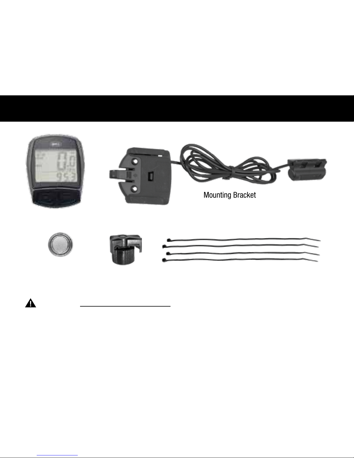
Computer Battery
(3.0V/CR2032)
Cable Ties (4)
Magnet
Computer Unit
Mounting Bracket
Page 4
installation
4
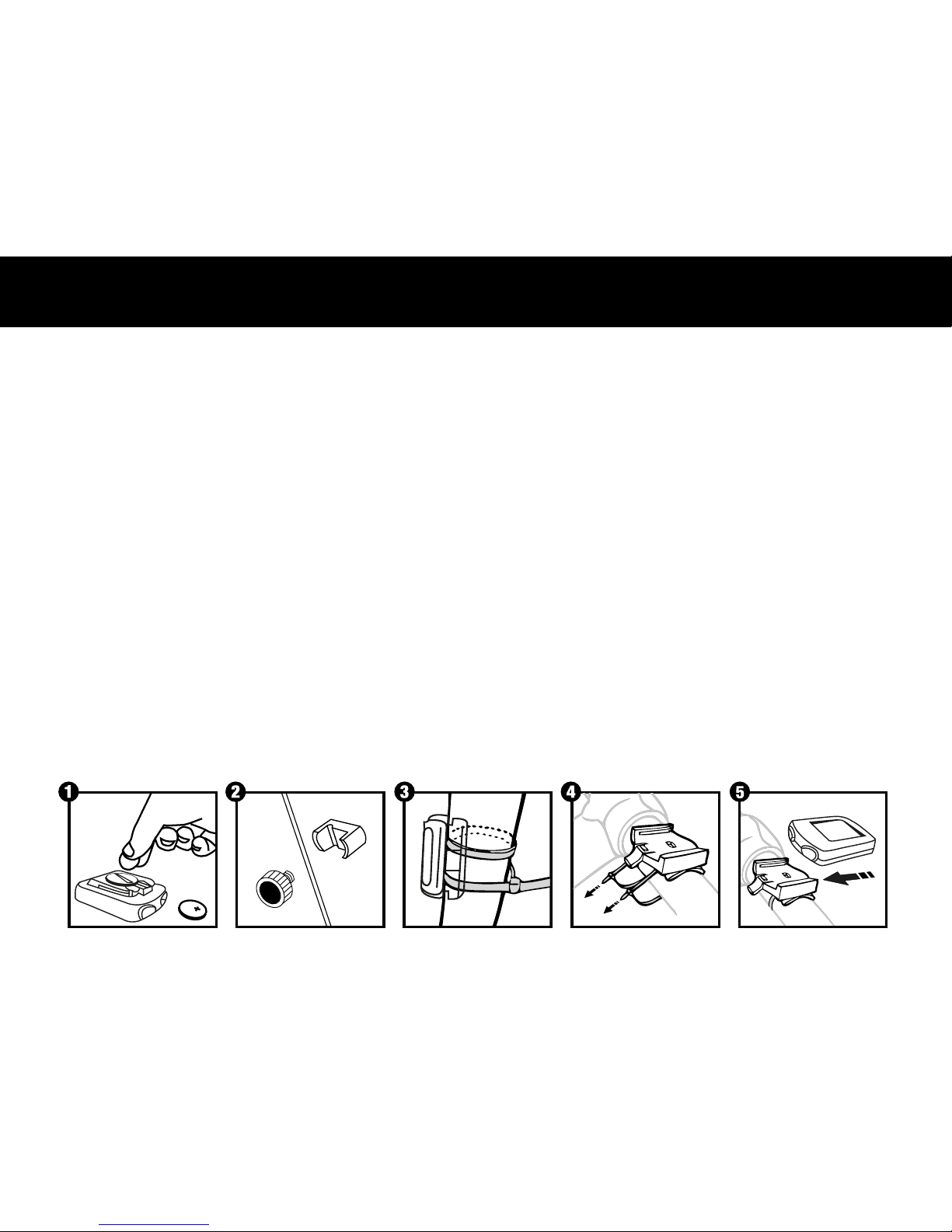
STEP 1: Install the Battery– Remove the battery cover from the bottom of the computer using a small coin
(Figure 1). Install the computer battery (3.0V/CR2032) with the positive (+) pole facing up. Replace the battery
cover and tighten. Note: Replacing the battery will erase all stored information. When installing a new battery
after having used the computer, make sure to write down the odometer value before changing the battery so
you can later re-enter it in the computer.
STEP 2: Install the Magnet to the Wheel – Clamp the magnet to a spoke on the right side of the front
wheel (Figure 2). Make sure that the magnet is facing the outside of the wheel so that the at side of the
magnet passes in front of the sensor.
STEP 3: Attach the Sensor to the Fork – Attach the computer sensor to the right fork leg using two of the
cable ties provided. Make sure the metal side of the sensor is facing the wheel. Do not fully secure the cable
ties yet, as the sensor location may require further adjustment (Figure 3). Adjust the sensor and magnet location so that clearance between the two is no greater than 2mm. (Figure 4). The magnet should now pass by
the tip of the sensor when the wheel rotates.
STEP 4: Install the Mounting Bracket & Computer – Attach the mounting bracket to the handlebar by
using the remaining 2 cable ties as shown in (Figure 4). Make sure the mounting bracket is clamped tightly
and will not slip on the handlebar. Insert the computer into the mounting bracket (Figure 5). When adjustments
have been made and the computer operates correctly, tighten completely all nuts and bolts.
Sensor
or
Magnet
5mm
Sensor
Magnet
Sensor
Bicycle fork
Page 5

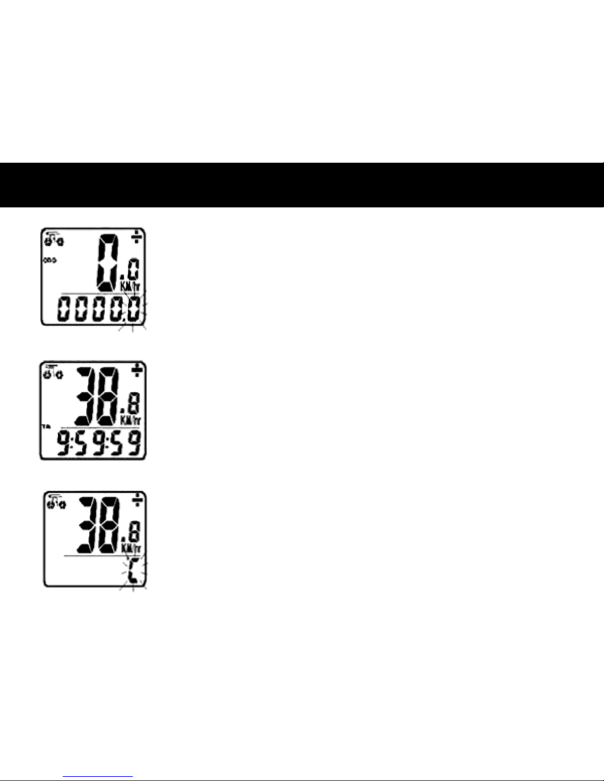
STEP 1: Set the Wheel Value– First, using
the table provided, determine the correct, 4-digit,
wheel value based on the size of your tire. The
wheel value is the distance in millimeters per one
revolution of the wheel. Next, press and hold the
left and right button for two seconds. The preset
value “2124” should appear with the digit “4”
ashing. Press the right button to modify the digit
to the correct setting. Once correct digit is shown,
press the left button to move to the next digit.
Repeat until all four digits are set to the correct
wheel value for your bike.
STEP 2: Set KM or Mile Selection– After setting the wheel value, the KM/M selection will appear. Press the
RIGHT button to choose kilometer or mile selection. Press the LEFT button to conrm.
STEP 3: Set Age and Weight– After setting the KM/M selection, two numbers will appear. Enter your age
as the large number above the horizontal line. Press the RIGHT button to modify the “ones” digit to the correct
setting. Press the LEFT button to conrm. Repeat for the “tens” digit. Enter your weight as the smaller number
below the horizontal line following the same steps. By entering your actual age and weight, you will get a more
accurate calculation of calories and fat burned
NOTE: The computer will default to kilograms (80kg) or pounds
(160lb) based on your selection of kilometers or miles respectively.
5
Road Bike
20" 1596
22" 1759
24" 1916
26" 2073
27"/700c 2124
28" 2237
Mountain Bike
24" 1888
26" 2045
26x2.25" 2077
27" 2155
29x2.1" 2288
29x2.23 2326
programming the computer
Page 6
programming the computer
6
STEP 4: Set Distance for Maintenance Reminder– After setting age and weight, the preset number of 600
km (or miles) will ash. Press the RIGHT button to select 200, 400, 600 or 800 km (or mile) maintenance interval,
then press the LEFT button to conrm. When your odometer (ODO) reaches the selected distance interval, the
wrench icon ( ) will ash, reminding you to service your bicycle (check tires and other parts for wear, lubricate
chain, etc…). Press the LEFT button to stop the wrench icon ( ) from ashing.
STEP 5: Set the Clock– The clock function will appear at the bottom of the screen. Press and hold the LEFT
button for 3 seconds to get a ashing "24H" symbol. Press the RIGHT button to select between 12 and 24 hour
format. Press the LEFT button to conrm. Next, the hour digits will start to ash. Use the RIGHT button to select the
hour and press the LEFT button to conrm. Repeat for minutes digits. Press the LEFT button once more to set the
clock. Press the RIGHT button to enter ODO mode.
STEP 6: Test to Ensure Proper Installation– Now that the computer is programmed, insert it into the
bracket. Spin the front wheel. The speed tendency icon in the upper left corner of the screen should be turning as
the computer starts recording data (Refer to Troubleshooting in case of problems).
Page 7
additional function modes
7
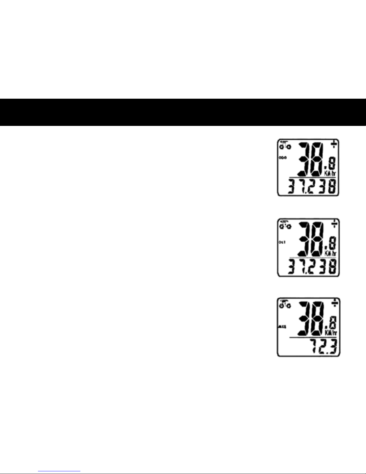
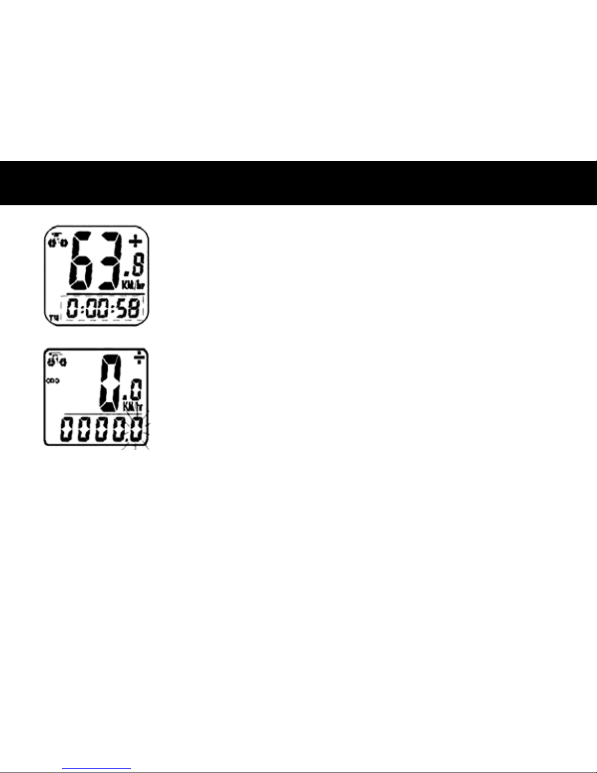
ODOMETER (ODO)– Total distance traveled is indicated by “ODO” and displayed
on the bottom line. To reset ODO, press both RIGHT and LEFT buttons for 3 seconds
or remove and replace the battery. Now press the RIGHT button to advance to the
DST mode.
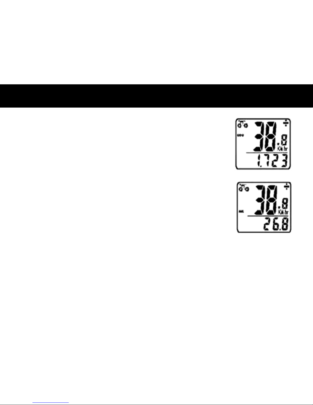
TRIP METER (DST)– Trip distance is indicated by DST and is displayed on the
bottom line. The Trip Meter is activated automatically with speedometer input (comes
on automatically when you begin riding, turns off when you stop). To reset DST to zero,
press and hold the RIGHT and LEFT buttons for 3 seconds. Note that TM (Trip Time)
& AVS (Average Speed) will also be reset at that time. Now press the RIGHT button to
advance to the MXS mode.
MAXIMUM SPEED (MXS)– Maximum speed is indicated by MXS and is displayed
on the bottom line. Maximum speed is stored in memory and updates only when a
higher speed is reached. To reset MXS, press and hold the LEFT button for 3 seconds.
Now press RIGHT button to advance to Average Speed (AVS) mode.
Page 8
additional function modes
8
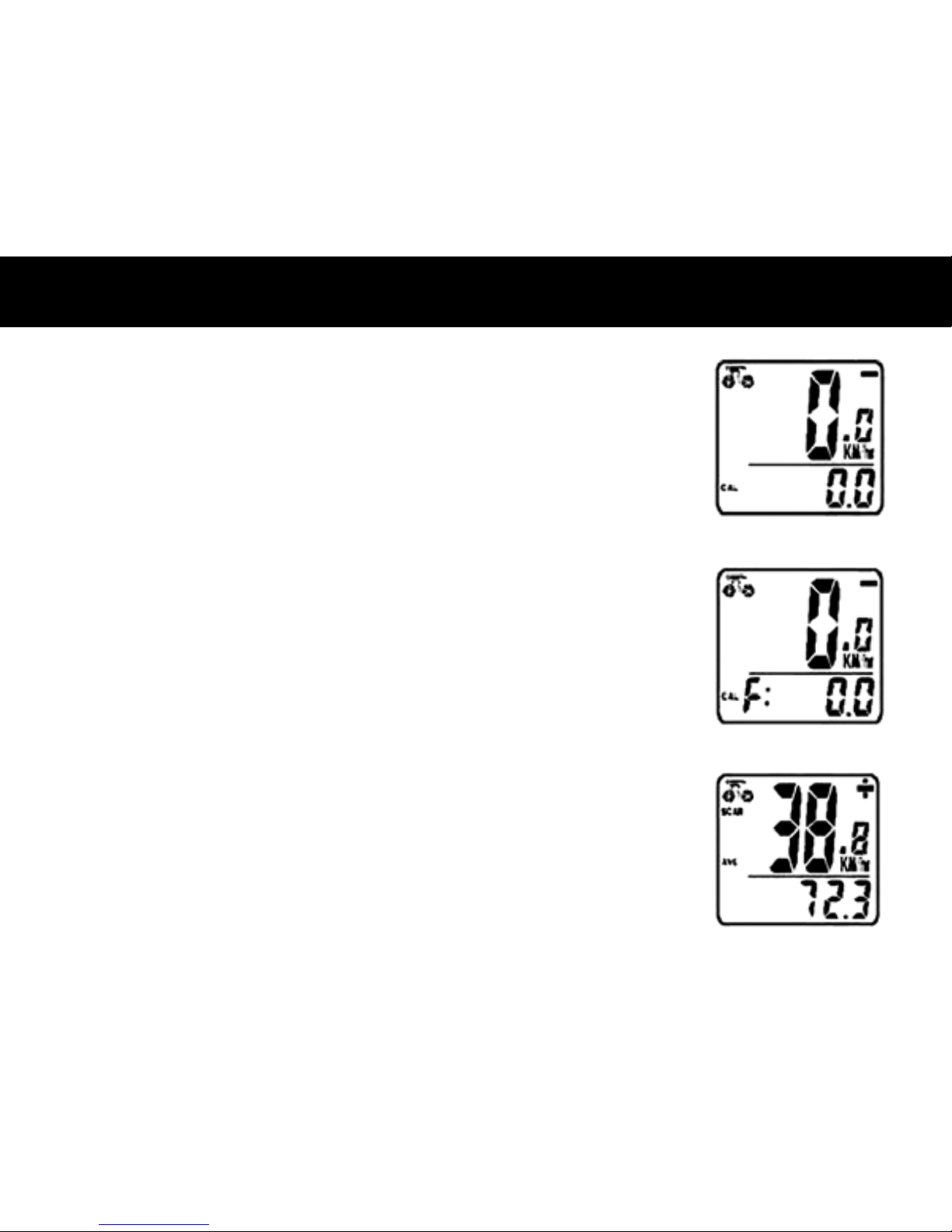
AVERAGE SPEED (AVS)– Average speed is indicated by AVS and is displayed on
the bottom line. AVS works in conjunction with the Trip Timer (TM) to calculate the
average speed for a specic trip. Now press the RIGHT button to advance to the Trip
Timer (TM) mode.
TRIP TIMER (TM)– Trip Timer is indicated by TM and is displayed on the bottom
line. The Trip Timer is activated automatically with computer input (comes on
automatically when you begin riding, turns off when you stop). It records only the time
actually spent riding. To reset TM to zero, return to DST (Trip Meter) mode and reset
to zero per the instructions above. Return to TM mode and press RIGHT button to
advance to TEMPERATURE (TEMP) mode.
TEMPERATURE (TEMP)– Your computer has a thermometer to measure outdoor
temperature. To select between Celsius (C) and Fahrenheit (F) readout, press and
hold the LEFT button for 3 seconds until you see a ashing "F". Press LEFT button
to conrm Fahrenheit (F) readout. If you prefer Celsius readout, press RIGHT button
to switch to Celsius (C) and then press LEFT button to conrm. Now press the RIGHT
button to advance to Calorie (CAL) mode
Page 9
additional function modes
CALORIES BURNED (CAL)– This function estimates the number of calories burned
while riding, based on the age and weight inputed by the user. To reset CAL, press
and hold the LEFT button for 2 seconds. Now press the RIGHT button to advance to Fat
Burned (FAT) mode.
FAT BURNED (FAT)– This function estimates the number of fat grams burned while
riding, based on the age and weight inputed by the user. To reset FAT, press and
hold the LEFT button for 2 seconds. Now press RIGHT button to advance to the SCAN
(SCAN) mode.
SCAN – The Scan mode conveniently rotates DST, MXS, AVS, and TM readings on the
computer screen without the need to press any buttons. Now press the RIGHT button
to return to the Clock mode.
9
Page 10
additional function modes
10
FREEZE FRAME MEMORY– Press the LEFT button, Freeze Frame Memory can lock
the display at the end of a ride segment and information TM, DST and AVS which will
be ashing, can be read at a later time by the RIGHT key. To release the memory, press
the LEFT key until the display digit is static again. This is particularly useful when
crossing the nish line of a time trial, since the TM cannot be stopped manually.
ODOMETER SAVE FUNCTION– The SAVE function allows you to keep the impor-
tant data of total distance (ODO) even after battery replacement. To set ODO, after
battery replacement and wheel size setting, press RIGHT button to ODO mode and
then hold LEFT button for 2 seconds until the last digit ickering. To adjust number,
press the RIGHT button and then press the LEFT button to conrm and select digit to
be input. Repeat this sequence to reach the desired odometer value. Press the LEFT
button again to return to normal ODO mode.
AUTO STOP/START– To preserve batteries, the cycle computer will automatically
switch off if the unit is left unused for over 5 to 6 minutes. Display will reappear with a
press on either button or input from the sensor.
Page 11
SPEEDOMETER– Instantaneous Speed is indicated on the top line. The range of
measurement is from 0 to 99 KM/hr (0 to 99 M/hr) and accuracy is ±0.5 KM/hr (M/hr).
SPEEDOMETER COMPARATOR– A "+" or "-" sign appears to the right of the
speed. "+" indicates you are traveling faster than your average speed (AVS). A "-"
indicates you are riding slower than your average speed.
SPEED TENDENCY– A cyclist symbol appears to the left of the speed. The wheel turns
forward to indicate acceleration. The wheel turns backward to indicate deceleration.
ELECTROLUMINESCENT BACKLIGHT– The backlight illuminates the computer screen for easier viewing in
dark or low light settings. It can be turned on in two ways:
1) Hold the RIGHT button for 2 seconds. The electroluminescent backlight will illuminate for 8 seconds and then
the computer will go into Scan mode.
2) Press the LEFT button. The electroluminescent backlight will illuminate for 4 seconds.
11
additional function modes
Page 12

troubleshooting
12
PROBLEM
No speedometer
display and/or no
data reading
Slow display
response
Display shows
irregular features
Black display
POSSIBLE CAUSE
Possible interference from electrical sources
Improper magnet/sensor alignment
Poor battery contact or low/dead battery
Temperature outside of operational
limits (0-60°C or 32-140°F)
Poor battery contact or low/dead battery
Temperature too hot or display exposed
to sunlight too long
Computer damaged or dropped
RECOMMENDED ACTION
Move computer to different area
Ensure speedometer sensor and magnet
are properly installed and aligned (p.3)
Replace Battery
Only use computer when temperature is
within operational limits
Replace battery
Only use computer when temperature is
within operational limits. Remove from
sunlight
Computer is broken
No trip distance
reading
Improper sensor/magnet alignment Ensure proper alignment
Page 13

AVERTISSEMENT!
· L’installation incorrecte de tout ordinateur pour
bicyclette, notamment celui-ci, peut entraîner
un accident. Prière de lire les instructions
attentivement.
· Composer le 1-800-456-BELL pour poser toute
question concernant l’installation.
· Vérier les pièces nécessaires au montage et à
l’installation de l’émetteur avant chaque départ
pour s’assurer que le réglage est bon et l’adaptation
sécurisée.
· Cet ordinateur ne s’adapte pas sur toutes les bicyclettes. Si vous ne pouvez pas sécuriser l’installation
en suivant les instructions du manuel, n’utilisez pas
cet ordinateur.use this computer.
Attaches de câble (4)
Aimant
Ordinateur
Patte de support
composants
13
Pile pour ordinateur
(3.0V/CR2032)
Page 14

installation
14
ÉTAPE 1 : Installation de la pile – Enlever le couvercle du compartiment de la pile au bas de l'ordinateur à l’aide
d’une petite pièce de monnaie (Figure 1). Installer la pile de l’ordinateur (3.0V/CR2032), le pôle positif (+) faisant
face vers le haut. Remettre le couvercle du compartiment en place et le revisser. Remarque : Le remplacement de
la pile efface toute information enregistrée. Prendre soin d’inscrire le chiffre du compteur kilométrique avant de remplacer la pile usée par une pile neuve, an de pouvoir saisir à nouveau ce chiffre, plus tard, dans l’ordinateur.
ÉTAPE 2 : Installation de l’aimant sur la roue – Fixer l’aimant sur un rayon, côté droit de la roue avant (Figure
2). Vérier que l’aimant fait face vers l’extérieur de la roue de manière à ce que le côté plat de l’aimant passe devant
le capteur.
ÉTAPE 3 : Fixation du capteur sur la fourche – Fixer le capteur du compteur kilométrique sur le montant droit
de la fourche, à l'aide de deux des attaches de câble fournies. Vérier que le côté métallique du capteur soit face
à la roue. Ne pas serrer dénitivement les attaches de câble à ce stade, car il pourra peut-être s’avérer nécessaire
d’ajuster l’emplacement du capteur (Figure 3). Ajuster l’emplacement du capteur et de l’aimant pour que l’écart
entre les deux ne soit pas plus grand que 2 mm (Figure 4). L’aimant doit alors passer devant l’extrémité du capteur
lorsque la roue tourne.
ÉTAPE 4 : Installation du support et de l’ordinateur – Fixer le support sur le guidon à l'aide des deux
attaches de câble restantes comme indiqué (Figure 4). Vérier que le support est solidement attaché et qu’il ne
pourra pas glisser sur le guidon. Insérer l’ordinateur dans le support (Figure 5). Quand les réglages sont terminés et
que l'ordinateur fonctionne correctement, serrer à fond tous les écrous et toutes les vis.
Sensor
or
Magnet
5mm
Sensor
Magnet
Sensor
Bicycle fork
Page 15

ÉTAPE 1 : Congurer la valeur de référence
de la roue –
À l’aide du tableau ci-inclus, déterminer la valeur de référence correcte, à quatre
chiffres, caractérisant la roue, basée sur la dimension du pneu. La valeur de référence de la roue est
la distance en pouces parcourue par une révolution
de la roue (longueur de la circonférence). Ensuite,
appuyer sur les boutons de GAUCHE et de DROITE
et les maintenir enfoncés pendant deux secondes.
La valeur de consigne « 2124 » doit apparaître
avec le quatrième chiffre clignotant. Appuyer sur le
bouton de DROITE pour modier le chiffre, jusqu’à
ce qu’il atteigne sa valeur correcte. Une fois que
le chiffre correct apparaît, appuyer sur le bouton de GAUCHE pour passer au chiffre suivant. Recommencer
l’opération jusqu’à ce que les quatre chiffres aient la valeur de la longueur de circonférence correcte de la roue
de votre bicyclette.
ÉTAPE 2 : Choix entre km ou mille – Après avoir conguré la valeur de référence de la roue, la sélection
KM/M (km/mille) apparaît. Appuyer sur le bouton de DROITE pour choisir les kilomètres ou les milles. Appuyer
sur le bouton de GAUCHE pour conrmer.
ÉTAPE 3 : Saisie de l’âge et du poids – Après avoir conguré le choix de l’unité km/mille, deux nombres
apparaissent. Le grand nombre au-dessus de la ligne horizontale indique l’âge. Appuyer sur le bouton de DROITE
pour modier le chiffre des unités à la valeur correcte. Appuyer sur le bouton de GAUCHE pour conrmer. Recommencer pour le chiffre des dizaines. Saisir le poids dans le champ du nombre plus petit, sous la ligne horizontale,
BICYCLETTE DE
RANDONNÉE
20" 1596
22" 1759
24" 1916
26" 2073
27"/700c 2124
28" 2237
BICYCLETTE DE
MONTAGNE
24" 1888
26" 2045
26x2.25" 2077
27" 2155
29x2.1" 2288
29x2.23 2326
15
programmation de l’ordinateur
Page 16

programmation de l’ordinateur
16
en suivant les mêmes étapes que ci-dessus. La saisie de l'âge et du poids exacts et de l'âge et du poids exacts exacts
permet d’obtenir un calcul plus précis des calories et de la graisse « brûlées ».
REMARQUE : L’ordinateur choisira
l’unité de poids par défaut en fonction de l’unité de distance choisie : kilogrammes (par exemple 80 kg) si le choix est en
kilomètres, livres (par exemple 160 livres) si le choix est en milles.
ÉTAPE 4 : Conguration de la distance comme rappel pour l’entretien – Après la conguration de
l’âge et du poids, le nombre préconguré de 600 km (ou milles) apparaît en clignotant. Appuyer sur le bouton de
DROITE pour choisir l’intervalle des interventions d’entretien, soit 200, 400, 600 ou 800 km (ou milles), puis
appuyer sur le bouton de GAUCHE pour le conrmer. Quand le compteur kilométrique (ODO) atteint la distance
correspondant à l’intervalle choisi, une icône de clé anglaise ( ) apparaît en clignotant pour vous rappeler
d’effectuer l’entretien de votre bicyclette (vérier les pneus et autres pièces pour l’usure, le graissage de la chaîne,
etc.). Appuyer sur le bouton de GAUCHE pour arrêter le clignotement de l’icône de clé anglaise ( ).
ÉTAPE 5 : Mise à l’heure – La fonction Horloge apparaît en bas de l’écran. Appuyer sur le bouton de GAUCHE
pendant trois secondes pour afcher le message clignotant « 24H ». Appuyer sur le bouton de DROITE pour
choisir entre les formats « 12H » et « 24H ». Conrmer en appuyant sur le bouton de GAUCHE. Ensuite, l’afchage
des heures commence à clignoter. Utiliser le bouton de DROITE pour choisir l’heure et appuyer sur le bouton de
GAUCHE pour conrmer. Recommencer pour les minutes. Appuyer sur le bouton de GAUCHE encore une fois pour
mettre l’horloge à l’heure. Appuyer sur le bouton de DROITE pour passer au mode Compteur kilométrique (ODO).
ÉTAPE 6 : Test d’installation correcte – L’ordinateur étant désormais programmé, l’insérer dans son
support. Faire tourner la roue avant. L'icône du comparateur de vitesses dans le coin gauche, en haut de l’écran,
devrait commencer à tourner pendant que l’ordinateur commence à enregistrer les données (consulter la section
Dépannage si un problème survient).
Page 17

COMPTEUR KILOMÉTRIQUE (ODO) – La distance totale parcourue est indiquée
par « ODO » et est afchée sur la ligne du bas. Pour remettre le compteur ODO à zéro,
appuyer sur les deux boutons de DROITE et de GAUCHE pendant trois secondes ou
enlever et remplacer la pile. Appuyer ensuite sur le bouton de DROITE pour passer
au mode Totalisateur partiel (DST).
TOTALISATEUR PARTIEL (DST) – La distance parcourue pendant une course
ou randonnée est indiquée par DST et est afchée sur la ligne du bas. Le totalisateur
partiel est activé automatiquement par l'entrée d’information dans le compteur
kilométrique (activation automatique quand on commence à rouler et désactivation
quand on s’arrête de rouler). Pour remettre le totalisateur (DST) à zéro, appuyer sur les
boutons de DROITE et de GAUCHE pendant trois secondes. Il faut noter que les valeurs
de la durée de la course (Trip Timer, TM) et de la vitesse moyenne (Average Speed,
AVS) sont également remises à zéro à ce stade là. Appuyer ensuite sur le bouton de
DROITE pour passer au mode Vitesse maximum (MXS).
VITESSE MAXIMUM (MXS) – La vitesse maximum est indiquée par le sigle MXS
et est afchée sur la ligne du bas. La vitesse maximum est enregistrée dans la
mémoire et ne s’actualise que si l'on atteint une vitesse supérieure. Pour remettre la
valeur MXS à zéro, appuyer sur le bouton de GAUCHE et le maintenir enfoncé pendant
trois secondes. Appuyer ensuite sur le bouton de DROITE pour passer au mode
Vitesse moyenne (AVS).
fonctions supplÉmentaires
17
Page 18

fonctions supplÉmentaires
18
VITESSE MOYENNE (AVS) – La vitesse moyenne est indiquée par le sigle AVS
et est afchée sur la ligne du bas. La vitesse moyenne fonctionne de pair avec le
Chronométrage (TM) pour le calcul de la vitesse moyenne d’une course particulière.
Appuyer sur le bouton de DROITE pour passer au mode Chronométrage (TM).
CHRONOMÉTRAGE (TM) – Le chronométrage de la course est indiqué par TM et
est afché sur la ligne du bas. Le chronométrage est activé automatiquement par
l'entrée d’information dans le compteur kilométrique (activation automatique quand
on commence à rouler et désactivation quand on s’arrête de rouler). Le chronomètre
n’enregistre que la durée effective du pédalage. Pour remettre le chronomètre TM à
zéro, repasser en mode Totalisateur partiel (DST) et remettre à zéro selon les instructions ci-dessus. Repasser en mode TM et appuyer sur le bouton de DROITE pour
passer au mode Température (TEMP).
TEMPÉRATURE (TEMP)–
L'ordinateur comprend un thermomètre pour mesurer la
température extérieure. Pour choisir la lecture en degrés Celsius (°C) ou Fahrenheit (°F),
appuyer sur le bouton de GAUCHE pendant trois secondes jusqu’à ce que la lettre « F »
apparaisse en clignotant. Appuyer sur le bouton GAUCHE pour conrmer la lecture en
degrés Fahrenheit (F). Si l’on préfère lire en degrés Celsius, appuyer sur le bouton de
DROITE pour passer aux degrés Celsius (C) et appuyer sur le bouton de GAUCHE pour
conrmer. Appuyer ensuite sur le bouton de DROITE pour passer au mode Calories (CAL).
Page 19

CALORIES BRÛLÉES (CAL) – Cette fonction estime le nombre de calories brûlées
pendant le pédalage, en fonction de l’âge et du poids congurés par l’utilisateur.
Pour remettre le mode CAL à zéro, appuyer sur le bouton de GAUCHE et le maintenir
enfoncé pendant deux secondes. Appuyer ensuite sur le bouton de DROITE pour
passer au mode Graisse brûlée (FAT).
GRAISSE BRÛLÉE (FAT) – Cette fonction estime le nombre de grammes de
graisse brûlés pendant le pédalage, en fonction de l’âge et du poids congurés par
l’utilisateur. Pour remettre le mode FAT à zéro, appuyer sur le bouton de GAUCHE et le
maintenir enfoncé pendant deux secondes. Appuyer ensuite sur le bouton de DROITE
pour passer au mode Balayage (SCAN).
BALAYAGE (SCAN) – Le mode Balayage fait passer commodément de l’un à l’autre
des écrans DST, MXS, AVS ou TM de l’ordinateur sans besoin d’appuyer sur aucun
bouton. Appuyer ensuite sur le bouton de DROITE pour passer au mode Horloge.
fonctions supplÉmentaires
19
Page 20

fonctions supplÉmentaires
20
MÉMOIRE DES DONNÉES INSTANTANÉES – Appuyer sur le bouton de GAUCHE,
la mémoire des données instantanées peut verrouiller l’afchage à la n d’un segment
de course et les informations TM, DST et AVS clignotent et peuvent être lues plus tard
en appuyant sur la touche de DROITE. Pour libérer la mémoire, appuyer sur la touche
de GAUCHE jusqu’à ce que l’afchage des chiffres redevienne statique. Ceci est
particulièrement utile lorsqu’on franchit la ligne d’arrivée d’une course chronométrée
parce que la fonction chronométrage TM ne peut pas être arrêtée manuellement.
FONCTION D’ENREGISTREMENT DU COMPTEUR KILOMÉTRIQUE – La fonc-
tion ENREGISTREMENT (SAVE) permet de conserver les données importantes telles
que la distance totale (ODO) même après le remplacement de la pile. Pour congurer
la fonction ODO, après remplacement de la pile et conguration de la valeur de
référence (longueur de la circonférence) de la roue, appuyer sur le bouton de DROITE
du mode ODO, puis maintenir le bouton de GAUCHE enfoncé pendant deux secondes
jusqu’à ce que le dernier chiffre clignote. Pour ajuster le nombre, appuyer sur le
bouton de DROITE puis sur le bouton de GAUCHE pour conrmer et choisir le chiffre à
saisir. Recommencer la séquence jusqu’à ce que la valeur du compteur kilométrique
soit saisie. Appuyer de nouveau sur le bouton de GAUCHE pour repasser en mode
ODO normal.
ARRÊT/DÉMARRAGE AUTOMATIQUE – Pour conserver la pile, l’ordinateur-comp-
teur de cycles s’éteint automatiquement si l’unité n’est pas utilisée pendant cinq à six
minutes. L’afchage réapparaît si le capteur perçoit un signal ou lorsqu’on appuie sur
un bouton quelconque.
Page 21

COMPTEUR KILOMÉTRIQUE – La vitesse instantanée est indiquée sur la ligne du
haut. La plage des mesures est comprise entre 0 et 99 km/h (0 à 99 M/h) et la précision est de ± 0,5 km/h (M/h).
COMPARATEUR DE VITESSES – Un signe « + » ou « - » apparaît à droite de la
vitesse. « + » indique que l’on roule plus vite que la vitesse moyenne (AVS). « - »
indique que l’on roule moins vite que la vitesse moyenne.
TENDANCE DE VITESSE – Un symbole de cycliste apparaît à gauche de la vitesse.
La roue tourne en avant pour indiquer l’accélération. Elle tourne en arrière pour
indiquer la décélération.
RETROECLAIRAGE ELECTROLUMINESCENT – Le rétroéclairage permet d’illuminer l’écran de l’ordinateur de
manière à en faciliter la lecture quand la lumière est faible ou que l’on se trouve dans l’obscurité. On peut l’allumer
de deux façons :
1)Tenir le bouton de DROITE enfoncé pendant deux secondes. Le rétroéclairage électroluminescent s’active
pendant huit secondes puis l’ordinateur passe en mode Balayage.
2) Appuyer sur le bouton de GAUCHE. Le rétroéclairage électroluminescent s’active pendant quatre secondes.
21
fonctions supplÉmentaires
Page 22

dÉpannage
PROBLÈME
Aucun afchage
de l’indicateur
de vitesse et/ou
aucune donnée
afchée
Afchage lent à
apparaître
L’afchage est
irrégulier
Écran noir
CAUSE POSSIBLE
Brouillage possible provenant de diverses
sources électroniques
Mauvais alignement de l’aimant et du capteur
Mauvais contact de la pile ou pile faible/
déchargée
Température hors des limites opérationnelles (0 à 60 degrés C ou 32 à 140
degrés F)
Mauvais contact de la pile ou pile faible/
déchargée
Température trop élevée ou écran
exposé trop longtemps au soleil
Ordinateur endommagé ou ayant subi
une chute
ACTION RECOMMANDÉE
Placer l’ordinateur à un autre endroit
Vérier que le capteur de l’indicateur de
vitesse et l’aimant sont correctement
installés et alignés (voir page 13)
Remplacer la pile
Utiliser l’ordinateur uniquement lorsque
la température se trouve dans les limites
opérationnelles
Remplacer la pile
Utiliser l’ordinateur uniquement lorsque
la température se trouve dans les limites
opérationnelles. Mettre à l’abri du soleil
L’ordinateur est brisé
Aucune lecture de
distance parcourue
pendant la course
Alignement capteur/aimant incorrect
Rectier l’alignement
22
Page 23

23
componentes
AVERTISSEMENT!
· La instalación incorrecta de este ciclocomputador
para bicicleta o de cualquier otro ciclocomputador
podría provocar un accidente. Lea detenidamente
las instrucciones.
· Llame al 1-800-456-BELL si tiene alguna duda
sobre la instalación.
· Verique que los herrajes de montaje y la instalación
del transmisor se encuentran rmemente ajustados y
seguros antes de cada recorrido.
· Este ciclocomputador no es adaptable a todas las
bicicletas. No lo use si no puede instalarlo en forma
segura, de acuerdo con las instrucciones del manual.
Bridas de plástico para cables (4)
Imán
Unidad de cómputor
Soporte de montaje
Pila del Ciclocomputador
(3.0V/CR2032)
Page 24

24
instalaciÓn
PASO 1: Instale la pila – Quite la tapa de la pila de la parte inferior del ciclocomputador mediante el uso de una
moneda pequeña (Figura 1). Instale la pila del ciclociclocomputador (3.0 V/CR2032) con el polo positivo (+) hacia
arriba. Vuelva a instalar la tapa de la pila y apriétela. Nota: El reemplazo de la pila borrará toda la información almacenada. Al instalar una pila nueva después de haber utilizado el ciclocomputador, asegúrese de escribir la lectura del
odómetro antes de cambiar la pila para posteriormente volver a introducir la lectura en el ciclocomputador.
PASO 2: Instale el imán en la rueda – Fije el imán a un rayo en el lado derecho de la rueda delantera (Figura
2). Asegúrese que el imán está orientado hacia el exterior de la rueda de tal manera que el lado plano del imán pasa
por el frente del sensor.
PASO 3: Fixation du capteur sur la fourche – Fixer le capteur du compteur kilométrique sur le montant droit
de la fourche, à l'aide de deux des attaches de câble fournies. Vérier que le côté métallique du capteur soit face
à la roue. Ne pas serrer dénitivement les attaches de câble à ce stade, car il pourra peut-être s’avérer nécessaire
d’ajuster l’emplacement du capteur (Figura 3). Ajuster l’emplacement du capteur et de l’aimant pour que l’écart
entre les deux ne soit pas plus grand que 2 mm (Figura 4). L’aimant doit alors passer devant l’extrémité du capteur
lorsque la roue tourne.
PASO 4: Instale el soporte de montaje y el ciclocomputador – Fije el soporte de montaje al manubrio
mediante el uso de las dos (2) bridas de plástico aún disponibles tal como se muestra en la (Figura 4). Asegúrese
que el soporte de montaje está rmemente jado y no se deslizará por el manubrio. Inserte el ciclocomputador en el
soporte de montaje (Figura 5). Una vez hechos todos los ajustes y que el ciclocomputador funciona correctamente,
apriete rmemente todas las tuercas y pernos.
Sensor
or
Magnet
5mm
Sensor
Magnet
Sensor
Bicycle fork
Page 25

25
cÓmo programar el ciclocomputador
PASO 1: Fije el Valor de la Rueda – Primero,
mediante la tabla provista, determine el valor
correcto de 4 dígitos de la rueda, basándose en
el tamaño de su llanta. El valor de la rueda es la
distancia en milímetros por revolución de la rueda.
Luego pulse y mantenga pulsados los botones
izquierdo y derecho durante dos segundos. El valor
preestablecido de “2124” debe aparecer con el
dígito “4” parpadeando. Pulse el botón derecho
para modicar el dígito al ajuste correcto. Una vez
que aparece el dígito correcto, pulse el botón izquierdo para desplazarse al siguiente dígito. Repita
hasta que haya ajustado todos los cuatro dígitos al
valor correcto de la rueda para su bicicleta.
PASO 2: Fije la selección de km o Millas – Después de jar el valor de la rueda, aparecerá la selección
de KM/M. Pulse el botón DERECHO para seleccionar ya sea kilómetros o millas. Pulse el botón IZQUIERDO para
conrmar.
PASO 3: Introduzca Edad y Peso – Después de jar la selección de KM/M aparecerán dos números. Pulse su
edad como el número grande situado arriba de la línea horizontal. Pulse el botón de
DERECHO para modicar el
dígito de las “unidades” hasta el ajuste correcto. Pulse el botón de
IZQUIERDO para conrmar. Repita para el dígito
de las “decenas”. Pulse su peso como el número de tamaño más pequeño situado por debajo de la línea horizontal
siguiendo los mismos pasos descritos anteriormente. Al aportar su edad y peso reales, usted obtendrá un cálculo más
preciso de los gastos de calorías y grasas.
NOTA: El ciclocomputador regresará al valor implícito de kilogramos (80
kg) o libras (160 lb) dependiendo en su selección de kilómetros o millas respectivamente.
BICICLETA DE
PAVIMENTO
20" 1596
22" 1759
24" 1916
26" 2073
27"/700c 2124
28" 2237
BICICLETA DE
MONTAÑA
24" 1888
26" 2045
26x2.25" 2077
27" 2155
29x2.1" 2288
29x2.23 2326
Page 26

26
cÓmo programar el ciclocomputador
PASO 4: Fije el Recordatorio de Distancia Hasta el Mantenimiento – Después de jar la edad y peso, el
número preestablecido de 600 km (o millas) parpadeará. Pulse el botón DERECHO para seleccionar el intervalo entre mantenimientos de 200, 400, 600 u 800 km (o millas), luego pulse el botón IZQUIERDO para conrmar. Cuando
su odómetro (ODO) completa el intervalo seleccionado de distancia entre mantenimientos, el icono de llave ( )
parpadeará, para recordarle que debe realizar el mantenimiento de su bicicleta (revisar el desgaste de las llantas y
otras piezas, lubricar la cadena, etc.). Pulse el botón IZQUIERDO para detener el parpadeo del icono de llave (CON).
PASO 5: Fije el Reloj – Usted verá aparecer la función de reloj en la parte inferior de la pantalla. Pulse y man-
tenga pulsado el botón IZQUIERDO durante tres (3) segundos para obtener una indicación de “24H” parpadeante.
Pulse el botón DERECHO para seleccionar entre el formato de 12 horas o el formato de 24 horas. Pulse el botón IZQUIERDO para conrmar. Luego, los dígitos de la hora empezarán a parpadear. Use el botón DERECHO para seleccionar la hora y el botón IZQUIERDO para conrmar. Repita para los dígitos de minutos. Pulse el botón IZQUIERDO
una vez más para jar el reloj. Pulse el botón DERECHO para pasar a la modalidad de Odómetro (ODO).
PASO 6: Pruebe para asegurar la instalación correcta – Ahora que se ha programado el ciclocomputa-
dor, insértelo en el soporte. Gire la rueda delantera. El icono de tendencia de velocidad, situado en la esquina
superior izquierda de la pantalla, debe empezar a girar a medida que el ciclocomputador empieza a registrar datos
(Consulte la sección de Localización de Averías en caso de encontrar problemas).
Page 27

27
modalidades de funciÓn adicionales
ODÓMETRO (ODO) – “ODO” indica la distancia total recorrida y se visualiza en la
línea más inferior. Para restaurar ODO, pulse ambos botones DERECHO e IZQUIERDO
durante tres (3) segundos o desmonte y reemplace la pila. Ahora pulse el botón
DERECHO para avanzar a la modalidad de DST.
DISTANCIA RECORRIDA (DST) – DST indica la distancia viajada durante un
recorrido y se visualiza en la línea más inferior. El Indicador de distancia recorrida se
activa automáticamente con el aporte del velocímetro (se enciende automáticamente
al comenzar su recorrido y se apaga cuando usted se detiene). Para restaurar DST a
cero, pulse y mantenga pulsados ambos botones DERECHO e IZQUIERDO durante tres
(3) segundos. Observe que también en este momento se restauran los indicadores de
TM (Tiempo de Recorrido) y AVS (Velocidad Promedio). Ahora pulse el botón DERECHO
para avanzar a la modalidad de MXS.
VELOCIDAD MÁXIMA (MXS) – MXS indica la velocidad máxima y aparece en la
línea más inferior. La velocidad máxima se almacena en la memoria y se actualiza
únicamente si se logra una velocidad más alta. Para restaurar MXS, pulse y mantenga
pulsado el botón IZQUIERDO durante tres (3) segundos. Ahora pulse el botón DERECHO
para avanzar a la modalidad de Velocidad Promedio (AVS).
Page 28

28
modalidades de funciÓn adicionales
VELOCIDAD PROMEDIO (AVS) – AVS indica la velocidad promedio y aparece en
la línea más inferior. AVS trabaja conjuntamente con el Tiempo de recorrido (TM) para
calcular la velocidad promedio para un recorrido especíco. Ahora pulse el botón
DERECHO para avanzar a la modalidad de Tiempo de recorrido (TM).
TIEMPO DE RECORRIDO (TM) – TM indica el Tiempo de recorrido y aparece en la
línea más inferior. El Tiempo de recorrido se activa automáticamente con aportes al
ciclocomputador (se activa automáticamente cuando usted comienza su recorrido y se
apaga al detenerse). Registra únicamente el tiempo que en realidad dura el recorrido.
Para restaurar TM a cero, regrese a la modalidad de DST (Distancia recorrida) y
restaure a cero de acuerdo con las instrucciones dadas arriba. Regrese a la modalidad
de TM y pulse el botón DERECHO para avanzar a la modalidad de Temperatura (TEMP).
TEMPERATURA (TEMP) –
Su ciclocomputador incluye un termómetro para medir la
temperatura ambiental. Para seleccionar la lectura ya sea en Celsius (C) o Fahrenheit (F),
pulse y mantenga pulsado el botón IZQUIERDO durante tres (3) segundos hasta ver una
“F” parpadeante. Pulse el botón IZQUIERDO para conrmar la lectura de Fahrenheit (F).
Si preere la lectura de Celsius, pulse el botón DERECHO para transferirse a Celsius (C)
y luego pulse el botón IZQUIERDO para conrmar. Ahora pulse el botón DERECHO para
avanzar a la modalidad de Gasto de calorías (CAL).
Page 29

29
modalidades de funciÓn adicionales
GASTO DE CALORÍAS (CAL) – Esta función calcula el número de calorías consumi-
das al andar en bicicleta, basándose en la edad y peso aportados por el usuario. Para
restaurar CAL, pulse y mantenga pulsado el botón IZQUIERDO dos (2) segundos. Ahora
pulse el botón DERECHO para avanzar a la modalidad de Gasto de grasas (FAT).
GASTO DE GRASAS (FAT) – Esta función calcula el número de gramos de grasa
consumidos al andar en bicicleta, basándose en la edad y peso aportados por el
usuario. Para restaurar FAT, pulse y mantenga pulsado el botón IZQUIERDO durante
dos (2) segundos. Ahora pulse el botón DERECHO para avanzar a la modalidad de
Explorar (SCAN).
EXPLORAR (SCAN) – La modalidad de Explorar (Scan) alterna convenientemente
por cada una de las lecturas de DST, MXS, AVS y TM en la pantalla del ciclocomputador sin necesidad de pulsar botón alguno. Ahora pulse el botón DERECHO para
regresar a la modalidad de Reloj (Clock).
Page 30

30
modalidades de funciÓn adicionales
MEMORIA DE IMAGEN CONGELADA – Pulse el botón IZQUIERDO; la Memoria de
imagen congelada puede detener la visualización al nal de un segmento de recorrido
y la información TM, DST y AVS, que parpadea, puede ser leída en un momento
posterior al pulsar el botón DERECHO. Para liberar la memoria, pulse el botón IZQUIERDO hasta que el dígito de visualización vuelva a quedar estático otra vez. Esto es
especialmente útil al cruzar la línea de llegada o meta de una prueba cronometrada,
ya que el tiempo de recorrido o TM no se puede detener manualmente.
FUNCIÓN DE GUARDAR ODÓMETRO – La función de GUARDAR le permite a
usted mantener el dato importante de distancia total (ODO) aún después de haber
reemplazado la pila. Para jar ODO, después de haber reemplazado la pila y jado
el tamaño de la rueda, pulse el botón DERECHO hasta la modalidad de ODO y luego
pulse y mantenga pulsado el botón IZQUIERDO durante dos (2) segundos hasta que el
último dígito parpadea. Para ajustar el número, pulse el botón DERECHO y luego pulse
el botón IZQUIERDO para conrmar y seleccionar el dígito a introducir. Repita esta
secuencia para lograr el valor del odómetro deseado. Pulse el botón IZQUIERDO una
vez más para regresar a la modalidad de ODO normal.
INICIO/PARO AUTOMÁTICO – Para conservar las pilas, el ciclocomputador se
apagará automáticamente si se deja sin usar durante más de cinco a seis minutos.
La visualización volverá a aparecer si recibe aportes del sensor o si el usuario pulsa
uno u otro botón.
Page 31

31
modalidades de funciÓn adicionales
VELOCÍMETRO – En la línea superior se indica la Velocidad instantánea. La gama de
medición es de 0 a 99 km/h (0 a 99 millas/h) y la precisión es de ±0.5 km/h (millas/h).
COMPARADOR DE VELOCÍMETRO – Aparece un signo de "+" o "-" a la derecha
de la velocidad. El signo de “+” indica que usted viaja más rápido que su velocidad
promedio (AVS). Un signo de “-“ indica que usted viaja más lentamente que su
velocidad promedio.
TENDENCIA DE VELOCIDAD – Aparece un símbolo de ciclista a la izquierda de
la velocidad. La rueda gira hacia delante para indicar aceleración. La rueda gira en
sentido contrario para indicar deceleración.
ILUMINACIÓN POSTERIOR ELECTROLUMINISCENTE – La iluminación posterior tipo electroluminiscente
ilumina la pantalla del ciclocomputador para facilitar verla en situaciones de oscuridad o de luz baja. Se puede
encender de dos maneras:
1) Mantenga pulsado el botón DERECHO durante dos segundos. La iluminación posterior electroluminiscente
iluminará durante ocho (8) segundos y luego el ciclocomputador pasará a la modalidad de Explorar (Scan).
2)
Pulse el botón IZQUIERDO. La iluminación posterior iluminará durante 4 segundos.
Page 32

32
localiZaciÓn de aVerÍas
PROBLEMAS
No se visualiza
el velocímetro
y/o no aparece
ninguna lectura
de datos
La visualización
es muy lenta
La visualización
muestra
características
Irregulares
La pantalla
aparece en
negro
POSIBLE MOTIVO
Posible interferencia de fuentes electrónicas
Alineación incorrecta del imán y sensor
Mal contacto de la pila o pila baja o
descargada
La temperatura se encuentra fuera de
los límites de funcionamiento (0-60°C
o 32-140°F)
Mal contacto de la pila o pila baja o
descargada
La temperatura es demasiado caliente
o la pantalla ha quedado expuesta al sol
demasiado tiempo
El computador se ha dañado o ha caído
MEDIDA CORRECTIVA RECOMENDADA
Cambie el computador a otro lugar
Asegúrese que el sensor del velocímetro
y el imán se encuentren instalados y
alineados correctamente (página 13)
Reemplace la pila
Use el computador sólo cuando la
temperatura se encuentre dentro de los
límites de funcionamiento
Reemplace la pila
Use el computador sólo cuando la
temperatura se encuentre dentro de los
límites de funcionamiento. Sáquelo del sol
El computador se encuentra dañado
No hay lectura de
distancia recorrida
Alineación incorrecta de sensor/imán
Asegure la alineación correcta
Page 33

Page 34

7015601 / 7015600
 Loading...