

Page 1

console 500
18-FUNCTION WIRELESS CYCLE COMPUTER
Page 2
FUNCTIONS
WARNING:
Follow instructions
carefully. Make
certain that no part
of the computer
assembly interferes
with the brakes or
wheels. Check nuts
and bolts often to be
sure they are secure.
!
Cadence ( RPM)
Average Cadence ( RPM)
Speedometer (SPD) (0 TO 99.9 Km/hr or M/hr)
Tripometer (DST) (0 to 999.99 Km or M)
Odometer (ODO) (Up to 9999.9 Km or M)
Auto trip timer (TM) (9:59:59)
Maximum Speed (MXS) (0 to 99.9 Km/hr or M/hr)
Clock, 12/24 hour Selectable
Average Speed (AVS) (0 to 99.9 Km/hr or M/hr)
Speed Comparator (+ or -)
Speed Tendency
Odometer Program Function (ODO)
Auto Scan
Maintenance Required Functions ( )
Back-lite: Press any button, light will go on for a few seconds
Page 3

Install Batteries
STEP 1
)
Computer — (Note: Battery is pre-installed) Remove the battery
cover from the bottom of the computer using a small coin.
Install the 3V battery with positive (+) pole facing the cover
(Figure 1a). If the LCD shows irregular gures, take out the
battery and install again. This will clear and restart the computer’s
microprocessor.
Battery is pre-installed.
Wheel Transmitter - (Note: Battery is pre-installed) Install the 12V
battery in the wheel transmitter with the positive (+) pole facing
the battery cap. Re-install the cap with a small coin and be sure it
is tight to prevent moisture leakage (Figure 1b).
Fig. 1a Fig. 1b
Computer Battery
(3V / CR 2032)
Transmitter Battery
(12V / VR22L)
1028 /A 23
Page 4
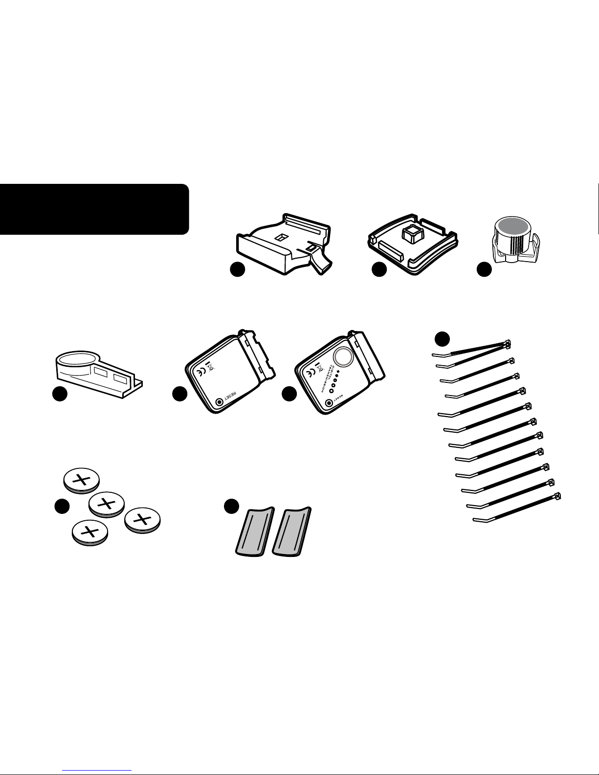
Accessories
STEP 2
3V CR2032
A
B C
D E F
G I
H
Page 5
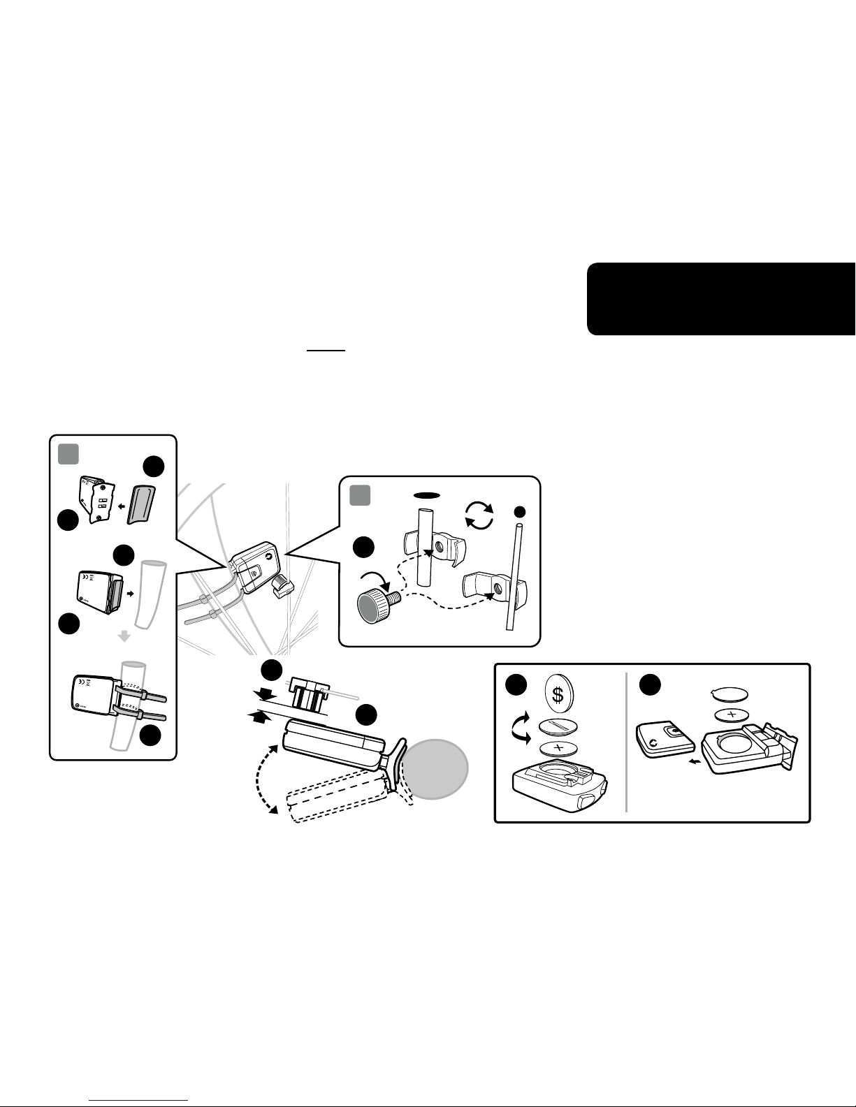
Front Wheel
Sensor
Installation
STEP 3
S
E
N
S
O
R
2
3
3V
CR2032
Clamp the magnet onto the spoke of front wheel and attach
the transmitter to the right fork (right side when you stand in
front of bicycle) by using the cable ties as shown in Fig. 2.
The silver arrow on the transmitter must face towards the
wheel.
Make sure the arc of magnet intersects the alignment arrow on
the transmitter with 2 mm clearance as shown in Fig. 3.
G G
E
C
C
H
E
E
I
I
2mm Max
Page 6
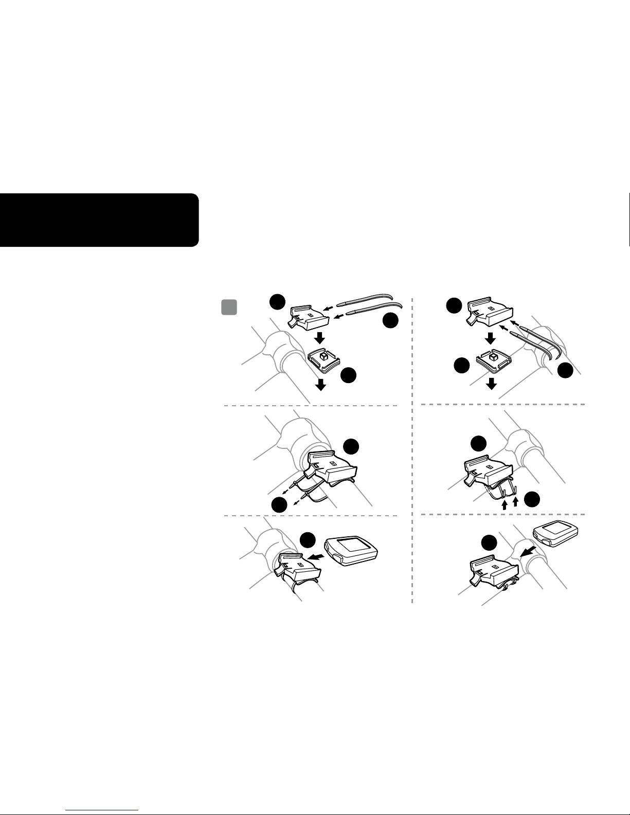
Mounting
Bracket
STEP 4
1
Handlebar Mount Stem Mount
1a
1b
1c
1a
1b
1c
A
A
A
A
A
A
B
B
H
H
H
H
Page 7
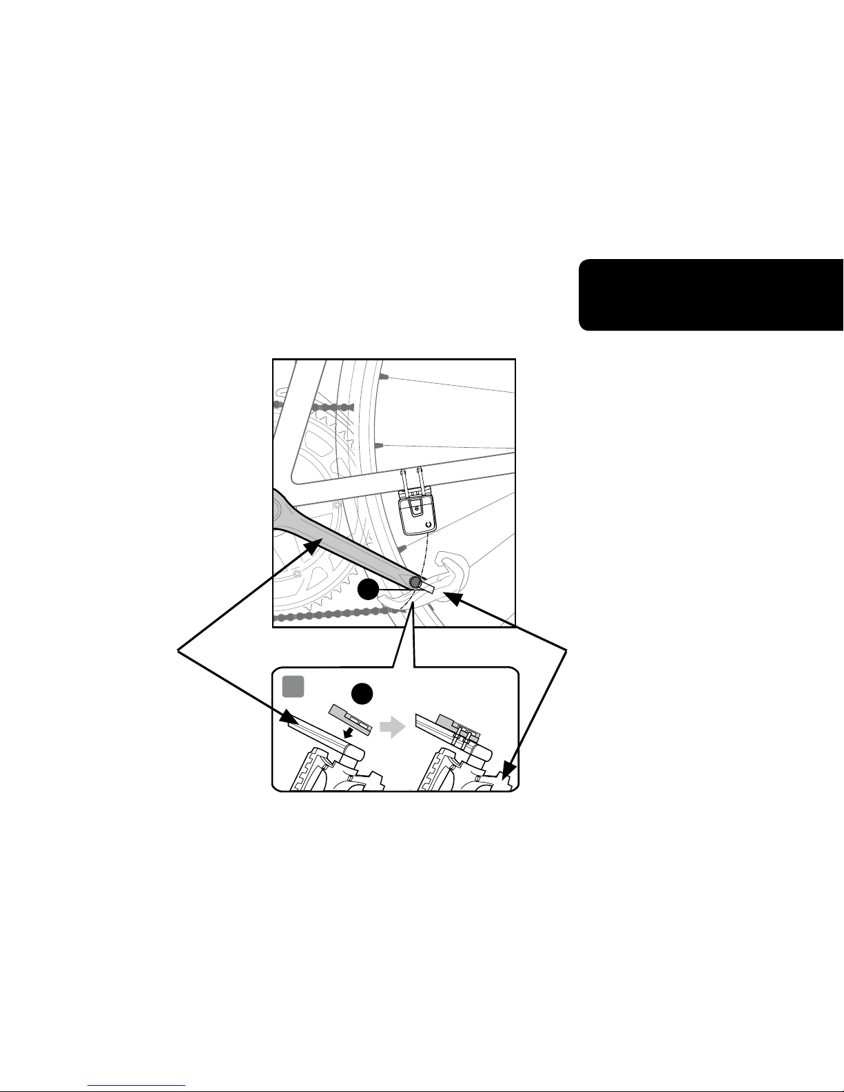
CADENCE
Magnet
Installation
STEP 5
S
E
N
S
O
R
D
5
D
Crankarm
Top view
Pedal
Page 8
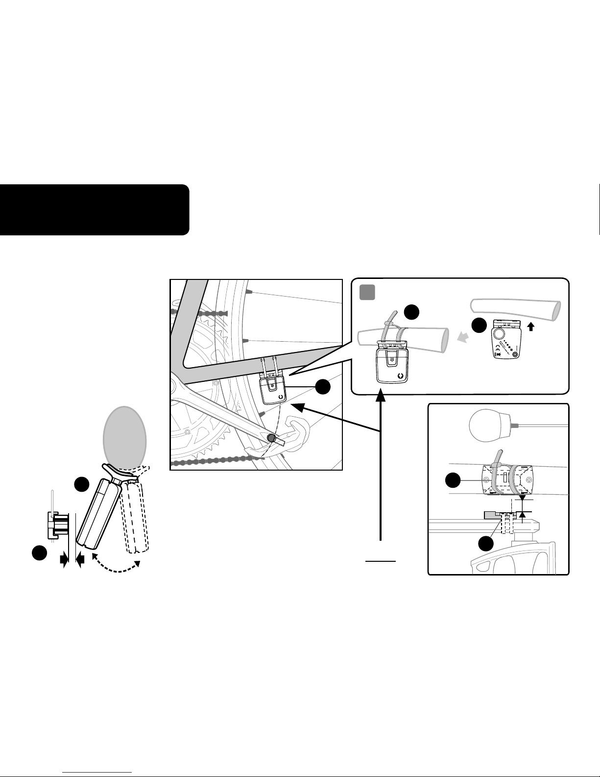
CADENCE
Sensor
Installation
STEP 6
F
D
S
E
N
S
O
R
F
4
S
E
N
S
O
R
H
F
The silver arrow on the transmitter must
face towards the crankarm.
F
D
Top
View
2mm Max
2mm Max
Page 9
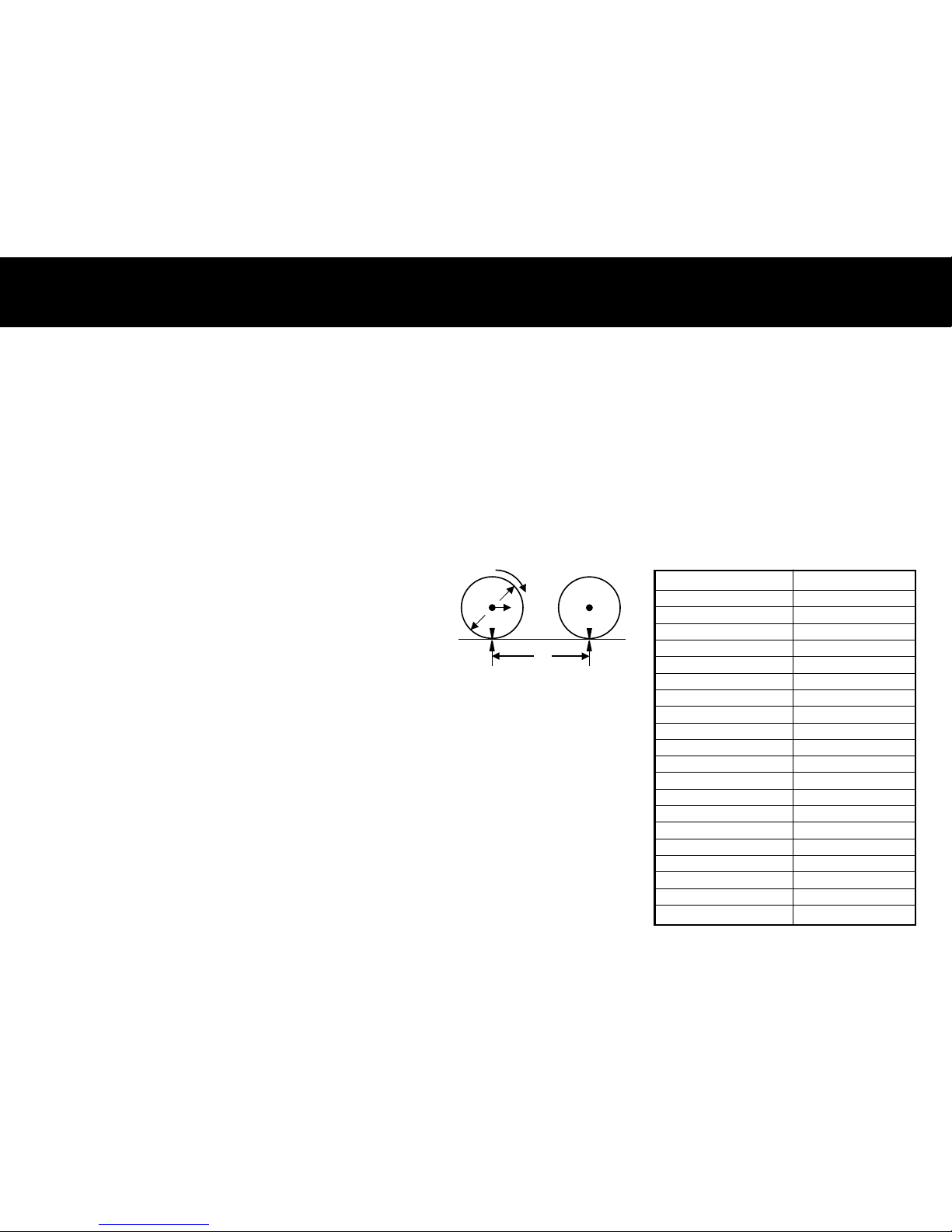
HOW TO MEASURE WHEEL FACTOR
1
2
d
xx
c
Press the Right Button to adjust the value of the rst
digit of the Wheel Factor. Once you have entered the
correct value, press the Left Button to conrm the value
and advance to the next digit. Repeat for all four digits.
Press the Left Button to advance to KM/MILE selection.
KM/MILES SELECTION: After wheel size has been input,
the Km/Miles units for distance and speed will ash.
Press the RIGHT button to choose between Kilometer
(KM) and Mile (M), press the LEFT button to conrm.
Press and hold LEFT and RIGHT buttons for
4 seconds to access wheel size input mode.
Note all information in computer will be erased.
The digits on the bottom row will ash. The
value you need to enter into the computer is
the Wheel Factor. Wheel
Factor is the circumference of the wheel in
mm. To obtain Wheel Factor:
1) Fast (and not so accurate) Method — use
chart provided.
2) Most accurate method:
a) See gure 8.
b) Inate your tires to proper pressure
c) Put a mark on the outside circumference
of your front wheel (use masking tape)
d) Put a mark on the oor.
e) Put the mark on the wheel on the mark on
the oor.
f) Rotate the wheel one full revolution until
the mark on the wheel is on the oor
again. Mark this spot on the oor.
g) Measure the distance between the marks
on the oor in mm. This is your wheel
factor (i.e. your wheel circumference).
Fig.8
distance in millimeter
per one turn
Wheel Factor C
1913
1953
2005
2010
2023
2050
2055
2068
2170
2070
2086
2096
2105
2136
2170
2145
2155
2161
2288
2326
Wheel Diameter D
26 x 1.0
26 x 1.25
26 x 1.4
26 x 1.5
26 x 1.75
26 x 1.95
26 x 2.0
26 x 2.1
26 x 2.3
700 x 18
700 x 20
700 x 23
700 x 25
700 x 28
700 x 30
27 x 1"
27 x 1 1/8"
27 x 1 1/4"
29 x 2.1
29 x 2.3
Page 10

COMPUTER FUnCTiOnS
Clock (12H/24H): A 12 or 24-hour digital clock is displayed on the
third row of the screen. After Km/mile selection in setup mode,
the 12h/24h will ash. Press the RIGHT button to switch between
the 12 and 24-hour format.
Press the LEFT button to conrm and advance to the clock mode.
Press the RIGHT button to advance the hours (hold RIGHT button
for fast advance). Press the LEFT button to conrm hours. Press
the RIGHT button to advance minutes (hold RIGHT button for fast
advance). Press LEFT button to conrm minutes and advance to
“Maintenance Required Function”.
Maintenance Required Function: On the top left hand side a
wrench icon will be displayed, just below the wrench the KM
(or miles — M) will be displayed and the top row digits will be
ashing. The digits represent the distance interval in KM (or miles)
that the wrench icon will start ashing to remind you to perform
maintenance on your bicycle. You can choose a maintenance
reminder for every 200, 400, 600 and 800 KM (or miles). If 600
KM is chosen, the wrench will ash every 600, 1200, 1800 KM (or
miles), etc. Press the LEFT button to stop the wrench ( ) from
ashing. Press LEFT button to conrm maintenance interval and
exit setup mode.
ODOMETER: To set the odometer
(ODO) after battery replacement
and wheel size setting, press RIGHT
button to advance to ODO mode
and then hold LEFT button for 5
seconds until the last digit of the
ODO is ashing. To adjust the value,
press the RIGHT button and then
press the LEFT button to conrm
and select the value. Repeat this
sequence to reach the desired
odometer value.
Page 11
COMPUTER FUnCTiOnS
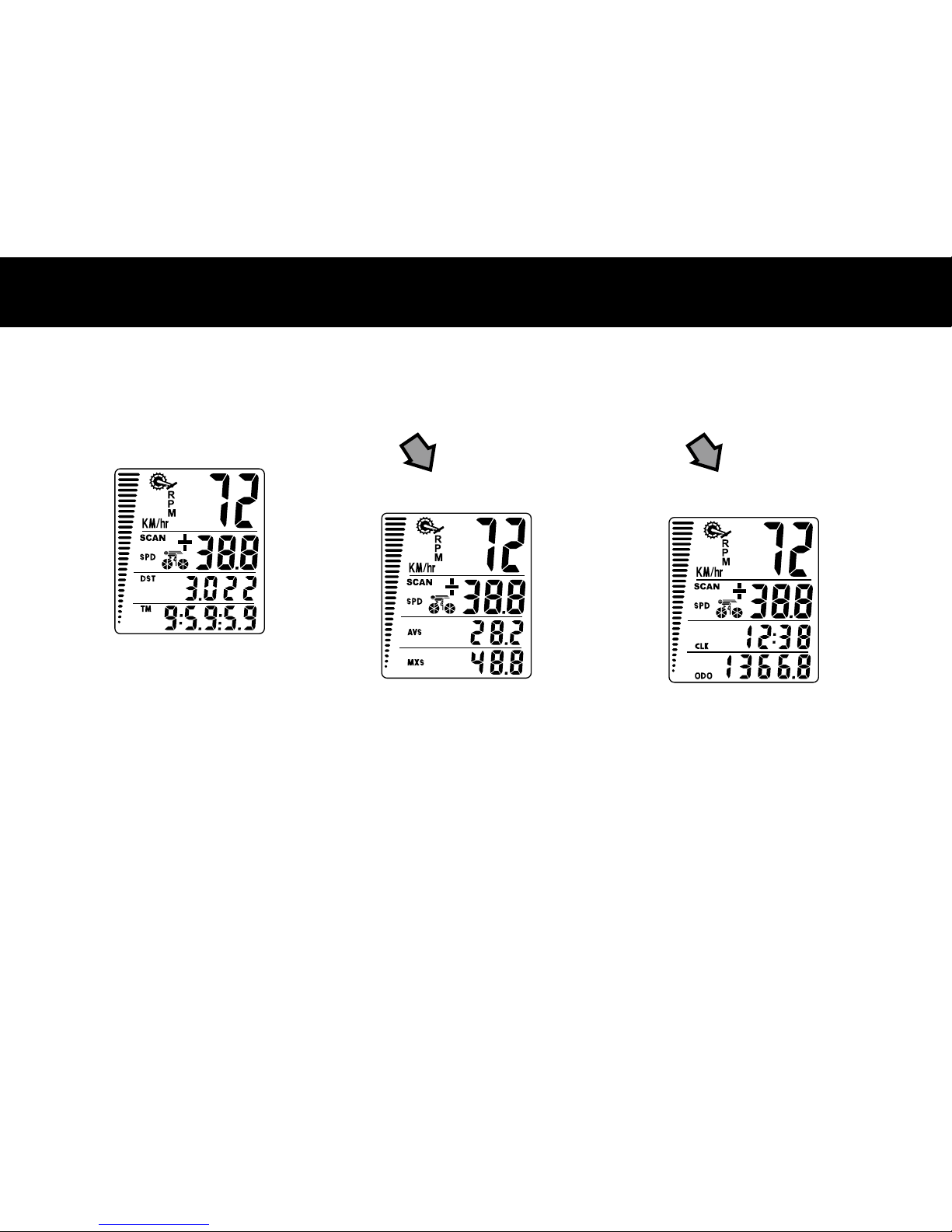
DISPLAY
There are three main screens. Press the RIGHT button to toggle between
the three display screens.
Screen 1
Cadence
(RPM)
Current Speed
(SPD)
Tripometer
(DST)
Trip Timer
(TM)
Speed Comparator
(+ or -)
Speed Tendency
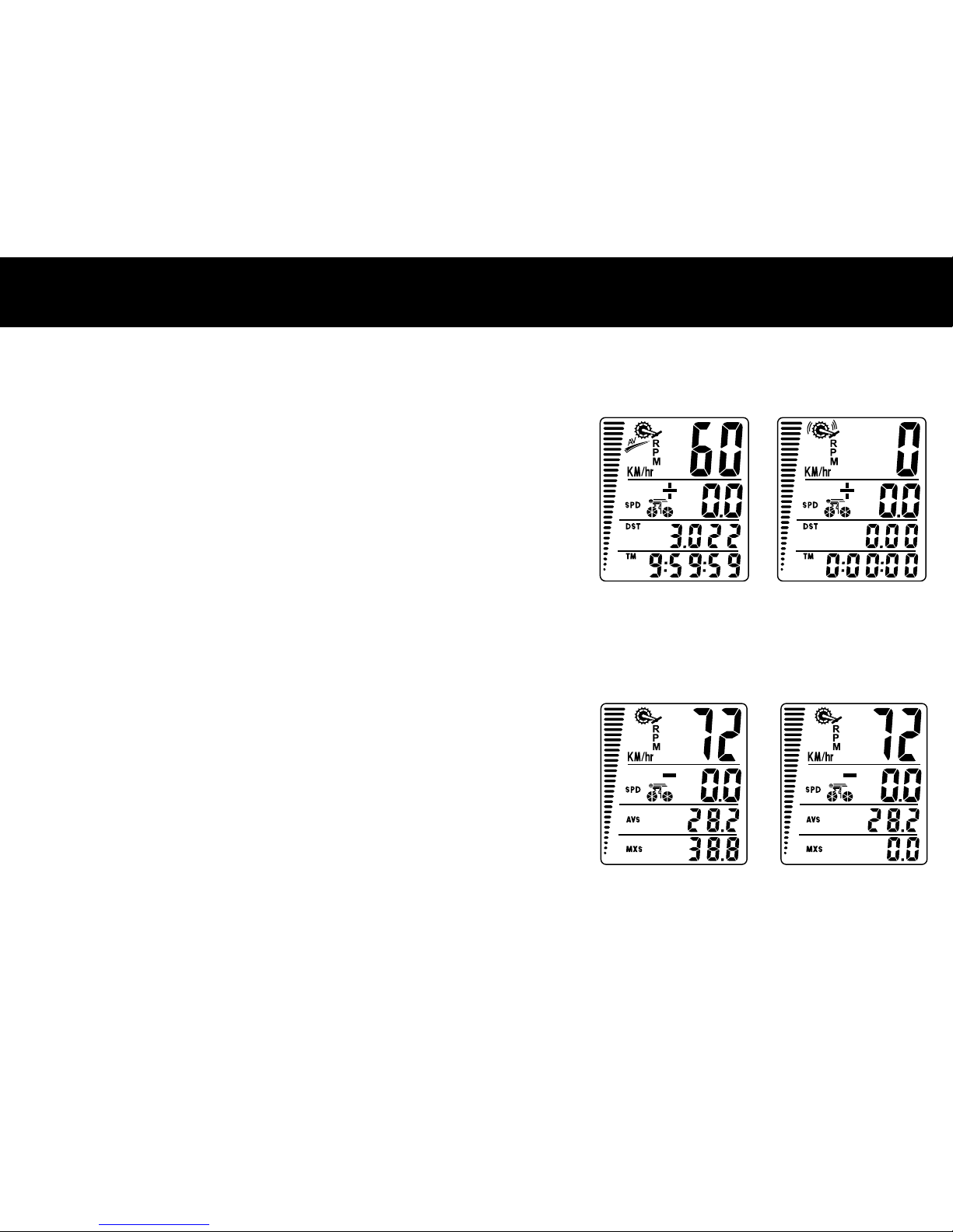
Screen 2
Cadence
(RPM)
Current Speed
(SPD)
Average Speed
(AVS)
Maximum Speed
(MXS)
Speed Comparator
(+ or -)
Speed Tendency
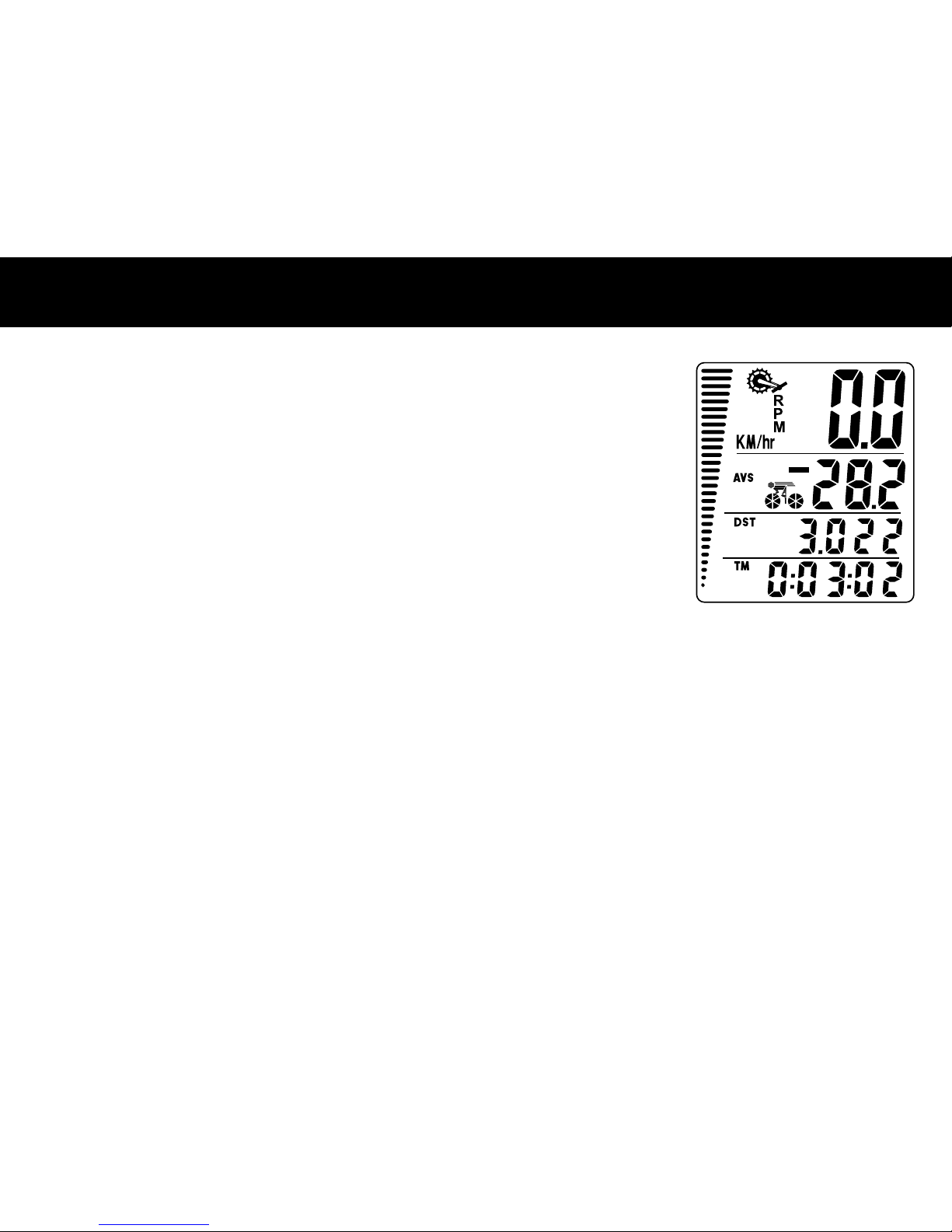
Screen 3
Cadence
(RPM)
Current Speed
(SPD)
Clock
(CLK)
Total Distance/
Odometer
(ODO)
Speed Comparator
(+ or -)
Speed Tendency
Page 12
COMPUTER FUnCTiOnS
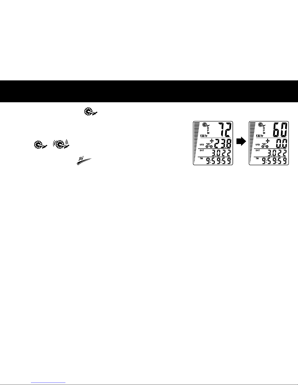
Cadence: Current Cadence ( RPM) is shown on the Top Row
of the screen.
Cadence is the rotational speed of your cranks in RPM (revolutions
per minute). When the “Brackets” around the Crank Icon are
ashing ( ) ( ) the computer is getting a Cadence signal.
To see (Average Cadence RPM) press the left button and
Average Cadence will be displayed (FLASHING) for 4 seconds.
Speed Comparator: A “+” or “-” sign appears on the second line,
to the right of the SPD icon. A “+” indicates you are traveling faster
than your average speed (AVS). A “-” indicates you are riding
slower than your average speed.
Speed Tendency (Acceleration & Deceleration): A cyclist icon
appears on the second row of the display. The wheels turn
forward to indicate acceleration, and turn backwards to indicate
deceleration.
Page 13

AddiTiOnAL FUnCTiOn MOdES
ADDITIONAL FUNCTION MODES
Maintenance Reminder Functions: The Maintenance Required
Function lets you know when you need to do scheduled
maintenance on your bicycle — for instance re-oil your chain after
a pre-set distance is reached. The Maintenance Require Icon ( )
will appear when maintenance is required.
During setup you can set the preset maintenance reminder function
to 200, 400, 600 or 800 miles (or Km). If 600 KM is chosen, the
wrench will ash every 600, 1200, 1800 KM (or miles), etc.
Press the LEFT button to stop the wrench (ICON) from ashing.
Scan Mode (SCAN): Scan mode allows you to see all screens
without pressing any button. Each screen will be displayed for
4 seconds. Press the RIGHT button until the SCAN icon is displayed
on the left hand side of the 2nd row. Press the RIGHT button to stop
SCAN mode — note SCAN mode is ON only when SCAN is shown
on the screen.
Clock (CLK): A 12/24-hour clock is displayed on the third row.
Speedometer (SPD): Instantaneous Speed is displayed in the 2nd
row. The range of measurement is from 0 to 99KM/hr (0 to 99M/hr)
and accuracy is + /-0.5KM/hr (M/hr).
Page 14
AddiTiOnAL FUnCTiOn MOdES
Odometer (ODO): Total distance traveled (ODO) is displayed on
the bottom row. To reset ODO, press and hold
LEFT and RIGHT buttons for 5 seconds or remove the battery.
Tripometer (DST): Trip distance (DST) is displayed on the third
row. Tripometer is activated automatically with speedometer
input. Reset DST (Go to DST screen — SCAN OFF) to zero by
pressing the LEFT button for 2 seconds.
NOTE: TM (Trip Time) and AVS (Average Speed) will also be reset.
Maximum Speed (MXS): Maximum Speed (MXS) is displayed
on the bottom row. Maximum speed is stored in memory and
updates only when a higher speed is reached. To reset maximum
speed, press and hold the LEFT button in the MXS display screen
for 2 seconds.
Page 15
AddiTiOnAL FUnCTiOn MOdES
Average Speed (AVS): Average Speed (AVS) is displayed on the third row.
AVS is calculated using the Trip Timer and Tripometer.
Trip Timer (TM): Trip Timer (TM) is displayed on the bottom row. Trip Timer
is activated automatically with speedometer input (when the front wheel is
turning). It records only the time spent actually riding. To reset TM to zero
press and hold the LEFT button in the TM display screen for 2 seconds.
NOTE: DST (Tripometer) and AVS (Average Speed) will also be reset.
Auto Start / Stop: To prolong battery life, the computer will automatically
switch off if the unit is left unused for more than 5 or 6 minutes. Display
will reappear with a press on either button.
Page 16

TROUBLESHOOTinG
PROBLEM SOLUTION
No Cadence Value Verify that the cadence sensor and cadence
magnet are aligned properly
Inaccurate Cadence Value Verify that the cadence sensor and cadence
magnet are aligned properly
Inaccurate maximum Speed
reading
Unknown atmospheric or RF interference
Reset Max speed
No Speedometer reading Improper magnet/transmitter alignment.
Check magnet/transmitter alignment and
verify that the wheel transmitter battery
is good.
Incorrect Speedometer
Reading
RF interference from electromagnetic
sources such as electronics, orescent
lights, high voltage wires, telephone
lines,etc.
Slow display response Temperature outside of operating limits
(32 – 125°F or 0 – 55°C)
No Trip Distance reading Improper magnet/transmitter alignment.
Check magnet/transmitter alignment and
verify that the transmitter battery is good.
Display shows irregular
gures or blank screen
Re-install computer battery and verify that
the computer battery is good.
Black Display Temperature too hot or display exposed
to direct sunlight too long.
Page 17

FONCTIONS
AVERTISSEMENT :
Suivre les instructions
avec soin. S’assurer
qu’aucune pièce
de montage de
l’ordinateur n’interfère
avec les freins ou
les roues. Inspecter
souvent les vis et les
écrous pour vérier
leur xation.
Cadence ( RPM)
Cadence moyenne ( RPM)
Indicateur de vitesse (SPD) (0 à 99,9 km/h ou miles/h)
Distance randonnée (DST) (0 à 999,99 km ou miles)
Odomètre (ODO) (jusqu’à 9 999,9 km ou miles)
Durée randonnée auto (TM) (9:59:59)
Vitesse maximum (MXS) (0 à 99,9 km/h ou miles/h)
Horloge, choix de format 12/24 heures
Vitesse moyenne (AVS) (0 à 99,9 km/h ou miles/h)
Comparateur de vitesse (+ ou -)
Tendance de la vitesse
Fonction de programmation de l’odomètre (ODO)
Balayage automatique
Fonction Entretien requis ( )
Rétroéclairage : Appuyer sur un bouton quelconque,
l’écran s’illumine pendant quelques secondes
!
Page 18

STEP 2ÉTAPE 1
Ordinateur — (Remarque : La pile est préinstallée) Enlever le
couvercle du compartiment de la pile au fond de l’ordinateur à
l’aide d’une petite pièce de monnaie.
Installer la pile de 3 V de manière à ce que le pôle positif (+)
soit orienté vers le couvercle (Figure 1a). Si l’écran LCD afche
des chiffres irréguliers, sortir la pile et la remettre en place. Ceci
remet le microprocesseur de l’ordinateur à zéro.
Pile préinstallée
Pile d’ordinateur
(3 V / CR 2032)
Fig. 1a Fig. 1b
Émetteur de roue – (Remarque : La pile est préinstallée) Installer
la pile de 12 V dans l’émetteur de roue, le pôle positif (+) orienté
vers le bouchon de la pile. Remettre le bouchon en place avec une
petite pièce de monnaie et vérier qu’il est hermétiquement fermé
pour éviter toute pénétration d’humidité (Figure 1b).
Pile d’émetteur
(12 V / VR22L)
1028 / A 23
Installation
des piles
Page 19

STEP 3ÉTAPE 2
3V CR2032
D E F
G I
H
A
B C
Accessoires
Page 20

STEP 2ÉTAPE 3
Installation du
capteur de
roue avant
Fixer l’aimant par une attache sur un rayon de la roue avant et
xer l’émetteur sur la fourche (sur la jambe droite de la fourche
quand vous vous tenez en face de la bicyclette) à l’aide des
attaches de câble, selon l’illustration de la Fig. 2.
La èche argentée sur l’émetteur doit faire face à la roue.
Vérier que l’arc de l’aimant intersecte le repère d’alignement
sur l’émetteur avec un jeu de 2 mm comme illustré à la Fig. 3.
S
E
N
S
O
R
2
3
3V
CR2032
G G
E
C
C
H
E
E
I
I
2mm Max
Page 21

STEP 3ÉTAPE 4
Support
de montage
1
1a
1b
1c
1a
1b
1c
A
A
A
A
A
A
B
B
H
H
H
Montage sur le guidon Montage sur la tige
H
Page 22

STEP 2ÉTAPE 5
Installation du
l’aimant de
CADENCE
S
E
N
S
O
R
D
5
D
Bras du pédalier
Pédale
Vue de dessus
Page 23

STEP 3ÉTAPE 6
Installation du
capteur de
CADENCE
F
D
S
E
N
S
O
R
F
4
S
E
N
S
O
R
H
F
2mm Max
F
D
2mm Max
La èche argentée sur l’émetteur doit faire
face au bras du pédalier.
Vue
de
dessus
Page 24

Appuyer sur les boutons GAUCHE et DROIT
pendant 4 secondes pour accéder au mode de
saisie de la dimension de roue.
À noter que toutes les informations en mémoire
dans l’ordinateur seront effacées.
Les chiffres de la ligne du bas clignotent. La
valeur qu’il faut saisir dans l’ordinateur est le
Facteur de dimension de la roue :
1) Méthode rapide (avec précision
approximative) – utiliser le tableau fourni.
2) Méthode plus précise :
a) Voir la Figure 8.
b) Goner les pneus à la pression adéquate
c) Marquer un repère sur l’extérieur de la
circonférence de la roue avant (à l’aide de
ruban de masquage)
d) Marquer un repère sur le sol.
e) Faire coïncider le repère de la roue et le
repère du sol.
f) Faire tourner la roue sur un tour complet
jusqu’à ce que le repère de la roue soit
de nouveau en contact avec le sol. Marquer
ce deuxième point de repère sur le sol.
g) Mesurer la distance entre les deux points de repère du sol en
millimètres. Ceci est votre facteur de dimension de roue (c.-à-d., la
longueur de la circonférence de la roue).
Appuyer sur le bouton Droit pour ajuster la valeur du
premier chiffre du facteur de dimension de roue. Quand
la valeur correcte a été saisie, appuyer sur le bouton
Gauche pour conrmer et avancer jusqu’au chiffre
suivant. Recommencer ce réglage pour les quatre
chiffres. Appuyer sur le bouton Gauche pour avancer
jusqu’à l’option KM/MILES.
SÉLECTION KM/MILES : Quand la dimension de roue a
été saisie, les unités de distance en km/mile se mettent
à clignoter.
Appuyer sur le bouton
DROIT pour choisir les
kilomètres (KM) ou les
miles (M), puis appuyer
sur le bouton GAUCHE
pour conrmer.
COMMEnT MESURER LE FACTEUR dE diMEnSiOn dE LA ROUE
Facteur de roue C
1913
1953
2005
2010
2023
2050
2055
2068
2170
2070
2086
2096
2105
2136
2170
2145
2155
2161
2288
2326
Diamètre de roue D
26 x 1.0
26 x 1.25
26 x 1.4
26 x 1.5
26 x 1.75
26 x 1.95
26 x 2.0
26 x 2.1
26 x 2.3
700 x 18
700 x 20
700 x 23
700 x 25
700 x 28
700 x 30
27 x 1"
27 x 1 1/8"
27 x 1 1/4"
29 x 2.1
29 x 2.3
1
2
d
xx
c
Fig.8
Distance en millimètres
pour un tour
Page 25

FOnCTiOnS dE L’ORdinATEUR
Horloge (12H/24H) : Une horloge numérique de format 12 ou 24
heures est afchée sur la 3ème ligne de l’écran. Après la sélection
du mode km/miles en mode conguration, l’afchage 12H/24H
se met à clignoter. Appuyer sur le bouton DROIT pour passer du
format 12 heures au format 24 heures.
Appuyer sur le bouton GAUCHE pour conrmer et avancer
jusqu’au mode Horloge.
Appuyer sur le bouton DROIT pour avancer jusqu’aux heures
(maintenir le bouton DROIT enfoncé pour avancer plus vite).
Appuyer sur le bouton GAUCHE pour conrmer les heures.
Appuyer sur le bouton DROIT pour avancer jusqu’aux minutes
(maintenir le bouton DROIT enfoncé pour avancer plus vite).
Appuyer sur le bouton GAUCHE pour conrmer et avancer jusqu’à
la “Fonction d’entretien requise.”
Fonction Entretien requis : Dans le coin supérieur gauche une icône
de clé anglaise s’afche, et juste au-dessous de la clé, les KM (ou miles – M)
s’afchent et les chiffres de la ligne supérieure se mettent à clignoter. Les
chiffres représentent la distance en KM (ou miles) sur laquelle l’icône de
clé anglaise clignotera pour vous rappeler d’effectuer l’entretien de votre
bicyclette. On peut choisir comme intervalle d’entretien tous les 200, 400,
600 et 800 KM (ou miles). Si l’on choisit 600 KM, la clé anglaise clignotera
tous les 600, 1200, 1800 KM (ou miles), etc. Appuyer sur le bouton GAUCHE
pour arrêter le clignotement de la clé anglaise ( ). Appuyer sur le bouton
GAUCHE pour conrmer l’intervalle d’entretien et sortir du mode conguration.
mantenimiento y salir del modo de conguración.
ODOMÈTRE : Pour congurer
l’odomètre (ODO) après le
remplacement de la pile et la
conguration de la dimension de
roue, appuyer sur le bouton DROIT
pour avancer jusqu’au mode ODO,
puis maintenir le bouton GAUCHE
enfoncé pendant 5 secondes jusqu’à
ce que le dernier chiffre de l’ODO se
mette à clignoter. Pour régler la valeur,
appuyer sur le bouton DROIT, puis
appuyer sur le bouton GAUCHE pour
conrmer et choisir la valeur. Répéter
cette séquence jusqu’à atteindre la
valeur souhaitée pour l’odomètre.
Page 26

FOnCTiOnS dE L’ORdinATEUR
AFFICHAGE
Il y a trois écrans principaux. Appuyer sur le bouton DROIT pour
passer d’un écran d’afchage à l’autre.
Écran 3
Cadence
(RPM)
Vitesse courante
(SPD)
Clock (horloge)
(CLK)
Distance totale/odomètre
(ODO)
Comparateur de vitesse
(+ ou -)
Tendance de la vitesse
Écran 2
Cadence
(RPM)
Vitesse courante
(SPD)
Vitesse moyenne
(AVS)
Vitesse maximum
(MXS)
Comparateur de vitesse
(+ ou -)
Tendance de la vitesse
Écran 1
Cadence
(RPM)
Vitesse courante
(SPD)
Distance du parcours
(DST)
Durée du parcours
(TM)
Comparateur de vitesse
(+ ou -)
Tendance de la vitesse
Page 27

STEP 3
FOnCTiOnS dE L’ORdinATEUR
Cadence : La cadence courante ( RPM) est indiquée
sur la ligne supérieure de l’écran.
La cadence est la vitesse de rotation des manivelles du
pédalier en RPM (tours/minute). Quand les parenthèses
entourant l’icône Pédalier clignotent ( ) ( )
l’ordinateur reçoit le signal de cadence.
Pour observer la cadence moyenne ou Average Cadence
( RPM) appuyer sur le bouton Gauche et les mots
Average Cadence (cadence moyenne) s’afchent (EN
CLIGNOTANT) pendant 4 secondes.
Comparateur de vitesse : Un signe “+” ou “-” apparaît sur la
deuxième ligne, à droite de l’icône SPD. Un signe “+” signie
que vous roulez plus vite que la vitesse moyenne (AVS). Un
signe “-” signie que vous roulez plus lentement que votre
vitesse moyenne.
Tendance de la vitesse (accélération et décélération) : Une
icône de cycliste apparaît sur la deuxième ligne de l’afchage.
Les roues tournent en avant pour indiquer l’accélération et
elles tournent en arrière pour indiquer la décélération.
Page 28

MOdES FOnCTiOnnELS SUPPLEMEnTAiRES
Fonctions de rappel du besoin d’entretien : La fonction Entretien requis
vous informe que vous avez besoin d’effectuer l’entretien régulier de votre
bicyclette – par exemple, graisser la chaîne après avoir parcouru une
certaine distance. L’icône Entretien requis ( ) apparaît quand un besoin
d’entretien se manifeste.
Pendant la conguration, il est possible de précongurer la fonction de
rappel d’entretien à 200, 400, 600 ou 800 km (ou miles). Si l’on choisit 600
km, la clé anglaise clignote tous les 600, 1200, 1800 km (ou miles), etc.
Appuyer sur the bouton GAUCHE pour arrêter le clignotement de la clé
anglaise ( ).
Mode Balayage (SCAN) : le mode balayage permet de voir tous les
écrans sans appuyer sur aucun bouton. Chaque écran s’afche pendant
4 secondes. Appuyer sur le bouton DROIT jusqu’à ce que l’icône SCAN
s’afche à gauche sur la 2ème ligne. Appuyer sur le bouton DROIT pour
arrêter le mode balayage — À noter que le mode balayage SCAN est activé
seulement lorsque SCAN s’afche sur l’écran.
Horloge (CLK) : Une horloge afchant l’heure dans le format 12/24 heures
s’afche sur la troisième ligne.
Indicateur de vitesse (SPD) : La vitesse instantanée (Instantaneous Speed)
est afchée sur la 2ème ligne. La plage des mesures est comprise entre 0 et
99 km/h (0 à 99 M/h) et la précision est de + /- 0,5 km/h (M/h).
Page 29

MOdES FOnCTiOnnELS SUPPLEMEnTAiRES
Odomètre (ODO) : La distance totale parcourue (ODO) est
afchée sur la ligne du bas. Pour réinitialiser l’ODO, appuyer
sur les boutons GAUCHE et DROIT pendant 5 secondes ou
enlever la pile.
Distance randonnée (DST) : La distance de la randonnée
(DST) est afchée sur la troisième ligne. L’indicateur de
distance de la randonnée (DST) est activé automatiquement
lors de la saisie de l’indicateur de vitesse. Réinitialiser
l’indicateur DST (aller à l’écran DST – balayage (SCAN)
désactivé) pour le remettre à zéro en appuyant sur le bouton
GAUCHE pendant 2 secondes.
REMARQUE : Les fonctions TM (Durée de la randonnée) et
AVS (Vitesse moyenne) seront également réinitialisées.
Vitesse maximum (MXS) : La vitesse maximum (MXS)
est afchée sur la ligne du bas. La vitesse maximum est
enregistrée en mémoire et se met à jour uniquement lorsqu’on
atteint une vitesse supérieure. Pour remettre la vitesse
maximum à zéro, appuyer sur le bouton GAUCHE et le laisser
enfoncé pendant 2 secondes lorsque l’écran MXS est afché.
Page 30

MOdES FOnCTiOnnELS SUPPLEMEnTAiRES
Vitesse moyenne (AVS) : La vitesse moyenne (AVS) s’afche sur
la troisième ligne.
L’AVS est calculée à l’aide de l’indicateur de durée et
l’indicateur de distance de la randonnée.
Durée randonnée (TM) : La durée de la randonnée (TM)
est afchée sur la ligne du bas. L’indicateur de durée de la
randonnée est activé automatiquement avec la saisie de
l’indicateur de vitesse (quand la roue avant tourne). Il enregistre
seulement la durée effective de roulement. Pour remettre
l’indicateur TM à zéro, appuyer sur le bouton GAUCHE et le
laisser enfoncé pendant 2 secondes lorsque l’écran TM est
afché.
REMARQUE : Les fonctions DST (Distance de la randonnée) et
AVS (Vitesse moyenne) seront également réinitialisées.
Démarrage / Arrêt automatique : Pour prolonger la durée de
service de la pile, l’ordinateur s’arrête automatiquement si l’unité
reste inutilisée pendant plus de 5 ou 6 minutes. L’afchage
réapparaît quand on appuie sur un bouton quelconque.
Page 31

dEPAnnAGE
PROBLÈME SOLUTION
Aucune valeur de cadence Vérier que le capteur de cadence et l’aimant
de cadence sont correctement alignés
Valeur de cadence inexacte Vérier que le capteur de cadence et l’aimant
de cadence sont correctement alignés
Lecture inexacte de la vitesse
maximum
Interférence atmosphérique ou en RF
inconnue Recongurer la vitesse maximum
Aucune valeur n’apparaît dans
l’indicateur de vitesse
Alignement aimant/émetteur incorrect.
Vérier l’alignement de l’aimant et de
l’émetteur et le bon état de la pile de
l’émetteur de roue.
Lecture inexacte de
l’indicateur de vitesse
Interférence en RF provenant de sources
électromagnétiques telles que des appareils
électroniques, des éclairages uorescents,
des câbles haute tension, des lignes
téléphoniques, etc.
Afchage lent à répondre La température est hors des limites
fonctionnelles 0° à 55 °C ou (32° à 125 °F)
Aucune lecture de distance de
la randonnée
Alignement aimant/émetteur incorrect.
Vérier l’alignement de l’aimant et de
l’émetteur et le bon état de la pile de
l’émetteur de roue.
L’afchage indique des
chiffres irréguliers ou des
écrans en blanc
Réinstaller la pile de l’ordinateur et vérier
qu’elle est en bon état.
Afchage en noir Température trop élevée ou afchage exposé
trop longtemps à la lumière directe du soleil.
Page 32

FUNCIONES
ADVERTENCIA:
Siga las instrucciones
cuidadosamente.
Asegúrese que
ninguna pieza del
ensamblaje del
ciclocomputador
interera con los
frenos o ruedas.
Verique las tuercas
y pernos a menudo
para asegurarse que
estén apretados.
Cadencia ( RPM)
Cadencia promedio ( RPM)
Velocímetro (SPD (0 a 99,9 km/h o millas/h – M/h)
Distancia recorrida (DST) (0 a 999,99 km o millas (M))
Odómetro (ODO) (hasta 9999,9 km o millas (M))
Temporizador automático de recorrido (TM) (9:59:59)
Velocidad máxima (MXS) 0 a 99,9 km/h o millas/h – M/h)
Reloj, seleccionable entre 12/24 horas
Velocidad promedio (AVS) (0 a 99,9 km/h o millas/h – M/h)
Comparador de velocidad (+ o -)
Tendencia de velocidad
Función de programación de odómetro (ODO)
Autoexplorar
Funciones de mantenimiento necesario ( )
Retroiluminación: pulse cualquier botón, la lámpara
se encenderá durante unos cuantos segundos
!
Page 33

Computador – (Nota: la pila se presenta preinstalada) Quite la
tapa de la pila del fondo del computador mediante el uso de
una moneda pequeña. Instale la pila de 3V con el polo positivo
(+) dirigido hacia la tapa (Figura 1a). Si el LCD muestra guras
irregulares, desmonte la pila y vuelva a instalarla. Esto despejará
y volverá a arrancar el microprocesador del computador.
La pila se presenta preinstalada
Pila del computador
(3V / CR2032)
Fig. 1a Fig. 1b
Transmisor de la rueda – (Nota: la pila se presenta preinstalada)
Instale la pila de 12V en el transmisor de la rueda con el polo positivo
(+) dirigido hacia la tapa de la pila. Vuelva a instalar la tapa con una
pequeña moneda y asegúrese que esté apretada para evitar la entrada
de humedad (Figura 1b).
PASO 1
Pila del transmisor
(12V / VR22L
1028 / A 23)
Instale Baterías
Page 34

STEP 2
Accesorios
PASO 2
3V CR2032
A
B C
D E F
G I
H
Page 35

STEP 3
Instalación
del sensor
de la rueda
delantera
PASO 3
.
Sujete el imán sobre el rayo de la rueda delantera y je el
transmisor a la horquilla derecha (el lado derecho cuando usted
se encuentre frente a la bicicleta) mediante el uso de bridas/
abrazaderas plásticas tal como se muestra en la Fig. 2.
La echa plateada en el transmisor debe mirar hacia la rueda.
Asegúrese que el arco del imán se interseca con la marca de
alineación en el transmisor con una holgura de 2 mm, tal como
se muestra en la Fig. 3.
S
E
N
S
O
R
2
3
3V
CR2032
G G
E
C
C
H
E
E
I
I
2mm Max
Page 36

STEP 2
Soporte
de montaje
PASO 4
1
1a
1b
1c
1a
1b
1c
A
A
A
A
A
A
B
B
H
H
H
H
Montura en el manillar/manubrio Montura sobre el poste
Page 37

STEP 3
Instalación
del imán de
CADENCIA
PASO 5
.
S
E
N
S
O
R
D
5
D
Manivela
Pedal
Vista superior
Page 38

STEP 2
Instalación
del sensor de
CADENCIA
PASO 6
F
D
S
E
N
S
O
R
F
4
S
E
N
S
O
R
H
F
F
D
Vista
superior
2mm Max
2mm Max
La echa plateada en el transmisor debe
mirar hacia la manivela.
Page 39

CÓMO MEdiR EL FACTOR dE LA RUEdA
Pulse y mantenga pulsado los botones
IZQUIERDO y DERECHO durante cuatro (4)
segundos para acceder el modo de ingresar el
tamaño de la rueda. Tenga en cuenta que se
borrará toda la información en el computador.
Los dígitos en la hilera inferior se iluminarán
intermitentemente.
El valor que usted requiere ingresar en el
computador es el Factor de la rueda. El Factor
de la rueda es la circunferencia de la rueda en
mm. Para obtener el Factor de la rueda:
1) Método rápido (mas no muy preciso)—
utilice el cuadro provisto.
2) El método más preciso:
a) Vea la Figura 8.
b) Hinche/Ine las ruedas a la presión correcta.
c) Coloque una marca en la circunferencia exterior
de su rueda delantera (use cinta aislante).
d) Ponga una marca en el piso.
e) Coloque la marca en la rueda sobre la marca
en el piso.
f) Gire la rueda una revolución completa hasta que
la marca en rueda vuelva a tocar el piso. Marque este punto en el piso.
g) Mida la distancia entre las marcas en el piso en milímetros. Este es su
Factor de rueda (en otras palabras, la circunferencia de su rueda).
Pulse el Botón derecho para ajustar el valor del primer
dígito del Factor de la rueda. Una vez que haya
ingresado el valor correcto, pulse el Botón izquierdo
para conrmar el valor y avanzar al siguiente dígito.
Repita para todos los cuatro dígitos.
Pulse el Botón izquierdo para avanzar a la selección
de km/millas. SELECCIÓN DE KM/MILLAS: una
vez ingresado el tamaño de la rueda, se iluminarán
intermitentemente las unidades de distancia y velocidad
en km/millas. Pulse el botón DERECHO para escoger
entre Kilómetros (km) y
Millas (M); pulse el
botón IZQUIERDO
para conrmar.
Distancia en
milímetros de una
vuelta completa
1
2
d
xx
c
Fig.8
Factor de la rueda C
1913
1953
2005
2010
2023
2050
2055
2068
2170
2070
2086
2096
2105
2136
2170
2145
2155
2161
2288
2326
Diámetro de la rueda D
26 x 1.0
26 x 1.25
26 x 1.4
26 x 1.5
26 x 1.75
26 x 1.95
26 x 2.0
26 x 2.1
26 x 2.3
700 x 18
700 x 20
700 x 23
700 x 25
700 x 28
700 x 30
27 x 1"
27 x 1 1/8"
27 x 1 1/4"
29 x 2.1
29 x 2.3
Page 40

FUnCiOnES dEL COMPUTAdOR
Reloj (12 h/24 h): aparecerá un reloj digital de 12 o 24 horas en la
tercera hilera de la pantalla. Después de haber hecho la selección
de km/millas en el modo de conguración, la indicación de 12 h/24
h se iluminará intermitentemente. Pulse el botón DERECHO para
transferir entre el formato de 12 horas y de 24 horas.
Pulse el botón IZQUIERDO para conrmar y avanzar al modo de
reloj. Pulse el botón DERECHO para avanzar las horas (mantenga
pulsado el botón DERECHO para avanzar rápidamente). Pulse
el botón IZQUIERDO para conrmar las horas. Pulse el botón
DERECHO para avanzar los minutos (mantenga pulsado el
botón DERECHO para avanzar rápidamente). Pulse el botón
IZQUIERDO para conrmar los minutos y avanzar a la función
de “Mantenimiento necesario”.
Función de mantenimiento necesario: en la parte superior
izquierda aparecerá el icono de “llave”, justamente debajo de
la llave aparecerá la indicación de KM (o de millas – M) y los
dígitos de la hilera superior se iluminarán intermitentemente.
Los dígitos representan el intervalo de distancia en KM (o millas)
donde el icono de llave empezará a iluminarse intermitentemente
para recordarle a uste que debe realizar el mantenimiento de su
bicicleta. Usted puede escoger un recordatorio de mantenimiento
para cada 200, 400, 600 y 800 KM (o millas), etc. Pulse el botón
IZQUIERDO para detener la iluminación intermitente de la llave
( ). Pulse el botón IZQUIERDO para conrmar el intervalo de
mantenimiento y salir del modo de conguración.
ODÓMETRO: para congurar
el odómetro (ODO) después de
reemplazar la pila y de jar el
tamaño de la rueda, pulse el botón
DERECHO para avanzar al modo de
ODO y luego mantenga pulsado el
botón IZQUIERDO durante cinco (5)
segundos hasta que el último dígito
de ODO se ilumine intermitentemente.
Para ajustar el valor, pulse el botón
DERECHO y luego pulse el botón
IZQUIERDO para conrmar y escoger
el valor. Repita esta secuencia para
lograr el valor deseado del odómetro.
Page 41

FUnCiOnES dEL COMPUTAdOR
VISUALIZACIÓN
Se tienen tres pantallas principales. Pulse el botón DERECHO
pasar de una a otra de las tres pantallas de visualización.
Pantalla 3
Cadencia
(RPM)
Velocidad actual
(SPD)
Reloj
(CLK)
Distancia total/odómetro
(ODO)
Comparador de velocidad
(+ o -)
Tendencia de velocidad
Pantalla 2
Cadencia
(RPM)
Velocidad actual
(SPD)
Velocidad promedio
(AVS)
Velocidad máxima
(MXS)
Comparador de velocidad
(+ o -)
Tendencia de velocidad
Pantalla 1
Cadencia
(RPM)
Velocidad actual
(SPD)
Distancia recorrida
(DST)
Temporizador de recorrido
(TM)
Comparador de velocidad
(+ o -)
Tendencia de velocidad
Page 42

FUnCiOnES dEL COMPUTAdOR
Cadencia: se muestra la Cadencia actual ( RPM) en
la Hilera superior de la pantalla. Cadencia es la velocidad
rotacional de los giros de las bielas en RPM (revoluciones por
minuto). Cuando los “corchetes” alrededor del ícono de Biela
se iluminan intermitentemente ( ) ( ), el computador
está recibiendo señales de cadencia.
Para ver la Cadencia promedio RPM) pulse el botón
izquierdo y se visualizará la Cadencia promedio (ILUMINADA
INTERMITENTEMENTE) durante 4 Segundos.
Comparador de velocidad: aparece una señal de “+” o de “-” en
la segunda línea a la derecha del icono de SPD (Velocidad actual).
Un “+” indica que usted viaja a mayor velocidad que su velocidad
promedio (AVS). Un “-” indica que usted viaja a una velocidad más
lenta que su velocidad promedio.
Tendencia de velocidad (Aceleración y Desaceleración): un icono de
ciclista aparece en la segunda hilera de la visualización. Las ruedas
giran hacia delante para indicar aceleración, y giran hacia atrás para
indicar desaceleración.
Page 43

MOdOS AdiCiOnALES dE FUnCiÓn
Función de recordatorio de mantenimiento: la Función de mantenimiento
necesario le deja saber a usted cuándo necesita usted hacer el
mantenimiento programado de su bicicleta, por ejemplo, volver a aceitar
su cadena después de haber logrado una distancia preestablecida. El
icono de Mantenimiento necesario ( ) aparecerá cuando se requiera
el mantenimiento.
Durante el proceso de conguración, usted puede jar la función de
recordatorio de mantenimiento preestablecido a 200, 400, 600 u 800 km
(o millas). Si se selecciona 600 km, la llave se iluminará intermitentemente
a los 600, 1200 o 1800 km (o millas), etc. Pulse el botón IZQUIERDO para
detener la iluminación intermitente del icono de la llave ( ).
Modo de Explorar (SCAN): el modo de Explorar le permite a usted ver todas
las pantallas sin pulsar botón alguno. Se podrá visualizar cada pantalla
durante cuatro (4) segundos. Pulse el botón DERECHO hasta que el icono
de SCAN aparece en el lado izquierdo de la segunda hilera. Pulse el botón
DERECHO para detener el modo de SCAN; observe que el modo de SCAN
está ACTIVADO (en ON) únicamente cuando se muestra SCAN en la pantalla.
Reloj (CLK): en la tercera hilera se visualiza un reloj de 12/24 horas.
Velocímetro (SPD): en la segunda hilera se visualiza la Velocidad instantánea.
El rango de medición es de 0 a 99 km/h (0 a 99 millas (M)/h), y la precisión
es de +/- 0,5 km/h (0,5 M/h).
Page 44

MOdOS AdiCiOnALES dE FUnCiÓn
Odómetro (ODO): en la hilera inferior se visualiza la distancia
total viajada (ODO). Para restaurar ODO, pulse y mantenga
pulsados los botones IZQUIERDO y DERECHO durante cinco
(5) segundos o desmonte la pila.
Distancia recorrida – tripometer (DST): la distancia recorrida
(DST) se visualiza en la tercera hilera. La Distancia recorrida
se activa automáticamente con el aporte del velocímetro.
Restaure DST a cero (pase a la pantalla DST – SCAN
APAGADO (OFF)) al pulsar el botón IZQUIERDO durante dos
(2) segundos.
NOTA: Se restaurarán tanto TM (Temporizador de recorrido)
como AVS (Velocidad promedio).
Velocidad máxima (MXS): la Velocidad máxima (MXS)
se visualiza en la hilera inferior. La velocidad máxima se
almacena en memoria y se actualiza únicamente cuando
se logra una velocidad más alta. Para restaurar la velocidad
máxima, pulse y mantenga pulsado el botón IZQUIERDO en
la pantalla de visualización de MXS durante dos (2) segundos.
Page 45

MOdOS AdiCiOnALES dE FUnCiÓn
Velocidad promedio (AVS): se visualiza la Velocidad promedio
(AVS) en la tercera hilera. AVS se calcula a partir del
Temporizador de viaje y la Distancia recorrida (tripometer).
Temporizador de viaje (TM): el Temporizador de viaje (TM) se
visualiza en la última hilera. El Temporizador de viaje se activa
automáticamente a partir del aporte del velocímetro (cuando
la rueda delantera gira). Registra únicamente el tiempo que
realmente se viaja en bicicleta. Para restaurar TM a cero, pulse
y mantenga pulsado el botón IZQUIERDO en la pantalla de
visualización de TM, durante dos (2) segundos.
NOTA: Se restaurarán tanto DST (Distancia recorrida) como AVS
(Velocidad promedio).
Inicio / desconexión automáticos: para prolongar la vida
de servicio de la pila, el computador automáticamente
desconectará la unidad si se deja de usar durante más de cinco
(5) o seis (6) minutos. La pantalla se volverá a encender al pulsar
uno u otro botón.
Page 46

LOCALiZACiÓn dE AVERÍAS
PROBLEMA SOLUCIÓN
No hay valor de cadencia Verique que el sensor de cadencia y el imán
de cadencia estén correctamente alineados.
Valor de cadencia inexacto Verique que el sensor de cadencia y el imán
de cadencia estén correctamente alineados.
Lectura de velocidad máxima
inexacta
Interferencia atmosférica o de
radiofrecuencia (RF) desconocida.
Restaurar la Velocidad máxima.
No hay lectura de velocímetro Alineación incorrecta de imán/transmisor.
Revise la alineación del imán/transmisor
y verique que la pila del transmisor de la
rueda funcione correctamente.
Lectura incorrecta del
velocímetro
Interferencia de RF de fuentes
electromagnéticas tales como aparatos
electrónicos, lámpara uorescentes, cables
de alta tensión, líneas telefónicas, etc.
Respuesta lenta de la pantalla Temperatura fuera de los límites de
funcionamiento (0-55°C o 32-125°F).
No hay lectura de Distancia
recorrida
Alineación incorrecta de imán/transmisor.
Revise la alineación del imán/transmisor
y verique que la pila del transmisor de la
rueda funcione correctamente.
La pantalla muestra guras
irregulares o está en blanco
Vuelva a instalar la pila del computador y
verique que la pila del computador funcione
correctamente
Pantalla negra Temperatura muy alta o pantalla expuesta
a la luz solar directa durante demasiado
tiempo.
Page 47

Page 48

7015633 / 7019882 / 7015632 / 7019886
 Loading...