

Bell BHT-206L3-FM-1 LongRanger-III Flight Manual
MODEL
206L3
ROTORCRAFT
FLIGHT MANUAL
BHT-206L3-FM-1
BHT 51001 THROUGH 51612
THIS MANUAL SHALL BE IN THE HELICOPTER DURING ALL OPERATIONS
COPYRIGHT NOTICE
COPYRIGHT
®
HELICOPTER TEXTRON INC.
BELL
AND BELL HELICOPTER TEXTRON
CANADA LTD.
ALL RIGHTS RESERVED
2005
28 OCTOBER 1992
REVISION 6 — 26 APRIL 2005

BHT-206L3-FM-1
NOTICE PAGE
Additional copies of this publication may be obtained by contacting:
Commercial Publication Distribution Center
PN
Bell Helicopter Textron Inc.
P. O. Box 482
Fort Worth, Texas 76101-0482

TC APPROVED BHT-206L3-FM-1
LOG OF REVISIONS
Original ....................0 ....................... 09 DEC 81
Revision...................1 .......................29 NOV 82
Revision...................2 ....................... 12 DEC 83
Revision...................3 ....................... 26 OCT 84
Revision...................4 ...................... 14 MAR 85
Revision...................5 ....................... 21 OCT 86
Revision...................6 ........................24 JUL 87
Revision...................7 .......................09 MAY 88
Revision...................8 ....................... 14 OCT 88
Revision ...................9 ....................... 12 SEP 89
LOG OF PAGES
REVISION REVISION
PAGE
Cover......................................................... 0
Title............................................................ 6
NP .............................................................. 0
A/B............................................................. 6
C/D............................................................. 6
E/F ............................................................. 6
i — ii .......................................................... 2
iii/iv............................................................ 0
1-1 — 1-2................................................... 0
1-3.............................................................. 5
1-4.............................................................. 4
1-5.............................................................. 0
1-6.............................................................. 5
1-6A/1-6B .................................................. 5
1-7 — 1-8................................................... 6
1-9.............................................................. 4
1-10............................................................ 0
1-11 —1-12................................................ 4
1-13............................................................ 0
1-14............................................................ 4
2-1/2-2 ....................................................... 0
2-3.............................................................. 1
NO.
Revision ................ 10 ....................... 04 DEC 89
Revision ................ 11 ....................... 25 MAY 90
Reissued ................. 0 ....................... 28 OCT 92
Revision .................. 1 ....................... 09 AUG 93
Revision .................. 2 ........................ 14 SEP 95
Revision .................. 3 ........................ 04 JUN 97
Revision .................. 4 ....................... 03 MAR 99
Revision .................. 5 ....................... 18 DEC 01
Revision .................. 6 ....................... 26 APR 05
PAGE
2-4 ............................................................. 0
2-5 — 2-6 .................................................. 3
2-7 ............................................................. 0
2-8 —2-10 ................................................. 4
2-11 — 2-14 .............................................. 1
3-1/3-2 ....................................................... 3
3-3 ............................................................. 4
3-4 —3-5 ................................................... 3
3-6 —3-7 ................................................... 4
3-8 ............................................................. 3
3-9 ............................................................. 5
3-10 — 3-12 .............................................. 3
4-1/4-2 ....................................................... 0
4-3 — 4-4 .................................................. 4
4-5 — 4-6 .................................................. 0
4-7 — 4-8 .................................................. 4
4-9 — 4-18 ................................................ 0
4-19/4-20 ................................................... 0
A-1............................................................. 5
A-2............................................................. 3
A-3/A-4...................................................... 3
NO.
Revised text is indicated by a black vertical line. Insert latest revision pages; dispose of
NOTE
superseded pages.
26 APR 2005 Rev. 6 A/B

LOG OF TC APPROVED REVISIONS
BHT-206L3-FM-1
Original ....................0 ....................... 09 DEC 81
Revision...................1 .......................29 NOV 82
Revision...................2 ....................... 12 DEC 83
Revision...................3 ....................... 26 OCT 84
Revision...................4 ...................... 14 MAR 85
Revision...................5 ....................... 21 OCT 86
Revision...................6 ........................24 JUL 87
Revision...................7 .......................09 MAY 88
Revision...................8 ....................... 14 OCT 88
Revision ...................9 ....................... 12 SEP 89
Revision ................ 10 ....................... 04 DEC 89
Revision ................ 11 ....................... 25 MAY 90
Reissue.................... 0 ....................... 28 OCT 92
Revision .................. 1 ....................... 09 AUG 93
Revision .................. 2 ........................ 14 SEP 95
Revision .................. 3 ........................ 04 JUN 97
Revision .................. 4 ....................... 03 MAR 99
Revision .................. 5 ....................... 18 DEC 01
Revision .................. 6 ....................... 26 APR 05
APPROVED: DATE:
CHIEF, FLIGHT TEST
FOR
DIRECTOR — AIRCRAFT CERTIFICATION
TRANSPORT CANADA
26 APR 2005 Rev. 6 C/D

LOG OF FAA APPROVED REVISIONS
BHT-206L3-FM-1
Original ....................0 ....................... 09 DEC 81
Revision...................1 .......................29 NOV 82
Revision...................2 ....................... 12 DEC 83
Revision...................3 ....................... 26 OCT 84
Revision...................4 ...................... 14 MAR 85
Revision...................5 ....................... 21 OCT 86
Revision...................6 ........................24 JUL 87
Revision...................7 .......................09 MAY 88
Revision...................8 ....................... 14 OCT 88
Revision ...................9 ....................... 12 SEP 89
Revision ................ 10 ....................... 04 DEC 89
Revision ................ 11 ....................... 25 MAY 90
Reissue.................... 0 ....................... 28 OCT 92
Revision .................. 1 ....................... 09 AUG 93
Revision .................. 2 ........................ 14 SEP 95
Revision .................. 3 ........................ 04 JUN 97
Revision .................. 4 ....................... 15 MAR 99
Revision .................. 5 ........................ 15 JAN 02
Revision .................. 6 ....................... 04 MAY 05
APPROVED: DATE:
CHIEF, FLIGHT TEST
FOR
DIRECTOR — AIRCRAFT CERTIFICATION
TRANSPORT CANADA
26 APR 2005 Rev. 6 E/F
DOT APPROVED
BHT-206L3-FM-1
GENERALINFORMATION
ORGANIZATION
This Rotorcraft Flight Manual is divided
into four sections and an appendix as
follows:
Section 1 - LIMITATIONS
Section 2 - NORMAL PROCEDURES
Section 3 - EMERGENCY AND
MALFUNCTION
PROCEDURES
Section 4 - PERFORMANCE
Appendix - OPTIONAL EQUIPMENT
A
SUPPLEMENTS
Sections 1 through 4 contain the DOT
approved data necessary to operate the
basic helicopter in a safe and efficient
manner.
Appendix A contains the approved
supplements for optional equipment,
which shall be used in conjunction with
the basic Flight Manual when the
respective optional equipment kits are
installed.
The Manufacturer’s Data (BHT-206L3-MD-1)
manual, contains information to be used in
conjunction with the Flight Manual. The
manual is divided into four sections:
Section 1 - WEIGHT AND BALANCE
Section 2 - SYSTEMS DESCRIPTION
Section 3
- OPERATIONAL
INFORMATION
Section 4 - HANDLING/SERVICING/
MAINTENANCE
TERMINOLOGY
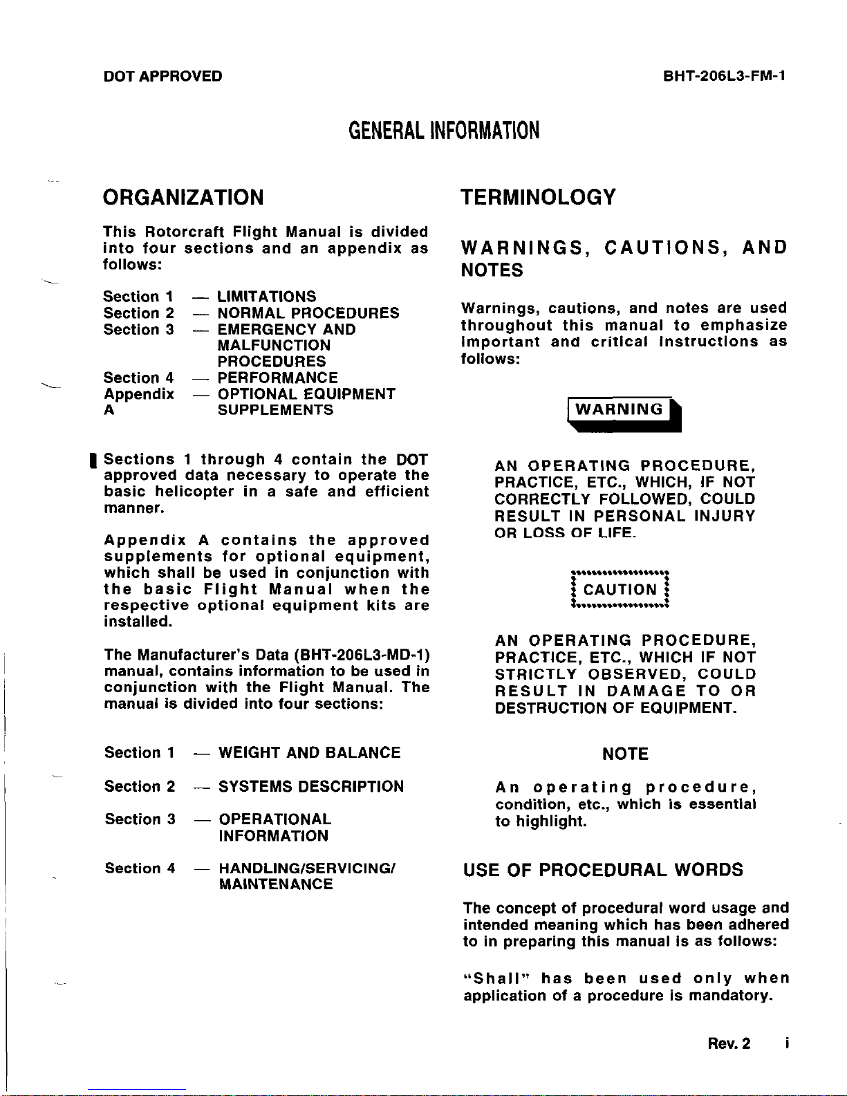
WARNINGS, CAUTIONS, AND
NOTES
Warnings, cautions, and notes are used
throughout this manual to emphasize
important and critical instructions as
follows:
AN OPERATING PROCEDURE,
PRACTICE, ETC., WHICH, IF NOT
CORRECTLY FOLLOWED, COULD
RESULT IN PERSONAL INJURY
OR LOSS OF LIFE.
AN OPERATING PROCEDURE,
PRACTICE, ETC., WHICH IF NOT
STRICTLY OBSERVED, COULD
RESULT IN DAMAGE TO OR
DESTRUCTION OF EQUIPMENT.
NOTE
An operating procedure,
condition, etc., which is essential
to highlight.
USE OF PROCEDURAL WORDS
The concept of procedural word usage and
intended meaning which has been adhered
to in preparing this manual is as follows:
“Shall” has been used only when
application of a procedure is mandatory.
Rev. 2 i
BHT-206L3-FM-1
“Should” has been used only when
application of a procedure is
recommended.
“May” and “need not” have been used only
when application of a procedure is
optional.
“Will” has been used only to indicate
futurity, never to indicate a mandatory
procedure.
ABBREVIATIONS AND ACRONYMS
Abbreviations and acronyms used
throughout this manual are defined as
follows:
AC
- Alternating Current
A/F
- Airframe
ANTI
COLL LT -
Anticollision Light
APU
BAT
C
CG
DC
DECR
ECS
ELT
ENG
F
ft
GEN
GOV
- Alternate Power Unit
- Battery
- Celsius
-
Center of Gravity
- Direct Current
- Decrease
- Environmental Control
System
- Emergency Locater
Transmitter
- Engine
- Fahrenheit
- Foot, Feet
- Generator
- Governor
Hd
-
Hg -
HP -
HYDR IDLE REL IFR IGE -
IN
-
INCR INST LT KCAS -
kg -
LBS KIAS KTAS LDG LTS LT MCP -
mm
-
MPH
OAT OGE POS LT -
PSI QTY RLY RPM
DOT APPROVED
Density Altitude
Mercury
Pressure Altitude
Hydraulic
Idle Release
Instrument Flight Rules
In Ground Effect
Inch(es)
Increase
Instrument Light
Knots Calibrated Airspeed
Kilograms
Pounds
Knots Indicated Airspeed
Knots True Airspeed
Landing Lights
Light
Maximum Continuous
Power
millimeter
Miles Per Hour (Statute)
Outside Air Temperature
Out of Ground Effect
Position Light
Pounds per Square Inch
Quantity
Relay
Revolutions Per Minute
ii
Rev. 2
FAA APPROVED
BHT-206L3-FM-1
SL - Sea Level
TOT or
- Turbine Outlet Temperature
TURB OUT
TEMP
T/R - Tail Rotor
TRANS - Transmission
VFR
- Visual Flight Rules
Vne - Never Exceed Velocity
WRN
- Warning
XMSN
- Transmission
FAA APPROVED
BHT-206L3-FM-1
Paragraph
TABLE OF CONTENTS
1-1
1-2
-
1-3
1-4
1-5
1-6
1-7
1-8
1-9
1-10
1-11
1-12
1-13
1-14
1-15
1-16
1-17
1-18
1-19
1-20
1-21
1-22
1-23
1-24
1-25
1-26
1-27
1-28
1-29
1-30
1-31
1-32
1-33
1-34
1-35
1-36
1-37
GENERAL
................................................................
BASIS OF CERTIFICATION
..............................................
TYPE OF OPERATION
...................................................
OPTIONAL EQUIPMENT..
...............................................
FLIGHT CREW
...........................................................
WElGHT/CG
..............................................................
WEIGHT
.............................................................
CENTER OF GRAVITY - LONGITUDINAL
.........................
CENTER OF GRAVITY - LATERAL
................................
DOOR(S) OFF
.......................................................
AIRSPEED
...............................................................
ALTITUDE
................................................................
AMBIENT AIR TEMPERATURE.. ........................................
MANEUVERING
..........................................................
ELECTRICAL
.............................................................
GENERATOR
........................................................
POWERPLANT
...........................................................
GAS PRODUCER RPM..
............................................
POWER TURBINE RPM ...............
. . . . . . . . . . . . . . . . . . . . . . . . . . . . . .
T OT) . . . . . . . . . . . . . . . . . . . . . . . . .
TURBINE OUTLET TEMPERATURE (
ENGINE TORQUE ....................
FUEL PRESSURE ....................
ENGINE OIL PRESSURE.. ...........
ENGINE OIL TEMPERATURE.. ......
..............................
..............................
..............................
..............................
..............................
ANTIICE ...............................
STARTER
............................................................
TRANSMISSION
..........................................................
TRANSMISSION OIL PRESSURE..
.................................
TRANSMISSION OIL TEMPERATURE
..............................
ROTOR
...................................................................
ROTOR RPM - POWER ON..
......................................
ROTOR RPM - POWER OFF
.......................................
FUEL AND OIL.. .........................................................
FUEL
................................................................
ENGINE OIL.. .......................................................
TRANSMISSION AND TAIL ROTOR GEARBOX OIL
...............
HYDRAULIC
..............................................................
Page
Number
1-3
1-3
1-3
1-3
1-3
1-3
1-3
1-4
1-4
1-4
1-4
1-4
1-4
1-4
1-8
1-8
1-8
1-8
1-8
1-8
1-9
1-9
1-9
1-9
1-10
1-10
1-10
1-10
1-10
1-10
1-10
1-10
1-10
1-10
1-11
1-11
1-11
l-1
BHT-206L3-FM-1 FAA APPROVED
Figure
Number
LIST OF FIGURES
Title
Page
Number
1-1
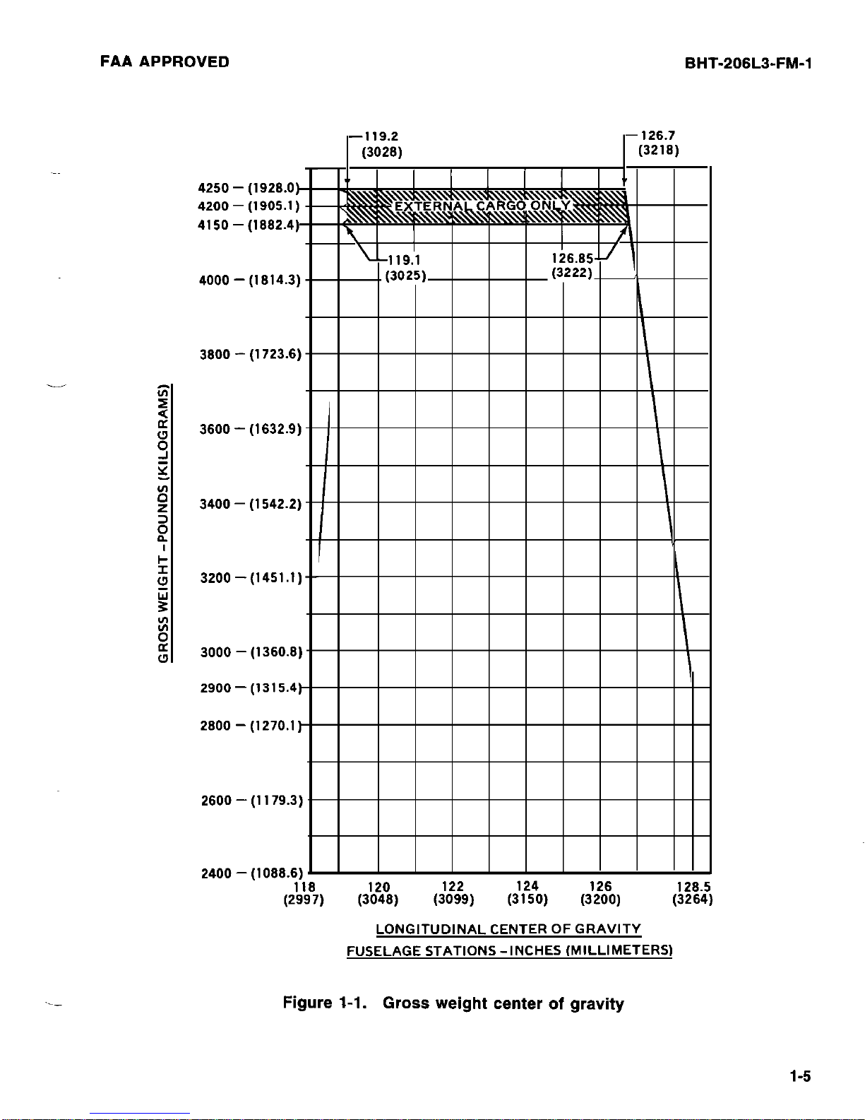
Gross weight center of gravity . . . . . . . . . . . . . . . . . . . . . . . . . . . . . . . . . . . . . . . . . . .
1-5
1-2
Placards and decals....................................................... 1-6
1-3
Instrument markings . . . . . . . . . . . . . . . . . . . . . . . . . . . . . . . . . . . . . . . . . . . . . . . . . . . . . .
1-12
1-2
TC
APPROVED
BHT-206L3-FM-1
Section
1
.
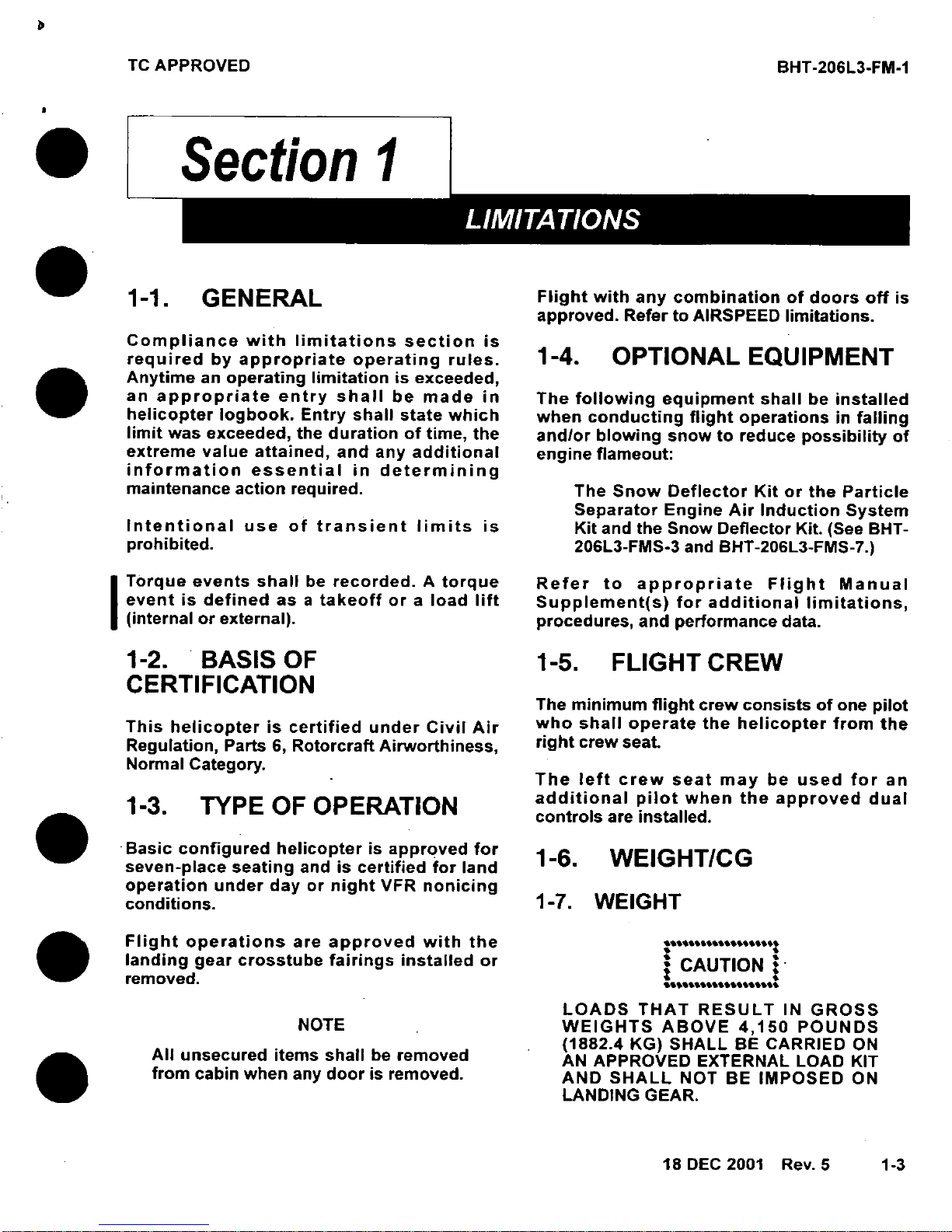
1-1.
GENERAL
Flight
with
any
combination
of
doors
off
is
approved.
Refer
to
AIRSPEED
limitations.
Compliance
with
limitations
section
is
required
by
appropriate
operating
rules.
1-4.
OPTIONAL
EQUIPMENT
Anytime
an
operating
limitation
is
exceeded,
an
appropriate
entry
shall
be
made
in
The
following
equipment
shall
be
installed
helicopter
logbook.
Entry
shall
state
which
when
conducting
flight
operations
in
falling
limit
was
exceeded,
the
duration
of
time,
the
and/or
blowing
snow
to
reduce
possibility
of
extreme
value
attained,
and
any
additional
engine
flameout:
information
essential
in
determining
maintenance
action
required.
The
Snow
Deflector
Kit
or
the
Particle
Separator
Engine
Air
Induction
System
Intentional
use
of
transient
limits
is
Kit
and
the
Snow
Deflector
Kit.
(See
BHT-
prohibited.
206L3-FMS-3
and
BHT-206L3-FMS-7.)
Torque
events
shall
be
recorded.
A
torque
Refer
to
appropriate
Flight
Manual
event is
defined
as
a
takeoff
or a load
lift
Supplement(s)
for
additional
limitations,
(internal
or
external),
procedures,
and
performance
data.
1-2.
BASIS
OF
1-5.
FLIGHT
CREW
CERTIFICATION
The
minimum
flight
crew
consists of
one
pilot
This
helicopter
is
certified
under
Civil Air
who
shall
operate
the
helicopter
from
the
Regulation,
Parts
6,
Rotorcraft
Airworthiness,
right
crew
seat
Normal
Category.
The
left
crew
seat
may
be
used
for
an
1-3.
TYPE
OF
OPERATION
additional
pilot
when
the approved
dual
controls
are
installed.
seven-place
seating
and
is
certified
for
land
*
H
operation
under
day
or
night
VFR
nonicing
conditions.
1-7. WEIGHT
Flight
operations
are
approved
with
the
..
....
landing
gear
crosstube
fairings
installed
or
CAUTION
removed.
LOADS
THAT
RESULT
IN
GROSS
NOTE
WEIGHTS
ABOVE
4,150
POUNDS
(1882.4
KG)
SHALL
BE
CARRIED
ON
All
unsecured
items
shall
be
removed
AN
APPROVED
EXTERNAL
LOAD
KIT
from
cabin
when
any
door
is
removed.
AND
SHALL
NOT
BE
IMPOSED
ON
LANDING
GEAR.
18
DEC
2001
Rev.
5
1-3
BHT-206L3-FM-1
DOTAPPROVED
Maximum internal approved gross weight
for takeoff and landing is 4,150 pounds
(1882.4 kilograms).
Minimum combined crew weight at
fuselage station 65.0 is 170 pounds (77.1
kilograms) when operating in accordance
with the SELECTIVE PASSENGER
LOADING placard.
1-8. CENTER OF GRAVITY LONGITUDINAL
For gross weight longitudinal center of
gravity limits, refer to figure l-l.
The standard helicopter [standard seating
and fuel system) is ballasted in
accordance with the Weight Empty Center
of Gravity chart in the maintenance
manual. The SELECTIVE PASSENGER
LOADING placard shall be installed and
may be used for loading passengers only
within appropriate weight limitations
without computing center of gravity. When
passengers are seated other than in
accordance with the selective loading
placard or the baggage compartment is
utilized, the pilot is responsible for
determining weight and balance to ensure
gross weight and center of gravity will
remain within limits throughout each flight.
The helicopter with nonstandard fuel
system or seating arrangement is not
ballasted in accordance with the Weight
Empty Center of Gravity chart in the
maintenance manual. Selective passenger
loading does not apply and the
ALTERNATE placard shall be installed. The
pilot is responsible for determining weight
and balance to ensure gross weight and
center of gravity will remain within limits
throughout each flight.
Refer to BHT-206L3-MD-1 for loading
tables and instructions.
1-9. CENTER OF GRAVITY -
LATERAL
Lateral center of gravity limits are 4.0
inches (102 mm) left of and 3.5 inches (89
mm) right of fuselage centerline.
1-4 Rev. 4
1-10. DOOR(S) OFF
Determine weight change after doors have
been removed and adjust ballast if
necessary. Refer to BHT-206L3-MD-1.
1-11. AIRSPEED
Basic V,, is 130 KIAS (150 MPH) sea level
to 3,000 feet density altitude. Decrease V,,
for ambient conditions in accordance with
AIRSPEED LIMITATIONS placard (figure 1-
2).
V ne is 84 KIAS (96 MPH) at 85 to 100%
TORQUE takeoff power.
Vne, is 90 KIAS (104 MPH) with any door(s)
off, not to exceed placarded Vne.
1-12. ALTITUDE
Maximum operating pressure altitude is
20,000 feet.
NOTE
For high altitude pressure
operation, refer to appropriate
rules for oxygen requirements.
1-13.
AMBIENT AIR
TEMPERATURE
The maximum sea level ambient air
temperature for operation is +51.7°C
(+125°F) and decreases with pressure
altitude at the standard lapse rate of 2°C
(3.6°F)/1000 feet to 20,000 feet.
1-14. MANEUVERING
Aerobatic maneuvers are prohibited.
FAA APPROVED
BHT-206L3-FM-1
-119.2
(3026)
Figure 1-1. Gross weight center of gravity
1-5
BHT-206L3-FM-1
TC
APPROVED
|IU~~~
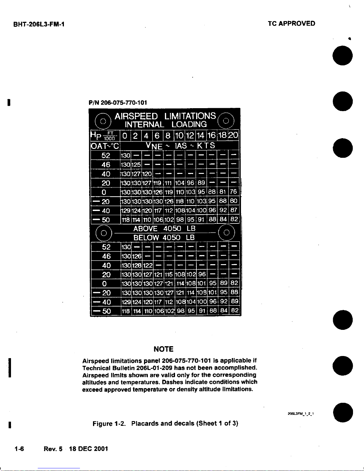
P/N
206-075-770-101
i" e
*0
S
a
Z
s
NOTE
Airspeed
limitations
panel
206-075-770-101
Is
applicable
if
Technical
Bulletin
206L-01-209
has
not
been
accomplished.
Airspeed
limits
shown
are
valid only
for
the
corresponding
altitudes
and
temperatures.
Dashes
indicate
conditions
which
exceed
approved
temperature
or
density
altitude
limitations.
206L3FM_121
Figure
1-2.
Placards
and
decals
(Sheet I of
3)
4
1-6
Rev. 5 18
DEC
2001
TC
APPROVED
BHT-206L3-FM-1
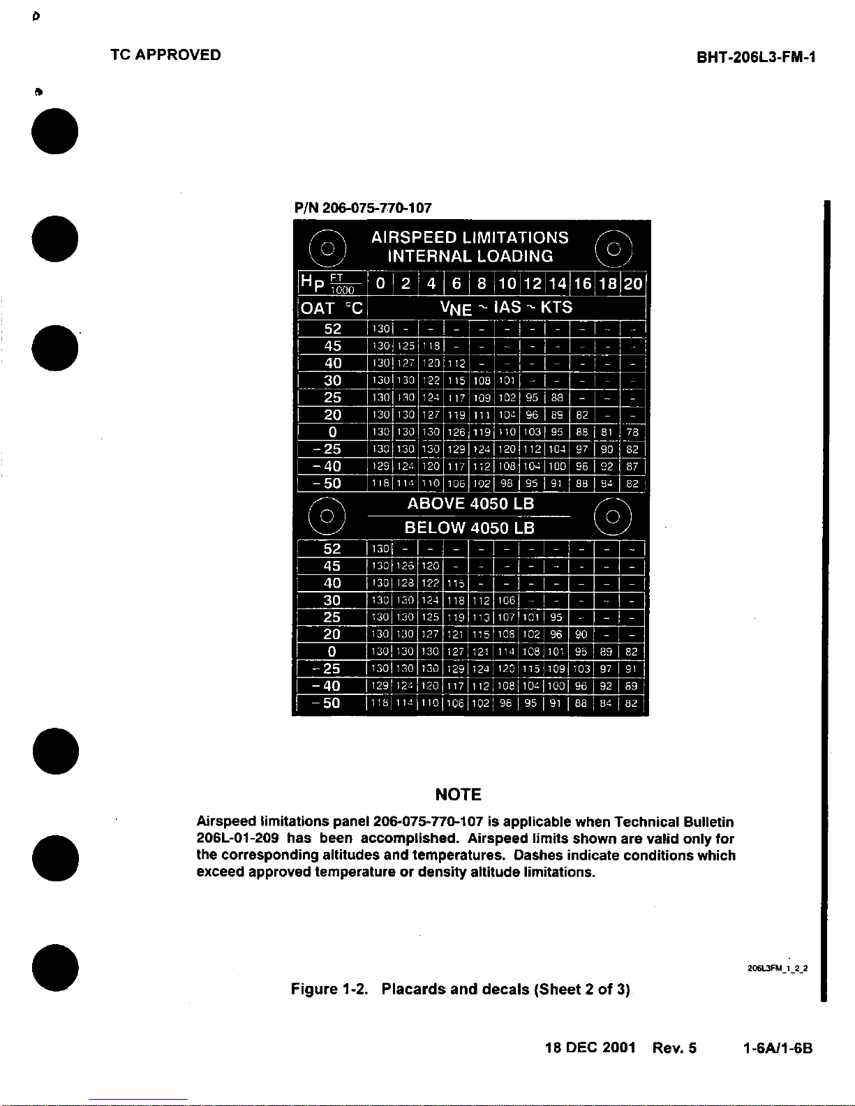
P/N
206-075-770-107
NOTE
Airspeed
limitations
panel
206-075-770-107
is
applicable
when
Technical
Bulletin
206L-01-209
has
been
accomplished.
Airspeed
limits
shown
are
valid
only for
the
corresponding
altitudes
and
temperatures.
Dashes
indicate
conditions
which
exceed approved temperature
or
density
altitude
limitations.
Figure
1-2.
Placards
and
decals
(Sheet 2 of
3)
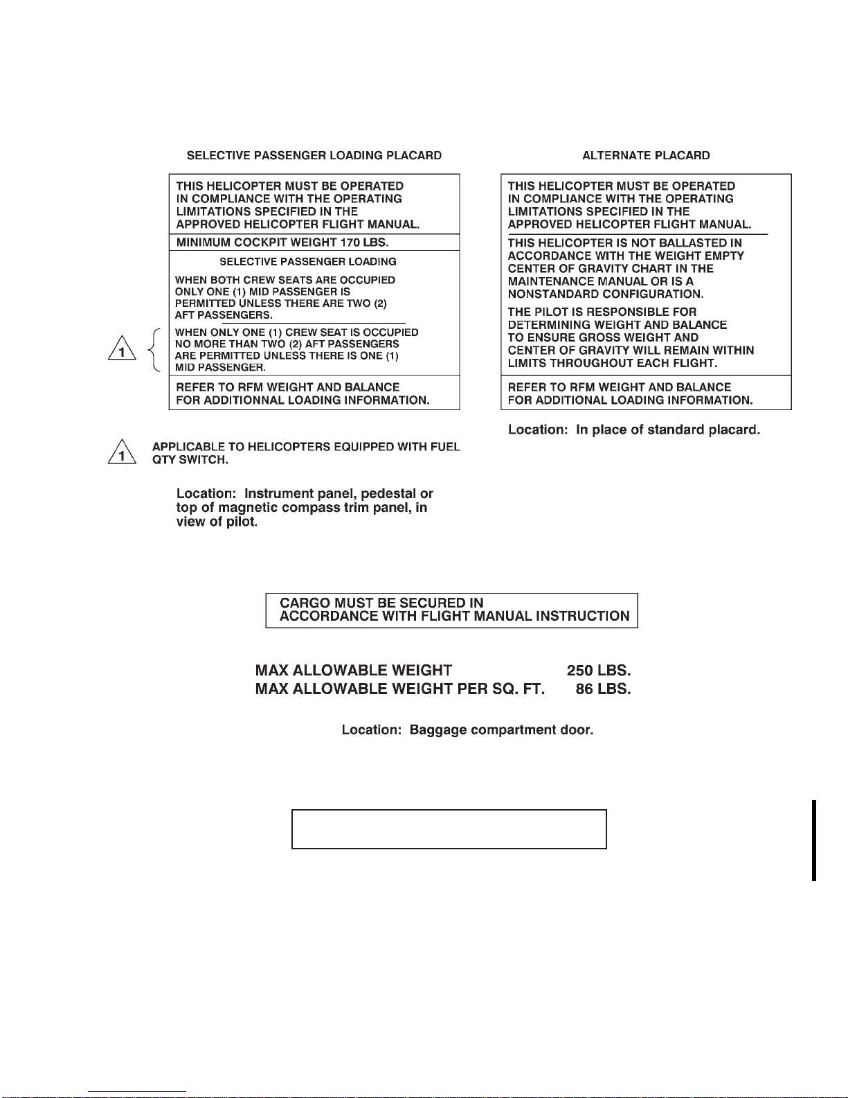
TC APPROVED BHT-206L3-FM-1
Figure 1-2. Placards and Decals (Sheet 3 of 3)
AVOID CONT OPS 71.8% TO 91.5% N2
Location: Instrument panel.
206L3FM_1_0001
26 APR 2005 Rev. 6 1-7

BHT-206L3-FM-1 TC APPROVED
1-15. ELECTRICAL
1-16. GENERATOR
Continuous
operation
Maximum 90% DC LOAD
0 to 90% DC
LOAD
1-17. POWERPLANT
Allison model 250-C30P.
1-18. GAS PRODUCER RPM
Continuous
operation
Maximum 105%
Maximum transient
(Do not exceed 10
seconds above
105%)
63 to 105%
106%
Maximum continuous 100%
Transient overspeed
range
NOTE
Refer to Allison Operation and
Maintenance Manual for transient
overspeed limits.
100 to 103%
1-20. TURBINE OUTLET
TEMPERATURE (TOT)
WARNING
EXCEEDING 768°C TURB OUT TEMP
OR 100% TORQUE CAN CAUSE GAS
PRODUCER TOPPING WITH
RESULTANT ROTOR RPM DROOP.
Continuous
operation
100 to 716°C
1-19. POWER TURBINE RPM
WARNING
USE OF THE THROTTLE TO CONTROL
RPM IS NOT AUTHORIZED.
(REFER TO SECTION 3, EMERGENCY
PROCEDURES — ENGINE
OVERSPEED FOR EXCEPTION.)
Avoid continuous
operations
Minimum 97%
Continuous
operation
71.8 to 91.5%
97 to 100%
Maximum continuous 716°C
5 minute takeoff
range
Maximum for takeoff 768°C
Maximum transient
(Do not exceed 10
seconds above
768°C).
Maximum for starting
and shutdown (Do
not exceed 10
seconds above
768°C.)
716 to 768°C
871°C
927°C
1-8 Rev. 6 26 APR 2005
--
-
DOTAPPROVED
NOTE
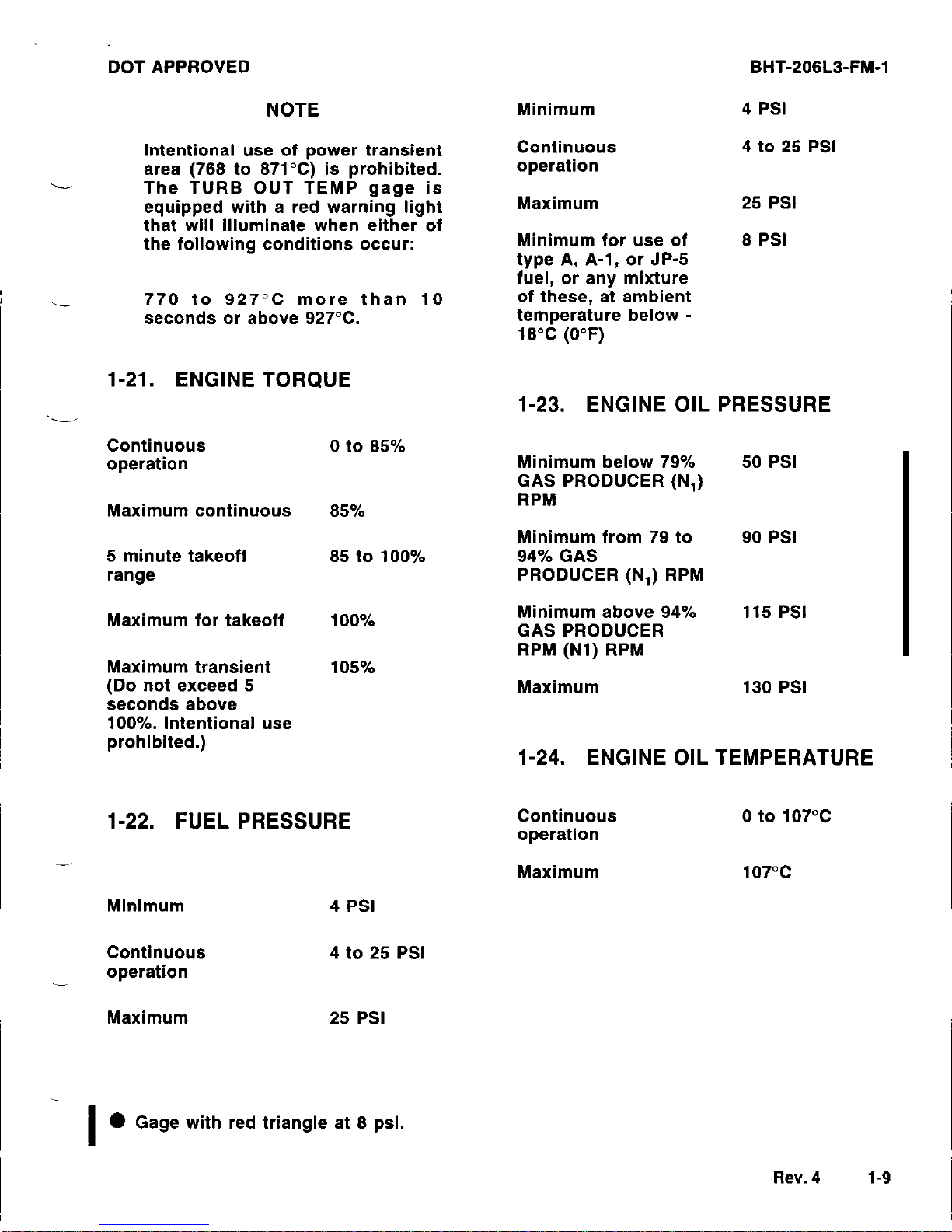
Intentional use of power transient
area (768 to 871°C) is prohibited.
The TURB OUT TEMP gage is
equipped with a red warning light
that will illuminate when either of
the following conditions occur:
770 to 927°C more than 10
seconds or above 927°C.
1-21. ENGINE TORQUE
Continuous
operation
0 to 85%
Maximum continuous
85%
5 minute takeoff
range
85 to 100%
Maximum for takeoff
Maximum transient
(Do not exceed 5
seconds above
100%. Intentional use
prohibited.)
100%
105%
1-22. FUEL PRESSURE
Minimum
Continuous
operation
4 PSI
4 to 25 PSI
Maximum
25 PSI
BHT-206L3-FM-1
Minimum
Continuous
operation
4 PSI
4 to 25 PSI
Maximum
Minimum for use of
type A, A-l, or JP-5
fuel, or any mixture
of these, at ambient
temperature below 18°C (0°F)
25 PSI
8 PSI
1-23. ENGINE OIL PRESSURE
Minimum below 79%
50 PSI
GAS PRODUCER (N,)
RPM
Minimum from 79 to
90 PSI
94% GAS
PRODUCER (N,) RPM
Minimum above 94%
115 PSI
GAS PRODUCER
RPM (N1) RPM
Maximum
130 PSI
1-24. ENGINE OIL TEMPERATURE
Continuous
operation
0 to 107°C
Maximum
107°C
I
l
Gage with red triangle at 8 psi.
Rev. 4
1-9
BHT-206L3-FM-1
DOT APPROVED
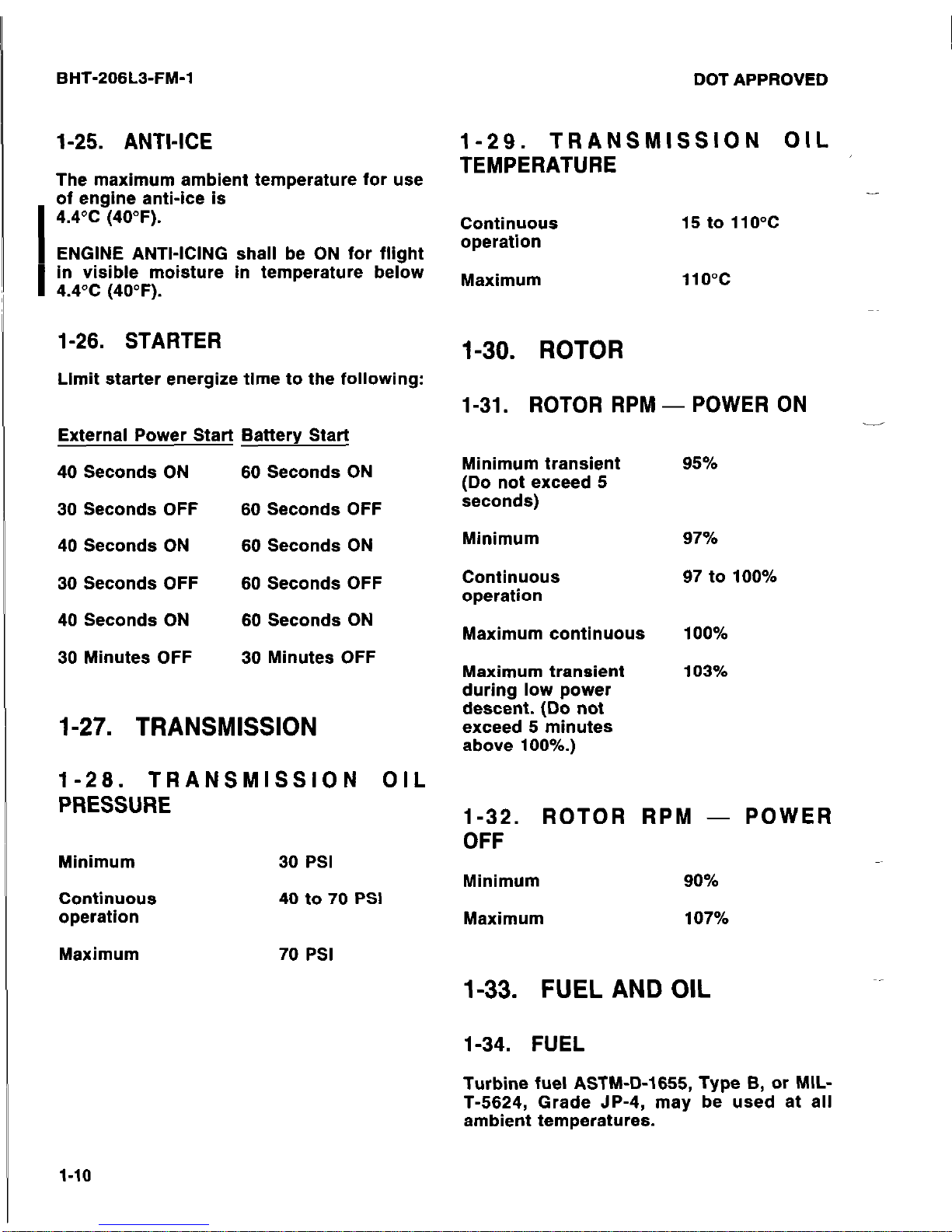
1-25. ANTI-ICE
The maximum ambient temperature for use
I
of engine anti-ice is
4.4°C (40°F).
ENGINE ANTI-ICING shall be ON for flight
I
in visible moisture in temperature below
4.4°C (40°F).
1-26. STARTER
Limit starter energize time to the following:
External Power Start Battery Start
40 Seconds ON
60
Seconds ON
30 Seconds OFF
60
Seconds OFF
40 Seconds ON
60
Seconds ON
30 Seconds OFF
60
Seconds OFF
40 Seconds ON
60
Seconds ON
30 Minutes OFF
30
Minutes OFF
1-27. TRANSMISSION
1-26.
TRANSMISSION OIL
PRESSURE
Minimum
Continuous
operation
Maximum
30 PSI
40 to 70 PSI
70 PSI
1-29. TRANSMISSION OIL
TEMPERATURE
Continuous
operation
15 to 110°C
Maximum
110°C
1-30. ROTOR
1-31. ROTOR RPM - POWER ON
Minimum transient
(Do not exceed 5
seconds)
-
95%
Minimum
Continuous
operation
Maximum continuous
Maximum transient
during low power
descent. (Do not
exceed 6 minutes
above 100%.)
97%
97 to 100%
100%
103%
1-32. ROTOR RPM - POWER
OFF
Minimum
90%
Maximum
107%
1-33. FUEL AND OIL
1-34. FUEL
Turbine fuel ASTM-D-1655, Type B, or MIL-
T-5624, Grade JP-4, may be used at all
ambient temperatures.
1-10
DOT APPROVED BHT-206L3-FM-1
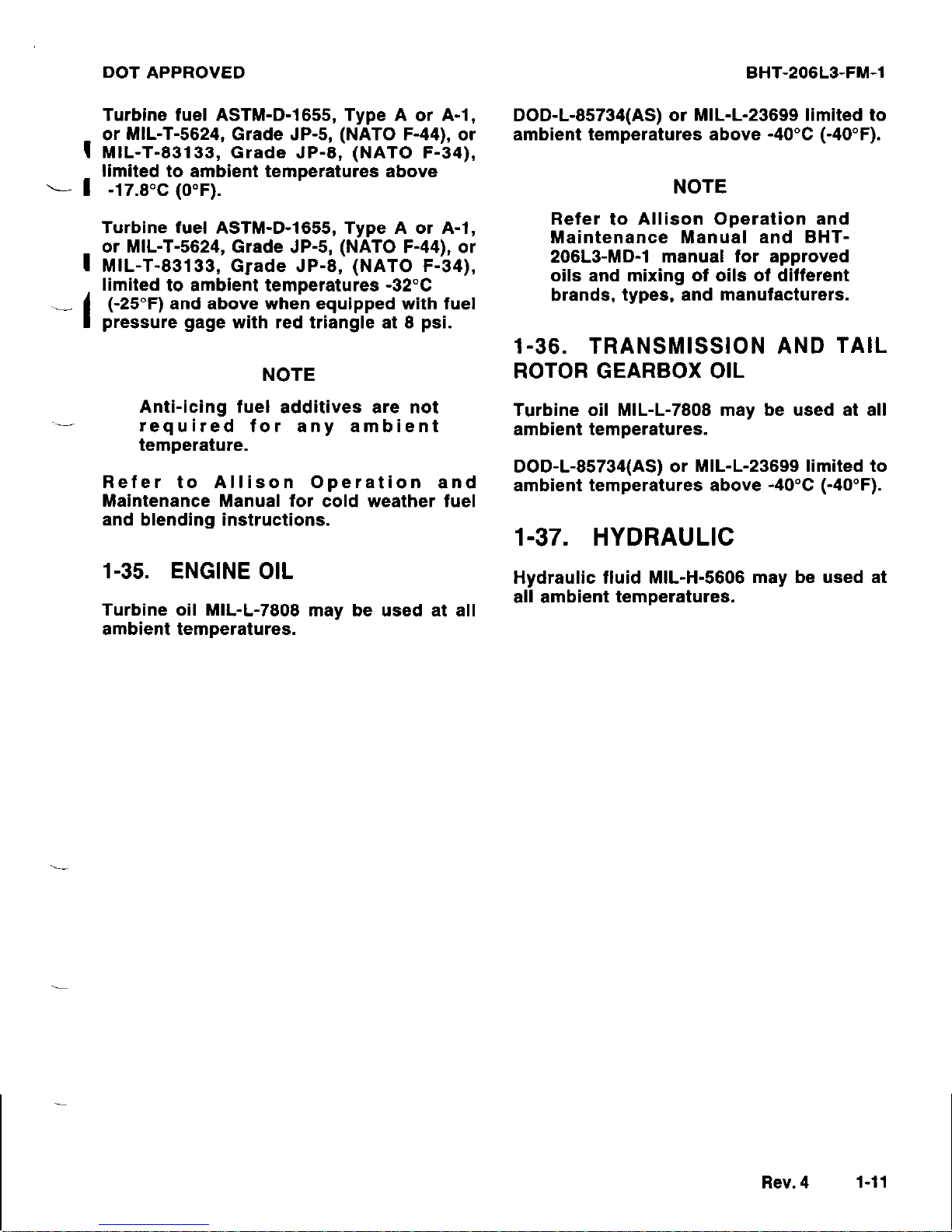
Turbine fuel ASTM-D-1655, Type A or A-l,
or MIL-T-5624, Grade JP-5, (NATO F-44), or
MIL-T-83133, Grade JP-8, (NATO F-34),
limited to ambient temperatures above .
- -17.8% (0°F).
Turbine fuel ASTM-D-1655, Type A or A-l,
or MIL-T-5624, Grade JP-5, (NATO F-44), or
MIL-T-83133, Grade JP-8, (NATO F-34),
limited to ambient temperatures -32°C
(-25°F) and above when equipped with fuel
pressure gage with red triangle at 6 psi.
NOTE
Anti-icing fuel additives are not
required for any ambient
temperature.
fer to Allison Operation and
intenance Manual for cold weather fuel
and blending instructions.
Re
Ma
1-35. ENGINE OIL
Turbine oil MIL-L-7808 may be used at all
ambient temperatures.
DOD-L-85734(AS) or MIL-L-23699 limited to
ambient temperatures above -40°C (-40°F).
NOTE
Refer to Allison Operation and
Maintenance Manual and BHT206L3-MD-1 manual for approved
oils and mixing of oils of different
brands, types, and manufacturers.
1-36. TRANSMISSION AND TAIL
ROTOR GEARBOX OIL
Turbine oil MIL-L-7808 may be used at all
ambient temperatures.
DOD-L-85734(AS) or MIL-L-23699 limited to
ambient temperatures above -40°C (-40°F).
1-37. HYDRAULIC
Hydraulic fluid MIL-H-5606 may be used at
all ambient temperatures.
Rev. 4
1-11
BHT-206L3-FM-1
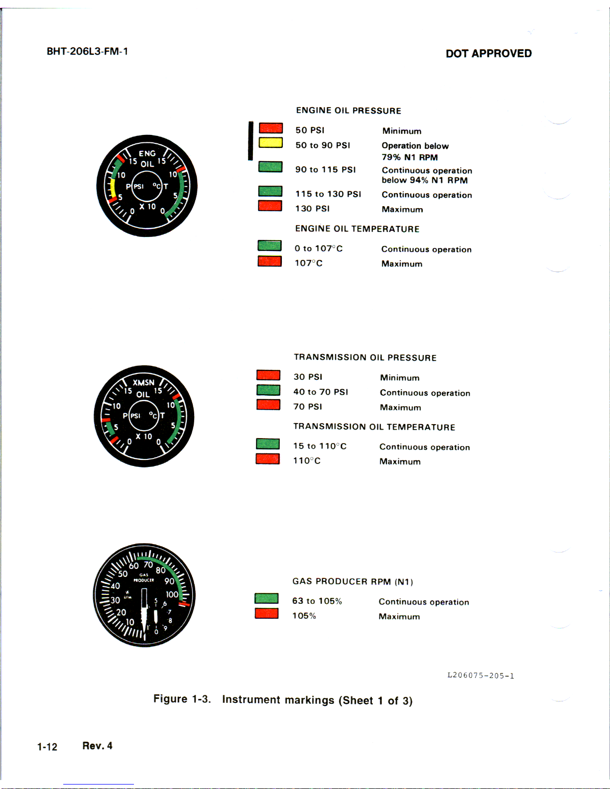
DOT APPROVED
ENGINE OIL PRESSURE
50 PSI
Mhmum
50 to so PSI
Operation below
79% Nl RPM
so to 115 PSI
Continuous operatmn
below 94% Nl RPM
115 to 130 PSI
Contmuous operation
130 PSI
Maximum
ENGINE OIL TEMPERATURE
m 0 to 107oc
Continuous operation
Maximum
TRANSMISSION OIL PRESSURE
30 PSI
Mmlmum
40 to 70 PSI
Continuous operatlo”
70 PSI
Maximum
TRANSMISSION OIL TEMPERATURE
15 to 110°C
Continuous operatmn
110°C
Maxmum
GAS PRODUCER RPM (Nl,
Continuous operation
Maximum
L206075-205-l
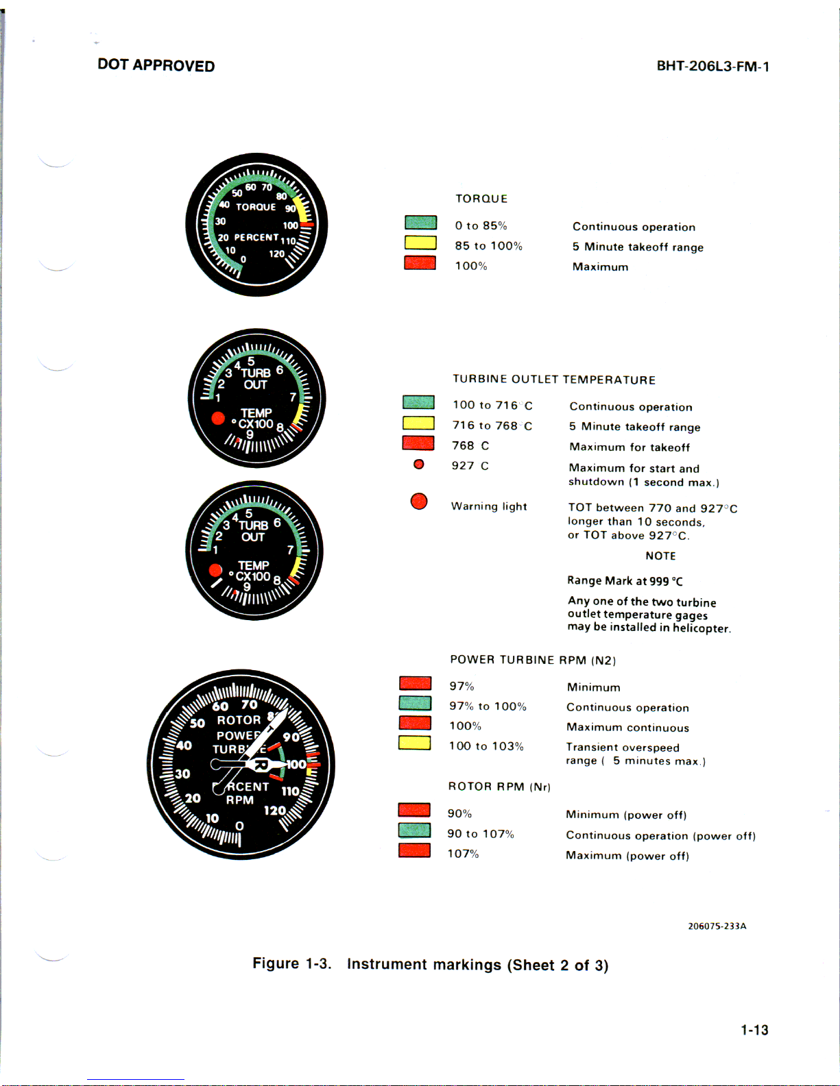
Figure 1-3. instrument markings (Sheet 1 of 3)
1-12
Rev. 4
.
DOT APPROVED
BHT-206L3-FM-1
TORQUE
0 to 85%
85 to 100%
100%
TURBINE OUTLET
m
100 to716 C
r”
716fo768 C
768 C
@
927 C
a
Warn1nq lqht
Continuous operatmn
5 Mmute takeoff range
Maximum
TEMPERATURE
Continuous operatmn
5 Minute takeoff range
Manmum for takeoff
MaxImum for start and
shutdown (1 second max )
TOT between 770 and 927 C
longer than 10 seconds.
or TOT above 927 C
NOTE
Range Mark at 999 “C
Any one of the two turbme
outlet temperature gages
may be mstalled I” hellcopter
POWER TURBINE RPM (N2)
97%
97% to 100%
100%
100 to 103%
Minimum
Continuous operation
Maximum continuous
Transient overspeed
range f 5 minutes rmx.)
Mnmum (power off)
Continuous operat,on (power off)
Mawmum (power off)
Fiaure 1-3.
Instrument markings (Sheet 2 of 3)
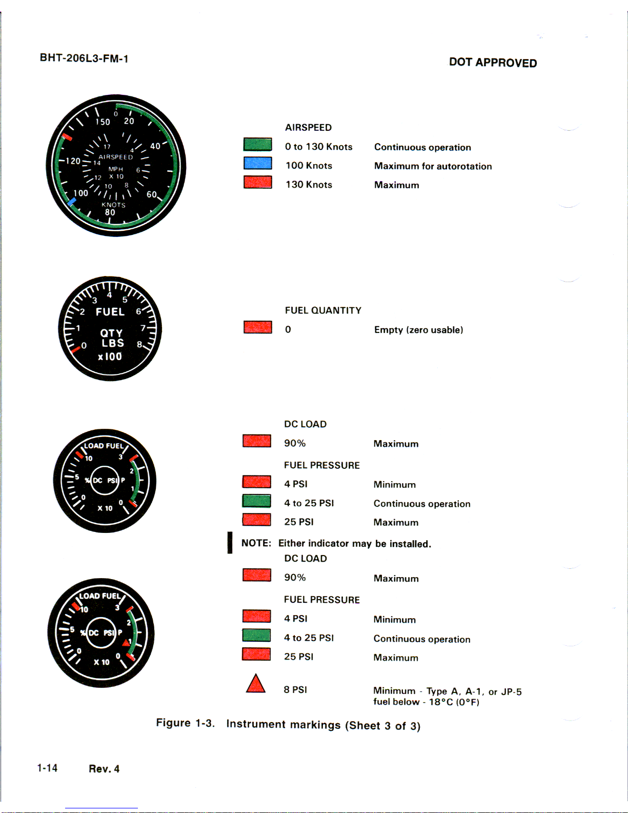
BHT-206L3-FM-1
DOT APPROVED
AIRSPEED
:o 130 Knots
IO Knots
130 Knots
Continuous operation
Maximum for autorotation
Maximum
FUEL QUANTITY
0
Empty (zero usable)
“L LUAU
I 90%
Maximum
FUEL PRESSURE
4 PSI
Minimum
4 to 25 PSI
Continuous operatio
I 25 PSI
Maximum
I
NOTE: Either indicator may
be
installed.
m
DC LOAD
n
Maximum
FUEL PRESSURE
m 4PSI
Minimum
0 25 PSI
Continuous operation
PSI Maximum
A
8 PSI Minimum Type A, A-l, or JP-5
fuel below 18°C (O°Fj
Figure 1-3.
Instrument markings (Sheet 3 of 3)
1-14 Rev.
4

FAA APPROVED
BHT-206L3-FM-1
Paragraph
TABLE OF CONTENTS
2-1
2-2
2-3
2-4
2-6
2-6
2-7
2-6
2-9
2-10
2-11
2-12
2-13
2-14
2-15
2-16
2-17
2-l 6
2-19
2-20
2-21
2-22
2-23
2-24
2-25
2-26
INTRODUCTION ..........................................................
OPERATING LIMITATIONS ..............................................
FLIGHT PLANNING ......................................................
TAKEOFF AND LANDING DATA
....................................
WEIGHT AND BALANCE
............................................
PREFLIGHT CHECK .....................................................
BEFORE EXTERIOR CHECK
............................................
EXTERIOR CHECK..
.....................................................
FUSELAGE - CABIN RIGHT SIDE..
...............................
FUSELAGE - CENTER RIGHT SIDE..
.............................
FUSELAGE - AFT RIGHT SIDE
....................................
FUSELAGE - FULL AFT..
.........................................
FUSELAGE - AFT LEFT SIDE
.....................................
FUSELAGE - CABIN LEFT SIDE
..................................
FUSELAGE - FRONT ..............................................
INTERIOR AND PRESTART CHECK.. ...................................
ENGINE STARTING.. ....................................................
PRELIMINARY HYDRAULIC SYSTEMS CHECK..
.......................
ENGINE RUNUP .........................................................
HYDRAULIC SYSTEMS CHECK
....................................
BEFORE TAKEOFF ......................................................
TAKEOFF ................................................................
INFLIGHT OPERATIONS.. ...............................................
DESCENT AND LANDING ...............................................
ENGINE SHUTDOWN ....................................................
AFTER EXITING HELICOPTER
..........................................
LIST OF FIGURES
Figure
Number Title
Page
Number
2-3
2-3
2-3
2-3
2-3
2-3
2-5
2-5
2-5
2-5
2-6
2-6
2-7
2-8
2-8
2-9
2-10
2-11
2-11
2-l 1
2-11
2-12
2-12
2-12
2-13
2-13
Page
Number
2-l
Preflight check sequence . . . . . . . . . . . . . . . . . . . . . . . . . . . . . . . . . . . . . . . . . . . . . . . . . 2-4
2-112-2
FAA APPROVED
BHT-206L3-FM-1
2-1. INTRODUCTION
This section contains instructions and
procedures for operating the helicopter
from the planning stage, through actual
flight conditions, to securing the
helicopter after landing.
Normal and standard conditions are
assumed in these procedures. Pertinent
data in other sections is referenced when
applicable.
The instructions and procedures contained
herein are written for the purpose of
standardization and are not applicable to
all situations.
2-2. OPERATING
LIMITATIONS
The minimum and maximum limits, and the
normal and cautionary operating ranges
for the helicopter and its subsystems are
indicated by instrument markings and
placards. The instrument markings and
placards represent careful aerodynamic
calculations that are substantiated by
flight test data. Refer to Section 1,
--
LIMITATIONS, for a detailed explanation of
each operating limitation.
2-3. FLIGHT PLANNING
Each flight should be planned adequately
to ensure safe operations and to provide
the pilot with the data to be used during
flight.
Check type of mission to be performed
and destination.
Select appropriate performance charts to
be used from Section 4, PERFORMANCE.
2-4. TAKEOFF AND LANDING
DATA
Refer to Section 1 for takeoff and landing
weight limits and to Section 4 for
performance information.
2-5. WEIGHT AND BALANCE
Determine proper weight and balance of
the helicopter as follows:
1.
Consult BHT-206L3-MD-1 for
instructions.
2. Compute takeoff and anticipated
landing gross weight, check
helicopter center of gravity (CG)
locations, and determine weight of
fuel, oil, payload, etc.
3. Ensure weight/CG limits listed in
Section 1 have not been exceeded.
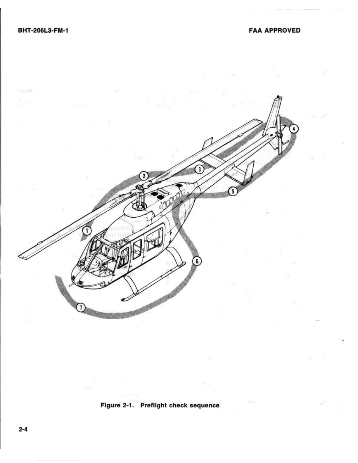
2-6. PREFLIGHT CHECK
The pilot is responsible for determining
whether the helicopter is in condition for
safe flight. Refer to figure 2-l for preflight
check sequence.
NOTE
The preflight check is not
intended to be a detailed
mechanical inspection, but simply
a guide to help the pilot check the
condition of the helicopter. It may
be as comprehensive as
conditions warrant at the
discretion of the pilot.
Rev. 1
2-31
BHT-206L3-FM-1
FAAAPPROVED
Figure 2-1. Preflight check sequence
2-4
DOT APPROVED
BHT-206L3-FM-1
All areas checked shall include a
visual check for evidence of
corrosion, particularly when
helicopter is flown near or over
salt water or in areas of high
industrial emissions.
3.
Hydraulic system filters Bypass indicator retracted.
4.
Hydraulic actuators and lines Condition, security, interference,
leakage.
2-7. BEFORE EXTERIOR
CHECK
5.
6.
Forward fairing - Secured.
--
1. Flight planning - Completed.
2. Publications - Checked.
3.
Gross weight and CG Computed.
4.
Helicopter servicing -
Completed.
5. Battery - Connected.
Transmission
- Check oil level.
Verify actual presence of oil in
sight gage.
7. Transmission oil cooler lines Condition and security.
6.
Nodal beam - Check condition
and security of elastomeric
bearings, elastomeric straps, and
fore and aft restraint damper.
9.
2-8. EXTERIOR CHECK
2-9. FUSELAGE
- CABIN RIGHT
Main driveshaft forward coupling
- Condition, security, and grease
leakage. Check Temp-Plates (four
places) for evidence of elevated
temperature indicated by dot
changing color to black.
SIDE
1.
2.
3.
4.
5.
2-10.
Right static port - Condition.
Cabin doors - Condition and
security.
Windows
- Condition and
security.
Landing gear - Condition and
ground handling wheel removed.
Forward and aft crosstube
fairings - Secured, condition,
and aligned.
FUSELAGE
- CENTER
RIGHT SIDE
1. Engine inlet - Condition; remove
inlet covers.
2. Cabin roof, transmission cowling,
and engine air inlet area Cleaned of all debris and
accumulated snow and ice;
cowling secured.
IF ANY TEMP-PLATE IS MISSING
OR HAS BLACK DOTS
MAINTENANCE PERSONNEL
SHALL ASSIST IN DETERMINING
AIRWORTHINESS.
10. Access door - Secured.
11. Rotor head - Condition.
12. Fuel filler cap - Visually check
fuel level and cap secured.
13. Fuel sump - Drain fuel sample
as follows:
a. FUEL BOOST circuit breakers
- out.
b. BAT switch - On.
c. FUEL VALVE switch - OFF.
d. PUSH FOR FUEL SUMP DRAIN
button -
Press, drain sample,
then release.
Rev. 3 2-5
BHT-206L3-FM-1
DOTAPPROVED
NOTE
Forward fuel cells can be drained
manually as desired.
14. A/F fuel filter - Drain and check
before first flight of the day as
follows:
a. FUEL VALVE switch - ON.
b. FUEL BOOST circuit breakers
- In.
c. Fuel filter drain valve - Open,
drain sample, then close.
NOTE
Filter test button is located on top
of fuel filter.
15. Fuel filter test button - Press
and check FUEL FILTER caution
light illuminated. Release switch
and check light extinguished.
16. FUEL VALVE switch - OFF.
17. BAT switch - OFF.
16. Powerplant Area
a. Main driveshaft aft coupling -
Condition, security, and grease
leakage. Check Temp-Plates
(four places) for evidence of
elevated temperature indicated
by dot changing color to black.
IF ANY TEMP-PLATE IS MISSING
OR HAS BLACK DOTS,
MAINTENANCE PERSONNEL
SHALL ASSIST IN DETERMINING
AIRWORTHINESS.
b. Engine - Condition; security
of attachments. Evidence of oil
leakage.
c. Engine mounts - Condition
and security.
d. Throttle linkage - Condition,
security,
and freedom of
operation.
e. Fuel control and mechanical
fuel pump - Security and
condition; evidence of leakage,
governor air lines.
f. Hoses and tubing - Chafing,
security, and condition.
19. Engine cowl - Secured.
20. Generator cooling scoop Clear of debris.
21.
Oil tank - Oil level, leaks,
security, and cap secured.
22. Access door - Secured.
23. Aft fairing - Secured.
2-11. FUSELAGE - AFT RIGHT
SIDE
1. Fuselage - Condition.
2. Tail. rotor driveshaft cover -
Condition and security.
3. Tailboom - Condition.
4. Horizontal stabilizer and position
light - Condition and security.
5. Sync elevator - Check lateral
freedom, bearing play, and clear
of obstructions.
6. Main rotor blade - Condition.
2-12. FUSELAGE - FULL AFT
1. Vertical fin - Condition.
2. Tail rotor guard - Condition and
security.
3. Anticollision light - Condition
and security of lens.
4. Aft position light - Condition.
5. Tail rotor gearbox - Oil level,
leaks and security.
2-6
Rev. 3
DOT APPROVED
6. Tail rotor - Tiedown removed,
condition and free movement.
7. Tail rotor controls - Condition and
security.
6. Tail rotor blades - Condition; tip
block security, evidence of
corrosion, and seal condition.
2-13. FUSELAGE - AFT LEFT
SIDE
FAILURE TO REMOVE ROTOR
TIEDOWNS BEFORE ENGINE
STARTING MAY RESULT IN
SEVERE DAMAGE AND POSSIBLE
INJURY.
1.
Main rotor blade - Tiedown
removed; condition.
2. Tailboom - Condition.
3. Tail rotor driveshaft cover Condition and security.
4. Horizontal stabilizer and position
light - Condition and security.
6. Sync elevator - Check lateral
freedom, bearing play, and clear of
obstructions.
6. Fuselage - Condition.
7.
Forward tail rotor driveshaft
coupling - Condition of splined
adapter.
6. Oil cooler blower shaft hanger
bearings - Evidence of grease
leakage and overheating.
9. Oil cooler blower - Clear of
obstruction and condition.
10. Oil cooler - Condition and leaks.
BHT-206L3-FM-1
11. Oil cooler access door - Secured.
12. Aft fairing - Secured.
13. Baggage compartment - Cargo
tied down, door secured.
14. Exhaust cover - Removed.
15. Powerplant Area
a. Engine - Condition; security of
attachments.
b. Engine mounts - Condition and
security.
c. Exhaust stack - Condition and
security.
d. Evidence of fuel and oil leaks.
e. Hoses and tubing for chafing
and condition.
f. Pneumatic lines - Condition and
security.
g.
Linear actuator and governor
control linkage - Condition and
security.
h.
Tail rotor driveshaft - Condition
of splines, couplings, and
freedom of movement.
i. Air induction diffuser hose -
Condition and security.
j. Engine cowling - Secured.
k. Air Induction cowling -
Secured.
I.
Cabin roof, transmission
cowling, engine air inlet area,
and plenum - Clear of all debris
and accumulated snow and ice;
cowling secured.
16. Transmission Area
2-7
BHT-206L3-FM-1
DOT APPROVED
a. Nodal beam - Condition and
security of elastomeric
bearings, elastomeric strap,
and fore and aft restraint
damper.
I
b. Transmission oil filter bypass
button - Ensure not extended.
c. Main driveshaft forward
coupling - Condition and
evidence of grease leakage.
Check paint strip for evidence
of overheat indicated by brown
color.
d. Cockpit indicator pressure
lines - Condition and security.
e. Access door - Secured.
2-14. FUSELAGE - CABIN LEFT
SIDE
1. Main rotor hub and yoke Condition.
2. Main rotor blade doublers and
skin - Condition.
3. Pitch horn trunnion bearing -
Wear and security.
4.
Main rotor pitch links Condition and security of
attachment bolts and locking
hardware.
6. Swashplate assembly Condition, security of attached
controls, and boot condition.
6. Control linkages to swashplate -
Condition, security of attachment
bolts and locking hardware.
7. Forward fairing and access door
- Secured.
6. Cabin doors and hinge pins Condition and security.
9. Windows - Condition and
security.
2-8 Rev. 4
10. Hydraulic reservoir - Check
fluid level.
11. Landing gear - Condition and
ground handling wheel
removed.
12.
Forward and aft crosstube
fairings - Secured, condition
and aligned.
13. Left static port - Condition.
2-15. FUSELAGE - FRONT
1. Exterior surfaces - Condition.
2. Windshield - Condition and
cleanliness.
3.
Battery and vent lines Condition and security.
4. HOUR METER circuit breaker In.
5.
FUEL BOOST LEFT circuit
breaker - In.
6. Battery access door - Secured.
7. Pitot tube - Cover removed,
clear of obstruction.
6. External power door - Condition
and security.
NOTE
APU should be 500 amperes or
less to reduce risk of starter
damage from overheating.
9. Landing light glass - Condition.
10. Antennas - Condition and
security.
11. Main rotor blade - Condition.
12. External power - Check BAT
switch OFF and APU connected
as desired.
 Loading...