

Page 1
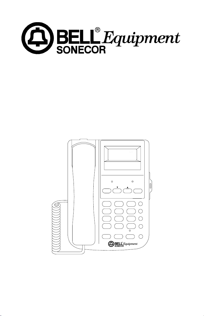
MODEL BE-70PS
70 NAME & NUMBER
CALLER-ID TELEPHONE
WITH SPEAKERPHONE
CALL #
I0:40
I0:40 AM 2/08 3
I0:40 I0:40
I23-555-I3I3
I23-555-I3I3
I23-555-I3I3I23-555-I3I3
JOHN SMITH
NEW RINGER
DELETE DIAL
1
GHI JKL MNO
45
PQRS
7
*
FLASH MEMO SPK RD/P
NEW
2/08 3
2/08 3 2/08 3
REPEAT
DEF
ABC
2
3
6
WXYZ
TUV
89
#
0
STORE
M1
M2
M3
OWNER’S MANUAL
Please read this instruction manual carefully.
- 1 -
1
Page 2

IMPORTANT SAFETY INSTRUCTIONS
When using your telephone equipment, basic safety precautions should always be
followed to reduce the risk of fire, electrical shock, and injury to persons including
the following:
1. Read and understand all instructions.
2. Follow all warnings and instructions marked on the product.
3. Unplug this product from the wall outlet before cleaning. Do not use liquid
cleaners, or aerosol cleaners. Use a damp cloth for cleaning. If necessary, use
a mild soap.
4. Do not use this product near water, for example near a bath tub, wash bowl,
kitchen sink, or laundry tub, in a wet basement, or near a swimming pool.
5. Do not place this product on an unstable cart, stand or table. The product may
fall, causing serious damage to the product.
6. This product should be operated only from the type of power source indicated
on the marking label. If you are not sure of the type of power supply to your
home, consult your dealer or local power company.
7. Do not allow anything to rest on the telephone line cord. Do not locate this
product where the cord will be abused by persons walking on it.
8. Never push objects of any kind into this product through the cabinet slots as
they may touch dangerous voltage points or short out parts that could result in
a risk of fire or electric shock. Never spill liquid of any kind on the product.
9. To reduce the risk of electric shock, do not disassemble this product, but take
it to a qualified serviceman when some service or repair work is required.
Opening or removing covers may expose you to dangerous voltages or other
risks. Incorrect reassembly can cause electric shock when the appliance is
subsequently used.
10. Unplug this product from the wall outlet and refer to qualified service personnel
under the following conditions:
a. When the power supply cord or plug is damaged or frayed.
b. If liquid has been spilled into the product.
c. If the product has been exposed to rain or water.
d. If the product does not operate normally by following the operating
instructions. Adjust only those controls, that are covered by the operating
instructions because improper adjustment of other controls may result in
damage and will often require extensive work by a qualified technician to
restore the product to normal operation.
e. If the product has been dropped or the cabinet has been damaged.
f. If the product exhibits a distinct change in performance.
11. Avoid using a telephone (other than a cordless type) during an electrical storm.
There may be a remote risk of electrical shock from lightning.
12. Do not overload wall outlets and extension cords as this can result in the risk
of fire or electrical shock.
13. Do not use the telephone to report a gas leak in the vicinity of the leak.
SAVE THESE INSTRUCTIONS
- 3 -
3
Page 3

BATTERY CAUTIONARY INSTRUCTIONS
CAUTION - To Reduce the Risk of Fire or Injury to Persons, Read and Follow
these Instructions.
1. Use only the following type and size of batteries: One alkaline 1604 size 9
volt type or equivalent battery.
2. Do not dispose of the battery in a fire. The cell may explode. Check with
local codes for possible special disposal instructions.
3. Do not open or mutilate the battery. Released electrolyte is corrosive and
may cause damage to the eyes or skin. It may be toxic if swallowed.
4. Exercise care in handling batteries in order not to short the battery with
conductor material such as rings, bracelets, and keys. The battery or
conductor may overheat and cause burns.
5. Do not attempt to recharge the battery provided with or identified for use
with this product by heating them. The batteries may leak corrosive
electrolyte or explode.
6. Do not attempt to rejuvenate the battery provided with or identified for
use with this product by heating them. Sudden release of the battery
electrolyte may occur causing burns or irritation to eyes or skin.
7. All batteries should be replaced at the same time. Mixing fresh and
discharged batteries could increase internal cell pressure and rupture the
discharged batteries.
8. When inserting batteries into this product, the proper polarity or direction
must be observed. Reverse insertion of batteries can cause charging,
which may result in leakage or explosion.
9. Remove the batteries from this product if the product will not be used for
a long period of time (several months or more) since during this time the
battery could leak, damaging in the product.
10. Discard “dead” batteries as soon as possible since “dead” batteries are
more likely to leak in a product.
11. Do not store this product, or the batteries provided with or identified for
use with this product in high-temperature areas. Batteries that are stored
in a freezer or refrigerator for the purpose of extending shelf life should
be protected from condensation during the storage and defrosting.
Batteries should be stabilized at room temperature prior to use after cold
storage.
- 4 -
4
Page 4

TABLE OF CONTENTS
Features
Introduction
Control Locations
Installation
Operation
Care and Maintenance
Trouble Shooting
FCC Requirements
........................................................................................................6
...................................................................................................7
.........................................................................................8
..................................................................................................10
Battery Installation .................................................................................10
Setting the Display Language ................................................................11
Setting the Area Code ...........................................................................11
Setting the Current Date and Time ........................................................11
Wall Mounting over a telephone jack .....................................................12
Wall Mounting ........................................................................................14
....................................................................................................16
Setting the Ringer Off/Low/Hi Switch .....................................................16
Setting the Tone/Pulse Switch ...............................................................16
Making Calls ..........................................................................................16
Receiving Calls ......................................................................................16
Using the Speakerphone .......................................................................16
Using the Call Timer ..............................................................................17
Using the Pulse to Tone Dialing feature .................................................17
Using the Flash Button ..........................................................................17
Using the Pause Function ......................................................................17
Using the Redial Feature .......................................................................17
Storing Telephone Numbers into One Touch Memory ...........................18
Dialing Telephone Numbers from One Touch Memory ..........................18
Storing Telephone Numbers into Two Touch Memory ...........................18
Dialing Telephone Numbers from Two Touch Memory ..........................18
Using Chain Dialing ...............................................................................19
Caller-ID Display Information .................................................................19
Reviewing Calls .....................................................................................20
Deleting Individual Call Records ............................................................21
Deleting All Call Records .......................................................................21
Using the Call Back feature ...................................................................22
Low Battery Indication ...........................................................................22
Memory Index ........................................................................................22
................................................................................23
........................................................................................24
.....................................................................................25
Equipment Notes ...................................................................................25
Interference Information .........................................................................25
- 5 -
5
Page 5

FEATURES
The BE-70PS with Caller-ID incorporates 70 name and number Caller-ID
memories into a single line telephone for convenient use.
3-Line Liquid Crystal Display Shows:
The caller’s name and number*
•
Time and date of the call
•
Total number of calls received
•
Total number of new calls received
•
New call indication
•
Repeat call indication
•
Out of area call indication
•
Blocked call indication
•
Line error indication
•
No data sent indication
•
Real time clock display
•
User Features Include:
Single button redial of displayed number
•
Selectively or collectively erase stored calls
•
3 Language operation (English, French, and Spanish)
•
New call LED
•
Hands free duplex speakerphone
•
Three one touch memories
•
Last-number redial
•
Call timer
•
Flash button
•
Add Pause to dialing
•
Ringer Off/Low/Hi select switch
•
Tone/Pulse select switch
•
Pulse to Tone switching during dialing
•
Desk or wall mountable
•
Display of dialed number
•
Uses 9 volt backup battery (not included)
•
∗ Requires telephone company provided Caller-ID Name and Number
service.
- 6 -
6
Page 6

INTRODUCTION
Congratulations on your purchase of the BE-70PS Caller-ID speakerphone.
The BE-70PS provides you with a variety of telephone features plus access to
the Caller Identification Delivery service that may be offered by your local telephone company.
IMPORTANT: You must first subscribe to Caller-ID service for your BE70PS telephone Caller-ID features to function. Contact your local telephone company to arrange to have Caller-ID service installed on your
line. There is an extra charge added to your monthly telephone bill for
this service.
1. The BE-70PS Caller-ID feature can be used to screen unwanted calls,
eliminate harassment from annoying calls, or to get prepared before answering a call.
2. After the first ring, the BE-70PS displays the name and telephone number
of the person calling, along with the date and time of the call before you
pick up your telephone.
3. The BE-70PS retains a record of the above information for each the last 70
calls received, including those that were received while you were away.
Getting Started
Unpack the unit and check that you have all the items that come with your
telephone.
1. BE-70PS Caller-ID telephone.
2. Coiled handset cord.
3. Long telephone line cord.
4. Short telephone line cord.
5. Wall mounting bracket.
6. Two self tapping screws.
Two mounting plugs.
7.
- 7 -
7
Page 7
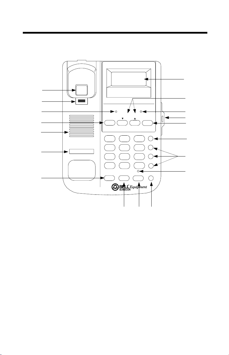
CONTROL LOCATIONS
Figure 1
1
2
3
4
5
6
7
NEW
3- I8
3- I8 PM 2:39
3- I8 3- I8
9I4-968-553I 02
BROWN JOHN
NEW RINGER
DELETE DIAL
ABC
1
GHI JKL MNO
45
PQRS
TUV
89
7
0
*
FLASH MEMO SPK RD/P
REP
2:39
#
2:39 2:39
STORE
DEF
2
3
6
WXYZ
#
11
12
13
14
15
16
M1
M2
M3
17
18
8 9 10
1. Hook Switch 2. Handset Hanger Tab
3. NEW Call LED 4. DELETE Button
5. Speaker 6. Telephone Number Paper
7. FLASH Button 8. MEMO Button
9. SPK Button 10. RD/P Button
11. LCD Display 12. REVIEW UP/DOWN Buttons
13. Ringer LED 14. Memory Index
15. DIAL Button 16. STORE Button
17. M1, M2, M3, Memory Buttons 18. SPK LED
19. VOLUME Control 20. Tone/Pulse Switch
21. Ringer OFF/LOW/HI Switch 22. Handset Cord Jack
23. Telephone Line Jack 24. Headset Volume Control
- 8 -
8
Page 8
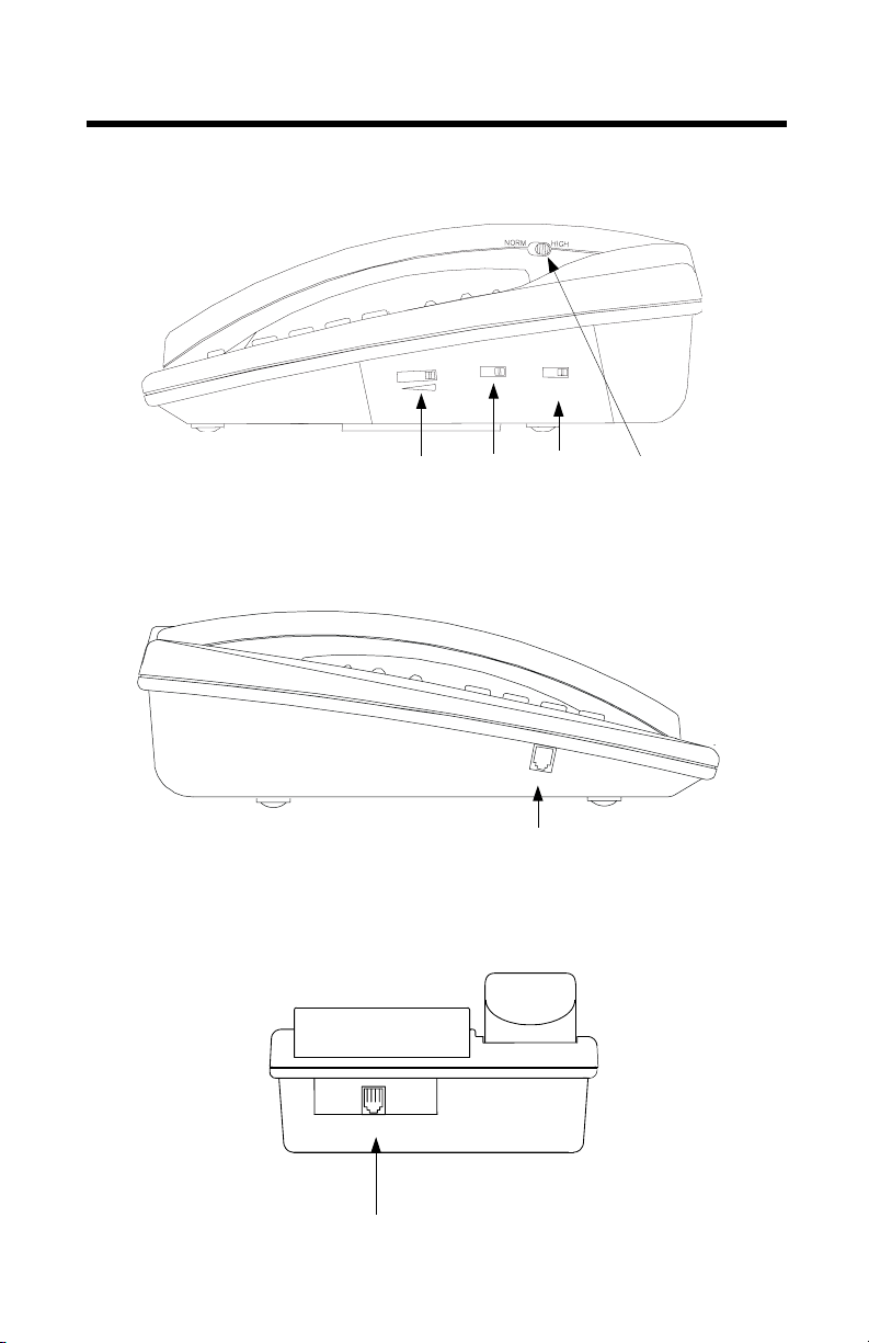
CONTROL LOCATIONS - continued
Figure 2
Right Side View
P
T
E
M
U
L
O
V
19 20 21 24
Figure 3
Left Side View
R
E
G
N
I
R
I
H
W
O
L
W
O
L
Figure 4
Rear View
TEL LINE
23
- 9 -
9
H
A
22
N
D
S
E
T
Page 9

INSTALLATION
Battery Installation
For Caller-ID operation, the BE-70PS requires one rectangular 9 volt battery
(not included). To install or change the battery, follow these steps.
WARNING: ALWAYS DISCONNECT THE TELEPHONE LINE FROM THE WALL OUTLET
BEFORE SERVICING OR DISASSEMBLING THIS EQUIPMENT OR REPLACING BATTERIES.
1. Use a small Philips head screw driver to remove the battery cover safety
locking screw.
2. Open the battery compartment by placing the edge of your fingernail under
the battery door latch and lifting upwards. See Figure 5
3. Lift the battery door up and remove from the unit.
4. If you are replacing a discharged battery, install a fresh battery within 15
seconds. Taking more time to replace the old battery can result in the loss
of call information that is stored in memory.
5. Install a new 9 volt battery, taking care to observe proper battery polarity.
Figure 5
Battery Compartment View
9 VOLT BATTERY
6. The
call LED and all the segments of the display will light for approxi-
NEW
mately two seconds followed by the firmware version.
7. Next,
"SET LANGUAGE"
will appear in the display.
8. Proceed immediately to set the correct display language as required. If you
hesitate more than 30 seconds or skip the following procedure, the display
will go to the stand by screen.
- 10 -
10
Page 10

INSTALLATION - continued
Setting the Display Language
The display will show
be flashing, confirming the current display language is set to English.
1. Press the review UP button if required until the desired language is flashing,
E (ENGLISH), F (FRENCH) or S (SPANISH).
2. Press the
FLASHING
DELETE
"SET LANGUAGE"
button to retain the language you have selected.
SET LANGUAGE
as well as
E F S
E F S
E F SE F S
"E F S"
. The
"E"
will
Setting the Area Code
The display will change to indicate
digit of the area code will be blinking.
1. Press the review UP or
area code. Press the
2. Press the review UP or
area code. Press the
3. Press the review UP button as required to select the
4. Once the correct area code is shown on the display, press the
to confirm the setting.
FLASHING
DELETE
DELETE
button as required to select the
DOWN
button to shift to the next digit.
button as required to select the
DOWN
button to shift to the next digit.
SET AREA CODE
"000"
000
000
000000
and
"SET AREA CODE"
rd
digit of the area code.
3
. The first
st
digit of the
1
nd
digit of the
2
DELETE
button
Setting the Time and Date
The display will change to indicate
The
in the hour segment will be blinking.
"12"
"12:00
PM
1/01"
and
"SET TIME/DATE"
.
FLASHING
I2:00
I2:00 PM I/0I
I/0I
I2:00 I2:00
I/0I I/0I
SET TIME/DATE
- 11 -
11
Page 11

INSTALLATION - continued
1. It is not necessary to enter the correct time and date when installing the
telephone.
2. The correct time and date is automatically set during the first call and is
updated each time Caller-ID information is received.
3. Press the
The display will go to Stand-By Screen mode as shown below.
4. After completing the above setup procedure, changes can be made to any
of the settings. Press and hold the
DOWN
5. Replace the battery cover and install the safety locking screw. Take care
not to over tighten the screw.
DELETE
button while in the Stand-By Screen mode.
Wall mounting over a wall jack
The BE-70PS can be directly mounted to a RJ-11W wall jack that contains
two mounting studs.
1. Reverse the handset
tion. This is done by removing the
cavity and re-installing it in the opposite direction. See Figure 6
2. Plug the short telephone cord (included) into the
the rear of the BE-70PS telephone.
3. Press the telephone line cord into the recess provided for it. See Figure 4
Figure 6
button once to end the setting of time and date mode.
TOTAL 00 NEW 00
HANGER TAB
I2:00
I2:00 PM I/0I
I/0I
I2:00 I2:00
I/0I I/0I
DELETE
button, then press the review
so that it is in the wall mounting posi-
HANGER TAB
from the upper handset
TEL LINE
jack located in
- 12 -
12
Page 12

INSTALLATION - continued
Figure 7
Rear View
Wall
Mounting
Bracket
Telephone
Cord Recess
RJ-11W Jack
Figure 8
Wall Mounting View
WALL
- 13 -
13
WALL
Page 13

INSTALLATION - continued
4. Install the telephone wall mounting bracket to the bottom surface of the
telephone. See Figure 7
5. Plug the coiled cord into the modular jack located on the handset.
6. Plug the remaining end of the coiled cord into the handset jack located on
the left side of the telephone. Place the handset into the cradle.
7. Plug the remaining end of the short telephone cord into the telephone wall
jack. See Figure 7
8. Slide the two slots located on the wall mounting bracket over the two
mounting studs on the telephone wall jack. See Figure 8
9. Carefully press downward until the telephone is secured to the jack.
Wall mounting
If the telephone wall jack does not have a face plate containing two mounting
studs, the BE-70PS can be mounted to the wall using two self-tapping screws
(supplied). Follow the previous instructions but with the following changes.
1. Choose a mounting location for the telephone that is less than seven (7)
feet away from the telephone. See Figure 10
2. If you are mounting the wall bracket to a plaster board wall surface, it is
necessary to first drill two
anchors into the wall. See Figure 9
3. Install the two self tapping screws at a distance of 3
from each other and located on a vertical center line. See Figure 9
4. Press a plastic anchor into each of the two holes. Tap the anchor into the
wall with a hammer until the anchor is completely seated.
5. Insert a screw into each mounting hole and tighten each screw with a
screwdriver.
4. Tighten each screw just enough to allow the wall mounting bracket enough
clearance to slip snugly over each screw head. Continue to tighten the two
screws until the bracket is secure. Do not over tighten the screws.
5. Connect one end of the long telephone line cord into the
located on the telephone.
6. Press the telephone line cord into the groove located on the back of the
telephone so that it is flush.
7. Install the telephone to wall mounting bracket, make sure that it is secure
prior to use.
8. Connect the remaining end of the telephone cord into an existing telephone
jack.
3
/16 inch holes to install the two expanding plastic
29
/32 inches (100 mm)
TEL. LINE
jack
- 14 -
14
Page 14

INSTALLATION - continued
Figure 9
Wall Mounting Guide
3 29/32 Inches
Mounting Screw
Mounting Screw
EXPANSION SELF-TAPPING
ANCHOR SCREW
- 15 -
15
Page 15

OPERATION
Using the Ringer Off/Low/Hi Switch
The
Off/Low/Hi switch
1. Set the
2. Set the
3. Set the
Off/Low/Hi
Off/Low/Hi
Off/Low/Hi
can be used to set the sound level of the ringer.
switch to the
switch to the
switch to the
position for normal operation.
Hi
position for less sound.
Low
position for no sound.
Off
Setting the Tone/Pulse Switch
Your telephone can operate in tone or pulse dialing mode.
1. Set the
you have, set the
2. Lift the handset and dial your number. If the dial tone continues, you have
pulse service, set the
switch to the desired position. If you're not sure which service
T/P
switch to the tone, T position. See Figure 2
T/P
switch to the pulse, P position.
T/P
Making Calls
To make a call, lift the handset or press the
1. When dial tone is heard, dial the desired number.
2. The handset icon as well as the number being dialed will be indicated in
the display.
3. Hang up when you finish your call. Within 10 seconds, the display will return to Stand-By Screen mode.
button once.
SPK
Receiving Calls
When the telephone rings, the
Important: Do not answer incoming calls until the second ring occurs.
This is necessary so that the Caller ID information can be received.
1. Lift the handset or press the
2. The
HANDSET
for the duration of the call.
3. If necessary, adjust the
telephone headset to a comfortable receive level. See Figure 2
4. Hang up when you finish your call. Within 10 seconds, the display will return to the Stand-By Screen.
RINGER
SPK
icon as well as the Caller-ID information will be displayed
VOLUME
LED will flash.
button once.
control located on the right side of the
Using the Speakerphone
You can make or receive calls using the speakerphone.
- 16 -
16
Page 16

OPERATION - continued
1. Press the
2. Adjust the
to a comfortable receive level.
3. You may pick up the handset at anytime and speakerphone will be cancelled automatically.
4. When you have finished your call, press the
go out.
Using The Call Timer
The telephone has a built in timer that begins timing your calls five seconds
after you pick up the handset or press the
1. The call timer will turn off after you hang up.
button, the
SPK
VOLUME
LED will light.
SPK
control located on the right side of the telephone base
button, the
SPK
button to make a call.
SPK
SPK
LED will
Using the Pulse to Tone Dialing feature
If you have rotary service, you can change from pulse dialing to touch tone
dialing during a call by pressing the
accessing long distance and tele-banking services.
1. The telephone will automatically return to pulse dialing mode after you
hang-up.
✳✳✳✳
key. This feature can be useful when
Using the Flash Button
The flash button allows you to easily access special telephone company features such as call waiting, three way calling, etc.
1. Press the
button to get a new dial tone without hanging up.
FLASH
Using the Pause Feature
The pause function allows you to insert a 3.6 second pause in the dialing sequence when accessing long distance or tele-banking services.
1. Press the
2. Additional pauses can be entered as required by pressing the
as required.
Using the Redial Feature
The last number dialed (up to 32 digits) is automatically stored in memory.
1. To redial the last number dialed, lift the handset or press the
2. When dial tone is heard, press the
the display as it is being dialed.
button at the desired point when dialing the number.
RD/P
button. The number will appear on
RD/P
RD/P
SPK
button
button.
- 17 -
17
Page 17

OPERATION - continued
Storing Telephone Numbers into One Touch Memory
Telephone numbers up to 16 digits can be stored in three one touch-memory
locations.
1. To store a number into one touch memory, lift the handset or press the
button, then press the
SPK
2. Dial the phone number that you wish to store. Pauses, or Pulse to Tone
switching can be included.
3. The number to be stored will appear on the display as it is being entered.
4. Press the M1,
tion selected, the new number will replace the previously stored number.
5. Hang up the handset or press the
or M3 button. If a number is already stored at the loca-
M2,
STORE
button.
button.
SPK
Dialing Telephone Numbers From One Touch Memory
To dial a number stored in one touch memory. lift the handset or press the
button.
SPK
1. When dial tone is heard, press M1, M2, or M3 button that has the number
stored that you want to dial.
2. The number will be displayed as it is being dialed.
Storing Telephone Numbers into Two Touch Memory
1. Lift the handset or press the
2. Press the
3. The number to be stored will appear on the display as it is being entered.
4. Press the
(0,1,2,….9).
5. Hang up the handset or press the
STORE
button, then dial the number that you want to store.
STORE
button again, then press one of the 10 dialing keys
SPK
button.
button.
SPK
Dialing Telephone Numbers From Two Touch Memory
1. Lift the handset or press the
2. Press the
that contains the number to be dialed.
3. The number will be displayed as it is being dialed.
button, then press one of the 10 dialing keys (0,1,2, …9)
MEMO
button to get dial tone.
SPK
- 18 -
18
Page 18

OPERATION - continued
Using Chain Dialing
Chain dialing allows you to dial a variety of numbers that have been previously stored into memory locations, in any combination.
1. Lift the handset or press the
2. When dial tone is heard, press the memory button that contains the number that you desire to dial.
3. Wait to hear the long distance access confirmation. Press another memory
location or use the keypad to enter the rest of the telephone number that
you wish to dial.
Caller-ID Display Information
When a telephone call is received, the Caller-ID information will be displayed
between the first and second ring. If you answer the call before the second
ring, information will not be displayed.
1. When a call is received, the caller’s name and number will be displayed if
available along with the time and date of the call.
2. If the caller's name or number is blocked by the sender, their name or number will not appear on the display. The display will indicate
.
CALL"
3. If the call is from out of your area code,
the display.
button.
SPK
CALL #
I0:40
I0:40 AM 2/08 3
I0:40 I0:40
I23-555-I3I3
I23-555-I3I3
I23-555-I3I3I23-555-I3I3
2/08 3
2/08 3 2/08 3
NEW
REPEAT
JOHN SMITH
AM
I0:40
I0:40
I0:40 I0:40
------------
------------
------------------------
2/08 3
2/08 3
2/08 3 2/08 3
BLOCKED CALL
"OUT OF AREA"
"BLOCKED
will appear on
AM
2/08 3
I0:40
I0:40
I0:40 I0:40
------------
------------
------------------------
2/08 3
2/08 3 2/08 3
-OUT OF AREA-
- 19 -
19
Page 19

OPERATION - continued
4. The new call information is displayed for about 20 seconds after the last
ring is received.
5. If the data received from the telephone company contains corrupted information, it can cause the display to indicate
Reviewing Calls
When you have received new calls, the
Stand-By Screen is displayed. The total number of calls received as well as
the number of new calls received, will be indicated on the display.
1. Press either the review UP or review
call records.
2. The
call record and will be removed after you have reviewed the call.
3. The
been received more than once. Only the call information for the most recent call will be recorded in memory.
call icon will appear in the display screen for each new incoming
NEW
REPEAT
call icon will be appear in the display if an incoming call has
-LINE ERROR-
TOTAL 05 NEW 00
I23-555-I3I3
I23-555-I3I3
I23-555-I3I3I23-555-I3I3
JOHN SMITH
"LINE ERROR"
call LED will flash when the
NEW
I2:00
I2:00 AM I/0 I
I2:00 I2:00
I0:40
I0:40 AM 2/08 3
I0:40 I0:40
I/0 I
I/0 I I/0 I
button to review the incoming
DOWN
CALL #
2/08 3
2/08 3 2/08 3
NEW
REPEAT
.
NEW CALL
CALL #
I0:40
I0:40 AM 2/08 3
I0:40 I0:40
I23-555-I3I3
I23-555-I3I3
I23-555-I3I3I23-555-I3I3
2/08 3
2/08 3 2/08 3
NEW
REPEAT
JOHN SMITH
- 20 -
20
REPEAT CALL
Page 20

OPERATION - continued
4. Once you have reviewed all the new call records, the repeat call indicator
will not be displayed.
5. When you have reviewed all call records,
the display.
6. If the
Stand-By Screen, there are new calls that you have not yet reviewed.
7. If you have not have any calls in memory, the display will remain in the
Stand-By Screen.
8. The Caller-ID information for the last 70 calls received is automatically
stored in memory. After 70 calls have been received, new call records will
replace the oldest call records.
call LED is still flashing when the display goes back to the
NEW
Deleting Individual Call Records
When you are reviewing a call record, you can delete an individual call record
from memory by following these steps:
1. Press the review UP or review
wish to delete.
2. Rapidly press the
3. After you have erased the call record, the display will show the next call
record.
Deleting All Call Records
While you are reviewing an individual call record, you can delete the all calls
in memory.
1. Press either the review UP or review
cords mode.
2. Press and hold the
3. All call records will be deleted and the display will indicate the Stand-By
Screen. The display will indicate
-END OF LIST-
DELETE
DELETE
"END OF LIST"
button to locate the call record you
DOWN
button twice to erase the call record.
DOWN
button for about 5 seconds.
"TOTAL 00 NEW 00".
button to enter review call re-
will appear on
- 21 -
21
Page 21

OPERATION - continued
LOW BATTERY
ICON
LOW
I:30
I:30 PM 2/08
2/08
I:30 I:30
2/08 2/08
TOTAL 05 NEW 00
Using the Call Back feature
The Call Back feature allows automatic dialing of the telephone number
shown in the display. For calls received within your local area code, the area
code will automatically be removed.
1. Press the review UP or
2. Pick up the handset or press the
3. When dial tone is heard, press the
button to select the number to call.
DOWN
button.
SPK
button to automatically call the
DIAL
phone number shown on the display.
4. If the telephone number being dialed has a different area code than yours,
will be automatically added to the dialing sequence.
"1"
5. The
HANDSET
icon will flash in the upper left hand corner of the display
while dialing.
Low Battery Indication
If the memory backup battery power is low, the
LOW BATTERY
symbol will
appear in the display.
1. Replace the battery as soon as possible to assure reliable operation.
Memory Index
The BE-70PS telephone has a pull out drawer located on the right side of the
telephone which contains a index card. This index card can be used to remind
you of the names and telephone numbers that you have entered in each of
the memory locations.
Figure 10
NEW
REP
#
3- I8
3- I8 PM 2:39
2:39
3- I8 3- I8
2:39 2:39
9I4-968-553I 02
BROWN JOHN
NEW RINGER
DELETE DIAL
- 22 -
22
Memory
Index
Page 22

CARE AND MAINTENANCE
Your Caller-ID telephone has been designed to give years of trouble free service. It is a sensitive electromechanical instrument. To assure its longevity,
please read the following maintenance instructions.
1. Keep the telephone away from heat as high temperatures can shorten the
life of the electrical components and distort or melt its plastic parts.
2. The telephone should be kept free of dust and moisture. If it gets wet, wipe
it dry immediately. Liquids can contain minerals that can corrode electronic
circuits.
3. Handle your telephone gently and carefully. Dropping it can cause serious
damage to circuitry, or the plastic case, which may result in causing it to
malfunction.
4. Do not use any type of chemical or any abrasive powder to clean the cabinet. Use only mild detergents on a soft, damp cloth to clean the telephone.
5. Your telephone has built-in surge protection circuits that meet or exceed
FCC requirements. However, an incident such as a lightning strike at or
near the telephone lines, could cause series damage.
6. If installed in an area with frequent or severe electrical storms, it is suggested that the telephone be disconnected during these storms or that additional surge suppression equipment be added to the installation.
7. In the case of trouble with the telephone, do not attempt to repair the telephone yourself. It is the responsibility of users requiring service to report
the need for service to our Service Department. They will make the necessary arrangements for repair or replacement.
6. If you should have any questions about the operation of your BE-70PS
Caller-ID telephone, please call our Service Department at
between the hours of 9:00 A.M. and 4:30 P.M.,
eastern time. Or you may contact TT Systems LLC for technical assistance via
our Internet Website
http://www.ttsystems.com
914-968-2100
Monday
.
through
Friday
,
- 23 -
23
Page 23

TROUBLESHOOTING
The display screen is blank. Possible causes of the problem are:
1. The battery needs to be replaced.
No Dial Tone. Possible causes of the problem are:
1. The telephone line cord is not plugged in properly at the telephone jack or
at the telephone.
2. Test the telephone using a different telephone jack, if it works, the first jack
may be defective.
Have Dial Tone but cannot break dial tone. Possible causes of the problem are:
1 Check that the T/P switch is set to the correct mode.
Does not display Caller-ID information. Possible causes of the problem
are:
1. Confirm that your local telephone company has activated Caller-ID service.
2. Caller-ID information is sent by the telephone company between the first
and second rings. If the call is answered before the second ring, the CallerID information may not be received correctly.
3. If a telephone answering machine is connected to the same phone line, it
must be set to answer in two or more rings.
Error appears in the display. Possible causes of the problem are:
1. Bad data may have been received. This may be due to a transmission or
reception error. It is recommended to erase call records that have a error
indication.
Cannot dial a call record. Possible causes of the problem are:
1. Confirm that you programmed your local area code into the telephone. If
not, reprogram the area code again.
- 24 -
24
Page 24

FCC REQUIREMENTS
Equipment Notes
This equipment is registered with the Federal Communications Commission
and is in compliance with Part 68 of the FCC Rules and Regulations. On the
bottom of this equipment is a label indicating among other information, the
FCC Registration Number and Ringer Equivalence Number (REN) for this
equipment. Upon request, you must provide this information to your telephone
company. The REN useful to determine the quantity of devices you may connect to your telephone line and still have all of those devices ring when your
telephone number is called. In most, but not all areas, the sum of the REN's of
all devices connected to one line should not exceed five (5).
The BE-70PS telephone cannot be used on coin service pay telephones.
•
The BE-70PS telephone cannot be connected to party lines.
•
The BE-70PS telephone is Hearing Aide Compatible
•
If you experience trouble with this telephone equipment, disconnect it from the
telephone network until the problem has been corrected. The telephone company may discontinue service if your telephone equipment causes harm to the
telephone network. In this case, the telephone company will:
Notify the customer that service is being discontinued.
•
Provide the customer with the opportunity to correct the situation.
•
Inform the customer of their right to file a complaint with the FCC.
•
Interference Information
This equipment generates and uses and can radiate low level radio frequency
energy. It has been tested and found to comply with the limits for a Class B
digital device in accordance with the specifications in Part 15 of the FCC
Rules, which are designed to provide reasonable protection against such interference in a residential installation. If this equipment does cause interference to radio or television reception, which can be determined by unplugging
it from the telephone line. If the interference is caused by the BE-70PS, the
user is encouraged to try to correct the interference by one or more of the following measures:
Reorient the radio or TV receiving antenna.
•
Relocate this device with respect to the receiver.
•
Move this device away from the receiver.
•
If necessary, the user should consult the dealer or an experienced radio/
television technician for additional suggestions. The user may find the following booklet, prepared by the Federal Communications Commission, helpful.
This booklet is available from the U.S. Government printing Office. There may
be a charge for this booklet.
"How to Identify and Resolve Radio-TV Interference Problems"
U.S. Government printing Office
Washington, D.C. 20402
Stock Number. 004-000-00354-4
- 25 -
25
Page 25

02A00
- 28 -
28
 Loading...