

Page 1
BELLSYSTEM PRACTICES SECTON503-200-104
AT&TCo Standard Issue2, February 1975
TELEPHONE SETS
940-TYPE
IDENTIFICATION, INSTALLATION, AND CONNECTIONS
1. GENERAL
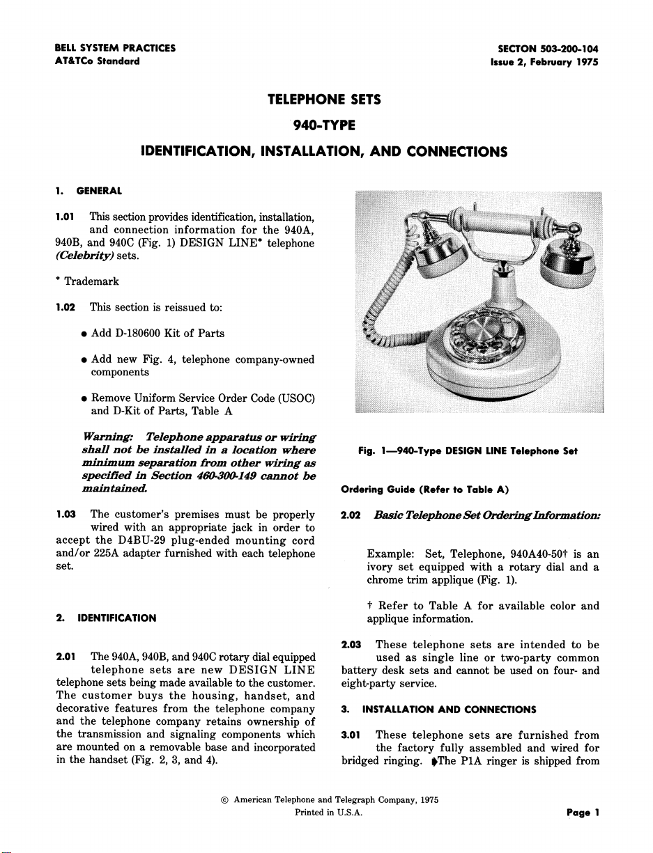
1.01 This section provides identification, installation,
and connection information for the 940A,
940B, and 940C (Fig. 1) DESIGN LINE* telephone
(Celebrity) sets.
* Trademark
1.02 This section is reissued to:
e Add D-180600 Kit of Parts
e Add new Fig. 4, telephone company-owned
components
e Remove Uniform Service Order Code (USOC)
and D-Kit of Parts, Table A
Warning: Telephone apparatus or wiring
shall not be installed in a location where Fig. l1940-Type DESIGN LINETelephone Set
minimum separation from other wiring as
speciHed in Section 46_30_149 cannot be
m_dnt_dned. Ordering Guide (Refer to Table A)
1.03 The customer's premises must be properly 2.02 Basic Telephone SetOrderinglrfforma_on:
wired with an appropriate jack in order to
accept the D4BU-29 plug-ended mounting cord
and/or 225A adapter furnished with each telephone Example: Set, Telephone, 940A40-50t is an
set. ivory set equipped with a rotary dial and a
2. IDENTIFICATION applique information.
2.01 The 940A, 940B, and 940C rotary dial equipped used as single line or two-party common
telephone sets are new DESIGN LINE battery desk sets and cannot be used on four- and
telephone sets being made available to the customer, eight-party service.
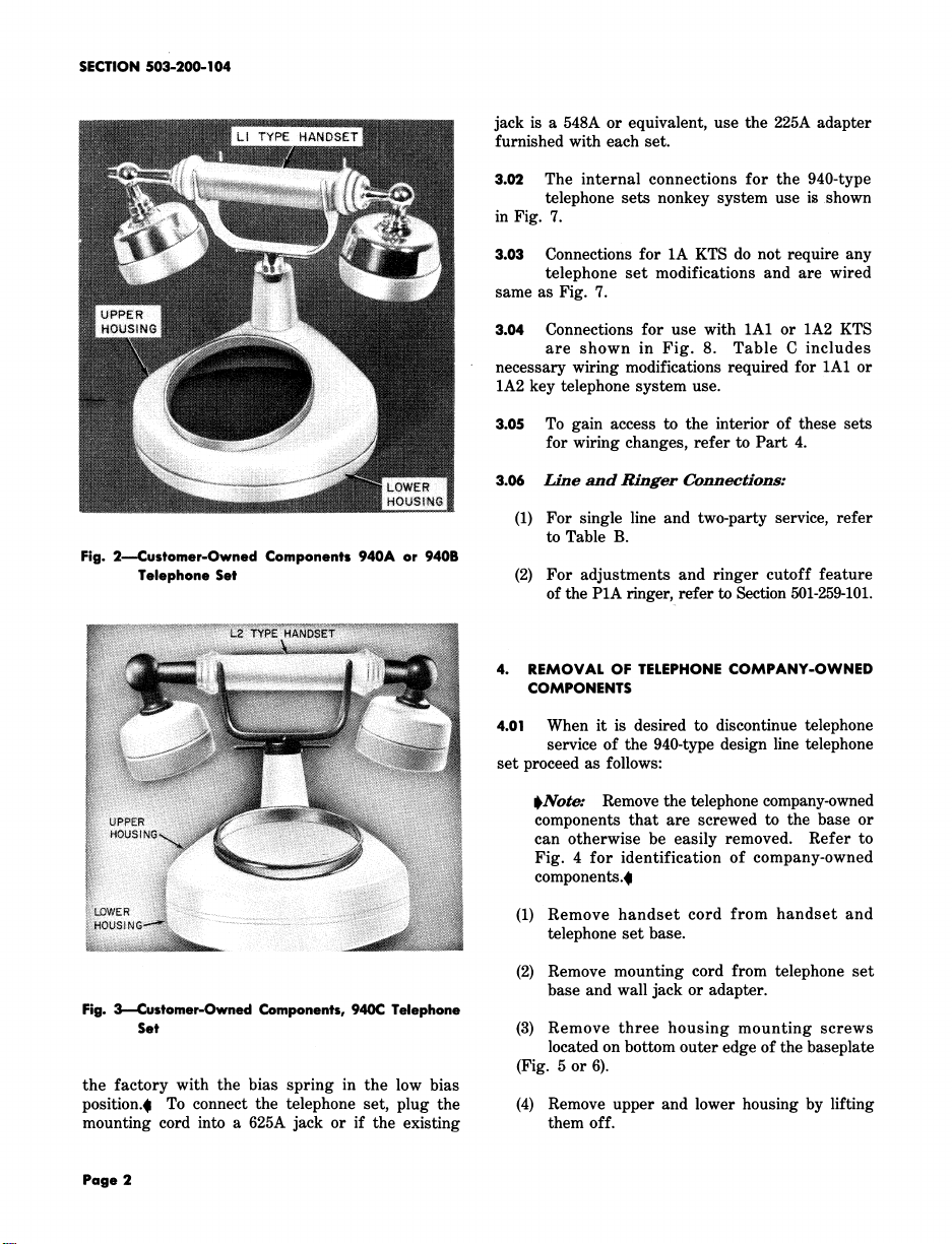
The customer buys the housing, handset, and
decorative features from the telephone company 3. INSTALLATIONAND CONNECTIONS
and the telephone company retains ownership of
the transmission and signaling components which 3.01 These telephone sets are furnished from
are mounted on a removable base and incorporated the factory fully assembled and wired for
in the handset (Fig. 2, 3, and 4). bridged ringing. $The P1A ringer is shipped from
© American Telephone and Telegraph Company,1975
Printed in U.S.A. page 1
chrome trim applique (Fig. 1).
t Refer to Table A for available color and
2.03 These telephone sets are intended to be
Page 2
SECTION503-200-104
jack is a 548A or equivalent, use the 225A adapter
furnished with each set.
3.02 The internal connections for the 940-type
telephone sets nonkey system use is shown
in Fig. 7.
3.03 Connections for 1A KTS do not require any
telephone set modifications and are wired
same as Fig. 7.
3.04 Connections for use with 1A1 or 1A2 KTS
are shown in Fig. 8. Table C includes
necessary wiring modifications required for 1A1 or
1A2 key telephone system use.
3.05 To gain access to the interior of these sets
for wiring changes, refer to Part 4.
3.06 Line and Ringer Connections:
(1) For single line and two-party service, refer
to Table B.
Fig. 2--Customer-Owned Components 940A or 940B
Telephone Set (2) For adjustments and ringer cutoff feature
of the P1A ringer, refer to Section 501-259-101.
4. REMOVAL OF TELEPHONE COMPANY-OWNED
COMPONENTS
4.01 When it is desired to discontinue telephone
service of the 940-type design line telephone
set proceed as follows:
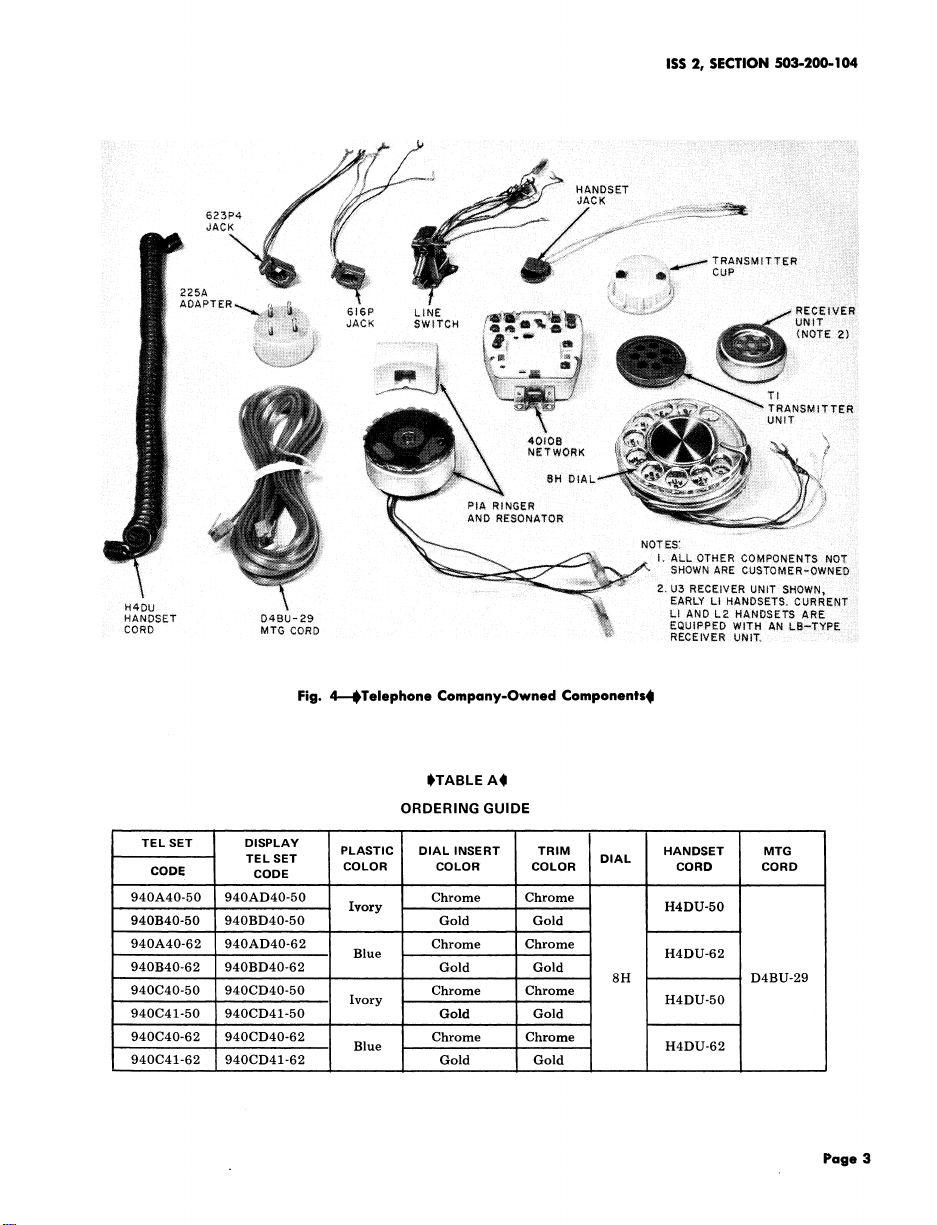
$Note: Remove the telephone company-owned
components that are screwed to the base or
can otherwise be easily removed. Refer to
Fig. 4 for identification of company-owned
components.41
(1) Remove handset cord from handset and
telephone set base.
(2) Remove mounting cord from telephone set
Fig. 3---Customer-Owned Components,940C Telephone
Set (3) Remove three housing mounting screws
the factory with the bias spring in the low bias
position._l To connect the telephone set, plug the (4) Remove upper and lower housing by lifting
mounting cord into a 625A jack or if the existing them off.
Page 2
base and wall jack or adapter.
located on bottom outer edge of the baseplate
(Fig. 5 or 6).
Page 3
ISS 2, SECTION 503-200-104
Fig. 4---OTelephone Company-Owned Components_l
STABLE A(I
ORDERING GUIDE
TEL SET DISPLAY
CODE CODE
TEL SET DIAL
940A40-50 940AD40-50 Chrome Chrome
940B40-50 940BD40-50 Ivory Gold Gold
940A40-62 940AD40-62 Chrome Chrome
........ Blue H4DU-62
940B40-62 940BD40-62 Gold Gold
940C40-50 940CD40-50 Chrome Chrome
940C41-50 940CD41-50 Gold Gold
940C40-62 940CD40-62 Chrome Chrome
940C41-62 940CD41-62 Gold Gold
..,
PLASTIC DIAL INSERT TRIM HANDSET MTG
COLOR COLOR COLOR CORD CORD
H4DU-50
8H D4BU-29
Ivory H4DU-50
Blue H4DU-62
Page 3
Page 4

SECTION 503-200-104
TABLE B
LINE AND RINGER CONNECTIONS
(940-TYPE TELEPHONE SETS)t
WIRE OR LEAD COLOR OR RING IDENTIFYING GROUND
PARTY NO IDENT
BRIDGED GROUND 1000_"_ 2650,(9.,
R R R R R R
InsideWire G G G G G G
INDIVID. TIP PARTY
atJack y y y y y y
_
BK B B B B B
R A A L1 F F
623P4 Line Cord G L1 L1 A L2 L2
Jack Assy
Y G G G G G
BK ...... L2 L2 L2 * *
R K K K K K
Ringer S-R * * * * L1
S * * * L1 *
BK L1 G G G G
Line Switch Y A A A L2 L2
W F F F B B
• Insulated and stored.
t For access to set wiring follow applicable steps in Part 4.
(5) After removing telephone company-owned
components reassemble upper and lower
housings using the three housing mounting screws
TABLE C
(Fig. 5 or 6).
MODIFICATIONS FOR 1A1 OR 1A2 KTS
(940-TYPE TE LEPHONE sET)* 4.02 Follow localprocedures for returning telephone
company-owned components.
NET TERM.
LEAD COLOR REMOVE CONNECT
S A ' L2 Western Electric for repair, it should be
Line
Switch BR C G
Y h L2 contains packing material and instructions.0
FROM TO 4.03 $When it is necessary to return a set to
packed using the D-180600 Kit of Parts which
G L1 A
W F C
623P4 Line Cord
Jack Assy
G L1 F
Ringer BK L1 F
* For access to set wiring follow applicable steps in Part 4.
Page 4
Page 5

Fig. 5--940A or 940B Telephone Set, Bottom View
ISS 2, SECTION 503-200-104
Fig. 6_940C Telephone Set, Bottom View
Page 5
Page 6

SECTION 503-200-104
Page 6
Page 7

ISS2, SECTION503-200-104
n- l--
n-
o___ _
._1 ._1"r
" _I iiii!iiii!i_
i_!iii_iii_i_iii!iii!iiiii_i_i_iii_iii____iiiii_ii__iiii_iiiiiii_iii_i_ii!i!_iiii__i_i_i_i_!iii__i_iiii!i___i)!iii___!i)iiii_iiii!i!iiiiiii_i_iiiiiiiiiiiiii;i;iiiiili)iiii!iiiiii;iiiiiiiiiiiiiiiiiiiiiiiiiiiii
_o
° I I
iiiii_iiiiiiiiii_i!iiiii_iiiii__iiiii_iii_i_i!i_i_i_i_i_ii_iiiiiiiii_ii!_ii_iiiii!i_i_iii_i!iiiiiii_iiiii_iii_i_iii_i_i_iiii__iii_iii)iii_i_i_i_iiiiiiiiiililililiiii!!i!i!i!iiiii!i!i!iiiiiiiii!i!iiiiiiiiiiiiiiiiiiiiiii!
.....
_j Z 0.
- I--
.1-
_ Cq
}v .5 ,_
Q:
0 _ ..1
_ .-
_ _ o
_o .... :,
___ o o _-
<
<
e
u
@
m
I--
Q.
,q,
..............................
::::::::::::::::::::::::::::::::::::::::::::::::::
_ _z
IIII
;iii!iiiiiiiiiiiiiiliiiii!iiii!ililiiii!iiiiiiiiiiii _ _ ,.
o z
m o
iii!iii!ili!iliiiiiiiiiiiiiiiiiiiili!iii_i!iii_iQ_i}-::iii::®iiiiiiiiiiiii 8 _ _,, ,.,,.,i, _ _ ,.
• ..__==_ , , ,
_iiiiiiilili!iiiiiiii!iiiiiiiiiiliiiiii!i!iiiiiiiiii!ili::iiii::)iii::::::i_!ii!:j::!ii::::!_i_i_!_::_::_::_::_::_ _ _ : ....
,., T,"'T''::t:: ............. _ o. z
'___"' '_' "---__1_-I /_I o- ,_ ,-, o
z } E:I r--I <1 <1 z
t-
Page 7
7 Pages
 Loading...