

Page 1
BELLSYSTEM PRACTICES SECTION 503-200-102
AT&TCo Standard Issue 1, June 1977
TELEPHONE SETS
902A1 AND 2902A1
1. GENERAL
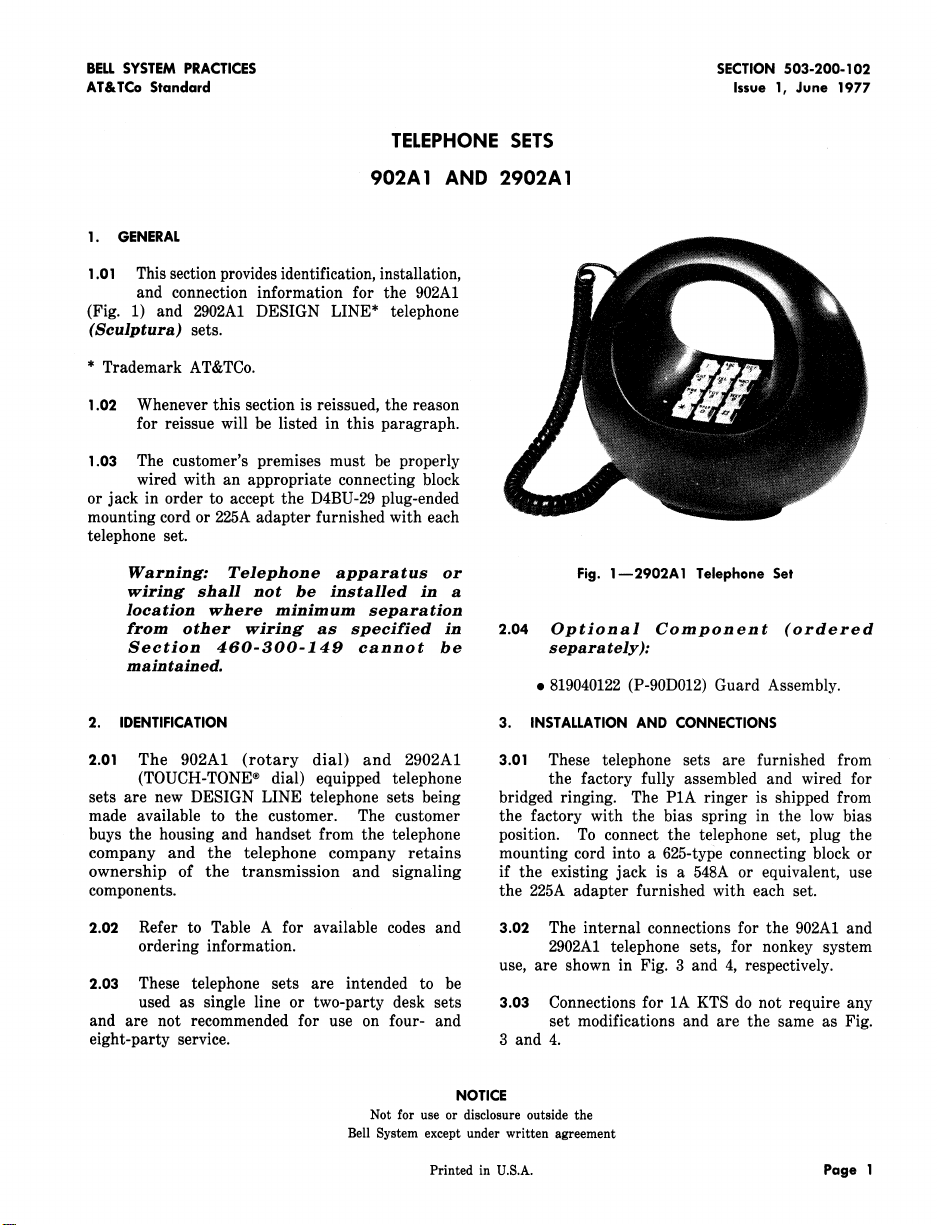
1.01 This section provides identification, installation,
and connection information for the 902A1
(Fig. 1) and 2902A1 DESIGN LINE* telephone
(Seulptura) sets.
* Trademark AT&TCo.
1.02 Whenever this section is reissued, the reason
for reissue will be listed in this paragraph.
1.03 The customer's premises must be properly
wired with an appropriate connecting block
or jack in order to accept the D4BU-29 plug-ended
mounting cord or 225A adapter furnished with each
telephone set.
Warning: Telephone apparatus or Fig. 1--2902A1 Telephone Set
wiring shall not be installed in a
location where minimum separation
from other wiring as specified in 2.04 Optional Component (ordered
Section 460-300-149 cannot be separately):
maintained.
e 819040122 (P-90D012) Guard Assembly.
2. IDENTIFICATION 3. INSTALLATIONAND CONNECTIONS
2.01 The 902A1 (rotary dial) and 2902A1 3.01 These telephone sets are furnished from
(TOUCH-TONE ® dial) equipped telephone the factory fully assembled and wired for
sets are new DESIGN LINE telephone sets being bridged ringing. The P1A ringer is shipped from
made available to the customer. The customer the factory with the bias spring in the low bias
buys the housing and handset from the telephone position. To connect the telephone set, plug the
company and the telephone company retains mounting cord into a 625-type connecting block or
ownership of the transmission and signaling if the existing jack is a 548A or equivalent, use
components, the 225A adapter furnished with each set.
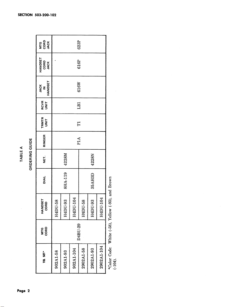
2.02 Refer to Table A for available codes and 3.02 The internal connections for the 902A1 and
ordering information. 2902A1 telephone sets, for nonkey system
2.03 These telephone sets are intended to be
used as single line or two-party desk sets 3.03 Connections for 1A KTS do not require any
and are not recommended for use on four- and set modifications and are the same as Fig.
eight-party service. 3 and 4.
Not for use or disclosure outside the
Bell System except under written agreement
Printed in U.S.A. Page 1
use, are shown in Fig. 3 and 4, respectively.
NOTICE
Page 2
SECTION 503-200-102
I-
-1-
Z
w
< _ _
_ N Z
N
0
Page 2
g _ N e
m
m _
_
_ ..
Page 3
ISS 1, SECTION 503-200-102
TABLE B
LINE AND RINGER CONNECTIONS
(902A1 TELEPHONE SET)
TIPPARTY
WIRE INDIVID, RING NO IDENT
OR COLOR OR PARTY IDENT GROUND
LEAD BRIDGED _,,
R R R R R R
Inside G G G G G G
Wire at .....
Conn Slk y y y y y y
BK B B B B B
R A A L1 F F
GROUND
1000,_ 2650_.,
623P4 G L1 L1 A L2 L2
Line Cord y G G G G G
Jack Assy
Ringer
Line BL-W A A A ....* *
Switch
BK L2 L2 L2 * *
R K K K K K
S-R * * * * L1
S * * * L1 *
BK L1 G G G' G
W F F F B B
BL C C C * *
BR L2 L2 L2 C C
s L2 L2 L2 A A
•Insulated and stored.
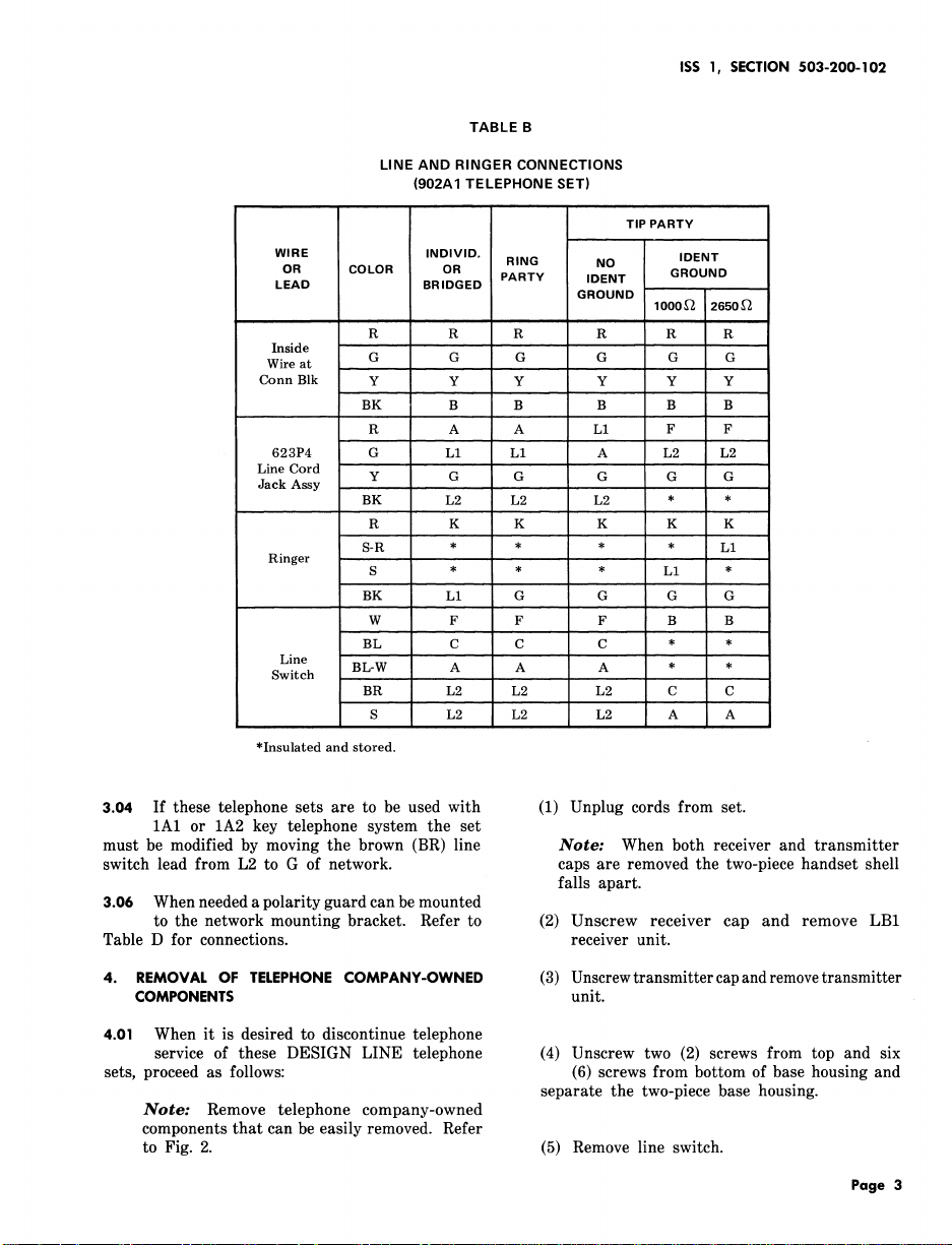
3.04 If these telephone sets are to be used with (1) Unplug cords from set.
1A1 or 1A2 key telephone system the set
must be modified by moving the brown (BR) line Note: When both receiver and transmitter
switch lead from L2 to G of network, caps are removed the two-piece handset shell
3.06 When needed a polarity guard can be mounted
to the network mounting bracket. Refer to (2) Unscrew receiver cap and remove LB1
Table D for connections, receiver unit.
4. REMOVAL OF TELEPHONE COMPANY-OWNED (3) Unscrew transmitter cap and remove transmitter
COMPONENTS unit.
4.01 When it is desired to discontinue telephone
service of these DESIGN LINE telephone (4) Unscrew two (2) screws from top and six
sets, proceed as follows: (6) screws from bottom of base housing and
Note: Remove telephone company-owned
components that can be easily removed. Refer
to Fig. 2. (5) Remove line switch.
falls apart.
separate the two-piece base housing.
Page 3
Page 4

SECTION 503-200-102
TABLE C
LINE AND RINGER CONNECTIONS
2902A1 TELEPHONE SET
TIP PARTY
WIRE INDIVID. IDENT
OR COLOR OR RING NO
LEAD BRIDGED PARTY IDENT GROUND
..........
GROUND
1000_., 2650
R R R R R R
Inside G G G G G G
Wire at
Conn Slk Y Y Y Y Y Y
BK B B B B B
R A A L1 C C
623P4 G L1 L1 A L2 L2
Line Cord y G G G G G
Jack Assy
BK L2 L2 L2 * *
R K K K K K
Ringer
S-R * * * * L1
S * * * L1 *
BK L1 G G G G
W F F F B B
G L1 L1 A L1 L1
..... _
Line BI_ ' C C C * *
Switch BL-W ....... A A L1 * *
BR L2 L2 L2 F F
S L2 L2 L2 A A
•Insulatedand stored,
(6) Unscrew one (1) network mounting bracket (10) Reassemble two-piece base housing and
screw and remove 4228-type network, replace two top and six bottom screws.
(7) Unscrew four (4) dial bracket mounting (11) Reassemble two-piece handset shell and
screws and take out base-weight, screw on the receiver and transmitter caps.
(8) Unscrew two (2) ringer mounting screws 4.02 Follow local procedures for returning telephone
and remove P1A ringer, company-owned components.
(9) Loosen two (2) dial mounting screws and 4.03 When it is desired to return a set to Western
remove dial from dial brackets. Electric for repair, it should be packed using
D-180600 Kit of Parts which contains packing
material and instructions.
Page 4
Page 5

ISS 1, SECTION 503-200-102
LINE 35- TYPE MOUNTING 4228 -TYPE
SWITCH DIAL SCREW NETWORK
DIAL BRACKET 616P JACK
MOUNTING ASSEMBLY
SCREWS(4)
NETWORK
625P4 JACK BASE-WEIGHT P-TYPE
ASSEMBLY ' RINGER
Fig. 2--2902A1 Telephone Set With Two-Piece Housing Separated
Page 5
Page 6

SECTION 503-200-102
TABLE D
POLARITY GUARD CONNECTIONS
FOR 2902A1 TELEPHONE SET
819040122 (P-90D012) GUARD ASSEMBLY
DIS-
CON- CONNECT
NECT TO
LEAD COLOR FROM
NET. NET.
L
.....
POLA RITY
Dial BK RR T
Line BL
Switch (Note 1)
623P4
Line Cord
R
C S
Jack Assy. (Note 2 ) _
Polarity G RR
Guard
W C
Notes:
1. If wired for bridged service, ring party, tip party
with no identification ground, or 1A1 or 1A2 KTS.
2. If wired for tip party with identification ground,
GUARD
Page 6
Page 7

ISS 1, SECTION 503-200-102
Page 7
Page 8

SECTION 503-200-102
Page 8
8 Pages
 Loading...