

Page 1

Wireless G Plus MIMO
Router
Belkin Tech Support
US: 877-736-5771
310-898-1100 ext. 2263
Europe: 00 800 223 55 460
Australia: 1800 235 546
New Zealand: 0800 235 546
Singapore: 800 616 1790
Belkin Corporation
501 West Walnut Street
Los Angeles, CA 90220, USA
310-898-1100
310-898-1111 fax
Belkin Ltd.
Express Business Park, Shipton Way
Rushden, NN10 6GL, United Kingdom
+44 (0) 1933 35 2000
+44 (0) 1933 31 2000 fax
© 2006 Belkin Corporation. All rights reserved. All trade names are registered trademarks of
respective manufacturers listed. The mark Wi-Fi is a registered mark of the Wi-Fi Alliance. The
“Wi-Fi CERTIFIED” logo is a certification mark of the Wi-Fi Alliance. Mac, Mac OS, Apple, and
AirPort are trademarks of Apple Computer, Inc., registered in the U.S. and other countries.
Belkin Ltd.
7 Bowen Crescent, West Gosford
NSW 2250, Australia
+61 (0) 2 4372 8600
+61 (0) 2 4372 8603 fax
Belkin B.V.
Boeing Avenue 333
1119 PH Schiphol-Rijk, The Netherlands
+31 (0) 20 654 7300
+31 (0) 20 654 7349 fax
P74880
Page 2

Wireless G Plus MIMO
Router
Share your broadband Internet connection
User Manual
F5D9230-4
Page 3

Table of Contents
Table of Contents
1 Introduction
Advantages of a Wireless Network . . . . . . . . . . . . . . . . . . . . 1
Placement of your Wireless G Plus MIMO Router . . . . . . . . . 2
2 Product Overview . . . . . . . . . . . . . . . . . . . . . . . . . . . . . . . . . . 6
Product Features . . . . . . . . . . . . . . . . . . . . . . . . . . . . . . . . . 6
3 Knowing your Router . . . . . . . . . . . . . . . . . . . . . . . . . . . . . . . 9
Package Contents . . . . . . . . . . . . . . . . . . . . . . . . . . . . . . . . 9
System Requirements . . . . . . . . . . . . . . . . . . . . . . . . . . . . . . 9
Easy Install Wizard Software System Requirements . . . . . . . 9
4 Connecting and Configuring your Router. . . . . . . . . . . . . . . . 16
5 Alternate Setup Method . . . . . . . . . . . . . . . . . . . . . . . . . . . . 24
6 Using the Web-Based Advanced User Interface . . . . . . . . . . 42
Changing LAN Settings. . . . . . . . . . . . . . . . . . . . . . . . . . . . 43
Viewing the DHCP Client List Page. . . . . . . . . . . . . . . . . . . 45
Configuring the Wireless Network Settings . . . . . . . . . . . . . 46
Setting WPA Security . . . . . . . . . . . . . . . . . . . . . . . . . . . . . 52
Setting WEP Encryption . . . . . . . . . . . . . . . . . . . . . . . . . . . 53
Using the Access Point Mode. . . . . . . . . . . . . . . . . . . . . . . 56
Setting MAC Address Control. . . . . . . . . . . . . . . . . . . . . . . 57
Configuring the Firewall . . . . . . . . . . . . . . . . . . . . . . . . . . . 59
Using Dynamic DNS . . . . . . . . . . . . . . . . . . . . . . . . . . . . . . 63
Utilities . . . . . . . . . . . . . . . . . . . . . . . . . . . . . . . . . . . . . . . . 65
Restarting the Router. . . . . . . . . . . . . . . . . . . . . . . . . . . 66
Updating the Firmware . . . . . . . . . . . . . . . . . . . . . . . . . 71
7 Manually Configuring Network Settings . . . . . . . . . . . . . . . . 79
8 Recommended Web Browser Settings . . . . . . . . . . . . . . . . . 84
9 Troubleshooting . . . . . . . . . . . . . . . . . . . . . . . . . . . . . . . . . . 86
10 Information . . . . . . . . . . . . . . . . . . . . . . . . . . . . . . . . . . . . 103
Page 4

Introduction
sec tio n
Thank you for purchasi ng the Be lkin Wi re less G Plus MI MO Rout er
(the R outer). Follow ing are t wo shor t secti on s—the f irst di scuss es the
benefi ts of h ome net working , and t he othe r outli nes bes t pract ices
that m aximize your w irel ess h om e net wo rk ra ng e and p erfor ma nce.
Please be sure to read throu gh this User M anual c omplete ly, a nd pay
specia l atten tion to the se ction e ntitled “Place ment of your W irel ess
Networ king Ha rd wa re for Op timal P erforma nce” on the ne xt page . By
follow ing our simple setup instruc tions y ou will be abl e to us e your
Belkin Home N etwork to:
• Share one high -speed Int ern et connect ion with al l t he compute rs
in your ho me
• Share re sources, suc h a s f iles and ha rd dr ives among al l t he
connec ted comput ers in your ho me
• Share a single pr inter wi th the entire fami ly
• Share docum ents, musi c, video, a nd digital pi ctures
• Store, retrieve , a nd copy fil es from one comput er to anoth er
• Simult aneousl y p lay game s o nline, che ck Inter net emai l,
and chat
Advantages of a Wireless Network
Mobili ty – yo u’ll no longer need a dedica ted “co mputer ro om ”—now
you ca n work on a ne tworked laptop or des ktop co mputer anywhere
within your w irel ess r an ge
Easy i nstalla tion – Belkin’s Eas y Insta llation Wizard m ak es
setup simple
Flexib ility – set up and ac cess pr inters, comput ers, an d other
networ king de vices f ro m anywh ere in your home
Easy E xpansio n – the wide r ange of Belkin networ king prod uc ts le t
you ex pand yo ur netw ork to include device s such as prin ters an d
gaming consol es
No cab ling requ ired – you can spa re the ex pense a nd hass le of
ret ro fitting Ethernet ca bling t hroughout the ho me or o ff ice
Widesp re ad indu st ry ac ce ptanc e – cho os e from a wide ra nge of
interope ra ble n et worki ng products
1
2
3
4
5
6
7
8
9
10
1
Page 5

Introduction
32
Placement of your Wireless G Plus MIMO Router
Important Factors for Placement and Setup
Your wireles s conne ction w ill be stro nger th e close r your compute r is
to you r Route r (or a ccess p oint). Typi cal ind oor ope rating range f or
wireless d evice s is be tw een 1 00 and 20 0 fee t.
In the same w ay, y our wirel es s con ne ction a nd pe rf orman ce will
degrad e somew hat as the dis tance b etween your Ro uter (o r acces s
point) and co nnected device s increas es . Thi s may o r may n ot be
notice able to you. A s you m ove far ther from y our R ou ter ( or acce ss
point) , conne ction s peed ma y decreas e. Fact or s tha t can w ea ken
signal s simpl y by ge tting i n the w ay of y our net work’s radio waves are
metal applian ces or obstruc tions, and wal ls.
If you have c oncer ns ab ou t you r netwo rk ’s pe rform an ce th at migh t be
rel ated to rang e or ob st ructi on fact or s, tr y movin g the c om puter t o a
positi on betw een fiv e and 1 0 feet from the Ro uter (o r acc es s poi nt ) in
ord er to s ee if d istan ce is t he problem. If diffi culties persis t even at
close range, please contact Belkin Technical Support .
Note: While s ome of the ite ms list ed belo w can a ff ec t net wo rk
perfor mance, they wi ll not proh ibit yo ur wi rele ss netw ork from
functi oning; if you are conce rned that yo ur netw ork is not ope rating at
its ma ximum e ff ec tiven es s, th is chec kl ist m ay help .
1. Wireless Router (or Access Point) Placement
Place your Ro uter (o r acces s point ), the central connec tion
point of your networ k, as c lose as possib le to t he cent er of y our
wireless n etwor k devic es .
To achieve the be st wirele ss netw ork cov erage f or your “wireless
client s” (i.e ., comp uters e nabled by Belk in Wirele ss Note bo ok
Networ k Cards, Wi re less De sktop N etwork Cards, an d Wireless
USB Ad apters) :
• E ns ure t hat your Ro uter’s ( or access p oi nt’s) network ing
antenn as are p arallel to ea ch other, a nd are p osition ed
vertic ally (towa rd th e c eiling) . I f your Rout er (or acce ss point)
itself is po sitio ne d vertic ally, po int the ant en nas as much as
possib le in an upward directi on.
• I n m ultisto ry homes, pla ce the Rout er (or access po int) on a
floor tha t i s as close to t he center of the ho me as possi ble.
This may m ea n placin g t he Router ( or access poi nt) on an
upper flo or.
Page 6

32
Introduction
sec tio n
• Try no t t o place the Ro uter (or ac cess point ) n ear a cordless
2.4GHz ph one.
2. Avoid Obstacles and Interference
Avo id pl ac ing y ou r Rou te r (or a ccess p oint) n ear d ev ices th at ma y
emit r adio “n oise,” such as microwav e ovens . Dense o bject s that
can in hibit w irel ess c om munic at ion i nc lude:
• R ef riger at ors
• Wa shers an d/or dryer s
• M et al cabin ets
• L arge aq ua riums
• M et allic -b ased UV tin ted window s
If you r wireles s signa l seems w eak i n some sp ots, ma ke su re t hat
object s such as thes e are not b locki ng the si gnal’s pat h (betw ee n
your c omputer s and R outer o r acces s point )
3. Cordless Phones
If the perfor mance o f your wire less ne twork i s imp ai re d after
attend ing to the abo ve issu es, and you ha ve a co rd le ss ph on e:
• Try mo ving cordles s p hones aw ay from your Route r ( or acces s
point) an d y our wireless -enable d c omput er s.
• Unplug and remove the battery from any cordless phone that
operates on the 2.4GHz band (check manufacturer’s information).
If this fixes the problem, your phone may be interfering.
• I f y our phone sup ports ch an nel sele ction, cha nge the cha nn el
on the pho ne to the farthe st chann el from yo ur wireless
networ k. For exam pl e, chang e t he phone to ch annel 1 and
move your Ro uter (or ac cess point ) t o channe l 1 1. See your
phone’s user ma nu al for deta iled instr uctions .
• I f n ecessar y, consi der switch ing to a 900MH z o r 5 GHz
cordless ph one.
1
2
3
4
5
6
7
8
9
10
4. Choose the “Quietest” Channel for your Wireless Network
In loc ations where hom es or o ffic es are cl ose tog ether, su ch as
apartm ent bui ldings or office c omple xe s, th ere may be wireless
networ ks near by that can co nflict with yo urs.
Use th e Site Survey capabil ities f ound in the Wi re le ss Ut il ity o f
your w irel ess a da pter to loca te any ot her w irel ess net works t hat
32
Page 7

Introduction
54
are avai la ble ( se e you r wireless adapter ’s us er manu al), an d move
your R outer ( or acce ss poin t) and compute rs to a channe l as fa r
away f ro m other n etwor ks as p os sible .
• E xp erime nt with more than one of th e availa ble channe ls, in
ord er to find the cl earest conne ction an d a void inter fere nce
fro m neighb oring cordle ss phones or oth er wireless dev ices.
• F or Belkin wirel es s networ king product s, use the detai led Site
Survey an d w ireless chan nel info rm ation in cluded wit h y our
wireless ne twork card. See yo ur network ca rd ’s use r g uide for
more inform ation.
These guideli nes sho uld all ow you to cove r the m aximum possibl e
are a wit h your Ro uter (o r acc es s poi nt ). Sh ou ld yo u need to
cover an even wider area , we su ggest t he Be lk in Wi rele ss Rang e
Extend er/Acce ss Poin t.
5. Secure Connections, VPNs, and AOL
Secure conn ec ti on s typi ca lly require a user name and pas sw ord, and
are u se d wh ere secu ri ty i s important. Secure connections include:
• Virtu al Private Ne twork (V PN) connec tions, oft en used to
connec t rem otely to an office ne twork
• T he “Bring Your Own Ac ce ss” program f rom A me rica Onl ine
(AOL), wh ich lets yo u u se AOL through broad band provide d b y
anothe r c able or DSL se rvice
• M os t online ba nking webs ites
• M an y commercial we bsite s t hat req uire a u ser name an d
passwo rd to ac cess your a cc ount
Secure conne ctions can be interr upted by a com puter’s pow er
manage ment set ting, wh ich caus es it to “go to sleep .” The simp lest
soluti on to a void thi s is to simply rec onnect b y rerunnin g the V PN
or AOL softwa re , or by re- logging into t he secu re websit e.
A seco nd alte rna ti ve is t o cha ng e you r compu te r’s p ower
manage ment se ttings so it d oes not go to sleep; however, this
may no t be ap prop riate f or po rt able co mpute rs . To chan ge your
power managem ent set ting un der Win dows, s ee the “Power
Option s” item in the Control Pa nel.
Page 8

54
Introduction
sec tio n
For mo re i nform at ion regardi ng our network ing product s, visi t our
websit e at ww w.b elkin .c om/ne tw orkin g or ca ll Belk in Technica l
Suppor t at:
USA: 877-736-5771
310-898-1100 ext. 2263
Europe: 00 800 223 55 460
Australia: 1800 235 546
New Zealand: 0800 235 546
Singapore: 800 616 1790
1
2
3
4
5
6
7
8
9
10
54
Page 9

Product Overview
76
Product Features
In min utes yo u will be able to sha re y our I nt ern et conn ection and
networ k your compute rs. The follow ing is a list of feat ures that m ake
your n ew Belk in Wirele ss G Pl us MIMO R outer a n ide al solu ti on fo r
your h ome or small o ff ic e net wo rk.
Works with Both PCs and Mac® Computers
The Ro uter su pports a varie ty of n etworki ng envi ro nm ents in cludi ng
Mac OS® 8.x, 9.x, X v10.x, Linux®, Wind ows® 98, M e, NT®, 2000 , and
XP, an d other s. All that is needed is an Inter net brows er and a netwo rk
adapte r that support s TCP/I P (the standard la nguag e of th e Inter net).
Front-Panel LED Display
Lighte d LEDs on the fron t of th e Rou te r ind ic ate w hi ch fu nc tions a re in
operat ion. You’ll know a t-a-gla nce whe ther yo ur Rout er is c onnecte d
to the Internet. T his f ea ture elim inates the nee d for a dvanced softwa re
and st atus-mo nitorin g procedu res.
Web-Based Advanced User Interface
You can se t up th e Route r’s a dvanced functi ons eas ily throu gh your
web brow se r, with out hav ing to install additi onal so ftware on to the
comput er. The re a re no dis ks to i nstall or keep track of and, best o f
all, y ou can make ch anges a nd perf orm set up func tions f ro m any
comput er on t he netw ork qui ckly an d easil y.
NAT IP Address Sharing
Your Route r emplo ys Netw ork Add re ss Transl ation ( NAT) to share th e
single IP add re ss assi gn ed to y ou by y our I nt ern et Serv ice Provi de r
while saving the cos t of ad ding ad ditiona l IP ad dres ses t o your
Internet se rvice a ccoun t.
SPI Firewall
Your Route r is eq uipped with a firewall that wi ll protect your ne twork
fro m a w id e arr ay of c om mon h ac ker a tt acks in cludi ng IP S po ofing ,
Land A ttack, Ping of Death (PoD), Denial of Serv ice (Do S), IP with ze ro
length , Smurf Attack , TCP N ull Sca n, SYN flood, UDP flo oding, Tear
Dro p Att ac k, IC MP defe ct , RIP d efect , and f ra gment f loodi ng .
Page 10

76
Product Overview
Integrated 10/100 4-Port Switch
The Ro uter ha s a bui lt-in, four-por t netwo rk swit ch to a ll ow yo ur wired
comput ers to share pri nt ers, da ta an d MP3 f il es, d ig ital ph otos, a nd
much m ore. The sw itch fe atures au tomatic detect ion so it will adjust to
the sp eed of connect ed devi ces. Th e switc h will transfe r data between
comput ers and the In ter ne t sim ul taneo us ly wi th out i nt errup ti ng or
consum ing resou rces .
Universal Plug and Play (UPnP)
UPnP i s a tec hnology that o ff er s sea ml ess o pe ratio n of vo ic e
messag ing, vi deo mes saging, games, and ot her app licatio ns that
are UPnP -c ompli an t.
Support for VPN Pass-Through
If you connec t to yo ur office n etwor k from home using a VPN
connec tion, y our Rou ter wil l allow your V PN-equi pped co mputer to
pass t hrou gh th e Route r and t o your offi ce netw ork.
Built-In Dynamic Host Configuration Protocol (DHCP)
Built- In Dyna mic Hos t Confi guratio n Protoco l (DHCP ) on-bo ard makes
for th e easie st poss ible co nnectio n of a network . The D HCP ser ver
will a ssign I P address es to e ac h com pu ter a ut omati ca lly s o there is no
need f or a co mplicat ed netw orking setup.
Easy Install Wizard
The Ea sy In stall Wizard takes th e gue sswork out of set ting up your
Router. Thi s a utoma ti c softwa re dete rmines your netwo rk setting s f or
you and sets up the Route r for co nnectio n to you r Int ern et Se rvice
Pro vider (ISP ). In a mat ter of minutes, yo ur Router will be up and runn ing
on the Internet.
Note: Easy Instal l Wizard soft ware is com pa tible w ith Win dows 98 SE ,
Me, 2 00 0, XP, and Ma c OS X. If y ou are us ing an ot her op erating syste m,
the R ou ter ca n be se t up using th e Alte rna te Setup Metho d desc ri bed in
this U ser Man ual (se e page 24).
1
2
3
4
5
6
7
8
9
10
sec tio n
76
Page 11

98
Product Overview
Integrated G Plus MIMO Wireless Access Point
G Plus MIMO i s an ex citing new wirel es s tec hn ology t hat a ch ieves
data r ates up to 54M bps. Ac tual th ro ug hput is typi ca lly l ow er
than t he conn ected d ata rat e and w ill var y depen ding on your
networ king en viro nment .
MAC Address Filtering
For ad ded sec urity, you c an set up a li st of M AC addres se s (un iq ue
client identi fiers) that are al lowed a ccess t o you r netwo rk . Eve ry
comput er has its own MAC ad dres s. Si mp ly en te r the se MAC
addresse s into a list us ing t he Web-Bas ed Adva nced Us er Inte rface
and yo u can c ontrol ac ce ss to y our n et work.
Page 12

98
Knowing your Router
Package Contents
• Belkin Wi re less G Plus MI MO Router
• Quick Ins tallati on Guide
• Belkin Ea sy Insta ll Wizard Softw are CD
• Belkin RJ 45 Ether net Netw orking Cab le
• Power Sup ply
• User Manu al
System Requirements
• Bro adban d I ntern et conne ct ion such as a c ab le or DSL mode m
with RJ45 (E thernet) conn ection
• At least o ne compute r w ith an inst al led netw ork interf ace adapte r
• TCP/IP ne tworkin g p ro tocol inst alled on ea ch compute r
• RJ45 Ethe rne t n etworki ng cable
• Internet browser
Easy Install Wizard Software System Requirements
• A PC runni ng Windows® 9 8SE, Me, 20 00, or XP, or a Mac®
comput er running Ma c OS® X
• Minimu m 6 4MB RAM
• Internet browser
1
2
3
4
5
6
7
8
9
10
sec tio n
98
Page 13

Knowing your Router
1110
The Ro uter ha s been designe d to be placed on a d esktop. All of the
cables exit f ro m the rear of the Router for bet ter organiz ation a nd
utilit y. Th e LED i ndicato rs are ea si ly vi si ble o n the T OP of t he Rout er
to provi de you wi th in fo rmati on abou t netwo rk acti vi ty an d statu s.
(A)
(B)
(C)
(D)
(E)
Wireless G Plus MIMO Router
Page 14
1110
Knowing your Router
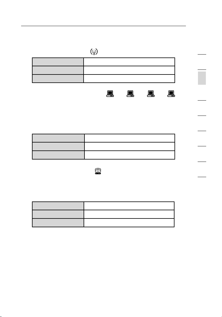
A. Wireless Network LED
OFF Wireless ne twork is OFF
Gre en Wireless ne twork is ready
Blinki ng Indica tes wireless ac tivity
B. Wired Computer Status LEDs
These LED s a re la beled 1– 4 a nd correspon d t o t he numbered
ports on t he rear of the Router. W hen a compute r i s pro perly
connec ted to one of the wi re d c omputer po rts on the rear of the
Router, t he LED will ligh t. When inf or matio n i s b eing sent ove r t he
port, the LE D blinks ra pidly.
OFF No device is linked to the po rt
Gre en 10Base -T device c on necte d
Blinki ng Port acti vity
C. Modem/WAN Status LED
This L ED ligh ts in G REEN to indica te that your m odem is
connec ted prope rl y to th e Rou te r. It b links r apidly when
inform ation i s being sent o ver the port b etween the Rou ter and
the mo dem.
OFF No WA N l ink
Solid Green Good WAN link
Blinki ng Green WAN ac tivity
1
2
3
4
5
6
7
8
9
10
sec tio n
1110
Page 15
Knowing your Router
1312
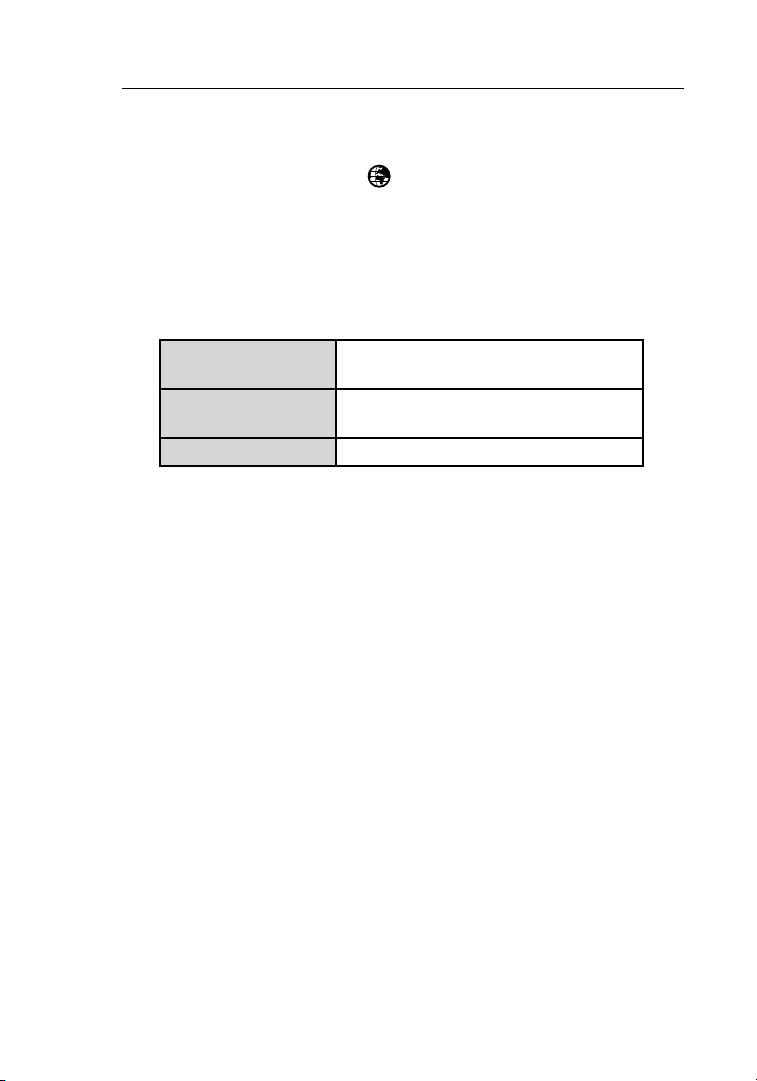
D. Internet/Connected LED
This u nique L ED show s you w hen the Router is con nected to the
Internet. W hen t he ligh t is OF F, th e Route r is NO T conne cted to
the In ter ne t. Wh en the li ght i s blink in g, th e Route r is at te mptin g
to con nect to the In ter ne t. Wh en the li ght i s solid G REEN, t he
Router is con nected to the Inter net. Wh en us in g the “ Disco nn ect
after x minut es” fea ture , thi s LED b ec omes ex tremely u seful i n
monito ring th e statu s of yo ur Rout er’s connect ion.
OFF Route r i s n ot connect ed to
the Inter net
Blinki ng Green Router is at tempt in g to connec t t o
the Inter net
Solid Green Router is co nnect ed to the Internet
Page 16

1312
Knowing your Router
E. Power/Ready LED
When y ou appl y power to the Router or resta rt it, a short p eriod
of tim e elaps es whil e the R outer b oots up . Durin g this time, t he
“Power /Ready” LED bl inks. W hen the Router has co mpletel y
booted up, th e “Powe r/Ready ” LED b ecomes a SOLID light,
indica ting th e Route r is read y for u se .
OFF Route r i s O FF
Blinki ng Green Router is bo oting up
Solid Green Router is read y
1
2
3
4
5
6
7
8
9
10
sec tio n
1312
Page 17

Knowing your Router
1514
Rear Panel
(6) (7) (8) (9)
F. Power Jack – GRAY
Connec t the i ncluded 12V/0. 5A DC p ower su pply to this j ack.
G. Connections to Computers (Wired Computer Ports) – YELLOW
Connec t your wire d (no n- wireless) comput ers to these p orts.
These ports a re R J45, 10 /100 au to-ne go tiati on , aut o- uplin ki ng
ports for sta ndard UTP c atego ry 5 or 6 Ethe rnet cable. The por ts
are labe le d 1 t hrou gh 4. T hese po rts cor re spond t o the n umbered
LEDs o n the f ro nt of t he Rout er.
H. Connection to Modem (Modem Port) – BLUE
This p ort is for con nection to you r cable or DSL modem. Use th e
cable that wa s provide d with th e mod em to c on nect th e mod em
to thi s port. Use of a cabl e other than t he cabl e suppl ied wit h the
cable modem m ay not work prop er ly.
Page 18

1514
Knowing your Router
I. Reset Button
The “R eset” b utton i s used in rare c as es wh en the Ro uter ma y
functi on improp er ly. R esett in g the R outer w ill resto re the Ro uter’s
normal operat ion whi le main taining the prog ra mmed se tting s. You
can al so restore th e facto ry defa ult set tings b y using the “R eset”
button . Use t he restore op tion in instan ces whe re you ma y have
forgotten your cu stom pa ssword.
(a) Resetting the Router
Push a nd releas e the “ Re set” bu tton. T he li gh ts on t he Ro ut er
will m omentar ily fla sh. The “Power /Ready” light will be gin to
blink. When t he “Pow er/Read y” ligh t becom es soli d again , the
res et is c omple te .
(b) Restoring the Factory Defaults
Pre ss and hold th e “ Reset ” b utton for at l ea st 10 secon ds,
then releas e i t. The ligh ts on the Router wi ll momen tarily
flash. Th e “ Power /R eady” li ght will begi n t o blink. Wh en
the “Powe r/Ready ” l ight bec omes solid ag ain, the restore
is comple te.
1
2
3
4
5
6
7
8
9
10
sec tio n
1514
Page 19

Connecting and Configuring your Router
1716
Verify the contents of your box. You should have the following:
• Belkin Wi re less G Plus MI MO Router
• Catego ry 5 N etwor ki ng Cable (f or connect ing the Rou ter to
the compu ter)
• Power Sup ply
• Belkin Ea sy Insta ll Wizard Softw are CD
• User Manu al
Modem Requirements
Your cab le or DSL modem must be equ ipped with an RJ4 5 Eth er net port .
Many modem s have both an RJ45 Eth ern et p ort and a USB conne ction.
If you have a mod em with both Ethe rne t and USB, and are u sing the
USB connec tion at this time, you will be instruct ed to use the RJ45
Ethernet po rt du ri ng th e insta ll ation p ro cedure. I f your mo dem h as only
a USB port, you ca n reques t a diffe rent type of mo dem from your I SP, or
you can, in some cas es, purchase a modem th at ha s a n R J45 Ethernet
port o n it.
Ethernet USB
Easy Install Wizard
Belkin has prov id ed ou r Easy In stall W izard sof tware to make in stallin g
your R outer a simple and ea sy task . You can u se it t o get y our Rou ter
up and runnin g in mi nutes. The Eas y Insta ll Wiza rd req uires tha t your
Window s 98SE, Me, 20 00, or XP comp uter be connec ted direc tl y to
your c able or DSL mo dem and that t he Inte rne t conne ct ion i s activ e
and wo rking a t the t ime of install ation. If it i s not, you mus t use t he
“Alter nat e Setup M ethod ” secti on of t hi s Use r Manua l to co nf igure
your R outer. Ad ditio na lly, if yo u are using an ope rating system other
than W indows 98SE, M e, 2000 , or XP, you m ust set up the Router
using the “Al ter na te Se tu p Met ho d” se ct ion o f this Us er Ma nu al.
Page 20

1716
Connecting and Configuring your Router
Step 1 Run the Easy Install Wizard Software
1
2
1 Shut down any programs that are running on your computer at
this time.
2 Make sure you have the following items at the computer that is now
directly connected to the cable or DSL modem. DO NOT CONNECT
THE ROUTER AT THIS TIME.
• T he Easy Insta ll Wizard CD-RO M
• T he Router
• T he Router Pow er Supply
• C at egory 5 Net working Ca ble
• T hi s User Manu al
3 Turn off any firewall or Internet-connection-sharing software on
your computer.
Windows User: Insert the Easy Install
Wizard software CD into your CD-ROM
drive. The Network Setup Utility screen
will automatically appear on your screen
within 15 seconds. Click on “Run the
Easy Install Wizard” to begin.
Select your region from the drop-down box shown on the screen.
Note for Windows Users: If the Easy Install
Wizard does not start up automatically, select
your CD-ROM drive from “My Computer” and
double-click on the file named “Start” to start
the Network Setup Utility.
3
4
5
6
7
8
9
10
sec tio n
1716
Page 21

Connecting and Configuring your Router
1918
Mac OS Users: Insert the Easy Install Wizard software CD into your CD-ROM
drive. Click on the CD icon; a folder will pop up. To begin, click on “start.
osx” if you have Mac OS X.
4. Follow the Easy Install Wizard to complete the installation.
Welcome Screen
After you ins ert the CD int o
your C D-ROM d rive, t he
Wizard’s welc om e screen will
appear. Make su re you ha ve not
connec ted the Router at thi s
point. If you have c onnecte d
your R outer, pl ease reco nnect
your c omputer directly t o the
modem. Click “Next” when yo u
are ready to move o n.
Progress Screen
Easy I nstall will sh ow you a
pro gress scree n each time a step
in the setup has bee n compl eted.
Each t ime you see th e progress
screen, cl ick “ Ne xt” w he n you a re
rea dy to m ove t o the n ex t ste p.
1.1 Examining Settings
The Wi zard will n ow ex am ine y ou r
comput er’s network settin gs and
gather inform ation n eeded t o
comple te the Router’s con nection
to the I ntern et. Whe n the Wizard is
finish ed exam ining y our com puter,
click “Next” to cont inue.
Page 22

1918
Connecting and Configuring your Router
1.2 Multi-NICs Screen
This s cree n wil l appea r ONLY if y ou have more than one net work
adapte r insta lled in your c omputer. If yo u have mo re than o ne netw ork
adapte r insta lled in your c omputer,
the Wi zard will n eed t o know wh ich
adapte r is co nnected to you r modem .
Select the ne twork c ard that is
connec ted to your mo dem from th e
list a nd clic k “Next ”. If y ou are no t
sure whi ch adap te r to ch oose, s elect
the ad apter a t the t op of t he list . If yo u
mistak enly ch oose th e wrong a da pter
now, yo u will be able t o cho os e a
different on e later.
Hardware Setup – Connect the Router to your
Step 2
The Wi zard will w alk y ou through connect ing you r Route r to yo ur
comput er and modem. Follow the ste ps on t he screen u sing th e
pictures a s a g ui de.
Modem and computer
2.1 This step instructs you to locate
the cable connected between your
modem and the networking port on
your computer. Unplug this cable
from the computer and plug it into
the BLUE port on the Router. Click
“Next” to continue.
1
2
3
4
5
6
7
8
9
10
sec tio n
1918
Page 23

Connecting and Configuring your Router
2120
2.2 This step instructs you to locate
the YELLOW cable that is included
with your Router. Plug one end
of this cable into ANY one of the
YELLOW ports on your Router.
Plug the other end of the cable
into the networking port on your
computer. Click “Next” to continue.
2.3 This step instructs you to locate
the power supply that is included
with your Router. Plug the power
supply’s small connector into the
GRAY port on the Router. Plug the
power supply into an empty power
outlet. Click “Next” to continue.
2.4 This step instructs you to look at
the lights on the front of your
Router. Make sure the appropriate
lights are ON. Refer to the Easy
Install Wizard software on your
computer’s screen for more details.
Click “Next” to continue.
Page 24

2120
Connecting and Configuring your Router
Step 3 Checking the Connection
1
2
3.1 Once you have completed
connecting the Router, the Wizard
will check the connection to the
Router then go on to determine
what type of Internet connection
you have.
3.2 User Name and Password Needed
If you have a connec tion ty pe that req uires a u ser nam e and a
passwo rd , the W iz ard will ask you to typ e in yo ur user name a nd
passwo rd . If yo ur conn ec tion ty pe do es not requ ire a use r name and
passwo rd , you w il l not s ee th is screen.
Your user name and password is
provided to you by your Internet
Service Provider. If you have to
type in a user name and password
to connect to the Inter net, then
type that same user name and
password in here. Your user
name looks something like
“jsmith@myisp.com” or simply
“jsmith”. The service name is
optional and is very rarely required
by your ISP. If you don’t know your
service name, leave this blank.
When you have entered your
information, click “Next” to
move on.
3
4
5
6
7
8
9
10
sec tio n
2120
Page 25

Connecting and Configuring your Router
2322
3.3 Wireless Setup
Thi s Ste p Is Op ti onal. C lick
“Next” if you want t o skip it.
Usi ng th is step , you c an
custom ize you r wireles s netwo rk
settin gs if y ou want to. Fo llow
the st eps on the scree n to
comple te this step. Click “ Next”
to con tinue.
Step 4 Configuring the Router
The Wi zard will n ow tr an sfer al l of th e con fi gurat io n inf or matio n to th e
Router. This wi ll ta ke approxim ately o ne minu te. Dur ing thi s time, do
not tu rn off the Rou ter or compute r. The Ro uter wi ll restar t itsel f at th e
end of this s tep.
4.1 Checking Internet
The Wiza rd w ill now check for
an Int ern et conn ec tion. T his c an
take a few mi nutes. The Wiz ard
may no t detec t a con nection right
away. If no t, it w ill retry a numb er
of tim es. The “Conne cted” l ight on
the fron t panel o f the R outer w ill
flash during this ti me. Ple ase be
patien t through t his p roce ss.
Page 26

2322
Connecting and Configuring your Router
4.2 Finished
Whe n the I nternet co nnectio n
is com plete, the Wiz ard will te ll
you th at you are finis he d. Th e
“Conne cted” L ED on t he front of
the Ro uter wi ll be s olid GR EEN,
indica ting th at the Router is now
connec ted to the Int ern et .
Your R ou ter i s now c on necte d to th e Inter net. Now you can be gin
surfin g the I ntern et by o penin g your brow ser and going to your favori te
web pa ge.
Congra tulatio ns! You hav e finis hed ins talling your n ew Belk in Rout er.
You are ready to set up the ot her com puters in your home. You can
also a dd comp uters t o your Router any tim e you w ant.
1
2
3
4
5
6
7
8
9
10
sec tio n
2322
Page 27

Alternate Setup Method
2524
Step 1 Connecting your Gateway Router
1.1 Turn off the power to your modem by unplugging the power supply
from the modem.
1.2 Locate the network cable that is connected between your modem
and your computer and unplug it from your computer, leaving the
other end connected to your modem.
1.3 Plug the loose end of the cable you just unplugged into the port on
the back of the Router labeled “Internet/WAN”.
1.4 Connect a new network cable (not included) from the back of the
computer to one of the ports labeled “1–4”. Note: It does not matter
which numbered port you choose.
1.5 Turn your cable or DSL modem on by reconnecting the power
supply to the modem.
1.6 Before plugging the power cord into the Router, plug the cord into
the wall, then plug the cord into the Router’s power jack.
Mac or PC computer that was originally
connected to the cable or DSL modem
To Power Adapter
Network cable
(to computer)
Existing networking cable
(came with modem)
Page 28

2524
Alternate Setup Method
1.7 Verify that your modem is connected to the Router by checking
the lights on the TOP of the Router. The green light labeled “WAN”
should be ON if your modem is connected correctly to the Router. If
it is not, recheck your connections.
1.8 Verify that your computer is connected properly to the Router
by checking the lights labeled “LAN 1,2,3,4”. The light which
corresponds to the numbered port connected to your computer
should be ON, if your computer is connected properly. If it is not,
recheck your connections.
Step 2: Step 2: Set your Computer’s Network Settings to
Work with a DHCP Server
See th e secti on in t his Use r Manua l calle d “Manu ally Co nfiguri ng
Networ k Setti ngs” fo r directi on s.
Step 3: Configuring the Router Using the Web-Based
Advanced User Interface
1
2
3
4
sec tio n
5
6
7
8
9
10
Using your In ter ne t browser, you c an acce ss the Ro uter’s Web-Ba sed
Advanc ed User Interf ace. In your b ro ws er, typ e “192. 168.2.1 ” (do
not ty pe in a nything else s uch as “http:/ /” or “ www”). Then pres s the
“Enter ” key.
2524
Page 29
Alternate Setup Method
2726
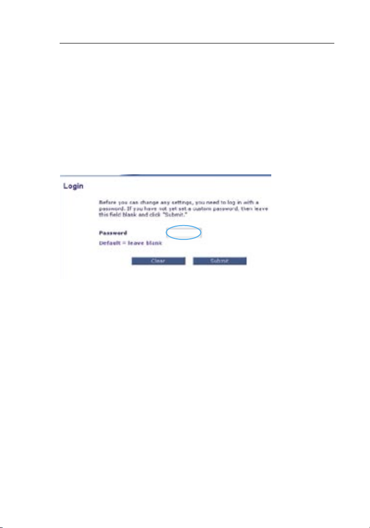
Logging into the Router
You will s ee the Router’s hom e page in your browser window. Th e
home p age is visible to any user w ho want s to se e it. To ma ke any
change s to th e Route r’s s ettings , you h ave to log in. Clicki ng the
“Login ” butto n or cl icking on any one of the lin ks on t he home page
will t ake you to the login scre en. T he Rout er ship s with no pass wo rd
entered. I n the l ogin sc re en, lea ve the password blank a nd clic k the
“Submi t” butt on to l og in.
Logging out of the Router
One co mputer at a ti me can log int o the R outer f or the purpose s
of mak ing cha nges to the se ttings of the Router. O nce a u ser h as
logged in to make ch anges, there are two ways t hat the comput er
can be logged out. C licking the “L ogout” button will lo g the c omputer
out. T he seco nd meth od is a utomati c. The login w ill tim e out a fter a
specif ied per iod of time. T he defa ult log in time -out is 10 min utes. T his
can be change d from on e to 99 m inute s. For mo re inform ation, see the
sectio n in th is manu al titl ed “Cha nging t he Logi n Time- Out Set ting”.
Understanding the Web-Based Advanced User Interface
The ho me page is the first page yo u will see whe n you a ccess t he
Advanc ed User Interf ace (UI ). The home pa ge show s you a quick view
of the Router ’s st atus an d setti ngs. Al l advan ced set up page s can b e
rea ched from this p age.
Page 30

2726
Alternate Setup Method
(10) (2) (5) (4) (3)
(1)
(9)
1. Quick-Navigation Links
You can go directly to any of the Router ’s ad vanced UI page s by
clicki ng direct ly on t he se li nk s. Th e links a re divide d into logical
catego ries an d grouped b y tab s to ma ke find in g a p ar ticul ar
settin g easie r to fi nd. Cli cking o n the p urple h eader o f each tab
will s how you a shor t descr iption of the tab’s functi on.
(8)
(7)
(6)
1
2
3
4
sec tio n
5
6
7
8
9
10
2. Home Button
The ho me butt on is a vailabl e in ev ery pag e of th e UI. P re ss ing t hi s
button will t ake you back t o the h ome pag e.
3. Internet Status Indicator
This i ndicato r is vi sible i n all p ages of the Ro uter, i nd icati ng
the co nnectio n statu s of th e Route r. When t he in di cator s ays
“Conne ction O K” in G REEN, t he Rout er is c onnecte d to th e
Internet. W hen t he Rout er is n ot conn ec ted t o the I nt ern et, the
indica tor wil l re ad “n o conne ct ion” in RED. T he in di cator i s
automa tically update d when you mak e chang es to t he sett ings of
the Ro uter.
2726
Page 31

Alternate Setup Method
2928
(10) (2) (5) (4) (3)
(1)
(6)
(9)
(8)
(7)
4. Login/Logout Button
This b utton e nables you to log in and out of the Router with t he
pre ss of o ne bu tt on. W he n you a re logged into t he Rout er, thi s
button will c hange t o re ad “L og out”. L oggin g into th e Rou te r wil l
take y ou to a separa te logi n page where you w ill n ee d to en ter a
passwo rd . When yo u are log ged in to the Router, you ca n make
change s to th e setti ngs. Wh en you are finis he d mak in g cha ng es,
you ca n log o ut of t he Rout er by c licking the “L ogout” button. For
more inf or matio n about l oggin g into th e Rou te r, see the sec tion
called “Loggi ng into the Ro uter”.
5. Help Button
The “H elp” bu tton gi ves you access to the Router ’s he lp page s.
Help i s also availab le on m any pag es by c licking “more in fo ” nex t
to cer tain se ctions of each page.
Page 32

2928
Alternate Setup Method
6. LAN Settings
Shows you the settin gs of t he Loca l Area Ne tw ork ( LA N) si de of
the Ro uter. C ha nges ca n be ma de to t he se tt ings by clic ki ng on
any on e of th e links (IP Ad dres s, Su bn et Ma sk , DHC P Serve r)
or by clickin g the “ LAN” Qu ick Nav igation link o n the l eft sid e
of the screen.
7. Features
Shows the sta tus of the Rou ter’s NAT, firewall, and wi re less
features . Chang es can be made t o the s ettin gs by c li cking o n any
one of the li nks or by clic king th e “Quic k Navig ation” links o n the
left s ide of the scree n.
8. Internet Settings
Shows the set tings o f the I ntern et/WAN si de of t he Rout er that
connec ts to t he Inte rne t. Chan ge s to an y of th ese s et tings c an be
made b y click ing on the lin ks or b y click ing on the “In ter ne t/WA N”
Quick Navigat ion lin k on th e left side of the sc re en .
9. Version Info
Shows the fir mware ver si on, b oo t-cod e versi on , hardware version ,
and se rial nu mber of the Ro uter.
10. Page Name
The pa ge you are on ca n be id en tifie d by th is name . This ma nual
will s ometime s re fer t o pages b y nam e. For in stanc e “LAN > LAN
Settin gs” refer s to th e “LAN Se tting s” page .
1
2
3
4
sec tio n
5
6
7
8
9
10
2928
Page 33

Alternate Setup Method
3130
Configuring your Router for Connection to your
Step 4
The “I ntern et/WAN” t ab is w he re you wi ll set up your Router to
connec t to yo ur Inte rne t Servi ce Provider (ISP). The Ro uter is capabl e
of con necting to vir tually any ISP ’s sy stem prov id ed yo u have co rrectly
config ured the Ro uter’s set ti ngs f or your I SP’s conne ction t ype. Your
ISP co nnectio n setti ngs are p rovi ded to you by your IS P. To confi gure
the Ro uter wi th the setting s that your IS P gave you, cl ick “Co nnectio n
Type” (A) on the le ft si de of t he screen. Select the con nection type y ou
use. I f your ISP gav e you D NS sett ings, c licking “DNS” (B) allow s you
to ent er DNS address e nt ries fo r ISP s that requ ire speci fic set tings.
Clicki ng “MAC Address” (C) will let yo u clone your c omputer ’s MA C
address or type i n a s pe cific WAN M AC ad dres s, if req uire d by yo ur
ISP. W hen you have f inished making settin gs, the “Inter net S tatus ”
indica tor wil l re ad “C on necti on OK” if your R outer i s set u p properl y.
Internet Service Provider (ISP)
(A)
(B)
(C)
Page 34

3130
Alternate Setup Method
Setting your Connection Type
Fro m the “Con nection Type” page, you can select the type of co nnectio n
you use. S el ect the typ e of c onnecti on you use by cli cking the b utton
(1) next to you r conne ction t ype and then c licking “Next” (2).
(1)
1
2
3
4
sec tio n
5
6
7
8
(2)
9
10
3130
Page 35

Alternate Setup Method
3332
Setting your Internet Service Provider (ISP) Connection Type
to Dynamic IP
A dyna mic con nection type i s the m ost com mon con nection type
found with ca ble mod ems. Se tting t he conn ection type to “dynam ic” in
many c ases is enough to com plete t he conn ection to your ISP. S ome
dynami c conne ction t ypes ma y re quire a h ost nam e. You can enter
your h ost nam e in th e space pro vided i f you w ere assig ned one . Your
host n ame is assigne d by yo ur ISP. Some d ynamic connect ions ma y
req uire that you cl one the MAC ad dress of the PC that wa s origi nally
connec ted to the mod em.
1. Host Name
This s pace is pro vided t o ent er a ho st name t hat n ee ds to b e
visibl e to yo ur ISP. Enter your ho st name here and click “Apply
Change s” (3). I f your ISP did not as sign yo u a hos t name, or you
are not su re , leave this b lank.
2. Change WAN MAC Address
If you r ISP req ui re s a spe cific M AC addres s to co nnect t o the
servic e, you can ent er a sp ecific MAC add re ss or c lo ne th e
current co mpute r’s M AC address through t his lin k.
(1)
(2)
(3)
Page 36

3332
Alternate Setup Method
Setting your Internet Service Provider (ISP) Connection Type
to Static IP
A stat ic IP a ddre ss co nn ectio n type is less c ommon t han o th er
connec tion ty pes. If your I SP uses static IP add re ss ing, yo u wil l
need y our IP address, su bnet ma sk, a nd ISP ga teway a ddress. T his
inform ation i s avail able from y our I SP or o n the p ap erwor k that yo ur
ISP le ft with you. Type in your inform ation, then cl ick “Ap ply Cha nges”
(3). Aft er you apply t he chan ges, th e Inter net Status indica tor wil l re ad
“Conne ction O K” if y our Rou ter is set up prop erly.
1. IP Address
Pro vided b y you r ISP. En ter you r IP ad dress here.
2. Subnet Mask
Pro vided b y you r ISP. En ter you r subne t mask here.
3. ISP Gateway Address
Pro vided b y you r ISP. En ter the ISP ga teway a ddress he re.
4. My ISP Provides More Than One Static IP Address
If you r ISP a ssigns you more th an on e stati c IP ad dres s, your
Router is cap able of handli ng up t o five static WAN IP addres se s.
Select “My IS P provide s more than one st atic IP address” and
enter your ad ditiona l address es .
(1)
1
2
3
4
sec tio n
5
6
7
8
9
10
(2)
(3
(4)
)
3332
Page 37

Alternate Setup Method
3534
Setting your ISP Connection Type to PPPoE
Most DSL provi de rs use PPPo E as the connect io n type . If yo u use a
DSL mo dem to co nnect t o the I nt ern et, you r ISP may use PP PoE to lo g
you into t he s ervice. I f you have an Int ern et c onnec ti on in your ho me or
small offi ce th at does n’t re quire a mod em, you may al so use PPPoE.
(1)
(2)
(3)
(4)
(5)
Your connection type is PPPoE if:
1. Your ISP gave you a user name and password which is required to
connect to the Internet
2. Your ISP gave you software such as WinPOET or Enternet300 that
you use to connect to the Internet
3. You have to double-click on a desktop Icon other than your browser
to get on the Internet
Page 38

3534
Alternate Setup Method
1. User Name
This s pace is pro vided t o typ e in yo ur User n ame t ha t was
assign ed by y our ISP.
2. Password
Type in yo ur pass word and re-t ype it into th e “Rety pe Pass word”
box to confir m it.
3. Service Name
A Serv ice nam e is ra re ly required b y an IS P. If y ou are not sure if
your I SP requires a servic e name, leave this bl ank.
4. MTU
The MT U setti ng shou ld neve r be ch anged u nless y our ISP gives
you a specifi c MTU s etting. Making change s to th e MTU s etting
can ca use probl em s wit h your In ter net con nection includ ing
discon nection fro m the I nternet, s low Int ern et acce ss and
pro blems w ith I nt ern et appl ication s worki ng proper ly.
5. Disconnect after X…
The Di sconnec t featu re i s use d to au to matic al ly di sc onnec t the
rou ter f rom your IS P when there is no acti vity fo r a spe cified
period of tim e. For instanc e, plac ing a c heck ma rk next to thi s
option and en tering 5 into the min ute fie ld will cause the route r to
discon nect from t he Inte rne t after 5 minute s of no I nternet ac tivity.
This o ption s hould b e used if you pay for your I ntern et se rv ice b y
the mi nute.
1
2
3
4
sec tio n
5
6
7
8
9
10
3534
Page 39

Alternate Setup Method
3736
Setting your Internet Service Provider (ISP) Connection Type to
Point-to-Point Tunneling Protocol (PPTP)
[Europea n Count ri es On ly ]. So me ISPs req uire a co nnectio n using
PPTP p ro to col, a type of conn ec tion mo st co mm on in E uropean
countr ies. Th is sets up a d irec t con ne ction t o the I SP’s syste m. Type in
the in formati on provid ed by y ou r ISP i n the s pace prov ided. W hen you
have f inished , click “Apply Change s” (9). A fter yo u apply the ch anges,
the In ter ne t Sta tu s ind ic ator wi ll read “ Connect ion OK” if you r Route r
is set up prope rl y.
(1)
(2)
(3)
(4)
(5)
(6)
(7)
(8)
1. PPTP Account
Pro vided b y you r ISP. En ter you r PPTP account name h ere.
2. PPTP Password
Type in yo ur pass word and rety pe it i nto the “Retyp e Passw ord”
box to confir m it.
3. Host Name
Pro vided b y you r ISP. En ter you r host name he re .
4. Service IP Address
Pro vided b y you r ISP. En ter you r servi ce IP a ddress he re.
Page 40

3736
Alternate Setup Method
5. My IP Address
Pro vided b y you r ISP. En ter the IP add re ss here.
6 My Subnet Mask
Pro vided b y you r ISP. En ter the IP add re ss here.
7. Connection ID (optional)
Pro vided b y you r ISP. If your I SP did not giv e you a connec tion ID ,
leave this bl ank.
8. Disconnect after X…
The Di sconnec t featu re i s use d to au to matic al ly di sc onnec t the
Router fro m you r ISP w he n the re i s no ac tivity for a s pecifie d
period of tim e. For instanc e, plac ing a c heck ma rk next to thi s
option and en tering “5” int o the m inute f ield wi ll caus e the R outer
to dis connect fro m the I nternet af ter fiv e minut es of n o Inter net
activi ty. T his opt ion sho uld be used if you pa y for y our Int ern et
servic e by th e minut e.
1
2
3
4
sec tio n
5
6
7
8
9
10
3736
Page 41

Alternate Setup Method
3938
Setting your Connection Type if You Are a Telstra® BigPond User
Your user name an d passw ord are provide d to yo u by Telstr a BigPo nd.
Enter this in formati on belo w. Choos in g you r state f ro m the d ro p-down
menu (6) will a utomatica lly fil l in yo ur logi n serve r IP ad dres s. If y our
login server address i s different t han one pro vided h ere, you may
manual ly ente r the l ogin se rver IP address by plac in g a c he ck in t he
box ne xt to “ User De cide Lo gin Ser ver Man ually” (4) and t ype in the
address ne xt to “ Login S erver ” (5). Wh en you have entered a ll of y our
inform ation, click “ Apply C hanges” (7). Aft er you apply t he chan ges,
the In ter ne t Sta tu s ind ic ator wi ll read “ Connect ion OK” if you r Route r
is set up prope rl y.
(1)
(2)
(3)
(4)
(5)
(7)
1. Select your State
Select your s tate from t he drop-d own men u (6). Th e “Lo gi n
Server ” box w ill aut omatica lly be filled in with an IP address. If for
some reaso n this address d oe s not m atch th e address t hat Telstra
has gi ven, yo u can m anually enter the log in serv er addres s. See
“User Decide Login S erver M anually ” (4).
2. User Name
Pro vided b y you r ISP. Type i n your user na me here.
(6)
Page 42

3938
Alternate Setup Method
3. Password
Type in yo ur pass word and rety pe it i nto the “Retyp e Passw ord”
box to confir m it.
4. User Decide Login Server Manually
If you r login server IP add re ss is n ot avai la ble i n the “ Se lect Your
State” dro p-dow n menu (6), you may man ually e nter th e login
server IP add re ss by p la cing a check i n the b ox ne xt to “ Us er
Decide Login Server Manuall y” and type in the ad dres s nex t to
“Login Server ” (5).
Setting Custom Domain Name Server (DNS) Settings
A “Dom ain Nam e Serve r” is a server locate d on th e Inter net t hat
transl ates Un iversal Resource L ocato rs (URL s) like “ www.belk in.com”
to IP addresses . Many In ter net Ser vice Prov id ers ( IS Ps) d o not requi re
you to enter this in formati on into the Ro uter. T he “Aut om atic from ISP”
box (1) should be chec ked if your IS P did n ot give you a specifi c DNS
address. I f you a re using a stati c IP co nnectio n type, then y ou may
need t o enter a spec ific DN S address a nd se co ndary D NS ad dres s for
your c onnecti on to w ork prope rl y. If your c onnec ti on ty pe is d yn amic
or PPP oE, it is like ly that you do not ha ve to e nter a DNS add re ss .
Leave the “Au tomatic fro m ISP ” box c he cked. To enter t he DNS
address se tting s, unch ec k the “ Autom at ic from I SP” box and en ter
your D NS entr ies in the spa ces provi de d. Cl ic k “Ap pl y Cha ng es” (2)
to sav e the s ettings .
1
2
3
4
sec tio n
5
6
7
8
9
10
(1)
(2)
3938
Page 43

Alternate Setup Method
4140
Configuring your WAN Media Access Controller
(MAC) Address
All ne twork c omponen ts incl uding c ards , ada pt ers, an d routers , have
a uniq ue “ser ial num ber” ca lled a MAC add re ss . Your In terne t Servi ce
Pro vider ( ISP) ma y record th e MAC a ddre ss of y our com puter’s
adapte r and o nly let that p articul ar comp uter co nnect t o the I ntern et
servic e. When you in stall t he Rout er, its o wn MA C address w ill be
“seen” by the ISP an d may c ause th e conne ction n ot to w ork. Be lkin
has prov id ed th e abili ty to c lo ne (c op y) th e MAC a dd re ss of t he
comput er into the Ro uter. T hi s MAC a ddress, i n tur n, wi ll be s ee n
by the ISP’s syste m as th e origi nal MAC address an d wil l allow t he
connec tion to work. If you are not s ure whether your I SP need s to
see th e origi nal MAC address, s imply c lone th e MAC a ddress of the
comput er that was or iginall y conne cted to the mo dem. Cl oning t he
address wi ll no t cause a ny proble ms with your n etwork.
Page 44

4140
Alternate Setup Method
Cloning your MAC Address
To clone y our MAC address, make s ure that yo u are usi ng the
comput er that was OR IGINALLY CO NNECTED to you r modem before
the Ro uter wa s insta lled. C lick th e “Clon e” butt on (1). C lick “A pply
Change s” (3). You r MAC a dd re ss is n ow clon ed to t he Rout er.
Entering a Specific MAC Address
In cer tain ci rc um stanc es you ma y nee d a spe ci fic WAN M AC address.
You can ma nually enter o ne in t he “MAC Address” page. Type in a
MAC ad dres s in th e spa ce s provide d (2) and cl ick “ Ap ply C ha nges”
(3) to s ave the change s. The Router’s WAN M AC address will no w be
change d to th e MAC a ddre ss yo u speci fi ed
(2)
(1)
(3)
1
2
3
4
sec tio n
5
6
7
8
9
10
4140
Page 45

Using the Web-Based Advanced User Interface
4342
Using your In ter ne t browser, you c an acce ss the Ro uter’s Web-Ba sed
Advanc ed User Interf ace. In your b ro ws er, typ e “192. 168.2.1 ” (do
not ty pe in a nything else s uch as “http:/ /” or “ www”) t hen press t he
“Enter ” key.
You will s ee the Router’s hom e page in your browser window.
Viewing the LAN Settings
Clicki ng on t he head er of t he LAN tab (1) w ill tak e you t o the L AN tab’s
header page. A quick descri ption o f the f unction s can b e found here.
To view th e setti ngs or make ch anges t o any o f the L AN sett ings, c lick
on “LA N Setti ngs” (2) or to v iew the list o f conne cted co mputers , click
on “DH CP clie nt list ” (3).
(1)
(2)
(3)
Page 46

4342
Using the Web-Based Advanced User Interface
Changing LAN Settings
All se ttings for the internal LA N set up of t he Rout er can be view ed and
change d here.
(1)
(2)
(3)
(4)
(5)
(6)
1. IP Address
The “I P address ” is th e inter nal I P address o f the R outer. The
defaul t IP ad dres s is “1 92.16 8. 2.1”. To access the adv anced
setup interfa ce, typ e this IP addres s into th e add ress bar of your
bro wser. T his add re ss can be chan ged if needed. To change the
IP add ress , type in the ne w IP ad dres s and c lick “A pply Ch an ges”.
The IP address yo u cho os e sho ul d be a non-routa ble IP. Exampl es
of a n on-routab le IP a re:
192.16 8.x.x ( where x i s anyth in g bet we en 0 an d 255 )
10.x.x .x (whe re x is a ny thing b etwee n 0 and 2 55)
1
2
3
4
5
sec tio n
6
7
8
9
10
2. Subnet Mask
There is n o nee d to ch an ge th e subne t mask. T his i s a uni qu e,
advanc ed feat ure of yo ur Belk in Rout er. It is possib le to c hange
the su bnet ma sk if n ecessar y; howe ver, do N OT ma ke chan ge s to
the su bnet ma sk unle ss you have a specifi c re ason to do s o. The
defaul t setti ng is “ 255.255 .255.0” .
4342
Page 47

Using the Web-Based Advanced User Interface
4544
3. DHCP Server
The DH CP serv er func tion ma kes set ting up a netw ork ver y easy
by ass igning IP addres se s to ea ch co mp uter on the ne twork
automa tically. The defaul t setti ng is “ On”. Th e DHCP server
can be turn ed OF F if ne ce ssary ; howev er, in orde r to do s o you
must m anually set a static IP addres s for e ac h com pu ter o n
your n etwork. To tur n off the D HCP ser ver, se lect “O ff” and cli ck
“Apply Change s”.
4. IP Pool
The ra nge of IP addres se s set a side fo r dyn am ic as si gnmen t
to the comput ers on your ne twork. The def ault is 2–100 (99
comput ers). I f you w ant to change this nu mber, y ou can do so
by ent ering a new st arting and end ing IP address a nd clic ki ng on
“Apply Change s”. The DHCP s erver c an assi gn 100 IP addres se s
automa tically. Thi s means that y ou cann ot spec ify an IP addres s
pool l arge r than 100 com puters. For ex ample, startin g at 50
means you hav e to en d at 15 0 or lo wer so as not to exce ed the
100-cl ient li mit. Th e start ing IP address m us t be lo wer i n numbe r
than t he endi ng IP a ddre ss.
5. Lease Time
The le ngth of time t he DHCP server will res er ve th e IP ad dres s
for ea ch comp uter. We rec om mend th at yo u leave t he le as e tim e
set to “Forever ”. The de fault s ettin g is “F orev er”, me aning t hat
any ti me a co mputer is assi gned an IP add re ss by t he DHCP
server, the I P address w ill not change for th at part icular compute r.
Settin g lease times for sho rter in tervals such a s one d ay or o ne
hour f re es IP a dd re sses af ter the specif ied per iod of time. T his
also m eans th at a pa rticula r compu ter’s IP add re ss may ch ange
over t ime. If you ha ve set any of the oth er adva nced fe atures of
the Ro uter su ch as D MZ or c lient I P filte rs, the se are de pe ndent
on the IP add re ss . For t his reaso n, you will no t want the IP
address to chan ge .
6. Local Domain Name
The de fault s etting is “Bel kin”. You c an set a local domain name
(netwo rk name ) for y our net work. T here is n o need to chan ge
this s etting unless you hav e a spe cific a dvanced need t o do so .
You can na me the network anythi ng you want su ch as
“MY NE TWORK”.
Page 48

4544
Using the Web-Based Advanced User Interface
Viewing the DHCP Client List Page
You can vi ew a li st of t he comp uters ( known a s clien ts), wh ich are
connec ted to your ne twork. You are able to view the IP address (1) of
the co mputer, t he ho st name (2) (if the com puter h as been assign ed
one), and the MAC ad dres s (3) o f the c omputer ’s ne twork i nterfac e
card (NI C) . Pressin g the “ Refresh” (4) butto n will update the lis t. If
there ha ve been a ny ch an ges, th e lis t will be upda te d.
(1) (2) (3)
(4)
1
2
3
4
5
sec tio n
6
7
8
9
10
4544
Page 49

Using the Web-Based Advanced User Interface
4746
Configuring the Wireless Network Settings
The “W irel ess” ta b let s you m ak e cha ng es to t he wi rele ss netw ork
settin gs. From th is ta b you c an make c hange s to th e wireless network
name ( SSID), operati ng chan nel, en cryptio n secur ity set tings, and
config ure the R ou ter t o be us ed as a n Acces s Point .
Changing the Wireless Network Name (SSID)
To identif y your wireless network , a nam e calle d the S SID (Se rvice
Set Id entifie r) is u sed. Th e SSID is your networ k name. The de fault
networ k name of the Router is “Bel kin G P lus MIM O_” fol lowed b y
six di gits th at are un iq ue to y our R ou ter. Your n etwork name wi ll look
someth ing lik e “Belk in G Pl us MIMO _012345 ”. You can change this to
anythi ng you choose, or you can le ave it unchang ed. Kee p in mi nd, if
you de cide to change your w irel ess n et work na me, a nd there are other
wireless n etwor ks oper at ing i n your area , your network name n eeds to
be diffe rent from oth er wireless networ ks that may be operat ing in your
are a. To cha nge the SSID, type in the SS ID that you wa nt to u se in t he
SSID f ield (1) and cli ck “App ly Chan ges” (2). The ch ange is imme di ate.
If you make a change to the SSID, your wi re le ss-eq ui pped co mpute rs
may al so need to be re co nfigu red to conn ect to your ne w netwo rk
name. Refer t o the d ocument ation o f your wire less ne twork a dapte r for
inform ation o n makin g this change.
(1)
(2)
Page 50

4746
Using the Web-Based Advanced User Interface
Using the Wireless Mode Switch
This s witch a llows y ou to s et the Router’s wirel es s mod es . The re a re
three mo de s.
802.11g-Only Mode
Settin g the R outer t o this mode wi ll allo w only G Plus MIMO an d
802.11 g-compl iant de vices t o join the net work, k eeping out any
slower 802.11 b devic es.
802.11g & 802.11b
Settin g the R outer t o this mode wi ll let G Plus MIMO-, 802.11g -, and
802.11 b-compl iant de vices t o join the net work.
Off
This m ode wil l tur n OFF t he Ro ut er’s Acces s Point , so no w ireless
device s can j oin the networ k. Turning o ff t he wi rele ss func tion of your
Router is a g re at way to secu re y our net work wh en you are away
fro m hom e for a l ong p er iod o f time, o r don ’t w ant to use the wireless
feature of the Ro uter at a ce rt ain t im e.
1
2
3
4
5
sec tio n
6
7
8
9
10
4746
Page 51

Using the Web-Based Advanced User Interface
4948
Changing the Wireless Channel
There are a number of oper ating c hannels you ca n choos e from. I n the
United States , there a re 1 1 chann els. In the Un ited Ki ngdom a nd most
of Europ e, there are 13 chan nels. I n a sma ll numb er of o ther co untries ,
there are ot her cha nnel requ irem ents. Your Router is conf igured to
operat e on th e proper ch annel s for t he coun tr y you res ide in. The
channe l can b e chang ed if n eeded. If there are other w ireless n etworks
operat ing in your area , your ne twork s hould b e set t o ope ra te on a
channe l that is different than th e other wireless networ ks.
Auto Channel Selection Feature and Changing the Channel
For be st perf ormance , your Router should use a c hannel that is at
least five ch annels away from t he ot he r wireles s netwo rks in the area.
For in stance, if ano ther ne twork i s opera ting on channe l 11, t hen set
your n etwork to chan nel 6 o r below. T he au to chan ne l sel ec tion mo de
will c hoose t he clea re st chan ne l to op erate o n whe n the R ou ter i s first
powered up . Your Ro uter sh ips from th e facto ry with the au to chan nel
feature en abled . You can m anually select a chan nel if you wis h;
howeve r, it i s re commend ed to u se the auto ch annel m ode. To cha nge
the ch annel, select the cha nnel from t he drop-d own lis t. Clic k “Appl y
Change s”. The change is imm ediate.
Page 52

4948
Using the Web-Based Advanced User Interface
Using the Broadcast SSID Feature
Note: This ad vanced feature s ho uld b e emplo ye d by ad vance d
users only. Fo r secur it y, you can choose not to bro adcast your
networ k’s S SID. Do ing so will ke ep your networ k name hidden from
comput ers tha t are sca nn ing f or the pres ence of wireless networ ks. To
turn off the broa dcast o f the S SID, remo ve the check m ark from the
box ne xt to “ Broa dcast S SID”, a nd th en clic k “Appl y Chang es ”. Th e
change is imm ediate. Each c omputer now ne eds to be set to conn ect
to you r speci fic SSI D; an S SID of “ANY” w ill no longer be acce pted.
Refer to the documen tation of your wireless n etwor k adapt er for
inform ation o n makin g this change.
Protected Mode Switch
Pro tecte d mode wi ll en su re proper o peratio n of 80 2.11g d evices on
your G Plus M IMO net work wh en 802. 11b dev ices are pres ent or when
there is h eavy 80 2.11b t raffic in the op erating environm ent. If you are
using a mix o f Belki n G Plu s MIMO Wire less Ca rd s and 8 02.11b or
802.11 g cards on your ne tw ork, prot ected m od e shoul d be us ed . If yo u
are in a n environme nt where there is no other (or ver y littl e) 802. 11b
wireless n etwor k traffic, best 80 2.11g p erforma nce may be ach ieved
with p ro te cted mo de OF F. If you are op erati ng in a n environme nt with
HEAVY 8 02.11b traffic o r inter fere nce, be st 80 2. 11g p er forma nc e
may be achiev ed with pro tecte d mode ON . Wireles s G Plu s MIMO
perfor mance i s not a ff ec ted b y this se tting .
Changing the Wireless Security Settings
Your Route r is eq uipped with th e lates t secur ity sta ndard cal led
Wi-Fi Prot ected A ccess ( WPA). It a ls o sup po rts t he lega cy secu ri ty
standa rd c alled W ired Equi valent Privacy (WEP). By def ault, w ireless
securi ty is d isabled . To enable securi ty, y ou will need t o deter mine
which standard yo u wan t to us e. To acces s the s ecurity settin gs, cli ck
“Secur ity” on the “W irel ess” ta b.
1
2
3
4
5
sec tio n
6
7
8
9
10
4948
Page 53

Using the Web-Based Advanced User Interface
5150
The Ro uter fe atures WPA2, w hi ch is t he se co nd ge ne ratio n of th e
WPA- based 8 02.11i standard. I t offers a highe r level of wirel ess
securi ty by c ombinin g advan ced net work au thentic ation a nd strong er
Advanc ed Encr yption Standard (A ES) e nc rypti on meth od s.
WPA2 Requirements
IMPORTAN T: In ord er to u se WPA2 secu rity, all yo ur co mp uters
and wi re le ss cl ie nt ad ap ters mu st be u pgrad ed with p atche s, driv er,
and cl ient ut ility s oftware t ha t sup po rted WPA2. A t the t ime o f this
User M anual’s publ ication , a cou ple sec urity p atches are avail ab le,
for free d ownlo ad , from Mi crosoft®. Thes e patch es work only w ith
the Wi ndows X P opera ting sy stem. O ther op erating system s are not
suppor ted at this ti me.
For Wi ndows X P compu ters th at do n ot have Servic e Pack 2
(SP2), a file fro m Mic roso ft call ed “Win dows XP Suppor t Patch
for Wi re le ss Protec ted Acc ess (KB 826942 )” is a vailabl e for f re e
downlo ad at h ttp://s upport. microsoft .c om/?k bi d=826 94 2
For Wi ndows X P with Service Pack 2 , Microso ft has rele ased a
fre e dow nl oad t o updat e the w irel ess cli ent com ponents to sup port
WPA2 (KB893 357). T he upda te is a vailabl e from:
http:/ /suppor t.microso ft .com/ de fault .a spx?s ci d=kb; en -us;8 93 357
IMPORTAN T: You al so need to ens ure that al l your wireless client
cards/ad ap ters su pport W PA2 , and t ha t you h ave d ow nload ed and
instal led the latest driver. Most of the Be lkin wi re less ca rd s have driver
update s avail able fo r downl oad from th e Bel ki n sup po rt si te :
www.bel ki n.com /n etwor ki ng.
Setting WPA/WPA2-Personal (PSK)
Like W PA se curity, WPA2 is a vailabl e in bo th WPA2-Pers onal (P SK)
mode a nd WPA2-Ente rprise (RADIUS ) mode. Typically, WPA2-Pers onal
(PSK) is the mode th at will be use d in a home en viro nment , while
WPA2 -Enterp rise (R ADIUS) is impl emented in a b usiness environm en t
where an e xternal ra dius se rver di stribut es the network key to the
client s autom aticall y. Th is guid e will focus o n WPA2-Perso nal (PS K)
usage. Please ref er to t he Us er Manu al for mo re inform ation a bout
wireless s ecuri ty and di ff erent typ es of w irel ess sec urity.
Page 54

5150
Using the Web-Based Advanced User Interface
1. After you’ve set up your Router, go to the “Security” page under
“Wireless” and select “WPA/WPA2-Personal (PSK)” from the
“Security Mode” drop-down menu.
2. For “Authentication”, select “WPA-PSK”, “WPA2-PSK”, or
“WPA-PSK + WPA2-PSK”. This setting will have to be identical on
the wireless clients that you set up. “WPA-PSK + WPA2-PSK”
mode will allow the Router to support clients running either WPA
or WPA2 security.
3. For “Encryption Technique”, select “TKIP”, “AES”, or “TKIP+AES”.
This setting will have to be identical on the wireless clients that you
set up.
4. Enter your pre-shared key (PSK). This can be from eight to 63
characters and can be letters, numbers, or symbols. This same
key must be used on all of the wireless clients that you set up.
For example, your PSK might be something like: “Smith family
network key”.
5. Click “Apply Changes” to finish. You must now set all wireless
clients to match these settings.
1
2
3
4
5
sec tio n
6
7
8
9
10
IMPORTAN T: Ma ke sure you r wireles s compu ters are up dated t o work
with W PA2 a nd have the co rrec t set ti ngs t o get p rope r conne ction t o
the Ro uter.
5150
Page 55

Using the Web-Based Advanced User Interface
5352
Setting WPA Security
Note: To u se WPA secur ity, your wi re less ne twork c ards must b e
equipp ed with softwa re t hat s up ports W PA. A t the t ime t hi s Use r
Manual was pu blished , a sec urity p atch from M icrosoft is avai lable f or
fre e dow nl oad. Th is pa tc h wor ks only w ith W in dows XP.
Your Route r suppo rts WPA-PSK (no ser ver). W PA-PS K uses what is
known as a pre- sh ared key as the securit y key. A pre-s hare d key i s
basica lly a p assword t ha t is be tween e ight an d 63 ch aract er s lon g. It
can be a comb ination of let ters, n umbers, or cha racters . Each client
uses t he same key to access the ne twork. Typi cally t his is the mod e
that w ill be used in a home environm en t.
Setting WPA-PSK
1. From the “Security Mode” drop-down menu, select “WPA-PSK
(no server)”.
2. For “Encryption Technique”, select “TKIP” or “AES”. This setting will
have to be identical on the clients that you set up.
3. Enter your pre-shared key. This can be from eight to 63 characters
and can be letters, numbers, or symbols. This same key must be
used on all of the clients that you set up.
4. Click “Apply Changes” to finish. You must now set all clients to
match these settings.
Page 56

5352
Using the Web-Based Advanced User Interface
Setting WEP Encryption
Note t o Mac u sers: T he “Pas sphrase ” optio n will not ope rate wi th
Apple® AirPo rt®. To confi gure encr yption for you r Mac c omputer, set
the en cryptio n using the ma nual me thod de scribed in the next s ection.
1. Select “128-bit WEP” or “64-bit WEP” from the drop-down menu.
2. After selecting your WEP encryption mode, you can enter you WEP
key manually by typing in the hex WEP key manually, or you can
type a passphrase in the “PassPhrase” field and click “Generate” to
create a WEP key from the passphrase. Click “Apply Changes” to
finish. You must now set all of your clients to match these settings.
1
2
3
4
5
sec tio n
6
7
8
9
10
5352
Page 57

Using the Web-Based Advanced User Interface
5554
3. Encryption in the Router is now set. Each of your computers on
your wireless network will now need to be configured with the same
passphrase. Refer to the documentation of your wireless network
adapter for information on making this change.
Page 58

5554
Using the Web-Based Advanced User Interface
Using a Hexadecimal Key
A hexa decimal key is a mixt ure of nu mb ers a nd lett er s from A– F
and 0– 9. 64-b it keys are 10 d ig its l on g and c an be d ivide d into fi ve
two-di git num bers. 1 28-bit keys are 26 digi ts long a nd ca n be di vi ded
into 1 3 two-d igit nu mbers.
For in stance:
AF 0F 4B C3 D 4 = 64- bit key
C3 03 0F AF 0 F 4B B2 C3 D4 4B C3 D 4 E7 = 128-bit key
In the boxes below, m ak e up yo ur ke y by wr it ing i n two c ha racte rs
betwee n A–F a nd 0–9. You will u se this key to program the enc ryption
settin gs on y our Rou ter and your w irel ess c om puter s.
Note t o Mac u sers: O riginal Apple AirPort pro ducts s uppor t 64-bi t
encryp tion on ly. A pple Ai rPort 2 pro ducts c an su pp ort 6 4- bit o r 128-b it
encryp tion. P lease c heck yo ur produc t to se e which v ersio n you a re
using. If you cannot config ure your ne twork w ith 1 28 -bit en crypt io n,
try 64 -bit en cryptio n.
1
2
3
4
5
sec tio n
6
7
8
9
10
5554
Page 59

Using the Web-Based Advanced User Interface
5756
Using the Access Point Mode
Note: This ad vanced feature s ho uld b e emplo ye d by ad vance d
users only. The Ro uter ca n be co nfigured to work a s a w irel ess
networ k acces s point . Using this m ode wil l defea t the N AT IP s ha ring
feature an d DHC P serve r. In AP mode, t he Rout er will need t o be
config ured with a n IP ad dress tha t is in the sa me subn et as t he
res t of th e net wo rk th at you wi ll br id ge to . The d ef ault IP address
is 192 .168.2. 254 and subnet mask i s 255.2 55.255. 0. Thes e can b e
custom ized fo r your need.
1. Enable the AP mode my selecting “Enable” in the “Use as Access
Point only” page. When you select this option, you will be able to
change the IP settings.
2. Set your IP settings to match your network. Click “Apply Changes”.
3. Connect a cable from the WAN port on the Router to your
existing network.
The Ro uter is now ac ting as an acc ess poi nt. To acce ss the Router
advanc ed user interf ace aga in, typ e the I P address y ou sp ec ified i nto
your b ro ws er’s navig at ion b ar. You can s et the encrypt ion set tings,
MAC ad dres s fil te ring, S SID, an d cha nn el no rm ally.
Page 60

5756
Using the Web-Based Advanced User Interface
Setting MAC Address Control
The MA C address f ilter i s a p ow erful s ecuri ty feat ure that al lows yo u
to spe cify wh ich com puters are allow ed on t he wireless networ k.
Note: This lis t appli es only to wirel ess com puters. This l ist can be
config ured so a ny comp ut er at te mptin g to ac ce ss th e wireless network
that i s not s pecifie d in th e filte r list will be denied access . When you
enable this f eature, y ou must e nter th e MAC a ddress of each c lient
(compu ter) to which you wan t to al low net work ac cess. T he “Blo ck”
feature le ts yo u tur n on an d off acc es s to th e net wo rk ea si ly fo r any
comput er with out hav ing to add and rem ove t he comp ut er’s MAC
address from the li st.
(1) (2)
(3)
(4)
(5)
1
2
3
4
5
sec tio n
6
7
8
9
10
Setting up an Allow Access List
1. Select the “Allow” radio button (1) to begin setting up a list of
computers allowed to connect to the wireless network.
2. Next, in the “MAC Address” field that is blank (3), type in the MAC
address of the wireless computer you want to be able to access the
wireless network, then click “<<Add” (4).
3. Continue to do this until all of the computers you want to add have
been entered.
4. Click “Apply Changes” (5) to finish.
5756
Page 61

Using the Web-Based Advanced User Interface
5958
Setting up a Deny Access List
The “D eny Acc ess” li st lets you sp ecify c omputer s that you DO NOT
want t o acces s the n etwork. Any co mputer in the list wi ll not be
allowe d acces s to th e wireles s netwo rk . All o thers w ill.
1. Select the “Deny” radio button (2) to begin setting up a list of
computers to be denied access to the wireless network.
2. Next, in the “MAC Address” field that is blank (3), type in the MAC
address of the wireless computer you want to deny access to the
wireless network, then click “<<Add” (4).
3. Continue to do this until all of the computers you want to deny
access to have been entered.
4. Click “Apply Changes” (5) to finish.
Page 62

5958
Using the Web-Based Advanced User Interface
Configuring the Firewall
Your Route r is eq uipped with a firewall that wi ll protect your ne twork
fro m a w id e arr ay of c om mon h ac ker a tt acks in cludi ng :
• IP Spoofi ng
• Land Atta ck Ping of Dea th (PoD)
• Denial of Se rvice (D oS)
• IP with ze ro leng th
• Smurf Att ack
• TCP Null S ca n
• SYN flood
• UDP flood ing
• Tear D ro p A ttack
• ICMP defe ct
• RIP defec t
• Fragme nt floodin g
The fi re wa ll al so mask s commo n ports t hat a re f re quently used t o
attack networ ks. The se port s appea r to be “steal th” mea ning th at for
all in tents a nd purp oses, t hey do not exi st to a would- be hack er. You
can tu rn th e fire wall fu nction off if needed ; howev er, it is rec om mende d
that y ou leav e the f irew all e na bled. D isabl in g the f irewall p ro tection
will n ot leav e your network comple tely vu lnerabl e to ha cker at tacks,
but it is recom me nded th at yo u leave t he fi rewa ll enab led.
1
2
3
4
5
sec tio n
6
7
8
9
10
5958
Page 63

Using the Web-Based Advanced User Interface
6160
Configuring Internal Forwarding Settings
The Virt ua l Ser ve rs fu nc tion wi ll al lo w you t o route e xtern al (I nt ern et)
calls for ser vices s uch as a web s erver ( port 80 ), FTP server (Port 2 1),
or oth er appl ication s through y our R ou ter t o your in ter nal net work.
Since your in ter na l com pu ters are prot ected b y a f irew all, co mputers
outsid e your network (over the Int ern et ) can no t get t o the m becau se
they c annot b e “seen ”. A li st of c ommon a pplicat ions ha s been
pro vided i n cas e you n ee d to co nfigu re t he Virtua l Serve r funct ion
for a specifi c appli cation. If you r appli cation is not listed, you wi ll
need t o conta ct the applica tion ve ndor to find o ut whic h port setting s
you ne ed.
Choosing an Application
Select your a pplicat ion from th e drop-do wn list . Click “Add”. The
settin gs will be tra nsferred to the ne xt av ai lable s pace in the sc re en.
Click “Apply Changes ” to sa ve the setting for th at appl ication . To
rem ove a n appli ca tion, s elect t he nu mb er of t he row th at you want to
rem ove t he n cli ck “Cle ar ”.
Manually Entering Settings into the Virtual Server
To manuall y enter settin gs, ent er the IP addres s in th e space pro vided
for th e inter nal ( serve r) mach in e, th e port( s) required t o pass (u se a
comma between multip le port s), sel ect the port t ype (TC P or UD P),
and cl ick “Ap ply Cha nges”. You can onl y pass one por t per i ntern al IP
address. O penin g ports i n you r firewall can pos e a sec urity r isk. You
can en able an d disab le sett ings ve ry quic kly. It is rec om mende d that
you di sable t he sett ings wh en you are not u si ng a sp ecifi c appli ca tion.
Page 64

6160
Using the Web-Based Advanced User Interface
Setting Client IP Filters
The Ro uter ca n be co nfigured to restrict access to the Internet,
e-mail , or ot her net work se rvices at spec ific da ys and times.
Restri ction c an be s et for a singl e compu ter, a ra nge o f compu te rs,
or mul tiple c omputer s.
To re strict Inter net acc ess to a singl e compu ter for exampl e, ente r the
IP add re ss of t he comp ut er yo u wish to restrict access to in the IP
fields (1). Nex t, ente r “80” in both the po rt fiel ds (2). S elect “ Both” (3).
Select “Block ” (4). You ca n also select “Always ” to bl ock acc ess all
of the time. Select the day to sta rt on t op (5), t he time to sta rt on t op
(6), the day to end on the bo ttom (7), and th e tim e to st op (8) on the
bottom . Selec t “Enab le” (9). Cli ck “App ly Chan ges”. T he comp uter at
the IP address yo u spe ci fied wi ll no w be bl oc ked f rom Inter net a cc ess
at the times yo u spe ci fied. N ote: Be sure you h ave sel ected t he correc t
time z one und er “Uti lities> System Settin gs> Tim e Zone” .
1
2
3
4
5
sec tio n
6
7
8
9
10
(1) (2)
(5)
(4) (7) (8) (9)
(3)
6160
(6)
Page 65

Using the Web-Based Advanced User Interface
6362
Enabling the Demilitarized Zone (DMZ)
The DM Z featu re a llows y ou to s pecif y one c om puter o n you r netwo rk
to be placed outside of the firewall . This ma y be ne cessa ry if t he
firewall i s cau si ng proble ms with an app licatio n such as a ga me or
video conferenc in g app li catio n. Use th is fe at ure on a tempora ry basi s.
The co mputer in the DMZ is NOT prote ct ed from h acker a ttacks.
To put a c omputer in the DMZ, e nter th e last digits of its IP addres s in
the IP field and sel ect “En able”. Click “ Apply C hanges” for th e chang e
to tak e effect. I f you a re using multipl e stati c WA N IP ad dresses, it
is pos sible t o selec t which WAN IP add re ss the DM Z hos t will be
directed t o. Type i n the WAN I P address y ou wish the DM Z host to
direct t o, ente r the l as t two d igits o f the I P add ress of the DMZ ho st
comput er, sel ec t “En ab le” a nd clic k “Appl y Chang es ”.
Page 66

6362
Using the Web-Based Advanced User Interface
Using Dynamic DNS
The Dy namic D NS serv ice all ows you to ali as a dy namic I P address
to a s tatic h ost nam e in an y of th e many domains DynDNS .org off ers,
allowi ng your networ k compu ters to be more ea sily ac cesse d from
variou s locat ions on the In ter ne t. Dy nD NS.org provid es this servic e,
for up to fiv e host names, free to t he Inte rnet communi ty.
The Dy namic D NSSM se rvice i s ideal for a home we bsite, file se rver, o r
to mak e it ea sy to a ccess y our hom e PC an d stored fi les w hi le yo u’ re
at wor k. Usin g the s ervice can ens ure that yo ur ho st name a lways
points to you r IP ad dres s, no m atter h ow of te n you r ISP c ha nges
it. Wh en your IP add re ss chan ge s, yo ur frie nd s and a ssoci at es ca n
always locate you by visiti ng your nam e. dyndn s. org instead !
To re gister free for yo ur Dyna mic DNS host n ame, pl ease vi sit
http:/ /www.dyn dn s.org .
Setting up the Router’s Dynamic DNS Update Client
You must reg ister w ith Dyn DNS.org’s f re e updat e servi ce befo re
using this fe ature. On ce you ha ve yo ur registra tion, f ollow t he
directio ns belo w.
1. Enter your DynDNS.org user name in the “User Name” field (1).
2. Enter your DynDNS.org password in the “Password” field (2).
3. Enter the DynDNS.org domain name you set up with DynDNS.org in
the “Domain Name” field (3).
4. Click “Update Dynamic DNS” to update your IP address.
Whenev er your IP add re ss assi gn ed by y our I SP chan ge s, th e Route r
will a utomati cally u pdate D ynDNS.o rg’s serv ers wit h your new IP
address. You can al so do t his man ually b y click ing the “Updat e
Dynami c DNS” button (4).
1
2
3
4
5
sec tio n
6
7
8
9
10
(1)
(2)
(3)
(4)
6362
Page 67

Using the Web-Based Advanced User Interface
6564
Blocking an ICMP Ping
Comput er hack ers use what i s known as “pi nging” to find potent ial
victim s on th e Inter net . By pi ng ing a s pecif ic IP a dd re ss and re ce iving
a respon se from the IP add re ss, a h acker c an dete rmine t hat
someth ing of interest mi ght b e there. Th e Route r can b e set u p so it
will n ot respon d to an I CMP p in g from th e outsi de. Thi s heigh tens yo ur
Router ’s se curity level.
(1)
To tur n off the p ing respo nse, se lect “B lock IC MP Ping ” (1) and click
“Apply Change s”. The Router will n ot respon d to an I CMP p in g.
Page 68

6564
Using the Web-Based Advanced User Interface
Utilities
The “U tilitie s” screen l ets y ou mana ge different paramet ers of the
Router and pe rform c ertain adminis trative functi ons.
Parental Control
See th e inclu ded Paren ta l Con trol User M anual f or more i nformat ion on
the Pa re nt al Co nt ro l featu re .
1
2
3
4
5
sec tio n
6
7
8
9
10
6564
Page 69

Using the Web-Based Advanced User Interface
6766
Restarting the Router
Someti mes it may be necessa ry to res ta rt or reb oot the Router if it
begins workin g imprope rl y. Re start in g or rebo oting t he Rout er will
NOT de lete an y of yo ur conf igurati on sett ings.
Restarting the Router to Restore Normal Operation
1. Click the “Restart
Router” button.
2. The following message
will appear. Click “OK”.
3. The following message
will appear. Restarting
the Router can take
up to 60 seconds. It is
important not to turn off
the power to the Router
during the restart.
4. A 60-second countdown will appear on the screen. When the
countdown reaches zero, the Router will be restarted. The Router
home page should appear automatically. If not, type in the
Router’s address (default = 192.168.2.1) into the navigation
bar of your browser.
Page 70

6766
Using the Web-Based Advanced User Interface
Restoring Factory Default Settings
Using this op tion wi ll restore al l of th e setti ngs in the Rou ter to the
factor y (defa ult) se ttings. It is re co mmend ed that y ou ba ck up y ou r
settin gs befo re y ou restore all of the def aults.
1. Click the “Restore
Defaults” button.
2. The following message
will appear. Click “OK”.
3. The following message
will appear. Restoring
the defaults includes
restarting the Router.
It can take up to 60
seconds. It is important
not to turn the power
to the Router off during
the restart.
1
2
3
4
5
sec tio n
6
7
8
9
10
4. A 60-second countdown will appear on the screen. When the
countdown reaches zero, the Router’s defaults will be restored. The
Router home page should appear automatically. If it does not, type
in the Router’s address (default = 192.168.2.1) into the navigation
bar of your browser.
6766
Page 71

Using the Web-Based Advanced User Interface
6968
Saving a Current Configuration
You can sa ve your current configu ration by usin g this feature. Sa ving
your c onfigur ation w ill all ow you to restore it later if your settin gs are
lost o r chang ed. It is recomm en ded t ha t you b ack u p your cu rrent
config uration before p er formi ng a fi rm ware upda te.
1. Click “Save”. A window
called “File Download”
will open. Click “Save”.
2. A window will open
that allows you to
select the location
where you want to
save the configuration
file. Select a location.
You can name the file
anything you want, or
use the default name
“Config”. Be sure to
name the file so you
can locate it yourself
later. When you have
selected the location
and name of the file,
click “Save”.
Page 72

6968
Using the Web-Based Advanced User Interface
3. When the save is
complete, you will see
the window below.
Click “Close”.
The configuration is
now saved.
Restoring a Previous Configuration
This o ption w ill all ow you to restore a previousl y saved config uration .
1. Click “Browse”. A window will open that allows you to select the
location of the configuration file. All configuration files end with a
“.bin”. Locate the configuration file you want to restore and
double-click on it.
1
2
3
4
5
sec tio n
6
7
8
9
10
6968
Page 73

Using the Web-Based Advanced User Interface
7170
2. You will be asked if you want to continue. Click “OK”.
3. A reminder window will appear. It will take up to 60 seconds for the
configuration restoration to complete. Click “OK”.
4. A 60-second countdown will appear on the screen. When the
countdown reaches zero, the Router’s configuration will be restored.
The Router home page should appear automatically. If not, type in
the Router’s address (default = 192.168.2.1) into the navigation bar
of your browser.
Page 74

7170
Using the Web-Based Advanced User Interface
Updating the Firmware
Fro m tim e to ti me , Bel ki n may rel ease ne w versi ons of the Rou ter’s
firmwa re . Firmw are updates contai n featu re improvemen ts and fixes t o
pro blems t hat m ay have e xiste d. When B elkin rel eases n ew firm ware,
you ca n downl oad the firmwa re f ro m the B elkin u pdate w ebsite and
update your R outer’s firm ware to t he late st vers io n.
(1)
Checking for a New Version of Firmware
The “C heck Fi rmware” (1) button allows you to instan tly che ck for a
new ve rsion o f firmw are. When y ou cl ic k the b utton , a new b ro wser
window will a ppear i nformin g you t hat eit her no new fir mware is
availa ble or that th ere is a ne w ver si on av ai lable . If a ne w ver si on is
availa ble, yo u will have th e optio n to do wnload it.
1
2
3
4
5
sec tio n
6
7
8
9
10
7170
Page 75

Using the Web-Based Advanced User Interface
7372
Downloading a New Version of Firmware
If you click the “Ch eck Fir mware” bu tt on an d a new v ersio n of
firmwa re i s ava il able, y ou wi ll see a screen si milar t o the o ne belo w:
1. To download the new version of firmware, click “Download”.
2. A window will open that allows you to select the location where you
want to save the firmware file. Select a location. You can name the
file anything you want, or use the default name. Be sure to locate
the file in a place where you can locate it yourself later. When you
have selected the location, click “Save”.
Page 76

7372
Using the Web-Based Advanced User Interface
3. When the save is complete, you will see the following window.
Click “Close”.
The do wnload of the firmware is comp le te. To up date th e firmw are,
follow the ne xt step s in “U pdating the Ro uter’s Firmw are” .
Updating the Router’s Firmware
1. In the “Firmware
Update” page, click
“Browse”. A window will
open that allows you to
select the location of the
firmware update file.
1
2
3
4
5
sec tio n
6
7
8
9
10
2. Browse to the firmware
file you downloaded.
Select the file by
double-clicking on the
file name.
7372
Page 77

Using the Web-Based Advanced User Interface
7574
3. The “Update Firmware”
box will now display
the location and name
of the firmware file you
just selected. Click
“Update”.
4. You will be asked if you
are sure you want to
continue. Click “OK”.
5. You will see one more message. This message tells you that the
Router may not respond for as long as one minute as the firmware
is loaded into the Router and the Router is rebooted. Click “OK”.
6. A 60-second countdown will appear on the screen. When the
countdown reaches zero, the Router firmware update will be
complete. The Router home page should appear automatically. If
not, type in the Router’s address (default = 192.168.2.1) into the
navigation bar of your browser.
Page 78

7574
Using the Web-Based Advanced User Interface
Changing System Settings
The “S ystem S ettings ” page is where yo u can e nter a new
admini strator passwo rd , set t he time z one, en able remo te
manage ment, a nd turn on a nd off th e NAT f un ction o f the R outer.
Setting or Changing the Administrator Password
The Ro uter sh ips wit h NO pa ssword en te re d. If y ou wish to add a
passwo rd f or greate r secur ity, you can set a password here . Write
down y our pas sword and k eep i t in a sa fe pl ac e, as y ou wi ll need i t if
you ne ed to l og into the Ro uter in the fu ture . It is also rec ommende d
that y ou set a passw ord if yo u plan to use th e remote managem ent
feature of your R outer.
Changing the Login Time-Out Setting
The lo gin tim e-out o ption a llows y ou to s et the period of time that y ou
can be logged into t he Rout er’s advance d setup interf ace. Th e timer
starts when t here has be en no a ctivi ty. F or exam pl e, im ag ine y ou have
made s ome cha nges in the ad vanced setup i nterfac e, then left y our
comput er alon e witho ut clic king “L ogout”. Assumi ng the time-ou t is
set to 10 min utes, 1 0 minut es afte r you l eave, t he logi n sessi on will
expire. You will ha ve to l og into the Ro uter ag ain to make an y more
change s. The login t ime-out option is for securi ty purp oses an d the
defaul t is se t to 10 minute s.
Note: Only on e compu ter can be log ged int o the R outer’s adva nced
setup interfa ce at o ne time .
1
2
3
4
5
sec tio n
6
7
8
9
10
7574
Page 79

Using the Web-Based Advanced User Interface
7776
Setting the Time and Time Zone
The Ro uter ke eps tim e by co nnectin g to a Simple Network Time
Pro tocol ( SNTP) s erver. This al lows th e Route r to sy nchronize the
system clock to the global Inter net. Th e syn ch ro nized c lock in the
Router is use d to reco rd t he secu rity lo g and c ontrol cl ient fi ltering .
Select the ti me zone that y ou reside i n. You ha ve the option to sele ct
a prim ary and a back up NTP server to keep your R outer’s cloc k
synchron iz ed. S el ect y ou r des ired NPT se rver from the drop-d own
box, o r simpl y keep it as i s.
If you res ide i n an area t hat obs erves d aylight saving , then place a
check mark in the bo x next to “Ena ble Day light S aving”. The sy stem
clock may not update immedi ately. Allow at lea st 15 m inutes for the
Router to con tact th e time servers on the Internet an d get a response .
You cannot set th e clock yourse lf.
Enabling Remote Management
Before y ou enab le this a dvanc ed feat ure of your Belkin Router, MAKE
SURE Y OU HAV E SET T HE ADMI NI STRATOR PASSWOR D. Remo te
manage ment al lows yo u to ma ke chan ges to your Ro uter’s setti ngs
fro m any wh ere on th e Inter net . There are t wo meth ods of remo tely
managi ng the Router. T he fi rs t is to allo w acces s to th e Route r from
anywhe re o n the I nternet by select ing “An y IP ad dres s can rem otely
manage the Ro uter”. By typi ng in y our WAN IP address f rom any
comput er on t he Inte rne t, you wi ll be p re sented with a login s cree n
where yo u need to type i n the p asswo rd o f your Router. The se cond
method is to allow a specif ic IP a ddre ss on ly to remot ely man age the
Router. This is more sec ure, but less co nvenien t. To use t his met hod,
enter the IP address y ou know y ou wi ll be a cc essin g the R ou ter f rom
in the space prov ided an d sel ec t “On ly this I P add ress can remo tely
manage the Ro uter”. Before yo u enabl e this fu nctio n, it i s STRON GLY
RECOMM ENDED t hat you set yo ur admi nistrat or pass word . Lea vi ng
the pa ssword em pt y wil l poten ti ally op en yo ur Rout er to i nt rusio n.
Page 80

7776
Using the Web-Based Advanced User Interface
Advanc ed Feat ure: The “R emote A ccess P ort” op tion al lows yo u to
config ure the d es ired “Rem ote Acc ess Por t for R emote M anageme nt”
feature. T he de fa ult a cc ess p or t is se t to po rt 80 .
Enabling/Disabling NAT (Network Address Translation)
Note: This ad vanced feature s ho uld b e emplo ye d by ad vance d
users only.
Before e na bling t his f un ction , MAKE SU RE YO U HAVE S ET THE
ADMINI STRATOR PASSWORD. Networ k Address Translat ion (NAT) is
the me thod by which the Rou ter sha re s the s in gle I P address a ssigned
by you r ISP w ith the other compute rs on y our net work. T his fun ction
should only b e used if your ISP as signs y ou mult iple IP addresse s or
you ne ed NAT di sable d for a n advan ce d sys te m con fi gurat io n. If y ou
have a single IP add re ss and yo u tur n NAT o ff , the c omputer s on yo ur
networ k will not be able to access the In ter ne t. Ot he r problem s may
also o ccur. Tur nin g off NAT w ill not aff ect y ou r firewal l funct ions.
1
2
3
4
5
sec tio n
6
7
8
9
10
7776
Page 81

7978
Using the Web-Based Advanced User Interface
Enabling/Disabling UPnP
UPnP ( Univers al Plug -and-Pl ay) is yet ano ther ad vanced feature
off ered by y our Bel kin Rou ter. It is a t echnolo gy that off ers sea mless
operat ion of voice m essagin g, vide o messa ging, g ames, a nd othe r
applic ations that are UP nP-co mp liant . Some ap plica ti ons requi re the
Router ’s fi re wa ll to b e con fi gured in a speci fic way to ope rate prop erly.
This u sually re qu ires open ing TCP and UD P ports , and i n some
instan ces, se tting t rigger ports. An appl ication that i s UPnP- complia nt
has th e abili ty to c ommunic ate wit h the R outer, ba sical ly “tel li ng” t he
Router which way it needs t he firewa ll conf ig ured. The Router ships
with t he UPnP feature di sable d. If y ou are usin g any a pplicat ions th at
are UPnP-c omplian t, and wish to take a dv antag e of the UPnP fe atures,
you ca n enabl e the U PnP fea ture . Sim pl y sel ec t “En ab le” i n the “ UP nP
Enabli ng” sec tion of the “U tilitie s” page . Click “Apply Change s” to
save t he chan ge.
Enabling/Disabling Auto Firmware Update
This i nnovati on provid es the Ro uter wi th th e built -i n cap ab ility t o
automa tically check for a n ew vers ion of firmware an d ale rt you
that t he new firmware is avai la ble. Wh en yo u log i nt o the R outer ’s
advanc ed inte rface, the Rou ter wil l perfo rm a ch eck to see if new
firmwa re i s ava il able. I f so, y ou wi ll be n ot ified . You can c hoose t o
downlo ad the new ver sion or ignore i t.
Page 82

7978
Manually Configuring Network Settings
Set up the co mputer that is connec ted to the cab le or D SL mode m
FIRST using t hese st eps. You ca n also use the se step s to ad d
comput ers to your Ro uter af ter the Router has be en set up to c onnect
to the Internet.
Manually Configuring Network Settings in Mac OS up to 9.x
1. Pull down the Apple menu. Select “Control Panels” and
select “TCP/IP”.
2. You will see the TCP/IP control panel. Select “Ether net Built-In” or
“Ethernet” in the “Connect via:” drop-down menu (1).
3. Next to “Configure” (2), if “Manually” is selected, your Router will
(1)
(2)
need to be set up for a static
IP connection type. Write the
address information in the table
below. You will need to enter
this information into the Router.
4. If not already set, at
“Configure:”, choose “Using
DHCP Server”. This will tell the
computer to obtain an IP address from the Router.
1
2
3
4
5
6
sec tio n
7
8
9
10
5. Close the window. If you made any
changes, the following window will
appear. Click “Save”.
Restar t the c omputer. When th e
comput er restar ts , you r netwo rk
settin gs are no w confi gu re d for u se with the Ro uter.
7978
Page 83

Manually Configuring Network Settings
8180
Manually Configuring Network Adapters in Mac OS X
1. Click on the “System Preferences” icon.
2. Select “Network” (1) from the “System Preferences” menu.
(1)
3. Select “Built-in Ethernet” (2) next to “Show” in the Network menu.
(2)
(3)
(4)
Page 84

8180
Manually Configuring Network Settings
4. Select the “TCP/IP” tab (3). Next to “Configure” (4), you should see
“Manually” or “Using DHCP”. If you do not, check the PPPoE tab
(5) to make sure that “Connect using PPPoE” is NOT selected. If it
is, you will need to configure your Router for a PPPoE connection
type using your user name and password.
5. If “Manually” is selected, your Router will need to be set up for a
static IP connection type. Write the address information in the table
below. You will need to enter this information into the Router.
6. If not already selected, select “Using DHCP” next to “Configure”
(4), then click “Apply Now”.
Your n et work se tting s are now c onfigured for us e with the Rou ter.
1
2
3
4
5
6
sec tio n
7
8
9
10
8180
Page 85

Manually Configuring Network Settings
8382
Manually Configuring Network Settings in Windows 2000, NT, or XP
1. Click “Start”, “Settings”, then “Control Panel”.
2. Double-click on the “Network and dial-up connections” icon
(Windows 2000) or the “Network” icon (Windows XP).
3. Right-click on the “Local Area Connection” associated with your
network adapter and select “Properties” from the drop-down menu.
4. In the “Local Area Connection Properties” window, click “Internet
Protocol (TCP/IP)” and click the “Properties” button. The following
screen will appear:
5. If “Use the following IP address” (2) is selected, your Router will
(1)
(2)
(3)
need to be set up for a static IP connection type. Write the address
information the table below. You will need to enter this information
into the Router.
6. If not already selected, select “Obtain an IP address automatically”
(1) and “Obtain DNS server address automatically” (3). Click “OK”.
Your n et work se tting s are now c onfigured for us e with the Rou ter.
Page 86

8382
Manually Configuring Network Settings
Manually Configuring Network Adapters in Windows 98SE or Me
1. Right-click on “My Network Neighborhood” and select “Properties”
from the drop-down menu.
2. Select “TCP/IP Settings” for your installed network adapter. You will
see the following window.
3. If “Specify and IP address” is selected, your Router will need to
be set up for a static IP connection type. Write the address
information in the table below. You will need to enter this
information into the Router.
4. Write the IP address and subnet mask from the “IP Address”
tab (3).
5. Click the “Gateway” tab (2). Write the gateway address down in
the chart.
6. Click the “DNS
Configuration” tab (1).
Write the DNS address(es)
in the chart.
7. If not already selected,
select “Obtain IP address
automatically” on the IP
address tab. Click “OK”.
1
2
3
4
5
6
sec tio n
7
8
9
10
Restar t the c omputer. When th e com pu ter resta rts, yo ur netw ork
adapte r(s) are no w con fi gured for use wi th the Router.
8382
Page 87

Recommended Web Browser Settings
8584
In mos t cases , you w ill not need t o make any cha nges to your w eb
bro wser’s set ti ngs. If you are having trouble a ccessin g the I ntern et or
the ad vanced web-bas ed user interf ace, th en chan ge your bro wser’s
settin gs to t he recomm en ded s et tings i n thi s secti on .
Internet Explorer 4.0 or Higher
1. Start your web browser. Select “Tools” then “Inter net Options”.
2. In the “Internet Options” screen, there are three selections: “Never
dial a connection”, “Dial whenever a network connection is not
present”, and “Always dial my default connection”. If you can make
a selection, select “Never dial a connection”. If you cannot make a
selection, go to the next step.
3. Under the “Internet Options” screen, click on “Connections” and
select “LAN Settings…”.
Page 88

8584
Recommended Web Browser Settings
4. Make sure there are no check marks next to any of the displayed
options: “Automatically detect settings”, “Use automatic
configuration script”, and “Use a proxy server”. Click “OK”. Then
click “OK” again in the “Internet Options” page.
Netscape Navigator 4.0 or Higher
1. Start Netscape. Click on “Edit” then “Preferences”.
2. In the “Preferences” window, click on “Advanced” then select
“Proxies”. In the “Proxies” window, select “Direct connection
to the Internet”.
1
2
3
4
5
6
7
sec tio n
8
9
10
8584
Page 89

Troubleshooting
8786
Problem:
Instal lation CD d oe s not autom aticall y s tart.
Solution:
If the CD- RO M does not sta rt the Easy In stall Wiza rd au tomatic ally,
it could b e t hat the compu ter is runn ing other app licatio ns that are
interf ering with th e CD drive.
1. If th e E asy Instal l W izard screen does no t a ppear wi thin 15-20
second s, open up you r C D-ROM driv e b y double -clicki ng on the
“My Compu ter” ico n t hat is locate d o n your desk top.
2. Next, dou ble-cli ck on the CD-R OM drive th at the Easy Inst allatio n
CD has bee n p laced in to st ar t the insta llation .
3. The Easy I ns tall Wiz ard s ho uld star t w ithin a few se conds. If,
instea d, a w indow ap pears show ing the fil es on the CD,
double -click on t he icon label ed “EasyIn stall.e xe”.
4. If th e E asy Inst al l W izard stil l d oes not start , ref eren ce the
sectio n t itled “M an ually Co nfiguri ng Network Se ttings” (p age 79)
of this Us er Manual for an al ter native set up method) .
Page 90

8786
Troubleshooting
Problem:
Easy Inst all Wiza rd cann ot find my Rou ter.
Solution:
If the Eas y I nstall Wiz ard i s n ot able to fin d t he Router d ur ing the
instal lation proce ss, please ch eck the fol lowing ite ms:
1. If th e E asy Instal l W izard is not abl e t o f ind the Rou ter during th e
instal lation proce ss, there may be third- party firewa ll software
instal led on the com puter atte mpting to a cc ess the Int ernet .
Exampl es of third-par ty firewall sof tware are ZoneAla rm,
BlackI CE PC Protectio n, McAfee P er sonal Fi rewa ll, and Nor ton
Person al Firewall. If yo u d o have firewa ll software ins ta lled on
your comp uter, plea se make sure that y ou prop erly con figure
it. You c an deter mine if the fi rewa ll software is preve nting
Internet acc ess by tempor arily turning it off. If , w hile the fi rewa ll
is disabl ed, Inte rnet acc ess works p rope rly, y ou will need to
change th e f irewall sett ings to fun ction proper ly when it is tur ned
on. Pleas e ref er to the inst ruction s p ro vi ded by the pub lisher o f
your firewa ll software for in structi ons on conf ig uring th e f irew all
to allow I nt ern et access.
2. Unplug power to th e R outer fo r 1 0 s econds, an d then plug th e
power bac k i nto the Rou ter. Ensure tha t t he Router’s Powe r l ight
is on; it sho uld be solid g reen . I f n ot, chec k t o m ake sure that
the AC ada pt er is conne cted to the Ro uter and plug ged into a
wall outl et.
3. Ensure that yo u h ave a cable (u se the cabl e i ncluded wi th the
Router ) c onnecte d b etwee n (1) th e n etwor k ( Ether net) port o n
the back o f t he compute r a nd (2) one of the LA N p orts, labe led
“1” through “4 ”, on the back of th e R outer.
Note: Th e c omputer sh ould NOT be co nnected to th e port
labele d “ Inter net/WAN” on the ba ck of the Rout er.
4. Try shutt ing down an d resta rting yo ur compute r, th en re runni ng
the Easy I ns tall Wiz ard.
If the Eas y I nstall Wiz ard i s s till unabl e t o find the Rou ter,
ref erence the se ct ion titl ed “Manual ly Configu ring Net wo rk
Settin gs” for ins ta llati on steps.
1
2
3
4
5
6
7
8
9
10
sec tio n
8786
Page 91

Troubleshooting
8988
Problem:
Easy Inst all Wiza rd cann ot conne ct my Router to t he Inter net.
Solution:
If the Eas y I nstall Wiz ard i s n ot able to con nect the Rout er to the
Internet, pl ease check th e f ollowin g i tems:
1. Us e t he trou blesh oo ting sug gestion s w ithin the E as y
Instal l W izard. If the troubl eshooti ng screen does not op en
automa tically, click o n t he “Troublesho ot” butt on in the lower,
right- hand cor ner of the Eas y I nstal l W izard window.
2. If your IS P req ui re s a us er name and pa ssword, make su re th at
you have t yp ed in your use r n ame and pas sword correctly.
Some user na mes require that the IS P’s do main may be at th e
end of the na me. Exampl e: “myname @myisp. com”. Th e “ @myisp.
com” part of the user name ma y need to be type d a s well as
your user na me.
If you con ti nue to have no In ter net connec tion, referenc e t he
section titled “Manually Configuring Network Settings” on page 79.
Problem:
• T he Easy Ins ta ll Wizard com pl eted ins tallati on, but my web
bro wser doe sn’t wo rk.
• I am un able to con nect to the In terne t. The “WAN” light on my
Router is off, an d t he “Conn ected” lig ht is blink in g.
Solution:
If you can no t connec t t o t he Inter net, and th e “ WA N” light is off,
and the “C on necte d” light is blin king, th e p robl em may be that yo ur
modem and Ro uter are not con nected prope rl y.
1. Make sure the n et work cab le between th e m odem and th e
Router is co nnect ed . We st ro ngly recomme nd using the c ab le
that was s up plied wi th your cable or DSL modem for th is
purpos e. The cabl e s hould be conn ected at on e e nd to the
Router ’s “Inte rne t/WA N” port, and a t t he other end t o t he
networ k p ort on your mo dem.
2. Unplug th e c able or DSL mo dem from its pow er source for three
minute s. After th ree min utes, pl ug the modem bac k i nto its
Page 92

8988
Troubleshooting
power sou rc e. This may fo rce the mo dem to proper ly reco gnize
the Route r.
3. Unplug th e p ower to you r R outer, wai t 1 0 second s, and then
rec onnec t t he power. Thi s w ill cause t he Router to reatt empt
commun ication wi th the mode m. If the “WA N” light on th e R outer
is not lit af ter comple ting these st eps, ple ase contac t B elkin
Technical Sup port.
4. Try shutt ing down an d resta rting yo ur compute r.
Problem:
• T he Easy Ins ta ll Wizard com pl eted ins tallati on, but my web
bro wser doe sn’t wo rk.
• I am un able to con nect to the In terne t. The “WAN” light on my
Router is on , and the “Con nected” li ght is blin king.
Solution:
1. If you can no t connec t t o t he Inter net, the “WAN ” l ight is on, an d
the “Conn ected” l ig ht is blink ing, the proble m m ay be that you r
connec tion type m ay not match the IS P’s co nnectio n.
2. If you hav e a “s tatic IP ad dres s” connect ion, you r I SP must
assign yo u t he IP address , s ubnet mask , a nd gatew ay address.
Please refe r t o t he secti on entitle d “ Alter nate Set up Method” fo r
detail s o n c hangi ng this setti ng.
3. If y ou have a “PPPoE” c onnection, yo ur IS P will assign you a
user n am e and password a nd someti me s a service name. M ake
sure the Router’s connection type is c on figured to PPPoE a nd the
settings a re entered properly. Please refer t o the section entitled
“Alternate Setup Method” for de ta ils o n changing this setting.
4. You ma y need to conf igure your Rout er to meet the sp ecific
req uirements of yo ur ISP. To search our know ledge base fo r
ISP-sp ecific iss ues, go to: ht tp://we b.belki n.com/s upport and
type in “I SP ”.
If you are still u na ble to acce ss the Inte rnet aft er verifyi ng these
settin gs, please co ntact Be lkin Technical Su pport.
1
2
3
4
5
6
7
8
9
10
sec tio n
8988
Page 93

Troubleshooting
9190
Problem:
• T he Easy Ins ta ll Wizard com pl eted, bu t m y w eb browser
doesn’t wor k.
• I am un able to con nect to the In terne t. The “WAN” light on my
Router is bl inkin g, and the “Conn ected” l ig ht is solid .
Solution:
1. If the “WAN” ligh t i s b linki ng , a nd the “Con nected” li ght is soli d,
but you are unabl e t o access th e I nternet, there may be th irdparty firew all softwa re in stalled on th e c omput er attempt ing to
access th e I nternet. Exam ples of thi rd-p arty firewal l s oftware are
ZoneAl arm, Black ICE PC Protecti on, McAf ee Persona l F irew all,
and Norto n P erson al Fire wall.
2. If you do hav e f irew all soft ware install ed on your com pu ter,
please ma ke sure that you proper ly confi gu re it . You ca n
determ ine if the firewal l s oftwa re is preven ting Inter net ac cess
by tempor arily tu rning it off. If , w hile the fi re wa ll is disab led,
Internet acc ess works prope rly, you wi ll need to cha nge the
firewall se ttings to fun ction proper ly when it is tur ned on .
3. Please refer to the in st ru ctions provided by the pu bl is her o f your
firew al l software for i ns tr uc tions o n configuri ng the fire wall to
allow In te rnet access.
If you are still u na ble to acce ss the Inte rnet aft er disabli ng any
firewall so ftware, plea se contact Be lkin Technic al Support .
Page 94

9190
Troubleshooting
Problem:
I can’t connec t t o t he Inter net wi rele ssly.
Solution:
If you are unable to connect to th e I nternet from a wireless
comput er, please ch eck the fol lo wing ite ms:
1. Look at th e l ights on your Ro uter. If yo u’re us ing a Belki n R outer,
the light s s hould be as fo llows:
• T he “Power” li ght shou ld be on.
• T he “Connec ted” lig ht should be on, an d not blink ing.
• T he “WAN In ter net” light sh ould be eit her on or blin king.
• T he “Wireless ” l ight shoul d b e on or blinki ng
2. Open your wi re less uti li ty softw are b y c licking on th e i con in the
system tr ay at the bott om, right- hand cor ner of the s cree n.
3. The exact wi ndow tha t o pens will v ar y depend ing on the mod el
of wireless ca rd yo u h ave; howev er, any of the ut ilities sh ould
have a lis t o f “ Av ai lable Ne tworks” —those wirel es s networ ks it
can conne ct to.
Does the name of your wireless network appear in the results?
Yes, my network name is listed – go to the troubl eshooti ng solutio n
titled “I ca n’t c onnect t o t he Inter net wireless ly, bu t m y n etwork
name is li st ed”
No, my network name is not listed - go to the troub leshoot ing soluti on
titled “I ca n’t c onnect t o t he Inter net wireless ly, an d m y n etwork
name is no t l isted”
1
2
3
4
5
6
7
8
9
10
sec tio n
9190
Page 95

Troubleshooting
9392
Problem:
I can’t connec t t o t he Inter net wi rele ssly, bu t m y networ k
name is li st ed.
Solution:
If the nam e o f y our networ k i s listed in th e “ Av ailable Ne tworks” li st,
please fo llow the st eps below to c on nect wireles sly:
1. Click on th e c orre ct netwo rk name in the “Avail able
Networ ks” list.
2. If the net wo rk has secu rity (encr yption) en abled , y ou will need t o
enter the ne twork ke y. For more info rmation rega rd in g securi ty,
see the se ct ion enti tled: “Set ting WEP Encr yption” .
3. Within a f ew seconds , t he tray ico n i n t he lower le ft -hand
corn er of your scree n s hould turn green, ind ication a suc cessful
connec tion to the ne twork.
Problem:
I can’t connec t t o t he Inter net wi rele ssly, an d m y networ k n ame is
not liste d.
Solution:
If the cor rect ne twork na me is not listed un der “Availab le
Networ ks” in the wireles s u tilit y, pleas e a ttempt the fo llowi ng
tro ubles ho oting st eps:
1. Tempor arily mo ve compute r, if possibl e, five to 10 fee t f ro m t he
Router. C lose the wirele ss utility, and reopen i t. If the correct
networ k n ame now app ears under “Ava ilable Net works”, yo u
may have a ra nge or interf erence problem . P lease see the
sugges tions disc ussed in th e s ection tit led “Pla ce ment of you r
Wireless G Plu s M IMO Rout er ” on page 2 of thi s U ser Manual .
2. Using a compute r t hat is conn ected to the R ou ter via a netw ork
cable (as op posed to wi re le ssly) , e nsure t hat “Broadca st SSID”
is enable d. This set ting is found on the Router ’s wireles s
“Chann el and SSID ” c onfigur ation page .
If you are still u na ble to acce ss the Inte rnet aft er complet ing
these ste ps, plea se contact Be lkin Technical Su pport .
Page 96

9392
Troubleshooting
Problem:
• M y w ireless netw ork perfor mance is in consist ent.
• D ata transf er is somet imes slow.
• S ignal streng th is poor.
• D iffi culty es tablish ing and/or ma intaini ng a Vir tual Pri va te
Networ k ( VPN) con ne ction .
Solution:
Wireless te chnolog y i s r adio-ba sed, whi ch means conn ectivit y a nd
the through put perfor mance betw een devi ce s decreases w he n
the dista nce betw ee n device s i ncre ases. Ot her factor s t hat will
cause sig nal degr ad ation (m etal is gener ally the wo rst culpri t) are
obstru ctions suc h a s walls and me tal appl ia nces. No te also that
connec tion speed ma y decrease as yo u m ove farthe r a way from the
Router (o r a ccess po int).
In order to deter mine if wireles s i ssues are related to ra nge, we
sugges t t emporar ily movi ng the comput er, if possib le, five to 10 fe et
fro m the Route r.
Changi ng the wireless ch annel—D ependin g o n local wirel es s
traffic and in terferenc e, switchi ng the wireless ch annel of yo ur
networ k c an improve perf ormance an d rel iabilit y. The de fault
channe l t he Route r i s s hipped wit h i s channe l 1 1; you may cho os e
fro m severa l o ther chann els depe nd ing on your regi on. See the
sectio n o n p age 48 enti tled “Chan ging the Wi rele ss Chann el ” for
instru ctions on h ow to choose oth er chann el s.
Limiti ng the wireless tr ansmi t r at e—Limiting the wireless t ransmit
rate c an he lp im prove the maximum wireless range a nd co nn ection
stability. Most wireless c ards have t he abil it y to limit the tr an smission
rate. To change this pro pe rty, go to th e Win do ws Co nt rol Panel, open
“Network Connections” and double-cl ic k on your wireless card ’s
connection. In the p rope rt ie s d ia lo g, se le ct th e “Co nf ig ure” button on
the “G eneral” tab (W indows 98 us er s w il l hav e to select the wireless
card in the list box and t he n cli ck “Properties” ), then choose the
“Advanced” tab and s elect t he ra te property.
1
2
3
4
5
6
7
8
9
10
sec tio n
9392
Page 97

Troubleshooting
9594
Wireless cl ient cards are usual ly set to automa tically ad just the
wireless tr ansmit rat e f or you, but do ing so can cau se periodi c
discon nects when th e wireless si gn al is too weak ; a s a rule, slow er
transm ission rat es are m ore s table. Exp eriment wi th different
connec tion rates un til you fin d t he best one fo r y our environm ent.
Note that al l availa ble transm ission rat es shoul d b e a cceptab le for
bro wsing th e I ntern et. For more ass istance , s ee your wireles s c ard’s
user manu al.
Problem:
I am havin g d iffi culty se tt ing up Wired Equ ivalent Pr ivacy (WEP )
securi ty on a Belkin Ro uter (or Belk in Acces s P oint).
Solution:
1. Lo g i nto your Wirele ss Router (or Ac cess Poi nt ).
Ope n your web browser and type in IP addre ss of the Wireless
Rou ter (or Access Point). (The Router’s default is 192 .168.2.1, the
802 .11g Acc ess Point is 192.168.2 .254.) Log int o your Router by
cli cking on the “Login” button in th e top right-hand corner of the
screen. You will be a sked to enter your password. If you n ever set
a password, l eave the password field blank an d click “Submit” .
Cli ck the “Wireles s” tab on the lef t o f y our screen . S el ect
the “Encr yption” or “Securi ty” tab to get to th e s ecurity
settin gs page.
2. Select “1 28-bit W EP ” fro m t he drop-do wn menu.
3. After sel ecting y ou r WEP encry ption mode , y ou can type in
your hex W EP key manual ly, or yo u c an type in a pass phrase
in the “Pa ss phras e” field and cli ck “Gene ra te” to create a WEP
key from the pass phrase. Cl ick “App ly Changes ” t o f inish . You
must now s et all of your cl ie nts to matc h t hese setti ngs. A hex
(hexad ecimal) ke y i s a mixture of numb ers and let te rs from A-F
and 0-9. F or 128-bit WE P, you need to en ter 26 hex key s.
For ex ample:
C3030FA F4 BB2C3 D4 4BC3D 4E 7E4 = 128-b it key
4. Cl ic k “Apply Ch anges” to f in ish. Enc ryption in th e W ireless
Router is no w set. Each of yo ur compu ters on your wirel ess
networ k w ill now nee d t o b e c onfig ured wi th the same
securi ty setting s.
Page 98

9594
Troubleshooting
WARNING: I f y ou are c onfig ur ing the Wirel es s Router (o r A ccess
Point) from a com puter wi th a w irel ess clie nt, you will n ee d to
ensure that se curity is t ur ned on fo r this wirele ss client. If th is is not
done, you wi ll lose you r w ireless conn ection.
Note to Mac users: Origi nal Appl e A irPort produ ct s suppor t 6 4-bit
encryp tion only. Apple Ai rPort 2 product s c an support 64 -bit or
128-bi t e ncrypti on. Plea se check your Ap ple AirPor t p ro duct to see
which ver sion you are usi ng . If you canno t c onfig ure you r n etwor k
with 128- bit encr yp tion, tr y 6 4-bit encr yption.
Problem:
I am havin g d iffi culty se tt ing up Wired Equ ivalent Pr ivacy (WEP )
securi ty on a Belkin cl ient card.
Solution:
The clien t c ard m ust use the sa me key as the Wirel es s Router (o r
access po int). Fo r i nstance , i f y our Wireless Ro uter (or ac ce ss point )
uses the k ey 0011223 3445566 778899A ABBCC, the n t he clien t c ard
must be se t t o t he exact sa me key.
1. Do ub le-cl ic k the Signa l I ndicato r i con to brin g u p t he “Wireless
Networ k” screen.
2. The “ Advance d” button w il l a llow you to vi ew and conf igure
more option s o f t he card.
3. Once the “ Ad vance d” button is cli cked, th e B elkin Wirele ss LAN
Utilit y w ill appe ar. T his Util it y will allo w y ou to manag e a ll the
advanc ed features of the Be lkin Wireles s C ard.
4. Un de r the “Wirele ss Network Prop er ties” ta b, select a
networ k n ame from the “Availa ble Networ ks” list an d c lick the
“Propert ie s” butto n.
5. Un de r “Data Enc ryption ”, select “WE P”.
6. Ensure the che ck box “The ke y i s p ro vided for m e a ut omati ca lly”
at the bot to m is unchec ked. If you are usi ng this compu ter to
connec t t o a corpora te network , p lease co ns ult your ne twork
admini strator if th is box need s t o b e checke d.
1
2
3
4
5
6
7
8
9
10
sec tio n
9594
Page 99

Troubleshooting
9796
7. Type yo ur WEP key in the “N etwork key ” b ox.
Important: A WE P k ey is a mixture of num bers and le tt ers from
A-F and 0- 9. For 128-bi t W EP, you nee d t o e nter 26 key s. This
networ k k ey needs to ma tch the key yo u a ssign to your Wi re less
Router (o r a ccess po in t).
For examp le:
C3030FA F4 BB2C3 D4 4BC3D 4E 7E4 = 128-b it key
8. Click “OK ”, and then “A pply” to sa ve the settin gs.
If you are NOT usi ng a B elkin wirele ss client card, pl ease consu lt
the manuf acturer’s user manua l f or that wirel es s client ca rd .
Problem:
Do Belkin prod ucts suppo rt WPA?
Solution
Note: To use WPA se curity, all your cl ients mu st be upgrade d
to driver s a nd softw are t ha t suppor t i t. At the time of th is FAQ
public ation, a se cu rity pat ch downloa d i s a vaila bl e, for free,
fro m Microsoft. Th is patch wo rks only wi th the Window s X P
operat ing system .
Downlo ad the patc h h ere:
http:/ /www.mic roso ft.com/ downloa ds/deta ils.
aspx?F amilyID =009d84 25-ce2b -47a4-a bec-274 845dc9e 91&disp layl
ang=en
You al so need to dow nload the l at est driv er for your Be lk in Wireless
802.11 g D esktop o r N otebook Ne twork Card from the Bel kin suppor t
site. Oth er opera ti ng syste ms are n ot support ed at this tim e.
Microsof t’s patc h o nly suppor ts devic es with WPA-enable d d rivers
such as Be lk in 802.1 1g prod ucts
Download the latest driver at http://web.belkin.com/support
for the following products:
F5D700 0, F5D7001 , F 5D701 0, F5D7011 , F 5D7230- 4,
F5D723 1-4, F5D71 30
Page 100

9796
Troubleshooting
Problem:
I am havin g d iffi culty se tt ing up Wirele ss Prot ected Ac ce ss (WPA)
securi ty on a Belkin Wi re le ss Route r ( or Belkin A cc ess Poin t) for a
home netw ork.
Solution:
1. From th e “ Securit y M ode” drop-do wn menu, sele ct “WPA- PSK
(no serve r)”.
2. For “Encr yption Techn ique”, sel ect “TKIP” or “AES”. Thi s s etting
will have to be identic al on the clie nts that you set up .
3. Enter you r p re -shared key. This can be from ei ght to 63
charac ters and ca n b e l etters, nu mbers, s ym bols, or sp aces.
This same ke y must be used on all of the clien ts that you se t u p.
For examp le, your PS K m ight be som et hing lik e: “Smith fam ily
networ k k ey”.
4. Click “Ap ply Chan ge s” to finis h. You m ust now set al l c li ents to
match the se setti ng s.
Problem:
I am havin g d iffi culty se tt ing up Wirele ss Prot ected Ac ce ss (WPA)
securi ty on a Belkin wi re le ss clien t c ard f or a h ome netw or k.
Solution:
Client s m ust use the sa me key that th e W irel ess Rout er (or access
point) us es. For ins tance, if the ke y is “Smith Fa mily Netwo rk Key”
in the Wireles s R outer (o r a ccess poin t), the cli en ts must als o u se
that same ke y.
1. Double- click the Sig nal Indi ca tor icon to br ing up the “Wi re le ss
Networ k” screen. The “Ad vanced” bu tton wil l a llow you to vi ew
and confi gure more options of yo ur card.
2. Once the “ Ad vance d” button is cli cked, th e B elkin Wirele ss
Utilit y w ill appe ar. T his Util it y will allo w y ou to manag e a ll the
advanc ed features of the Be lkin Wireles s C ard.
1
2
3
4
5
6
7
8
9
10
sec tio n
9796
 Loading...