

Page 1

P73046 F1U128-KIT
En
Fr
Ne
De
Bitronics DualBus Switch Kit
User Manual
Kit du commutateur Bitronics DualBus
Guide de l’utilisateur
Bitronics DualBus Switch Set
Benutzerhandbuch
Bitronics DualBus Switch Kit
Handleiding
It
P73046_F1U128uKIT univ_man.qxd 4/28/00 2:12 PM Page 1
Page 2

P73046_F1U128uKIT univ_man.qxd 4/28/00 2:12 PM Page 2
Page 3

Table of Contents
En
Fr
De
Ne
English . . . . . . . . . . . . . . . . . . . . . . . . . . . . . . . . . . . . . . . . . 1
Français . . . . . . . . . . . . . . . . . . . . . . . . . . . . . . . . . . . . . . . 35
Deutsche . . . . . . . . . . . . . . . . . . . . . . . . . . . . . . . . . . . . . . . 71
Nederlands . . . . . . . . . . . . . . . . . . . . . . . . . . . . . . . . . . . . 107
It
Italiano . . . . . . . . . . . . . . . . . . . . . . . . . . . . . . . . . . . . . . . 143
P73046_F1U128uKIT univ_man.qxd 4/28/00 2:12 PM Page 3
Page 4

P73046_F1U128uKIT univ_man.qxd 4/28/00 2:12 PM Page 4
Page 5

1
Introduction
Features
Thank you for purchasing the Belkin Components Bitronics DualBus Switch
Kit! Now, you and your colleagues can share and select between two
different parallel devices from your desktop. And, if you are using
Windows
®
95, 98 or NT®, you will be able to take advantage of Bitronics
Software, which allows you to print automatically even if you have more
than one printer!
• Allows four computers to access any two parallel devices simultaneously
and independently
• Virtual Port printer driver software allows fully automatic printer selection
through Windows
®
95/98 and NT
®
• File-transfer feature between two PCs compatible with Windows®Direct
Cable Connection, LapLink
®
and DOS Interlink
™
• Includes two 6 ft. (1.8m) IEEE 1284-compliant cables to connect the computers
• Includes power adapter
• Adjustable timeout
Package Contents:
Bitronics DualBus Switch, 4-2 F1U128
Power Adapter, 9VDC, 600mA F1D065-PWR-UK
2 x IEEE 1284-compliant cables F2A047-06
User manual P73406
Registration card P72009
Other Parts Needed (if necessary)
• IEEE 1284 printer cable, Belkin Part# F2A046-XX. You will need this
cable to connect a printer to the autoswitch. Your current printer cables
may work, but IEEE-compliant cables are recommended.
• IEEE 1284 device cable, Belkin Part# F2A047-XX. You will need this
cable to connect a computer to the autoswitch.
NOTE:
"XX" is the length in feet.
En
P73046_F1U128uKIT univ_man.qxd 4/28/00 2:12 PM Page 1
Page 6

2
Compatible Standards:
IEEE 1284-1994 Parallel Port Communication Standard
Electrical:
Input Voltage 9VDC
Max Input Current 600mA
Max Power Consumption 5.4W
Max Heat Dissipation 0.31 BTU/min
Dimensions:
Width: 7.0” (17.8cm)
Height: 3.75” (9.5cm)
Depth: 1.25” (3.2cm)
Weight: 7.1 oz. (202 g)
Storage Temperature: -10ºC to 50ºC
(14ºF to 122ºF)
Operating Temperature: 0ºC to 40ºC
(32ºF to 104ºF)
Humidity: 0 to 95%
Non-condensing
Technical Specifications
P73046_F1U128uKIT univ_man.qxd 4/28/00 2:12 PM Page 2
Page 7
3
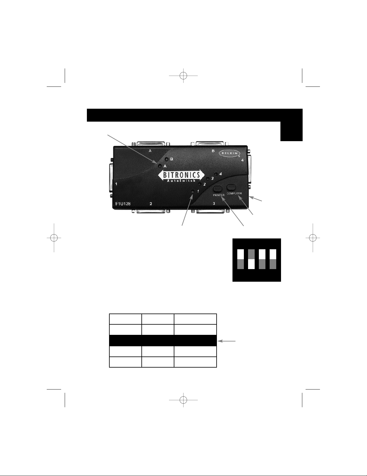
DIP switch settings (located underneath switch):
SW1: Reset Switch
To reset, OFF→ON→OFF
SW2 and SW3: TimeOut Setting
TimeOut is the amount of time the switch remains locked on a PC port after
data transfer. Use a longer TimeOut when connecting to scanners, mass
storage devices and for large print jobs.
Product Detail
Device activity LEDs
Connector to Device A
Connector to Device B
Connector to PC2
PC activity LEDs
Recommended
Printer button
Computer button
DC power jack
(side)
Connector to PC3
ON DIP
1234
ON is UP. SW4 is not used.
SW2
ON ON 5 seconds
ON OFF 10 seconds
OFF ON 20 seconds
OFF OFF 40 seconds
SW3 TimeOut
En
Connector
to PC1
Connector
to PC4
P73046_F1U128uKIT univ_man.qxd 4/28/00 2:12 PM Page 3
Page 8
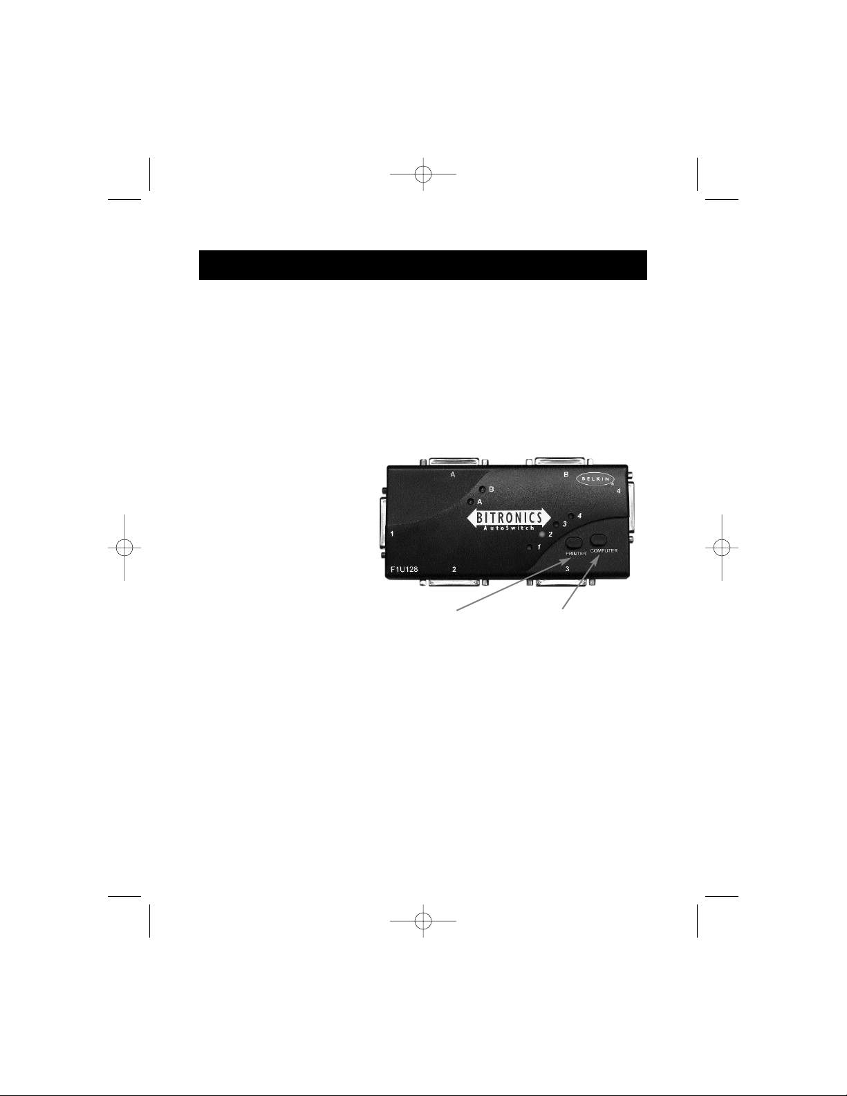
In manual mode, you can select a port manually through the buttons on the
Bitronics switch. You can also use this mode in conjunction with software to
see your switch in action!
• Press COMPUTER to select which computer port you wish to configure or
monitor. For the computer connected to Port 1, press the COMPUTER
button until the LED on Port 1 is lit up either in red or green.
• Press the PRINTER button until the LED of the appropriate device port
you wish to use is lit up.
For example, if you want
computer 2 to use the
device on port B, press the
COMPUTER button until the
LED on "2" is lit up. Then,
press the PRINTER button
until LED "B" is lit up.
To use File Transfer mode, press the PRINTER button until the LED on the
computer port turns green. When the LED turns green, the port is ready for
file transfer mode. For file transfer mode to be successful for both PCs, both
computer ports must be set to file transfer mode – which is evident when the
LEDs next to 1 and 2 are green. For more information on File Transfer, please
see page 25.
Note: Computer 1 can only file transfer to computer 2, and computer
3 can file transfer to computer 4. If you change the ports
manually using the buttons, the changes made will not be
reflected in the software.
4
Manual Mode and Port Monitoring
Printer button
Computer button
P73046_F1U128uKIT univ_man.qxd 4/28/00 2:12 PM Page 4
Page 9

5
Windows®3.x . . . . . . . . . . . . . . . . . . . . . . . . . . . . . . . . . . . . . . . . . Page 6
MS-DOS . . . . . . . . . . . . . . . . . . . . . . . . . . . . . . . . . . . . . . . . . . . . . Page 7
Windows
®
95/98 and NT®. . . . . . . . . . . . . . . . . . . . . . . . . . . . . . . . . Page 8
NOTE: When installing software on any operating system, the
software must be installed on all the computers connected to
the Bitronics switch so that each machine can control the
switch properly.
Choose your operating system
En
P73046_F1U128uKIT univ_man.qxd 4/28/00 2:12 PM Page 5
Page 10
6
Software installation: Windows®3.x
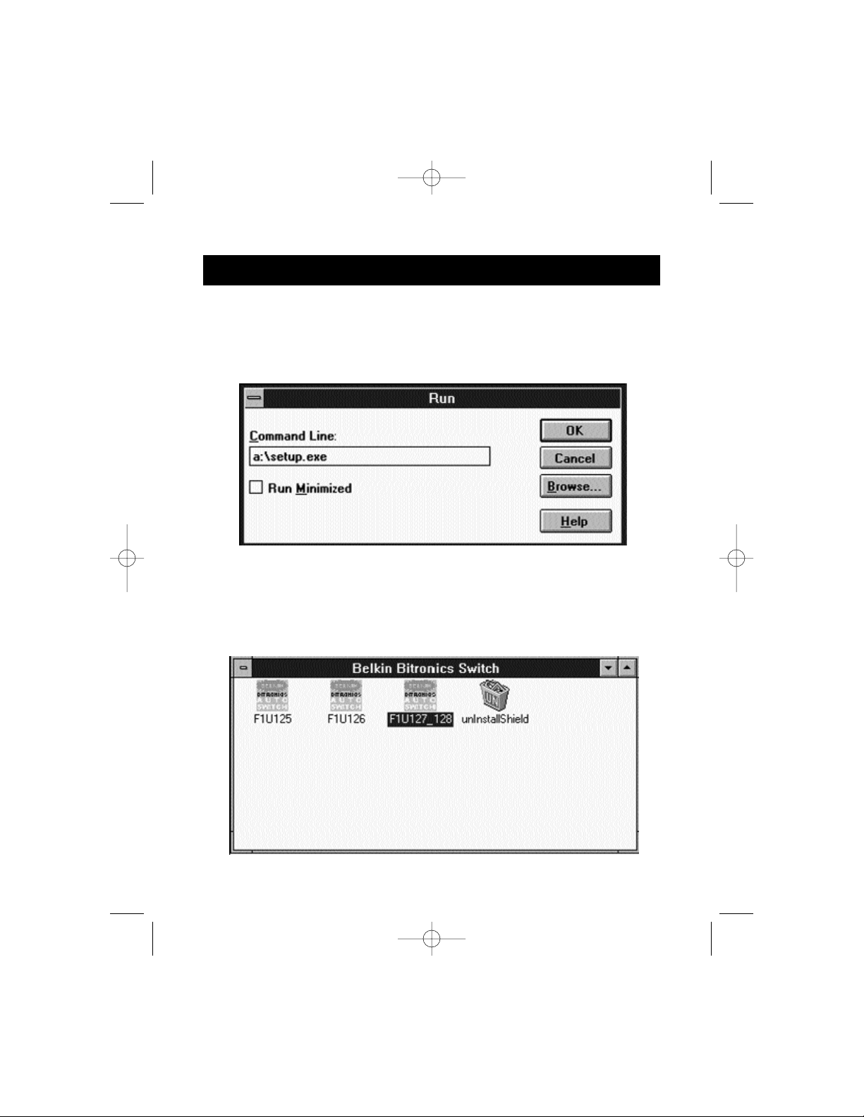
Insert the diskette labeled P27236 in your floppy drive. In the Program
Manager, click on FILE then click RUN. In the space, type in "a:\setup.exe".
Follow the installation instruction prompts. After the setup program is done,
simply double-click on the correct icon to run the port selection program.
P73046_F1U128uKIT univ_man.qxd 4/28/00 2:12 PM Page 6
Page 11
7
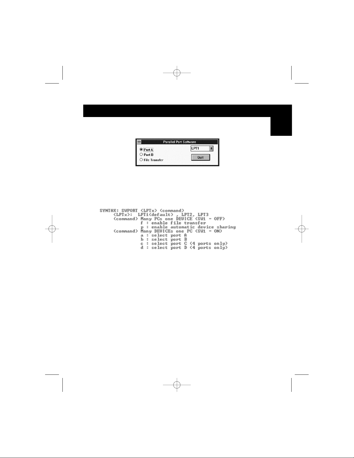
Software installation: MS-DOS
To switch port, simply click on the port letter of your choice, and your
computer will be connected to the device on the port chosen.
Software-Installation: MS-DOS
Enter the following at the DOS prompt and press ENTER:
Copy a:\dos\swport.com c:\SWPORT.com
SWPORT.com is a command-line executable. Please follow the syntax for
proper operation:
File Transfer in DOS and WINDOWS®3.x:
The file transfer feature of the Bitronics switch allows both computers to
connect a if there was a file transfer cable connected between them.
The LED of the corresponding computer port on the Bitronics switch will
turn green. This LED represents the computer you are on now, and is set for
file transfer mode.
The LED of the corresponding computer port on the Bitronics switch will
turn green. This LED represents the computer you are on now is set for file
transfer mode. Note that PC1 can only file transfer to PC2, and PC3 can
only file transfer to PC4. When both sets of PC LEDs on the Bitronics switch
are green, then the computers are ready for file transfer. At this point, the
cables and the Bitronics switch act as if it was a file transfer cable. You can
now run programs such as Windows‚ Direct Cable Connection, or LapLink
®
.
Please refer to their user manuals or websites for information on how to
configure their software. Just remember that your Bitronics switch setup
mimics the file transfer cable requirement.
En
P73046_F1U128uKIT univ_man.qxd 4/28/00 2:12 PM Page 7
Page 12

8
BEFORE YOU INSTALL THE BELKIN BITRONICS SOFTWARE, YOU MUST
FIRST MAKE SURE THAT EACH DEVICE WORKS PROPERLY ON ITS OWN
WITH EACH COMPUTER. DO NOT CONNECT THE BITRONICS SWITCH TO
THE COMPUTERS OR INSTALL THE SOFTWARE UNTIL INSTRUCTED BY
THIS PROCEDURE!
1. Make sure that the printer port on your computer is set to ECP mode. To
do this, you must go into your computer’s BIOS or CMOS setup.
Instructions on how to do this differs from one computer to the next.
Please consult your computer manufacturer’s manual, tech support, or
website for information on how to do this. Please do not call Belkin Tech
Support regarding this because each computer’s BIOS setup routine is
different. Refer to the Appendices at the end of this manual for
information on several models of computers.
The BIOS setup routine prompt is displayed a few seconds after you turn
on your computer and hear its first beeps. Again, this varies from PC to
PC. Please consult the Appendices and/or your computer manufacturer’s
manual or their tech support for information on how to do this properly.
Usually you will see a message that reads PRESS DEL TO ENTER SETUP or
PRESS F2 TO ENTER SETUP. When in the setup program, there may be a
selection for "Integrated Peripherals", or "Peripheral Setup". Then, look
for "Parallel Port Type" or "LPT port type". Change that setting to say
"ECP" or "ECP/EPP". Save your settings then exit. When Windows
®
restarts, it may find new hardware, and it may ask you for the Windows
®
CD. Be prepared to insert the CD into the computer.
2. Make sure that the software and drivers for the devices to be shared are
properly installed on all computers.
For instance, if you are sharing a Zip
®
Drive and a printer between 2
computers, you will need to first connect and install the Zip
®
Drive drivers
on the first PC. Make sure that the Zip
®
Drive works perfectly on it, then
repeat the same installation process for the second PC. Then, you will
need to do the same installing the printer’s driver on both PCs as well.
This way, all the PCs have the drivers properly loaded so each one can
access either device without any problems, as if they were connected to
the computer individually.
Windows®95 / 98 and NT
®
P73046_F1U128uKIT univ_man.qxd 4/28/00 2:12 PM Page 8
Page 13
9
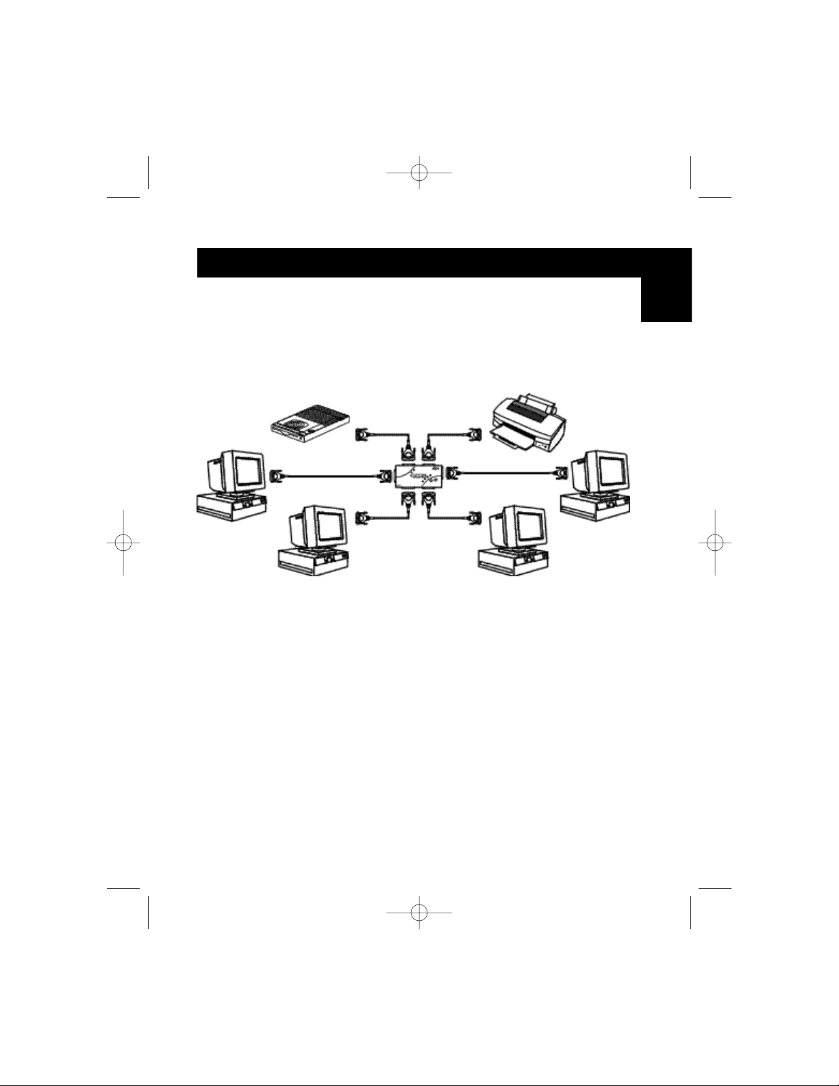
3. Connect four computers and the devices to be shared to the Bitronics
Switch as shown below. Two cables that connect computers to the
Bitronics switch are included. Take note of which port each device is
connected to:
Connect the power adapter to the power jack on the side of the switch,
and plug it into an outlet. The example shown has a Zip
®
Drive connected
to Port A and an InkJet printer on Port B of the switch.
Windows®95 / 98 and NT
®
(continued)
En
Device A
connected to Port A
These two cables
are included
Device B
connected to Port B
P73046_F1U128uKIT univ_man.qxd 4/28/00 2:12 PM Page 9
Page 14
10
4. In order for all computers to properly share the devices, the software must
be installed on all four computers.
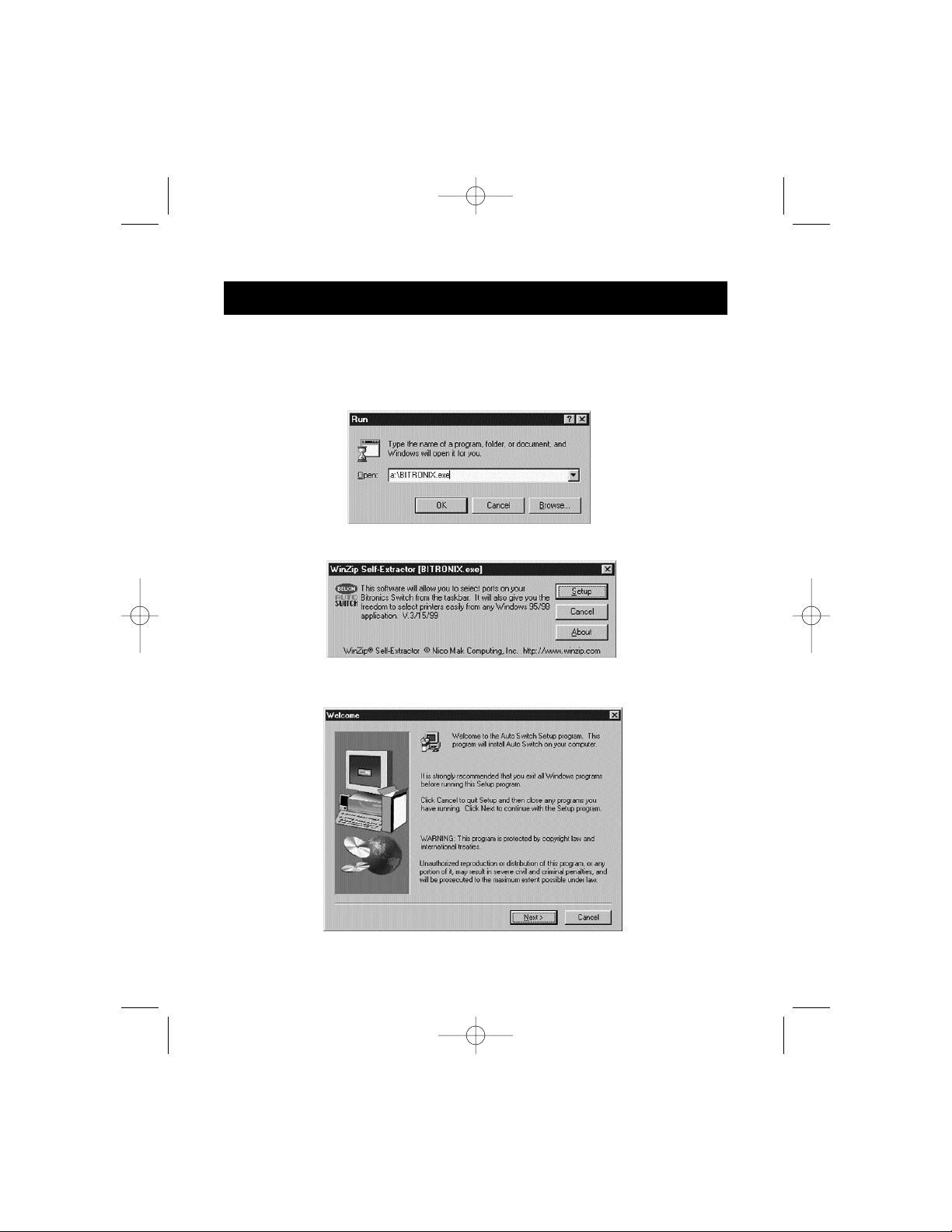
4.1. Insert the disk into your floppy drive. Click on Start, then click Run.
Enter a:\BITRONIX.exe, then click OK.
4.2. You will see the following window. Click Setup.
4.3. Close all other running applications so that the software installation
can proceed quickly and smoothly. Click Next.
Windows®95 / 98 and NT
®
(continued)
P73046_F1U128uKIT univ_man.qxd 4/28/00 2:12 PM Page 10
Page 15
11
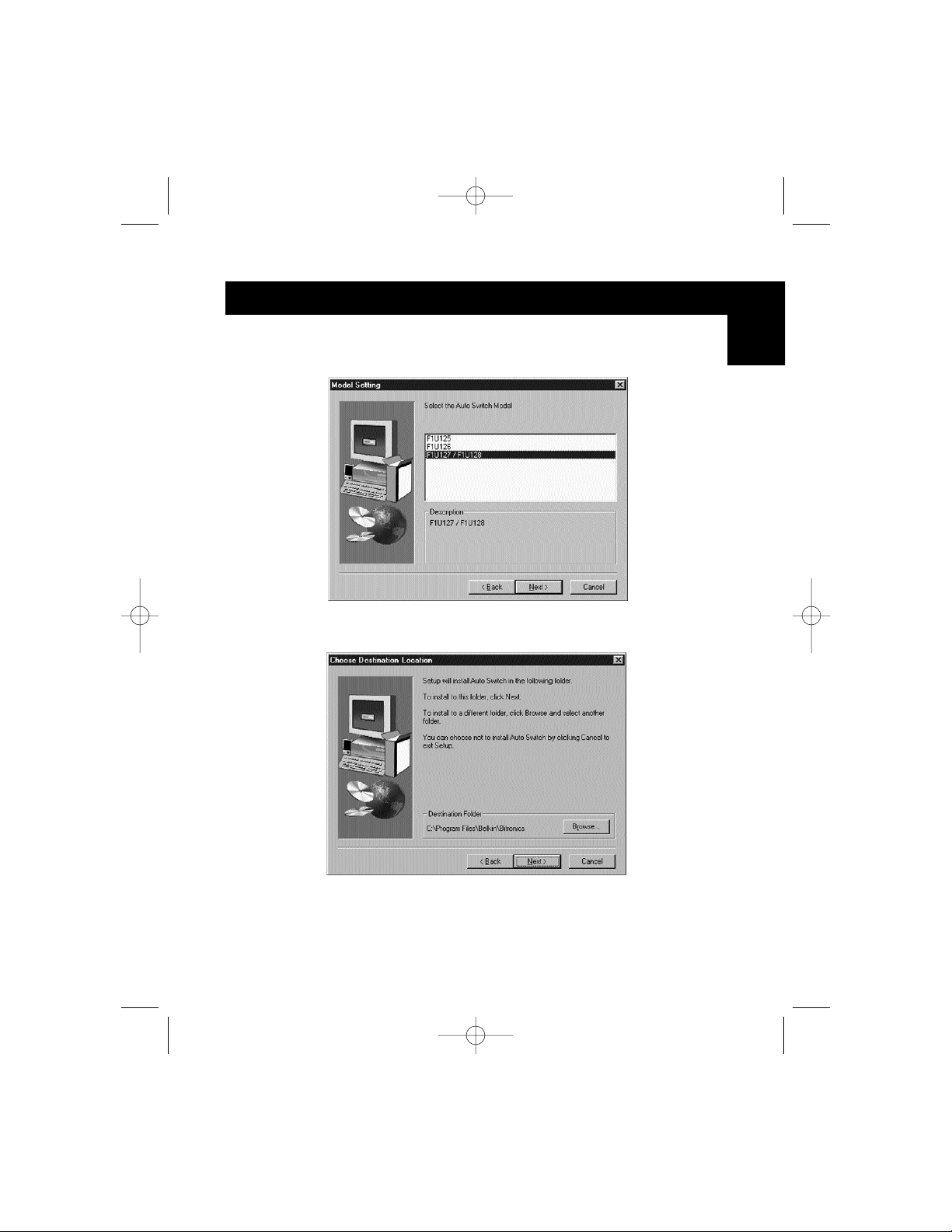
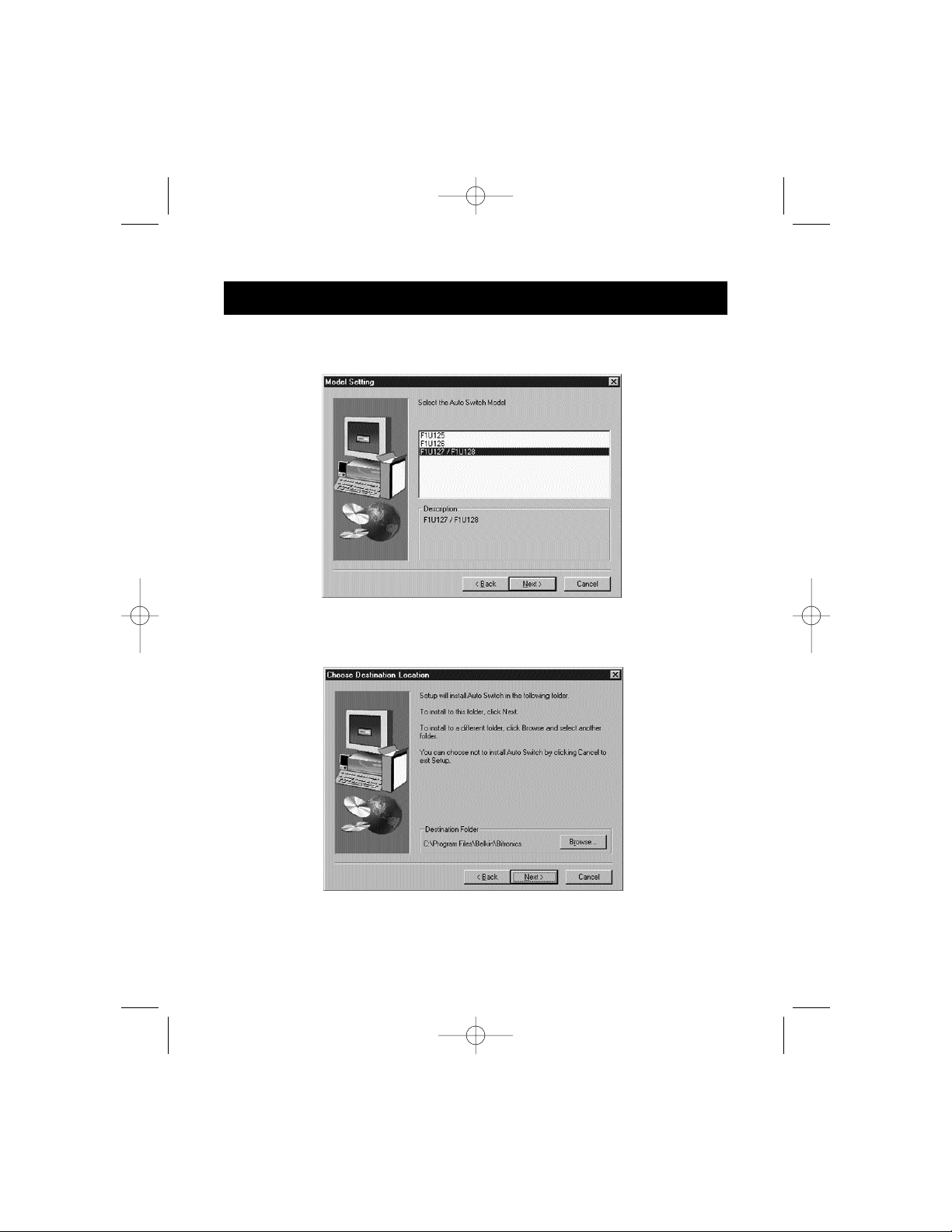
4.4. Select the model of the Bitronics Switch you have, which is the
F1U127 / F1U128. Click Next.
4.5. Select Destination Folder. The default folder is recommended.
Click Next.
Windows®95 / 98 and NT
®
(continued)
En
P73046_F1U128uKIT univ_man.qxd 4/28/00 2:12 PM Page 11
Page 16
12
Windows®95 / 98 and NT
®
(continued)
4.6. Select Program Folder. The default, Belkin Bitronics Switch, is the
recommended. Click Next.
4.7. When done installing, the program will ask you to restart your
computer. You must restart in order to activate the software properly.
Click Finish.
Don’t forget to remove the disk from your floppy drive before
restarting your computer!
P73046_F1U128uKIT univ_man.qxd 4/28/00 2:12 PM Page 12
Page 17
13
Windows®95 / 98 and NT
®
(continued)
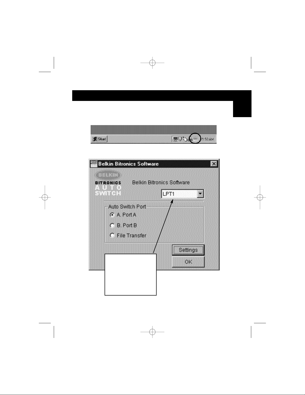
5. Once your computer has rebooted, the Bitronics icon will appear in
your system tray. This is how you can easily control and configure the
Bitronics Switch.
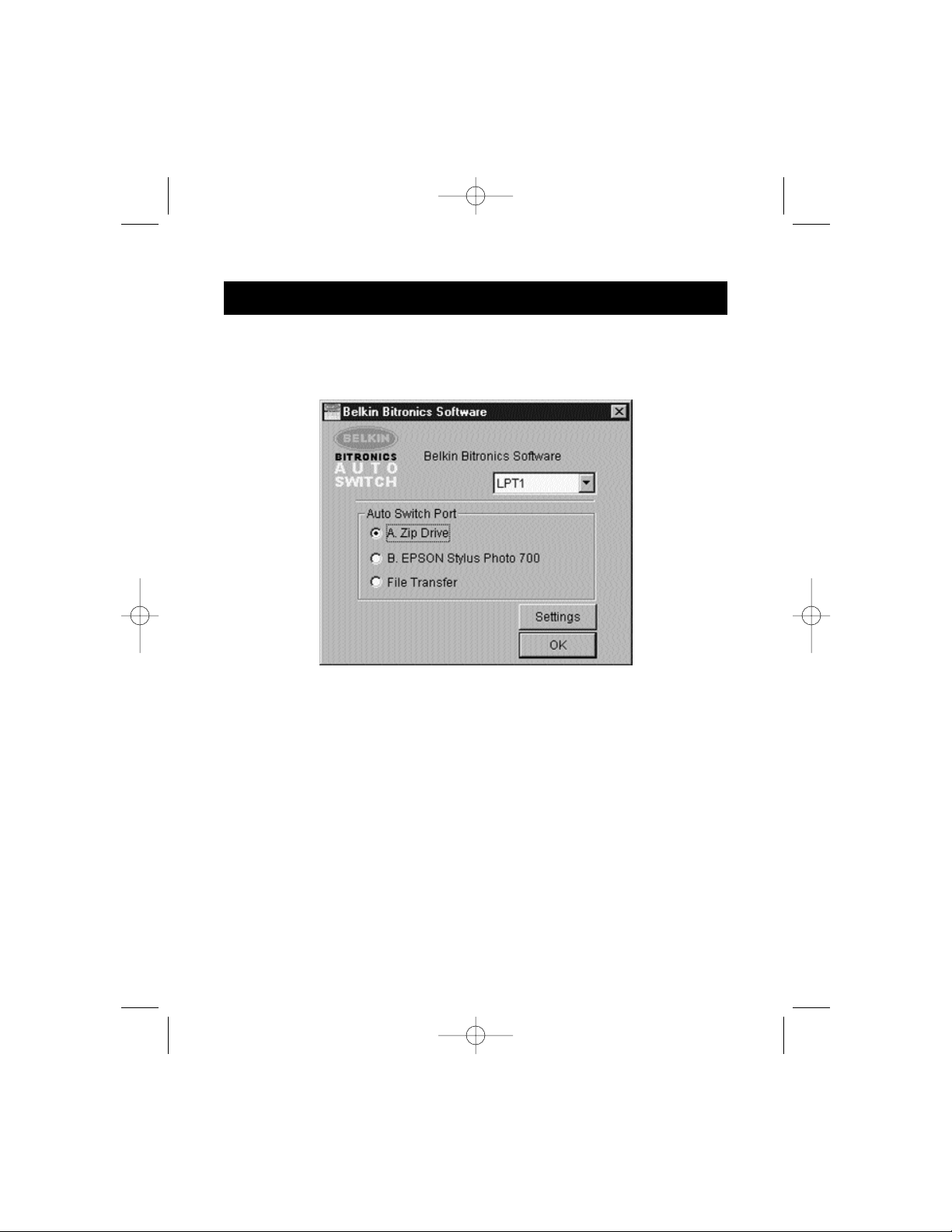
6. Double-click on the icon to open up the setup program:
Select the correct LPT
port the Bitronics
switch is connected to.
If you only have ONE
parallel port (usually
that is the case), leave
this in LPT1.
En
P73046_F1U128uKIT univ_man.qxd 4/28/00 2:12 PM Page 13
Page 18
14
Windows®95 / 98 and NT
®
(continued)
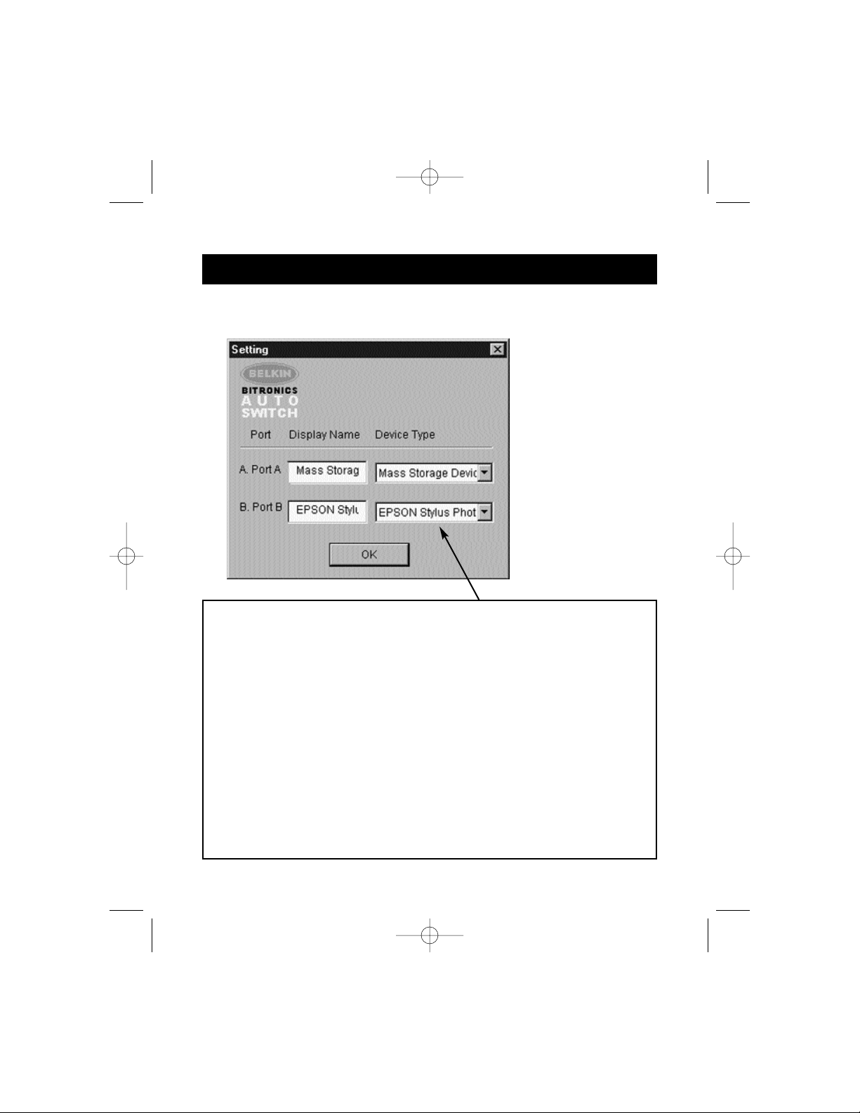
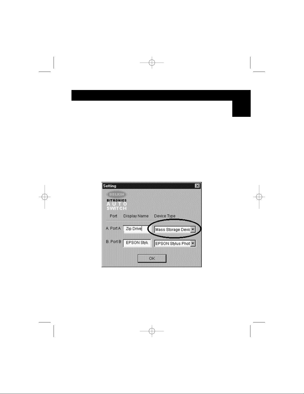
7. Click on Settings. This is where you tell the software what devices are
connected to each port:
Device Type gives you a pull-down menu showing the types of printers
installed on your computer and other possible parallel device types as well.
Here, you must select the correct type for the device connected to that port.
• If you are using a device which adds a drive letter to your system (like a
Zip
®
Drive, CD-ROM, LS-120, etc...), use the Mass Storage
Device setting.
• If you are using a printer, use the printer driver used for that particular
printer on that port of the Bitronics switch. If it does not show up in this
menu, that means the printer drivers have not been installed. (In that
case, reinstall the printer drivers and repeat this step after rebooting
your computer.) If you have more than one printer installed, make sure
that the correct driver is used for the printer connected to that port on
the Bitronics switch.
• For any other parallel device, just use Scanner, and change the Display
Name accordingly. For example, if you have a parallel tape drive, use
Scanner for Device Type, then enter Tape Drive in Display Name.
P73046_F1U128uKIT univ_man.qxd 4/28/00 2:12 PM Page 14
Page 19
15
Windows®95 / 98 and NT
®
(continued)
En
In our example, we have a Zip®drive on Port A, so we chose Mass Storage
Device for Port A. And in Port B, we have the Epson printer installed, so we
chose that driver in the Device Type for Port B.
Click OK when finished.
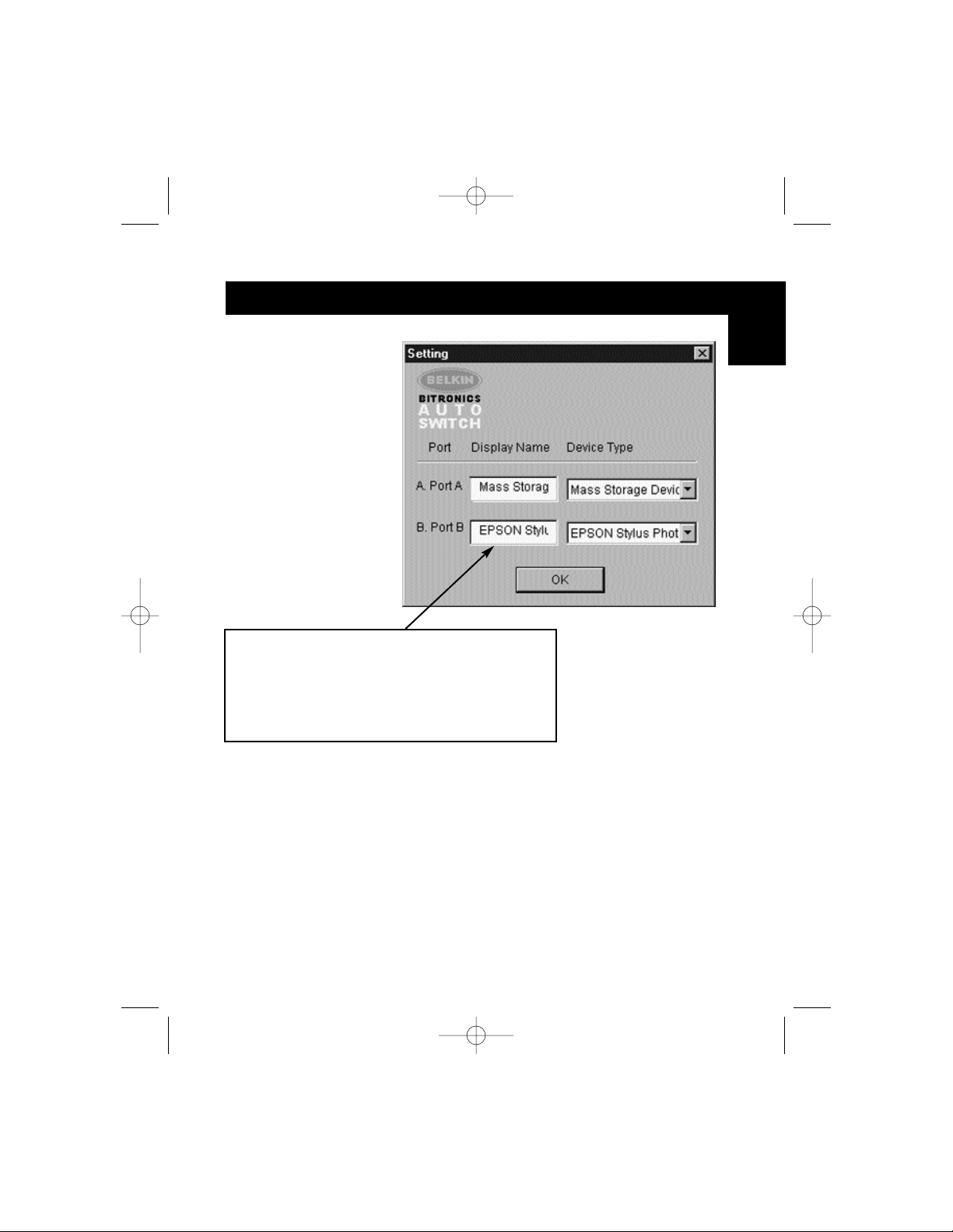
Display Name is a free text field. You can enter
any description here for the attached devices. For
instance, Port A has the Zip
®
Drive connected and
Port B has the InkJet connected. You can rename
these fields to say "My Zip Drive" and "Color
Printer #2".
P73046_F1U128uKIT univ_man.qxd 4/28/00 2:12 PM Page 15
Page 20
16
Windows®95 / 98 and NT
®
(continued)
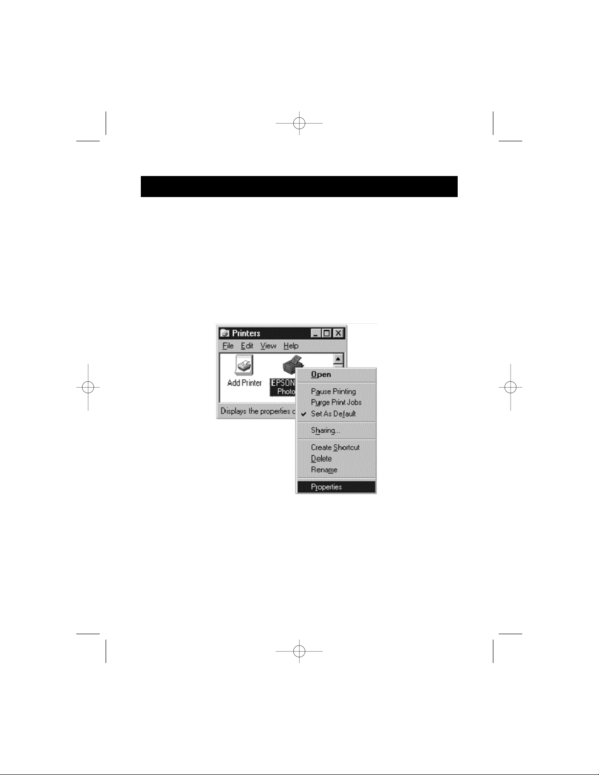
8. Change printer port from LPT1 to AutoSwitch port:
If one or both of the devices being shared is a printer, you must follow the
procedure below to reconfigure the port connected to the printer. If both
devices are printers, then this must be done for both printers. If neither
device is a printer, then you can skip this step.
8.1. Click on Start, select Settings, and double-click on Printers.
8.2. Right-click on the printer installed on the Bitronics switch, and click
on Properties:
P73046_F1U128uKIT univ_man.qxd 4/28/00 2:12 PM Page 16
Page 21
17
Windows®95 / 98 and NT
®
(continued)
En
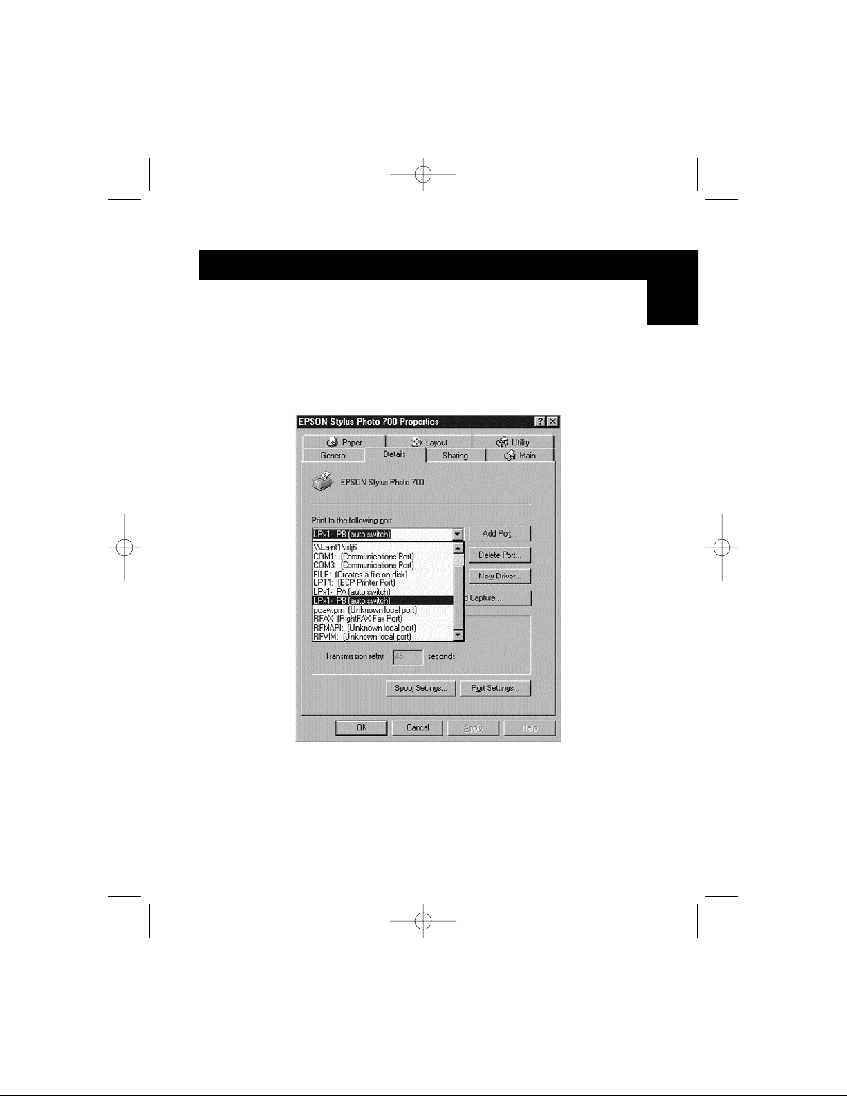
8.3. Click on the Details tab. In the pull-down menu Print to the
following port:, select the correct port this printer is connected to
on the Bitronics switch:
• LPx1 – PA (autoswitch) – Select this if the printer is connected to
Port A of the Bitronics switch.
• LPx1 – PB (autoswitch) – Select this if the printer is connected to
Port B of the Bitronics switch.
In the image above, the printer is connected to Port B of the
Bitronics switch. Therefore, LPx1 – PB (autoswitch) is selected.
When finished, click OK.
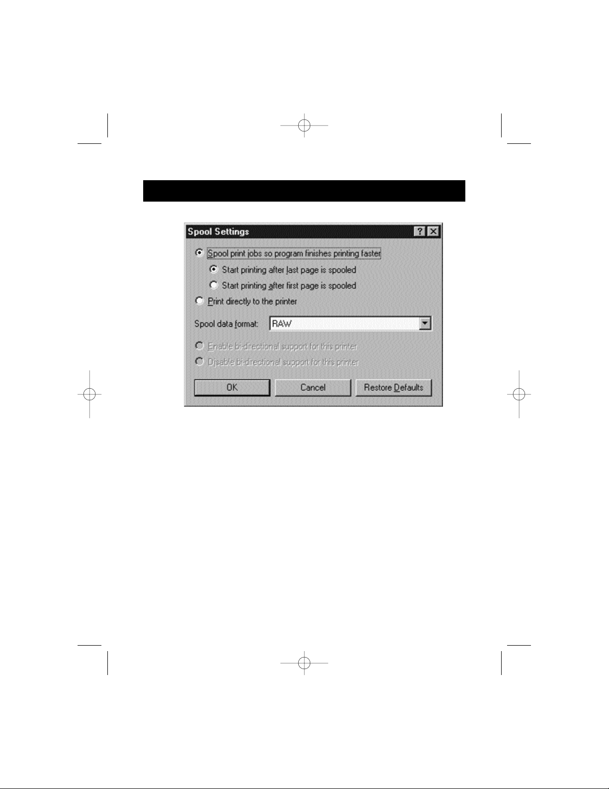
8.4. Click on Spool Settings and click on Start printing after last page
is spooled.
P73046_F1U128uKIT univ_man.qxd 4/28/00 2:12 PM Page 17
Page 22
18
Windows®95 / 98 and NT
®
(continued)
8.5. If NOT grayed out, click on Disable bi-directional support for this
printer. Otherwise, ignore.
8.6. Click OK in the Spool Settings window. Click OK again in the main
properties window.
Using the Bitronics Software
Example: Two Printers Shared Between Two Computers
The Bitronics Software automatically handles printing chores by directing your
print jobs to the correct port on the Bitronics switch based on the settings you
set in the Printer Properties and the Settings in step 7 previously. When you
print something in any Windows
®
application (like MS Word or Excel), you
simply select the printer you wish to print to, and the Bitronics software
handles the switching duties. IT IS FULLY AUTOMATIC!
P73046_F1U128uKIT univ_man.qxd 4/28/00 2:12 PM Page 18
Page 23
19
Windows®95 / 98 and NT
®
(continued)
How does it work?
With the Bitronics Software loaded and the ports properly configured for the
printers as shown in step 8 above, when you print in Windows
®
, the print job
goes to the Bitronics software first. There, the Bitronics software adds a
command in the beginning of the print job telling the Bitronics Switch which
port to send the print job to.
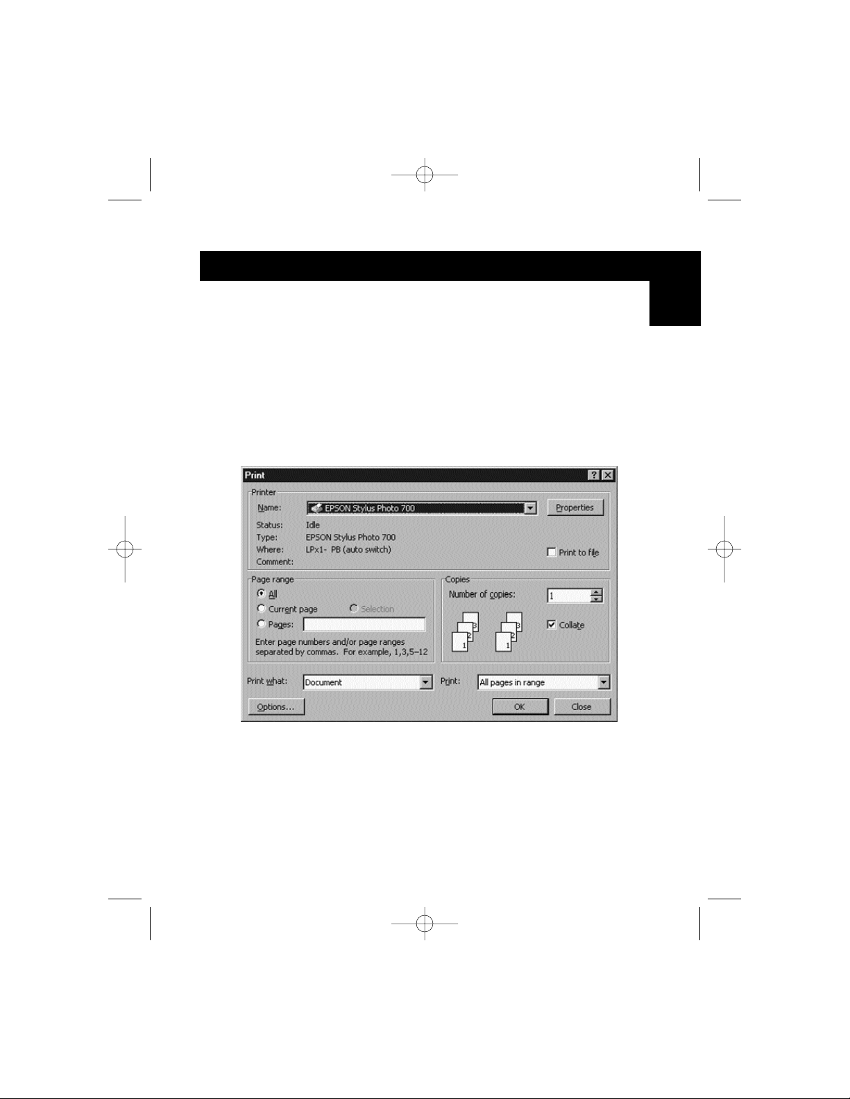
In the example below, the Epson Printer is connected to Port B, as described
in the Where: line. When printing, the Bitronics software tells the Bitronics
switch to switch to Port B first, then allows the print job to go through the
switch, out to Port B, and to the Epson printer.
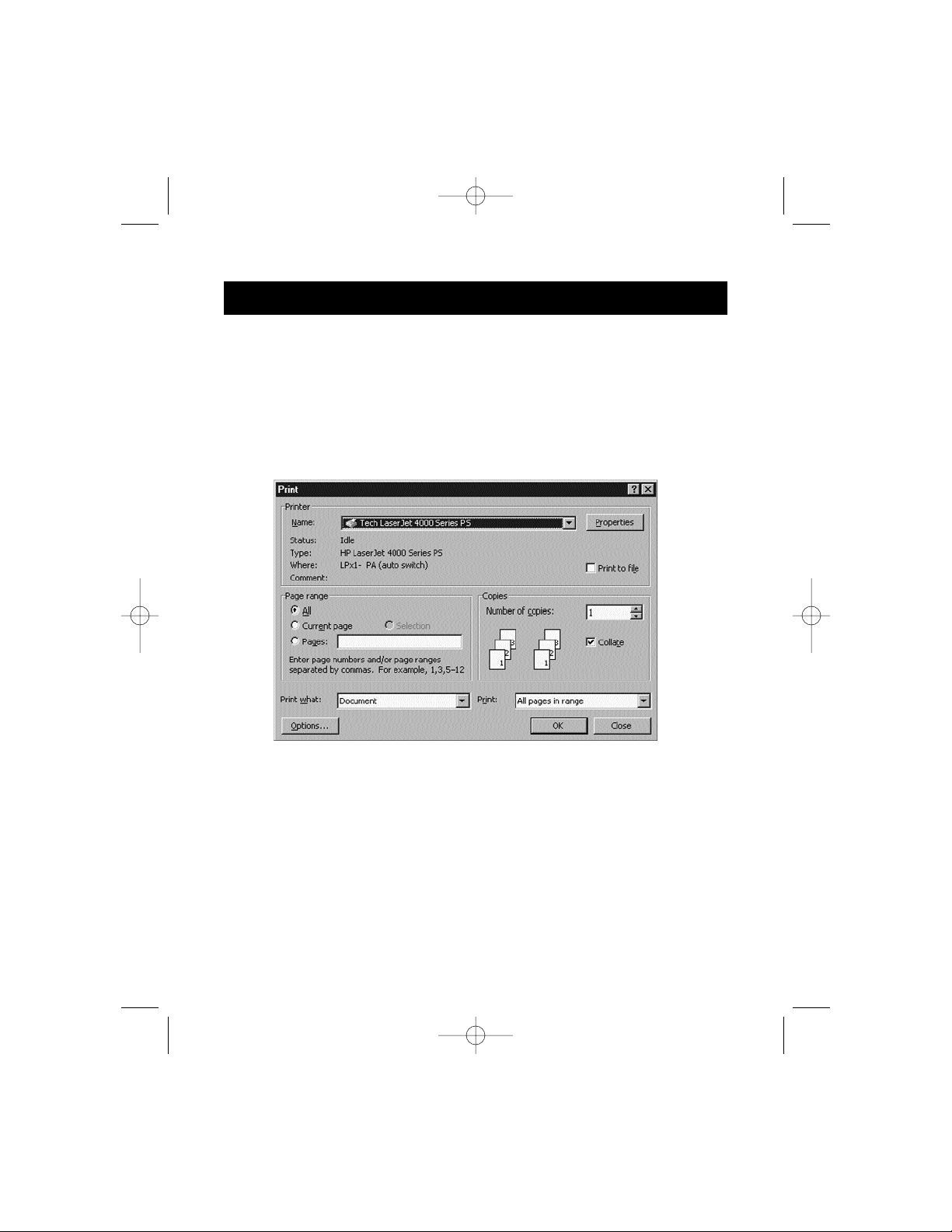
Then if you wish to print to the second printer, let’s say a LaserJet
™
for
example, all you have to do is select that particular printer in the Print dialog
box. Click OK, and the print job is automatically sent to the LaserJet
™
printer
on Port A of the Bitronics switch.
En
P73046_F1U128uKIT univ_man.qxd 4/28/00 2:12 PM Page 19
Page 24
20
Windows®95 / 98 and NT
®
(continued)
All you have to do is pick your printer, and the software does everything else.
But remember, ALL THE SETTINGS MUST BE CORRECT, otherwise you may
print garbage out of the wrong printer!
Below, the user has chosen the LaserJet
™
printer. Here, this printer is
connected to Port A of the AutoSwitch. When the print job is sent, the
Bitronics software tells the Bitronics switch to switch to Port A, then lets the
print job go through to the LaserJet
™
.
P73046_F1U128uKIT univ_man.qxd 4/28/00 2:12 PM Page 20
Page 25
21
Windows®95 / 98 and NT
®
(continued)
En
EXAMPLE: Sharing One Printer and a Zip®drive (or any other mass
storage device)
When dealing with a mass storage device (devices that add a drive letter to
your system like E:) such as a Zip
®
drive, the Bitronics Software in the system
tray must be configured so that the Bitronics switch is defaulted to the Port
attached to the Zip
®
drive. It is necessary for the switch to always remain
connected to the Zip
®
drive so that any time you access that drive, you will
always be connected, and not receive error messages:
1. Make sure that the port that connects to the Zip
®
drive is set to
Mass Storage Device in Settings. See Step 7 above for more info.
The image below shows the Zip
®
drive is connected to Port A, and
that the device type is Mass Storage Device. Type anything you
want in Display Name. Click OK when finished.
P73046_F1U128uKIT univ_man.qxd 4/28/00 2:12 PM Page 21
Page 26
22
Windows®95 / 98 and NT
®
(continued)
2. Click on the port that has the mass storage device connected. In this
case, it is a Zip
®
drive on Port A. As you can see, the Display Name
entered above appears below as you had entered it. Click OK.
Now, the Bitronics switch will always keep your computer connected to the Zip
®
drive. That way, anytime you access it, you will not get any strange errors.
Then, when you print to the Ink Jet Printer on Port B (as shown above), the
Bitronics switch will switch to Port B temporarily to send the print job, then
switch back to Port A to keep communication with the Zip
®
drive.
P73046_F1U128uKIT univ_man.qxd 4/28/00 2:12 PM Page 22
Page 27

23
Windows®95 / 98 and NT
®
(continued)
En
Visual Feedback – How do I know what port I am on?
When the Bitronics switch is in its normal scanning mode, the LEDs are
moving back and forth across the computer ports. To see the software in
action, simply press the COMPUTER button so you can see a computer
port’s connection. Press the COMPUTER port until the LEDs around 1 are lit
up, and you will see which device port it is currently connected to. If it is in
File Transfer mode, the computer port LEDs are green, and neither device
port LEDs will be lit. Then, click on the Bitronics software icon in the taskbar
and change ports. You will see the LED of the Bitronics switch to the port
you chose.
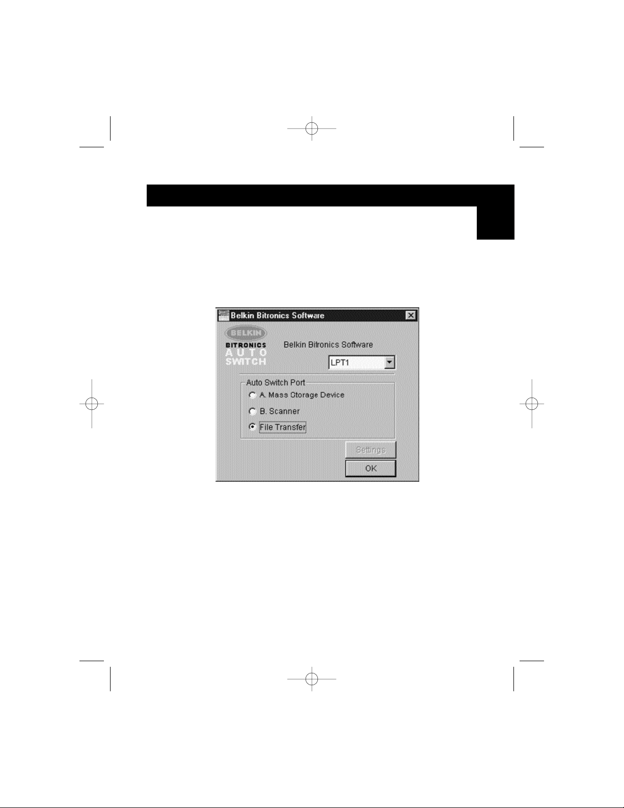
Using any other parallel device (not printers or mass
storage devices) with a printer
When dealing with other parallel port devices, they are set as Scanners in
the Settings (step 7 above). Examples of these are scanners, parallel port
cameras, and tape drives. When you need access to this device, simply
single-click on the Bitronics system tray icon, and select the device you wish
to use. A check mark will appear showing which device is connected. For
example, we have a scanner and a printer on the Bitronics switch:
You will be connected to the scanner device indefinitely. But let us say
you wish to print to the InkJet printer, the software will again
automatically switch to the port that has the printer and send the print
job. However, the switch will remain connected to the printer - it will not
change back to the Scanner, unlike the mass storage device mentioned
previously. This means that you have to use this method to switch to the
scanner each time you need to use it.
P73046_F1U128uKIT univ_man.qxd 4/28/00 2:12 PM Page 23
Page 28

24
Windows®95 / 98 and NT
®
(continued)
If no printers are installed
If no printers are installed, the Settings type (see step 7) for each device must
be set either for Mass Storage Device (if the device adds a drive letter to your
system), or Scanner (for all other types of devices).
The Bitronics software may not function properly in some systems if there is no
Default Printer set. To do this, add a printer using the Add Printer Wizard
(click Start, select Settings, double-click on Printers), and just use the
Generic/Text Only driver. Remember to use Local Printer and LPT1 when the
wizard asks you. This will then be set as your default printer, so that the
Bitronics software can work properly.
Removing and Adding the Bitronics Switch Icon from
the System Tray
• To remove the icon, simply right click on it, and answer Yes to
the prompt.
• To reload the icon back into the system tray, click on Start, select
Programs, select Belkin Bitronics Switch and select
AutoSwitch-Multi PCs.
ADVANCED USER TIP:
If you are using devices with pass-through ports (like Zip®Drives and
Scanners), you can connect a printer to the pass-through port and use the
other device port on the Bitronics switch to connect to another device. Just be
sure that the printer driver has its Port set to the correct device port. For
example, if you wish to share 2 printers, 1 Zip
®
Drive and 1 scanner between 2
computers, connect the Zip
®
Drive to Port A, the Scanner to Port B, the first
printer to the pass-through of the Zip
®
Drive, and the second printer to the
pass-through of the scanner. In the Bitronics software, set Port A to Mass
Storage Device, and Port B to Scanner. Then in the Printer Properties/ details,
set the Print to the following Port to LPx1- PA (auto switch) for the first printer,
and LPx1- PB (auto switch) for the second printer. In general, only printers can
be connected to pass-through ports.
P73046_F1U128uKIT univ_man.qxd 4/28/00 2:12 PM Page 24
Page 29
25
Windows®95 / 98 and NT
®
(continued)
En
Using the File Transfer Feature
The file transfer feature of the Bitronics switch allows both computers to
connect as if there were a file transfer cable connected between them. To
do this, double-click on the Bitronics switch system tray icon, click on File
Transfer, and click OK. The LED of the corresponding computer port on the
Bitronics switch will turn green. This LED represents the computer you are
on now is set for file transfer mode.
Next, the second PC must also perform the same operation. When both sets
of PC LEDs on the Bitronics switch are green, then the computers are ready
for file transfer. At this point, the cables and the Bitronics switch act as if it
were a file transfer cable. You can now run programs such as Windows
®
Direct Cable Connection, or LapLink®. Please refer to their user manuals or
websites for information on how to configure their software. Just remember
that your Bitronics switch setup mimics the file transfer cable requirement.
NOTE: Computer 1 can only file transfer to computer 2, and computer
3 can file transfer to computer 4. If you change the ports
manually using the buttons, the changes made will not be
reflected in the software.
P73046_F1U128uKIT univ_man.qxd 4/28/00 2:12 PM Page 25
Page 30
26
Windows®95 / 98 and NT
®
(continued)
Usage in Windows NT
®
In Windows NT®, you can perform the same installation as in the Windows®95/
98 procedure above. Make sure the power supply is connected to the
Bitronics switch, otherwise, there may be a significant delay in the processing
of requests from NT
®
-based machines.
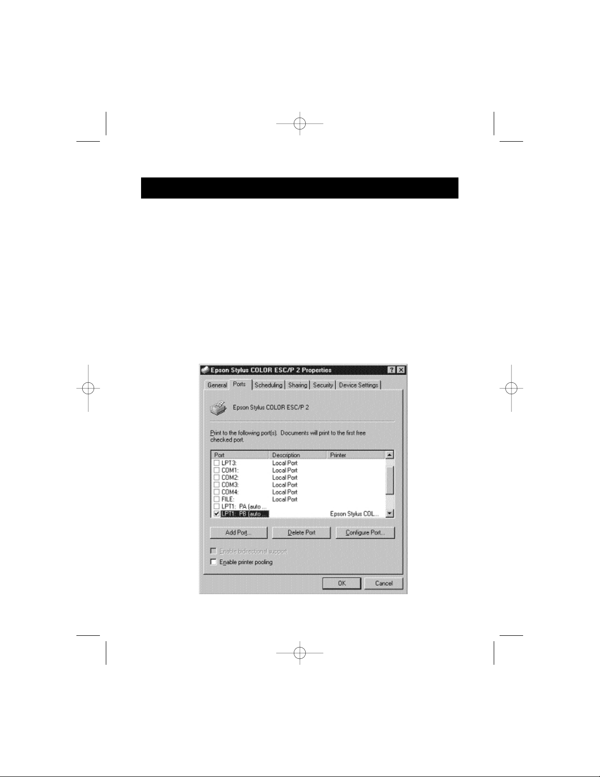
The Printer properties in Windows NT
®
is slightly different. After installing the
software and restarting the computer, go to the printer properties and select
the Ports tab. To find the correct ports to be used with the Bitronics switch,
you must scroll down the list until the LPx1: PA (autoswitch) comes up. Put a
checkmark on the port that connects to the printer. In this case, it is Port A on
the Bitronics switch:
P73046_F1U128uKIT univ_man.qxd 4/28/00 2:12 PM Page 26
Page 31

Windows®95 / 98 and NT
®
(continued)
27
To set the spool settings correctly, click on the SCHEDULING tab. Make sure
"Start printing after last page is spooled" is selected. Also, set "Priority" to
highest:
Click OK when done.
En
P73046_F1U128uKIT univ_man.qxd 4/28/00 2:12 PM Page 27
Page 32

Windows®95 / 98 and NT
®
(continued)
28
If you are still having problems using the BITRONIX.exe
software in Windows
®
NT:
First UNINSTALL the Bitronics software. You can do this by right-clicking on
the taskbar icon and answering YES to the prompt. Then, click on START,
PROGRAMS, BELKIN BITRONICS SWITCH, then UNINSTALLSHIELD.
After restarting your computer, you can install the older NT version of the
software located in the second disk (part# P72736). During the installation, it
will ask you the model number. Please select "Auto Switch 2-2 / 4-2":
This version of the software is not fully automatic in printer selection. It
requires the user to select ports each time through the taskbar icon.
P73046_F1U128uKIT univ_man.qxd 4/28/00 2:12 PM Page 28
Page 33

Appendix
Changing your PC’s parallel port mode to ECP
Changing your computer’s parallel port mode to ECP increases speed and reliability of
data transfers with the Bitronics Switches. Below are the steps on changing the settings
on certain computers. Do this on all the computers connected to the switch. If your
computer is not listed here, please check their website, or call their technical support.
Please do not call Belkin Tech Support on this particular issue.
ACER
1. While the computer is booting, follow the directions on the screen: To enter
Setup, press CTRL+ALT+ESC.
2. Follow the legend on how to scroll through the options.
3. When you reach the option Parallel Port Mode, choose ECP.
4. Follow the legend directions to save the setting and exit Setup.
AST
1. While the computer is booting, follow the directions on the screen: To enter
Setup, press CTRL+ALT+ESC. (If you have a 486 computer, the directions might
say press CTRL+ALT+DEL).
2. Follow the legend directions on how to scroll through the options.
3. When you reach the Parallel Port Mode option, choose the mode with the
highest performance (e.g. ECP).
4. Follow the legend directions to save the setting and exit.
Generic clone computer
1. Restart the computer and press F1 during the startup.
2. Use an arrow key to select the Advance menu item.
3. Use an arrow key to select the parallel port setting and the mode field.
4. Press ENTER to get the mode list.
5. Select the mode with the highest performance (e.g. ECP) and then press ENTER.
6. Press F10 to save the BIOS (basic input/output system) changes.
7. Press ENTER to close the BIOS settings window.
Dell
1. While the computer is booting, follow the directions on the screen: To enter
Setup, press DEL. (If you have a 486 computer, the directions might say press F2.)
2. Press ALT+P and choose Parallel Mode.
3. There should be a list of modes available. Choose the mode with the highest
performance (e.g. ECP).
4. Follow the legend directions to save the setting and exit Setup.
Gateway 2000
1. While the computer is booting, follow the directions on the screen: To enter
Setup, press F1.
2. Select Advanced from the menu bar.
3. Select Integrated Peripherals.
4. Following the legend directions, select ECP as the parallel port mode.
5. Follow the legend directions to save the setting and exit Setup.
29
En
P73046_F1U128uKIT univ_man.qxd 4/28/00 2:12 PM Page 29
Page 34

30
Appendix (continued)
Hewlett-Packard
Steps for HP Pavillion PC Models
1. At the HP Blue Screen, press F1 to enter Setup.
2. Select Advanced from the menu bar.
3. Following the legend directions, select Peripheral Configuration and then use the
arrow-down key to move to Parallel Port Mode.
4. Select the mode with the highest performance (e.g. ECP).
5. Follow the legend directions to save the setting and exit Setup.
Steps for HP Vectra PC Series
1. While the computer is booting, follow the directions on the screen: Press F2 to
Enter Setup. This is displayed at the bottom of the Hewlett Packard System
Hardware Test screen.
2. Use the arrow keys to highlight Parallel Port Mode.
3. Follow the legend directions on how to change the options.
4. Set the port mode with the highest performance (e.g. ECP).
5. Follow the legend directions to save the setting and exit Setup.
Steps for HP Vectra 500 PC Series
1. While the computer is booting, follow the directions on the screen: Press F2 to
Enter Setup. This is displayed at the bottom of the Hewlett Packard System
Hardware Test screen.
2. Use the arrow keys to highlight Parallel Port Mode.
3. Follow the legend directions on how to change the options.
4. Set the port mode with the highest performance (e.g. ECP).
5. Follow the legend directions to save the setting and exit Setup.
Steps for HP OmniBook 5000 and 5500 PCs
1. While the computer is booting, follow the directions on the screen: Press F2 to
Enter Setup. This is displayed at the bottom of the Hewlett Packard System
Hardware Test screen.
2. Use the arrow keys to highlight Parallel Port Mode.
3. Follow the legend directions on how to change the options while selecting the
parallel port mode with the highest performance (e.g. ECP).
4. Follow the legend directions to save the setting and exit Setup.
5. Add the Ecpon.com program to the computer's Autoexec.bat file. You can find
this file on the compact disc or on Disk 1 of the disk set.
IBM Aptiva
General Steps
1. While the computer is booting, follow the directions on the screen: Press F1 to
enter Setup.
2. Follow the legend on how to scroll through the Setup options until you reach
Input/Output Ports.
3. Choose the mode with the highest performance (e.g. ECP).
4. Follow the legend directions to save and exit Setup.
P73046_F1U128uKIT univ_man.qxd 4/28/00 2:12 PM Page 30
Page 35

31
Appendix (continued)
Steps for IBM Aptiva 2176-C33, IBM BIOS v BSTUS4B
NOTE: The steps for this computer are not included in the document received in the box.
1. While the computer is booting, follow the directions on the screen: Press F1 to
enter Setup.
2. Follow the legend on how to scroll through the Setup options until you reach
Input/Output Ports.
3. Select Parallel Port Mode.
4. Select ECP.
5. Press ESC twice.
6. Press ENTER to save the setting and exit Setup.
Micron
General Steps
1 While the computer is booting, follow the directions on the screen: Press F2 to
enter Setup.
2. Select Advanced from the menu bar.
3. Follow the legend directions to select Integrated Peripherals.
4. Use the arrow-down key to select LPT Mode.
5. Select the parallel port mode with the highest performance (e.g. ECP).
6. Follow the legend directions to save the setting and exit Setup.
Steps for the Millennium, Phoenix BIOS v 4.05
NOTE: The steps for this computer are not included in the document received in the box.
1. While the computer is booting, follow the directions on the screen: Press F2 to
enter Setup.
2. Go to Connectivity.
3. Change Port from AT to ECP.
4. Select PS/2.
Packard Bell
General Steps
1 While the computer is booting, follow the directions on the screen: Press F2 to
Enter Setup. (It might be F1 on some models.)
2. Select Advanced from the menu bar.
3. Follow the legend directions to select Integrated Peripherals (or Peripheral
Configuration on some models).
4. Choose the parallel port mode with the highest performance (e.g. ECP).
5. Follow the legend directions to save the setting and exit Setup.
Steps for the Force 443 CD, AMBIOS BIOS v 1.00.12.1313oe
1 While the computer is booting, follow the directions on the screen: Press F1 to
Enter Setup.
2. Select Advanced from the menu bar.
3. Use the down-arrow key to select Peripheral Config and then press ENTER.
4. Use the down-arrow key to select Parallel Port Mode and then press ENTER.
5. Use the down-arrow key to select Extended (originally Compatible) and then
press ENTER.
6. Press F10 to save the setting.
En
P73046_F1U128uKIT univ_man.qxd 4/28/00 2:12 PM Page 31
Page 36

Appendix (continued)
32
Sony
Models PCV-70/90/100/120:
1. Restart your computer.
2. During the first black and white Sony screen, press F3 to enter the boot screen.
3. Press F1 to enter the BIOS Setup.
4. Use right arrow to reach the Advanced menu.
5. Scroll down and highlight Peripheral Configuration and press ENTER.
6. Scroll down and highlight Parallel Port Type. The default setting is Compatible.
Press ENTER.
7. Select ECP and press ENTER.
8. Press ESC twice to get to the Exit screen.
9. Press ENTER twice to Exit Saving Changes. The system will restart into Windows®.
Models PCV-130/150:
1. Restart your computer.
2. During the first black and white Sony screen, press F3 to enter the boot screen.
3. Press F1 to enter the BIOS Setup.
4. Use right arrow to reach the Advanced menu.
5. Scroll down and highlight Peripheral Configuration and press ENTER.
6. Scroll down and highlight Mode. The default setting is ECP. Press ENTER.
7. Select ECP. Press ENTER.
8. Scroll to Parallel Port and press ENTER.
9. Select Enabled and press ENTER.
10. Press ESC twice to get to the Exit screen.
11. Press ENTER twice to Exit Saving Changes. The system will restart into Windows
®
.
Models PCV-200/210/220/230/240:
1. Restart your computer.
2. During the first black and white Sony screen, press F3 to enter the boot screen.
3. Press F1 to enter the BIOS Setup.
4. Use right arrow to reach the Advanced menu.
5. Scroll down and highlight Peripheral Configuration and press ENTER.
6. Scroll down and highlight Mode. The default setting is ECP. Press ENTER.
7. Select either ECP. Press ENTER.
8. Scroll to Parallel Port and press ENTER.
9. Select Enabled and press ENTER.
10. Press F10 to save these changes, confirm and exit. The system will restart
into Windows
®
.
Sony PCG-705/707/717/719 Notebooks:
1. In Windows
®
95, open the Start Menu.
2. Select Sony Folder.
3. Select Sony Utilities.
4. Select Sony Notebook Setup.
5. Select the Printer/FDD tab.
6. Make sure Use as printer connector is selected and choose the desired port
mode required by the printer. There are three options available on this screen:
P73046_F1U128uKIT univ_man.qxd 4/28/00 2:12 PM Page 32
Page 37

33
Appendix (continued)
1. Normal (Output only)
2. Bi-directional (default)
3. ECP (requires IEEE 1284 printer/parallel cable)
7. Select ECP and click OK to save results and close the window.
8. Click Yes to restart the computer.
NOTE: Changes made in the Sony Notebook Utility are also made in the BIOS.
Sony PCG-729:
1. In Windows
®
95, open the Start Menu.
2. Select Tool Center.
3. Select Sony Notebook Setup.
4. Select the Printer/FDD tab.
5. Make sure Use as printer connector is selected and choose the desired port
mode required by the printer. There are three options available on this screen:
1. Normal (Output only)
2. Bi-directional (default)
3. ECP (requires IEEE 1284 printer/parallel cable)
6. Select ECP and click OK to save results and close the window.
7. Click Yes to restart the computer.
NOTE: Changes made in the Sony Notebook Utility are also made in the BIOS.
En
P73046_F1U128uKIT univ_man.qxd 4/28/00 2:12 PM Page 33
Page 38

FCC Statement
DECLARATION OF CONFORMITY WITH FCC RULES FOR ELECTROMAGNETIC
COMPATIBILITY
We, Belkin Components, of 501 West Walnut Street, Compton CA 90220, declare under our sole
responsibility that the product:
F1U128-KIT
to which this declaration relates:
Complies with Part 15 of the FCC Rules. Operation is subject to the following two conditions: (1)
this device may not cause harmful interference, and (2) this device must accept any interference
received, including interference that may cause undesired operation.
CE Declaration of Conformity
We, Belkin Components, declare under our sole responsibility that the F1U128-KIT, to which this declaration relates, is
in conformity with Generic Emissions Standard EN50081-1 and with Generic Immunity Standard EN50082-1 1992.
Belkin Components One Year Product Warranty
Belkin Components warrants this product against defects in materials and workmanship for one year. If a defect is
discovered, Belkin will, at its option, repair or replace the product at no charge provided it is returned during the
warranty period, with transportation charges prepaid, to the authorized Belkin dealer from whom you purchased the
product. Proof of purchase may be required.
This warranty does not apply if the product has been damaged by accident, abuse, misuse, or misapplication; if the product
has been modified without the written permission of Belkin; or if any Belkin serial number has been removed or defaced.
THE WARRANTY AND REMEDIES SET FORTH ABOVE ARE EXCLUSIVE IN LIEU OF ALL OTHERS, WHETHER
ORAL OR WRITTEN, EXPRESSED OR IMPLIED. BELKIN SPECIFICALLY DISCLAIMS ANY AND ALL IMPLIED
WARRANTIES, INCLUDING, WITHOUT LIMITATION, WARRANTIES OF MERCHANTABILITY AND FITNESS FOR A
PARTICULAR PURPOSE.
No Belkin dealer, agent, or employee is authorized to make any modification, extension, or addition to this warranty.
BELKIN IS NOT RESPONSIBLE FOR SPECIAL, INCIDENTAL, OR CONSEQUENTIAL DAMAGES RESULTING FROM
ANY BREACH OF WARRANTY, OR UNDER ANY OTHER LEGAL THEORY, INCLUDING BUT NOT LIMITED TO LOST
PROFITS, DOWNTIME, GOODWILL, DAMAGE TO OR REPROGRAMMING, OR REPRODUCING ANY PROGRAM OR
DATA STORED IN OR USED WITH BELKIN PRODUCTS.
Information
Belkin Components B.V.
Diamantlaan 8 • 2132 WV
Hoofddorp • The Netherlands
Tel: +31 (0) 235698765
Fax: +31 (0) 235612694
Belkin Components, Ltd.
Unit 13 • Gatelodge Close • Round Spinney
Northampton • Northants • NN3 8RX • UK
Tel: +44 (0) 1604678300
Fax: +44 (0) 1604678330
belkin.com
Belkin Components
501 West Walnut Street
Compton • CA • 90220 • USA
Tel: 310.898.1100
Fax: 310.898.1111
© 2000 Belkin Components. All rights reserved. All trade names are registered trademarks of respective manufacturers listed.
P73046_F1U128uKIT univ_man.qxd 4/28/00 2:12 PM Page 34
Page 39

35
Introduction
Caractéristiques
Nous vous remercions d’avoir choisi le kit du commutateur Bitronics DualBus
de Belkin Components. Vos collègues et vous-même pouvez désormais
partager deux périphériques parallèles différents ou sélectionner l’un d’entre
eux depuis votre ordinateur. En outre, si vous utilisez Windows
®
95/98 ou NT®,
vous pourrez également profiter des avantages offerts par le logiciel Bitronics
qui vous permet d’imprimer automatiquement même si vous possédez plus
d’une imprimante !
Autres pièces nécessaires (le cas échéant)
• Câble d’imprimante IEEE 1284, pièce Belkin n° F2A046fXX. Vous aurez
besoin de ce câble pour raccorder une imprimante à l’autocommutateur.
Les câbles actuels de votre imprimante fonctionneront peut-être mais
nous vous conseillons d’utiliser des câbles compatibles IEEE.
• Câble de périphérique IEEE 1284, pièce Belkin n° F2A047fXX. Vous aurez
besoin de ce câble pour raccorder un ordinateur à l’autocommutateur.
REMARQUE : « XX » indique la longueur du câble en pieds.
• Permet à deux ordinateurs d’accéder à deux périphériques parallèles de
façon indépendante et simultanée
• Le logiciel de pilote d’imprimante Port Virtuel vous permet de
sélectionner automatiquement l’imprimante sous Windows
®
95/98 et NT
• Transfert de fichiers entre deux PC compatibles avec Windows®Direct
Cable Connection, LapLink®et DOS Interlink
™
• Comprend deux câbles compatibles IEEE 1284 d’1,80 m permettant de
raccorder les ordinateurs
• Adaptateur de courant fourni
• Délai réglable
Contenu de l’emballage :
Autocommutateur Bitronics DualBus, 4-2 F1U128f
Adaptateur de courant, 9VDC, 600mA F1D065-PWR-IT
2 câbles compatibles IEEE 1284 F2A047f06
Guide de l’utilisateur P73046
Carte de garantie P53324
Fr
P73046_F1U128fKIT univ_man.qxd 4/28/00 2:13 PM Page 35
Page 40

36
Normes compatibles:
Norme de communication port parallèle IEEE 1284-1994
Électrique:
Tension électrique à l’entrée 9VDC
Courant maximum à l’entrée 600mA
Consommation maximale de courant 5,4W
Dissipation maximale de chaleur : 0,31 BTU / min
Dimensions:
Largeur : 17,8cm
Hauteur : 9,5cm
Profondeur : 3,2cm
Weight: 202 g
Température de stockage : de -10°C à 50°C
Température de travail : de 0°C à 40°C
Humidité relative : de 0 à 95%,
pas de condensation
Spécifications techniques
P73046_F1U128fKIT univ_man.qxd 4/28/00 2:13 PM Page 36
Page 41

37
Positionnement des interrupteurs DIP
(situés sous le commutateur) :
SW1 : Réinitialisation du commutateur
Pour la réinitialisation : OFF→ON→OFF
SW2 et SW3 : Fixation du délai
Le délai (TimeOut) correspond au laps de temps durant lequel le commutateur
reste bloqué sur un port de PC après le transfert de données. Optez pour un
délai plus long lorsque vous raccordez des scanners, unités de stockage à
grande capacité et pour des impressions volumineuses.
Détails relatifs au produit
Voyants indiquant l’activité
des périphériques.
Connecteur – Périphérique A
Connecteur – Périphérique B
Connecteur – PC2
PC activity LEDs
Recommandé
Bouton de l’imprimante
Bouton de l’ordinateur
Prise courant
continu (côté)
Connecteur – PC3
ON DIP
1234
ON : en haut. SW4 n’est pas utilisé.
SW2
ON ON 5 secondes
ON OFF 10 secondes
OFF ON 20 secondes
OFF OFF 40 secondes
SW3 Délai
Fr
Connecteur –
PC1
Connecteur –
PC4
P73046_F1U128fKIT univ_man.qxd 4/28/00 2:13 PM Page 37
Page 42

38
En mode manuel, vous pouvez sélectionner un port manuellement grâce aux
boutons du commutateur Bitronics. Vous pouvez également utiliser ce mode
en lien avec le logiciel pour voir votre commutateur en action !
• Appuyez sur COMPUTER (Ordinateur) pour sélectionner le port de
l’ordinateur que vous souhaitez configurer ou contrôler. Pour sélectionner
l’ordinateur relié au port 1, appuyez sur le bouton COMPUTER jusqu’à ce
que le voyant lumineux du Port 1 soit rouge ou vert.
• Appuyez sur le bouton PRINTER (Imprimante) jusqu’à ce que s’allume
le voyant lumineux du port du périphérique approprié que vous
souhaitez utiliser.
Par exemple, si vous voulez
que l’ordinateur 2 utilise le
périphérique sur le port B,
appuyez sur le bouton
COMPUTER jusqu’à ce que
s’allume le voyant lumineux
« 2 ». Appuyez ensuite sur
le bouton PRINTER jusqu’à
ce que s’allume le voyant
lumineux « B ».
Pour utiliser le mode de transfert de fichier, appuyez sur le bouton PRINTER
jusqu’à ce que le voyant lumineux du port de l’ordinateur devienne vert.
Lorsque le voyant devient vert, le port est prêt pour le mode de transfert de
fichiers. Pour que ce mode soit opérationnel pour les deux ordinateurs, les
deux ports d’ordinateurs doivent être configurés pour le mode de transfert de
fichiers ñ (les voyants jouxtant 1 et 2 sont alors verts). Pour de plus amples
informations sur le transfert de fichiers, cf. page 26.
REMARQUE : L’ordinateur 1 ne peut transférer de fichiers que sur
l’ordinateur 2 et l’ordinateur 3 ne peut transférer des fichiers
que sur l’ordinateur 4. Si vous modifiez les ports manuellement
grâce aux boutons, les modifications apportées ne seront pas
reflétées dans le logiciel.
Mode manuel et contrôle du port
Bouton de l’imprimante
Bouton de l’ordinateur
P73046_F1U128fKIT univ_man.qxd 4/28/00 2:13 PM Page 38
Page 43

39
Windows®3.x . . . . . . . . . . . . . . . . . . . . . . . . . . . . . . . . . . . . . . . . . . .Page 7
MS-DOS . . . . . . . . . . . . . . . . . . . . . . . . . . . . . . . . . . . . . . . . . . . . . . .Page 8
Windows
®
95/98 et NT® . . . . . . . . . . . . . . . . . . . . . . . . . . . . . . . . . . . .Page 9
REMARQUE : Lorsque vous installez le logiciel sur n’importe quel système
d’exploitation, le logiciel doit être installé sur tous les
ordinateurs raccordés au commutateur Bitronics afin que
chaque machine puisse dûment commander le commutateur.
Sélection du mode de fonctionnement
Fr
P73046_F1U128fKIT univ_man.qxd 4/28/00 2:13 PM Page 39
Page 44

40
Installation du logiciel : Windows®3.x
Insérez la disquette portant la référence P27236 dans votre lecteur de
disquettes. Dans le gestionnaire de programmes, cliquez sur FICHIER, puis sur
EXÉCUTER. Dans la case, tapez "a:\setup.exe":
Suivez les instructions relatives à l’installation. Une fois le programme
d’installation terminé, il vous suffit de double cliquer sur l’icône appropriée
pour lancer le programme de sélection du port :
P73046_F1U128fKIT univ_man.qxd 4/28/00 2:13 PM Page 40
Page 45

41
Installation du logiciel : MS-DOS
Pour changer de port, il vous suffit de cliquer sur la lettre du port de votre
choix et votre ordinateur sera relié au périphérique du port choisi :
Installation du logiciel : MS-DOS
Tapez la commande suivante à l’invite DOS et appuyez sur ENTER :
copy a:\dos\swport.com c:\SWPORT.com.
Il s’agit d’une ligne de commande exécutable. Veuillez respecter la syntaxe
afin que la commande fonctionne :
Transfert de fichier sous DOS et WINDOWS®3.x:
La fonction de transfert de fichier du commutateur Bitronics permet de
connecter les deux ordinateurs comme s’ils étaient reliés entre eux par un
câble de transfert de fichier. Le voyant lumineux du port de l’ordinateur
correspondant (situé sur le commutateur Bitronics), devient alors vert. Ce
voyant lumineux représente l’ordinateur auquel vous êtes actuellement relié et
qui est paramétré pour le mode de transfert de fichiers.
Le deuxième PC doit effectuer ensuite la même opération. Lorsque les deux
séries de voyants lumineux des PC (sur le commutateur Bitronics) sont verts,
cela signifie que les ordinateurs sont prêts pour le transfert de fichiers. A ce
moment là, les câbles et le commutateur Bitronics font office de câble de
transfert de fichiers. Vous pouvez maintenant exécuter des programmes tels
que Windows
®
Direct Cable Connection ou LapLink®. Pour savoir comment
configurer leur logiciel, veuillez vous référer à leurs modes d’emploi ou aux
sites Internet correspondants. Souvenez-vous simplement que votre
commutateur Bitronics et les câbles fonctionnent comme si vous aviez un câble
de transfert de fichiers.
Fr
P73046_F1U128fKIT univ_man.qxd 4/28/00 2:13 PM Page 41
Page 46

42
AVANT D’INSTALLER LE LOGICIEL BITRONICS DE BELKIN, VOUS DEVEZ
VOUS VERIFIER QUE CHAQUE PERIPHERIQUE FONCTIONNE CORRECTE-
MENT INDIVIDUELLEMENT AVEC CHAQUE ORDINATEUR. NE RACCORDEZ
PAS LE COMMUTATEUR BITRONICS AUX ORDINATEURS ET N’INSTALLEZ
PAS LE LOGICIEL TANT QUE CE MODE D’EMPLOI NE VOUS INVITE
PAS A LE FAIRE !
1. Vérifiez que le port imprimante de votre ordinateur est positionné sur le
mode ECP. Pour ce faire, vous devez accéder au programme d’initialisation
du système BIOS ou CMOS de votre ordinateur. La marche à suivre dépend
de l’ordinateur. Veuillez consulter le manuel, le support technique ou le site
web du fabricant de votre ordinateur pour savoir comment procéder. Nous
vous remercions de ne pas appeler le support technique de Belkin à ce
sujet car le programme d’initialisation BIOS diffère selon les ordinateurs.
Pour de plus amples informations sur plusieurs modèles d’ordinateurs,
veuillez vous reporter aux annexes figurant à la fin du présent manuel.
Quelques secondes après avoir allumé l’ordinateur et entendu les premiers
bips, vous voyez apparaître l’invite du programme d’initialisation BIOS. Une
fois encore, ceci varie d’un PC à l’autre. Veuillez consulter les annexes, le
mode d’emploi ou le support technique du fabricant de votre ordinateur
pour connaître la marche à suivre. Vous voyez généralement apparaître un
message disant « PRESS DELL TO Enter Setup » (Appuyez sur DEL pour
accéder à l’écran Setup) ou « PRESS F2 TO Enter Setup » (Appuyez sur sF2
pour accéder à l’écran Setup). Une fois dans le programme Setup, vous
verrez peut-être apparaître une sélection pour Integrated Peripherals
(Périphériques intégrés) ou Peripheral Setup (Installation de périphériques).
Cherchez ensuite Parallel Port Type (Type de port parallèle) ou LPT PORT
Type (Type de port LPT). Modifiez ce paramètre afin d’avoir ECP ou ECP /
EPP. Enregistrez ces paramètres et quittez cet écran. En redémarrant, il se
peut que Windows
®
détecte un nouveau matériel et vous demande le CD
Windows
®
. Soyez prêt à insérer le CD dans l’ordinateur.
2. Assurez-vous que le logiciel et les pilotes des périphériques à partager sont
dûment installés sur tous les ordinateurs.
Ainsi, si vous partagez un lecteur Zip
®
et une imprimante entre deux
ordinateurs, vous devrez d’abord raccorder et installer les pilotes du lecteur
Zip
®
sur le premier PC. Vérifiez que le lecteur Zip®fonctionne parfaitement
sur ce PC et recommencez le même processus d’installation pour le
deuxième PC. Vous devrez ensuite installer le pilote de l’imprimante sur les
deux PC également. Ainsi, tous les pilotes sont correctement chargés sur les
PC de sorte que chaque PC peut accéder sans problème à n’importe quel
périphérique, comme s’ils étaient connectés à l’ordinateur individuellement.
Windows®95 / 98 et NT
®
P73046_F1U128fKIT univ_man.qxd 4/28/00 2:13 PM Page 42
Page 47

43
3. Raccordez les quatre ordinateurs et les périphériques à partager au
commutateur Bitronics comme indiqué ci-dessous. Deux câbles raccordant
les ordinateurs au Bitronics sont fournis. Notez à quel port chaque
périphérique est raccordé :
Raccordez l’adaptateur de courant à la prise située sur le côté du
commutateur et branchez le dans une prise de courant. L’exemple
ci-dessous montre un lecteur Zip
®
raccordé au port A et une imprimante à
jet d’encre raccordée au port B du commutateur.
Windows®95 / 98 et NT
®
(suite)
Périphérique A
relié au port A
Ces deux câbles ne
sont pas fournis
Périphérique B
relié au port B
Fr
P73046_F1U128fKIT univ_man.qxd 4/28/00 2:13 PM Page 43
Page 48

44
4. Afin que tous les ordinateurs partagent comme il se doit les
périphériques, le logiciel doit être installé sur les quatre ordinateurs.
4.1. Insérez la disquette dans votre lecteur de disquettes. Cliquez sur
Start (Démarrer), puis sur Run (Exécuter). Tapez a:\BITRONIX.exe et
cliquez sur OK.
4.2. Vous verrez apparaître la fenêtre suivante. Cliquez sur Setup.
4.3. Fermez toutes les applications afin de poursuivre l’installation du
logiciel rapidement et sans problème. Appuyez sur Next (Suivant).
Windows®95 / 98 et NT
®
(suite)
P73046_F1U128fKIT univ_man.qxd 4/28/00 2:13 PM Page 44
Page 49

45
4.4. Sélectionnez le modèle de commutateur Bitronics que vous possédez,
à savoir le F1U127f / F1U128f. Cliquez sur Next (Suivant).
4.5. Sélectionnez un dossier de destination. Nous vous recommandons
d’opter pour le dossier par défaut. Cliquez sur Next (Suivant).
Windows®95 / 98 et NT
®
(suite)
Fr
P73046_F1U128fKIT univ_man.qxd 4/28/00 2:13 PM Page 45
Page 50

46
Windows®95 / 98 et NT
®
(suite)
4.6. Sélectionnez leProgram Folder (Dossier programme). Nous vous
recommandons d’opter pour la valeur par défaut, à savoir
Belkin Bitronics Switch. Cliquez sur Next (Suivant).
4.7. Une fois l’installation terminée, le programme vous demandera de
redémarrer votre ordinateur. Vous devez redémarrer pour activer
correctement le logiciel. Cliquez sur Finish (Terminer).
N’oubliez pas de retirer la disquette de votre lecteur de disquette
avant de redémarrer votre ordinateur !
P73046_F1U128fKIT univ_man.qxd 4/28/00 2:13 PM Page 46
Page 51

47
Windows®95 / 98 et NT
®
(suite)
5. Une fois que vous avez redémarré l’ordinateur, l’icône Bitronics apparaît
sur l’écran système. Vous pouvez commander et configurer aisément le
commutateur Bitronics en procédant comme suit :
6. Double-cliquez sur l’icône pour ouvrir le programme d’installation :
Sélectionnez le port
LPT approprié auquel
est raccordé le
commutateur Bitronics.
Si vous n’avez qu’UN
SEUL port parallèle (ce
qui est généralement le
cas), laissez LPT1.
Fr
P73046_F1U128fKIT univ_man.qxd 4/28/00 2:13 PM Page 47
Page 52

48
7. Cliquez sur Settings (Paramètres). Vous devez indiquer ici au logiciel quels
périphériques sont raccordés à chaque port :
Windows®95 / 98 et NT
®
(suite)
Device Type (Type de périphériques) fait apparaître un menu déroulant
répertoriant les types d’imprimantes installés sur votre ordinateur ainsi que
d’autres types de périphériques parallèles possibles.
Ici, vous devez sélectionner le type approprié pour le périphérique
relié à ce port.
• Si vous utilisez un périphérique qui ajoute une lettre de lecteur à votre
système (tel qu’un lecteur Zip
®
, un lecteur de CD-ROM, LS-120, etc.), utilisez
le paramètre Mass Storage Device (unité de stockage à grande capacité).
• Si vous utilisez une imprimante, utilisez le pilote d’imprimante utilisé pour
cette imprimante sur ce port du commutateur Bitronics. Si cela n’apparaît
pas dans ce menu, cela signifie que les pilotes de l’imprimante n’ont pas
encore été installés. (Auquel cas, réinstallez les pilotes d’imprimante et
répétez cette étape après avoir réinitialisé votre ordinateur). Si vous avez
installé plus d’une imprimante, vérifiez que vous utilisez le pilote approprié
pour l’imprimante raccordée à ce port sur le commutateur Bitronics.
• Pour tout autre périphérique parallèle, il vous suffit d’utiliser Scanner et de
modifier Display Name (Nom d’affichage) en conséquence. Ainsi, si vous
avez un dérouleur de bande parallèle, indiquez Scanner dans la case
Device Typre (Type de périphériques) et saisissez le nom du dérouleur de
bande sous Display Name.
P73046_F1U128fKIT univ_man.qxd 4/28/00 2:13 PM Page 48
Page 53

49
Windows®95 / 98 et NT
®
(suite)
Dans notre exemple, nous avons un lecteur Zip®‚ relié au port A, si bien que
nous choisissons Mass Storage Device (Unité de stockage à grande capacité)
pour le port A. Une imprimante Epson est raccordée au port B et nous
choisissons donc ce périphérique dans la case Device Type (Type de
périphérique) pour le port B.
Cliquez sur OK lorsque vous avez terminé.
Display Name (Nom d’affichage) est un champ de
texte libre. Vous pouvez décrire les périphériques
raccordés. Par exemple, le port A est relié au
lecteur Zip
®
‚ et le port B à l’imprimante à jet
d’encre. Vous pouvez renommer ces champs en
écrivant « Mon lecteur Zip
®
» ou « Imprimante
couleur numéro 2 ».
Fr
P73046_F1U128fKIT univ_man.qxd 4/28/00 2:13 PM Page 49
Page 54

50
8. Changez le port de l’imprimante en remplaçant LPT1 par AutoSwitch :
Si l’un des périphériques partagé (ou les deux) est une imprimante, vous
devez suivre les instructions ci-dessous pour reconfigurer le port raccordé
à l’imprimante. Si les deux périphériques sont des imprimantes, vous
devez procéder de la sorte pour les deux imprimantes. Si aucun
périphérique n’est une imprimante, vous pouvez sauter cette étape.
8.1. Cliquez sur Start (Démarrer), sélectionnez Settings (Paramètres) et
double-cliquez sur Printers (Imprimantes).
8.2. Avec le bouton droit de la souris, cliquez sur l’imprimante installée
sur le commutateur Bitronics et cliquez ensuite sur
Properties (Propriétés) :
Windows®95 / 98 et NT
®
(suite)
P73046_F1U128fKIT univ_man.qxd 4/28/00 2:13 PM Page 50
Page 55

51
8.3. Cliquez sur l’onglet Details. Dans le menu déroulant Print to the
following port : (Imprimer vers :), sélectionnez le port auquel est
reliée cette imprimante sur le commutateur Bitronics :
• LPx1 – PA (autoswitch) – Sélectionnez cette option si l’imprimante
est reliée au port A du commutateur Bitronics.
• LPx1 – PB (autoswitch) – Sélectionnez cette option si l’imprimante
est reliée au port B du commutateur Bitronics.
Sur l’image ci-dessus, l’imprimante est reliée au port B du
commutateur Bitronics. LPx1 – PB (autoswitch) est donc sélectionné.
Lorsque vous avez terminé, cliquez sur OK.
8.4. Cliquez sur Spool Settings (Paramètres du spouler) et sur Start
Printing after last page is spooled. (Commencer l’impression après la
dernière page.)
Windows®95 / 98 et NT
®
(suite)
Fr
P73046_F1U128fKIT univ_man.qxd 4/28/00 2:13 PM Page 51
Page 56

52
Windows®95 / 98 et NT
®
(suite)
8.5. Cliquez sur Disable bi-directional support for this printer (Désactiver
le support bidirectionnel) pour cette imprimante si cette option N’EST
PAS déjà sélectionnée.
8.6. Dans la fenêtre Paramètres du spouleur, cliquez sur OK. Cliquez à
nouveau sur OK dans la fenêtres des propriétés.
Utilisation du logiciel Bitronics
EXEMPLE : Deux ordinateurs partagent deux imprimantes.
Le logiciel Bitronics se charge automatiquement de l’impression en envoyant
vos travaux d’impression au port approprié du commutateur Bitronics, et ce en
fonction des paramètres que vous avez indiqués dans la fenêtre des propriétés
de l’imprimante et des paramètres (étape 7). Lorsque vous effectuez une
impression dans n’importe quelle application Windows
®
(comme MS Word ou
Excel), il vous suffit de sélectionner l’imprimante vers laquelle vous souhaitez
lancer l’impression et le logiciel Bitronics s’occupe de la commutation. C’EST
ENTIEREMENT AUTOMATIQUE !
P73046_F1U128fKIT univ_man.qxd 4/28/00 2:13 PM Page 52
Page 57

53
Windows®95 / 98 et NT
®
(suite)
Comment cela fonctionne t-il ?
Une fois que le logiciel Bitronics est chargé et que les ports sont dûment
configurés pour les imprimantes, comme indiqué à l’étape 8 ci-dessus, lorsque
vous imprimez sous Windows
®
, le travail d’impression est d’abord envoyé au
logiciel Bitronics. Le logiciel Bitronics ajoute alors une instruction au début du
travail d’impression, indiquant au commutateur Bitronics à quel port il doit
envoyer le travail d’impression.
Dans l’exemple ci-dessous, l’imprimante Epson est reliée au port B, comme
indiqué sur la ligne Where : (Où :). Lors de l’impression, le logiciel Bitronics
ordonne au commutateur Bitronics de commuter d’abord sur le port B. Il
permet ensuite au travail d’impression de passer par le commutateur, de sortir
du port B et de passer à l’imprimante Epson.
Ensuite, si vous voulez imprimer sur la deuxième imprimante (une LaserJet
™
par exemple), il vous suffit de sélectionner cette imprimante dans la boîte
de dialogue Print (imprimer). Cliquez sur OK et le travail d’impression
est automatiquement envoyé à l’imprimante laser sur le port A du
commutateur Bitronics.
Fr
P73046_F1U128fKIT univ_man.qxd 4/28/00 2:13 PM Page 53
Page 58

54
Windows®95 / 98 et NT
®
(suite)
Vous n’avez qu’à choisir l’imprimante et le logiciel se charge du reste.
Néanmoins, n’oubliez pas que TOUS LES PARAMETRES DOIVENT ETRE
CORRECTS. Faute de quoi, peut-être imprimerez-vous des données erronées
sur la mauvaise imprimante !
Dans l’exemple ci-dessous, l’utilisateur a sélectionné l’imprimante laser. Ici,
l’imprimante est reliée au port A de l’autocommutateur. Lors de l’envoi du
travail d’impression, le logiciel Bitronics ordonne au commutateur Bitronics de
commuter sur le port A et laisse ensuite le travail d’impression aller à
l’imprimante laser.
P73046_F1U128fKIT univ_man.qxd 4/28/00 2:13 PM Page 54
Page 59

55
EXEMPLE : PARTAGE D’UNE IMPRIMANTE ET D’UN LECTEUR ZIP®(OU DE
TOUT AUTRE UNITÉ DE STOCKAGE À GRANDE CAPACITÉ)
Lorsqu’il s’agit d’une unité de stockage à grande capacité (périphériques
ajoutant une lettre de lecteur à votre système, E: par exemple), tel qu’un
lecteur Zip
®
, le logiciel Bitronics figurant sur l’écran système doit être configuré
afin que le commutateur Bitronics soit, par défaut, relié au port raccordé au
lecteur Zip
®
. Le commutateur doit rester raccordé au lecteur Zip®pour que
vous soyez toujours raccordé et ne recevez pas de messages d’erreur chaque
fois que vous accédez au lecteur :
1. Assurez-vous que le port auquel est relié le lecteur Zip
®
correspond
bien à une unité de stockage à grande capacité dans les paramètres.
Pour de plus amples informations, référez-vous à l’étape numéro 7
(ci-dessous). L’image ci-dessous montre que le lecteur Zip
®
est
connecté au port A et que le type de périphérique est une unité de
stockage à grande capacité. Tapez ce que vous voulez dans la case
Display Name (Nom d’affichage). Lorsque vous avez terminé, cliquez
sur OK.
Windows®95 / 98 et NT
®
(suite)
Fr
P73046_F1U128fKIT univ_man.qxd 4/28/00 2:13 PM Page 55
Page 60

56
Windows®95 / 98 et NT
®
(suite)
2. Cliquez sur le port auquel est raccordé une unité de stockage à
grande capacité. Dans ce cas, il s’agit d’un lecteur Zip
®
sur le port A.
Comme vous pouvez le constater, le nom d’affichage plus haut
apparaît au dessous tel que vous l’aviez saisi. Cliquez sur OK.
Le commutateur Bitronics fera en sorte que votre ordinateur soit toujours
raccordé au lecteur Zip
®
. Ainsi, vous ne verrez pas apparaître d’étranges
messages d’erreurs chaque fois que vous y accédez. Ensuite, lorsque vous
imprimez vers l’imprimante à jet d’encre sur le port B (comme indiqué
ci-dessus), le commutateur Bitronics commutera temporairement sur le port B
pour envoyer le travail d’impression avant de revenir au port A pour maintenir
la communication avec le lecteur Zip
®
.
P73046_F1U128fKIT univ_man.qxd 4/28/00 2:13 PM Page 56
Page 61

57
Informations visuelles : Comment puis-je savoir sur quel port je suis ?
Lorsque le commutateur Bitronics est en mode de balayage normal, les
voyants lumineux clignotent alternativement sur les ports de l’ordinateur. Pour
voir le logiciel en action, il vous suffit d’appuyer sur le bouton COMPUTER
(Ordinateur) afin de voir la connexion du port d’un ordinateur. Appuyez sur le
port COMPUTER jusqu’à ce que les voyants situés autour de 1 s’allument et
vous verrez alors à quel port de périphérique il est actuellement raccordé. Si
vous êtes en mode de transfert de fichier, les voyants du port de l’ordinateur
sont verts et aucun voyant des ports de périphérique n’est allumé. Cliquez
ensuite sur l’icône du logiciel Bitronics dans la barre de tâches et chan
gez de ports. Vous verrez le voyant du commutateur Bitronics passer sur
le port sélectionné.
Utilisation de tout autre périphérique parallèle (ni imprimantes ni
unités de stockage à grande capacité) avec une imprimante.
Lorsque vous utilisez d’autres périphériques sur port parallèle, ils sont
considérés comme Scanners dans les paramètres (cf. étape 7 ci-dessus). Il
s’agit par exemple de scanners, de caméras sur port parallèle et de dérouleurs
de bande. Lorsque vous devez accéder à ce périphérique, il vous suffit de
cliquer une fois sur l’icône Bitronics de l’écran système et de sélectionner le
périphérique que vous souhaitez utiliser. La case correspondant au
périphérique raccordé sera cochée. Par exemple, nous avons un scanner et
une imprimante sur le commutateur Bitronics :
Vous serez raccordé indéfiniment au périphérique scanner. Toutefois,
supposons que vous souhaitez imprimer sur l’imprimante à jet d’encre. Le
logiciel passera alors automatiquement au port relié à l’imprimante et
enverra le travail d’impression. Néanmoins, le commutateur restera
raccordé à l’imprimante, et ne reviendra pas au scanner, contrairement à
l’unité de stockage à grande capacité mentionnée précédemment. Vous
devez donc utiliser cette méthode pour passer au scanner chaque fois que
vous devez l’utiliser.
Windows®95 / 98 et NT
®
(suite)
Fr
P73046_F1U128fKIT univ_man.qxd 4/28/00 2:13 PM Page 57
Page 62

58
Si aucune imprimante n’est installée
Si aucune imprimante n’est installée, le Settings Type (Type de paramètres) –
cf. étape 7 - pour chaque périphérique doit être soit Mass Storage Device (si
le périphérique ajoute une lettre de lecteur à votre système), soit Scanner
(pour tous les autres types de périphériques).
Il se peut que le logiciel Bitronics ne fonctionne pas correctement dans
certains systèmes si aucune imprimante par défaut n’est indiquée. Pour y
remédier, ajoutez une imprimante en utilisant l’assistant Ajout d’imprimantes
(cliquez sur Start (Démarrer), Settings (Paramètres) et double-cliquez sur
Printers (Imprimantes), et utilisez simplement un pilote Generic/Text Only
(Générique / texte seulement). N’oubliez pas d’utiliser l’imprimante locale et
LPT1 lorsque l’assistant vous y invite. Ce sera alors l’imprimante par défaut et
le logiciel Bitronics pourra fonctionner correctement.
Suppression ou ajout de l’icône du commutateur
Bitronics sur l’écran système
• Pour supprimer l’icône, il vous suffit de cliquer dessus avec le bouton droit
de la souris et de répondre Oui à l’invite.
• Pour réinsérer l’icône sur l’écran système, cliquez sur Start (Démarrer),
Programs, sélectionnez Belkin Bitronics Switch (Commutateur
Bitronics de Belkin) et Autoswitch-Multi PCs.
ASTUCE POUR USAGER EXPERIMENTE :
Si vous utilisez des périphériques avec des ports pass-through (comme les
lecteurs Zip
®
ou les scanners), vous pouvez raccorder une imprimante au port
pass-through et utiliser l’autre port de périphérique sur le commutateur
Bitronics pour vous raccorder à un autre périphérique. Vérifiez simplement que
le port du pilote de l’imprimante est sur le bon port de périphérique. Par
exemple, si vous souhaitez partager deux imprimantes, un lecteur Zip
®
et un
scanner entre deux ordinateurs, raccordez le lecteur Zip®au port A, le scanner
au port B, la première imprimante au port pass-through du lecteur Zip
®
, et la
deuxième imprimante au port pass-through du scanner. Dans le logiciel
Bitronics, mettez le port A sur Mass Storage Device et le port B sur Scanner.
Dans les Propriétés / Détails de l’imprimante, mettez Print to the following
port (Imprimer vers le port suivant) sur to LPx1-PA (Autoswitch) pour la
première imprimante et LPx1-PB (autoswitch) pour la deuxième imprimante. En
général, seules les imprimantes peuvent être raccordées aux ports
pass-through.
Windows®95 / 98 et NT
®
(suite)
P73046_F1U128fKIT univ_man.qxd 4/28/00 2:13 PM Page 58
Page 63

59
Utilisation de la fonction Transfert de fichiers
La fonction Transfert de fichiers du commutateur Bitronics permet aux deux
ordinateurs de se connecter comme si un câble de transfert de fichiers les
reliait entre eux. Pour ce faire, double cliquez sur l’icône du commutateur
Bitronics sur l’écran système, puis sur FILE TRANSFER : (Transfert de fichiers :),
et enfin sur OK. Le voyant lumineux du port de l’ordinateur correspondant
situé sur le commutateur Bitronics deviendra vert. Ce voyant signifie que
l’ordinateur que vous utilisez actuellement est en mode transfert de fichiers.
Le deuxième PC doit ensuite effectuer la même opération. Lorsque les deux
voyants du commutateur Bitronics sont verts, cela signifie que les ordinateurs
sont prêts pour le transfert de fichiers. Les câbles et le commutateur Bitronics
fonctionnent alors comme s’il y avait un câble de transfert de fichiers. Vous
pouvez maintenant exécuter des programmes tels que Windows
®
Direct Cable
Connection ou LapLink
®
. Veuillez consulter les guides de l’utilisateur ou les
sites web pour savoir comment configurer leur logiciel. Souvenez-vous
simplement que votre commutateur Bitronics fonctionne comme si vous aviez
un câble de transfert de fichiers.
REMARQUES : L’ordinateur 1 ne peut transférer des fichiers que sur
l’ordinateur 2 et l’ordinateur 3 ne peut transférer des fichiers
que sur l’ordinateur 4. Si vous modifiez ces ports
manuellement en utilisant ces boutons, les modifications
apportées ne seront pas reflétées dans le logiciel.
Windows®95 / 98 et NT
®
(suite)
Fr
P73046_F1U128fKIT univ_man.qxd 4/28/00 2:13 PM Page 59
Page 64

60
Utilisation sous Windows®NT
Sous Windows®NT, vous pouvez suivre les mêmes instructions d’installation
que sous Windows
®
95 /98 (cf. ci-dessus). Vérifiez que l’alimentation est bien
reliée au commutateur Bitronics. Faute de quoi, il peut y avoir un retard
important dans le traitement des requêtes à partir de machines utilisant NT.
Les propriétés de l’imprimante diffèrent légèrement sous Windows
®
NT. Après
avoir installé le logiciel et redémarré l’ordinateur, allez aux propriétés de
l’imprimante et sélectionnez l’onglet PORTS. Pour trouver les ports appropriés
qu’il convient d’utiliser avec le commutateur Bitronics, vous devez faire défiler
la liste jusqu’à ce que LPx1: PA (Autoswitch) apparaisse. Sélectionnez le
port relié à l’imprimante. Dans ce cas, il s’agit du port A sur le
commutateur Bitronics :
Windows®95 / 98 et NT
®
(suite)
P73046_F1U128fKIT univ_man.qxd 4/28/00 2:13 PM Page 60
Page 65

Windows®95 / 98 et NT
®
(suite)
61
Fr
Pour configurer correctement les paramètres du spouleur, cliquez sur l’onglet
SCHEDULING. Vérifiez que l’option START PRINTING AFTER LAST PAGE IS
SPOOLED (Commencer l’impression après la dernière page) est sélectionnée.
Optez pour la plus haute priorité.
Cliquez sur OK lorsque vous avez terminé.
P73046_F1U128fKIT univ_man.qxd 4/28/00 2:13 PM Page 61
Page 66

Windows®95 / 98 et NT
®
(suite)
62
Si les problèmes persistent en utilisant le logiciel
BITRONIX.exe sous Windows
®
NT :
Commencez par désinstaller le logiciel Bitronics. Pour ce faire, cliquez sur
l’icône de la barre de tâches avec le bouton droit de la souris et répondez Oui
à l’invite. Cliquez ensuite sur START (Démarrer), PROGRAMS (Programmes),
sélectionnez BELKIN BITRONICS SWITCH (Commutateur Bitronics de Belkin)
et enfin UNINSTALLSHIELD (Désinstallation).
Après avoir redémarré votre ordinateur, vous pouvez installer l’ancienne
version NT du logiciel se trouvant sur la deuxième disquette (pièce n° P72736).
Lors de l’installation, le système vous demandera le numéro de modèle.
Veuillez sélectionner AUTOSWITCH 2-2 / 4-2 : (Autocommutateur 2-2 / 4-2 :).
Cette version de ce logiciel n’est pas entièrement automatique lors de la
sélection de l’imprimante. L’utilisateur doit chaque fois sélectionner les ports
par le biais de l’icône de la barre de tâches.
P73046_F1U128fKIT univ_man.qxd 4/28/00 2:13 PM Page 62
Page 67

Annexe
Passer du mode port parallèle au mode ECP
Si vous faites passer le mode port parallèle au mode ECP, vous augmentez la vitesse et
la fiabilité des transferts de données avec les commutateurs Bitronics. Vous trouverez cidessous la marche à suivre pour modifier les paramètres sur certains ordinateurs.
Procédez de la sorte sur tous les ordinateurs raccordés au commutateur. Si le nom de
votre ordinateur ne figure pas dans la liste, veuillez consulter le site web ou appeler le
support technique du fabricant de votre ordinateur. Nous vous remercions de ne pas
appeler le support technique de Belkin à ce sujet.
ACER
1. Lors du démarrage de votre ordinateur de votre ordinateur, suivez les instructions
qui s’affichent à l’écran : Pour accéder à l’écran Setup (initialisation), appuyez sur
CTRL+ALT+ESC.
2. Suivez les instructions pour faire défiler les options.
3. Lorsque vous arrivez à l’option Parallel Port Mode (Mode port parallèle), optez
pour ECP.
4. Suivez les instructions pour enregistrer les paramètres et quitter l’écran Setup.
AST
1. Lors du démarrage de votre ordinateur, suivez les instructions qui s’affichent à
l’écran : Pour accéder à l’écran Setup (initialisation), appuyez sur CTRL+ALT+
ESC. (Si vous possédez un ordinateur 486, les instructions vous demanderont
peut-être d’appuyer sur CTRL+ALT+DEL).
2. Suivez les instructions pour faire défiler les options
3. Lorsque vous arrivez à l’option Parallel Port Mode (Mode port parallèle), optez
pour le mode garantissant la meilleure performance (par exemple ECP).
4. Suivez les instructions pour enregistrer les paramètres et quitter
l’écran Setup.
Ordinateur clone générique
1. Redémarrez l’ordinateur et appuyez sur F1 durant la mise en route
2. Avec une touche flèche, sélectionnez l’option Advance (Avancé).
3. Avec une touche flèche, sélectionnez le paramètre port parallèle et le champ
relatif au mode.
4. Appuyez sur Eneter pour afficher la liste des modes.
5. Sélectionnez le mode garantissant la meilleure performance (par exemple
ECP) et appuyez sur Enter.
6. Appuyez sur F10 pour sauvegarder les modifications BIOS (Basic
Input/Output System).
7. Appuyez sur Enter pour fermer la fenêtre des paramètres BIOS.
63
Fr
P73046_F1U128fKIT univ_man.qxd 4/28/00 2:13 PM Page 63
Page 68

64
Annexe (suite)
Dell
1. Lors du démarrage de votre ordinateur de l’ordinateur, suivez les instructions
qui s’affichent à l’écran : Pour accéder à l’écran Setup (initialisation), appuyez
sur DEL. (Si vous possédez un ordinateur 486, peut-être serez vous invité à
appuyer sur F2).
2. Appuyez sur ALT+P et choisissez Parallel Mode (mode parallèle).
3. Vous devriez voir apparaître la liste des modes disponibles. Sélectionnez le
mode garantissant la meilleure performance (par exemple ECP).
4. Suivez les instructions pour enregistrer les paramètres et quitter
l’écran Setup.
Gateway 2000
1. Lors du démarrage de votre ordinateur, suivez les instructions qui s’affichent à
l’écran : Pour accéder à l’écran Setup, appuyez sur F1.
2. Dans la barre de menu, sélectionnez Advanced (Avancé).
3. Sélectionnez Integrated Peripherals (Périphériques intégrés).
4. Suivez les instructions, sélectionnez le mode port parallèle ECP.
5. Suivez les instructions pour enregistrer les paramètres et quitter l’écran Setup.
Hewlett-Packard
Instructions pour les modèles HP Pavillion PC
1. Sur l’écran HP Blue Screen, appuyez sur F1 pour accéder à l’écran
Setup (initialisation).
2. Dans la barre de menu, sélectionnez Advanced (Avancés).
3. En suivant les instructions, sélectionnez Periperal Configuration (Configuration de
périphériques) et utilisez la flèche bas pour passer à Parallel Port Mode (mode
port parallèle).
4. Sélectionnez le mode garantissant la meilleure performance (par exemple ECP).
5. Suivez les instructions pour enregistrer les paramètres et quitter l’écran Setup.
Instructions pour la série PC HP Vectra
1. Lors du démarrage de votre ordinateur, suivez les instructions qui s’affichent à
l’écran : Appuyez sur F2 pour accéder à l’écran Setup (initialisation). Ceci apparaît
au bas de l’écran de test de matériel système d’Hewlett Packard.
2. Utilisez les touches flèches pour sélectionner Parallel Port Mode (mode
port parallèle).
3. Suivez les instructions pour modifier les options.
4. Sélectionnez le mode de port garantissant la meilleure performance (par
exemple ECP).
5. Suivez les instructions pour enregistrer les paramètres et quitter l’écran Setup.
Instructions pour la série PC HP Vectra 500
1. Lors du démarrage de votre ordinateur, suivez les instructions qui s’affichent à
l’écran : Appuyez sur F2 pour accéder à l’écran Setup (initialisation). Ceci apparaît
au bas de l’écran de test de matériel système d’Hewlett Packard.
P73046_F1U128fKIT univ_man.qxd 4/28/00 2:13 PM Page 64
Page 69

65
Annexe (suite)
2. Utilisez les touches flèches pour sélectionner Parallel Port Mode
(mode port parallèle).
3. Suivez les instructions pour modifier les options.
4. Sélectionnez le mode de port garantissant la meilleure performance (par
exemple ECP).
5. Suivez les instructions pour enregistrer les paramètres et quitter l’écran
Setup (initialisation).
Instructions pour la série PC HP Vectra 500
1. Lors du démarrage de votre ordinateur, suivez les instructions qui s’affichent à
l’écran : Appuyez sur F2 pour accéder à l’écran Setup (initialisation). Ceci apparaît
au bas de l’écran de test de matériel système d’Hewlett Packard.
2. Utilisez les touches flèches pour sélectionner Parallel Port Mode (mode
port parallèle).
3. Suivez les instructions pour modifier les options.
4. Sélectionnez le mode de port garantissant la meilleure performance (par
exemple ECP).
5. Suivez les instructions pour enregistrer les paramètres et quitter l’écran
Setup (initialisation).
Instructions pour les PC HP OmniBook 5000 and 5500
1. Lors du démarrage de votre ordinateur, suivez les instructions qui s’affichent à
l’écran : Appuyez sur F2 pour accéder à l’écran Setup (initialisation). Ceci apparaît
au bas de l’écran de test de matériel système d’Hewlett Packard.
2. Utilisez les touches flèches pour sélectionner Parallel Port Mode (Mode
port parallèle).
3. Suivez les instructions pour modifier les options tout en sélectionnant le mode
port parallèle garantissant la meilleure performance (par exemple ECP).
4. Suivez les instructions pour enregistrer les paramètres et quitter l’écran
Setup (initialisation).
5. Ajoutez le programme Ecpon :com, au fichier Autoexec.bat de l’ordinateur. Vous
trouverez ce fichier sur le CD-ROM ou sur la disquette numéro 1.
IBM Aptiva
Instructions générales :
1. Lors du démarrage de votre ordinateur, suivez les instructions qui s’affichent à
l’écran : Appuyez sur F1 pour accéder à l’écran Setup (initialisation).
2. Suivez les instructions pour faire défiler les options d’installation jusqu’à ce
qu’apparaissent Input/Output Ports (Ports d’entrée / sortie).
3. Optez pour le mode garantissant la meilleure performance (par exemple ECP).
4. Suivez les instructions pour enregistrer les paramètres et quitter l’écran Setup.
Instructions pour IBM Aptiva 2176-C33, IBM BIOS v BSTUS4B
REMARQUE : Les instructions correspondant à cet ordinateur ne figurent pas dans le
document reçu dans la boîte.
Fr
P73046_F1U128fKIT univ_man.qxd 4/28/00 2:13 PM Page 65
Page 70

66
Annexe (suite)
1. Lors du démarrage de votre ordinateur, suivez les instructions qui s’affichent à
l’écran : Appuyez sur F1 pour accéder à l’écran Setup (initialisation).
2. Suivez les instructions pour faire défiler les options d’installation jusqu’à ce
qu’apparaissent Input/Output Ports (Ports d’entrée / sortie).
3. Sélectionnez Parallel Port Mode (Mode port parallèle).
4. Sélectionnez ECP.
5. Appuyez deux fois sur ESC.
6. Appuyez sur Enter pour enregistrer les paramètres et quitter l’écran Setup.
Micron
Instructions générales
1. Lors du démarrage de votre ordinateur, suivez les instructions qui s’affichent
à l’écran : Appuyez sur F2 pour accéder à l’écran Setup (initialisation).
2. Dans la barre de menu, sélectionnez Advanced (Avancés).
3. Suivez les instructions pour sélectionner Integrated Peripherals
(Périphériques intégrés).
4. Utilisez la touche flèche bas pour sélectionner le mode LPT.
5. Sélectionnez le mode port parallèle garantissant la meilleure performance (par
exemple ECP).
6. Suivez les instructions pour enregistrer les paramètres et quitter l’écran Setup.
Instructions pour Millennium, Phoenix BIOS v 4.05
REMARQUE : Les instructions correspondant à cet ordinateur ne figurent pas dans le
document reçu dans la boîte.
1. Lors du démarrage de votre ordinateur, suivez les instructions qui s’affichent à
l’écran : Appuyez sur F2 pour accéder à l’écran Setup (initialisation).
2. Allez à Connectivity (Connectivité).
3. Passez du port AT à ECP.
4. Sélectionnez PS/2.
Packard Bell
Instructions générales
1. Lors du démarrage de votre ordinateur, suivez les instructions qui s’affichent à
l’écran : Appuyez sur F2 pour accéder à l’écran Setup (initialisation). Sur certains
modèles, il est possible qu’il faille appuyer sur F1.
2. Dans la barre de menu, sélectionnez Advanced (Avancés).
3. Suivez les instructions pour sélectionner Integrated Peripherals (Périphériques
intégrés) ou, sur certains modèles, Peripheral Configuration (Configuration
de périphériques).
4. Choisissez le mode de port parallèle garantissant la meilleure performance (par
exemple ECP).
5. Suivez les instructions pour enregistrer les paramètres et quitter l’écran Setup.
P73046_F1U128fKIT univ_man.qxd 4/28/00 2:13 PM Page 66
Page 71

67
Annexe (suite)
Instructions pour Force 443 CD, AMBIOS BIOS v 1.00.12.1313oe
1. Lors du démarrage de votre ordinateur, suivez les instructions qui s’affichent à
l’écran : Appuyez sur F1 pour accéder à l’écran Setup (initialisation).
2. Dans la barre de menu, sélectionnez Advanced (Avancés).
3. Utilisez la touche flèche bas pour sélectionner Peripheral Configuration
(Configuration de périphériques) et appuyez sur Enter.
4. Utilisez la touche flèche bas pour sélectionner Parallel Port Mode (Mode de port
parallèle) et appuyez ensuite sur Enter.
5. Utilisez la touche flèche bas pour sélectionner EXTE NDED (Etendu) - initialement
Combatible- et appuyez ensuite sur Enter.
6. Appuyez sur F10 pour enregistrer les paramètres.
Sony
Modèles PCV-70/90/100/120 :
1. Redémarrez votre ordinateur.
2. Lorsqu’apparaît le premier écran Sony noir et blanc, appuyez sur F3 pour accéder
à l’écran d’initialisation.
3. Appuyez sur F1 pour accéder à l’écran Setup (initialisation) BIOS.
4. Utilisez la flèche de droite pour parvenir au menu Advanced (Avancés).
5. Faites défiler, sélectionnez Peripheral Configuration (Configuration de
périphériques), et appuyez sur Enter.
6. Faites défiler et sélectionnez Parallel Port TYPE (Type de port parallèle). La valeur
par défaut est Combatible. Appuyez sur Enter.
7. Sélectionnez ECP et appuyez sur Enter.
8. Appuyez deux fois sur ESC pour accéder à l’écran de sortie.
9. Appuyez deux fois sur Enter pour quitter l’écran en enregistrant les modifications.
Le système redémarrera sous Windows®.
Modèles PCV-130/150:
1. Redémarrez votre ordinateur.
2. Lorsqu’apparaît le premier écran Sony noir et blanc, appuyez sur F3 pour accéder
à l’écran d’initialisation.
3. Appuyez sur F1 pour accéder à l’écran Setup (initialisation) BIOS.
4. Utilisez la flèche de droite pour arriver au menu Advanced (Avancés).
5. Faites défiler et sélectionnez Peripheral Configuration (Configuration de
périphériques) et appuyez sur Enter.
6. Faites défiler et sélectionnez le Mode. La valeur par défaut est ECP. Appuyez
sur Enter.
7. Sélectionnez ECP. Appuyez sur Enter.
8. Faites défiler jusqu’à Parallel Port (Port parallèle) et appuyez sur Enter.
9. Sélectionnez Enabaled (Activé) et appuyez sur Enter.
10. Appuyez deux fois sur ESC pour accéder à l’écran de sortie.
Fr
P73046_F1U128fKIT univ_man.qxd 4/28/00 2:13 PM Page 67
Page 72

11. Appuyez deux fois sur Enter pour quitter l’écran en enregistrant les modifications.
Le système redémarrera sous Windows®.
Modèles PCV-200/210/220/230/240 :
1. Redémarrez votre ordinateur.
2. Lorsqu’apparaît le premier écran Sony noir et blanc, appuyez sur F3 pour accéder
à l’écran de d’initialisation.
3. Appuyez sur F1 pour accéder à l’écran Setup (initialisation) BIOS.
4. Utilisez la flèche de droite pour arriver au menu Advanced (Avancés).
5. Faites défiler et sélectionnez Peripheral Configuration (Configuration de
périphériques) et appuyez sur Enter.
6. Faites défiler et sélectionnez le Mode. La valeur par défaut est ECP. Appuyez
sur Enter.
7. Sélectionnez un ECP. Appuyez sur Enter.
8. Faites défiler jusqu’à Parallel Port (Port parallèle) et appuyez sur Enter.
9. Sélectionnez Enabled (Activé) et appuyez sur Enter.
10. Appuyez sur F10 pour enregistrer ces modifications, confirmez et quittez. Le
système redémarrera sous Windows®.
Notebooks Sony PCG-705/707/717/719 :
1. Sous Windows®95, ouvrez le menu Start (Démarrer).
2. Sélectionnez le dossier Sony.
3. Sélectionnez Sony Utilities (Utilitaires Sony).
4. Sélectionnez Sony Notebook Setup (Installation du notebook Sony).
5. Sélectionnez l’onglet Printer/FDD (Imprimante / FDD).
6. Vérifiez que l’option Use as Printer Connector (Utilisez comme connecteur
imprimante) est sélectionnée et choisissez le mode port requis par l’imprimante.
Trois options sont disponibles sur cet écran :
1.Normal (sortie uniquement)
2. Bidirectionnel (par défaut)
3. ECP (nécessite un câble IEEE 1284 imprimante / parallèle)
7. Sélectionnez ECP, cliquez sur OK pour enregistrer ces paramètres et fermez l
a fenêtre.
8. Cliquez sur Oui pour redémarrer l’ordinateur.
REMARQUE : Les modifications apportées dans l’utilitaire Notebook Sony sont
également apportées dans BIOS.
Sony PCG-729:
1. Sous Windows®95, ouvrez le menu Start (Démarrer).
2. Sélectionnez Tool Center (Centre d’outils).
3. Sélectionnez Sony Notebook Setup (Installation du notebook Sony).
4. Sélectionnez l’onglet Printer/FDD (Imprimante / FDD).
Annexe (suite)
68
P73046_F1U128fKIT univ_man.qxd 4/28/00 2:13 PM Page 68
Page 73

Annexe (suite)
69
5. Vérifiez que l’option Use as printer connector (Utiliser comme connecteur
imprimante) est sélectionnée et choisissez le mode port requis par
l’imprimante. Trois options sont disponibles sur cet écran :
1. Normal (sortie uniquement)
2. Bidirectionnel (par défaut)
3. ECP (nécessite un câble IEEE 1284 imprimante / parallèle)
6. Sélectionnez ECP, cliquez sur OK pour enregistrer ces paramètres et fermez
la fenêtre.
7. Cliquez sur Oui pour redémarrer l’ordinateur.
REMARQUE : Les modifications apportées dans l’utilitaire Notebook Sony sont
également apportées dans BIOS.
Fr
P73046_F1U128fKIT univ_man.qxd 4/28/00 2:13 PM Page 69
Page 74

Réglementation FCC
DECLARATION DE CONFORMITE AVEC LES REGLES FCC POUR LA
COMPATIBILITE ELECTROMAGNETIQUE
Nous, Belkin Components, sis au 501 West Walnut Street, Compton CA 90220, déclarons sous
notre seule responsabilité que le kit du commutateur Bitronics
F1U128fKIT
auquel se réfère la présente déclaration, est conforme à la partie XV des règles FCC.
Le fonctionnement doit remplir les deux conditions suivantes : (1) ce périphérique ne doit pas
causer d’interférences nuisibles et (2) ce périphérique doit accepter toute interférence reçue, y
compris les interférences pouvant entraîner un fonctionnement non désiré.
Déclaration de conformité CE
Nous, Belkin Components, déclarons sous notre seule responsabilité que le kit du commutateur Bitronics F1U128fKIT
auquel se réfère la présente déclaration, est conforme à la norme sur les émissions génériques EN50081-1 et à la
norme sur l’immunité générique EN50082-1 1992.
Garantie produit un an de Belkin Components
Belkin Components garantit ce produit pendant un an contre tout défaut de matériau et de fabrication. Si l’appareil
s’avère défectueux, Belkin Components le réparera ou le remplacera gratuitement, à sa convenance, à condition que
le produit soit retourné, port payé, pendant la durée de la garantie, au distributeur Belkin agréé auquel le produit a
été acheté. Une preuve d’achat peut être exigée.
La présente garantie est caduque si le produit a été endommagé par accident, abus, usage impropre ou mauvaise
application, si le produit a été modifié sans autorisation écrite de Belkin, ou si un numéro de série Belkin a été
supprimé ou rendu illisible.
LA GARANTIE ET LES VOIES DE RECOURS SUSMENTIONNÉES FONT FOI EXCLUSIVEMENT ET REMPLACENT
TOUTES LES AUTRES, ORALES OU ÉCRITES, EXPLICITES OU IMPLICITES. BELKIN REJETTE EXPRESSÉMENT
TOUTES LES GARANTIES IMPLICITES, Y COMPRIS MAIS SANS RESTRICTION, LES GARANTIES AFFÉRENTES À LA
QUALITÉ LOYALE ET MARCHANDE ET À LA POSSIBILITÉ D’UTILISATION À UNE FIN DONNÉE.
Aucun revendeur, représentant ou employé de Belkin n’est habilité à apporter des modifications ou adjonctions à la
présente garantie, ni à la proroger.
BELKIN N’EST PAS RESPONSABLE DES DOMMAGES SPÉCIAUX, DIRECTS OU INDIRECTS, DÉCOULANT D’UNE
RUPTURE DE GARANTIE, OU EN VERTU DE TOUTE AUTRE THÉORIE JURIDIQUE, Y COMPRIS MAIS SANS
RESTRICTION LES PERTES DE BÉNÉFICES, TEMPS D’ARRÊT, FONDS DE COMMERCE, REPROGRAMMATION OU
REPRODUCTION DE PROGRAMMES OU DE DONNÉES MÉMORISÉS OU UTILISÉS AVEC DES PRODUITS BELKIN OU
DOMMAGES CAUSÉS À CES PROGRAMMES OU À CES DONNÉES.
Information
Belkin Components B.V.
Diamantlaan 8 • 2132 WV
Hoofddorp • The Netherlands
Tel: +31 (0) 235698765
Fax: +31 (0) 235612694
Belkin Components, Ltd.
Unit 13 • Gatelodge Close • Round Spinney
Northampton • Northants • NN3 8RX • UK
Tel: +44 (0) 1604678300
Fax: +44 (0) 1604678330
belkin.com
Belkin Components
501 West Walnut Street
Compton • CA • 90220 • USA
Tel: 310.898.1100
Fax: 310.898.1111
© 2000 Belkin Components. Tous droits réservés. Toutes les raisons commerciales sont des marques déposées de leurs fabricants respectifs.
P73046_F1U128fKIT univ_man.qxd 4/28/00 2:13 PM Page 70
Page 75

Einleitung
Leistungsmerkmale
Vielen Dank für den Kauf des Bitronics DualBus Switch Sets von Belkin
Components! Mit diesem Datenumschalter können Sie von Ihrem Desktop aus
zwei verschiedene parallele Geräte ansteuern und sich diese Geräte mit bis zu
drei anderen Nutzern teilen. Darüber hinaus können Sie unter Windows 95, 98
oder NT die zugehörige Bitronics Software verwenden. Diese stellt
Druckaufträge bei Verwendung von zwei Druckern automatisch zum richtigen
Drucker durch: Sie müssen nur noch den gewünschten Drucker auswählen.
• Ermöglicht zwei Computern den gleichzeitigen und unabhängigen Zugriff
auf zwei beliebige parallele Geräte
• Druckertreiber-Software Virtual Port unterstützt die vollautomatische
Druckerauswahl über Windows
®
95/98 und NT
®
• File Transfer-Funktion für die Datenübertragung zwischen zwei PCs,
kompatibel mit Programmen wie "PC-Direktverbindung" unter Windows
®
,
Laplink
®
oder DOS Interlink™.
• Mit zwei IEEE 1284-Kabeln (1,8 m) zum Anschluß der Computer
• Mit Netzteil
• Einstellbare Zeitüberwachung (Timeout)
Packungsinhalt
Bitronics DualBus Switch, 4-2 F1U128g
Netzteil, 9 VDC, 600 mA F1D065-PWR-IT
2 x IEEE 1284-compliant cables F2A047g06
Benutzerhandbuch P73046
Registrierkarte P53324
• IEEE 1284-Druckerkabel, Belkin Artikel-Nr. F2A046gXX. Dieses Kabel
benötigen Sie, um einen Drucker an den Datenumschalter anzuschließen.
Die Verwendung von Kabeln gemäß IEEE 1284 wird empfohlen, auch
wenn herkömmliche Druckerkabel möglicherweise ebenfalls funktionieren.
• IEEE 1284-Gerätekabel, Belkin Artikel-Nr. F2A046gXX. Dieses Kabel
benötigen Sie, um einen Computer an den Datenumschalter
anzuschließen.
HINWEIS: "XX" steht für die Kabellänge in Fuß (1 Fuß = 0,3048 m).
De
71
Weitere Teile, die unter Umständen benötigt werden
P73046_F1U128gKIT univ_man.qxd 4/28/00 2:15 PM Page 71
Page 76

72
Erfüllte Normen:
IEEE 1284 (1994) Datenübertragungsstandard für Parallelschnittstellen
Elektrische Nennwerte:
Eingangsspannung 9VDC
Max. Eingangsstrom 600mA
Max. Leistungsaufnahme 5.4W
Max. Wärmeableitung 0.31 BTU/min
Abmessungen:
Breite: 17,8cm
Höhe: 9,5cm
Tiefe: 3,2cm
Weight: 202 g
Lagertemperatur: -10º C bis 50º C
Betriebstemperatur: 0º C bis 40º C
Relative Feuchtigkeit: 0 bis 95%
nicht kondensierend
Technische Daten
P73046_F1U128gKIT univ_man.qxd 4/28/00 2:15 PM Page 72
Page 77

73
Einstellung der DIP-Schalter (unten am
Bitronics-Datenumschalter):
SW1: Reset-Schalter
Zum Rücksetzen: AUS→EIN→AUS
SW2 und SW3: TimeOut-Einstellung
Die TimeOut-Einstellung gibt vor, wie lange der Datenumschalter nach der
Datenübertragung auf einem PC-Anschluß "eingerastet" bleibt. Für
Verbindungen mit Scannern, Massenspeichergeräten und für große
Druckaufträge sollte ein längerer TimeOut eingestellt werden.
Anschlüsse
LEDs für Geräteaktivität
Anschluß für Gerät A
Anschluß für Gerät B
Anschluß für PC2
LEDs für PC-Aktivität
Empfohlen
Drucker-Schaltknopf
Computer-Schaltknopf
Anschluß für
Netzteil (Seite)
Anschluß für PC3
ON DIP
1234
EIN (ON) ist OBEN. SW4 wird nicht verwendet.
SW2
EIN AUS 5 Sekunden
EIN AUS 10 Sekunden
AUS EIN 20 Sekunden
AUS AUS 40 Sekunden
SW3 TimeOut
De
Anschluß
für PC1
Anschluß
für PC4
P73046_F1U128gKIT univ_man.qxd 4/28/00 2:15 PM Page 73
Page 78

74
Sie können Anschlüsse über die Druckknöpfe am Bitronics-Datenumschalter
auch von Hand auswählen. Es ist auch möglich, diesen manuellen Modus in
Verbindung mit der Software zu verwenden, so daß Sie die Arbeitsweise des
Datenumschalters direkt mitverfolgen können.
• Drücken Sie den Druckknopf COMPUTER, um den Computer-Anschluß
auszuwählen, den Sie einstellen oder überwachen möchten. Ist dies der
PC an Anschluß 1 (Port 1), so drücken Sie den Druckknopf COMPUTER,
bis die LED bei Anschluß 1 rot oder grün leuchtet.
• Betätigen Sie den Druckknopf PRINTER (DRUCKER), bis die LED des
gewünschten Geräteanschlusses leuchtet.
Beispiel: Wenn PC2 das
Gerät an Anschluß B
verwenden soll, so drücken
Sie den Druckknopf
COMPUTER, bis die LED
bei "2" leuchtet.
Anschließend betätigen Sie
den Druckknopf PRINTER,
bis die LED "B" leuchtet.
Zur Verwendung des File Transfer-Modus betätigen Sie den Druckknopf
PRINTER, bis die LED am Computeranschluß auf grün springt. Dies bedeutet,
daß der betreffende Anschluß bereit für den File Transfer-Modus ist. Damit der
File Transfer-Modus bei beiden PCs funktioniert, müssen beide
Computeranschlüsse auf File Transfer-Modus gesetzt werden. Dies ist der Fall,
wenn die LEDs bei "1" und "2" bzw. bei "3" und "4" grün leuchten. Weitere
Informationen zum File Transfer siehe Seite 24.
HINWEIS: Datenübertragungen sind nur zwischen PC1 und PC2 sowie
zwischen PC3 und PC4 möglich. Befindet sich ein PC-Paar im File
Transfer-Modus, können die anderen beiden Computer immer noch
auf die Geräte zugreifen.
Handbetrieb und Anschlußüberwachung
Drucker-Schaltknopf
Computer-Schaltknopf
P73046_F1U128gKIT univ_man.qxd 4/28/00 2:15 PM Page 74
Page 79

75
Windows®3.x . . . . . . . . . . . . . . . . . . . . . . . . . . . . . . . . . . . . . . . . .Seite 72
MS-DOS . . . . . . . . . . . . . . . . . . . . . . . . . . . . . . . . . . . . . . . . . . . . .Seite 73
Windows
®
95/98 und NT . . . . . . . . . . . . . . . . . . . . . . . . . . . . . . . .Seite 74
HINWEIS: Die Software ist unter jedem Betriebssystem auf allen PCs zu
installieren, die mit dem Bitronics-Datenumschalter verbunden
werden, damit jeder Rechner den Umschalter ordnungsgemäß
steuern kann.
Auswahl des Betriebssystems
De
P73046_F1U128gKIT univ_man.qxd 4/28/00 2:15 PM Page 75
Page 80

76
Software-Installation: Windows®‚ 3.x
Legen Sie die Diskette mit der Aufschrift P27236 in Ihr Diskettenlaufwerk.
Klicken Sie im Programm-Manager auf DATEI und dann auf AUSFÜHREN.
Geben Sie im Feld "a:\setup.exe" ein.
Befolgen Sie die angezeigten Installationsanweisungen. Nach Ausführung des
Setup-Programms doppelklicken Sie einfach auf das richtige Symbol zum
Ausführen des Anschlußauswahlprogramms.
P73046_F1U128gKIT univ_man.qxd 4/28/00 2:15 PM Page 76
Page 81

77
Software installation: MS-DOS
Zur Anschlußumschaltung klicken Sie einfach auf den gewünschten
Anschlußbuchstaben. Ihr Computer wird dann mit dem Gerät am gewählten
Anschluß verbunden.
Software-Installation: MS-DOS
Geben Sie den folgenden Befehl bei der DOS-Eingabeaufforderung ein, und
drücken Sie die Eingabetaste
Copy a:\dos\swport.com c:\SWPORT.com
Dies ist ein in der Befehlszeile ausgeführter Befehl. Die Syntax muß genau
eingehalten werden.
Dateitransfer in DOS und WINDOWS®3.x:
Mit der Dateitransferfunktion des Bitronics-Umschalters können beide
Computer ähnlich wie bei Verwendung eines Datenübertragungskabels
miteinander verbunden werden. Die LED des entsprechenden
Computeranschlusses am Bitronics-Umschalter leuchtet grün. Diese LED steht
für den aktuell ausgewählten Computer, der auf den Datentransfermodus
eingestellt ist.
Als nächstes muß der zweite PC dieselbe Funktion ausführen. Wenn beide PC
LED-Sets am Bitronics-Umschalter grün leuchten, sind die Computer zum
Datentransfer bereit. An diesem Punkt verhalten sich die Kabel und der
Bitronics-Umschalter in ihrer Funktion analog zu einem Datentransferkabel. Sie
können jetzt Programme wie z.B. Windows
®
Direct Cable Connection oder
LapLink ausführen. Informationen zur Konfiguration dieser Software finden Sie
in den entsprechenden Benutzerhandbüchern oder auf den Websites. Achten
Sie darauf, daß das Setup Ihres Bitronics-Umschalters die Anforderungen des
Datentransferkabels nachbildet.
De
P73046_F1U128gKIT univ_man.qxd 4/28/00 2:15 PM Page 77
Page 82

78
Vor Installation der Belkin Bitronics Software ist sicherzustellen, daß jedes Gerät
in Direktverbindung mit jedem Computer ordnungsgemäß arbeitet. Verbinden
Sie den Bitronics-Datenumschalter erst dann mit den Computern und
installieren Sie die Software erst dann, wenn Sie in den folgenden Anleitungen
dazu aufgefordert werden!
1. Stellen Sie sicher, daß für den Druckeranschluß Ihres PCs der ECP-Modus
eingestellt ist. Diese Einstellung wird im BIOS oder CMOS Setup Ihres
Computers vorgenommen. Wie Sie in dieses Setup gelangen, ist von
Computer zu Computer unterschiedlich. Bitte sehen Sie im Handbuch zu Ihrem
PC oder auf der Website des Computerherstellers nach, oder wenden Sie sich
an den Kundendienst des Herstellers. Rufen Sie wegen dieser Frage bitte nicht
den Technischen Support von Belkin an, denn die BIOS Setup Routine sieht bei
jedem Computer anders aus. Anleitungen zu einigen Computertypen finden
Sie im Anhang zu diesem Handbuch.
Die Eingabeaufforderung für die BIOS Setup Routine wird wenige Sekunden
nach dem Einschalten des Computers und den ersten Signaltönen angezeigt.
Auch dies ist von Computer zu Computer unterschiedlich. Bitte sehen Sie
im Anhang und/oder im Handbuch zu Ihrem Computer nach, wie die BIOS
Setup Routine aufgerufen wird, oder wenden Sie sich an den Kundendienst
des Computerherstellers. Meist erscheint eine Meldung folgenden Inhalts:
"Press DEL to enter setup" oder "Press F2 to enter setup" ("Drücken Sie DEL,
um das Setup zu öffnen" oder "Drücken Sie F2, um das Setup zu öffnen"). Das
Setup-Programm enthält dann eine Option "Integrated Peripherals"
("Integrierte Peripheriegeräte") oder "Peripheral Setup" ("Setup
Peripheriegeräte"). Suchen Sie anschließend die Option "Parallel Port Type"
("Typ Parallelschnittstelle") oder "LPT port type" ("Art des LPT-Anschlusses").
Ändern Sie diese Einstellung in "ECP" oder "ECP/EPP". Speichern Sie die
Einstellungen, und beenden Sie das Programm. Beim Neustart von Windows
®
wird daraufhin eventuell neue Hardware erkannt, und Sie werden nach der
Windows
®
CD gefragt. Halten Sie daher diese CD bereit.
2. Stellen Sie sicher, daß die Software und Treiber für die Geräte, die gemeinsam
genutzt werden sollen, auf allen Computern ordnungsgemäß installiert sind.
Beispiel: Wenn vier PCs gemeinsam ein Zip
®
-Laufwerk und einen Drucker
nutzen sollen, so verbinden Sie das Zip
®
-Laufwerk zunächst mit PC1, installieren
die Treiber für das Laufwerk auf PC1 und prüfen die ordnungsgemäße Funktion
des Laufwerks an PC1. Wiederholen Sie dann diesen Installationsvorgang für
PC2, PC3 und PC4. Als nächstes installieren Sie auf allen vier PCs den
Druckertreiber. Auf diese Weise sind die Treiber auf allen PCs ordnungsgemäß
geladen, so daß jeder PC problemlos auf jedes Gerät zugreifen kann, so als ob
der PC direkt mit dem jeweiligen Gerät verbunden wäre.
Windows®95 / 98 und NT
®
P73046_F1U128gKIT univ_man.qxd 4/28/00 2:15 PM Page 78
Page 83

79
3. Schließen Sie die vier PCs und die gemeinsam zu nutzenden Geräte wie
unten gezeigt an den Bitronics-Datenumschalter an. Zwei Kabel zum
Anschließen von PCs gehören zu diesem Set. Achten Sie darauf, an
welche Anschlüsse die einzelnen Geräte gesteckt werden:
Netzteil mit dem Netzanschluß an der Seite des Datenumschalters
verbinden und in Netzsteckdose einstecken. In diesem Beispiel wird ein
Zip
®
-Laufwerk an Anschluß A und ein InkJet-Drucker an Anschluß B des
Datenumschalters angesteckt.
Windows®95 / 98 und NT
®
(fortsetzung)
Gerät A an Anschluß A
Diese beiden Kabel
gehören zum Set.
De
Gerät B an Anschluß B
P73046_F1U128gKIT univ_man.qxd 4/28/00 2:15 PM Page 79
Page 84

80
4. Damit alle PCs die Geräte ordnungsgemäß gemeinsam nutzen können,
muß die Software auf allen vier Computern installiert werden.
4.1. Legen Sie die Diskette in das Diskettenlaufwerk ein. Klicken Sie auf
Start und dann auf AUSFÜHREN. Geben Sie a:\BITRONIX.exe ein,
und klicken Sie auf OK.
4.2. Das folgende Fenster erscheint. Klicken Sie auf Setup.
4.3. Schließen Sie alle anderen laufenden Anwendungen, damit die
Software-Installation schnell und reibungslos ausgeführt werden kann.
Klicken Sie dann auf Next (WEITER).
Windows®95 / 98 und NT
®
(fortsetzung)
P73046_F1U128gKIT univ_man.qxd 4/28/00 2:15 PM Page 80
Page 85

81
4.4. Wählen Sie das zutreffende Bitronics Switch-Modell aus:
F1U127g/F1U128g. Klicken Sie auf Next (WEITER).
4.5. Wählen Sie den Zielordner (Destination Folder) aus. Der
vorgegebene Ordner wird empfohlen. Klicken Sie auf
Next (WEITER).
Windows®95 / 98 und NT
®
(fortsetzung)
De
P73046_F1U128gKIT univ_man.qxd 4/28/00 2:15 PM Page 81
Page 86

82
Windows®95 / 98 und NT
®
(fortsetzung)
4.6. Wählen Sie den Programmordner aus (Program Folder). Der
vorgegebene Ordner wird empfohlen. Klicken Sie auf
Next (WEITER).
4.7. Nach der Installation fordert das Programm Sie zum Neustart des
Computers auf. Der Neustart muß durchgeführt werden, damit
das Programm ordnungsgemäß aktiviert wird. Klicken Sie auf
Finish (FERTIGSTELLEN).
Vergessen Sie nicht, die Diskette aus dem Laufwerk zu entnehmen,
ehe Sie den Computer neustarten.
P73046_F1U128gKIT univ_man.qxd 4/28/00 2:15 PM Page 82
Page 87

83
Windows®95 / 98 und NT
®
(fortsetzung)
5. Nach dem Neustart erscheint das Bitronics-Symbol auf der Task-Leiste.
Über dieses Symbol können Sie den Bitronics-Datenumschalter einfach
steuern und konfigurieren.
6. Doppelklicken Sie auf das Symbol, um das Setup-Programm zu öffnen.
De
Wählen Sie den LPTAnschluß aus, an den der
Bitronics-Datenumschalter
angeschlossen ist. Wenn
Sie über nur EINEN
parallelen Anschluß
verfügen (was meist der
Fall ist), dann lassen Sie
hier LPT1 stehen.
P73046_F1U128gKIT univ_man.qxd 4/28/00 2:15 PM Page 83
Page 88

84
Windows®95 / 98 und NT
®
(fortsetzung)
7. Klicken Sie auf SETTINGS (Einstellungen). Hier muß angegeben werden,
welche Geräte sich an den einzelnen Anschlüssen befinden:
Unter "Device Type" ("Gerätetyp") befindet sich ein Pulldown-Menü, das die
an Ihrem Computer installierten Druckertypen und möglicherweise auch
andere parallele Geräte auflistet.
Hier ist der richtige Typ für das Gerät am betreffenden
Anschluß auszuwählen.
• Wenn Sie ein Gerät verwenden, das dem System einen
Laufwerkbuchstaben hinzufügt (z.B. Zip
®
-Laufwerk, CD-ROM, LS-120), so
wählen Sie die Einstellung "Mass Storage Device"
("Massenspeichergerät") aus.
• Wenn Sie einen Drucker verwenden, so wählen Sie den Druckertreiber
für den Drucker am betreffenden Anschluß des BitronicsDatenumschalters aus. Erscheint dieser nicht in der Liste, dann wurden
die Druckertreiber nicht installiert. (Installieren Sie in diesem Fall die
Druckertreiber noch einmal und wiederholen Sie diesen Schritt, nachdem
Sie den Computer neugestartet haben.) Ist mehr als ein Drucker
angeschlossen, so achten Sie darauf, daß der richtige Druckertreiber für
den Drucker am betreffenden Anschluß des Bitronics-Datenumschalters
verwendet wird.
• Für alle anderen parallelen Geräte stellen Sie als Gerätetyp einfach
Scanner ein. Falls Sie z.B. ein paralleles Bandlaufwerk verwenden, so
stellen Sie unter "Device Type" "Scanner" ein und geben unter
"Display Name" ("anzuzeigender Name") "Bandlaufwerk" ein.
P73046_F1U128gKIT univ_man.qxd 4/28/00 2:15 PM Page 84
Page 89

85
Windows®95 / 98 und NT
®
(fortsetzung)
In unserem Beispiel befindet sich ein Zip®‚-Laufwerk an Port A (Anschluß A);
daher wird Mass Storage Device (Massenspeichergerät) für Port A ausgewählt.
An Port B wurde ein Epson-Drucker installiert; daher wird als Device Type
(Gerätetyp) für Port B der betreffende Treiber ausgewählt.
Klicken Sie auf OK, wenn Sie fertig sind.
De
Das Feld "Display Name" ist ein freies Textfeld:
Sie können hier eine beliebige Bezeichnung für
das angeschlossene Gerät eingeben. Befindet sich
z.B. an Port A ein Zip
®
-Laufwerk und an Port B ein
InkJet-Drucker, so können Sie im Textfeld
beispielsweise "Mein Zip
®
-Laufwerk" bzw.
"Farbdrucker Nr. 2" eingeben.
P73046_F1U128gKIT univ_man.qxd 4/28/00 2:15 PM Page 85
Page 90

86
Windows®95 / 98 und NT
®
(fortsetzung)
8. Druckeranschluß von LPT1 in AutoSwitch Port ändern:
Ist eines der gemeinsam genutzten Geräte ein Drucker, so muß der für
diesen eingestellte "Anschluß für die Druckerausgabe" wie folgt
umkonfiguriert werden. Sind beide gemeinsam genutzten Geräte Drucker,
muß der Anschluß bei beiden Druckern umkonfiguriert werden. Ist keines
der beiden Geräte ein Drucker, können Sie diesen Abschnitt
überspringen.
8.1. Klicken Sie auf Start, EINSTELLUNGEN, DRUCKER.
8.2. Klicken Sie mit der rechten Maustaste auf den Drucker, der am
Bitronics-Datenumschalter angeschlossen ist, und klicken Sie
auf EIGENSCHAFTEN.
P73046_F1U128gKIT univ_man.qxd 4/28/00 2:15 PM Page 86
Page 91

87
Windows®95 / 98 und NT
®
(fortsetzung)
8.3. Klicken Sie auf die Registerkarte DETAILS. Wählen Sie im PulldownMenü "Anschluß für die Druckerausgabe" den Anschluß, mit dem
dieser Drucker am Bitronics-Datenumschalter verbunden ist:
• LPx1 – PA (auto switch) › Wählen Sie diesen Anschluß aus, wenn
der Drucker an Port A des Bitronics-Datenumschalters
installiert ist.
• LPx1 – PB (auto switch) › Wählen Sie diesen Anschluß aus, wenn
der Drucker an Port B des Bitronics-Datenumschalters
installiert ist.
Im Bild oben ist der Drucker an Port B des BitronicsDatenumschalters angeschlossen. Deshalb wird LPx1 – PB (auto
switch) ausgewählt. Klicken Sie auf OK, wenn Sie fertig sind.
8.4. Klicken Sie auf SPOOL-EINSTELLUNGEN und markieren Sie "Druck
nach letzter Seite beginnen".
De
P73046_F1U128gKIT univ_man.qxd 4/28/00 2:15 PM Page 87
Page 92

88
Windows®95 / 98 und NT
®
(fortsetzung)
8.5. Klicken Sie auf "Bidirektionale Unterstützung deaktivieren", falls diese
Option NICHT ausgeblendet ist; andernfalls brauchen Sie diesen
Punkt nicht zu beachten.
8.6. Klicken Sie im Fenster Spool-Einstellungen auf OK und dann im
Fenster Eigenschaften noch einmal auf OK.
Verwendung der Bitronics Software
Beispiel: Gemeinsame Nutzung von zwei Druckern durch vier Computer
Die Bitronics Software wickelt Druckaufgaben automatisch ab, indem
Druckaufträge an den Port des Bitronics-Datenumschalters geleitet werden,
den Sie unter den Eigenschaften des Druckers und in den Einstellungen in
Schritt 7 oben festgelegt haben. Für den Druck aus Windows
®
‚-Anwendungen
wie MS Word oder Excel wählen Sie einfach den gewünschten Drucker aus.
Die Bitronics Software kümmert sich dann um alle Umschaltaufgaben: Sie
arbeitet VOLLAUTOMATISCH.
P73046_F1U128gKIT univ_man.qxd 4/28/00 2:15 PM Page 88
Page 93

89
Windows®95 / 98 and NT
®
(fortsetzung)
Funktionsweise
Wenn die Bitronics Software installiert ist und die Anschlüsse ordnungsgemäß
für die Drucker konfiguriert wurden, wie in Schritt 8 oben beschrieben, so geht
jeder Druckauftrag beim Drucken unter Windows
®
zunächst an die Bitronics
Software. Diese setzt an den Anfang des Druckauftrags einen Befehl, der dem
Bitronics-Datenumschalter mitteilt, auf welchem Anschluß der Druckauftrag
ausgegeben werden soll.
Im Beispiel unten ist der Epson-Drucker an Port B angeschlossen, wie die Zeile
"Ort" zeigt. Beim Drucken weist die Bitronics Software den BitronicsDatenumschalter an, erst auf Port B umzuschalten, und leitet den Druckauftrag
dann durch den Datenumschalter über Port B zum Epson-Drucker.
Wenn Sie anschließend den zweiten Drucker verwenden möchten, z.B. einen
LaserJet
™
, so müssen Sie diesen nur im Dialogfeld DRUCKEN auswählen und
auf OK klicken. Der Druckauftrag wird dann automatisch zum Laserdrucker an
Port A des Bitronics-Datenumschalters gesendet.
De
P73046_F1U128gKIT univ_man.qxd 4/28/00 2:15 PM Page 89
Page 94

90
Windows®95 / 98 and NT
®
(fortsetzung)
Sie müssen also nur den Drucker auswählen, und die Software erledigt den
Rest. Voraussetzung ist jedoch, daß ALLE EINSTELLUNGEN KORREKT SIND:
Andernfalls wird möglicherweise auf dem falschen Drucker
Schrott ausgedruckt!
Im Beispiel unten wurde der LaserJet
™
-Drucker an Port A des AutoSwitch
ausgewählt. Wird ein Druckauftrag abgeschickt, weist die Bitronics Software
den Bitronics-Datenumschalter an, auf Port A umzuschalten, und sendet dann
den Druckauftrag zum LaserJet
™
durch.
P73046_F1U128gKIT univ_man.qxd 4/28/00 2:15 PM Page 90
Page 95

91
Windows®95 / 98 and NT
®
(fortsetzung)
BEISPIEL: Gemeinsame Nutzung eines Druckers und eines Zip®-Laufwerks
(oder anderen Massenspeichergeräts)
Massenspeichergeräte sind Laufwerke, die dem System einen
Laufwerkbuchstaben wie "E" hinzufügen. Beim Anschluß von
Massenspeichergeräten wie z.B. einem Zip
®
-Laufwerk muß die Bitronics
Software über die Task-Leiste so konfiguriert werden, daß der BitronicsDatenumschalter standardmäßig auf dem Port steht, an dem das Zip
®
Laufwerk angeschlossen ist. Dies ist wichtig, damit Sie stets auf das Laufwerk
zugreifen können und keine Fehlermeldungen erhalten.
1. Als Device Type (Gerätetyp) für den Port, an dem das Zip
®
-Laufwerk
angeschlossen ist, muß in den Bitronics-Einstellungen Mass Storage
Device (Massenspeichergerät) eingestellt sein (siehe Schritt 7 oben).
Das Bild unten zeigt, daß an Port A ein Zip
®
-Laufwerk
angeschlossen ist und daß es sich beim Gerät um ein Mass Storage
Device handelt. Im Feld Display Name (Anzuzeigender Name)
können Sie eine beliebige Bezeichnung eingeben. Klicken Sie auf
OK, wenn Sie fertig sind.
De
P73046_F1U128gKIT univ_man.qxd 4/28/00 2:15 PM Page 91
Page 96

92
Windows®95 / 98 and NT
®
(fortsetzung)
2. Klicken Sie auf den Port, an dem das Massenspeichergerät
angeschlossen ist. In diesem Fall befindet sich ein Zip
®
-Laufwerk an
Port A. Wie Sie sehen, erscheint als Name die oben als "Display
Name" eingegebene Bezeichnung. Klicken Sie auf OK.
Der Bitronics-Datenumschalter hält nun stets die Verbindung zwischen Ihrem
PC und dem Zip
®
-Laufwerk aufrecht. Auf diese Weise treten keine Fehler auf,
wenn Sie auf das Zip
®
-Laufwerk zugreifen. Wenn Sie dann einen Druckauftrag
an den InkJet-Drucker an Port B absenden (wie oben beschrieben), schaltet der
Bitronics-Datenumschalter vorübergehend auf Port B, um den Druckauftrag
weiterzuleiten, und wechselt dann wieder auf Port A, um die Datenübertragung
mit dem Zip
®
-Laufwerk aufrechtzuerhalten.
P73046_F1U128gKIT univ_man.qxd 4/28/00 2:15 PM Page 92
Page 97

93
Windows®95 / 98 and NT
®
(fortsetzung)
Visuelles Feedback: Wie ist zu erkennen, welcher
Anschluß gerade aktiv ist?
Befindet sich der Bitronics-Datenumschalter in seinem normalen
Abfragemodus, leuchten die LEDs für die Computeranschlüsse abwechselnd
auf. Um die Software in Aktion zu erleben, drücken Sie einfach den
Druckknopf Computer, um zu sehen, welche Verbindung derzeit an einem
Computeranschluß aktiv ist. Drücken Sie Computer, bis die LEDs um "1"
leuchten. Sie sehen dann, mit welchem Geräteanschluß der PC derzeit verbunden ist. Befindet er sich im File Transfer-Modus, leuchten die
Computeranschluß-LEDs grün, während die Geräteanschluß-LEDs dunkel
sind. Klicken Sie dann auf das Bitronics-Symbol auf der Task-Leiste, um einen
anderen Anschluß einzustellen. Daraufhin leuchtet am BitronicsDatenumschalter die LED des ausgewählten Anschlusses
Verwendung eines anderen parallelen Geräts (weder Drucker noch
Massenspeichergerät) in Verbindung mit einem Drucker
Andere parallele Geräte werden unter SETTINGS (siehe Schritt 7 oben) als
SCANNERS (Scanner) eingestellt (dies können neben Scannern z.B. auch
parallele Kameras oder Bandlaufwerke sein). Wenn Sie auf ein Gerät dieser
Art zugreifen möchten, klicken Sie einmal auf das Bitronics-Symbol auf der
Task-Leiste und wählen dann das gewünschte Gerät aus. Ein Häkchen zeigt
an, zu welchem Gerät die Verbindung steht. Hier ist beispielsweise ein
Scanner und ein Drucker am Bitronics-Datenumschalter angeschlossen:
Nachdem der Scanner ausgewählt wurde, bleibt die Verbindung zum
Scanner bestehen. Wenn Sie auf dem InkJet-Drucker ausdrucken wollen,
wechselt der Datenumschalter automatisch auf den Anschluß, an dem
sich der Drucker befindet, und leitet den Druckauftrag durch.
Anschließend bleibt jedoch die Verbindung zum Drucker bestehen, d.h.
anders als im Falle des Zip‚-Laufwerks oben wechselt der
Datenumschalter nicht zurück auf den anderen Port. Sie müssen den
Scanner also erneut auswählen, um darauf zuzugreifen.
De
P73046_F1U128gKIT univ_man.qxd 4/28/00 2:15 PM Page 93
Page 98

94
Windows®95 / 98 and NT
®
(fortsetzung)
Betrieb ohne Verwendung von Druckern
Sind keine Drucker installiert, muß unter Settings als Device Type (Gerätetyp)
Mass Storage Device (Massenspeichergerät) eingestellt werden, wenn das
Gerät dem System einen eigenen Laufwerkbuchstaben hinzufügt (siehe Schritt
7); in allen anderen Fällen ist SCANNER einzustellen.
Die Bitronics Software arbeitet bei manchen System unter Umständen nicht
ordnungsgemäß, wenn kein STANDARDDRUCKER eingestellt ist. Daher sollten
Sie mit dem Assistenten für die Druckerinstallation einen Drucker hinzufügen
(START, EINSTELLUNGEN, DRUCKER, NEUER DRUCKER), wobei Sie einfach
den Treiber "Allgemein" ("Generic/Text Only") verwenden. Geben Sie
außerdem "Lokaler Drucker" und "LPT1" an, wenn der Assistent Sie danach
fragt. Dieser Drucker wird dann als Standarddrucker eingestellt, so daß die
Bitronics Software ordnungsgemäß arbeiten kann.
Bitronics Switch-Symbol von der Task-Leiste
entfernen/der Task-Leiste hinzufügen
• Zum Entfernen des Symbols klicken Sie einfach mit der rechten Maustaste
darauf und antworten auf die Eingabeaufforderung YES (JA).
• Zum erneuten Laden des Symbols auf der Task-Leiste klicken Sie auf
START, PROGRAMME, BELKIN BITRONICS SWITCH, "AutoSwitchMulti PCs".
TIP FÜR PROFIS:
Wenn Sie Geräte mit Anschlüssen für die direkte Datendurchleitung
verwenden (z.B. Zip
®
-Laufwerke oder Scanner), so können Sie daran einen
Drucker anschließen und den zweiten Geräteanschluß des BitronicsDatenumschalters für ein anderes Gerät verwenden. Achten Sie aber darauf,
daß als Anschluß für den Druckertreiber der richtige Geräteanschluß
eingestellt ist. Beispiel: Zwei Computer sollen sich zwei Drucker, ein Zip
®
-
Laufwerk und einen Scanner teilen. Hierfür ist das Zip
®
-Laufwerk an Port A
anzuschließen, der Scanner an Port B, der erste Drucker an den
Durchleitungsport des Zip
®
-Laufwerks und der zweite Drucker an den
Durchleitungsport des Scanners. In der Bitronics Software ist Port A auf "Mass
Storage Device" zu setzen und Port B auf "Scanner". Dann ist unter
Eigenschaften/Details (Drucker) als "Anschluß für die Druckausgabe" für den
ersten Drucker "LPx1- PA (auto switch)" einzustellen und für den zweiten
"LPx1-PB (auto switch)". Im allgemeinen können an die Durchleitungsports nur
Drucker angeschlossen werden.
P73046_F1U128gKIT univ_man.qxd 4/28/00 2:15 PM Page 94
Page 99

95
Windows®95 / 98 and NT
®
(fortsetzung)
Verwendung der File Transfer-Funktion
Die File Transfer-Funktion des Bitronics-Datenumschalters ermöglicht die
Zusammenschaltung von zwei PCs wie über ein File Transfer-Kabel.
Doppelklicken Sie zu diesem Zweck auf das Bitronics Switch-Symbol auf der
Task-Leiste und klicken Sie anschließend auf FILE TRANSFER.
Die LED des entsprechenden Computeranschlusses am BitronicsDatenumschalter leuchtet daraufhin grün. Diese LED zeigt an, daß der
Computer, an dem Sie arbeiten, für den File Transfer-Modus eingestellt ist.
Anschließend muß diese Einstellung auch am zweiten PC vorgenommen
werden. Leuchten beide Gruppen von PC LEDs am BitronicsDatenumschalter grün, sind die Computer bereit zum File Transfer. Die Kabel
und der Bitronics-Datenumschalter verhalten sich nun wie ein File TransferKabel, und Sie können Programme wie PC-Direktverbindung unter
Windows
®
‚ oder Laplink ausführen. Zur Konfiguration der Software ziehen
Sie bitte die entsprechenden Benutzerhandbücher oder Websites zu Rate.
Denken Sie daran, daß die über den Bitronics-Datenumschalter hergestellte
Verbindung sich wie ein File Transfer-Kabel verhält.
HINWEIS: Datenübertragungen sind nur zwischen PC1 und PC2 sowie
zwischen PC3 und PC4 möglich. Befindet sich ein PC-Paar im File
Transfer-Modus, können die anderen beiden Computer immer
noch auf die Geräte zugreifen.
De
P73046_F1U128gKIT univ_man.qxd 4/28/00 2:15 PM Page 95
Page 100

96
Windows®95 / 98 and NT
®
(fortsetzung)
Verwendung unter Windows®NT
Unter Windows®‚ NT erfolgt die Installation genauso wie oben für Windows®‚
95/98 beschrieben. Stellen Sie sicher, daß das Netzteil am BitronicsDatenumschalter angeschlossen ist, weil es andernfalls zu beträchtlichen
Verzögerungen bei der Verarbeitung von Anforderungen der unter NT
laufenden PCs kommen kann.
Bei den Druckereigenschaften unter Windows
®
‚ NT gibt es geringfügige
Unterschiede. Rufen Sie nach Installation der Software und Neustart des
Computers die Druckereigenschaften auf und klicken Sie auf die Registerkarte
PORTS (Anschlüsse). Um die Ports zu finden, die in Verbindung mit dem
Bitronics-Datenumschalter zu verwenden sind, müssen Sie in der Liste nach
unten rollen, bis "LPx1: PA (autoswitch)" erscheint. Markieren Sie den
Druckeranschluß mit einem Häkchen. Im folgenden Beispiel wird Port A des
Bitronics-Datenumschalters verwendet:
P73046_F1U128gKIT univ_man.qxd 4/28/00 2:15 PM Page 96
 Loading...