

Belkin iiNet BoB User Manual
BoBTM – 4 port wireless VoIP router

Table of Contents
Chapter 1 : Introduction Pg. 0 1
Chapter 2 : Product Overview Pg. 02
Chapter 3 : Knowing BoBTM Pg. 04
Chapter 4 : Connection & Configuration Pg. 05
Chapter 5 : Advanced Setup Pg. 07
Setup Wizard Pg. 08
Menu Description Pg. 1 0
System Time Setting Pg. 1 1
Password Setting Pg. 1 2
Remote Management Pg. 1 2
DNS Pg. 1 3
WAN Pg. 1 3
ATM PVC Pg. 1 4
ATM Interface Pg. 1 5
Clone MAC Address Pg. 1 6
LAN Pg. 1 7
VLAN Pg. 1 8
VLAN Access Control Pg. 1 9
Channel and SSID Pg. 20
Wireless Access Control Pg. 2 1
Security Pg. 22
WEP Pg. 23
WPA/WPA2 Pg. 24
WDS Pg. 25
NAT Pg. 25
Address Mapping Pg. 26
Port Forwarding Pg. 27
Special Applications Pg. 28
Route Pg. 30
RIP Parameter Pg. 3 1
Access Control Pg. 34
MAC Filter Pg. 36

Table of Contents
Schedule Rule Pg. 38
Intrusion Detection Pg. 39
DMZ Pg. 40
SNMP Pg. 4 1
Community Pg. 4 1
Trap Pg. 42
ADSL Pg. 42
Status Pg. 43
VoIP Pg. 44
VoIP Advanced Setting Pg. 46
Port Advanced Setting Pg. 47
DECT Setting Pg. 48
UPnP Pg. 49
QoS Pg. 50
Edit Traffic Class Pg. 5 1
Traffic Statistics Pg. 52
DDNS Pg. 52
USB Pg. 53
Configuration Tools Pg. 55
Firmware Upgrade Pg. 55
Diagnostic Utility Pg. 56
Reset Pg. 56
Status Pg. 57
DHCP Client LOG Pg. 58
Security Log Pg. 58
Appendices Pg. 59
A1 Troubleshooting Pg. 6 1
A2 Troubleshooting Pg. 62
B Cables Pg. 63
C Specification Pg. 64
Glossary- 1 Pg. 65
Glossary-2 Pg. 66
Belkin International, Inc. Limited 2 Year Product Warranty Pg. 67
Page 1
Thank you for purchasing the BoBTM 4 port integrated wireless router (handset optional). Within minutes you
will be able to connect to the internet and make Voice over Internet Protocol (VoIP) phone calls. The following
is a list of features that make BoBTM an ideal solution for your home or small office and will contain important
information on how to get what you want out of BoBTM, so please read carefully before setting him up.
Chapter 1 : Introduction
BoBTM 4 port integrated wireless router

Page 2
Product Overview
BoBTM - 4 port integrated wireless router, excluding
BoBTM handset
Compatibility with both PC’s and
Mac® Computers
The router supports a variety of networking
environments including Mac OS® 8.x, 9.x & v10.x, Linux®,
Windows® 98SE, ME, NT, 2000, XP and Vista. You will
need an Internet browser and a network adapter
that supports TCP/IP (the standard language of the
Internet).
Internet Access
This device supports Internet access through an ADSL
connection. Since many ADSL providers use PPPoE or
PPPoA to establish communications with end users,
the router includes built-in clients for these protocols,
eliminating the need to install these services on your
computer.
Front-Panel LED Display
Light LED’s on the front of the router indicate which
functions are in operation. You’ll know at-a-glance
whether your router is connected to the Internet. This
feature eliminates the need for advanced software and
status-monitoring procedures.
Web-Based Advanced User
Interface
You can set up the router advanced functions easily
through your web browser, without having to install
additional software onto the computer. There are no
disks to install or keep track of and, best of all, you can
make changes and perform setup functions from any
computer on the network quickly and easily.
Built-in Dynamic Host
Configuration Protocol (DHCP)
Built-In Dynamic Host Configuration Protocol (DHCP)
on-board makes for the easiest possible connection of
a network. The DHCP server will assign IP addresses to
each computer automatically so there is no need for a
complicated networking setup.
DMZ Host Support
DMZ Host Support allows a networked computer to
be fully exposed to the Internet. This function is used
when NAT and firewall security prevent an Internet
application from functioning correctly.
NAT IP Address Sharing
Your router employs Network Address Translation
(NAT) to share the single IP address assigned to you by
your Internet Service Provider while saving the cost of
adding additional IP addresses to your Internet service
account.
SPI Firewall
Your router is equipped with a firewall that will protect
your network from a wide array of common hacker
attacks including:
IP Spoofing, Land Attack, Ping of Death (PoD), Denial of
Service (DoS), IP with zero length, Smurf Attack, TCP
Null Scan, SYN f lood, UDP f looding, Tear Drop Attack,
ICMP defect, RIP defect, and fragment f looding.
Universal Plug-and-Play (UPnP)
Compatibility
UPnP (Universal Plug-and-Play) is a technology that
offers seamless operation of voice messaging, video
messaging, games, and other applications that are
UPnP-compliant.
USB/3g/Charge Ports
Your router is equipped with two USB ports, Storage/
3g and Charge. The Storage/3g port currently supports
FAT16/32 & NTFS USB Mass Storage Devices. With a
mass storage device connected you can easily share
your files to anyone on the network.
Future planned firmware upgrades will allow the router
to support 3g USB wireless adapters as a backup if your
ADSL connection is down. For more information on this
feature and a list of support USB adapters, visit http://
www belkin com au/support
Chapter 2 : Product Overview
About BoBTM 4 port integrated wireless router

Page 3
The ‘Charge’ port on your router is dedicated to
charging USB powered devices, such as mobile phones,
iPods, etc. The charge port will supply a maximum 5V
500mA. Connecting a USB device which requires more
than 500mA may result in damage to your equipment.
QoS
QoS (Quality of Service) limits the traffic being sent
from the router (upstream) when using VoIP at the
same time. If QoS is disabled, the quality of the VoIP
call can suffer due to excessive traffic from another
source, such as a PC. When QoS is enabled, it limits the
upstream traffic and sets it aside for VoIP, increasing
the call quality.
Virtual Server
If you have a fixed IP address, you can set the router
to act as a virtual host for network address translation.
Remote users access various services at your site
using a constant IP address. Then, depending on
the requested service (or port number), the router
can route the request to the appropriate server (at
another internal IP address).This secures your network
from direct attack by hackers, and provides more
f lexible management by allowing you to change
internal IP addresses without affecting outside access
to your network.
Support for VPN Pass-Through
If you connect to your office network from home using
a VPN connection, your router will allow your VPNequipped computer to pass through the router and to
your office network. This router supports 1 VPN session
at any one time
This router supports three of the most commonly
used VPN protocols – PPTP, L2TP, and IPSec. The
VPN protocols supported by the router are brief ly
described below.
Point-to-Point Tunneling Protocol – Provides a
secure tunnel for remote client access to a PPTP
security gateway. PPTP includes provisions for call
origination and flow control required by ISPs.
L2TP merges the best features of PPTP and L2F
– Like PPTP, L2TP requires that the ISP’s routers
support the protocol.
IP Security – Provides IP network-layer encryption.
IPSec can support large encryption networks (such
as the Internet) by using digital certificates for device
authentication.
Wired & Wireless LAN
The router provides access for up to 4 by 10/100 Mbps
wired devices and up to an additional 32 wireless
devices, making it easy to create a network in small
offices or homes. 802 11b, 802 11g & 802 11n wireless
standards are supported.
•
•
MAC Address Filtering
For added security, you can set up a list of MAC
addresses (unique client identifiers) that are allowed
access to your network Every computer has its own
MAC address. Simply enter these MAC addresses into
a list using the web-based user interface and you can
control access to your network.
WEP, WPA and WPA 2 Encryption
protocols
The router features WPA2, which is the second
generation of the WPA-based 802 11i standard. It
offers a higher level of wireless security by combining
advanced network authentication and stronger
Advanced Encryption Standard (AES) encryption
methods. It also supports the legacy security standard
called Wired Equivalent Privacy (WEP) in order to allow
you to activate security with any legacy devices you
may have on your network.
VLAN
VLAN (Virtual Local Area Network) adds the ability to
manage multiple networks with the one router. The
router is designed to be placed on a desktop. All of
the cables exit from the rear of the router for better
organisation and utility. The LED indicators are easily
visible on the front of the router to provide you with
information about network activity and status.
BoBTM Handset
The BoBTM handset is an optional device which slots
into the front of the BoBTM router and allows you to
make voice calls (including VoIP where available).
The BoBTM router can support up to 5 DECT-compatible
handsets and the handset cradle also functions as a
charger for the BoBTM handset when it is not in use.
Chapter 2 : Product Overview
About BoBTM 4 port integrated wireless router
Page 4
LED indicators are easily visible on the front of the
router to provide you with information about network
activity and status. All cables and connections
conveniently exit from the rear of the router.
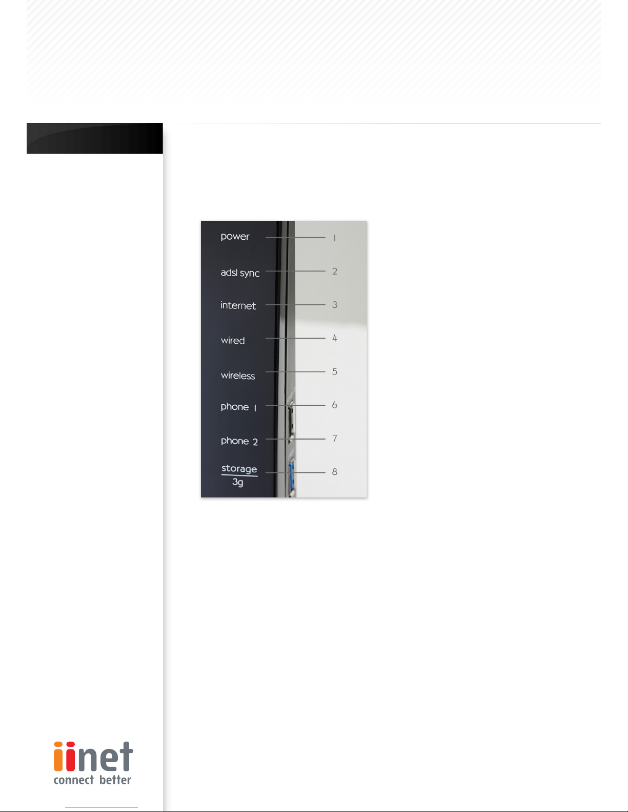
Front Panel
Power LED
When you apply power to the router or restart it, a
short period of time elapses while the router boots
up. When the router has completely booted up,
the Power LED becomes a SOLID light, indicating
the router is ready for use.
Off - Router is off
Orange - Router is booting
Blue - Router is on and ready for use
ADSL SYNC LED
The ADSL LED will light up yellow indicating no ADSL
sync. Once line sync is established the LED will light
up blue.
Off - No ADSL connection
Orange - Negotiating connection/No ADSL
sync
On - ADSL link is up and connected
1.
•
•
•
2.
•
•
•
Internet LED
The Internet LED shows you when the router
is connected to the Internet. If the LED is off
or yellow the router is NOT connected to the
Internet.
Off – Not connected to Internet
Orange – The router is not connected
to the internet or a problem
has been detected.
On – Connected to internet
LAN Status LED
When a computer is properly connected to the
LAN port on the rear of the router, the LED shown
here will light. A solid light means a computer or
a network-enabled device is connected. When
information is being sent over the port, the LED
blinks rapidly.
Off - Your computer is not connected
On - Your computer is connected
Wireless Status LED
The Wireless status LED shows you when the
router’s wireless is enabled.
On - Wireless enabled
Orange - Solid, the router has detected a
problem with a client connecting
to the wireless
Off - Wireless is disabled
6 & 7. Phone Status LED 1-2
The phone lights indicate whether VoIP account
one or two has successfully registered on the
network.
On - VoIP registered successfully
Orange - Solid, the router has detected a
problem registering your VoIP
account on the network
Off - No VoIP activity
Storage/3g
When a USB mass storage device is connected
to this USB Port, this light will illuminate to inform
you the attached storage device is ready for use.
This USB port also accepts a 3g wireless modem
service.
On – Attached USB Mass Storage or
3g Device connected and ready
for use
Off – No attached USB Mass Storage
or 3g Device
3.
•
•
•
4.
•
•
5.
•
•
•
•
•
•
8.
•
•
Note
on Side Panel Ports:
The router has an
aforementioned USB/3g
port labelled ‘3g/storage’
along with a USB charge
port.
The charge port is able
to charge devices which
use a USB connection,
such as iPods, etc.
Chapter 3 : Knowing BoB
TM
Knowing your BoBTM - 4 port integrated wireless router
Page 5
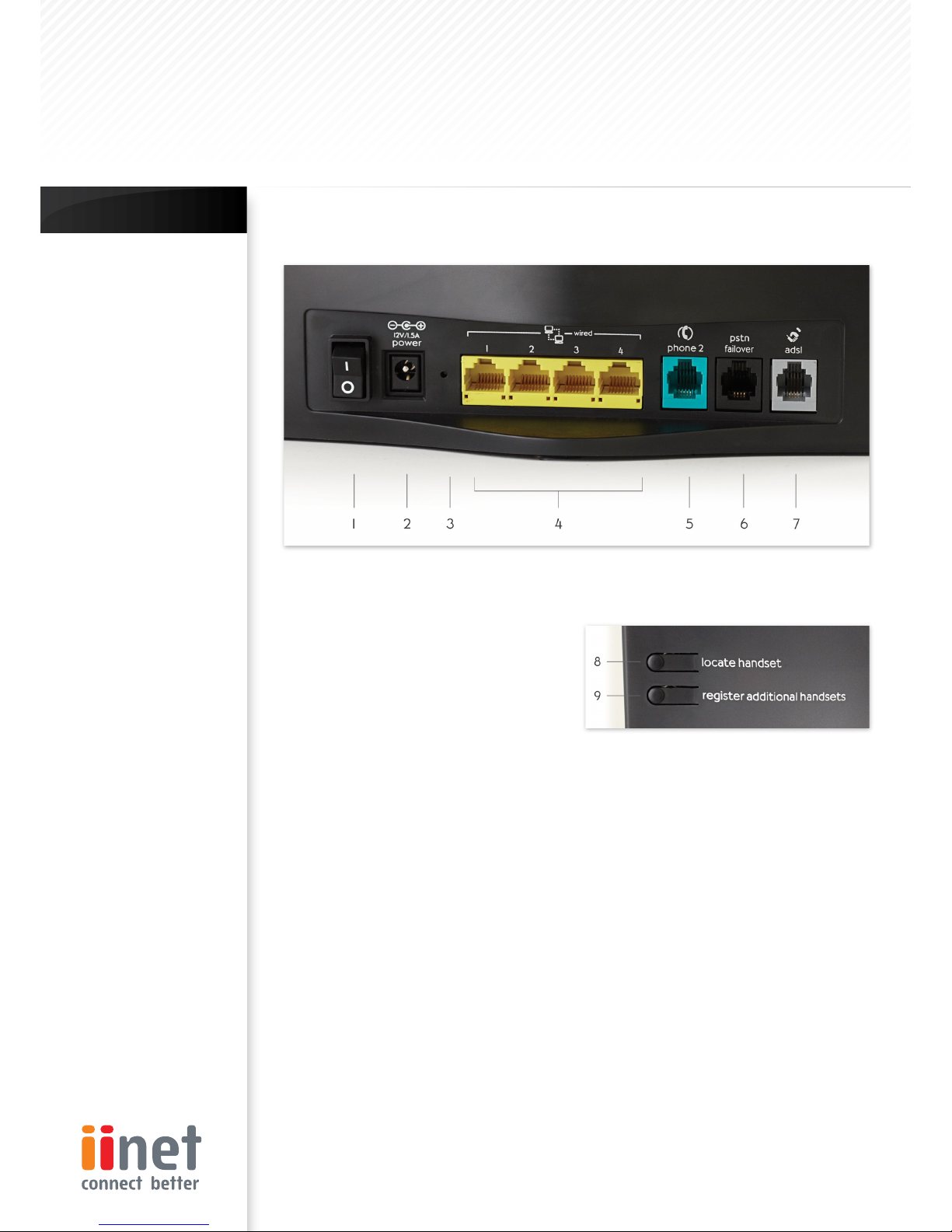
Back Panel
Chapter 4 : Connection & Configuration
Connect & Configure your BoB
TM
Power Switch
The power switch allows you to switch on or off
the router. Once you have connected the power
plug, f lip the switch to ON (‘1’) to power on the
router.
Power Plug
Connect the included 12V 1 5A DC power supply to
this inlet. Using the wrong type of power adapter
may cause damage to your router.
Reset Button
Resetting the Router
Push and hold the Reset button for one second
then release it. When the power light becomes
solid again the reset is complete.
Restoring the Factory Defaults
Push and hold the Reset button for ten seconds
then release it. When the power light becomes
solid again the restore is complete.
LAN Ports
The Ethernet port is RJ45, 10/100 auto-negotiation.
Connect your net work-enabled computers or any
networking devices to this port.
Phone Two Port
Phone Port connects to standard analogue
telephone set or fax machine.
PSTN Failover Port
The Optional RJ-11 port is for connection to your
PSTN (Home Phone) line to provide Normal Phone
call backup for when VoIP is unavailable or not
required.
1.
2.
3.
•
•
4.
5.
6.
ADSL Line
This port is for connection to your ADSL line
Connect your ADSL line to this port.
Locate handset (if installed)
Press this button to signal the BoBTM handset to
ring, allowing you to easily find its current location
Useful if you have lost the handset.
Register additional handsets
Allows you to register additional DECT compliant
handsets to your router. A total of 5 DECT
handsets can be registered to your router at any
one time.
7.
8.
9.

Page 6
Step 1. Find a suitable location
Your BoBTM - 4 port integrated wireless router can be
positioned at any convenient location in your office
or home where there is easy access to a phone jack
and power point nearby. No special wiring or cooling
requirements are needed and there is no necessity to
keep the unit connected directly to a computer.
You should, however, comply with the following
guidelines:
Keep the router away from any heating devices
Do not place the router in a dusty or wet
environment
You should also remember to turn off the power,
remove the power cord from the outlet, and keep
your hands dry when you install the router.
Step 2. Connect the ADSL Line
Phone line configuration
Run a standard telephone cable from the wall jack
providing ADSL service to the RJ-11 (‘ADSL’) port on
your router. When inserting an ADSL RJ-11 plug, be
sure the tab on the plug clicks into position to ensure
that it is properly seated. If you are using a splitter
less ADSL service, be sure you add low-pass filters
between the ADSL wall jack and your telephones
(these filters pass voice signals through but filter data
signals out).
If more than 4 connections of any kind (i e faxes,
phones, modems etc) are to be used you will need to
get a central splitter.
Step 3. Attach to your network
using Ethernet cabling
The LAN ports on the router auto-negotiates the
connection speed to 10 Mbps Ethernet or 100 Mbps
Fast Ethernet, as well as the transmission mode to
half duplex or full duplex.
Use twisted-pair cabling to connect any of the LAN
ports on the router to an Ethernet adapter on your
PC. Otherwise, cascade the LAN port on the router
to an Ethernet hub or switch, and then connect your
PC or other network equipment to the hub or switch.
When inserting an RJ-45 connector, be sure the tab
on the connector clicks into position to ensure that it
is properly seated.
Warning: Do not plug a phone jack connector into an
RJ-45 port. This may damage the router. Instead, use
only twisted-pair cables with RJ-45 connectors that
conform to Australian standards.
•
•
Step 4. Connect the power
adapter
Plug the power adapter into the power socket on
the rear panel of the router, and the other end into a
power outlet.
Check the power indicator on the front panel
is lit. If the power indicator is not lit, refer to
‘Troubleshooting’.
In case of a power failure, the router will automatically
restart and begin to operate once the power is
restored.
At this time we have now completed connecting the
router and may now move to the actual configuration
of your connection.
*Time needed to obtain line sync will vary depending
on various factors such as line noise and attempted
sync speed.
Notes:
Use 100-ohm shielded
or unshielded twisted-
pair cable with RJ-45
connectors for all
Ethernet ports. Use
Category 3, 4, or 5
for connections that
operate at 10 Mbps,
and Category 5 for
connections that
operate at 100 Mbps.
Chapter 4 : Connection & Configuration
Connect & Configure your BoB
TM

Page 7
Step 1. How to log into the router
After you have configured TCP/IP on a client
computer, use a web browser to configure the router.
The router can be configured by any Java-supported
browser such as Internet Explorer 5.0 or above. Using
the web management interface, you may configure
the router and view statistics to monitor network.
To access the router’s management interface, enter
the IP address of the router in your web browser: 10.1.1.1
Note: If you are unable to access this web
page please look at the IP setup section of the
Troubleshooting section at the back of this manual.
Type in ‘admin’ as the password and click login. NOTE:
Password is case sensitive.
ISP Settings
Please collect the following information from your ISP
before setting up the router:
ISP account user name and password
Protocol, encapsulation and VPI/VCI circuit numbers
DNS server address
IP address, subnet mask and default gateway (for
fixed IP users only)
•
•
•
•
Step 2. Navigating the web
browser interface ISP account user
name and password
The router’s management interface consists of a
Setup Wizard and an Advanced Setup section.
Setup Wizard: Use the Setup Wizard to quickly set up
the router.
Advanced Setup: Advanced Setup supports more
advanced functions like hacker attack detection, IP
and MAC address filtering, virtual server setup, virtual
DMZ host, as well as other functions.
Note: If you would like to add any additional functions
to your router please view the Advanced Setup
table of contents in order to find the correct setup
method.
Making Configuration Changes
Configurable parameters have a dialog box or a dropdown list. Once a configuration change has been
made on a page, most of the times you will need
to click the ‘SAVE SETTINGS’ or ‘NEXT’ button at the
bottom of the page to enable the new setting unless
there is an ‘ADD’ button for instance.
Note: To ensure proper screen refresh after a
command entry, be sure that Internet Explorer 5.0
and above is configured as follows: Under the menu
Tools/Internet Options/General/Temporary Internet
Files/Settings, the setting for ‘Check for newer
versions of stored pages’ should be ‘Every visit to the
page.’
Chapter 5 : Advanced Setup
BoBTM Advanced Setup Method
Page 8
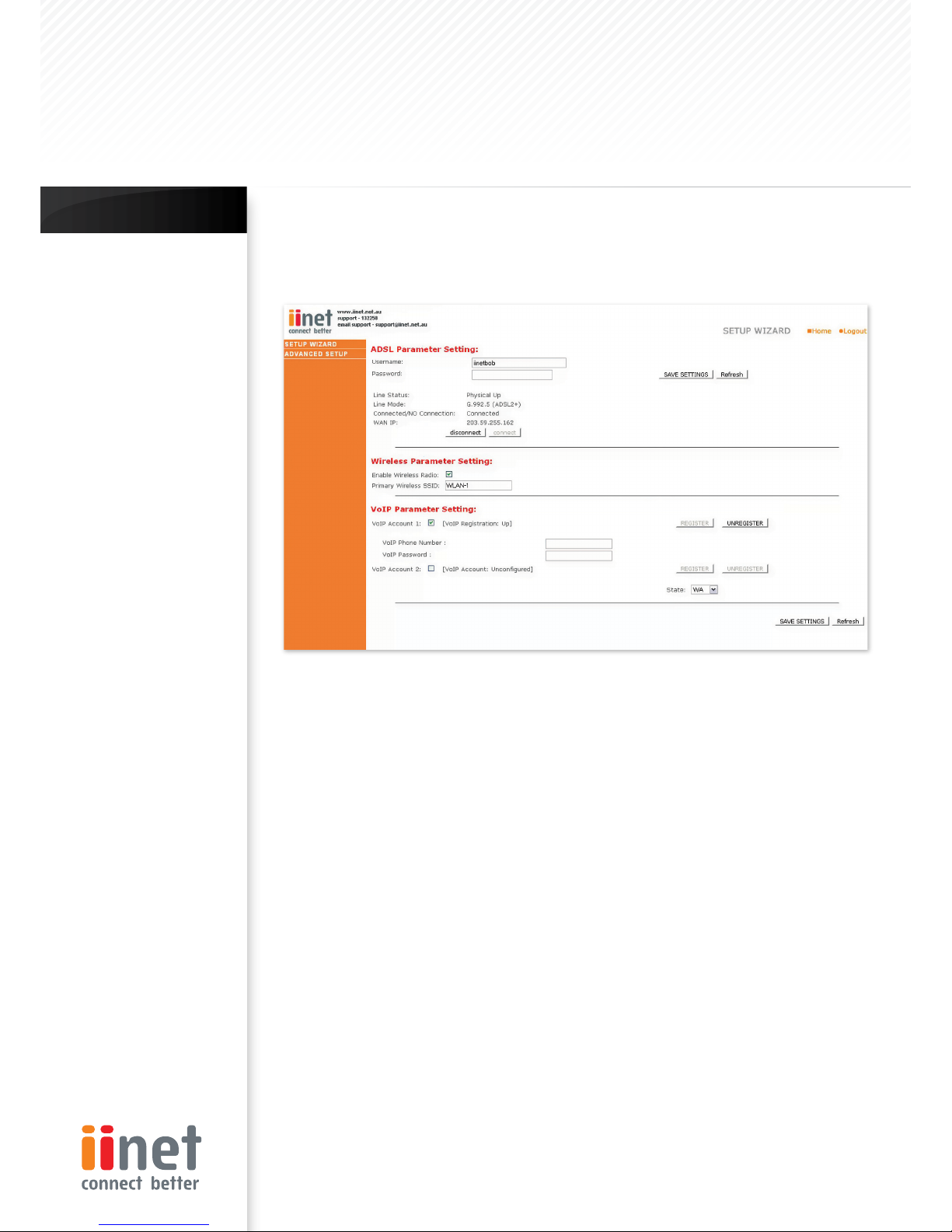
Step 3. Using Setup Wizard
This page allows you to quickly setup basic settings of the router to get you connected quickly. After making a
change, click on the save settings button on the screen to apply the changes.
Note:
VoIP port 1 is the BoB™ handset
which slots into the front
of the router or any DECT-
compatible handset s you have
registered to the router.
VOIP Parameter Setting
User Name: Enter your VoIP account user name for
your ISP
Password: Enter your VoIP account password for your
ISP
ADSL Parameter Setting
User Name: Enter your internet account user name for
your ISP
Password: Enter your internet account password for
your ISP
Wireless Parameter Setting
Enable Wireless Radio: Enable or disable the routers
wireless function.
Primar y Wireless SSID: Change the routers primary
SSID (wireless name).
VOIP Parameter Setting
Firstly you need to tick one of the VoIP account
boxes. For instance if you wish to use VoIP port 2
on the back of the router then tick the box for VoIP
account 2. Then you must enter your VoIP account
details and click on ‘SAVE SETTINGS’.
Phone Number: Enter your VoIP account phone
number from your ISP.
Password: Enter your VoIP account password for
your ISP.
Register: Click to register your VoIP account to be
ready for use.
Unregister: Un-register your VoIP account, so that
you can use it on another VoIP port or device.
Advanced Setup Method
Clicking the Home icon returns you to the home
page. The Main Menu links are used to navigate to
other menus that display configuration parameters
and statistics.
Making Configuration Changes
Configurable parameters have a dialog box or a dropdown list. Once a configuration change has been
made on a page, click the ‘SAVE SETTINGS’ button at
the bottom of the page to make the new settings
active.
•
•
•
•
Chapter 5 : Advanced Setup
BoBTM Advanced Setup Method
Page 9
The router’s advanced management interface contains 15 main menu items as described in the following list.
Note:
To ensure proper
screen refresh after a
command entry, check
that Internet Explorer
5.0 is configured as
follows: Under the menu
Tools/Internet Options/
General/Temporary
Internet Files/Settings,
the setting for ‘Check for
newer versions of stored
pages’ should be ‘Every
visit to the page.’
Commonly Requested Features
Noted in this section is a quick reference guide to
the most commonly requested advanced features
and should save you the time of needing to read the
entire section for the necessary features you are
interested in.
Setting up Wireless (Page 44)
This section will explain the basics of turning on the
Wireless Functions in your router, if you should require
this service it is also suggested you look into the
Setting up Wireless Security area as well.
Setting up Wireless Security (Page 44)
This section describes the 2 forms of Wireless security
available and allows you to choose either or both
types of security in order to protect your network
from outside access.
Option 1: MAC address filtering (Page 21)
MAC Address Filtering uses a unique code that
each computer has in order to create a list of
computers that will be allowed onto your network.
Option 2: Wireless encryption (Page 22)
Wireless encryption uses a code much like a secret
password in order to ensure only those computers
which know the password are able to access your
network.
•
•
Setting up VoIP (Page 44)
This section will guide you through the basics of
setting up your VoIP service on your network
Setting/Adjusting Quality of Service (Page 50)
If you are having problems with the quality of your
Voice service due to large amounts of network traffic
you may adjust your Quality of Service in this section.
Port Forwarding (Page 27)
Some programs will require you to direct certain port
numbers to your computer in order to bypass the
built in Firewall.
Should there be any further features within the
product you would like to use please find a more
extensive list on the next page.
Chapter 5 : Advanced Setup
BoBTM Advanced Setup Method

Page 10
Menu Description
System (Page 11)
Within the System menu you can:
Set the local time and Time zone as well as Time
Sync Server.
Set the password for administrator access.
Enable remote management and set the IP
address of a PC that will be allowed to access
Router remotely.
The IP address of a Domain Name Server.
WAN (Page 13)
ATM PVC specifies the Internet connection
setting for an ATM (Asynchronous Transfer Mode)
Framework WAN, this service is used primarily in
corporate environments and we would suggest
contacting your corporate administrator in order to
setup these features.
MAC Address Cloning can also be performed in this
section complete the Internet connection should
it be required by your internet service provider in
order to complete the Internet connection.
LAN (Page 17)
The LAN menu itself has a number of special fields in
which you can configure information about your Local
Area Network like those functions noted below:
LAN IP Address Settings.
Subnet Mask settings.
DCHP Server Control.
VLAN Port routing.
The LAN Menu also has 2 sub-menus:
VLAN
This menu allows you to set the VLAN rules for
the other ports and should only be accessed by
experienced professionals.
DHCP Client Lists
This menu shows you a list of all computers
currently connected to your network along with
their host name and other details.
•
•
•
•
•
•
•
•
•
•
1.
2.
Wireless (Page 19)
The Wireless Menu allows you to turn on/off the
wireless features on your router as well as having 4
sub-menus:
Channel & SSID
This area includes the most basic of router
functions and allows you to give a unique name
to your network as well as allowing you to change
the channel your wireless is running on in case it is
accidentally sharing the same channel as another
wireless appliance in the area.
Access Control
Access Control or MAC address filtering as it is also
known is an additional level of security which allows
you to specify which computers are able to log
into the network via their unique ‘MAC Address’.
Security
The Security menu allows you access to the other
form of Wireless Security known as Encryption. This
works by using a numerical code as a key to your
network.
WDS
WDS stands for Wireless Distribution System and is
designed to allow you to add access points to your
network. These work as a relay station to extend
the range of your network.
NAT (Page 25)
Shares a single ISP account with multiple users, sets
up Port forwarding.
Route (Page 30)
Sets routing parameters and displays the current
routing table. A route determines the way in which
the data travels through the network.
Firewall (Page 33)
Configures a variety of security and specialized
functions including: Access Control, URL blocking,
Internet access control scheduling, Intruder
detection, and DMZ.
SNMP (Page 41)
Community string and trap server setting. SNMP
(Simple Network Management Protocol) is used
by network administrators to manage attached
network devices.
ADSL (Page 42)
Sets the ADSL operation type and shows the ADSL
status.
1.
2.
3.
4.
Chapter 5 : Advanced Setup
BoBTM Advanced Setup Method
Page 11
VoIP (Page 44)
Configures VoIP settings for the router, this section
involves extensive and detailed settings. Please
read the entire section carefully before attempting
any changes.
UPnP (Page 49)
Allows you to enable or disable the Universal Plug
and Play function. UPnP is designed to allow users
seamless Internet operation without the need to
open any ports in the firewall.
QoS (Page 50)
Allows you to optimize voice quality by prioritizing
voice over data traffic. QoS (Quality of Service) can
be set to prioritize traffic for many features such as
VoIP, VPN, nominated IP Addresses and ports etc.
DDNS (Page 52)
DDNS (Dynamic Domain Name Server) allows you
to host services on the internet via a web address.
For example it would allow you to host a web
page or email server even with a dynamic WAN
IP Address. In order to use this function you may
need to purchase additional services like a Domain
name from a service provider. This router supports
DynDNS and TZO.
USB (Page 53)
You can plug-in your USB hard drive or memory
stick and share these resources on your home
network.
Tools (Page 55)
Contains options to back up and restore the
current configuration, restore all configuration
settings to the factory defaults, update system
firmware, or reset the system each under its own
menu.
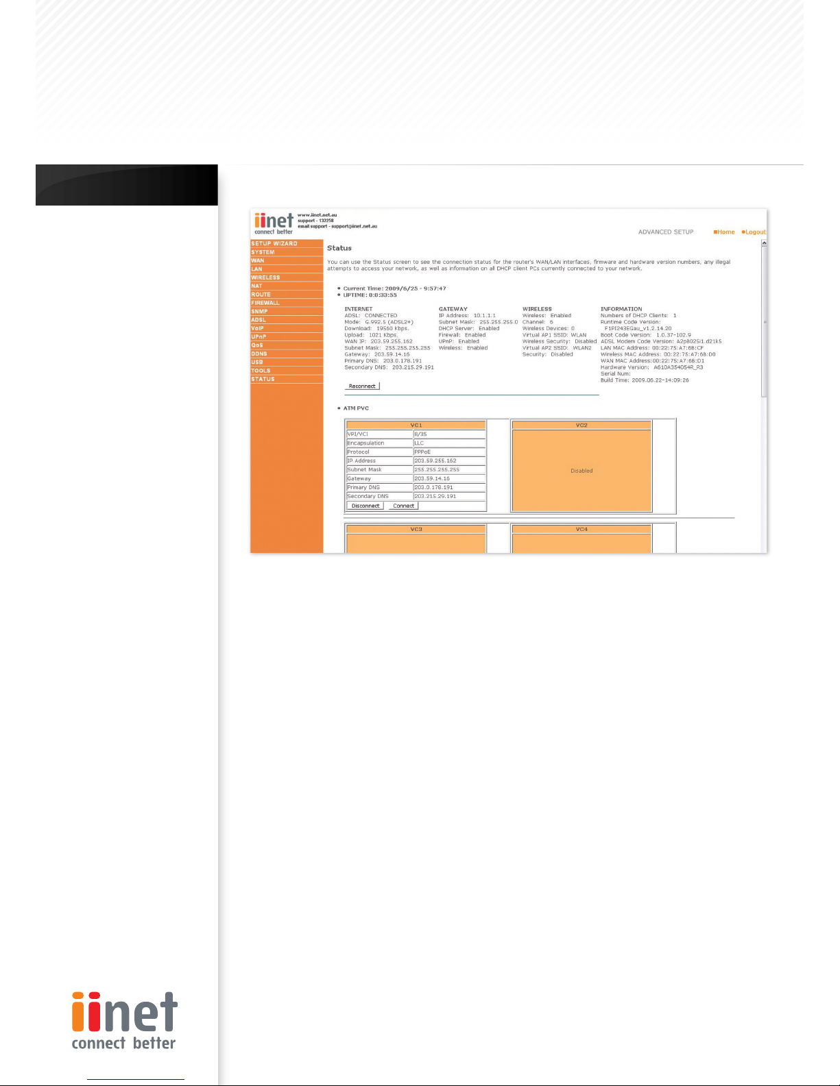
Status (Page 43)
Provides WAN connection type and status,
firmware and hardware version numbers, system
IP settings, as well as DHCP, NAT, and firewall
information.
Displays the number of attached clients, the
firmware versions, the physical MAC address for
each media interface, and the hardware version
and serial number.
Shows the security and DHCP client log.
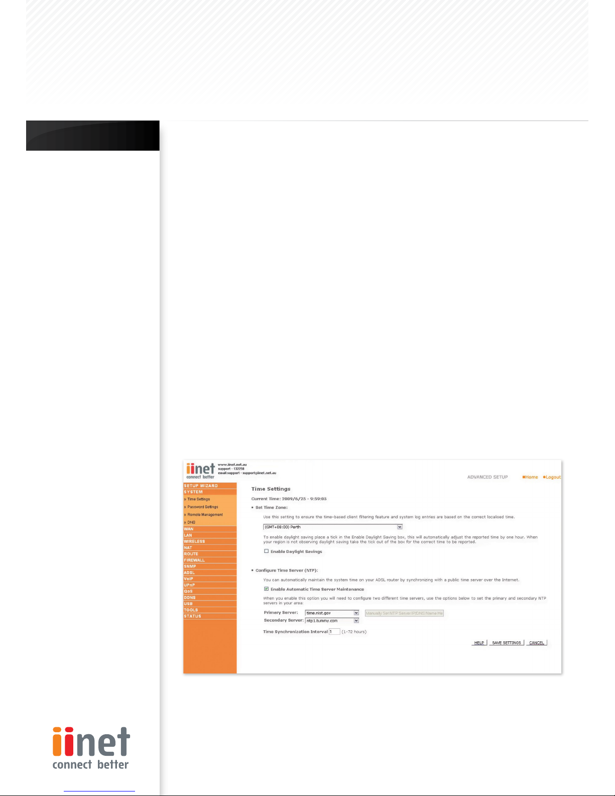
System Time Settings
Set the time zone and time server for the router. This information is used for log entries and client access
control.
Check ‘Enable Automatic Time Server Maintenance’ to automatically maintain the router’s system time
by synchronizing with a public time server over the Internet. Then configure two different time servers by
selecting the options in the Primary Server and Secondary Server fields.
Chapter 5 : Advanced Setup
BoBTM Advanced Setup Method
Page 12
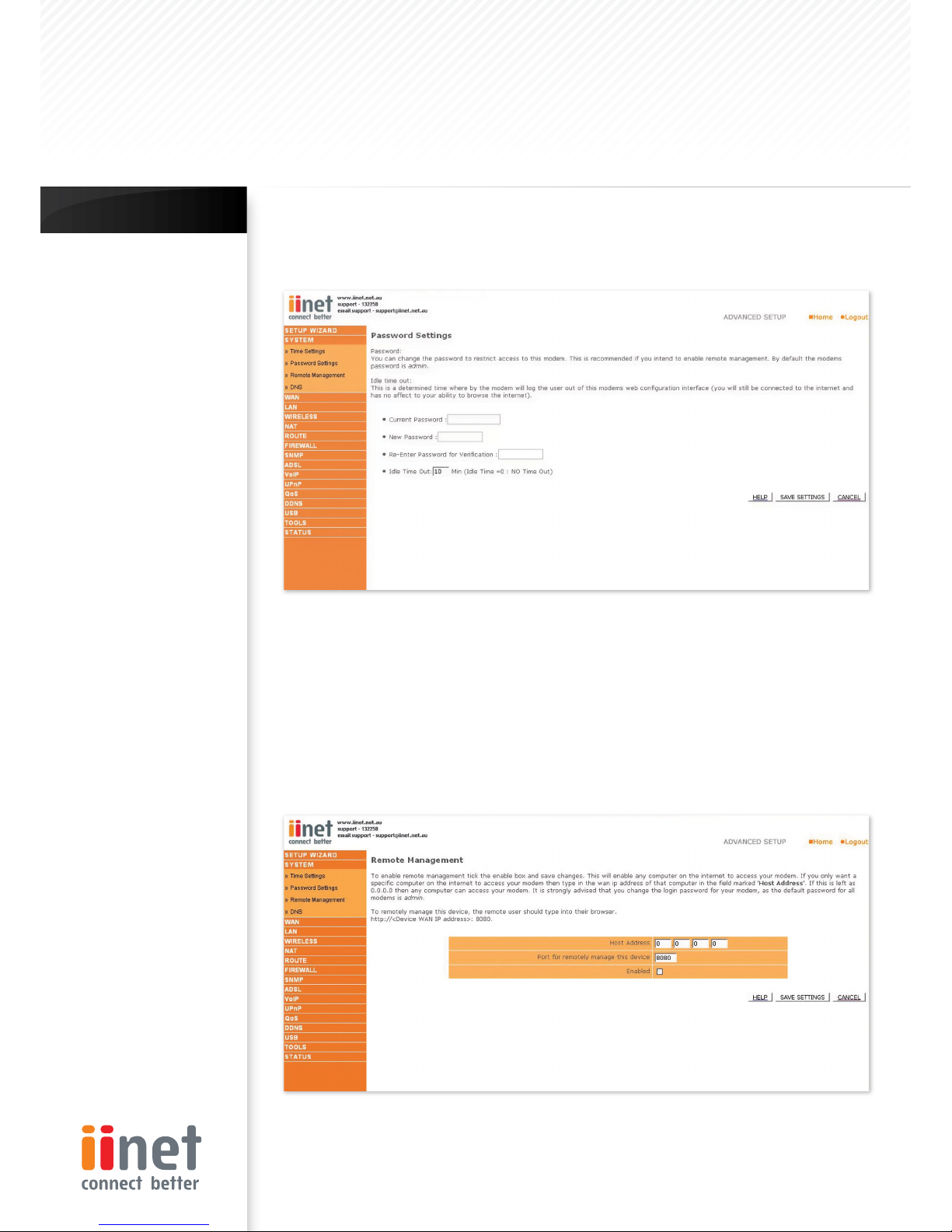
Password Settings
Use this page to restrict access based on a password.By default, the password is ‘admin’.
Passwords can contain from 3 to 12 alphanumeric characters which are case sensitive.
Enter a maximum Idle Time Out (in minutes) to define a maximum period of time an inactive login session will be
maintained. If the connection is inactive for longer than the maximum idle time, it will be logged out, and you
will have to login to the web management system again (Default: 10 minutes).
Remote Management
By default, management access is only available to users on your local network. However, you can also manage
the router from outside your network via remote management by checking the Enabled check box. You can
set a HOST ADDRESS, which will only allow that computer to use remote management. The port field should be
left as the default setting of 8080 unless you need to change it. After any changes are made you must click on
‘Save Settings’ to apply them.
Note:
If your password is lost,
or you cannot gain
access to the user
interface, press the
reset button (colored
blue) on the rear panel
(holding it down for
at least 20 seconds)
to restore the factory
defaults (by default the
password is ‘admin’) .
Chapter 5 : Advanced Setup
BoBTM Advanced Setup Method
Page 13
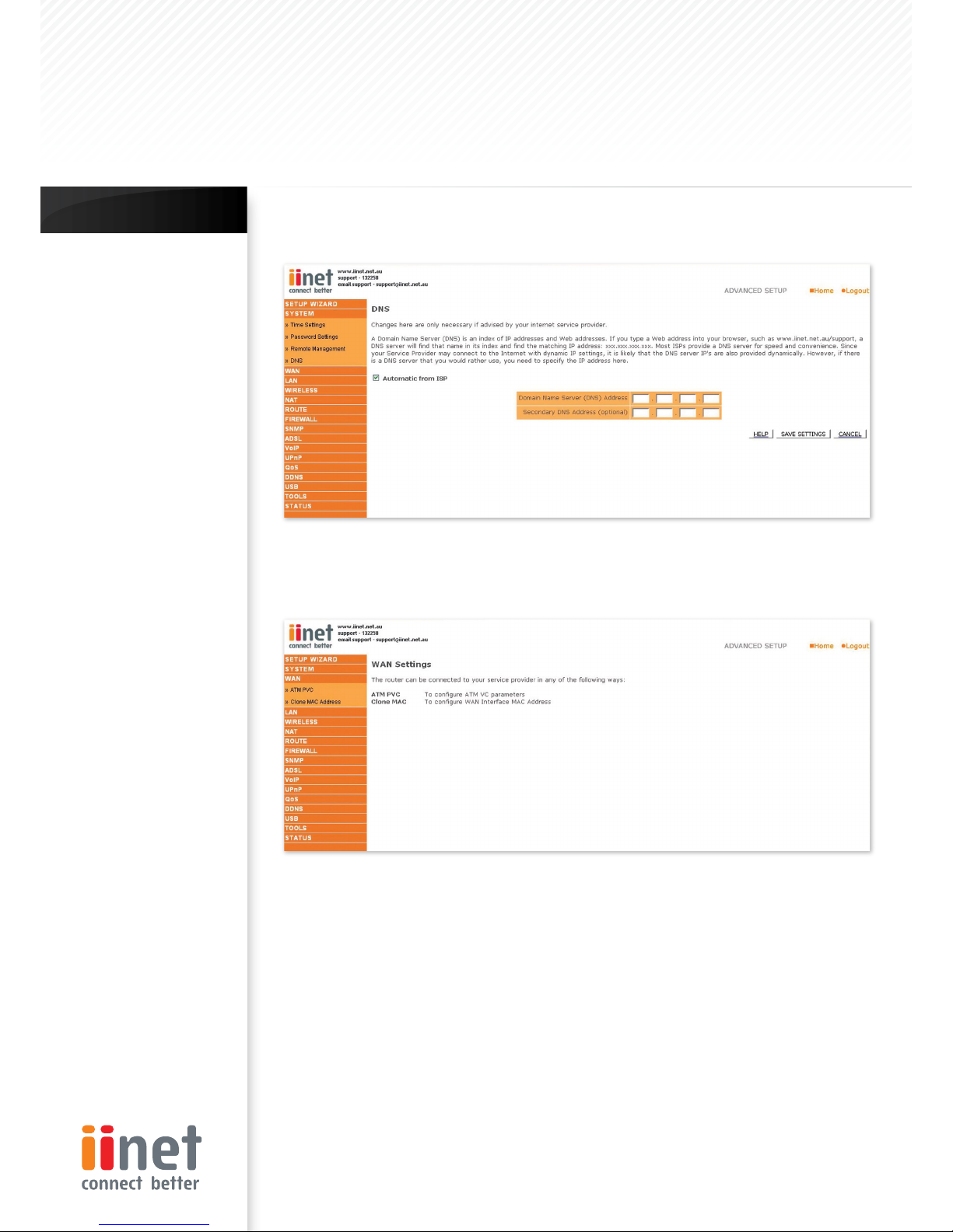
DNS
Domain Name Servers are used to map a domain name (e.g. www.somesite.com) to the equivalent numerical
IP address (e.g. 64.147.25.20). Your ISP should provide the IP address of one or more Domain Name Servers. Enter
those addresses on this page.
WAN
Specify the WAN connection parameters provided by your Internet Service Provider (ISP). The router can be
connected to your ISP in one of the following ways:
ATM PVC
Clone MAC
•
•
Note:
If you check ‘Enabled’
and specify an IP address
of 0.0.0.0, any host can
manage the router.
For remote
management via a WAN
IP address you need
to connect using port
8080.Simply enter WAN
IP address followed by
:8080 in the address
field of your web
browser, for example,
http://212.120.68.20:8080.
This applies unless you
change the port setting,
in which case you need
to substitute the 8080
for whatever port you
have assigned.
Chapter 5 : Advanced Setup
BoBTM Advanced Setup Method
Page 14
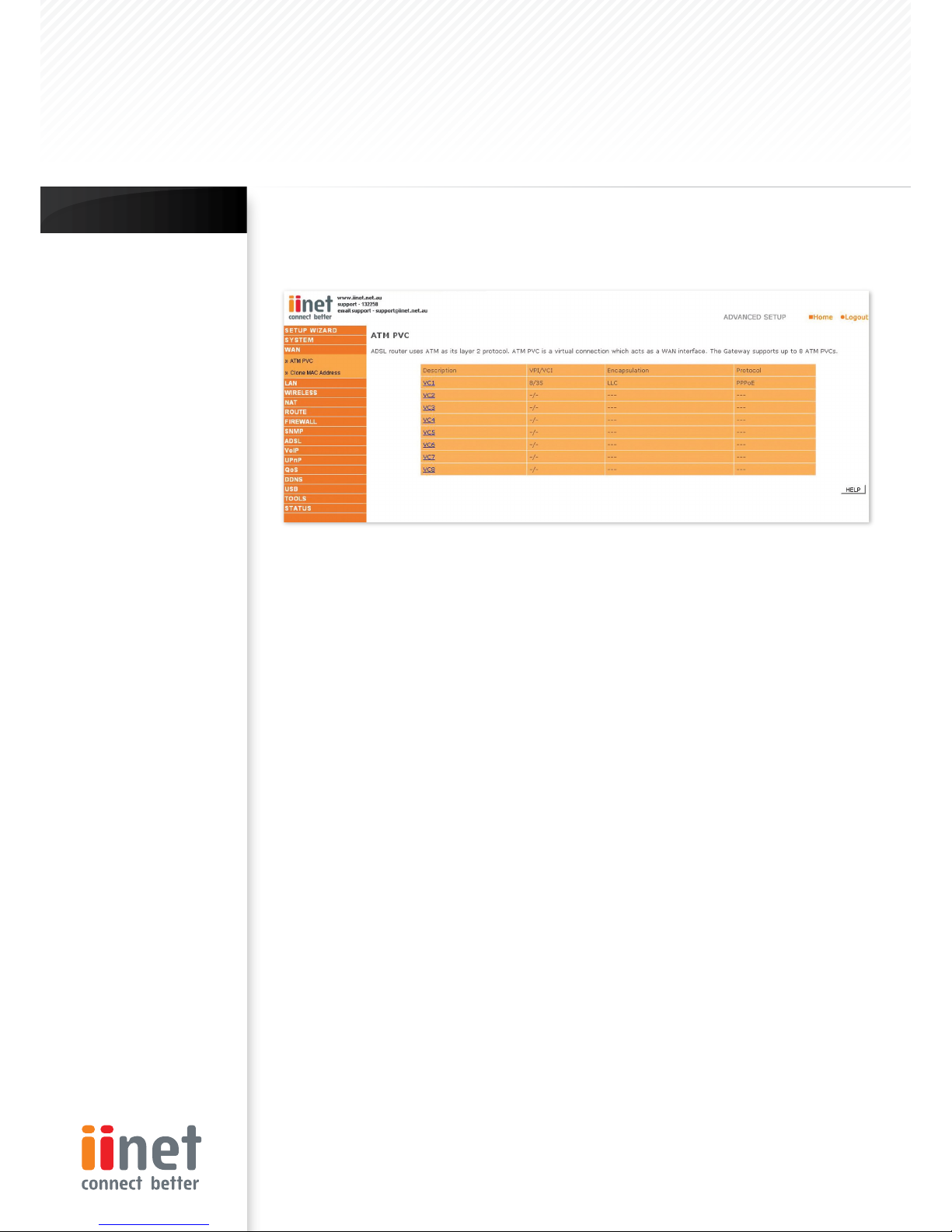
ATM PVC
The router uses ATM as its WAN interface. Click on each ATM VC for WAN configuration.
Parameter Description
Description: Click on the VC to set the values for the connection.
VPI/VCI: Virtual Path Identifier (VPI) and Virtual Circuit Identifier (VCI).
Encapsulation: Specif ies how to handle multiple protocols at the ATM transport layer.
VC-MUX: Point-to-Point Protocol over ATM Virtual Circuit Multiplexer (null encapsulation) allows only one
protocol running per virtual circuit with less overhead.
LLC: Point-to-Point Protocol over ATM Logical Link Control (LLC) allows multiple protocols running over one
virtual circuit (using slightly more overhead).
Protocol: Protocol used for the connection.
•
•
Chapter 5 : Advanced Setup
BoBTM Advanced Setup Method
Page 15
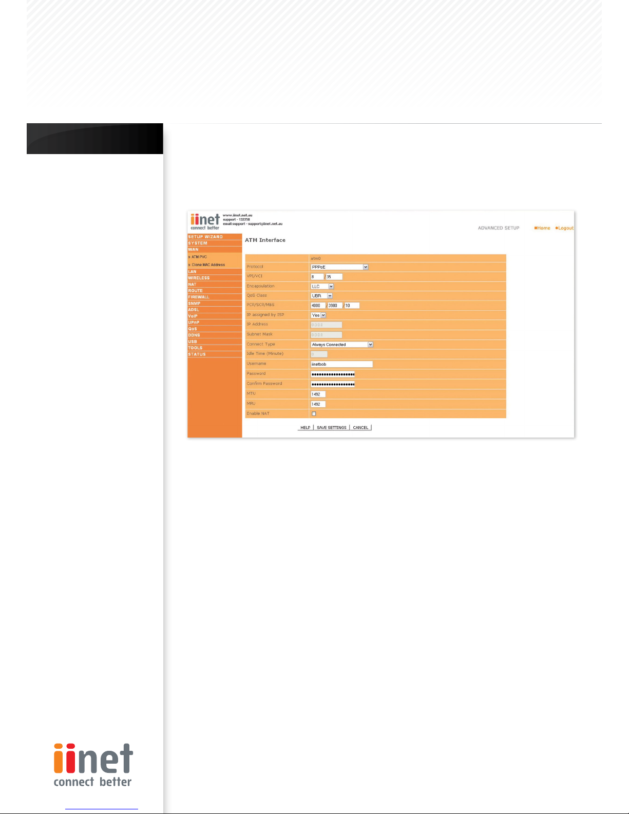
ATM Interface
Clicking on the ATM VC brings up the following screen. The router uses ATM as its WAN interface. Protocols
including 1483 Routing, 1483 Bridging, MAC Encapsulated Routing (MER), PPPoA and PPPoE with LLC-SNAP and VCMUX encapsulations are supported for each ATM PVC.
When you have finished entering your connection parameters, click ‘SAVE SETTINGS’. You can verify that you
have established an ADSL connection by clicking ‘Status’ at the bottom of the left-hand menu.
See below for a description of the parameters.
Parameter Description
Protocol
Disable: Disables the connection
1483 Bridging: Bridging is a standardized layer
2 technology. It is typically used in corporate
networks to extend the physical reach of a single
LAN segment and increase the number of stations
on a LAN without compromising performance.
Bridged data is encapsulated using the RFC1483
protocol to enable data transport. Please note
that setting the router to bridged mode disables
all advanced features such as VoIP, Firewall, and
QoS, etc
PPPoA: Point-to-Point Protocol over ATM is a
method of encapsulating data for transmission to
a far point
1483 Routing: 1483 Routing allows a simple, low-cost
connection to the Internet via a standard Ethernet
port. The router looks up the network address for
each packet seen on the LAN port. If the address
is listed in the routing table as local, it is filtered.
If the address is listed under the ADSL port, it is
forwarded. Or if the address is not found, then it is
automatically forwarded to the default router (i.e.,
the router at the head end)
1.
2.
3.
4.
PPPoE: Point-to-Point over Ethernet is a common
connection method used for xDSL
MAC Encapsulated Routing: If your ADSL service
is a Bridged mode service and you want to share
the connection to multiple PC’s, please select MAC
Encapsulated Routing. MER is a protocol that allows
you to do IP routing with NAT enabled
VPI/VCI
Virtual Path Identifier (VPI) and Virtual Circuit
Identifier (VCI). Data flows are broken up into fixed
length cells, each of which contains a Virtual Path
Identifier (VPI) that identifies the path between
two nodes, and a Virtual Circuit Identifier (VCI) that
identifies the data channel within that virtual path.
Each virtual circuit maintains a constant flow of cells
between the two end points. When there is no data
to transmit, empty cells are sent. When data needs
to be transmitted, it is immediately inserted into the
cell flows.
5.
6.
Chapter 5 : Advanced Setup
BoBTM Advanced Setup Method
Page 16
Encapsulation
Shows the packet encapsulation type.
Packet encapsulation specifies how to handle
multiple protocols at the ATM transport layer.
VC-MUX: Point-to-Point Protocol over ATM Virtual
Circuit Multiplexer (null encapsulation) allows only
one protocol running per virtual circuit with less
overhead
LLC: Point-to-Point Protocol over ATM Logical Link
Control allows multiple protocols running over one
virtual circuit (using slightly more overhead)
QoS Class
ATM QoS classes including CBR, UBR and VBR.
PCR/SCR/MBS
QoS Parameters - PCR (Peak Cell Rate), SCR
(Sustainable Cell Rate) and MBS (Maximum Burst Size)
are configurable.
•
•
Connect Type
Sets connection mode to always connected,
automatic or manual connection.
Idle Time: Enter the maximum idle time for the
Internet connection.(in minutes) After this time has
been exceeded the connection will be terminated.
Username: Enter user name
Password: Enter password
Confirm password: Confirm Password
MTU
Leave the Maximum Transmission Unit (MTU) at the
default value (1500) unless you have a particular
reason to change it.
•
•
•
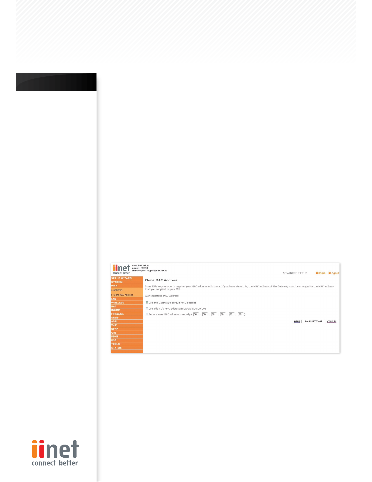
Clone MAC Address
Clicking on the Clone MAC Address brings up the following screen.
Some ISPs may require that you register your MAC address with them. If this is the case, the MAC address of the
router must be changed manually to the MAC address that you have registered with your ISP.
Chapter 5 : Advanced Setup
BoBTM Advanced Setup Method
Page 17
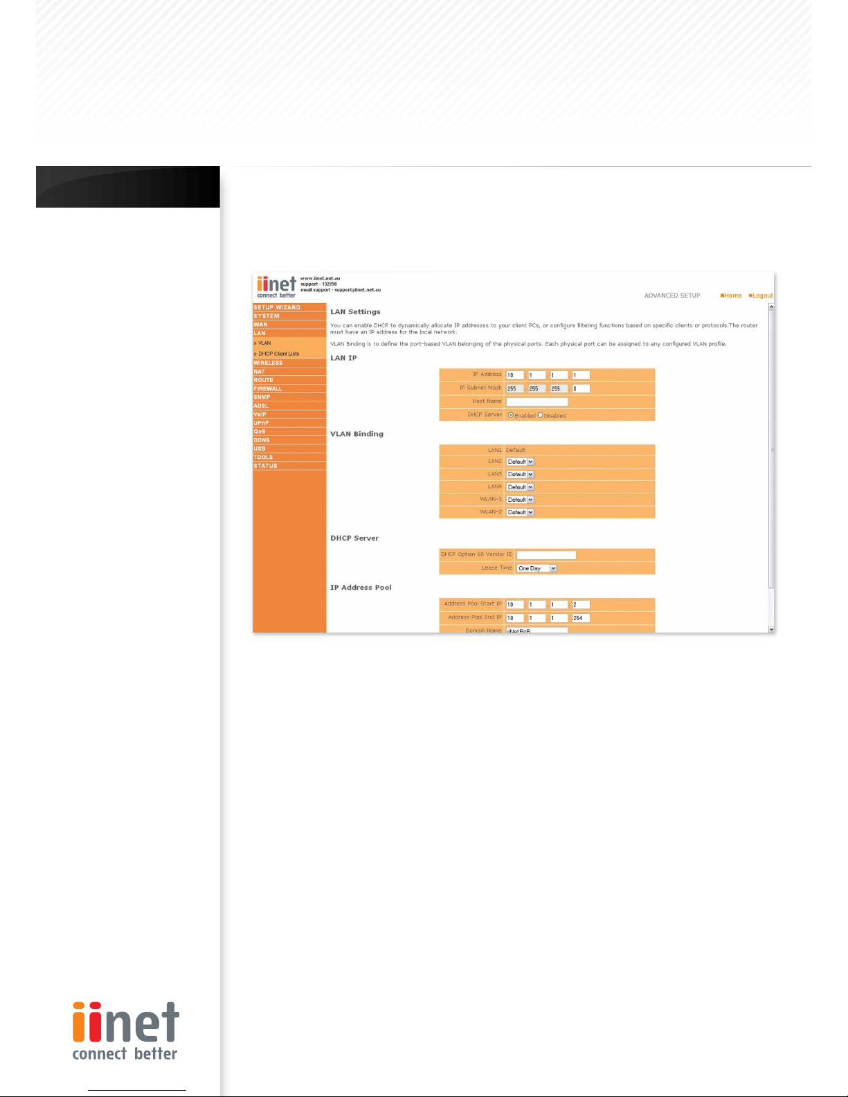
LAN
Use the LAN menu to configure the LAN IP address and to enable the DHCP server for dynamic client address
allocation.
Parameter Description
LAN IP
IP Address: The IP address of the router
IP Subnet Mask: The subnet mask of the router
Host Name: If your ISP requires a hostname specified
enter it here, otherwise leave blank
DHCP Server: To dynamically assign an IP address to
client PCs, enable the DHCP (Dynamic Host
Configuration Protocol) Server
VLAN Binding
In this section you can assign VLAN’s that you have
created in the VLAN page to certain ports such as
LAN port 1, 2, 3 or 4 and the WLAN connection. For
instance if you have created a VLAN Binding called
‘Test’, and you want anything connected to the
wireless to be on that VLAN, then you would change
the WLAN setting on this page from ‘Default’ to the
one you created called ‘Test’.
DHCP SERVER
DHCP Option 60 Vendor ID: If you wish you can
specify the Name of your DHCP Server (Optional).
Lease Time: Specify the length of time that the
DHCP will assign an IP address to a computer for.
IP Address Pool
Start IP: Specify the start IP address of the DHCP pool
Do not include the gateway address of the router in
the client address pool (see ‘TCP/IP
Configuration’). If you attempt to include the router
gateway address (10.1.1.1 by default) in the DHCP pool,
an error dialog box will appear. If you change the pool
range, make sure the f irst three octets match the
gateway’s IP address, i.e.10.1.1.xxx
End IP: Specify the end IP address of the DHCP pool.
Domain Name: If your network uses a domain name,
enter it here. Otherwise, leave this field blank
•
•
Chapter 5 : Advanced Setup
BoBTM Advanced Setup Method
Page 18
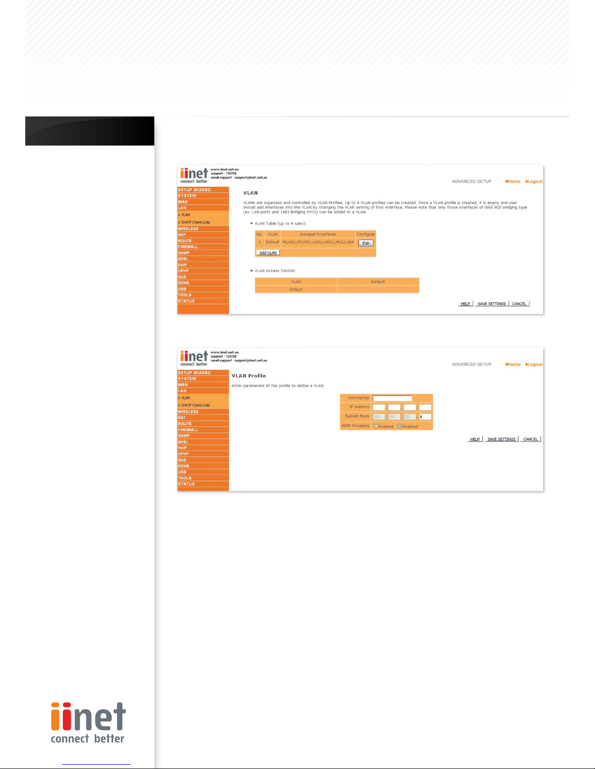
VLAN
VLAN Table: In this table you can click on the ‘ADD VLAN’ button to add a ‘VLAN’ binding or click on ‘EDIT’ to edit
an existing binding, or click on ‘DELETE’ to remove a binding.
VLAN Profile: This screen will appear if you click on
‘ADD VLAN’ or ‘EDIT’ from the VLAN page.
Description: detailed description of the VLAN.
IP Address: IP address of the VLAN virtual interface
on the gateway.
Subnet Mask: subnet mask of the VLAN virtual
interface.
NAT Domain: NAT addressing domain to define the
NAPT operation of the VLAN virtual interface. Public
means that this VLAN will be visible to the Internet.
Private means NAT is enabled to protect the subnet
from visibility to the Internet.
IGMP Snooping: enable/disable the feature to block
unnecessary IP multicast traffic f looding among VLAN
ports without the specific multicast membership. This
feature is working based on snooping IGMP Join/
Leave messages among the VLAN ports to update
the bridging forwarding database. IGMP Snooping
is extremely useful in saving bandwidth of flowspeed interfaces (ex WLAN) to improve the network
utilization.
IGMP Querier: enable/disable IGMP querying to
the VLAN virtual interface. The option is to control
whether to behave as an IGMP querier on the VLAN
bridging network If IGMP Querier option is disabled,
the router will act as an IP multicast compliant host
and send IGMP reports for its own joined IP multicast
groups.No IGMP query messages will be sent to the
specific VLAN.
Chapter 5 : Advanced Setup
BoBTM Advanced Setup Method
Page 19
VLAN Access Control:
In this table you can enable or disable the communication between the VLAN bindings by ticking (enable) or
un-ticking (disable) the corresponding name in the table.
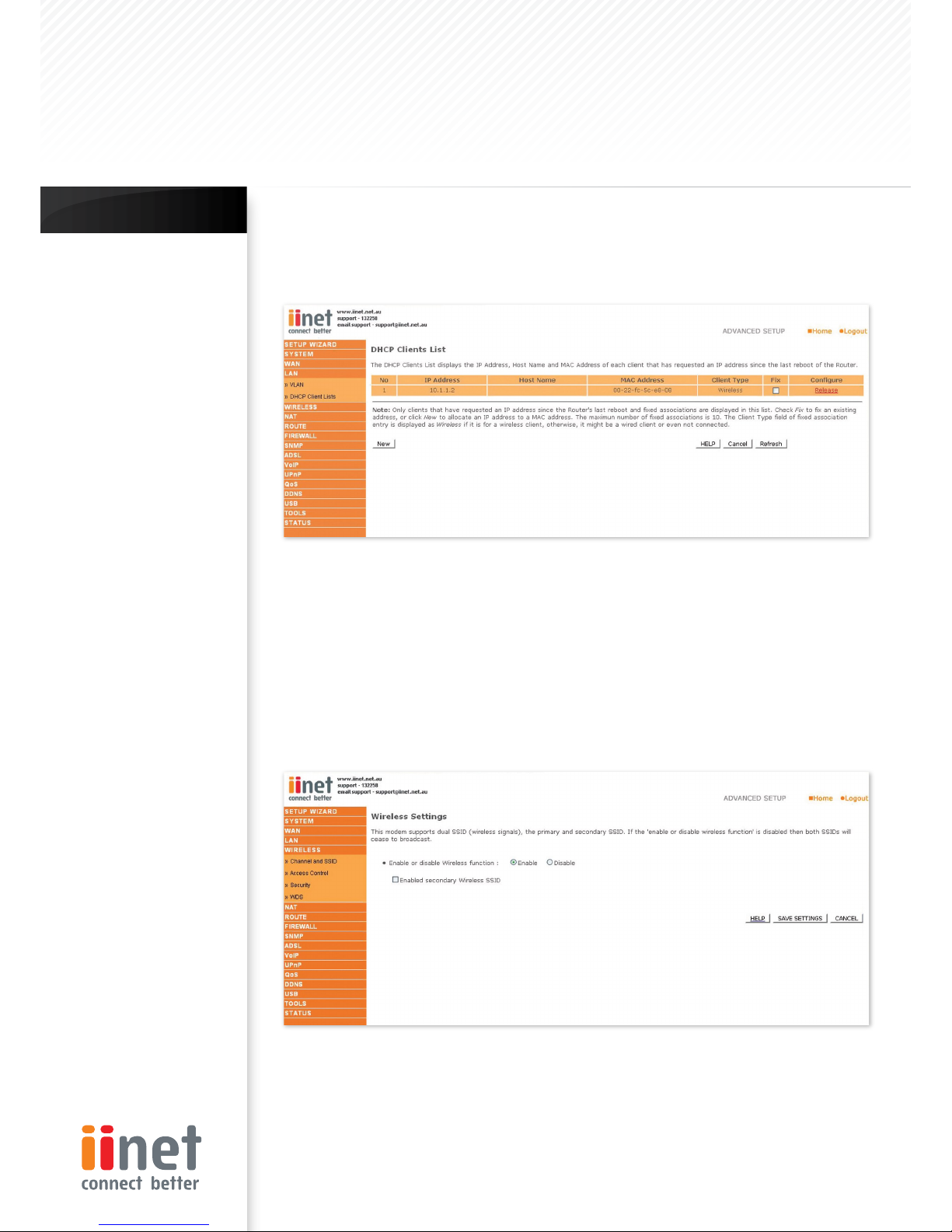
The DHCP Clients List displays the IP Address, Host Name and MAC Address of each client that has requested an
IP address since the last reboot of the Router. Check the ‘Fix’ box to have the IP address and the MAC address
linked so that the IP address will always be assigned as it is on this screen.
Wireless
The router also operates as a wireless access point,
allowing wireless computers to communicate with
each other. To configure this function, you need to
enable the wireless function, and you may also setup
the security options if needed.
Wireless Settings
Check Enable or Disable and click ‘SAVE SETTINGS’ This
will turn the wireless function on or off and enable or
disable wireless clients to connect to the router.
The router suppor ts two wireless SSID’s, to enable the
second SSID place a tick in the ‘Secondary Wireless
Module’ and click ‘SAVE SETTINGS’.
Chapter 5 : Advanced Setup
BoBTM Advanced Setup Method
 Loading...