

Belkin F5D8636V2 Users Manual
USING THE WEB-BASED ADVANCED USER INTERFACE
SECTIONSTable of Contents 1 2 3 4 5 7 8 9
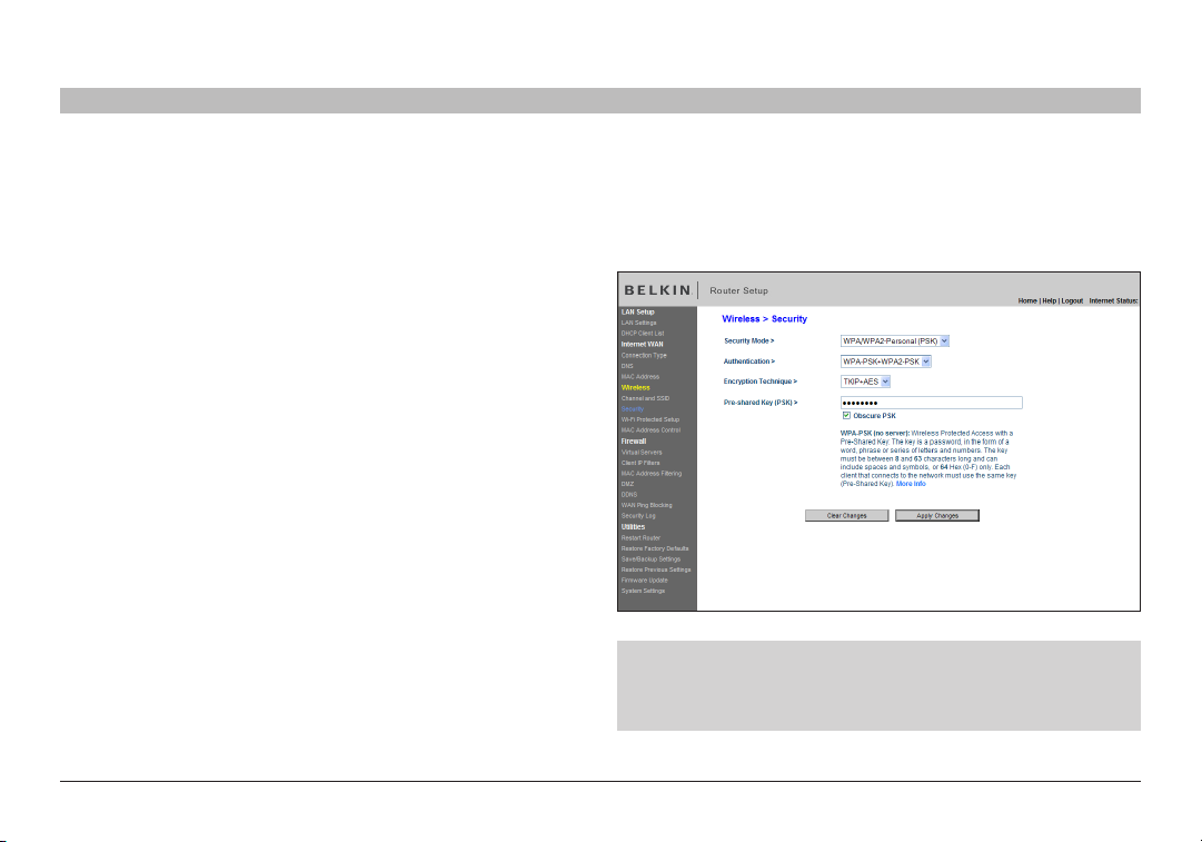
Setting WPA/WPA2-Personal (PSK)
Like WPA security, WPA2 is available in WPA2-Per sonal (PSK) mode. Typically, WPA2-Personal (PSK) is the mode that will be used in a home
environment. Please refer to the User Manual for more information about wireless security and different types of wireless security.
1. After you’ve set up your Router, go to the “Security” page under
“Wireless” and select “WPA/WPA2-Personal (PSK)” from the “Security
Mode” drop-down menu.
2. For “Authentication”, select “WPA-PSK”, “WPA2-PSK”, or “WPA-PSK +
WPA2-PSK”. This setting will have to be identical on the wireless clients
that you set up. “WPA-PSK + WPA2-PSK” mode will allow the Router to
suppor t clients running either WPA or WPA2 security.
3. For “Encryption Technique”, select “TKIP”, “AES”, or “TKIP+AES”. This
setting will have to be identical on the wireless clients that you set up.
4. Enter your pre-shared key (PSK). This can be from eight to 63
characters and can be letters, numbers, or symbols. This same key
must be used on all of the wireless clients that you set up. For example,
your PSK might be something like: “Smith family network key”. Click
“Apply Changes” to finish. You must now set all wireless clients to
match these settings.
IMPORTANT: Make sure your wireless computers are updated
to work with WPA2 and have the correct settings to get proper
connection to the Router.
6
10
N Wirel ess Modem Ro uter
48
USING THE WEB-BASED ADVANCED USER INTERFACE
SECTIONSTable of Contents 1 2 3 4 5 7 8 9
6
10
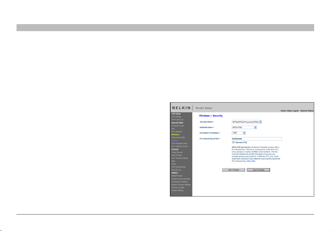
Setting WPA Security
Note: To use WPA security, your wireless network cards must be equipped with software that supports WPA. At the time this User Manual was
published, a security patch from Microsoft is available for free download. This patch works only with Windows XP.
Your Router suppor ts WPA-PSK. WPA-PSK uses what is known as a pre-shared key as the security key. A pre-shared key is basically a password
that is between eight and 39 characters long. It can be a combination of letters, numbers, or characters. Each client uses the same key to access the
network. Typically this is the mode that will be used in a home environment.
Setting WPA-PSK
1. From the “Security Mode” drop-down menu, select “WPA-PSK”.
2. For “Encryption Technique”, select “TKIP” or “AES”. This setting will
have to be identical on the clients that you set up.
3. Enter your pre-shared key. This can be from eight to 36 characters and
can be letters, numbers, or symbols. This same key must be used on
all of the clients that you set up.
4. Click “Apply Changes” to finish. You must now set all clients to match
these settings.
N Wirel ess Modem Ro uter
49
USING THE WEB-BASED ADVANCED USER INTERFACE
SECTIONSTable of Contents 1 2 3 4 5 7 8 9
6
10
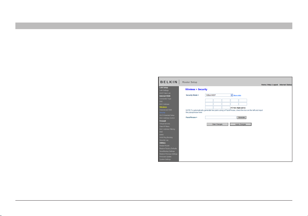
Setting WEP Encryption
Note to Mac users: The “Passphrase” option will not operate with A pple® AirPort®. To configure encryption for your Mac computer, set the encryption
using the manual method described in the next section.
1. Select “128-bit WEP” or “64-bit WEP” from the drop- down menu.
2. After selecting your WEP encryption mode, you can enter you WEP
key manually by typing in the hex WEP key manually, or you can type
a passphrase in the “PassPhrase” field and click “Generate” to create
a WEP key from the passphrase. Click “Apply Changes” to finish. You
must now set all of your clients to match these settings.
3. Encryption in the Router is now set. Each of your computers on
your wireless network will now need to be configured with the same
passphrase. Refer to the documentation of your wireless network
adapter for information on making this change.
N Wirel ess Modem Ro uter
50
USING THE WEB-BASED ADVANCED USER INTERFACE
SECTIONSTable of Contents 1 2 3 4 5 7 8 9
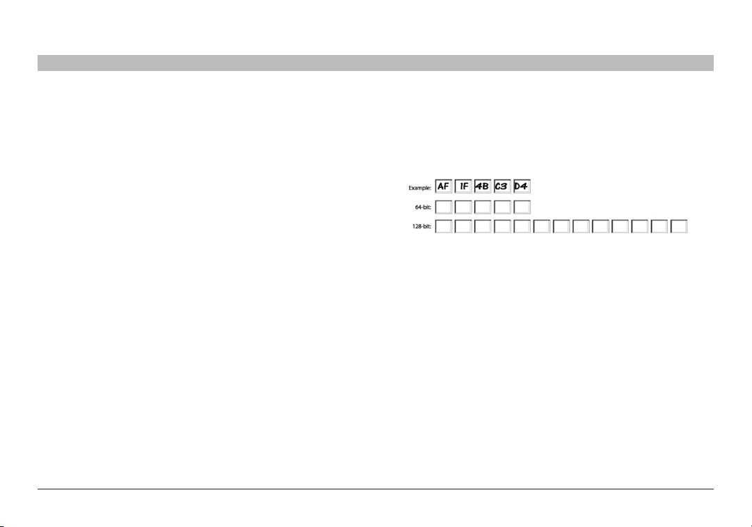
Using a Hexadecimal Key
A hexade cimal key is a mixture of numbers and let ters from A–F and 0– 9. 64-bit keys are 10 digits long and can be divided into five two-digit
number s. 128-bit keys are 26 digits long and can be divided into 13 two-digit numbers.
For instance:
AF 0F 4B C3 D4 = 6 4-bit key
C3 03 0F AF 0F 4B B2 C3 D4 4B C3 D4 E7 = 128-bit key
In the boxes below, make up your key by writing in two characters
between A– F and 0–9. You will use this key to program the encr yption
settings on your Router and your wireless computers.
Note to Mac users: Original Apple AirPort products support 64-bit
encryption only. Apple AirPort 2 products can support 64-bit or 128-bit
encryption. Please check your product to see which version you are
using. If you cannot configure your network with 128-bit encryption, try
64-bit encr yption.
6
10
N Wirel ess Modem Ro uter
51
USING THE WEB-BASED ADVANCED USER INTERFACE
SECTIONSTable of Contents 1 2 3 4 5 7 8 9
6
10
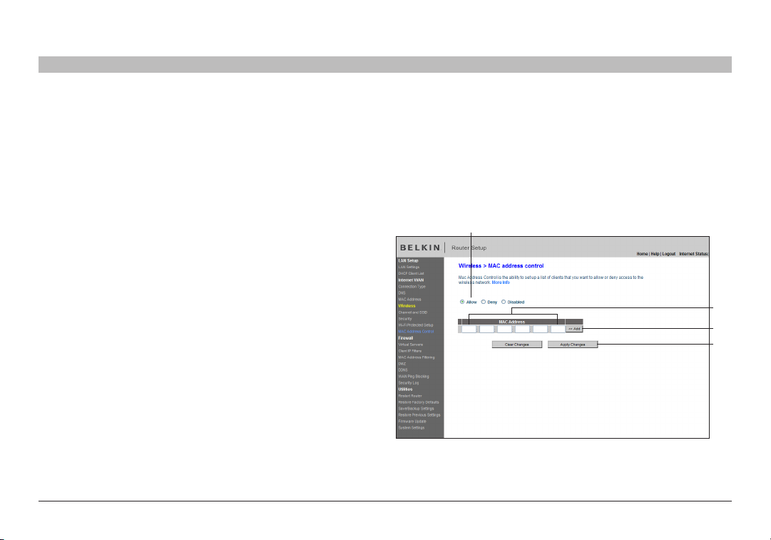
Setting MAC Address Control
The MAC address filter is a powerful security feature that allows you to specify which computers are allowed on the wireless network. Note: This list
applies only to wireless computers. This list can be configured so any computer attempting to access the wireless network that is not specified in the
filter list will be denied access. When you enable this feature, you must enter the MAC address of each client (computer) to which you want to allow
network access. The “Block” feature lets you turn on and off access to the network easily for any computer without having to add and remove the
computer’s MAC address from the list.
Setting up an Allow Access List
1. Select the “Allow” radio button (1) to begin setting up a list of
computers allowed to connect to the wireless network.
2. Nex t, in the “MAC Address” field that is blank (2), type in the MAC
address of the wireless computer you want to be able to access the
wireless network, then click “<<Add” (3).
3. Continue to do this until all of the computers you want to add have
been entered.
4. Click “Apply Changes” (4) to finish.
(1)
(2)
(3)
(4)
N Wirel ess Modem Ro uter
52
USING THE WEB-BASED ADVANCED USER INTERFACE
SECTIONSTable of Contents 1 2 3 4 5 7 8 9
6
10
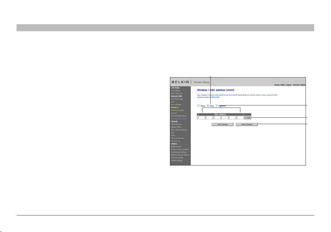
Setting up a Deny Access List
The “Deny Access” list lets you specify computers that you DO NOT want to access the network. Any computer in the list will not be allowed access
to the wireless network. All other s will.
1. Select the “Deny” radio button (1) to begin setting up a list of
(1)
computers to be denied access to the wireless network.
2. Nex t, in the “MAC Address” field that is blank (2), type in the MAC
address of the wireless computer you want to deny access to the
wireless network, then click “<<Add” (3).
3. Continue to do this until all of the computers you want to deny access
to have been entered.
4. Click “Apply Changes” (4) to finish.
(2)
(3)
(4)
N Wirel ess Modem Ro uter
53
USING THE WEB-BASED ADVANCED USER INTERFACE
SECTIONSTable of Contents 1 2 3 4 5 7 8 9
6
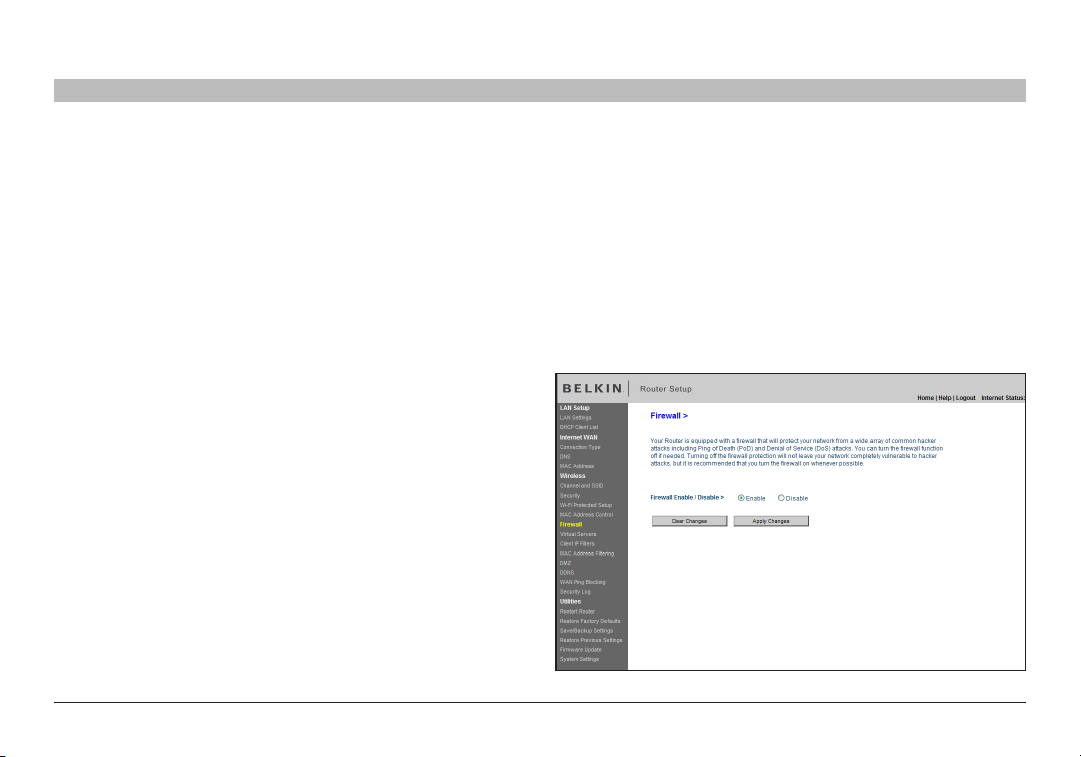
Configuring the Firewall
Your Router is equipped with a firewall that will protect your network from a wide array of common hacker attacks including:
• IP Spoofing
• Land Attack Ping of Death (PoD)
• Denial of Ser vice (DoS)
• IP with zero length
• Smurf Attack
• TCP Null Scan
• SYN flood
• UDP flooding
• Tear Drop Attack
• ICMP defect
• RIP defect
• Fragment flooding
The firewall also masks common por ts that are frequently used to
attack networks. These ports appear to be “stealth” meaning that for
all intents and purposes, they do not exist to a would-be hacker. You
can turn the firewall function off if nee ded; however, it is recommended
that you leave the firewall enabled. Disabling the firewall protection will
not leave your network completely vulnerable to hacker attacks, but it is
recommended that you leave the firewall enabled.
10
N Wirel ess Modem Ro uter
54
USING THE WEB-BASED ADVANCED USER INTERFACE
SECTIONSTable of Contents 1 2 3 4 5 7 8 9
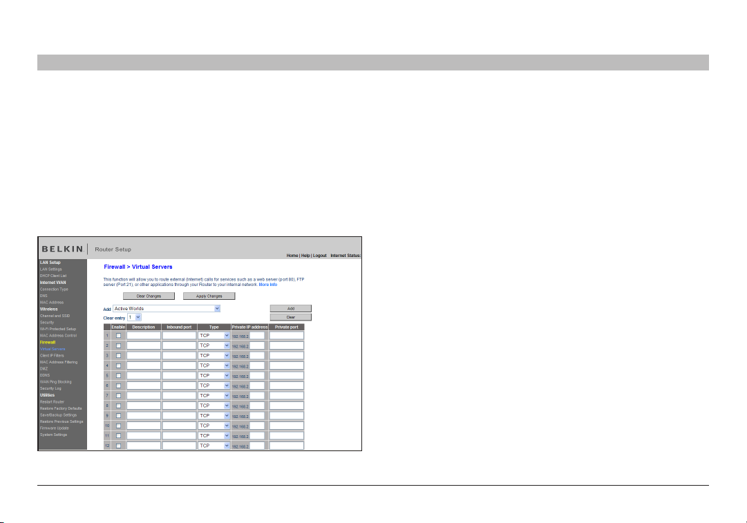
Configuring Internal Forwarding Settings
The Virtual Servers function will allow you to route ex ternal (Internet)
calls for ser vices such as a web server (port 80), FTP server (Port 21), or
other applications through your Router to your internal network. Since
your internal computers are protected by a firewall, computers outside
your network (over the Internet) cannot get to them be cause they cannot
be “seen”. A list of common applications has been provided in case you
need to configure the Virtual Server function for a specific application.
If your application is not listed, you will need to contact the application
vendor to find out which por t set tings you need.
6
Choosing an Application
Select your application from the drop-down list. Click “Add”. The
settings will be transferred to the next available space in the screen.
Click “Apply Changes” to save the setting for that application. To remove
an application, select the number of the row that you want to remove
then click “Clear”.
Manually Entering Settings into the Virtual Server
To manually enter settings, enter the IP address in the space provided
for the internal (ser ver) machine, the por t(s) required to pass (use a
comma between multiple por ts), select the por t type (TCP or UDP),
and click “Apply Changes”. You can only pass one por t per internal IP
address. Opening ports in your firewall can pose a security risk. You can
enable and disable settings very quickly. It is recommended that you
disable the settings when you are not using a specific application.
10
N Wirel ess Modem Ro uter
55
USING THE WEB-BASED ADVANCED USER INTERFACE
SECTIONSTable of Contents 1 2 3 4 5 7 8 9
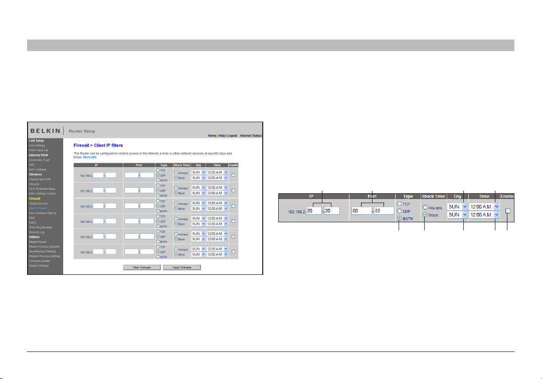
Setting Client IP Filters
The Router can be configured to restrict access to the Internet, email, or
other network services at specific days and times. Restriction can be set
for a single computer, a range of computers, or multiple computers.
6
10
To restrict Internet access to a single computer for example, enter the
IP address of the computer you wish to restrict access to in the IP fields
(1). Next, enter “80” in both the por t fields (2). Select “Both” (3). Select
“Block” (4). You can also select “Always” to block access all of the time.
Select the day to start on top (5), the time to start on top (6), the day to
end on the bot tom (7), and the time to stop (8) on the bottom. Select
“Enable” (9). Click “Apply Changes”. The computer at the IP address
you specified will now be blocked from Internet access at the times you
specified. Note: Be sure you have selected the correct time zone under
“Utilities> System Settings> Time Zone”.
(1) (2) (5)
(3) (4) (7) (8) (9)
(6)
N Wirel ess Modem Ro uter
56
USING THE WEB-BASED ADVANCED USER INTERFACE
SECTIONSTable of Contents 1 2 3 4 5 7 8 9
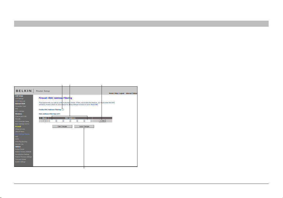
Setting MAC Address Filtering
The MAC address filter is a powerful security feature that allows you
to specify which computers are allowed on the network. Any computer
attempting to access the network that is not specified in the filter list
will be denied access. When you enable this feature, you must enter
the MAC address of each client (computer) on your network to allow
network access to each.
(1) (2) (3)
(4)
6
10
To enable this feature, select “MAC Address Filtering” and click “Enable
MAC Address Filtering” (1). Next, enter the MAC address of each
computer on your network by clicking in the space provided (2) and
entering the MAC address of the computer you want to add to the list.
Click “Add” (3), then “Apply Changes” (4) to save the settings. You can
have a MAC-address-filtering list of up to 32 compute rs.
Note: You will not be able to delete the MAC address of the computer
you are using to access the Router’s administrative functions (the
computer you are using now).
N Wirel ess Modem Ro uter
57
USING THE WEB-BASED ADVANCED USER INTERFACE
SECTIONSTable of Contents 1 2 3 4 5 7 8 9
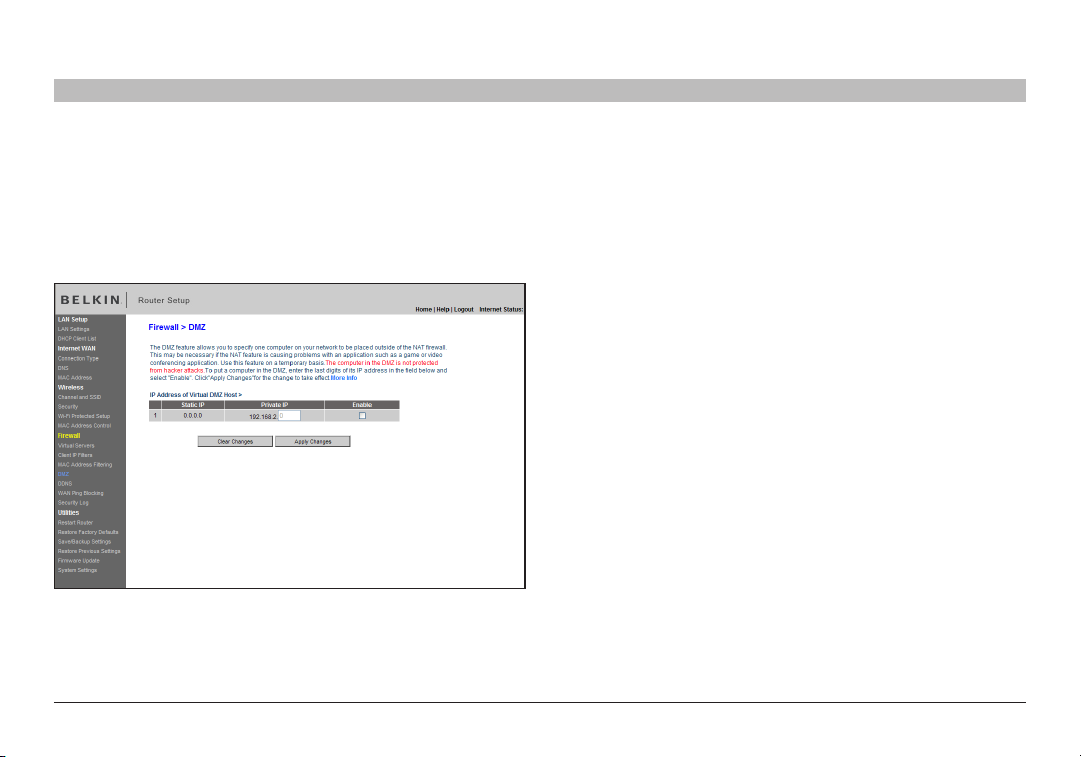
Enabling the Demilitarized Zone (DMZ)
The DMZ feature allows you to specify one computer on your network
to be placed outside of the firewall. This may be ne cessary if the firewall
is causing problems with an application such as a game or video
conferencing application. Use this feature on a temporary basis. The
computer in the DMZ is NOT protected from hacker attacks.
6
To put a computer in the DMZ, ente r the last digits of its IP address in
the IP field and select “Enable”. Click “Apply Changes” for the change
to take effect. If you are using multiple static WAN IP addresses, it is
possible to select which WAN IP address the DMZ host will be dire cted
to. Type in the WAN IP address you wish the DMZ host to direct to, enter
the last two digits of the IP addres s of the DMZ host computer, sele ct
“Enable” and click “Apply Changes”.
10
N Wirel ess Modem Ro uter
58
USING THE WEB-BASED ADVANCED USER INTERFACE
SECTIONSTable of Contents 1 2 3 4 5 7 8 9
6
10
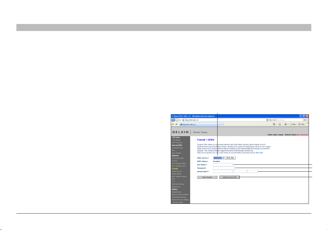
Using Dynamic DNS
The Dynamic DNS service allows you to alias a dynamic IP address to a static host name in any of the many domains DynDNS.org of fers, allowing
your network computers to be more easily accessed from various locations on the Internet. DynDNS.org provides this service, for up to five host
names, free to the Internet community.
The Dynamic DNSSM ser vice is ideal for a home website, file ser ver, or to make it easy to access your home PC and stored files while you’re at work.
Using the ser vice can ensure that your host name always points to your IP address, no matter how of ten your ISP changes it. When your IP address
change s, your friends and associates can always locate you by visiting yourname.dyndns.org instead!
To register free for your Dynamic DNS host name, please visit http://www.dyndns.org.
Setting up the Router’s Dynamic DNS Update Client
You must register with DynDNS.org’s free update service before using
this feature. Once you have your registration, follow the directions below.
1. Select DynDNS.org from the “DDNS Service” drop-down box (1).
2. Enter your DynDNS.org user name in the “User Name” field (2).
3. Enter your DynDNS.org password in the “Password” field (3).
4. Enter the DynDNS.org domain name you set up with DynDNS.org in the
“Domain Name” field (4).
5. Click “Update Dynamic DNS” to update your IP address (5).
Whenever your IP address assigned by your ISP changes, the Router will
automatically update D ynDNS.org’s servers with your new IP address.
You can also do this manually by clicking the “Update Dynamic DNS”
button (5).
(1)
(2)
(3)
(4)
(5)
N Wirel ess Modem Ro uter
59
USING THE WEB-BASED ADVANCED USER INTERFACE
SECTIONSTable of Contents 1 2 3 4 5 7 8 9
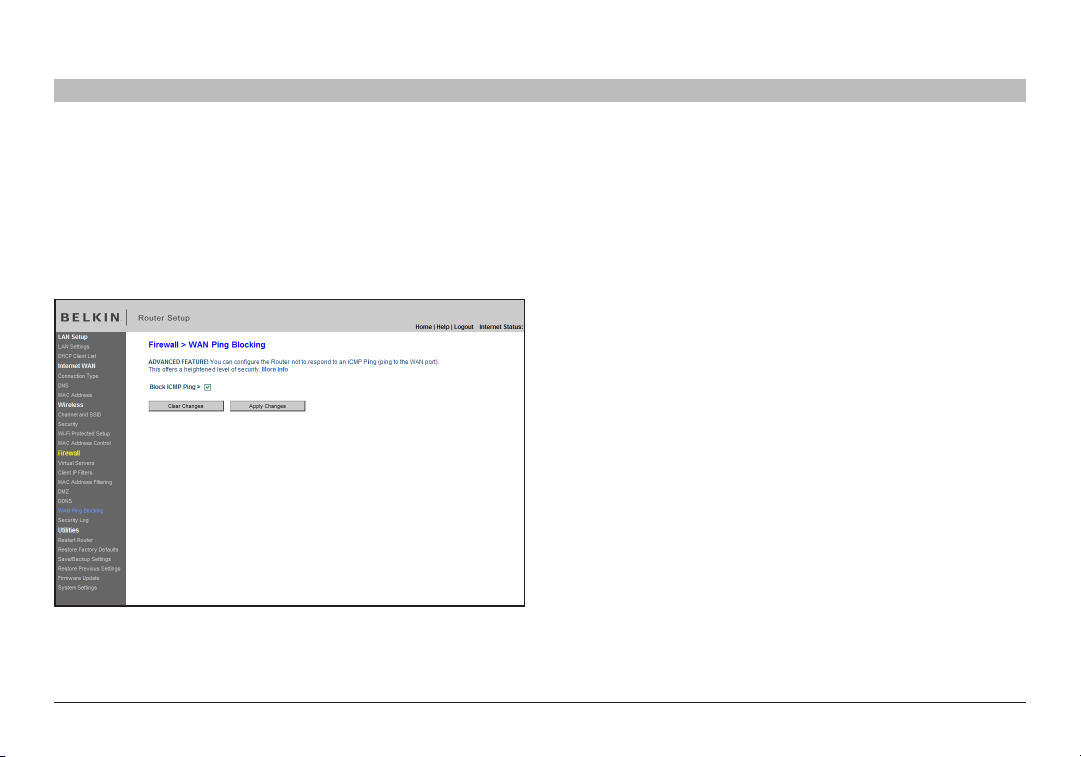
Blocking an ICMP Ping
Compute r hackers use what is known as “pinging” to find potential
victims on the Internet. By pinging a specific IP address and receiving a
response from the IP address, a hacker can determine that something
of interest might be there. The Router can be set up so it will not
respond to an ICMP ping from the outside. This heightens your Router’s
security level.
6
To turn off the ping response, select “Block ICMP Ping” (1) and click
“Apply Changes”. The Router will not respond to an ICMP ping.
10
N Wirel ess Modem Ro uter
60
USING THE WEB-BASED ADVANCED USER INTERFACE
SECTIONSTable of Contents 1 2 3 4 5 7 8 9
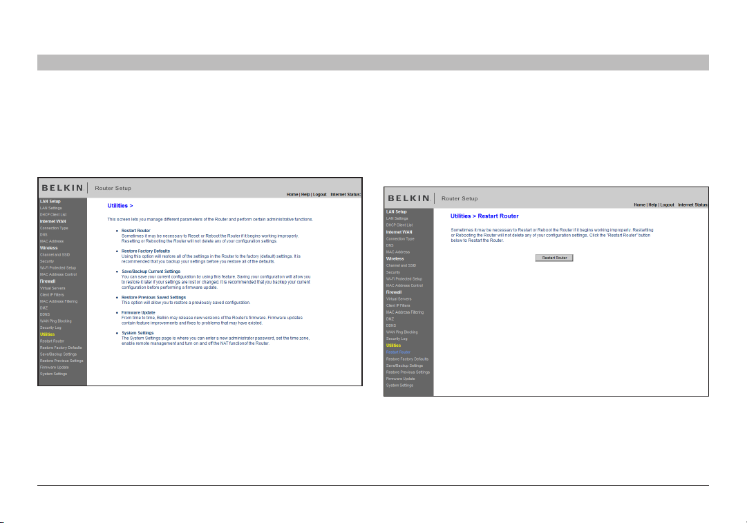
Utilities
The “Utilities” screen lets you manage dif ferent parameters of the Router
and perform certain administrative functions.
6
10
Restarting the Router
Sometimes it may be necess ary to restart or reboot the Router if it
begins working improperly. Restarting or rebooting the Router will NOT
delete any of your configuration set tings.
N Wirel ess Modem Ro uter
61
USING THE WEB-BASED ADVANCED USER INTERFACE
SECTIONSTable of Contents 1 2 3 4 5 7 8 9
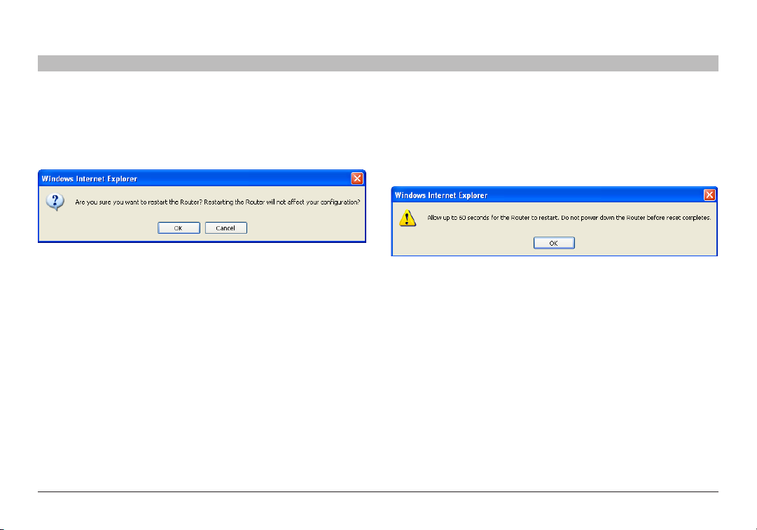
Restarting the Router to Restore Normal Operation
1. Click the “Restart Router” button.
2. The following message will appear. Click “OK”.
3. The following message will appear. Restar ting the Router can take up
to 60 seconds. It is impor tant not to tur n off the power to the Router
during the restart.
6
4. A 60-second countdown will appear on the screen. When the
countdown reaches zero, the Router will be restarted. The Router home
page should appear automatically. If not, type in the Router’s address
(default = 192.168.2.1) into the navigation bar of your browser.
10
N Wirel ess Modem Ro uter
62
USING THE WEB-BASED ADVANCED USER INTERFACE
SECTIONSTable of Contents 1 2 3 4 5 7 8 9
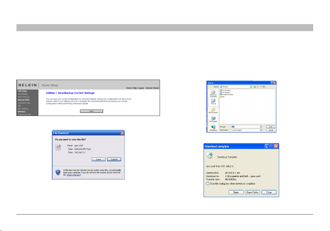
Saving a Current Configuration
You can save your current configuration by using this feature. Saving
your configuration will allow you to re store it later if your settings are
lost or changed. It is recommended that you back up your current
configuration before performing a firmware update.
1. Click “Save”. A window called “File Download” will open. Click “Save”.
6
2. A window will open that allows you to select the location where you
want to save the configuration file. Select a location. You can name
the file anything you want, or use the default name “user.conf”. Be
sure to name the file so you can locate it yourself later. When you have
selected the location and name of the file, click “Save”.
3. When the save is complete, you will see the window below. Click “Close”.
4. The configuration is now saved.
10
N Wirel ess Modem Ro uter
63
 Loading...