

Belkin F5D8630-4 Users Manual

1
Introduction
1
2
1
3
4
5
6
7
8
9
10
11
12
section
Thank you for purchasing the Belkin ADSL Modem with High-Speed
Mode Wireless G Router (the Router). In minutes you will be able to
share your Internet connection and network your computers with your
new Router. The following is a list of features that make your Router an
ideal solution for your home or small office network. Please be sure to
read through this User Manual completely, and pay special attention to
Appendix B entitled “Important Factors for Placement and Setup”.
Benefits of a Home Network
By following our simple setup instructions, you will be able to use
your Belkin home network to:
• Share one high-speed Internet connection with all the computers
in your home
• Share resources, such as files, and hard drives among all the
connected computers in your home
• Share a single printer with the entire family
• Share documents, music, video, and digital pictures
• Store, retrieve, and copy files from one computer to another
• Simultaneously play games online, check Internet email,
and chat
Advantages of a Belkin Wireless Network
Mobility – you’ll no longer need a dedicated “computer room”— now you
can work on a networked laptop or desktop computer anywhere within
your wireless range
Easy installation –
Belkin’s Easy Installation Wizard makes setup simple
Flexibility – set up and access printers, computers, and other
networking devices from anywhere in your home
Easy Expansion – the wide range of Belkin networking products let
you expand your network to include devices such as printers and
gaming consoles
No cabling required – you can spare the expense and hassle of
retrofitting Ethernet cabling throughout the home or office
Widespread industry acceptance – choose from a wide range of
interoperable networking products

32
Package Contents
• MIMO ADSL Modem Router
• RJ11 Telephone Cord - Gray
• RJ45 Ethernet Networking Cable - Yellow
• ADSL Microfilter*
• Power Adapter
• User Manual CD
*ADSL microfilter varies by country. If it’s not included, you will need to purchase
one.
System Requirements
• An active ADSL service with a telephone wall jack for connecting
the Router
• At least one computer with a Network Interface Card (NIC) and Internet
browser installed and correctly configured
• TCP/IP networking protocol installed on each computer connected to
the Router
• No other DHCP server on your local network assigning IP addresses to
computers and devices
Internet Connection Settings
Please collect the following information from your Internet Service Provider (ISP)
before setting up the ADSL Modem Wireless G Router.
• Internet connection protocol: _________ (PPPoE, PPPoA, Dynamic IP, Static IP)
• Multiplexing method or Encapsulation: __________ (LLC or VC MUX)
• Virtual circuit: VPI (Virtual Path Identifier) __________
(a number between 0 and 255)
• VCI (Virtual Channel Identifier) __________
(a number between 1 and 65535)
• For PPPoE and PPPoA users: ADSL account user name _____________ and
password _______________
• For static IP users: IP Address ___ . ___ . ___ . ___
Subnet Mask ___ . ___ . ___ . ___
Default Gateway Server ___ . ___ . ___ .
• IP address for Domain Name Server ___ . ___ . ___ . ___ (If given by your ISP)
Note: See Appendix C in this User Manual for some common DSL Internet
setting parameters. If you are not sure, please contact your ISP.
Make Sure You Have the Following

3
Knowing your Router
3
The Router is designed to be placed on a desktop. All of the cables exit from
the rear of the Router for better organization and utility. The LED indicators
are easily visible on the front of the Router to provide you with information
about network activity and status.
Front Panel
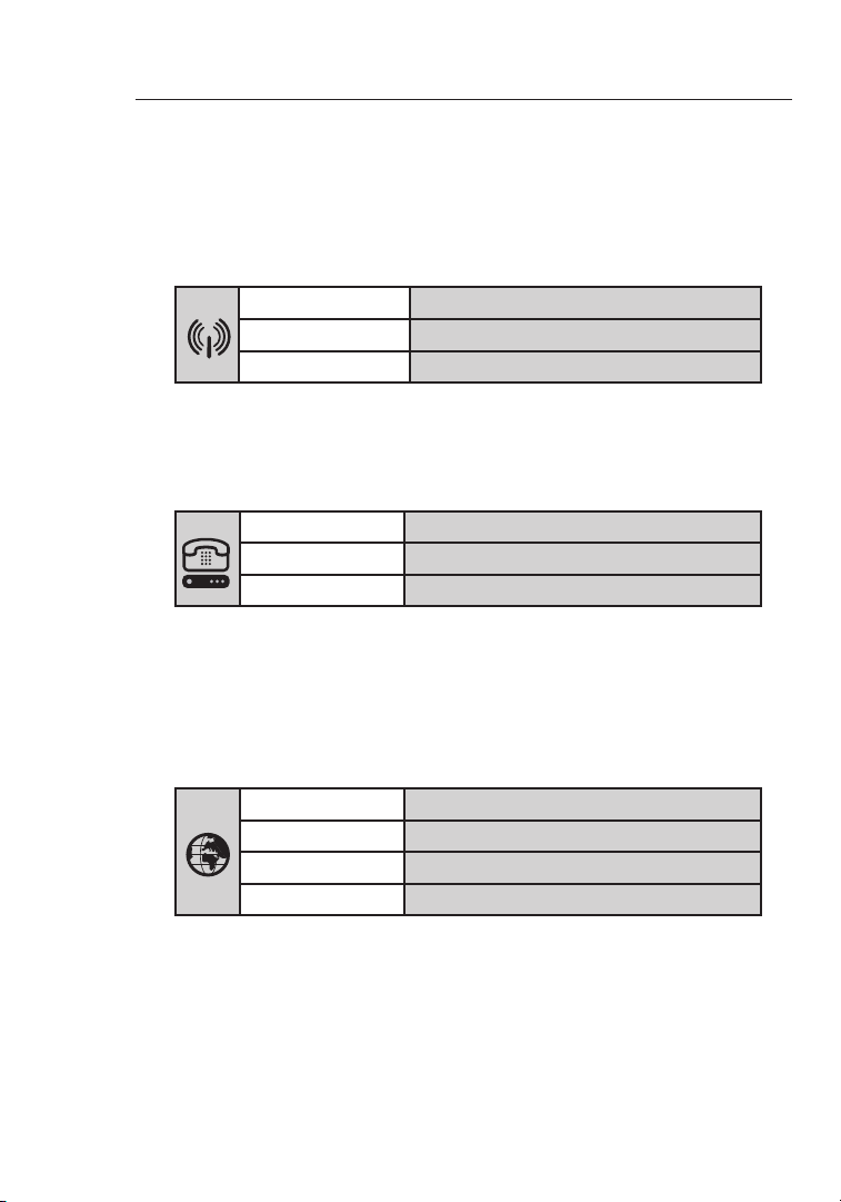
1. Power LED
When you apply power to the Router or restart it, a short period of time
elapses while the Router boots up. When the Router has completely
booted up, the Power LED becomes a SOLID light, indicating the Router
is ready for use.
OFF Router is OFF
Green Router is ON
Red Router failed to start
2. LAN Status LED
These LAN Status LEDs are labeled 1–4 and correspond to the
numbered ports on the rear of the Router. When a computer is properly
connected to one of the LAN ports on the rear of the Router, the LED
will light. Solid GREEN means a computer or a network-enabled device
is connected. When information is being sent over the port, the LED
blinks rapidly. ORANGE indicates a 10Base-T connection.
OFF No device is connected or computer is
powered off
Orange Ethernet link is up and 10Base-T
device connected
Orange - blinking When 10Base-T device transmitting
or receiving data
Green Ethernet link is up and
100Base-T connected
Green - blinking When 100Base-T device
transmitting or receiving data
(1) (4) (5)(3)
(2)
section
2
1
3
4
5
6
7
8
9
10
11
12
Knowing your Router
54
3. WLAN Status LED
The WLAN Status LED is solid GREEN when you enable the
wireless LAN function. It flashes when the Router is transmitting
or receiving data wirelessly.
OFF WLAN is off
Green WLAN is up and connected
Green - blinking When transmitted or receiving data
4. ADSL LED
The ADSL LED flashes GREEN during negotiation with your ISP.
It stays GREEN when the Router is connected properly to your
ADSL service.
OFF no ADSL connection
Green ADSL link is up and connected
Green -
blinking negotiating connection
5. Internet LED
The Internet LED shows you when the Router is connected to
the Internet. When the LED is OFF, the Router is NOT connected
to the Internet. When the LED is solid GREEN, the Router is
connected to the Internet. When the LED is blinking, the Router
is transmitting or receiving data from the Internet.
OFF No Internet connection
Green Connected to the Internet
Green -
blinking When transmitting or receiving data
Red Failed to get IP
5
Knowing your Router
5
section
2
1
3
4
5
6
7
8
9
10
11
12
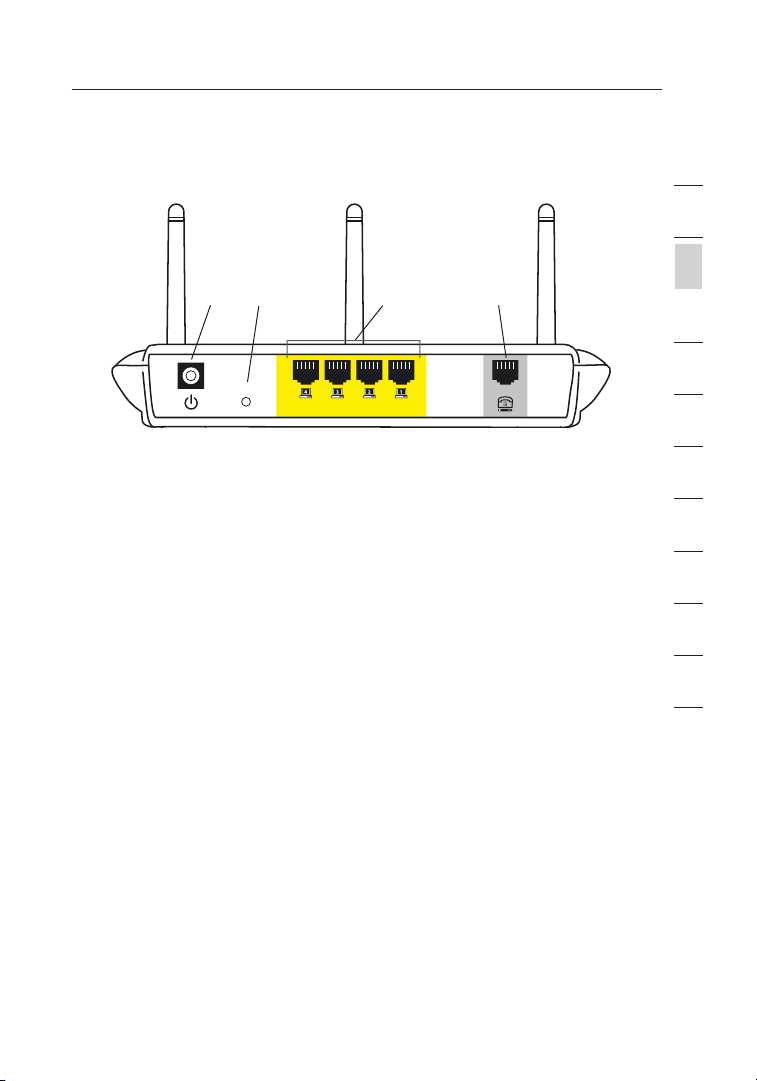
Back Panel
6. DSL Line
This port is for connection to your ADSL line. Connect your ADSL
line to this port.
7. Ethernet Ports
The Ethernet ports are RJ45, 10/100 auto-negotiation. The ports
are labeled 1 through 4. These ports correspond to the numbered
LEDs on the front of the Router. Connect your network-enabled
computers or any networking devices to one of these ports.
8. Reset Button
The “Reset” button is used in rare cases when the Router may
function improperly. Resetting the Router will restore the Router’s
normal operation while maintaining the programmed settings. You
can also restore the factory default settings by using the Reset
button. Use the restore option in instances where you may have
forgotten your custom password.
a. Resetting the Router
Push and hold the Reset button for one second then release
it. When the Power/Ready light becomes solid again, the
reset is complete.
b. Restoring the Factory Defaults
Press and hold the Reset button for 10 seconds then release
it. When the Power/Ready light becomes solid again, the
restore is complete.
9. Power Plug
Connect the included 15V DC power supply to this inlet.
Using the wrong type of power adapter may cause damage
to your Router.
(7)(9) (6)
(8)

Connecting your Router
76
Positioning your Router
Your wireless connection will be stronger the closer your computer
is to your Router. Typical indoor operating range for your wireless
devices is between 100 and 200 feet. In the same way, your wireless
connection and performance will degrade somewhat as the distance
between your Router connected devices increases. This may or may
not be noticeable to you. As you move farther from your Router,
connection speed may decrease. Factors that can weaken signals
simply by getting in the way of your network’s radio waves are metal
appliances, or obstructions, and walls. Please see “Appendix B:
Important Factors for Placement and Setup” in this User Manual for
more guidelines.
If you have concerns about your network’s performance that might be
related to range or obstruction factors, try moving the computer to
a position between five and 10 feet from the Router, in order to see
if distance is the problem. If difficulties persist even at close range,
please see the Troubleshooting section for solutions.
7
Connecting your Router
7
section
2
1
3
4
5
6
7
8
9
10
11
12
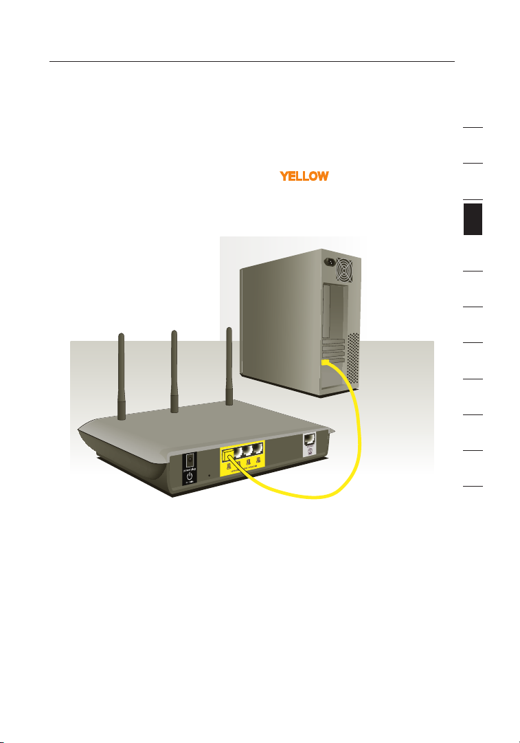
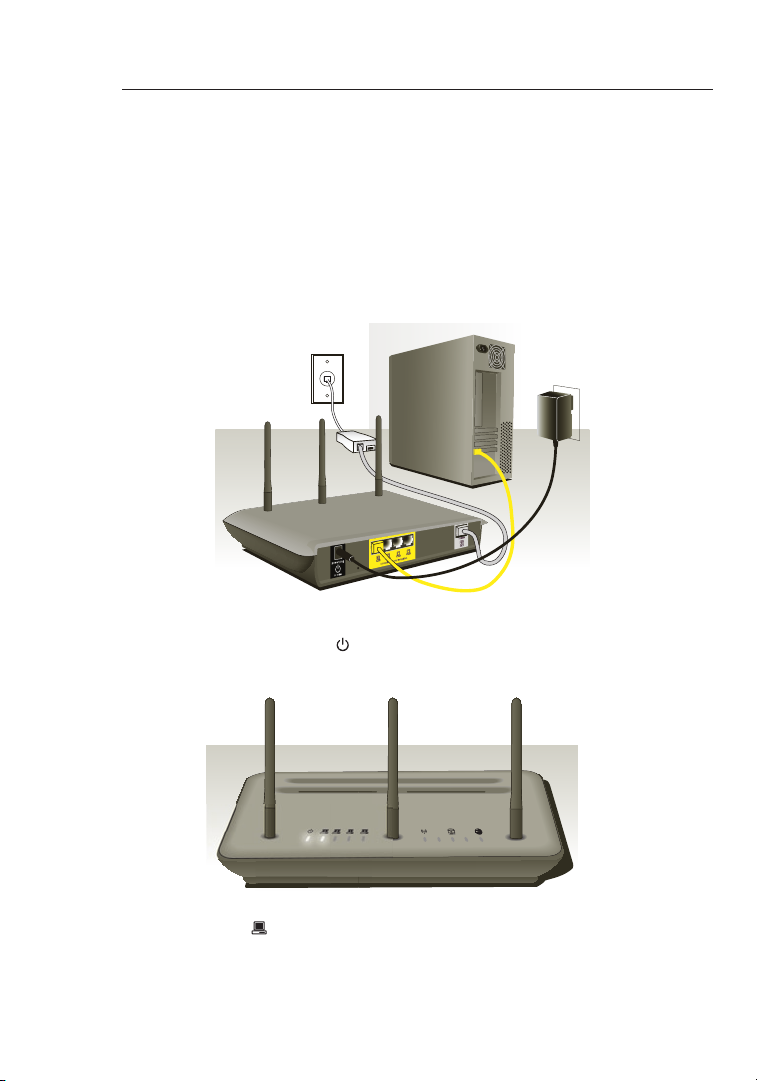
Connecting your Computers
1. Power off your computers and networking equipment.
2. Connect your computer to one of the YELLOW RJ45 ports on the
rear of the Router labeled “connections to your computers” by
using an Ethernet networking cable (one Ethernet network cable
is supplied).

Connecting your Router
98
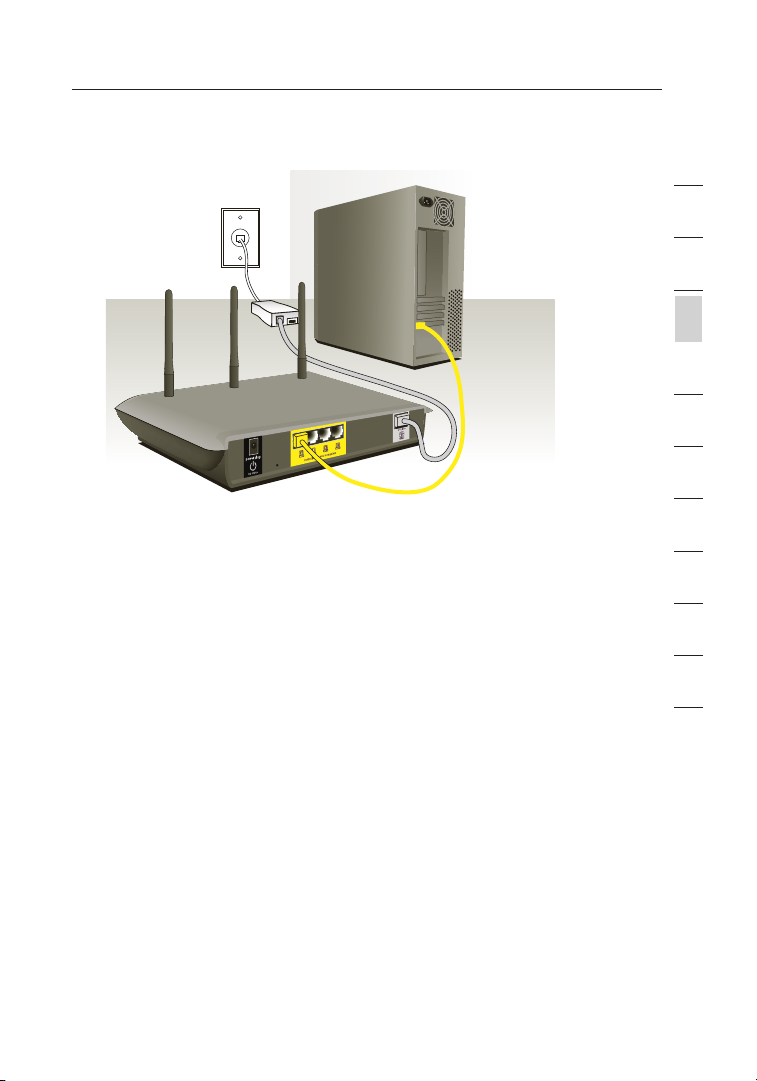
Connecting your ADSL Line
Connection for the Router to the ADSL line varies by country and
region. Typically it involves a microfilter or a microfilter with built-in
splitter to allow simultaneous use of ADSL service and telephone
service on the same telephone line. Please read the following steps
carefully and select appropriate method.
1. If your telephone service and ADSL service are on the same
telephone line, ADSL microfilters are needed for each telephone
and device, such as answering machine, fax machine, and caller
ID display. Additional splitters may be used to separate telephone
lines for telephone and the Router.
Note: Do not connect the ADSL microfilter between the wall jack
and the Router—this will prevent ADSL service from reaching
the modem.
2. If your telephone service and ADSL service are on the same
telephone line and you are using an ADSL microfilter with built-in
splitter, connect the splitter to the telephone wall jack providing
ADSL service. Then, connect the telephone cord from the ADSL
microfilter RJ11 port generally labeled “DSL” to the gray RJ11
port labeled “DSL line” on the back of your Router. Connect
telephony device to the other port on the ADSL splitter commonly
labeled “Phone”. An additional ADSL microfilter is needed for
another telephone and device on the same line.
9
9
section
2
1
3
4
5
6
7
8
9
10
11
12
Note: One RJ11 telephone cord is supplied. When inserting an
RJ11 plug, be sure the tab on the plug clicks into position to
ensure that it is properly seated.
3. If you have a dedicated ADSL service telephone line with an RJ11
wall jack, simply connect a telephone cord from the wall jack to
the gray RJ11 port labeled “DSL line” on the back of
your Router.
4. If you have an RJ45 wall jack for your ADSL service, connect an
RJ45-to-RJ11 converter to the wall jack. Then connect one end of
a telephone cord to the converter and the other end to the gray
RJ11 port labeled “DSL line” on the back of your Router.
Note: ADSL microfilter may or may not be provided depending on
your country.
Connecting your Router
1110
Powering Up your Router
1. Connect the supplied power adapter to the Router power-input
plug labeled “Power”.
Note: For safety and performance reasons, only use the supplied
power adapter to prevent damage to the Router.
2. After connecting the power adapter and the power source is turned on,
the Router’s power icon
on the front panel should be on. It might
take a few minutes for the Router to fully start up.
3. Turn on your computers. After your computers boot up, the LAN
status LED on the front of the Router will be on for each port
to which a wired computer is connected. These lights show
you the connection and activity status. Now you are ready to
configure the Router for ADSL connection.
Connecting your Router
11
Setting Up your Computers
11
section
2
1
3
4
5
6
7
8
9
10
11
12
In order for your computer to properly communicate with your Router, you
will need to change your computer’s “TCP/IP Ethernet” settings to “Obtain
an IP address automatically/Using DHCP”. This is normally the default
setting in most home computers.
You can set up the computer that is connected to the ADSL modem FIRST
using these steps. You can also use these steps to add computers to your
Router after the Router has been set up to connect to the Internet.
Manually Configuring Network Adapters in Windows XP, 2000, or NT
1.
Click “Start”, “Settings”, then “Control Panel”.
2. Double-click on the “Network and dial-up connections” icon
(Windows 2000) or the “Network” icon (Windows XP).
3. Right-click on the “Local Area Connection” associated with your
network adapter and select “Properties” from the drop-down menu.
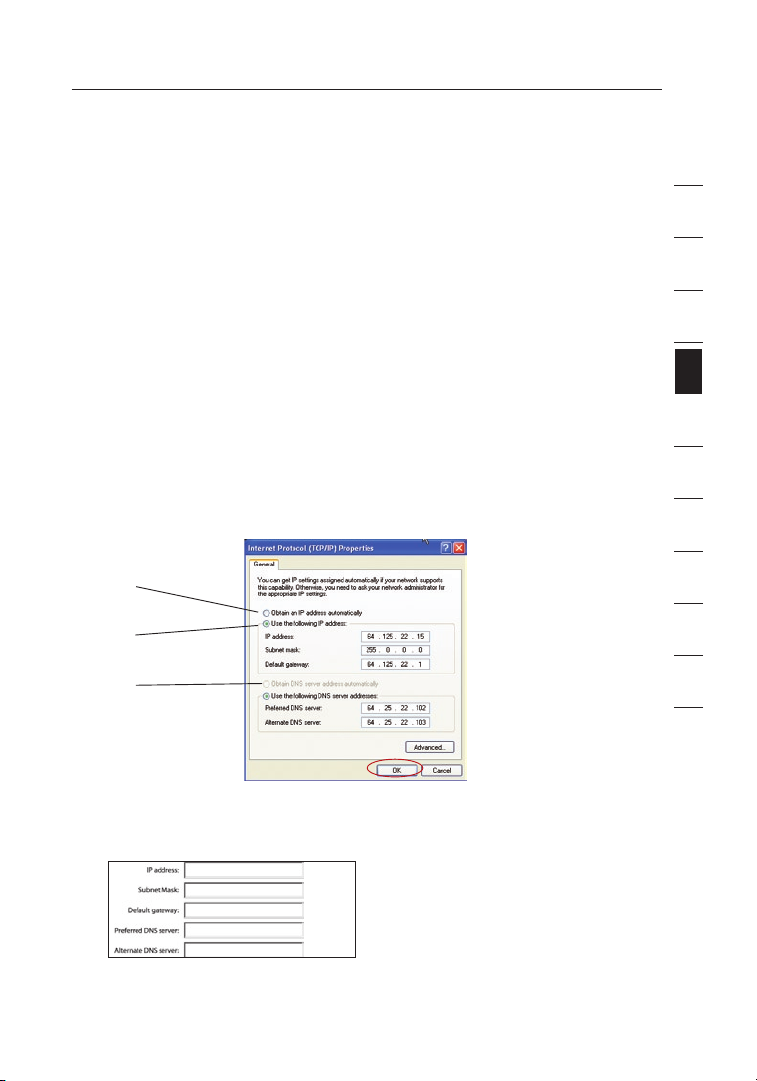
4. In the “Local Area Connection Properties” window, click “Internet
Protocol (TCP/IP)” and click the “Properties” button. The following
screen will appear:
5. If “Use the following IP address” (2) is selected, your Router will need to
be set up for a static IP connection type. Write the address information
the table below. You will need to enter this information into the Router.
6. If not already selected, select “Obtain an IP address automatically”
(1) and “Obtain DNS server address automatically” (3). Click “OK”.
Your network adapter(s) are now configured for use with the Router.
(1)
(2)
(3)
Setting Up your Computers
1312
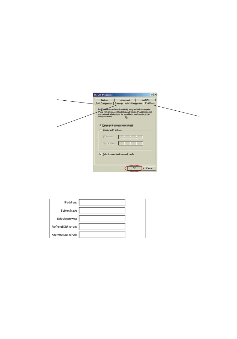
Manually Configuring Network Adapters in Windows 98SE or Me
1. Right-click on “My Network Neighborhood” and select “Properties” from
the drop-down menu.
2. Select “TCP/IP -> settings” for your installed network adapter. You will
see the following window.
3. If “Specify an IP address” is selected, your Router will need to be set up
for a static IP connection type. Write the address information in the table
below. You will need to enter this information into the Router.
(1)
(2)
(3)
4. Write the IP address and subnet mask from the “IP Address” tab (3).
5. Click the “Gateway” tab (2). Write the gateway address down in the chart.
6.
Click the “DNS Configuration” tab (1). Write the DNS address(es) in the chart.
7. If not already selected, select “Obtain an IP address automatically” on the
IP address tab. Click “OK”.
8. You will also need to delete the Gateway address from the Gateway tab
and DNS Configuration entries in order to properly be configured for
connection to the Belkin router.
Restart the computer. When the computer restarts, your network
adapter(s) are now configured for use with the Router.
13
Setting Up your Computers
13
section
2
1
3
4
5
6
7
8
9
10
11
12
Set up the computer that is connected to the cable or DSL modem
by FIRST using these steps. You can also use these steps to add
computers to your Router after the Router has been set up to connect
to the Internet.
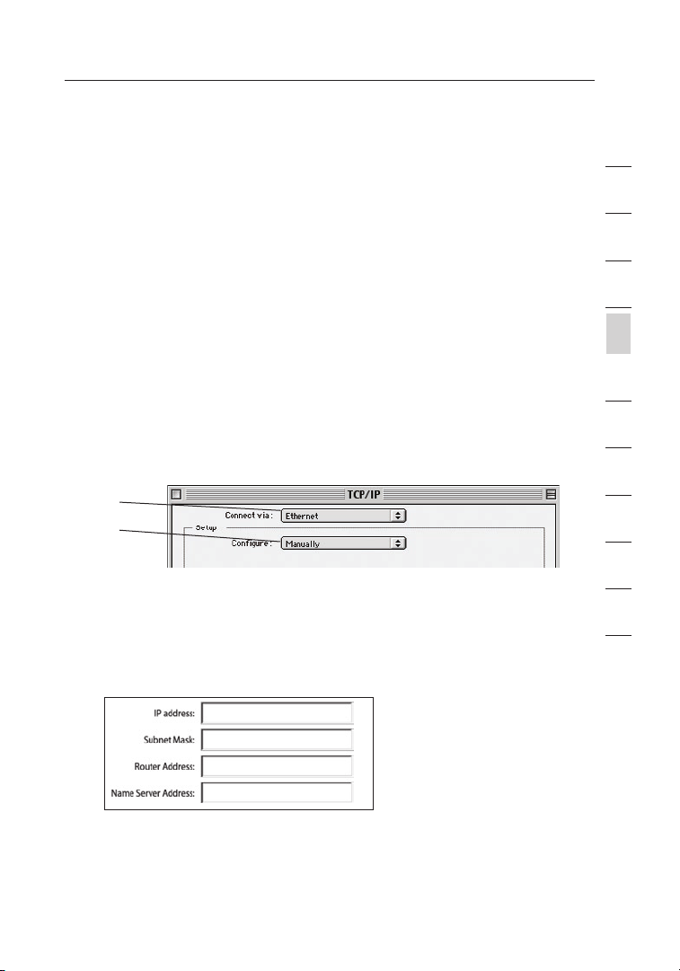
Manually Configuring Network Adapters in Mac OS
up to 9.x
In order for your computer to properly communicate with your Router,
you will need to change your Mac computer’s TCP/IP settings to DHCP.
1. Pull down the Apple menu. Select “Control Panels” and
select “TCP/IP”.
2. You will see the TCP/IP control panel. Select “Ethernet Built-In”
or “Ethernet” in the “Connect via:” drop-down menu (1).
3. Next to “Configure” (2), if “Manually” is selected, your Router
will need to be set up for a static IP connection type. Write the
address information in the table below. You will need to enter this
information into the Router.
(1)
(2)
Setting Up your Computers
1514
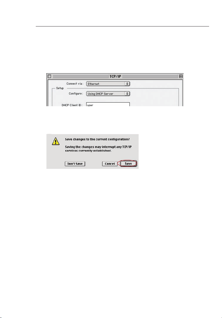
5. Close the window. If you made any changes, the following
window will appear. Click “Save”.
Restart the computer. When the computer restarts, your network
settings are now configured for use with the Router.
4. If not already set, at “Configure:”, choose “Using DHCP
Server”. This will tell the computer to obtain an IP address
from the Router.
 Loading...