

User Manual


Table of Contents
1. Introduction......................................1
Advantages of a Wireless Network ....................1
Placement of your N1 Vision.........................2
2. Product Overview .................................6
Product Features .................................6
3. Knowing your N1 Vision.............................9
Package Contents ................................9
System Requirements..............................9
Assistant Software System Requirements...............9
Hardware Characteristics ..........................10
4.
Connecting and Configuring your N1 Vision ............14
Step 1: Hardware Connections – Follow the Quick
Installation Guide ................................15
Step 2: Set Up the N1 Vision – Using the Plug-and-Play
Router Setup ...................................16
Interactive Display ...............................18
Information Screens ..............................18
Menu Screen ...................................22
Troubleshooting Assistant CD .......................22
5. Alternate Setup Method ...........................30
6.
Using the Web-Based Advanced User Interface .........46
Changing LAN Settings............................46
Viewing the DHCP Client List Page.................. 48
Configuring the Wireless Network Settings............ 48
Setting WPA Security .............................57
Setting WEP Encryption ...........................59
Using the Access Point Mode.......................61
Setting MAC Address Control ...................... 62
Configuring the Firewall ...........................64
Using Dynamic DNS ............................. 68
Utilities ....................................... 69
Restarting the N1 Vision .......................... 70
Updating the Firmware ........................... 75
7.
Manually Configuring Network Settings ...............83
8. Recommended Web Browser Settings.................88
9.
Troubleshooting .................................90
10. Information ...................................106


Introduction
Thank you for purchasing the Belkin N1 Vision wireless router (the N1
Vision). Following are two short sections—the first discusses the benefits
of home networking, and the other outlines best practices that maximize
your wireless home network range and performance. Please be sure to
read through this User Manual completely, and pay special attention to
the section entitled “Placement of your N1 Wireless N1 Vision” on the next
page. By following our simple setup instructions you will be able to use
your Belkin Home Network to:
• Shareonehigh-speedInternetconnectionwithallthecomputersin
your home
• Share
• Shareasingleprinterwiththeentirefamily
• Sharedocuments,music,video,anddigitalpictures
• Store,
• Simult an eously play games onli ne,c heck Inter netemail,and chat
Advantages of a Wireless Network
Here are some of the advantages of setting up a Belkin
Wireless Network:
•
• Easy installation – Belkin’s Easy Installation Wizard makes
•
• Easy expansion – the wide rang e of Bel ki n n et working products le t
•
• Widespread industry acceptance – cho os e f rom a wide rang e of
resources,suchasfilesandharddrivesamongallthe
connected computers in your home
retrieve,andcopyfilesfromonecomputertoanother
Mobility – you’ll no longer need a dedicated “computer
roo m”—now you can work on a networ ke d l ap top or d esktop
computer anywhere within your wireless range
setup simple
Flexibility – se t u p and ac ce ss pr inters, comp ut ers, and other
networking devices from anywhere in your home
you expand you r net wo rk to in clude device s suc h a s pri nters and
gaming consoles
No cabling required – you can spare the expense and hassle of
retrofitting Ethernet cabling throughout the home or office
interoperable networking products
section
1
2
3
4
5
6
7
8
9
10
1

Introduction
32
Revolutionary N1 Wireless Technology with MIMO (N1 MIMO)
Your Belkin Vi sion wireless router uses a new smart-an tenna technology
called Multiple Input Multiple Output (MIMO). N1 MIMO complies
with the IEEE draft 802.11n specification. It increases speed, range,
reliability, and spectral efficiency for wireless networking systems.
The element that makes Belkin’s N1 MIMO technology different from a
conventional radio is the use of multiple antennas and two simultaneous
data streams to deliver wireless transfers around your home or office. A
conventional radio uses one antenna to transmit a data stream. Belkin’s
N1 MIMO technology, on the other hand, uses three antennas. This
design helps combat distortion and interference. Belkin’s N1 MIMO is
multidimensional. It builds on one-dimensional smart-antenna technology
by simultaneously transmitting two data streams through the same channel,
which increases wireless capacity.
Another element that enhances Belkin’s N1 MIMO technology is the use of
aggregation as specified in the draft 802
space between packets and combining multiple smaller packets into one
larger packet, Belkin’s N1 MIMO technology can transmit more data through
available bandwidth.
Think of conve nt ional radio trans mi ssion as a two-lane highw ay. The
speed limit go ve rns the maxim um al lowable flow of traffic through
that lane. Com pa red wit h c on ventional radi os, o ne-dimens io nal
smart-antenna s ystems help move tra ffic through tha t lan e f as ter
and more reli ab ly—analog ous t o a fo ur- lane ro ad on wh ic h t raff ic
consiste ntly moves at a rate closer to the speed limit . B el kin’s N1
MIMO techno lo gy helps traffic move at the speed limit and ope ns
more l anes—to become th e s up erhighway in this exam ple. The r ate of
traffic flow is multiplied by the number of lanes that are opened.
.11n standard. By shortening the
Placement of your N1 Vision
Important Factors for Placement and Setup
Your w irel ess c onnection wi ll be st rong er th e c lo ser your computer is
to your N1 Vis ion. Typi cal indoor operat in g r ange for wireless device s
is between 100 and 200 feet.
In the same way, your wireless connection and performance will degrade
somewhat as the distance between your N1 Vision and connected devices
increases. This may or may not be noticeable to you. As you move further
from your N1 Vision, connection speed may decrease. Factors that can
weaken signals simply by getting in the way of your network’s radio waves
are metal appliances or obstructions, and walls.
2

Introduction
If you have concerns about your netwo rk ’s perfo rm ance that might be
rel ated to range or obstru ct ion f actors, try movin g t he co mputer to a
position between five and 10 feet from the N1 Vision in order to see
if distance is the problem. If difficult ies p ersist even at close rang e,
please contact Belkin Technical Support.
Note: W hile some of the items liste d bel ow ca n a ffec t n et work
performance, they will not prohibit your wireless network from
function ing; if you a re co nc erned that yo ur ne twork is not operating at
its maximum effectiveness, this checklist may help.
section
1
2
3
4
1. N1 Vision
Place your N1 Vision, the central connection point of your
network, as cl os e a s p os sible to the center of your wireless
network devices.
To ac hieve the best wireless netwo rk co verage for your “wireless
clients” (i .e ., computers enab led b y B elkin Wireless Notebo ok
Network Cards, Wireless Desktop Network Cards, and Wireless
USB Adapters):
•
• In mult is tory homes, place th e N1 Vision on afloor that is as
• TrynottoplacetheN1Visionnearacordless2.4GHzphone.
2. Avoid Obstacles and Interference
If your wireless signa l s ee ms we ak in so me spots, make sure that
EnsurethatyourN1Vision’snetworkingantennasareparallel
to each other, and are position ed ve rtically (towa rd the
ceiling) . I f y ou r N 1 Visio n its el f i s p os itioned vert ic ally, po in t
the antennas as much as possible in an upward direction.
close to the center of the hom e as pos si ble. This may mean
placing the N1 Vision on an upper floor.
Avo id placing your N1 Vision near devi ce s t ha t m ay em it radio
“noise,” su ch as mi crow av e o vens. Dense objec ts th at ca n i nhibit
wireless communication include:
• Refrigerators
• Washers
• Metalcabinets
• Large
• Metallic-based,UV-tintedwindows
objects suc h a s the se are not bloc ki ng th e s ignal’s pa th (b etween
your computers and N1 Vision).
and/ordryers
aquariums
5
6
7
8
9
10
32

Introduction
54
3. Cordless Phones
If the perform an ce of yo ur wi re le ss network is impaired after
attending to the above issues, and you have a cordless phone:
• Try moving cordless pho ne sa wa yf rom you r N1 Vision andyour
wireless-enabled computers.
• Unplug and remove thebatt er yf rom any cordless ph on e
that operates on the 2.4GHz band (check manufacturer’s
information). If this fixes the problem, your phone may
be interfering.
• Ifyourphonesupportschannelselection,changethechannel
on the phone to the farthes t c ha nnel from yo ur wi re le ss
network. Fo r e xa mple, change the phone to chan nel 1 an d
move your N1 Vision to channel 11. See your pho ne ’s user
manual for detailed instructions.
• Ifnecessary,considerswitchingtoa900MHzor5GHz
cordless phone.
4. Choose the “Quietest” Channel for your Wireless Network
In locat io ns where h om es or offi ce s a re clos e tog ether, such as
apartment buildings or office complexes, there may be wireless
networks nearby that can conflict with yours.
Use the Site Surv ey ca pabilitie s fou nd in th e W irel es s U tility of
your wireless adapter to locate any other wireless networks that
are av ailable (see your wi reless ad ap ter’s us er ma nual), and move
your N1 Vis ion and compute rs to a chann el as fa r a wa y f rom
other networks as possible.
• Exp eriment with more than on e of the available c hannels, in
order to find t he clearest con nection and avoid inter feren ce from
neighboring cordless phones or other wireless devices.
• For Belkin wireless networking products, use the detailed Site
Survey and wireless channel information included with your
wireless network c ard. See your network card’s user g uide for
more information.
The se gu idelines shoul d a ll ow you t o c over the maximum
possible area with your N1 Vision. Should you need to cover an
even wider area, we suggest the Belkin Wireless Range
Extender/AccessPoint.
4

Introduction
5. Secure Connections, VPNs, and AOL
Secure connections typically require a user name and
password, and are used where s ecurity is import an t. Secure
connections include:
• Vir tual Private Ne tw ork( VPN) connect io ns,often used to
connect remotely to an office network
“BringYourOwnAccess”programfromAmericaOnline
• The
(AOL), which lets you use AOL through broadband provided by
another cable or DSL service
• Mostonlinebankingwebsites
• Manycommercial we bs ites that re quirea us er na me an d
password to access your account
Secure connect io ns can b e i nterrupte d by a comput er’s power
management setting, which causes it to “go to sleep.” The
simplest so lu tion to avoid this is to simply reconnec t by rerunni ng
the VPN or AOL software, or by re-logging into the secure
website.
A second alte rnative is to change yo ur co mputer’s p ower
manageme nt se ttings so it does not go to sleep; howeve r, th is
may not be appropriate for port ab le computers . To change your
power management setting under Windows, see the “Power
Options” item in the Control Panel.
If you contin ue to ha ve di ffic ul ty with Secure Connectio ns , V PNs,
and AOL, pleas e review the step s a bo ve to be su re you have
addressed these issues.
section
1
2
3
4
5
6
7
8
9
10
For more information regarding our networking products, visit our website
at www.belkin.com/networking or call Belkin Technical Support at:
US: 877-736-5771
800-223-5546 ext. 2263
310-898-1100 ext. 2263
UK: 0845 607 77 87
Australia: 1800 235 546
New Zealand: 0800 235 546
Singapore: 65 64857620
Europe: www.belkin.com/support
54

Product Overview
76
Product Features
In minutes you will be able to share your Internet connection and
network you r c om puters. The follo wi ng is a lis t o f fea ture s t ha t m ake
your new Belki n N1 Vision an ideal solu ti on for y our home or small
office network.
Works with Both PCs and Mac® Computers
The N1 Vision supports a variety of networking environments
including Mac OS® X v10.4 or v10.5; Windows® 2000, XP, or Vista®;
and others. Al l tha t i s nee de d i s a n I nt ernet browser and a netwo rk
adapterthatsupportsTCP/IP(thestandardlanguageoftheInternet).
Interactive Display
The interac ti ve display on the front of t he N1 Visi on in dicates which
features are in op eration. You’ll know at-a- gl ance whether yo ur N1
Vis ion is c onnected to the Inte rnet. This feat ure eli mi nates the need
for advance d s of tware a nd st atus-moni to ring procedures typically
needed through the use of a computer.
Web-Based Advanced User Interface
You ca n s et up th e N1 Vision’s advanced func tions easily through
your web browser, without having to install additional software onto
the compute r. Th ere are no disks to install or keep trac k o f a nd , b es t
of all, you can make change s a nd pe rf orm setup functio ns from any
computer on the network quickly and easily.
NAT IP Address Sharing
Your N 1 Visio n emp loys Network Address Trans la tion (NAT) to share
the single IP address assigned to you by your Internet Service
Pro vider (ISP) while sa vi ng the c ost of a dding additi on al IP ad dres ses
to your Internet service account.
SPI Firewall
Your N1 Vision is equipped with a firewall that will protect your network
from a wide array of common hacker attacks including IP Spoofing,
Lan d Attack, Ping of De ath (PoD), Denial of Service (DoS ), IP with zero
len gth, Smurf Attack, TCP Null Scan, SYN flood , UDP floo ding, Tear
Drop Attack, ICMP defect, RIP defect, and fragment flooding.
6

Product Overview
1
9
2
3
4
5
6
7
8
10
76
Integrated 10/100/1000 4-Port Switch
The N1 Vision has a built-in, four-port network switch to allow your
wired computers to share printer s, da ta and M P3 files, digital ph ot os,
and much more. The switch featu res aut om atic detection so it will
adjust to the speed of conn ec ted devices. The swi tc h w il l t ransfer
data between computers and the Internet simultaneously without
interrupting or consuming resources.
Universal Plug and Play (UPnP)
UPnP is a technolog y t ha t o ffer s s ea mless operatio n o f voi ce
messaging, video messaging, games, and other applications that
are UPnP-compliant.
Support for VPN Pass-Through
If you connect to your office network from home using a VPN
connecti on, y our N1 Vis io n w ill a llow your VPN-equ ipped computer to
pass through the N1 Vision and to your office network.
Built-In Dynamic Host Configuration Protocol (DHCP)
Built-In Dy na mic Host Configur ation Pro tocol (DHCP) on-b oa rd ma ke s
for the easies t pos si ble connecti on of a netwo rk. T he DH CP server
will assign IP addresse s t o eac h c om puter automati cally so there is
no need for a complicated networking setup.
Belkin Troubleshooting Assistant CD
The Troubleshoo ti ng Assistant soft ware ta ke s t he gu esswork out of
setting up you r N1 Vision. This soft ware au to matically de te rmines
your network settings for you and sets up the N1 Vision for
connecti on to yo ur IS P. I n a matt er of mi nu tes, your N1 Vi sion will be
up and you will be surfing the Internet.
Note: Troubl es hooting Assi st ant software is compatib le wi th Wi ndows
2000, XP, and Vis ta; and Mac OS X v1 0.4 a nd v10.5. If you are us ing
another ope ra ting system, the N1 Vision can be set up using the
Alternate Setup Method described in this User Manual (see page 30).
section

Product Overview
Integrated N1 Wireless Access Point
N1 MIMO is an e xciting new wireles s tec hn ology based on the draft
IEEE 802.11n specification. It employs MIMO (Multiple Input Multiple
Output) sma rt -antenna tec hn ology that achiev es da ta rates of up t o
300Mbps. * A ct ual throughput is typica ll y l ower than the connecte d
data rate and will vary depending on your networking environment.
*NOTE: The standard transmi ss ion rate—300 Mb ps—is the physica l
data rate. Actual data throughput will be lower.
MAC Address Filtering
For added secu ri ty, you can set up a list of MAC addresses (uniqu e
client iden ti fiers) that are allowed acces s t o you r n et work. Every
computer ha s i ts ow n M AC ad dres s. Si mply enter these MAC
addresses into a list usin g the Web-B as ed Advanced User Int er face
and you can control access to your network.

Knowing your N1 Vision
1
9
3
4
5
6
7
8
10
Package Contents
• BelkinN1VisionWirelessRouter
• QuickInstallationGuide
• Belkin
A ssistant CD with Use r Man ua l
• RJ45EthernetNetworkingCable
• PowerSupply
System Requirements
• Bro adband Inter netconnec ti on such as ac ab le or DS Lm odem
withRJ45(Ethernet)functionality
• Atleastonecomputerwithaninstallednetworkinterfaceadapter
• TCP/IP
networkingprotocolinstalledoneachcomputer
• Internetbrowser
Assistant Software System Requirements
• A computer run ni ng Wi ndows2000, XP, or Vi sta;
or Mac OS X v10.4 or v10.5
• Minimum1GHzprocessorand512MBRAM
• Internet
browser
2
section
98
Knowing your N1 Vision
1110
Hardware Characteristics
The N1 Vi si on has b een designed to be plac ed on a deskt op . A ll of
the cables exi t from the BACK of the N1 Vi sion for better org anization
and utility. The N1 Visi on’s inter active display is easi ly vi sible on
the FRONT of the N1 Vi sion to prov ide y ou with informa ti on ab out
network activity and status.
(D)
(A)
(B)
(C)
10

Knowing your N1 Vision
1
9
2
3
4
5
6
7
8
10
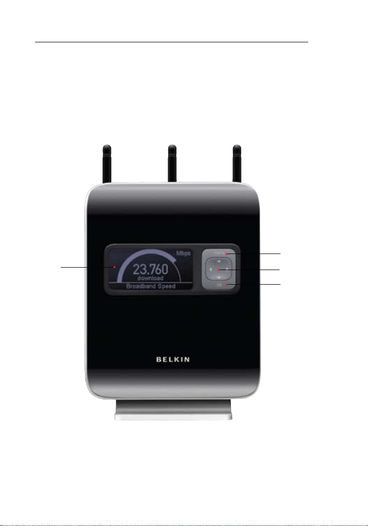
A. Interactive Display
The interactive display is on the front of the N1 Vision, which
indicates which features are in operation.
B. 4-Way Keypad
The keypad enables the movement of the up, down, left, and right
function that may apply to the screen shown in the interactive
display.
C. OK Button
For most screens in the interactive display, the “OK” button will
activate the desired feature.
D. Menu Button
Pushing this button will take you back to the Menu Screen within
the interactive display.
section
1110
Knowing your N1 Vision
1312
(G)
(E)
(H)
(F)
12

Knowing your N1 Vision
1
9
2
3
4
5
6
7
8
10
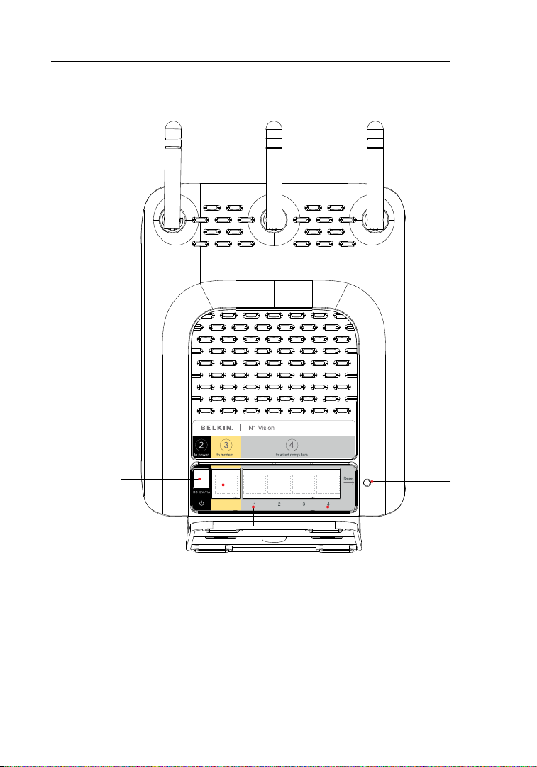
E. Connections to Wired Computers – Gray Ports
Connect your wired (non-wireless) computers to these ports.
TheseportsareRJ45,10/100/1000auto-negotiation,auto-
uplinkin g p or ts for s tandard UTP category 5 or 6 Ether net c able.
The ports are labeled 1 through 4. Use the gray cable provided to
connect your computer to any one of these ports.
F. Connection to Modem – Yellow Port
This port is for conne ct ion t o y our c able or DSL modem. Use the
cable that was provided with your modem to connect the modem
to this port. Use of a cable other tha n the on e sup pl ied with the
cable modem may not work properly.
G. Reset Button
The “Reset” button is used in rare cases when the N1 Vision
may functio n i mp rope rly. Reset ti ng the N 1 Vis io n w il l res to re the
N1 Vis ion’s norm al op eration whil e mai ntaining the programm ed
settings. You can also restore the factory default settings by
using the “Res et ” b ut ton. Use the re store o pt ion in i nstances
where you may have forgotten your custom password.
i. Resetting the N1 Vision
Pre ss and h old the “Reset” butt on fo r a t l ea st th re e s ec onds,
but no longer than five seconds. The LCD on the N1 Vision
will indicate that it is resetting. When the N1 Vision Network
Status screen appears, the reset is complete.
ii. Restoring the Factory Defaults
Pre ss and h old the “Reset” butt on fo r a t l ea st 10 se conds,
then release it. The LCD on the N1 Vi si on will indicate tha t
it is res to ring factory de fa ults. When the N1 Vi sion Network
Status screen appears, the restore is complete.
H. Power Jack – Black
Connecttheincluded12V/1.0ADCpowersupplytothisjack.
section
1312
Connecting and Configuring your N1 Vision
1514
Verify the contents of your box. You should have the following:
• BelkinN1VisionWirelessRouter
• QuickInstallationGuide
• Belkin
• RJ45EthernetNetworkingCable
• PowerSupply
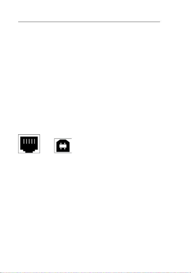
Modem Requirements
Yourc able or DSLm odem must be equippe d wit ha n RJ4 5E th ernet
port. Many mod em sh av eb otha nR J45E thern et po rt anda US B
connection. If you have a modem with both Ethernet and USB, and
are using the USB connection at this time, you will be instructed to
use theRJ45Ethernet port during the in st allation procedure. If your
modem has only a USB port, you can request a different type of
modem from your ISP, or you can, in some cases, pu rcha se a mod em
thathasanRJ45Ethernetportonit.
Ethernet USB
AssistantCDwithUserManual
14
Connecting and Configuring your N1 Vision
A
LAN
WAN
modem router back of computer WWW
routersetup
BCD
F
existing cable
new cable from package
E
2
3
4
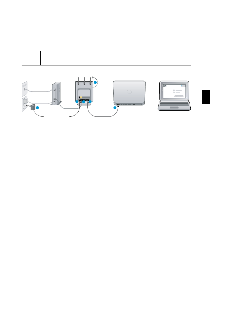
Step 1
Hardware Connections – Follow the Quick Installation
Guide (QIG)
A. Plug the power supply into the wall outlet.
B. Plug the other end into the black port on the N1 Vision.
C. Find the cable conne cting the modem and compu te r**. Unplug
it fro m t he co mputer and plug it into the yello w p or t o n t he
N1 Vision.
**If you are rep la cing an existing router, find the cab le co nnecting
the modem and old router. Disco nn ect it f ro m the ol d router and
plug it into the yellow port on your Belkin N1 Vision.
D. Co nn ect t he new c able (provided in the box) to any gray port on
the N1 Vision.
E. C onnect the other end of that cabl e t o a netw or king (Ethernet)
port on your computer.
1
2
3
section
4
5
6
7
8
9
10
F. Rotate the antennas up.
1514
Connecting and Configuring your N1 Vision
1716
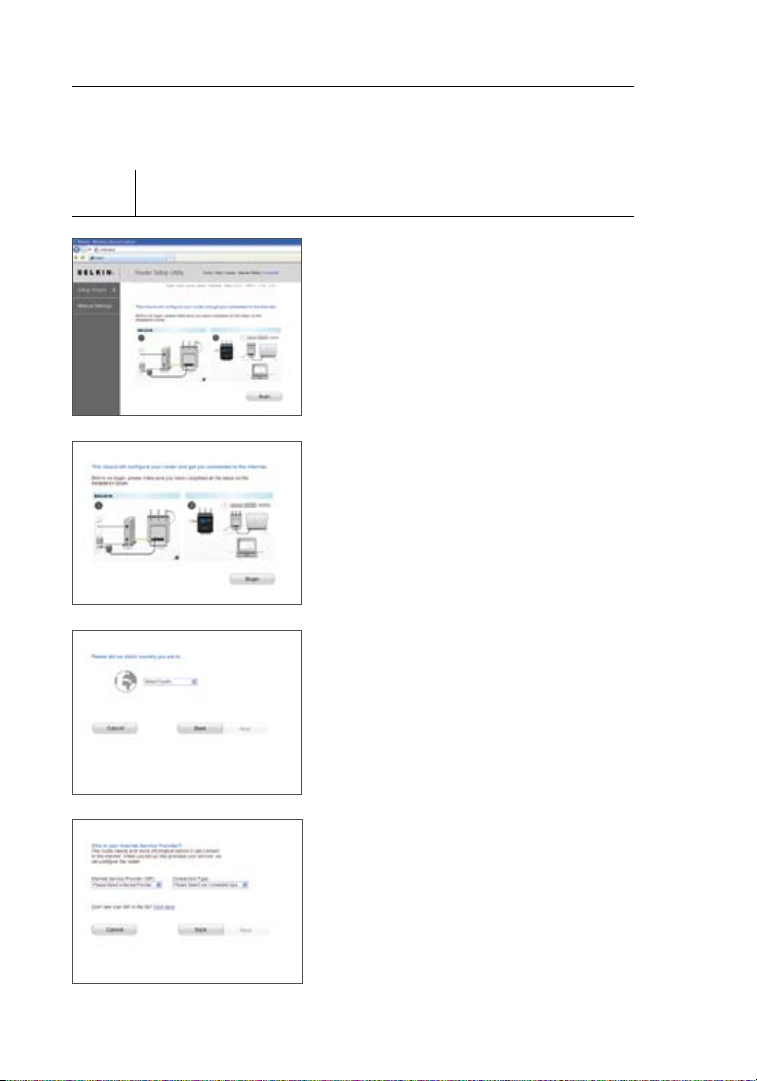
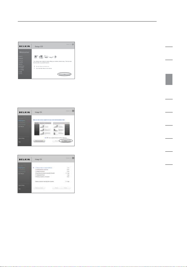
Step 2
Set Up the N1 Vision – Using the Plug-and-Play
Router Setup
A. Open a web brow ser on t hat
computer. T he Be lkin Router
Setup Wizard should app ea r
automati cally. If it doesn ’t,
enter “routersetup” into the
web-address fie ld an d p ress the
“Enter” key on your keyboard.
B. Th e Bel kin P lug-and-P la y S etup
Wizard should automa tically
appear. Verify that you have
complete d a ll QI G s te ps by
clicking “Begin” to continue.
Sel ec t t he co untry you are l ocated
C.
in by u sing the dro p-down box.
Click “Next” to continue.
D. Select your Internet Service
Pro vider (ISP) by using th e
dro p-down box. Click “N ex t” to
continue.
16
Connecting and Configuring your N1 Vision
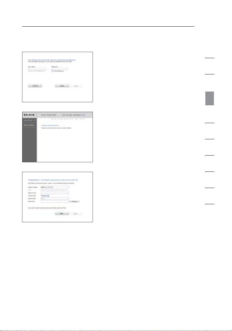
E. If your Internet account requires
a user name and passwo rd, you
will be taken to the screen below
to enter this infor ma tion. Click
“Next” to save and continue.
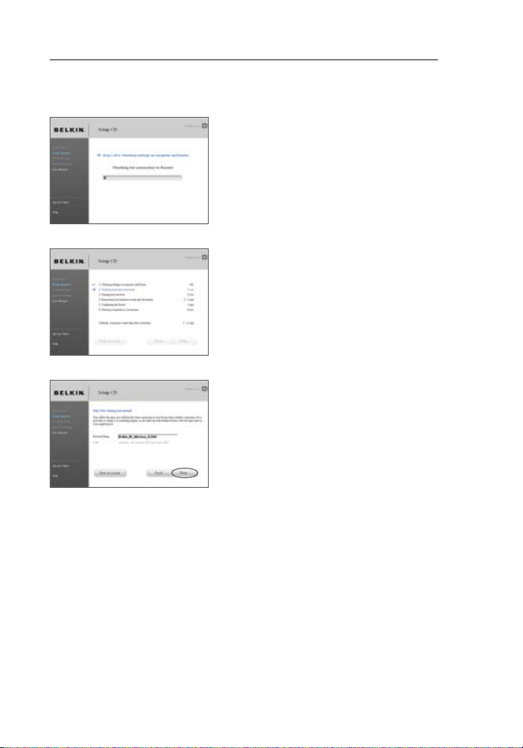
F. The N1 Vision will now check for
your Internet connection.
G. You w il l s ee th e C on gratula ti ons
screen when your N1 Vis ion can
connect to the Inte rnet. You have
finished in st alling your new Belk in
N1 Vis ion a nd can b egin surfing
by opening ano th er brow se r
and going to any websi te . You
may also choos e to cha ng e y ou r
network name, set up a wireless
security key, or enable the guest
mode from t his screen.
1
2
3
section
4
5
6
7
8
9
10
Options
1.
Network Name – This is the name of the N1 Vision.
2. Network Key Create a wire less securit y WPA key b y t yping any 8
to 63 a lphanum er ic ch aracters in lengt h. An y w irel ess d evices will
need this key to connect to the N1 Vision.
3. Guest Mode – When enab le d, th is mode will create a n ew
network to whi ch gu es t u sers can connect that wil l sep arate them
from access to your other network and connected devices.
1716
Connecting and Configuring your N1 Vision
1918
(4)
(6)
Interactive Display
The N1 Vision’s interactive display is a powerful instrument for
viewing you r n et work informati on. T he display can provide essent ia l
rou ter-status info rmation such as the state of the Inter net connec tion
to details such as each device usage and speed of the Internet
connecti on. W ithin the numerous featu res of the displa y, there are
also built-in help guides and tips for troubleshooting.
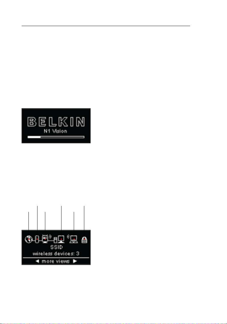
Startup Screen
Once the N1 Vi sion has been plugge d
in, the “Startup” screen will appear to
indicate th at th e N 1 Visio n is cur rent ly
in the boot-up state.
Information Screens
After the N1 Vision has finishe d s ta rting up and the Plug-and -P lay
Router Setu p p rocess ha s b ee n c om pleted, the first in a serie s of
informat ional screens will appear. Th es e s cree ns le t y ou vi ew yo ur
network status. Push the right key (>) or the left key (<) to cycle
through them. The following outlines the details on each.
(1)
(2)
(3)
(5)
A. Network Status
Once the N1 Vi sion has been
plugged in, th e “St ar tup” screen
will appear to indi ca te that the
N1 Vis ion i s c urre ntly in the
boot-up state.
18
Connecting and Configuring your N1 Vision
OFF Not connected to a modem
Solid White N1 Vis ion i s c onnected to modem an d
functioning properly
Blinking White Problem with modem (such as boot
failure, etc
.)
3. N1 Vision (Router) Wireless State
This icon indicates whether or not wireless is enabled.
N1 Vis ion s howing wireless
connecti on (w ith curved-l in es
illustra tion)
N1 Vis ion i s O N w it h w irel ess
enabled and ready fo r u se with
wireless and wired devices
N1 Vision showing wired
connection (without curvedlines illustration)
N1 Vis ion i s O N w it h w irel ess
disabled an d ready for use
with only wired devices
4. Wired Computers
This icon indicates if there are any wired connections present.
OFF Wired device not present
Solid White Wired device(s) conn ected to the
N1 Vision
1. Internet Connection
This icon shows you when the N1 Vision is connected to
the Internet.
OFF No Intern et connectio n has
been detected
Solid White N1 Vision is connected to the Internet
Blinking White Internet connectio n w as de tected;
N1 Vision is not currently able to
connect to the Internet
2. Modem Connection
This icon shows you when the N1 Vision is connected to
the modem.
1
2
3
section
4
5
6
7
8
9
10
1918
Connecting and Configuring your N1 Vision
2120
OFF Wireless device is not present
Solid White Wireless device (s ) i s c on nected to the
N1 Vision
6. Security
This icon indicates wireless security.
OFF Wireless security is OFF
Solid White Wireless security is ON
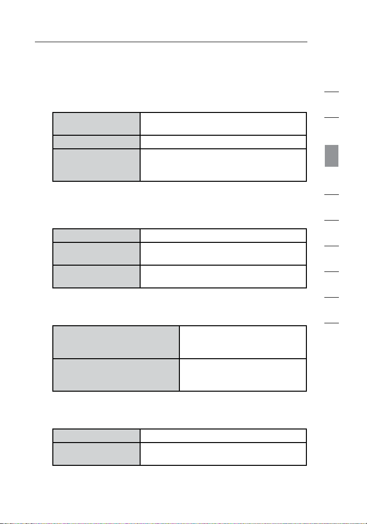
B. Broadba nd Do wn load
Speedometer
This screen will display the
current download speed being
transfer red through the Int er net
connecti on. T he speed will be
measured on the speedom et er
against the fastest speed that has
been measured by the N1 Vi sion
since being activated.
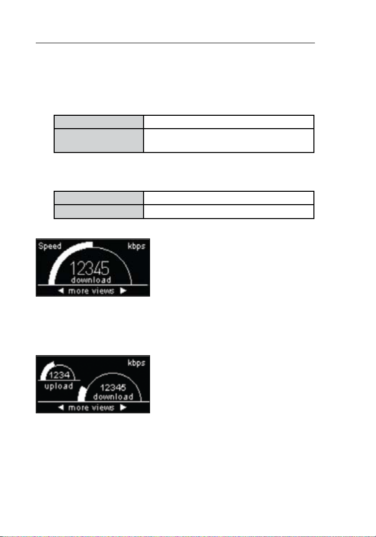
C. Broadb an d U pload/Dow nl oad
Speedometer
This screen will display the
current upload and down lo ad
speed being tr an sferred t hrou gh
the Internet connection. The
speed will be measu red on
the speedom et er against the
fastest spe ed th at ha s b een
measured by the N1 Vision since
being activated.
5. Wireless Computers
This icon repre sents if there are any wi rele ss
connections present.
20
Connecting and Configuring your N1 Vision
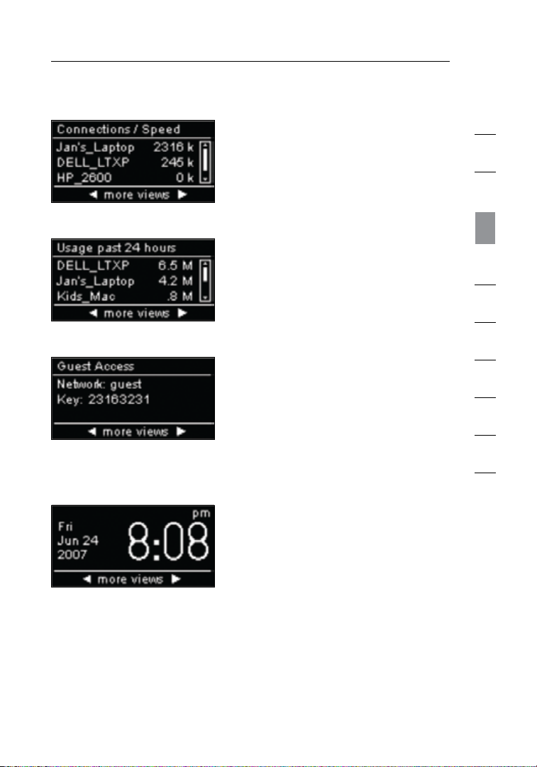
D. Connections/Speed
This screen displays al l d ev ices
currently conne ct ed to th e N 1
Vis ion and the speed of the
broadband data that is being
download ed or up loaded per
each device.
E. Usage Past 24 Hours
This screen displays al l d ev ices
currently conne ct ed to th e N 1
Vision and their broadband usage
over a period of 24 hours.
F. Guest Access Status
This screen indicate s w he ther
Guest Acces s i s ena bl ed or
disabled . F or mo re info rm ation on
the Guest-A cc ess feature, please
see the “Using the Web-Based
Advanced Us er In terface” secti on
in this User Manual.
G. Date & Time
This screen displays th e d at e a nd
time. To toggle between standard
and military time, push the up or
down key.
1
2
3
section
4
5
6
7
8
9
10
2120
Connecting and Configuring your N1 Vision
2322
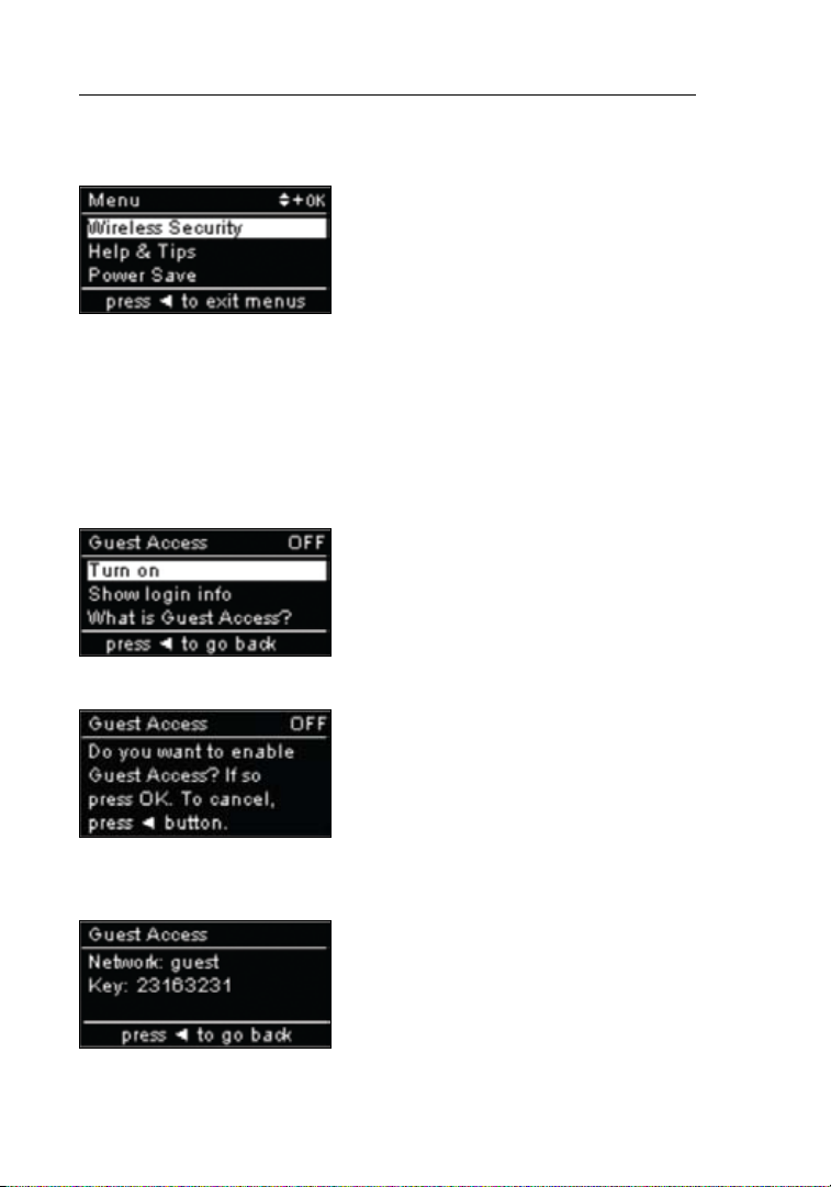
Menu Screen
Push the “Menu” button to open the
display’s Menu options. The Menu
option allo ws yo u t o e na ble f eatures
within the N1 Vision. The follo wi ng
outlines th e d et ails of each feature
within the Menu section.
A. Wireless Security
Select Wireless Secu rity by pres sing the “OK” button to view
these options. From the Wireless Security options, the choices
available are listed below.
Guest Acces s – Sele ct th is op tion to
enable a separate network to allow
guests to connect to the Internet while
keeping them away from accessing
your network, computers, and
private files.
Select “Turn On” to enable Guest
Access. To enable the Guest-Access
mode, you will need to enab le Wi -Fi
Protected AccessTM (WPATM) on
your private network first. To do so,
please see the “Setting WPA Security”
section in this User Manual.
To view the Guest Access network
name and passw ord, sele ct th e “ Sh ow
login info” op ti on.
22

Connecting and Configuring your N1 Vision
Push Button Security – Select this
option if you would like to set up your
computer s o r d ev ices using the Wi-Fi
Protected SetupTM ( WPS) standard.
Using WPS is not a req uire ment to
connect to the N1 Vision.
To make a WPS connection, select
the “New Connection” option. To do
so, you must have WPS enabled on
the compute r o r dev ic e c onnecting to
the N1 Vi si on. You wi ll ne ed to pu sh
the WPS button in your computer or
device within two minutes.
B. Help and Tips
Select this option for additional
information.
C. Power Save
Select this option to conserve the
display’s power or if you pre fer
to turn off graphic s. Wh en po wer
save is ON, the display will turn
off wi thin two minutes aft er an y
user interaction.
1
2
3
section
4
5
6
7
8
9
10
2322

Connecting and Configuring your N1 Vision
2524
Troubleshooting Assistant CD
Belkin h as provided o ur Assistan t software to m ake insta ll ing your
N1 Vision a simple an d easy task . You can use i t to get yo ur N1
Vis ion up an d running i n minutes . The Ass is tant soft wa re req ui re s
that you r Windows 2 000, XP, or Vista comp ut er be con ne cted
directly to your cable or DSL modem and that the Internet
connection is active and working at the time of installation. If it
is not, you must us e the “Al te rna te Setup Me th od” secti on in thi s
User Man ual to co nf igure your N1 Vis io n. Additi onally, if you a re
using an operatin g system ot he r than Wi ndows 200 0, XP, or Vis ta ,
you must set up t he N1 Vision us in g the “ Al terna te Setup Me th od”
section in this User Manual.
A. Shut down any programs that are running on your computer
at this time.
Tur n o ff any firewall or Inter net-con nection-s ha ring software on
your computer.
B. Insert the CD into your computer. The Troubleshooting Assistant
will automa ti cally appear on your comp uter’s screen wit hi n 1 5
seconds. Cl ic k o n “ Go ” t o r un th e Troub le shooting Ass is tant.
Follow the instructions there.
IMPORTANT: Run the Troubl es hooting A ss istant from the c omputer
that is directly connected to the Router from Step 1 – B.
24
Connecting and Configuring your N1 Vision
Select your language of choice and
click “Go” to run the
Troubleshooting Assistant.
Note for Windows Users: I f the
Troubleshoot ing A ssistant doe s
not start up automatically, select
your CD-ROM driv e f rom “My
Computer ” a nd do uble-clic k on the
file named “Se tu p.exe” to start the
Troubleshooting Assistant.
Confirmation Screen
Verify that you have comp le ted all QIG
steps by check in g t he bo x t o t he ri gh t
of the arrow. Click “Next” to continue.
Progress Screen
Troubleshoot ing A ssistant wil l sho w
you a p ro gres s s cree n eac h t im e a
step in the setup has been completed.
1
2
3
section
4
5
6
7
8
9
10
2524
Connecting and Configuring your N1 Vision
2726
1.1 Checking Settings
The Troubleshoo ti ng Assistant
will now examine your computer’s
network set ti ngs and gather
informat ion n eeded to complete
the N1 Vi si on’s con ne ction to
the Internet.
1.2 Verifying Hardware Connections
The Troubleshoo ti ng Assistant
will now verif y you r h ardw are
connection.
1.3 Naming your Wireless Network
The Troubleshoo ti ng Assistant
will display the default wireless
network nam e o r Ser vi ce Set
Identifi er (S SID). This is the name
of your wireless networ k t o whi ch
your comput er s o r d ev ices with
wireless networ k ada pters will
connect. You can either use the
default or change it to something
unique. Write down this name
for future reference. Click “Next”
to continue.
26

Connecting and Configuring your N1 Vision
1.4 Requesting Internet Account
Info (if needed)
If your Internet account requires
a login and password, you will
be pro mpted with a scre en similar
to the one on the left. Select
your country or ISP from the
drop-down boxes.
1.5 Configuring the N1 Vision
The Troubleshooting Assistant will
now configure your N1 Vision by
sending data to the N1 Vision
and restarting it. Wait for the
on-screen instructions.
Note: Do not disconnect any
cable or power off the N1 Vision
while the N1 Vision is rebooting.
Doing so will render your
N1 Vision inoperable.
1
2
3
section
4
5
6
7
8
9
10
2726

Connecting and Configuring your N1 Vision
2928
1.6 Checking Internet Connection
We are almost done. The
Troubleshoot ing A ssistant wil l
now check your connection to
the Internet.
Congratulations
You have finished installing your new
Belkin N1 Vision. You will see the
Congratulations screen when your N1
Vision can connect to the Internet.
You can begin surfing by opening your
browser and going to any website.
You can use the Troubleshooting
Assistant to set up your other wired
and wireless computers to connect to
the Internet by clicking “Next”. If you
decide to add computers to your N1
Vision later, select “Exit the Assistant”
and then click “Next”.
Troubleshooting
If the Troubleshooting Assistant is not
able to connect to the Internet, you will
see this screen. Follow the on-screen
instructions to go through the
troubleshooting steps.
28

Connecting and Configuring your N1 Vision
1.7 Op tional: Assi st ance Connect in g
Other Computers
This option al st ep wi ll help you
to connect add it ional wired
and wireless compute rs to yo ur
network. Fo ll ow the o n-screen
instructions.
Congratulations
Once you have verified that your other
wired and wireless computers are
properly connected, your network is set
up and working. You can now surf the
Internet. Click “Next” to return to the
main menu.
1
2
3
section
4
5
6
7
8
9
10
2928

Alternate Setup Method
3130
Step 1
Hardware Connections – Follow the
Quick Installation Guide (QIG)
See the QIG or Step 1: Hardware Connections from the
previous section.
Step 2 Set your Computer’s Network Settings to Work
with a DHCP Server
See the sectio n in thi s Use r M an ual c alled “Manua ll y C onfigurin g
Network Settings” for directions.
Step 3 Configuring the N1 Vision Using the Web-Based
Advanced User Interface
Using your Internet browser, you can access the N1 Vision’s
Web-Based Advanced User Interface. In your browser, type
“192.168.2.1”(donottypeinanythingelsesuchas“http://”or
“www”). Then press the “Enter” key.
30

Alternate Setup Method
Logging into the N1 Vision
You will see the N1 Vision’s home page in your browser window.
The home page is visib le to an y use r w ho wa nt s t o s ee it . To make
any changes to the N1 Vision’s s ettings, you have to log in. Clic ki ng
the “Login” bu tt on or cl icking on any one of the links on the home
page will take you to the logi n screen. The N1 Vision ships with no
password entered. In the login screen, leave th e p as sword b la nk and
click the “Submit” button to log in.
Logging out of the N1 Vision
One computer at a time can log into the N1 Vision for the purposes
of making chan ge s t o t he se tt ings of the N1 Vis io n. Once a u ser h as
logged in to make changes, there are two ways that the computer
can be logged out. Clicking the “Logout” button will log the
computer ou t. Th e s ec ond method is automa ti c. The l ogin will time
out after a specified period of time. The default login time-out is
10 minutes. Th is ca n b e cha ng ed from on e t o 99 min ut es. F or more
informat ion, see the section in this manu al ti tled “Changing th e Log in
Time-Out Setting”.
1
2
3
4
section
5
6
7
8
9
10
Understanding the Web-Based Advanced User Interface
The home page (show n o n the ne xt pa ge ) i s t he fi rst p age you will see
when you access the Advanced User Interface (UI). The home page
shows you a quick view of the N1 Vi sion’s s ta tus and settings. Al l
advanced setup pages can be reached from this page.
3130

Alternate Setup Method
3332
(1)
(2)
(9)
(8)
1. Quick-Navigation Links
You can go directly to any of the N1 Vision’s advanced UI
pages by clicking directly on these links. The links are divided
into logica l c at egories and grouped by tabs to make findin g a
particular setting easier to find. Clicking on the purple header of
each tab will show you a short description of the tab’s function.
2. Home Button
The home button is available in every page of the UI. Pressing
this button will take you back to the home page.
3. Internet-Status Indicator
This indicator is visible in all pages of the N1 Vision, indicating
the connect io n s tatus of the N1 Vi si on. W hen the indicator sa ys
“Connected” in gray, the N1 Vision is connected to the Internet.
When the N1 Vi sion is not c onnecte d to the Inte rnet, the ind ic ator
will read “No Connection” in red. The indicator is automatically
updated when you make changes to the settings of the N1 Vision.
4. Login/Logout Button
This button en ab les y ou to lo g i n a nd ou t o f t he N1 Vision with
the press of one button. When you are logged into the N1 Vision,
this button wi ll ch an ge to read “L og out”. Logging int o the N1
Vision will take you to a separate login page where you will need
(5) (4) (3)
(10)
(7)
(6)
32

Alternate Setup Method
to enter a password. When you are logged into the N1 Vision,
you can make changes to the settings. When you are finished
making changes, you can log out of the N1 Vision by clicking the
“Logout” bu tt on. For more in formation abou t l og ging into the N1
Vision, see the section called “Logging into the N1 Vision”.
5. Help Button
The “Help” but to n g iv es you a ccess to the N1 Vi si on’s hel p
pages. Help is also av ai lable on many pages by clickin g “ mo re
info” next to certain sections of each page.
6. LAN Settings
Shows you the settings of the Local Area Network (LAN) side of
the N1 Vision. Changes can be made to the settings by clicking
on any one of the links (IP Address, Subnet Mask, DHCP Server)
or by clicking the “LAN” quick-navigation link on the left side of
the screen.
7. Features
Shows the stat us of th e N1 Vision’s N AT, firewal l, an d w irel es s
features. Chang es ca n b e m ad e t o t he se tt ings by clicking on any
one of the links or by clickin g the qu ic k-navigat io n l inks on the
left side of the screen.
8. Internet Settings
Shows thesett in gs of th eI nt ernet /WAN side of the N1 Vision that
connects to the Internet. Changes to any of these settings can
bemadebyclickingonthelinksorbyclickingonthe“Internet/
WAN” quick-navigation link on the left side of the screen.
9. Version Info
Shows the firm wa re vers io n, boot-code vers ion, hard ware
version, and serial number of the N1 Vision.
10. Page Name
The page you are on ca n b e i de ntified by this name. Thi s Use r
Manual will so me times ref er to pa ges by n ame. For instance
“LAN > LAN Settings” refers to the “LAN Settings” page.
1
2
3
4
section
5
6
7
8
9
10
3332

Alternate Setup Method
3534
Step 4
Configuring your N1 Vision for Connection to your
Internet Service Provider (ISP)
The “Internet/WAN”tab is wherey ou wi ll setu py ourN 1Visio nt o
connect to you r Int er net Serv ic e P rovi der ( ISP). The N1 Vi si on is
capable of con ne cting to virtuall y any IS P’s system provided yo u hav e
correctly confi gu re d the N1 Vision’s settings for your IS P’s connec ti on
type. Your ISP connecti on se ttings are p rovi ded t o y ou by yo ur IS P.
To configure the N1 Vision with the settings that your ISP gave you,
click “Connection Type” (A) on the left side of the screen. Select
the connect io n t ype y ou use. If your ISP gave you DNS settings ,
clicking “DNS” (B) allows you to enter DNS address ent ri es for I SPs
that require specific settings. Clicking “MAC Address” (C) will let you
clone your computer’s MAC address or type in a specific WAN MAC
address, if req uire d b y y ou r I SP. Wh en yo u h ave f inished maki ng
settings , t he “I ntern et St atus” indicato r w il l read “co nn ection OK” if
your N1 Vision is set up properly.
(A)
(B)
(C)
34

Alternate Setup Method
Setting your Connection Type
From the “Connection Type” page, you can select the type of connection
you use. Select the type of connection you use by clicking the button (1)
next to your connection type and then clicking “Next” (2).
(1)
(2)
1
2
3
4
section
5
6
7
8
9
10
3534

Alternate Setup Method
3736
(3)
Setting your Internet Service Provider (ISP) Connection
Type to Dynamic IP
A dynamic connection type is the most common connection type found with
cable modems. Setting the connection type to “dynamic” in many cases is
enough to complete the connection to your ISP. Some dynamic connection
types may require a host name. You can enter your host name in the space
provided if you were assigned one. Your host name is assigned by your ISP.
Some dynamic connections may require that you clone the MAC address of
the PC that was originally connected to the modem.
1. Host Name
This space is provided to enter a host nam e tha t n ee ds to be
visible to you r ISP. E nt er your host name here and c lick “Apply
Changes” (3). If your ISP did not assign you a host name, or you
are not sure, leave this blank.
2. Change WAN MAC Address
If your ISP re quires a s pe cific MAC address to connect to the
service, yo u c an en te r a sp ec ific MAC address or clone the
current computer’s MAC address through this link.
(1)
(2)
36

Alternate Setup Method
(3)
Setting your Internet Service Provider (ISP) Connection Type to Static IP
A static IP address connec ti on ty pe is le ss common than other
connecti on ty pes. If your ISP uses static IP addressi ng , y ou wi ll
need your IP address, subn et ma sk , a nd IS P g ateway address. This
information is available from your ISP or on the paperwork that your
ISP left with you. Type in your info rm ation, then click “Apply Chan ge s”
(5). After you apply the changes, the Internet Status indicator will
read “connection OK” if your N1 Vision is set up properly.
1. IP Address
Enter the IP address that has been provided by your ISP here.
2. Subnet Mask
Enter the subnet mask that has been provided by your ISP here.
3. ISP Gateway Address
Enter the gateway address that has been provided by your ISP here.
4. My ISP Provides More Than One Static IP Address
If your ISP assigns you more than one static IP address, your N1
Vis ion is c apable of handl in g u p t o fiv e s ta tic WAN IP addresses.
Select “My ISP provides mo re than one stati c I P add ress ” a nd
enter your additional addresses.
(1)
(2)
(4)
1
2
3
4
section
5
6
7
8
9
10
(5)
3736

Alternate Setup Method
3938
Setting your ISP Connection Type to PPPoE
Most DSL providers use PPP oE as th e con ne ction type. If you use a
DSL modem to connect to the Internet, your ISP may use PPPoE to
log you into the service. If you have an Internet connection in your
home or small office that doesn’t require a modem, you may also
use PPPoE.
Your connection type is PPPoE if:
1) Your ISP gave you a user name and password, which is required
to connect to the Internet.
2) Your ISP gave you software such as WinPOET or Enternet300
that you use to connect to the Internet.
3) You ha ve to do ub le-clic k on a deskto p i co n o th er than your
browser to get on the Internet.
38

Alternate Setup Method
(5)
1
2
(1)
(2)
(3)
(4)
1. User Name
This space is provided to type in your user name that was
assigned by your ISP.
2. Password
Type in your password and retype it into the “Retype Password”
box to confirm it.
3. Service Name
A service name is rarely required by an ISP. If you are not sure if
your ISP requires a service name, leave this blank.
4. MTU
The MTU setting should never be changed unless your ISP gives
you a s pecific MTU set ti ng. M aking change s to the MTU set ti ng
can cause problems with yo ur In te rnet con ne ction includ in g
disconne ction fro m t he In terne t, sl ow Inter ne t a ccess, and
problems with Internet applications working properly.
5. Disconnect after X...
The “Discon ne ct” feature is used to automatic al ly disconnec t the
N1 Vis ion f ro m y ou r I SP wh en th ere i s no act iv ity f or a s pe cified
period of time. For inst ance, placing a check mar k nex t t o thi s
option and ent er ing “ 5” into the minute field wil l cau se th e N 1
Vis ion to d isconnect from the Inter net after five min ut es of no
Internet activity. This option shoul d b e use d i f you pa y for yo ur
Internet service by the minute.
3
4
section
5
6
7
8
9
10
3938

Alternate Setup Method
4140
Setting your Internet Service Provider (ISP) Connection Type to
Point-to-Point Tunneling Protocol (PPTP)
[European countries only]
Some ISPs require a c on nection usin g P PT P p roto co l, a t yp e o f
connecti on mo st common in European countri es. T his sets up a di re ct
connecti on to th e I SP ’s syste m. Type in the infor ma tion prov ided
by your ISP in the space provided. When you hav e fin ished, click
“Apply Changes”
Status indi ca tor will rea d “ connectio n OK” if your N1 Vision is set
up properly.
(9). After you apply the chang es , t he In terne t
(1)
(2)
(3)
(4)
(5)
(6)
(7)
(8)
(9)
1. PPTP Account
Enter the PPTP acco un t n ame t hat has been provided by your
ISP here.
2. PPTP Password
Type in your password and retype it into the “Retype Password”
box to confirm it.
3. Host Name
Enter the host name that has been provided by your ISP here.
4. Service IP Address
Enter the service IP address that has been provided by your ISP here.
5. My IP Address
Enter the IP address that has been provided by your ISP here.
40

Alternate Setup Method
6. My Subnet Mask
Enter the subnet mask that has been provided by your ISP here.
7. Connection ID (optional)
If your ISP has pro vided you with a connec ti on ID , e nter it here .
If not, you can leave this blank.
8. Disconnect after X....
The “Discon ne ct” feature is used to automatic al ly disconnec t the
N1 Vis ion f ro m y ou r I SP wh en th ere i s no act iv ity f or a s pe cified
period of time. For inst ance, placing a check mar k nex t t o thi s
option and ent er ing “ 5” into the minute field wil l cau se th e N 1
Vis ion to d isconnect from the Inter net after five min ut es of no
Internet activity. This option shoul d b e use d i f you pa y for yo ur
Internet service by the minute.
1
2
3
4
section
5
6
7
8
9
10
4140

Alternate Setup Method
4342
(4)
(5)
(3)
(6)
1. Select your State
Select your state from the drop-down menu (1). The “Login
Server” box wi ll au to matically be fill ed in wi th an IP ad dres s.
If for some re ason this address does not match the add ress
that Telstra has given, you can manu ally enter the login serv er
address. See “User decide login server manually” (4).
2. User Name
Type in the user name that has been provided by your ISP here.
3. Password
Type in your password and retype it into the “Retype Password”
box to confirm it.
Setting your Connection Type if you are a Telstra® BigPond User
[Australia Only]. Your user name and password are provided to you by
Telstra BigPond . Ent er th is informati on be lo w. C ho osing your state
from the drop-down menu
IP address. If your login serve r a dd re ss is di fferent than one provided
here, you m ay manually ent er th e l og in se rver IP address by p lacing a
check in the box next to “User decide login server manually”
type in the address next to “Login Server”
all of your information, click “Apply Changes”
changes, th e I nt ernet Stat us in dicator will read “conne ct ion OK” if
your N1 Vision is set up properly.
(1) w ill a utomati ca lly f ill in y our login server
(4) a nd
(5). When you have entered
(6). After you apply the
(1)
(2)
42

Alternate Setup Method
4. User Decide Login Server Manually
If your login server IP address is not available in the “Select Your
State” drop-down menu (1), you may manually enter the login
server IP address by placi ng a che ck in th e box ne xt to “U se r
decide logi n s er ver m anually” and type in the add ress next to
“Login Server” (5).
Setting Custom Domain Name Server (DNS) Settings
A “Domain Name Server” is a server located on the Internet that translates
Universal Resource Locaters (URLs) like “www.belkin.com” to IP addresses.
Many Internet Service Providers (ISPs) do not require you to enter this
information into the N1 Vision. The “Automatic from ISP” box (1) should
be checked if your ISP did not give you a specific DNS address. If you are
using a static IP connection type, then you may need to enter a specific
DNS address and secondary DNS address for your connection to work
properly. If your connection type is dynamic or PPPoE, it is likely that you
do not have to enter a DNS address. Leave the “Automatic from ISP” box
checked. To enter the DNS address settings, uncheck the “Automatic from
ISP” box and enter your DNS entries in the spaces provided. Click “Apply
Changes” (2) to save the settings.
(1)
(2)
1
2
3
4
section
5
6
7
8
9
10
4342

Alternate Setup Method
4544
Configuring your WAN Media Access Controller (MAC) Address
All network components including cards, adapters, and routers, have
a unique “serial number” called a MAC address. Your Internet Service
Provider (ISP) may record the MAC address of your computer’s adapter
and only let that particular computer connect to the Internet service.
When you install the N1 Vision, its own MAC address will be “seen” by
the ISP and may cause the connection not to work. Belkin has provided
the ability to clone (copy) the MAC address of the computer into the N1
Vision. This MAC address, in turn, will be seen by the ISP’s system as
the original MAC address and will allow the connection to work. If you
are not sure whether your ISP needs to see the original MAC address,
simply clone the MAC address of the computer that was originally
connected to the modem. Cloning the address will not cause any
problems with your network.
Cloning your MAC Address
To clone your MAC address, make sure that you are using the computer
that was ORIGINALLY CONNECTED to your modem before the N1 Vision
was installed. Click the “Clone” button
Your MAC address is now cloned to the N1 Vision.
Entering a Specific MAC Address
In certain circumstances you may need a specific WAN MAC address.
You can manually enter one in the “MAC Address” page. Type in a
MAC address in the spaces provided
to save the changes. The N1 Vision’s WAN MAC address will now be
changed to the MAC address you specified.
(1). Click “Apply Changes” (3).
(2) and click “Apply Changes” (3)
44
(2)
(1)
(3)

Alternate Setup Method
Using your Internet browser, you can access the N1 Vision’s Web-Based
Advanced User Interface. In your browser, type “192.168.2.1” (do not
typeinanythingelsesuchas“http://”or“www”)thenpressthe
“Enter” key.
You will see the N1 Vision’s home page in your browser window.
Viewing the LAN Settings
Clicking on the header of the LAN tab
header page. A quick description of the functions can be found here. To
view the settings or make changes to any of the LAN settings, click on
“LAN Settings”
“DHCP client list”
(1)
(2)
(3)
(2) or to view the list of connected computers, click on
(3).
(1) will take you to the LAN tab’s
1
2
3
4
section
5
6
7
8
9
10
4544

Using the Web-Based Advanced User Interface
4746
(3)
1. IP Address
The “IP address” is the internal IP address of the N1 Vision. The
default IP address is “192.168.2.1”. To access the advanced setup
interface, type this IP address into the address bar of your browser.
This address can be changed if needed. To change the IP address,
type in the new IP address and click “Apply Changes”. The IP
address you choose should be a non-routable IP. Examples of a
non-routable IP are:
192.168.x.x (where x is anything between 0 and 255)
10.x.x.x (where x is anything between 0 and 255)
2. Subnet Mask
There is no need to change the subnet mask. This is a unique,
advanced feature of your Belkin N1 Vision. It is possible to change
the subnet mask if necessary; however, do NOT make changes to
the subnet mask unless you have a specific reason to do so. The
default setting is “255.255.255.0”.
Changing LAN Settings
All setting s f or th e i nt ernal LAN set up of th e N 1 Vision can be view ed
and changed here.
(1)
(2)
(4)
(5)
(6)
46

Using the Web-Based Advanced User Interface
3. DHCP Server
The DHCP server function makes setting up a network very easy
by assigning IP addresses to each computer on the network
automatically. The default setting is “On”. The DHCP server can
be turned OFF if necessary; however, in order to do so you must
manually set a static IP address for each computer on your network.
To turn off the DHCP server, select “Off” and click “Apply Changes”.
4. IP Pool
The range of IP addresses set asid e for dy na mic a ssignment
to the compute rs on yo ur ne tw ork. The default is 2–100 (9 9
computer s). I f y ou wa nt to ch ange this number, yo u can do so
by entering a new star ti ng an d e nding IP address and clicking on
“Apply Changes”. The DHCP server can assign 100 IP addresses
automati cally. Thi s m ea ns that you cannot specif y a n IP add ress
pool larger than 100 computers. For example, starting at 50
means you have to end at 150 or lower so as not to exceed the
100-client limit. The starting IP address must be lower in number
than the ending IP address.
5. Lease Time
The length of time the DHCP server will reserve the IP address
for each compu te r. We recomme nd th at yo u l ea ve the l ease
time set to “Forever”. The default setting is “Forever”, meaning
that any time a computer is assigned an IP address by the
DHCP server, the IP address wil l not ch an ge for t hat particul ar
computer. S et ting lease times for shor ter i ntervals suc h as one
day or one hour frees IP addresses after the specified period of
time. This als o mea ns th at a p ar ticular comput er’s IP address
may change over time. If you have set any of the other advanced
features of the N1 Vi si on such as DMZ o r c lient IP filters, th es e
are dependent on the IP address. For this reason, you will not
want the IP address to change.
6. Local Domain Name
The default setting is “Belkin”. You can set a local domain name
(network name) for your network. There is no need to change
this settin g u nl ess y ou have a s pecific advanc ed ne ed to do so .
You can name the network anything you want such as
“MY NETWORK”.
1
2
3
4
5
section
6
7
8
9
10
4746

Using the Web-Based Advanced User Interface
4948
(3)
Viewing the DHCP Client List Page
You ca n v ie w a li st of th e c om puters (known as clien ts), which are
connected to your network. You are able to view the IP address
the computer, the host name
one), and the MAC address
card (NIC). Pressing the “Refresh”
there have been any changes, the list will be updated.
(2) (if the computer has been assigned
(3) o f t he co mputer’s n etwork interfa ce
(4) button will update the list. If
(1) o f
(1) (2)
(4)
Configuring the Wireless Network Settings
The “Wireless” tab lets yo u mak e c ha nges to the w irel ess network
settings. From this tab you can make changes to the wireless network
name or Service Set Identifier (SSID), operating channel, encryption
security settings, and configure the N1 Vision to be used as an
access point.
48

Using the Web-Based Advanced User Interface
Changing the Wireless Network Name (SSID)
To ide ntify your wireless networ k, a nam e c al led the SSID is us ed.
The SSID is your netwo rk na me . T he de fault networ k nam e o f the N1
Vis ion is “ Belkin N1 Wireless” foll ow ed by si x d igits that are un ique to
your N1 Vision. Your network name will look something like
“Belkin_ N1_Wireless_1 23 456”. You ca n c ha nge this to anything yo u
choose, or you can lea ve it un ch anged. Keep in mind, if you decid e
to change your wireless ne tw ork n ame, and there are oth er wi re le ss
networks operating in your area, your network name needs to be
different from other wireless networks that may be operating in your
are a. To chan ge th e S SI D, type in the S SID that you want to use
in the SSID field
immediat e. If yo u m ak e a ch an ge to th e S SID, your wireless-eq ui pped
computer s m ay al so ne ed to be reco nf igured to co nnect to your new
network nam e. Re fer t o t he do cumentati on of yo ur wi re le ss network
adapter for information on making this change.
(1) and click “Apply Changes” (2). The change is
(1)
1
2
3
4
5
section
6
7
8
9
10
(2)
Note: P lease period ic ally check for new N1 Vis ion firmware updates
fro m t he “U tilities > Firm wa re upda te ” p age. Newer firmwa re can fix
problems,addwirelessfeatures,and/orimprovewirelessperformance
(see page 75).
4948

Using the Web-Based Advanced User Interface
5150
IEEE 802.11b or 802.11g operation of this product in the U.S.A.
is firmware-limited to channels 1 through 11.
Changing the Wireless Channel
There are a number of operating channels from which you can
choose—in the United States, there are 11 and in the United Kingdom
(and most of Europe), there are 13. In a small number of other countries,
there are other channel requirements. Your N1 Vision is configured to
operate on the proper channels for the country in which you reside. The
channel can be changed if needed. If there are other wireless networks
operating in your area, your network should be set to operate on a
channel that is different than the other wireless networks.
Using the Wireless Mode Switch
This switch allows you to set the N1 Vision’s wireless modes. There are
several modes.
Note: Some modes may require firmware updates to be enabled.
1) 802.11b+g+n
Setting the N1 Vision to this mode will allow 802.11b-, 802.11g-, and
802.11n-compliant devices to join the network.
2) Off
This mode will turn OFF the N1 Vision’s access point, so no
wireless device s can jo in th e n et work. Turn ing o ff th e wireles s
function of your N1 Vision is a great way to secure your network
when you are a way f ro m h om e f or a lon g p er iod o f t ime, or don’t
want to use the wireless feature of the N1 Vision at a certain time.
50

Using the Web-Based Advanced User Interface
Using the Bandwidth Switch
This switch allows you to set the N1 Vision’s wireless bandwidth modes.
There are several modes available:
1) 20MHz only
Setting the N1 Vision to this mode allows only 20MHz operatio n.
This mode is compatible with N1, draft 802.11n-, 802.11g-, and
802.11b-compliant devices, but will limit N1, draft 802.11n-compliant
devices’ bandwidth b y half. Reducing bandwidth to 20MHz-only
operation might solve some wireless problems.
2) 20MHz/40MHz Auto
Setting the N1 Vision to this mode allows it to switch automatically
between 20MHz and 40MHz operation. This mode enables 40MHz
operation, to maximize speed for N1, draft 802.11n-compliant
devices whe n c on ditions permit . W he n a le ga cy 802.11g
access poin t i s present ed an d o cc upies an adjacent se co ndary
channel, th e N 1 Vision aut om atically reverts to 20MHz ope ra tion
to maximize compatibility. We recommend using this as the
default mode.
1
2
3
4
5
section
6
7
8
9
10
5150

Using the Web-Based Advanced User Interface
5352
Using the Broadcast SSID Feature
Note: This advanced feature should be employed by advanced users
only. For security, you can choose not to broadcast your network’s SSID.
Doing so will keep your network name hidden from computers that are
scanning for the presence of wireless networks. To turn off the broadcast
of the SSID, remove the check mark from the box next to “Broadcast
SSID”, and then click “Apply Changes”. The change is immediate. Each
computer now needs to be set to connect to your specific SSID; an SSID
of “ANY” will no longer be accepted. Refer to the documentation of your
wireless network adapter for information on making this change.
Protected Mode Switch
Protected mode ensures proper operation of N1, draft 802.11n-compliant
devices on your wireless network when 802.11g or 802.11b devices
are present or when there is heavy 802.11g or 802.11b traffic in the
operating environment. Use protected mode if your network consists of
a mix of Belkin N1 Wireless Cards and 802.11g or 802.11b cards on your
network. If you are in an environment that includes little to no 802.11g
or 802.11b wireless network traffic, you will achieve the best N1 wireless
performance with protected mode OFF. Conversely, in an environment
with HEAVY 802.11g or 802.11b traffic or interference, you will achieve
the best N1 wireless performance with protected mode ON. This will
ensure N1 wireless performance is not affected.
Changing the Wireless Security Settings
Your N 1 Visio n is equ ip ped with the latest secur ity s tandard called
Wi-Fi Protected Access™ 2 (WPA2™) and t he legacy secur it y s ta ndard
called Wired Equival ent P rivacy (WEP) . Your N1 Vi sion also support s
the Wi-Fi Protected Set up (W PS) s pecificat ion, which simpli fi es the
setup of a wireless networ k. WP S use s f am iliar method ol ogies, such
as typing in a Personal Identification Number (PIN) or pushing a
button, to ena bl e u se rs to au tomatical ly co nfigure network names
and strong WPA/W PA2dataencr yp tion andauthenti ca tion.By
default, your N1 Vision does not ship with security enabled. You may
automati cally configure the securi ty se ttings using WPS. To change
the security settings manually, you will need to determine which
standard you want to use. To access the security settings, click
“Security” on the “Wireless” tab.
52

Using the Web-Based Advanced User Interface
(3)
Using Wi-Fi Protected Setup
WPS uses WPA2 (descri bed below) for encrypti on. It doe s not
provide additional security, but rather, standardizes the method for
sec uring your wire less network. You m ay use eit her the Pu sh But ton
Con figuration (P BC) method or PIN me thod to al low a devi ce access to
your wireless network. Conceptually, the two methods work as follows:
PBC: Push the “Menu” button on the front of your N1 Vision and
select “Wireless Security” from the options. Next select “Push
Button Security”, then initiate the WPS process by selecting “New
Con nection”. To co mplete the WPS procedure, the client dev ice
wil l need to connect wi thin two m inutes. Refer to your client’s
documentation on this procedure. Pushing the PBC button will
aut omatically en able WPS. The client has now b een securely ad ded to
your wireless network.
PIN: The clien t dev ic e h as a P IN nu mb er (either four or eigh t
digits) that is associated with WPS. Enable WPS through the
screen illustra te d b elow. Enter the client’s P IN into the N1 Vis io n’s
internal re gi strar (acces se d t hrou gh th is scre en). The client will be
automatically enrolled into your wireless network within two minutes.
(1)
1
2
3
4
5
section
6
7
8
9
10
(2)
(4)
(5)
5352

Using the Web-Based Advanced User Interface
5554
1. Wi-Fi Protected Setup (WPS): Enabled or Disabled.
2. Personal Identification Number (PIN) Method: In this method,
a wireless client wishing to access your network must supply
a 4- or 8-digit PIN to the N1 Vision. After clic king “Enroll”, you
mus t start th e WPS hand shaking procedure from the client within
two minutes.
3. Router PIN: If an exte rnal re gistrar is availa ble, you may enter in
the N1 Vision’s PIN to the registrar. Click “Generate New PIN”
to change the PIN from the default value. Click “Restore Default
PIN” to reset the PIN value.
4. Push Button Co nf iguration (PBC ) M et hod: PBC is an
alternate method to connect to a WPS network. Push the
“Start PBC” bu tt on an d t hen i nitiate the PBC on the clien t
device. Alt er nativ ely, push the “Sta rt PB C” so ft button to
start this process.
5. Manual Conf ig uration Meth od : T his s ection lists the def au lt
security settings if not using WPS.
The N1 Vi si on features WPA2, wh ic h i s t he se cond generatio n o f the
WPA™ based 802.11i standard. It offers a higher level of wireless
security by co mb ining advanced ne tw ork authenti ca tion and stronger
Advanced Encryption Standard (AES) encryption methods.
54

Using the Web-Based Advanced User Interface
WPA2 Requirements
IMPORTANT: In order to use WPA2 secu ri ty, all your com pu ters and
wireless client adap ters must be upgraded wit h pat ches, driver, and
client util it y s oftware t hat supporte d WPA2. At the time of this User
Manual’s publication, a couple security patches are available, for
free download, from Microsoft®. These patche s wor k o nl y w it h t he
Windows XP ope ra ting system. Othe r ope rating systems are not
supported at this time.
For Windows XP comp ut ers that do not have Service Pack 2
(SP2), a file from Microsoft called “W in dows XP Support Patch
for Wireless Protected Access (KB 826942)” is available for free
downloadathttp://support.microsoft.com/?kbid=826942
For Windows XP with Se rv ice P ack 2, M icro soft has rel eased
a free download to update the wireless client components to
support WPA2 (KB893357)
http://support.microsoft.com/?kbid=893357
IMPORTANT: You also need to ensure that all your wireless client
cards/adapte rs su pportWPA2 ,a nd th at youh avedownload ed an d
installed the latest driver. Most of the Belkin wireless cards have
driver upda te s a vailable for down lo ad from th e Bel kin s upport site:
www.belkin.com/networking.
. The update is available from:
1
2
3
4
5
section
6
7
8
9
10
5554

Using the Web-Based Advanced User Interface
5756
Setting WPA/WPA2-Personal (PSK)
Like WPA sec urity, WPA2 is a vailabl e in WPA2-Perso na l ( PSK) mode.
Typically, WPA2-Personal (PSK) is the mode that will be used in a
home environmen t. Th is gu ide will focus on WPA2-Persona l (PS K)
usage. Plea se refer to the User Ma nu al fo r m ore inf or mation about
wireless security and different types of wireless security.
1. After you’ve set up your N1 Vision, go to the “Security” page
under“Wireless”andselect“WPA/WPA2-Personal(PSK)”fromthe
“Security Mode” drop-down menu.
2. For “Authen ti cation”, sel ec t “ WPA-P SK ”, “W PA2-P SK”, or
“WPA-PSK + WPA2-PSK”. This setting will have to be identical
on the wireless clients that you set up. “WPA-PSK + WPA2-PSK”
mode will allo w the N1 Vision to suppor t c li ents running eith er
WPA or WPA2 security.
4. Enter your pre-shared key (PSK). Th is ca n b e from eight to 63
characte rs an d c an be le tters, numbers , o r sym bols. This same
key must be used on all of the wireless clients that you set up.
For example , y ou r P SK mi ght b e s omething like: “S mi th family
network key ”. Cl ick “ Apply Change s” to fi ni sh. You mu st no w s et
all wireless clients to match these settings.
56

Using the Web-Based Advanced User Interface
1
2
3
4
5
section
6
IMPORTANT: Make sure your wireless comp ut ers a re up da ted t o w ork
with WPA2 an d h av e t he co rrec t s ettings to get proper connect io n t o
the N1 Vision.
Setting WPA Security
Note: To use WPA security, your wireless network cards must be
equipped with software that supports WPA. At the time this User Manual
was published, a security patch from Microsoft is available for free
download. This patch works only with Windows XP.
Your N 1 Visio n sup ports WPA- PS K ( no se rver). WPA-PSK uses what
is known as a p re -s hare d k ey as th e s ec urity key. A pre-sha red key is
basicall y a pa ss word th at is be tw een eight and 39 characte rs lo ng. I t
can be a combination of letters, numbers, or characters. Each client
uses the same key to access th e net wo rk. Typic ally this is the mode
that will be used in a home environment.
5756
7
8
9
10

Using the Web-Based Advanced User Interface
5958
Setting Guest Access
Within the WPA security page, the Guest-Access feature is available.
Select this op ti on to crea te a sep ar ate n etwork that allow s g ue sts to
connect to the Inte rnet while keep ing t hem away fro m a ccessing your
network, computers, and private files.
1. Select “Enable” from the drop-down box.
2. Create a g uest network na me or le av e d ef ault as “guest”. The
name can be 3 to 15 letters or numbers in length.
3. Create a g uest password or push the “Gener at e” button to
automatically create this. The password can only be eight letters
or numbers in lengt h.
58

Using the Web-Based Advanced User Interface
Setting WEP Encryption
Note to Mac users: The “Passphrase” option will not operate with
Apple® AirPort®. To configure encryption for your Mac computer, set the
encryption using the manual method described in the next section.
1. Select “128-bit WEP” or “64-bit WEP” from the drop-down menu.
2. After sele ct ing your WEP encrypt io n m ode, you can enter your
WEP key manually by typing in the hex values in the space
pro vided, or you can type a passph ra se in th e “ Pa ssPhrase” fi el d
and click “Gen er ate” to crea te a W EP ke y f rom the pass ph rase.
Click “Appl y C ha nges” to finish. You m ust now set all of your
clients to match these settings.
3. Encry pt ion i n t he N1 Visi on is no w set . Eac h o f you r c om puters
on your wireless networ k w il l n ow ne ed to be co nf igured with the
same passph ra se. Refer to the document ation of your wireless
network adapter for information on making this change.
1
2
3
4
5
section
6
7
8
9
10
5958

Using the Web-Based Advanced User Interface
6160
Using a Hexadecimal Key
A hexadecimal key is a mixture of numbers and letters from A–F
and 0–9. 64-bit keys are 10 digits long and can be divided into five
two-digi t numbers . 128-bit k ey s are 26 di gi ts long a nd can be d iv ided
into 13 two-digit numbers.
For instance:
AF 0F 4B C3 D4 =
C3 03 0F AF 0F 4B B2 C3 D4 4B C3 D4 E7 =128-bitkey
In the b oxes belo w, make up y ou r key by wr iting in two chara ct ers
between A–F and 0–9. You will use this key to program the encryption
settings on your N1 Vision and your wireless computers.
Note to Mac users: Origina l Apple A ir Port products s upport 64 -bit
encrypti on only. Apple AirPo rt 2 products can s upport 64-b it or 128-b it
encrypti on. Pleas e check you r prod uct to se e which v er sion you are
using. If you cannot configure your network with 128-bit encryption,
try 64-bit encryption.
64-bitkey
Using Wi-Fi Protected Setup
Wi-Fi Protected Setup (WPS) is the industry standard method to
simplify the security setup and management of Wi-Fi® networks.
60

Using the Web-Based Advanced User Interface
Using the Access Point Mode
Note: This advanced feature should be employed by advanced users
only. T he N1 Vision can be confi gure d t o wor k a s a wireless ne tw ork
access point. Using this mode will defeat the NAT IP sharing feature
and DHCP serve r. In Acce ss Po int (AP) mode, the N1 Vision will need
to be c onfigured with an IP address that is in the same subnet as
the re st of th e n et work that you will brid ge to . The de fa ult IP a ddre ss
is 192.168.2.254 and subnet mask is 255.255.255.0. These can be
customized for your need.
1. Enable the AP mode my selecting “Enable” (1) in the “Use as
Access Poin t o nl y” pa ge. When you select this opt io n, you w ill be
able to change the IP settings.
2. Set your IP settings to match your network. Click
“Apply Changes” (2).
3. Connect a cabl e from the “Modem ” p or t o n t he N1 Vision to your
existing network.
The N1 Vision is now acting as an access point. To access the N1
Vis ion’s Web-B as ed Advanced Use r Int er face again, type the IP
address you specifie d i nt o y our b ro ws er’s nav ig ation bar. You ca n s et
the encryption settings, MAC address filtering, SSID, and
channel normally.
1
2
3
4
5
section
6
7
8
9
10
(1)
(2)
6160

Using the Web-Based Advanced User Interface
6362
Setting MAC Address Control
The MAC address filte r is a powe rf ul secu ri ty feature th at allows y ou
to specify which computers are allowed on the wireless network.
Note: This list applies only to wireless computers. This list can be
configured so any computer attempting to access the wireless network
that is not speci fi ed in the f ilter l is t will be d enied acc es s. When y ou
enable t his featu re, yo u must en te r the M AC address of e ac h client
(compute r) to whi ch you want t o allow n etwork ac ce ss. The “ Bl ock”
feature lets you turn on and o ff a ccess t o the netwo rk easily f or any
computer without ha ving to a dd and remove t he comput er ’s MA C
address from the list.
62

Using the Web-Based Advanced User Interface
(4)
(2)
Setting up an Allow Access List
1.
Select the “Allow” radio button (1) to b egin setting up a list of
computer s a ll owed to connect to the wireless netwo rk.
2. Next, in the “MAC Address” field that is blank (3), type in the
MAC address of the wireless computer to which you want to give
access to the wireless network.
3. Continue to do this until all of the computers you want to add
have been entered.
4. Click “Apply Changes” (4) to finish.
Setting up a Deny Access List
The “Den y Access” l ist lets yo u speci fy computer s that you DO NOT
want to access the network. Any computer in the list will not be
allowed access to the wireless network. All others will.
1. Select the “Deny” radio button (2) to b egin setting up a list of
computers to be denied access to the wireless network.
2. Next, in the “MAC Address” field that is blank (3), type in the
MAC address of the wire less compute r t o whi ch yo u w an t t o d en y
access to the wireless network.
3. Continue to do this until all of the computers you want to deny
access to have been entered.
4. Click “Apply Changes” (4) to finish.
1
2
3
4
5
section
6
7
8
9
10
(1)
(3)
6362

Using the Web-Based Advanced User Interface
6564
Configuring the Firewall
Your N1 Vision i s equippe d with a fi rewa ll that wil l prot ect you r
network from a wide array of common hacker attacks including:
• IPSpoofing
• LandAttackPingofDeath(PoD)
• DenialofService(DoS)
• IPwithzerolength
• Smurf
• TCPNullScan
• SYNflood
• UDPflooding
• TearDropAttack
• ICMPdefect
• RIPdefect
• Fragmentflooding
The firewall also masks common ports that are frequently used to
attack n etworks. Th ese ports a ppear t o be “steal th ” meaning t hat
for all intents a nd purposes , they do n ot exist to a would- be hacker.
Disablin g the firewal l prot ection wi ll not leav e your ne tw ork compl et ely
vulnerab le to hac ke r attacks , but it is rec ommended th at you le av e the
firewall enabled.
Attack
64

Using the Web-Based Advanced User Interface
Configuring Internal Forwarding Settings
The Virtual Servers function will allow you to route external (Internet) calls
for services such as a web server (port 80), FTP server (Port 21), or other
applications through your N1 Vision to your internal network. Since your
internal computers are protected by a firewall, computers outside your
network (over the Internet) cannot get to them because they cannot be
“seen”. A list of common applications has been provided in case you need
to configure the Virtual Server function for a specific application. If your
application is not listed, you will need to contact the application vendor to
find out which port settings you need.
Choosing an Application
Select y our appli ca tion from the d ro p- down list . Click “ Ad d”. The
settings will be tr ansferred to th e next av ailable s pa ce in the s cree n.
Enter an IP address of the computer on which the application will be
running. C lick “App ly Changes” t o save the se tting for t ha t applica ti on.
To remove an application, select the number of the row that you want
to remove then click “Clear”.
1
2
3
4
5
section
6
7
8
9
10
Manually Entering Settings into the Virtual Server
To manually en ter set ti ngs, ente r the IP ad dres s in the sp ace provided
for the inter na l (server ) machine , the port( s) req uire d to pass ( for
multiple ports, each single port or port range may need to be on
separate row s), selec t the port ty pe (TCP, UDP, or B OTH), and c lick
“Apply Changes”. You can only pass one port per internal IP address.
Opening ports in yo ur firewall c an pose a s ecurity r is k. You can en ab le
and disa ble setti ng s very qu ic kly. It is recomme nd ed that y ou disabl e
the settings when you are not using a specific application.
6564

Using the Web-Based Advanced User Interface
6766
(6)
Setting Client IP Filters
The N1 Visio n can be co nfigured to restr ic t access to the In te rnet,
e-mail, or other ne twork ser vi ces at sp ecific da ys and time s.
Restrict ion can b e set for a s ingle c om puter, a ra nge of co mp uters,
or multi ple compu te rs.
To re st rict Inte rnet ac cess to a s ingle com puter for e xample, e nt er
the IP address of the computer you wish to restrict access to in the
IP fields (1). Next, enter “80” in both the port fields (2). Select “Both”
(3). Select “Block” (4). You can al so select “ Always” t o block acc ess
all of the time. Select the day to start on top (5), the ti me to sta rt on
top (6), the day to end on the bottom (7), and the time to stop (8) on
the bottom. Select “Enable” (9). Click “ Apply Cha ng es”. The co mputer
at the I P address you s pecified wi ll now be blocked from I ntern et
access a t the tim es you spec if ied. No te : Be sure you h ave selec te d the
correct time zone under “Utilities> System Settings> Time Zone”.
(5)
(1) (2)
(4) (7) (8) (9)
(3)
66

Using the Web-Based Advanced User Interface
Enabling the Demilitarized Zone (DMZ)
The DMZ feature allow s you to sp ec ify one c omputer o n your netw or k
to be pl aced outs id e of the fi re wa ll. Thi s may be ne ce ssary if th e
firewall is causing p robl em s with an a pplicatio n such as a game or
video co nferencing ap pl ication. Us e this fe ature on a te mp orary bas is .
The computer in the DMZ is NOT protected from hacker attacks.
To put a com pu ter in th e DMZ, en te r the las t digits of its IP a dd re ss in
the IP f ield and se lect “Ena bl e”. Cli ck “Apply C ha nges” for t he chan ge
to take effe ct. If yo u are using mul ti ple stati c WA N IP addresses, i t
is possible to select which WAN IP address the DMZ host will be
directed to. Type in the WAN IP a ddre ss you wi sh the DM Z host to
direct to, e nter the la st two di gi ts of t he IP address o f the DMZ h os t
computer, select “Enable” and click “Apply Changes”.
1
2
3
4
5
section
6
7
8
9
10
6766

Using the Web-Based Advanced User Interface
6968
Using Dynamic DNS
The Dyna mic DNS s er vice allo ws you to a lias a dy na mic IP ad dres s
to a sta tic host na me in any o f the m an y domains D ynDNS.org offers,
allowing your network computers to be more easily accessed from
various locations o n the Int er net . DynDNS.org provides t his servi ce , for
up to five host names, free to the Internet community.
The Dynamic DNS
to make it easy t o access yo ur home P C and stored fi le s while y ou ’re at
work. Using the service can ensure that your host name always points
to your IP address, n o matter ho w often y ou r ISP cha ng es it. Wh en your
IP address c hanges, y ou r friends a nd asso ci ates can al ways loca te you
by visiting yourname.dyndns.org instead!
To re gi ster free for y our Dyn am ic DNS ho st name, pl ea se visi t
http://www.dyndns.org.
Setting up the N1 Vision’s Dynamic DNS Update Client
You must register with DynDNS .org’s free update service before using
this feature. Once you have your registration, follow the directions below.
1. Enter your DynDNS.org user name in the “User Name” field (1).
2. Enter your DynDNS.org password in the “Password” field (2).
3. Enter the DynDNS.org domain name you set up with DynDNS.org
in the “Domain Name” field (3).
4. Click“UpdateDDNS/Apply”toupdateyourIPaddress.
Whenever your IP address assigned by your ISP changes, the N1 Vision will
automatically update DynDNS.org’s servers with your new IP address. You
canalsodothismanuallybyclickingthe“UpdateDDNS/Apply”button(4).
SM
service is ideal f or a home w ebsite, f ile serve r, or
68
(1)
(2)
(3)
(4)

Using the Web-Based Advanced User Interface
Blocking an ICMP Ping
Computer hackers us e what is k nown as “ pinging” to find
potentia l victims o n the Int er net . By pingin g a specifi c IP address
and receivin g a response from t he IP add ress , a hacker can
determin e that some thing of in tere st might be t here . The N1 Vision
can be s et up so it will not res po nd to a n ICMP ping f ro m the
outside. This heightens your N1 Vision’s security level.
(1)
To turn off the ping response, select “Block ICMP Ping” (1) and click
“Apply Changes”. The N1 Vision will not respond to an ICMP ping.
Utilities
The “Uti lities” s cree n lets you ma nage di fferent pa rameters of the
N1 Vision and perform certain administrative functions.
1
2
3
4
5
section
6
7
8
9
10
6968

Using the Web-Based Advanced User Interface
7170
Restarting the N1 Vision
Sometime s it may be necessar y to restart or reb oot the N 1 Vi si on if it
begins w orking im prop er ly. R es tarting o r re booting t he N1 Vision wi ll
NOT delete any of your configuration settings.
Restarting the N1 Vision to Restore Normal Operation
1.
Click the “Re st art
Router” button.
2. The following message
will appear. Click “OK”.
3. The following message
will appear. Restarting
the N1 Vision can take
up to 80 seconds. It is
important not to turn
off the power to the N1
Vision during the restart.
4. An 80-second countdown will appear on the screen. When the
countdow n reach es ze ro, the N1 Vision will be restarted. Th e N1
Vis ion’s ho me pa ge sh ould appear autom atically. If no t, ty pe in
the N1 Vi si on’s add ress (def ault =1 92.168.2. 1) in to th en avigation
bar of your browser.
70

Using the Web-Based Advanced User Interface
Restoring Factory Default Settings
Using th is option w ill restore all o f the setti ngs in th e N1 Vision to th e
factory (default) s ettings. It is recomme nd ed that y ou back up yo ur
settings before you restore all of the defaults.
1. Click t he “Resto re
Defaults” button.
2. The foll owing mes sa ge
will appear. Click “OK”.
3. The foll owing mes sa ge
will app ear. Rest or ing
the defa ults incl ud es
res tarting t he N1 Vision.
It can t ake up to 8 0
seconds. It is im po rtant
not to t urn t he power to
the N1 Visio n off during
the restart.
1
2
3
4
5
section
6
7
8
9
10
4. An 80-second countdown will appear on the screen. When the
countdow n reaches zero, the N 1 Vision’s d efaults will be resto red.
The N1 Vi si on’s hom e pag e s ho uld appear automa tically. I f it
doesnot,typeintheN1Vision’saddress(default=192.168.2.1)
into the navigation bar of your browser.
7170

Using the Web-Based Advanced User Interface
7372
Saving a Current Configuration
You can save y our cur rent c onfigurat io n by usin g this fe at ure. Saving
your con figuratio n will allo w you to rest ore it later if y our setti ng s are
lost or changed. It is recommend ed that y ou back up yo ur current
configuration before performing a firmware update.
1. Click “Sav e” . A wi nd ow
called “Fil e D ow nload”
will open. Click “Save”.
2. A window will open tha t
allows you to selec t
the location where
you want to save the
configur ation file. Selec t
a location. You can
name the file anyth in g
you want, or use the
default nam e “ Co nfig”.
Be sure t o n am e t he
file so you can locate
it yourself later. When
you have selec te d t he
location an d n am e o f
the file, click “Save”.
72

Using the Web-Based Advanced User Interface
3. When the save is
complete, you will
see this window.
Click “Close”.
The con fi guration is
now saved.
Restoring a Previous Configuration
This option will allow you to restore a previously saved configuration.
1. C li ck “Bro wse”.
A window will open that
allows you to selec t
the locatio n o f the
configuration file. All
configuration files end
with a “.bin”. Loca te
the configu ra tion file
you want to restore and
double-click on it.
1
2
3
4
5
section
6
7
8
9
10
7372

Using the Web-Based Advanced User Interface
7574
2. You w il l b e a sked if you
want to continue.
Click “OK”.
3. A reminder wi nd ow
will appear. It wil l tak e
up to 6 0 s econds
for the config ur ation
res toration to compl ete.
Click “OK”.
4. A 60-s econd countdow n w il l a pp ear on t he scre en. W hen
the countdown reaches zero, the N1 Vision’s configuration
will be restored. The N1 Vision’s home page should appear
automa ti cally. If not , typ ei n the N1 Visionaddress (defa ult=
192.168.2.1) into the navigation bar of your browser.
74

Using the Web-Based Advanced User Interface
Updating the Firmware
Fro m time to time, Be lk in may releas e new versi ons of th e N1 Vision’s
firmware. Firmware updates contain feature improvements and fixes to
pro blems tha t may hav e existed. Wh en Belk in rel eases new f irmware,
you can download th e firmware from t he Belkin u pdate web si te and
update your N1 Vision’s firmware to the latest version.
(1)
Checking for a New Version of Firmware
The “Check Firmware” (1) button allows you to instantly check for a
new vers ion of fi rm ware . When yo u click t he button, a new browser
window w ill appea r informing y ou that e ither no ne w firmware is
availabl e or that t here is a new v ersion av ailable. If a new ve rs ion is
available, you will have the option to download it.
1
2
3
4
5
section
6
7
8
9
10
7574
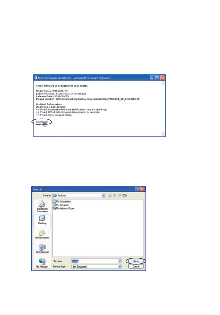
Using the Web-Based Advanced User Interface
7776
Downloading a New Version of Firmware
If you c lick the “C heck Firm wa re ” button an d a new v er sion of
firmware is available, you will see a screen similar to the one below:
1. To download the new version of firmware, click “Download”.
2. A window will open that allows you to select the location where
you want to save the firmware file. Select a location. You can
name the file anyth in g y ou wa nt, or u se the d efault name. Be sure
to locate the file in a place where you can locate it yourself later.
When you have selected the location, click “Save”.
76

Using the Web-Based Advanced User Interface
3. When the save is
complete , y ou wi ll se e
the followi ng wi ndow.
Click “Close”.
The down load of t he
firmware is complete.
To update the firmware,
follow t he next s te ps
in “Upda ting the N1
Vision’s Firmware”.
Updating the N1 Vision’s Firmware
1. In the “ Firmware
Update” page, cli ck
“Browse”. A window will
open that allows you to
select t he locati on of
the firmware update file.
2. Browse to the firmware
file you download ed .
Select the file by
double-c licking o n the
file name.
1
2
3
4
5
section
6
7
8
9
10
7776

Using the Web-Based Advanced User Interface
7978
3. The “Update Firmware”
box will now displa y t he
location an d n am e o f
the firmware file
you just selected.
Click “Update”.
4. You w ill b e a sked if you
are su re you wan t to
continue. Click “OK”.
5. You will see one more message. This message tells you that
the N1 Vi si on may n ot re sp ond f or as lo ng as on e m inute as
the firmware is loaded into the N1 Vision and the N1 Vision is
rebooted. Click “OK”.
6. A 180-seco nd co untdown will appe ar on th e screen. Wh en
the countdown reaches zero, the N1 Vision’s firmware update
will be complete. The N1 Vision’s home page should appear
automa ti cally. If not , typ ei n the N1 Vision’s address(default =
192.168.2.1) into the navigation bar of your browser.
78

Using the Web-Based Advanced User Interface
Changing System Settings
The “System Settings” page is where you can enter a new administrator
password, set the time zone, and enable remote management.
Setting or Changing the Administrator Password
The N1 Visio n ships w it h NO pass wo rd e ntered. If yo u wish to a dd
a passwo rd f or greater se cu rity, y ou can se t a passw ord he re .
Wri te down y our passw ord an d keep it i n a safe place, as y ou will
need it if you ne ed to log i nt o the N 1 Vi si on in the f uture. It is al so
rec ommended that you se t a passw ord if you plan to use t he rem ote
management feature of your N1 Vision.
Changing the Login Time-Out Setting
The logi n time-ou t option al lo ws you to set the pe riod of t im e that yo u
can be l ogged int o the N1 Vision ’s adva nced setu p interface . The tim er
starts w hen there has b een no ac ti vity. For exam pl e, imagin e you hav e
made som e changes i n the adv an ced set up interfac e, then lef t your
computer alone wi th out click in g “Logo ut ”. Assumi ng the time -o ut is
set to 1 0 minutes , 10 minute s after y ou leave, t he login se ss ion wil l
expire. You will h ave to lo g into th e N1 Vision aga in to mak e any more
changes. The logi n time-out op tion is f or securi ty purposes a nd the
default is set to 10 minutes.
Note: Only on e compute r can be lo gg ed into t he N1 Vision’s advan ce d
setup interface at one time.
1
2
3
4
5
section
6
7
8
9
10
7978

Using the Web-Based Advanced User Interface
8180
Setting the Time and Time Zone
The N1 Visio n keeps t im e by c on ne cting t o a Simple Ne twork Tim e
Protocol (SNTP) server. This allows the N1 Vision to synchronize the
system c lock to t he global I nt ern et . The syn ch ro ni zed clock i n the N 1
Vis ion is us ed to record the se curity lo g and control c lient fil te ring.
Select t he time z on e that yo u re si de in. You ha ve the op ti on to sel ec t
a primar y and a b ac kup NTP s er ver to ke ep your N 1 Vi si on’s cl ock
synchronized. Select your desired NPT server from the drop-down
box, or simply ke ep it as is .
If you reside in an area that observes daylight saving, then place a
check ma rk in the b ox next t o “Enable D aylight S av ing”. The s ystem
clock ma y not upd at e immedia te ly. A llow at l ea st 15 min ut es for
the N1 Visio n to cont ac t the tim e servers o n the Int er net a nd get a
response. You cannot set the clock yourself.
Enabling Remote Management
Before you e nable thi s advanced fe ature of your Belkin N 1 Vi si on,
MAKE SURE YOU HAVE SET THE ADMINISTRATOR PASSWORD.
Remote m anagement a llows you t o make ch anges to yo ur N1 Vision’s
settings fro m anywhere on t he Internet. T he re a re t wo method s of
remotely managing the N1 Vision. The first is to allow access to the
N1 Vision from anywhere on the Internet by selecting “Any IP address
can remotely manage t he rou ter”. By ty ping in y our WA N IP address
fro m any com puter on th e Inter net, yo u will be p rese nt ed with a l ogin
screen where you need to ty pe in the p assword of yo ur N1 Vision.
The second method is to allow a specific IP address only to remotely
manage t he N1 Vision. T his is mo re s ec ure, but less convenie nt . To
use this method, enter the IP address you know you will be accessing
the N1 Visio n from in the s pace provided a nd select “Only th is IP
address can remo tely mana ge the N1 Visio n” . Before you enable
this function, it is STRONGLY RECOMMENDED that you set your
administ rator pas sw ord. Leaving th e passw ord em pty will po tentially
open your N1 Vision to intrusion.
80

Using the Web-Based Advanced User Interface
Advanced Feature: The “Remote Access Port” option allows you to
configure th e desired “Re mo te Access P ort for R emote Man ag ement”
. The de fault acc es s port is s et to p or t 80.
feature
Enabling/Disabling UPnP
UPnP (Universal Plug-and-Play) is yet another advanced feature
offered by your Belkin N1 Vision. It is a technology that offers
seamless operatio n of voice me ssaging , video mes sa ging, gam es , and
other ap plication s that are UPnP -c omplian t. Some app li cations requi re
the N1 Visio n’s f irew al l to be c on figured in a specific wa y to oper at e
pro perly. This us ua lly requires open in g TCP and UDP port s, and in
some instances, setting trigger ports. An application that is UPnPcomplian t has the a bility to c ommunic at e with th e N1 Vision, ba si cally
“telling ” the N1 Visi on which wa y it need s the firewall co nfigured. The
N1 Vision ships with the UPnP feature disabled. If you are using any
applicat ions that a re U PnP-compl ia nt, and w ish to ta ke advantag e of
the UPnP features, yo u can enabl e the UPn P feature. Simp ly select
“Enable” in the “ UP nP Enabli ng ” secti on of the “ Ut ilities” pa ge. Click
“Apply Changes” to save the change.
1
2
3
4
5
section
6
7
8
9
10
8180

Using the Web-Based Advanced User Interface
Enabling/Disabling Auto Firmware Update
This inn ovation p rovi de s the N1 Visi on with the built-in c apability
to autom atically ch eck for a n ew vers io n of firm wa re a nd alert yo u
that the new firm wa re i s availab le . When yo u log int o the N1 Vision ’s
advanced interface, the N1 Vision will perform a check to see if new
firmware is available . If so, yo u will be n otified. You ca n choose to
download the new version or ignore it.

Manually Configuring Network Settings
6
5. Close the window.
If you made any changes, the following window will appear.
Click “Save”.
Restar t the co mp uter. When the compu te r resta rt s, your network
settings are now configured for use with the N1 Vision.
Set up the computer that is connected to the cable or DSL modem
FIRST us ing these s teps. You can a lso use t hese step s to add
computer s to your N 1 Vi sion afte r the N1 Vision has been s et up to
connect to the Internet.
Manually Configuring Network Settings in Mac OS up to 9.x
1.
Pull down the Apple menu. Select “Control Panels” and
select“TCP/IP”.
2. Youw ills ee theT CP/IPcontrol panel. Sel ec t“ Ether ne tB uilt-In”
or “Ethernet” in the “Connect via:” drop-down menu (1).
3. Next to “Conf ig ure”
(2), if “Manually” is
selected , y ou r N 1
Vis ion will need to be
set up for a st atic IP
connecti on ty pe. Wri te
the address information
in the table below.
You wi ll ne ed to en ter
this information into
the N1 Vision.
4. If not already set, at “Configure:”, choose “Using DHCP Server”.
This will tell the computer to obtain an IP address from the
N1 Vision.
(1)
(2)
1
2
3
4
5
section
7
8
9
10
8382

Manually Configuring Network Settings
8584
(4)
Manually Configuring Network Settings in Mac OS X
1.
Click on the “System Preferences” icon.
2. Select “Network” (1) from the “System Preferences” menu.
3. Select “Built-in Ethernet” (2) next to “Show” in the
Network menu.
(1)
(2)
(3)
84
(5)

Manually Configuring Network Settings
4. Selectthe“TCP/IP”tab(3). Next to “Configure” (4), yo u sho ul d
see “Manual ly ” o r “ Us ing DHCP”. If you do not, check the
PPPoE tab (5) to make sure th at “Connect using PP Po E” is NO T
selected. If it is, you will need to configure your N1 Vision for a
PPPoE connection type using your user name and password.
5. If “Manually” is selected, your N1 Vision will need to be set up
for a static IP connection type. Write the address information
in the table below. You will need to enter this information into
the N1 Vision.
6. If not already selected, select “Using DHCP” next to “Configure”
(4), then click “Apply Now”.
Your network settings are now configured for use with the
N1 Vision.
1
2
3
4
5
6
section
7
8
9
10
8584

Manually Configuring Network Settings
8786
(2)
(3)
5. If “Use the following IP address” (2) is select ed , y ou r N 1 Visio n
will need to be set up for a static IP connect io n t yp e. Writ e t he
address information the table below. You will need to enter this
information into the N1 Vision.
6. If not already selected, select “Obtain an IP address
automatically” (1) and “Ob ta in DN S s erver address automat ic ally”
(3). Click “OK”.
Your network settings are now configured for use with the
N1 Vision.
Manually Configuring Network Settings in Windows 2000, NT®, or XP
1.
Click “Start”, “Settings”, then “Control Panel”.
2. Double-click on the “Network and dial-up connections” icon
(Windows 2000) or the “Network” icon (Windows XP).
3. Right-click on the “Local Area Connection” associated with
your network adapter and select “Properties” from the
drop-down menu.
4. In the “Local Area Connect io n P rope rt ies” window, click “Int ernet
Protocol(TCP/IP)”andclickthe“Properties”button.The
following screen will appear:
(1)
86

Manually Configuring Network Settings
(3)
3. If “Specif y a n IP add ress ” is sel ec ted, your N1 Vi si on will need to
be set up for a st atic IP connectio n t yp e. Writ e the ad dres s
information in the table below. You will need to enter this
information into the N1 Vision.
4. Write the IP address and subnet mask from the “IP Address”
tab (3).
5. Click the “Gateway” tab (2). Write the gatewa y add ress do wn in
the chart.
6. Click the “DNS Configuration” tab (1). Wr ite t he DNS a ddre ss(es)
in the chart.
7. If not already selecte d,
select “Obtain IP
address automat ic ally”
on the IP address t ab.
Click “OK”.
Restar t the co mp uter. When the compu te r resta rt s, your network
adapter(s) are now configured for use with the N1 Vision.
Manually Configuring Network Adapters in Windows 98SE or Me
1.
Right -c lick on “My N etwork Neigh bo rhood” and select
“Properties” from the drop-down menu.
2. Selec t “TC P/ IP Settings” for you r ins talled network ad ap ter. You
will see the following window.
(1)
(2)
1
2
3
4
5
6
section
7
8
9
10
8786

Recommended Web Browser Settings
8988
In most cases, yo u will not ne ed to m ak e any cha ng es to you r web
bro wser’s setting s. If you a re h av ing trouble a ccessing th e Inter net or
the adva nced web- ba sed user in terface , then chan ge your browser ’s
settings to the recommended settings in this section.
Microsoft® Internet Explorer 4.0 or Higher
1.
Start your web browser. Select “Tools” then “Internet Options”.
2. In the “Inter net Options” sc reen , the re are thre e s elections :
“Never dial a connection”, “Dial whenever a network connection
is not present”, and “Always dial my default connection”. If you
can make a selection, select “Never dial a connection”. If you
cannot make a selection, go to the next step.
3. Under the “Internet Options” screen, click on “Connections” and
select “LAN Settings…”.
88

Recommended Web Browser Settings
1
9
2
3
4
5
6
7
8
10
4. Make sure there are no check marks next to any of the displayed
options: “A ut omaticall y d et ect settings ”, “U se au tomatic
configuration script”, and “Use a proxy server”. Click “OK”. Then
click “OK” again in the “Internet Options” page.
Netscape® Navigator® 4.0 or Higher
1.
Start Netscape. Click on “Edit” then “Preferences”.
2. In the “Preferences” window, click on “Advanced” then select
“Proxies”. In the “Proxies” wind ow, se lect “Direct connecti on
to the Internet”.
section
8988

Troubleshooting
9190
Assistant CD does not automatically start.
If the CD-ROM does not star t t he As si stant softwa re automa tically,
it could be that the computer is running other applications that are
interfer ing w ith the CD drive.
1. If the Assistant software’s Welcome screen does not appear
within 15-2 0 s ec onds, open up your CD-ROM driv e b y
double-c licking on the “My Comput er ” i con t hat is l ocated on
your desktop.
2. Next, double-click on the CD-ROM drive that the Assistant
software CD has been placed in to start the installation.
3. The Assist an t s oftware s hould start withi n a few sec on ds. If,
instead, a window appears showing the files on the CD,
double-click on the icon labeled “setup.exe”.
4. If the Assista nt so ft ware st ill d oes not start, reference the section
titled “Manually Configuring Network Settings” (page 83) in this
User Manual for an alternative setup method).
Assistant software cannot find my N1 Vision.
If the Assista nt so ft ware is no t a bl e t o f in d t he N1 Vision du ri ng th e
installation process, please check the following items:
1. I f t he As sistant soft wa re is not able to find the N1 Vision during
the installation process, there may be third-party firewall
software installed on the computer attempting to access the
Internet. Examples of third-pa rty f irew all software are Zo neAlarm,
BlackICE PC Protecti on, M cAfee Person al Fi rewa ll, a nd Norton
Personal Firewall. If you do have firewall software installed on
your comput er, p lease make sure t hat you prop erly configu re it.
You ca n d et ermine if the firewall softwa re is preventing In te rnet
access by temp or arily turn ing i t o ff. If, whil e t he fi rewa ll is
disabled , I nt ernet ac ce ss works pro perly, y ou wi ll ne ed to ch ange
the firewall settings to function properly when it is turned on.
Please refer to the instructions provided by the publisher of your
firewall softwa re for instr uc tions on configur ing t he fire wall to
allow Internet access.
90

Troubleshooting
1
9
2
3
4
5
6
7
8
10
2. Unplug power to the N1 Vision for 10 seconds, and then plug the
power back into the N1 Vision. Ensure that the N1 Vision’s “router”
icon is on. If not, check to make sure that the AC adapter is
connected to the N1 Vision and plugged into a wall outlet.
3. Ensure that you have a cable connected between (1) the netw or k
(Ethernet) port on the back of the computer and (2) one of the “to
Wired Computers” ports on the back of the N1 Vision.
Note: The c omputer shou ld NO T b e con ne cted to the port labele d
“to Modem” on the back of the N1 Vision.
4. Try shutti ng do wn an d resta rting your comput er, t hen rer un ning
the Assistant software.
If the Assistant software is still unable to find the N1 Vision, reference
the section titled “Manually Configuring Network Settings” for
installation steps.
Assistant software cannot connect my N1 Vision to the Internet
If the Assista nt so ft ware is no t a bl e t o c on nect the N1 Vis io n t o t he
Internet, please check the following items:
1. Use the troubleshooting suggestions within the Assistant
software.
2. If your ISP requires a user name and password, make sure
that you have typed in your us er na me an d p as sword c orre ctly.
Some user names require that the ISP’s domain may be at the
end of the name. Example: “myname@myisp.com”. The “@myisp.
com” part of the user name may need to be typed as well as your
user name.
If you continu e to hav e no Int er net connec tion, ref eren ce the s ection
titled “Manually Configuring Network Settings” (page 83 of this User
Manual for an alternative setup method).
section
9190

Troubleshooting
9392
• The Assistant software completed installation, but my web
browser doesn’t work.
• I am unable to connect to the Internet. The “modem” icon on
my N1 Vision is blinking, and the “internet” icon is blinking.
If you cannot connect to the Internet, and the “modem” icon is
blinking , a nd th e “ in terne t” ic on is bl inking, the problem may be that
your modem and N1 Vision are not connected properly.
1. Make sure the network cab le be tw een the modem and the N1
Vis ion is c onnected. Th e cab le sh ould be connected at one end
to the N1 Vi si on’s “to Mode m” po rt, a nd at th e o ther end to t he
network port on your modem.
2. Unplug the cable or DSL modem from its power source for
three minutes. After th ree minut es, p lug the modem back into its
power source. This may force the modem to properly recogniz e
the N1 Vision.
3. Unplu g the po we r t o y ou r N 1 Visio n, wa it 10 se co nds, and then
rec onnect the power. Th is wi ll ca use the N1 Visi on to reatte mpt
communic ation with the modem. If the “mod em ” i con o n t he
N1 Vis ion i s n ot li t a fter complet in g t he se steps, please con ta ct
Belkin Technical Support.
4. Try shutting down and restarting your computer.
92

Troubleshooting
1
9
2
3
4
5
6
7
8
10
• The Assistant software completed installation, but my web
browser doesn’t work.
• I am unable to connect to the Internet. The “modem” icon on
my N1 Vision is on, and the “internet” icon is blinking.
1.
If you cannot conn ec t t o t he In terne t, th e “ mo dem” icon is on,
and the “internet” icon is blinking, the problem may be that your
connection type may not match the ISP’s connection.
2. If you have a “static IP address” conn ec tion, your ISP must
assign you the IP address, subn et ma sk, a nd gateway address.
Please refer to the section entitled “Alternate Setup Method” for
details on changing this setting.
3. If you have a “PPPoE” connection, your ISP will assign you a user
name and password and s om et im es a serv ic e name. Make sure
the N1 Vis io n’s c on nection type is configure d to PPPoE and the
settings are e nt ered p roperly. Please refer to the section entitled
“Alternate Setup Method” for details on changing this setting.
4. You m ay ne ed to co nfigure your N1 Vis ion t o m eet t he specific
requirements of your ISP. To search our knowledge base for
ISP-sp ec ific issues,goto: http: // web.belki n. com/sup po rt an d
type in “ISP” into the “Product Support Search” text box.
If you are s ti ll un able to access the Inte rnet after veri fy ing these
settings, please contact Belkin Technical Support.
section
9392

Troubleshooting
9594
• The Assistant software completed, but my web browser
doesn’t work.
• I am unable to connect to the Internet. The “modem” icon on
my N1 Vision is blinking, and the “internet” icon is solid.
1.
If the “modem ” ico n i s bli nk ing, and the “internet” icon is
solid, but you are unable to access the Internet, there may be
third-party firewall software installed on the computer attempting
to access the Inter net. Examp le s o f t hi rd -p arty firewall software
are ZoneAlarm, BlackICE PC Protection, McAfee Personal
Firewall, and Norton Personal Firewall.
2. If you do have firewall software installed on your computer,
please make su re that you properly con fi gure it . You can
determine if the firewall software is preventing Internet access by
temporar ily t urnin g i t off. If, while the firewall is disa bled, Intern et
access works properly, you will need to change the firewall
settings to function properly when it is turned on.
3. Please refer to the instruct io ns provided by the p ublisher of y ou r
firewall software for in st ru ct io ns on c on fi gu ri ng the fi rewall to
allow Internet access.
If you are s ti ll un able to access the Inte rnet after disa bl ing any fire wall
software, please contact Belkin Technical Support.
94

Troubleshooting
1
9
2
3
4
5
6
7
8
10
I can’t connect to the Internet wirelessly.
If you are u na ble t o c onnect to the Internet from a wireles s c om puter,
please check the following items:
1. Look at the lights on your N1 Vision. They should be as follows:
•The“router”iconshouldbeon.
•
The“radiowave”iconabovethe“router”iconshouldbeon.
•The“modem”lightshouldbeon,andnotblinking.
•The“internet”iconshouldbeon,andnotblinking.
•The“Wireless”lightshouldbeon,notblinking.
2. O pen y our wireless utilit y sof tw are b y cli ck ing on t he icon in the
system tray at the bottom, right-hand corner of the screen.
3. T he ex act window that open s w il l v ar y d epending on the mode l of
wireless card you have; however, any of the utilities should have
a list of “Ava ilable Netwo rk s”—those wireless net wo rks it c an
connect to.
Doesthe name of your wireless net wo rk ap pear in theres ults?
Yes, m y n et work name is listed— go to th e trouble shooting solut io n
titled “I can’t connect to the Int er net wirelessly, but my network name
is listed”.
No, my network name is not listed—go to the troubleshooting solution
titled “I can’t connect to the Int er net wirelessly, and my network name
is not listed”.
section
9594

Troubleshooting
9796
I can’t connect to the Internet wirelessly, but my network name
is listed.
If the name of your network is list ed in th e “ Avai la ble N etworks” lis t,
please follow the steps below to connect wirelessly:
1. Click on the correct network name in the “Available
Networks” list.
2. If the network has security (encryption) enabled, you will
need to enter the netw or k k ey. For more informati on regarding
security, see the section entitled “Changing the Wireless
Security Settings”.
3. W ithin a few s econds, the tra y ico n i n the lo we r, le ft-hand corner
of your screen should turn gree n, in dication of a successf ul
connection to the network.
I can’t connect to the Internet wirelessly, and my network name
is not listed.
If the correct network nam e is not list ed un der “ Av ai lable Networ ks ” i n
the wireless utility, please attempt the following troubleshooting steps:
1. Tempo rarily move compu te r, if po ssible, five to 10 feet from the
N1 Vis ion. Close the wireless utili ty, and re open it. If t he correct
network name now appears under “Available Networks”, you may
have a range or interf eren ce proble m. Pl ease see the suggestio ns
discussed in the section titled “Placement of your N1 Vision” in
this User Manual.
2. U sing a c omputer that is conn ec ted t o t he N1 Visi on vi a a
network cab le (a s o pp osed to wire lessly), ens ure that “Broadc as t
SSID” is enabled . Thi s s et ting is fo und on t he N1 Vision ’s wireless
“Channel and SSID” configuration page.
If you are s ti ll un able to access the Inte rnet after comp le ting these
steps, please contact Belkin Technical Support.
96
 Loading...