

Page 1
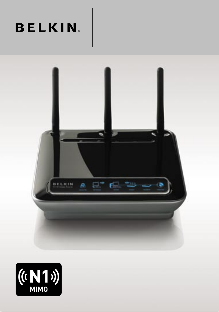
N1 Wireless
Router
User Manual
F5D8231-4
Page 2

Table of Contents
1. Introduction . . . . . . . . . . . . . . . . . . . . . . . . . . . . . . . . . . . . . . 1
Advantages of a Wireless Network . . . . . . . . . . . . . . . . . . . . 1
Placement of your N1 Wireless Router . . . . . . . . . . . . . . . . . 3
2. Product Overview . . . . . . . . . . . . . . . . . . . . . . . . . . . . . . . . . . 7
Product Features . . . . . . . . . . . . . . . . . . . . . . . . . . . . . . . . . 7
3. Knowing your Router . . . . . . . . . . . . . . . . . . . . . . . . . . . . . . 10
Package Contents . . . . . . . . . . . . . . . . . . . . . . . . . . . . . . . 10
System Requirements . . . . . . . . . . . . . . . . . . . . . . . . . . . . . 10
Setup Assistant Software System Requirements . . . . . . . . 10
4. Connecting and Configuring your Router . . . . . . . . . . . . . . . 15
5. Alternate Setup Method . . . . . . . . . . . . . . . . . . . . . . . . . . . . 23
6. Using the Web-Based Advanced User Interface . . . . . . . . . . 38
Changing LAN Settings. . . . . . . . . . . . . . . . . . . . . . . . . . . . 39
Viewing the DHCP Client List Page. . . . . . . . . . . . . . . . . . 41
Configuring the Wireless Network Settings . . . . . . . . . . . . 41
Setting WPA Security . . . . . . . . . . . . . . . . . . . . . . . . . . . . . 48
Setting WEP Encryption . . . . . . . . . . . . . . . . . . . . . . . . . . . 50
Using the Access Point Mode. . . . . . . . . . . . . . . . . . . . . . . 52
Setting MAC Address Control . . . . . . . . . . . . . . . . . . . . . . 53
Configuring the Firewall . . . . . . . . . . . . . . . . . . . . . . . . . . . 55
Using Dynamic DNS . . . . . . . . . . . . . . . . . . . . . . . . . . . . . 59
Utilities . . . . . . . . . . . . . . . . . . . . . . . . . . . . . . . . . . . . . . . 60
Restarting the Router . . . . . . . . . . . . . . . . . . . . . . . . . . . . 61
Updating the Firmware . . . . . . . . . . . . . . . . . . . . . . . . . . . 66
7. Manually Configuring Network Settings. . . . . . . . . . . . . . . . 74
8. Recommended Web Browser Settings . . . . . . . . . . . . . . . . . 79
9. Troubleshooting . . . . . . . . . . . . . . . . . . . . . . . . . . . . . . . . . . 81
10. Information . . . . . . . . . . . . . . . . . . . . . . . . . . . . . . . . . . . . 97
Page 3

Introduction
2
Thank you for purchasing the Belkin N1 Wireless Router (the Router).
Following are two short sections—the first discusses the benefits of home
networking, and the other outlines best practices that maximize your
wireless home network range and performance. Please be sure to read
through this User Manual completely, and pay special attention to the
section entitled “Placement of your Wireless Networking Hardware for
Optimal Performance” on the next page. By following our simple setup
instructions you will be able to use your Belkin Home Network to:
• Share one high- speed Internet c onnection with all the computer s in
your home
• Share resource s, s uc h as files and hard dr iv es a mong a ll t he
connect ed com puters in yo ur h om e
• Share a single printe r wi th the entire family
• Share doc um ents, music, video, and digital pictu res
• Store , retrieve, and copy files from one compu ter to ano th er
• Simulta ne ously play games online, check Internet email , and chat
Advanta ge s of a Wirel ess Ne twork
Here are so me of the advant ag es o f sett ing up a Belkin
Wirel ess Ne twork:
• Mobilit y – you’ll no longer need a dedicated “com pu ter
roo m” —now y ou c an wor k on a networked lap to p or deskt op
compute r anyw here within your wire less r ange
• Easy instal la tion – Bel kin’s Easy Install ation Wizard make s
setup simple
• Flexibi lity – set up and access printer s, com puters, and other
network in g de vices from anywhe re i n yo ur hom e
• Easy expans io n – the wide range of Belkin network in g products let
you expand your network to include device s su ch as printe rs a nd
gaming consol es
• No cabling re qu ired – y ou c an spa re the e xpense and hassle of
ret rofitti ng Eth er ne t cabl ing th roughou t th e home or offi ce
• Widespread industry acce pt ance – cho ose from a w id e ra nge of
interoperable networ ki ng p roducts
1
Page 4

2
Introduction
Revolut io nary N 1 Wi reless Tech no logy w ith MI MO ( N1 M IM O)
Your Belkin N1 Wire le ss R ou ter uses a new smart -a ntenna technolo gy
called Multip le Inp ut M ul tiple Output (MIMO). N1 MIMO complies
with the IEEE draft 802.11n specifi cation. It i ncrea se s sp ee d, r ange,
rel ia bility, and spec tr al e fficien cy for wireless networkin g sy st ems.
The element that makes Belkin ’s N1 M IM O te chnology diff erent
fro m a conventi onal r adio i s th e use of multipl e ante nnas a nd t wo
simulta ne ous data s treams to deliver wireless transfers around your
home or office. A convent io nal ra dio uses o ne a nt enna to tr ansmit
a da ta s tream. Belkin ’s N1 M IMO, o n th e othe r hand , us es three
antenna s. Thi s desi gn h el ps c om bat distortion and interf erence.
Belkin’s N 1 MI MO is multid imensional. It builds on one-dime nsional
smart-a nt enna technology by simult an eously transmit ting t wo d at a
strea ms t hrough the same channel , whic h increases wirel ess capacity.
section
1
2
3
4
5
6
Another eleme nt tha t en ha nces B elkin’s N1 MIMO is the use of
aggre gation as specified in the d raft 802.11n specif ic ation. By
shorten in g th e spac e be tw een pa ckets and combining multi pl e sm aller
packets into one larger p acket, Belkin’s N1 MIM O can transm it m ore
data thro ug h av ailable bandwid th .
Think of convention al r ad io t ra nsmission as a t wo-lane highway. T he
speed limit governs the maximum allowab le f lo w of traffic throug h
that lane. Compared w ith co nventiona l radi os, on e-dimension al s ma rt
antenna syste ms hel p mo ve tra ffic thro ug h th at lan e fa st er a nd more
rel ia bly—analo go us t o a four-la ne road on w hi ch t ra ffic consis te ntly
moves at a r at e cl os er t o the spee d limi t. Bel kin’s N1 MIMO helps
traff ic m ov e at the speed limit and opens more la ne s—to become the
superhi gh way in thi s ex am ple. T he r ate of tra ffic flow is m ultiplied by
the number of lanes that are opened.
2
7
8
9
10
Page 5

Introduction
43
Placement of your N1 Wireless Router
Important Factors for Placement and Setup
Your wire le ss c onnection will be stron ge r th e clos er y ou r co mp uter is
to y our Router. Typical indoor operat in g ra ng e fo r wireless devices is
between 100 and 200 feet.
In t he s ame wa y, your wirele ss c on nection and performan ce w il l
degrade somew hat as the dista nc e be tween your R outer and
connect ed dev ices i ncrease s. T hi s ma y or may not be n oticeable
to y ou. As y ou mov e furt her from your Router, connection spee d
may decre as e. F actors that can we aken signals simply by getting
in t he w ay o f your netwo rk’s radio waves are metal app li ances or
obstruc ti ons, and w alls.
If y ou h ave co ncer ns a bout y our ne twork’s perf ormance that might
be relate d to range or obstruct io n fa ctors, try m oving the computer
to a pos ition between five and 10 fe et f rom the Router in order to s ee
if d istance is the p roble m. If diff iculties persis t ev en at close range,
please contac t Belk in Tec hnical Support.
Note: While some of the items listed below can affect netwo rk
perform an ce, they w ill no t prohibit your wireless network fro m
functio ni ng; if you are c on cern ed t hat yo ur n et work i s no t op er ating at
its maximum eff ectiveness, thi s chec kl ist may he lp.
1. Router Placement
Place your Router, the central connecti on p oi nt o f your
network , as close as possible to the center of your wireles s
network devic es.
To achieve the best wirel es s ne twork coverage for your “wire le ss
clients ” (i.e ., com puters enabled by Belkin Wire less N otebook
Network Cards, Wireles s Desk top Ne twork Cards , and Wire less
USB Adapters) :
• Ensure th at y ou r Ro ut er’s netwo rk ing an tennas are parall el
to e ach other, a nd are p ositioned vertica lly (t oward the
ceiling ). If your Route r itse lf is positi oned v ertically, p oint t he
antenna s as much as possible in an u pward direction.
• In multisto ry hom es , pl ace th e Ro ut er o n a floor that is as
close to the c enter of t he hom e as possi bl e. T his ma y me an
placing the Router on an upper floor.
• Try no t to place the Route r near a cordl ess 2. 4GHz p hone.
Page 6

4
Introduction
2. Avoid Obstacles and Interference
Avo id pla ci ng y our Ro uter n ear de vices that may e mit radio
“noise, ” such as microwave ovens. Dense objects that can inhibit
wirel ess co mmunicati on inc lude:
• R efrigerat or s
• Wa sh ers an d/or dryers
• M etal cabinets
• L arg e aqua ri ums
• M etallic-b as ed, UV-tinted window s
If y our wireles s sign al s ee ms w ea k in som e spot s, mak e sure t hat
objects such as these are not blockin g th e sign al ’s path (between
your computer s and Rout er ).
3. Cordless Phones
If t he p erformance of your wire le ss n etwork is im paire d afte r
attendi ng to the above issues , and you have a cordles s phon e:
• Try movin g co rdless phones away from you r Ro ut er a nd you r
wirel ess-enabl ed com pu ters.
• U nplug and remove the batter y from a ny cordless phone
that operates on the 2.4GHz band (check manuf ac turer ’s
informa ti on). If th is f ix es t he problem, your phone may
be i nterferin g.
• I f yo ur pho ne s up ports channel selecti on, ch ange t he c hannel
on t he p hone t o th e fart hest c hannel from your wire less
network . For exampl e, c ha nge th e ph one to cha nn el 1 and
move your Router to channel 11. See your p hone’s use r
manual for detailed ins tr uctions.
• I f ne cessary, con si der switching to a 9 00 MHz or 5 GH z
cordl ess ph one.
section
1
2
3
4
5
6
7
8
9
10
4. Choose the “Quietest” Channel for your Wireless Network
In location s where ho mes or offices are clos e toge th er, such as
apartme nt bui ldings or office comple xe s, t here may be wi reles s
network s near by tha t ca n conf li ct w ith yo urs.
Use the Site S urvey capabilit ies fo und in the Wireless Utility of
your wire le ss a dapter to lo cate a ny o ther w ireless net wo rks th at
are avail ab le ( see yo ur w ireless adapt er ’s user manual), and move
your Router and compute rs to a channel as far away f rom other
network s as possibl e.
4
Page 7

Introduction
65
• Expe riment with more than one of the avai lable channel s, in
order to find the cl earest c onnection and avoid interference
from neighb oring cordless phones or oth er wirel ess devices.
• For Belkin wireless networking p roduct s, use the detailed Si te
Sur vey and wireless channel inf ormation incl uded with your
wireless ne twork card. See your network c ard’s user g uide for
more inform ation.
These guid el ines s hould allow you to c ov er t he max imum
possibl e area w ith yo ur R ou ter. Sho uld yo u ne ed to cover an
even wider area , we sugge st the Belki n Wi reless Range
Extende r/ Access Point.
5. Secure Connections, VPNs, and AOL
Secure co nn ections typical ly require a user name and
password, a nd a re used where secur it y is impor tant. Secure
connect io ns i nclude:
• Virtua l Priv ate Ne twork (VPN) connectio ns , of ten us ed t o
connect rem otely to a n office network
• T he “ Bring Your O wn A ccess” progra m from A merica Online
(AOL), which lets you use AOL through broadband prov ided b y
another cable or DSL service
• M ost online banking websit es
• M any commerc ial we bsites that requi re a use r name and
password to acc ess yo ur a cc ount
Secure co nn ections can be i nterrupte d by a computer’s
power managem ent se tting, which causes it to “g o to sleep .”
The simplest soluti on t o avoi d this is to simply reco nnect by
rer un ning t he V PN or AOL softwa re, or b y re-logging into the
secure we bs ite.
A se cond alternative is to c hange your c omputer’s po wer
managem en t se ttings so it doe s not go to s leep; however, this
may not be a pp ropriat e fo r port ab le c omputers. To change your
power managem ent se tting under Windows, see the “Power
Options ” item in the Contro l Pa ne l.
If y ou c ontinue to h ave difficu lt y wi th S ec ure Connect io ns, VP Ns,
and AOL, please revie w th e step s abov e to be sure you have
addre ssed t hese issues.
Page 8

6
Introduction
For more information regarding our networking products, visit our website
at www.be lk in.com/ne tworking or call Belkin Technical Support at:
US: 877-736-5771
310-898-1100 ext. 2263
Europe: 00 800 223 55 460
Australia: 1800 235 546
New Zealand: 0800 235 546
Singapore: 800 616 1790
section
1
2
3
4
5
6
7
8
9
10
6
Page 9

Product Overview
87
Product Features
In m inutes you will be a ble to sha re y our In ternet c onnection and
network your comput ers. T he f ol lowing is a li st of features that make
your new Belkin N1 W irele ss Rou te r an ide al sol ut ion for yo ur h om e or
small off ic e ne twork.
Works with Both PCs and Mac® Computers
The Router supports a variety of networki ng e nv ironm en ts i nc luding
Mac OS® 8 .x , 9. x, X v10.x , Linu x®, Wi ndows® 9 8, Me, NT®, 20 00,
and XP, and others. All that is n eeded is a n Inte rn et browser and a
network adapt er tha t su pp orts T CP/IP (the standard l an guage of
the Internet).
Patent-Pending Network Status Display
Lighted LEDs on the front of the Router indicat e whic h func tions
are in operatio n. You ’l l kn ow at- a-glance whethe r your Route r is
connect ed to the Internet. This feature e liminates the need for
advance d soft ware and status-m on itoring pro ce dures .
Web-Based Advanced User Interface
You can set up the Route r’s advanced funct ions e asily throu gh you r
web brows er, withou t ha vi ng t o inst all ad ditional softwa re o nto the
compute r. There are n o di sk s to insta ll or keep track of and, best
of a ll, you ca n ma ke cha nges a nd p er form s etup functions from a ny
compute r on the network quick ly and easil y.
NAT IP Address Sharing
Your Router employs Net wo rk A dd ress Translatio n (N AT) to share the
single IP addre ss ass igned to y ou by your Inter net Servic e Provider
while saving the cost of adding additiona l IP addresses to your
Internet service acco un t.
SPI Firewall
Your Router is equipped with a firewa ll t ha t wi ll protect your network
fro m a wide array of c ommon hacker attack s incl ud ing IP Spo ofing,
Land Attack, Ping of Death (PoD), Denial of Service (DoS) , IP with
zero leng th , Sm urf At tack, TCP Nu ll S can, S YN f lo od, UDP fl ooding,
Tear Drop Attac k, I CM P de fe ct, RIP de fect, and fr agment flooding .
Page 10

8
Product Overview
Integrated 10/100 4-Port Switch
The Router has a b ui lt-in, four-po rt net wo rk s witch to a ll ow y our
wired com pu ters to sh are printer s, dat a and MP3 files, digit al pho tos,
and much more. The switch featu res automatic detec tion s o it will
adjust to the speed of c onnected devices. The switc h will tra ns fer
data between comput ers an d th e Inte rnet sim ul taneously witho ut
interru pt ing or con suming reso urces.
Universal Plug and Play (UPnP)
UPnP is a te ch nology that offer s seam less o peration of voice
messagi ng , vi deo me ssaging, games, and other appli ca tions that
are UPnP- co mpliant.
Support for VPN Pass-Through
If y ou c onnect to yo ur o ffice network from ho me u si ng a VPN
connect io n, y our Ro uter w ill al low your V PN-equipp ed com pu ter to
pass thro ug h th e Rout er a nd to your off ice ne twork.
Built-In Dynamic Host Configuration Protocol (DHCP)
Built-I n Dyna mic Ho st C on figuratio n Protocol (DHCP) on-board makes
for the easiest possibl e conn ec tion of a netw or k. T he DHC P se rv er
will assign IP addres ses to eac h comp uter a utomatica ll y so there i s
no n eed for a comp li cated networkin g setu p.
Setup Assistant
The Setup Assistant , se co nd g en eration of Belkin’s renowned Easy
Install Wizard, takes the g uesswork out of setting up your Router.
This automati c soft ware determ in es y ou r ne twork settings for you
and sets up th e Ro ut er f or con nection to y our Internet S ervice
Pro vi der (I SP). In a matt er of minute s, y ou r Ro ut er w ill be up and
running on the Internet.
1
section
2
3
4
5
6
7
8
9
10
Note: Setup Assist an t so ftware is compati bl e wi th Win dows 2 000 an d
XP. If you are using another opera ting s ystem, the R outer can be s et
up u sing the A lter nate Setup Method describ ed in this User Manual
(see page 23).
8
Page 11

Product Overview
Integrated N1 Wireless Access Point
N1 M IMO is a n exci ti ng n ew wireless techn ol ogy ba sed on the dra ft
IEEE 802.11n specif ication. It employs MIMO (Multi pl e In pu t Mu ltiple
Output) smart -antenna techno lo gy t ha t ac hieves data rates of u p to
300Mbps .* Act ual th roughpu t is typic al ly l ower t han th e co nn ected
data rate and will v ary depending on your networkin g envi ronment .
*NOTE: The standard t ransmissi on rat e— 300Mbps—i s the physic al
data rate. Actual data thro ughput will be l ower.
MAC Address Filtering
For added security, yo u ca n se t up a list o f MA C addresses (unique
client identi fiers) that are allowed acces s to your networ k. Eve ry
compute r has its own MAC addres s. Sim ply en ter th ese MAC
addre sses i nto a list usi ng the Web- Ba sed Advanced User Interfa ce
and you can co ntrol acces s to your networ k.
Page 12

Knowing your Router
Package Contents
• Belkin N1 Wirel ess Ro uter
• Quick Install ation Guide
• Belkin Setup Assist ant So ftware CD
• RJ45 Ethernet Network in g Ca bl e
• Power Supply
• User Manual
• Network Statu s Disp lay Gu ide
• Wirel ess Se curity Setup Guide
System Requirements
• Bro ad band I nternet connectio n such as a c able o r DS L mode m
with RJ45 (Ethernet) connec ti on
• At l east one c omputer with an installed netwo rk int er face adapter
• TCP/IP networ king p rotocol ins ta lled o n ea ch com puter
• RJ45 Ethernet network in g ca bl e
• Internet brow ser
Setup Assistant Software System Requirements
• A PC run ning W indows® 2 00 0 or XP
• Minimum 500MH z processor and 128MB RAM
• Internet brow ser
1
2
section
3
4
5
6
7
8
9
10
10
Page 13
Knowing your Router
1211
The Router has been designed to be p laced on a deskt op. Al l of the
cables exit fro m the re ar o f the Router for bette r organizat io n an d
utility. T he N et work S tatus Display is easily visible on the FRONT
of t he R outer to p rovide you with informa ti on a bo ut n etwork activity
and status. See the Network Status Displa y Gu id e fo r more
detaile d info rmation.
(A) (B) (C) (D/E) (F) (G)
A. Wireless Security
OFF Wirel ess se curity is off
Solid Blue Wirel ess se curity is on
B. Wireless-Computer Status
OFF Wirel ess co mputer is not present
Solid Blue Wirel ess co mputer is connected to
the Router
Blinkin g Ambe r Pro bl em w it h wi reless comput er
connect in g properly to the Router
C. Wired-Computer Status
OFF Wired com pu ter is not present
Solid Blue Wired com pu ter is con nected to
the Router
Blinkin g Ambe r Pro bl em w it h wi red computer conn ec ting
pro pe rly to the Route r
Page 14
12
Knowing your Router
D. Router/Power Status
When you apply power to the Router or restart it, a short period of
time elapses while the Router boots up. During this time, the “router”
icon blinks. When the Router has completely booted up, the “router”
icon becomes a solid light, indicating the Router is ready for use.
OFF Router is off
Blinkin g Blue Router is booting up
Solid Blue Router is on a nd ready
1
2
section
3
4
5
E. Wireless Status
OFF Wirel ess is off
Solid Blue Wirel ess is on
F. Modem Status
This icon lights in blue to in dicate that your modem is co nnected
pro pe rly to the Route r. It turns a mber w hen problem is detect ed .
OFF Router is NOT connected to modem
Solid Blue Router is connected to modem and
Blinkin g Ambe r Pro bl em w it h mo dem
G. Internet Status
Thi s unique icon shows yo u when the Router is connected to the
Int ernet. When the light is off, the Router is NOT connected to the
Int ernet. When the light is blinking amber, the Router is attemp ting
to co nnect to the Internet. When the li ght is solid blue, the R outer
is co nnected to the Inter net. When us ing the “Disconnect after x
min utes” feature, this icon bec omes extremely useful in mon itoring
the s tatus of your Router ’s connection.
OFF Router is NOT connected to the Internet
Blinkin g Ambe r Router is attemptin g to conne ct to
Solid Blue Router is connected to the Internet
functio ni ng p roperly
the Internet
6
7
8
9
10
12
Page 15
Knowing your Router
1413
(K)(I)(H) (J)
H. Connections to Wired Computers
Connect your wired (n on-wire less) computers to these ports.
These ports are RJ45, 10/ 10 0 au to -negotiat ion, a uto-uplinki ng
ports for standard UT P ca te gory 5 or 6 Ethernet cable. The ports
are label ed 1 through 4 , wi th onb oa rd LEDs on t he c on nectors.
I. Connection to Modem
This port is f or c on nection to your cable or D SL mod em. Us e th e
cable that was provid ed w it h th e mode m to conne ct the modem
to t his port. Use of a cable other than the one supplied with the
cable modem may not work proper ly.
- Yellow
- Gray
Page 16

14
Knowing your Router
J. Reset Button
The “Reset” button is used in rare cases when the Router may
functio n improperly. Re setting the Router will res to re the R outer’s
normal operat ion wh ile ma intaining the pro grammed settings. You
can also restore the fa ctory default setting s by using the “Reset”
button. Use the resto re option in i nstances where yo u ma y have
forgotten your custom passwo rd.
i. Resetting the Router
Push and releas e the “Res et ” bu tt on. The li ghts o n th e
Router will momenta rily f lash. The “Power/Read y” l ig ht w il l
begin to blink. When the “Power/Rea dy” li ght be comes solid
again, the rese t is compl et e.
ii. Restoring the Factory Defaults
Pre ss and hold the “Reset ” butt on for at least 10 seconds,
then rele as e it . The ligh ts on the Router will moment arily
flash. The “Power/R eady” light will begin to bl ink. W hen
the “Power/Re ady” l ight b ecomes solid again, the res to re
is c omplete.
K. Power Jack – Black
Connect the include d 12 V/ 1A D C powe r supp ly t o this jack.
1
2
section
3
4
5
6
7
8
9
10
14
Page 17
Connecting and Configuring your Router
1615
Verify the contents of your box. You should have the following:
• Belkin N1 Wirel ess Ro uter
• RJ45 Ethernet Network in g Ca bl e
• Power Supply
• Belkin Setup Assist ant So ftware CD
• User Manual
• Network Statu s Disp lay Gu ide
• Wirel ess Se curity Setup Guide
Modem Requirements
Your cable or DSL mo dem must b e eq ui pped w ith an R J4 5 Et he rn et
port. Many modems have both an RJ45 Ethernet port and a USB
connect io n. I f you have a modem with both Ethernet and U SB, an d
are using the USB connect io n at this time , you will be instruct ed to
use the RJ45 E ther net port d uring the in stallatio n procedure . If your
modem has only a U SB por t, you can req uest a differen t ty pe of
modem fro m your ISP, or you can, in s ome cases, purcha se a modem
that has an RJ 45 E th er net po rt o n it.
Ethernet USB
Setup Assistant
Belkin has prov ided o ur S et up A ss istant software t o ma ke ins ta lling
your Router a simple and easy task. You ca n us e it to get your Router
up a nd r unning in mi nutes. The Setup Assistan t re quire s that your
Windows 2000 or XP c omputer be connected directly to your c able
or D SL m odem a nd t ha t th e Inte rn et con ne ction is a ctive and wo rking
at t he t ime of ins ta llation. If it i s no t, you must use the “Alternate
Setup Method” secti on o f this User Manual to config ure your Router.
Additio na lly, if you a re using an operating syste m othe r th an Win do ws
2000 or XP, you m ust se t up the Route r usin g the “Alt er na te Set up
Method” secti on of this User Manual .
Page 18
16
Connecting and Configuring your Router
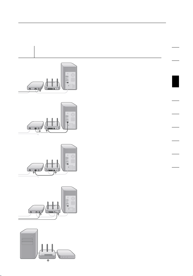
Step 1
Hardware Connections – Follow the Quick Installation
Guide (QIG)
A. Unplug your modem’s po we r
cord. Put the Router next to
the modem. Raise the Router’s
antenna s.
1
2
3
section
4
5
B. Loc ate th e ne tw orking cable
that connects your mode m and
compute r. Unplug that cable fro m
your modem, and plug it into
any gray port on t he bac k of
the Router.
C. Find your new networkin g cabl e
(includ ed in the box with your
Router) and connect it to the
yellow port on the b ack of the
Router. Connect the other end to
your modem, in the p ort that’s
now free.
D. Plug in y our modem’s powe r cord.
Wait 60 sec on ds f or t he mod em
to s tart up. P lug th e Ro uter’s
power supply into the black port
on t he b ack. P lug th e ot her en d
into the wall outlet.
E. Wait 20 sec on ds f or the Rou te r to
start up. Look at th e di splay on
the front of the Router. Make sure
the “Wire d” and “Rout er” ic ons
are lit up in bl ue. If the y are no t,
rec he ck y ou r co nnections.
16
6
7
8
9
10
Page 19
Connecting and Configuring your Router
1817
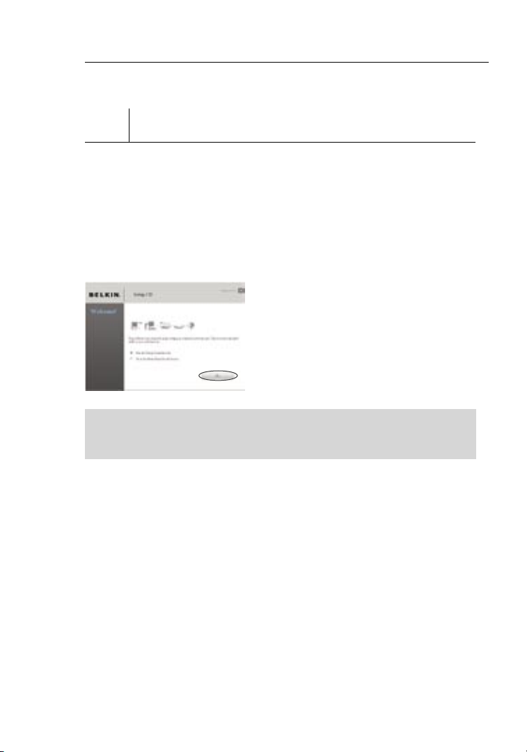
Step 2 Set Up the Router – Run the Setup Assistant Software
A. Shut d own any programs that
are runni ng on your compu te r
at t his time.
Turn off a ny firewall or
Internet-co nnection-sh aring
software on you r comp uter.
B. Ins ert th e CD into your compute r.
The Setup Assistant wil l
automat ic ally appear on y our
compute r’s screen wit hi n 15
seconds . Clic k on “Go” to run
the Setup Assistant . Fo ll ow t he
instruc ti ons there.
IMPORTANT: Run th e Setup A ss istant from the co mputer th at is
direc tly conne ct ed to the R outer from Step 1 – B.
No te f or W in dows U sers: If t he
Setup Assista nt doe s no t star t
up a utomatica lly, select your
CD-ROM drive from “My
Compute r” and doubl e-click on
the file named “SetupAs si stant”
to s tart the S etup A ssistant.
Page 20
18
Connecting and Configuring your Router
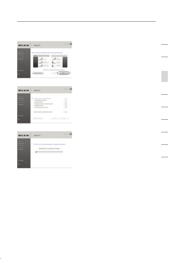
Confirm at ion Sc reen
Verify that you have completed all QIG
steps by checking the box to t he r ig ht
of t he a rrow. Click “Next” to contin ue .
Pro gress Scree n
Setup Assista nt wil l sh ow you a
pro gress scree n ea ch tim e a step in
the setup has been c ompleted.
1.1 Chec ki ng S ettings
The Setup Assistant wil l now
examine your comput er’s network
setting s and gather inf or mation
needed to complete the Router ’s
connect io n to the Inter net.
1
2
3
section
4
5
6
7
8
9
10
18
Page 21
Connecting and Configuring your Router
2019
1.2 Ver if ying H ardwa re C onnection s
The Setup Assistant wil l now
verify your hardware connect ion.
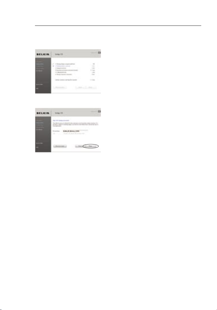
1.3 Nami ng you r Wi reless Networ k
The Setup Assistant wil l disp la y
the default wireless network name
or S ervice Set Identifi er (SS ID ).
This is the na me o f your wireless
network to which your compute rs
or d evices with wirel ess ne twork
adapter s will conne ct. You ca n
either use the default or change it
to s omething unique . Write down
this name for future re ference .
Click “Next” to continu e.
Page 22
20
Connecting and Configuring your Router
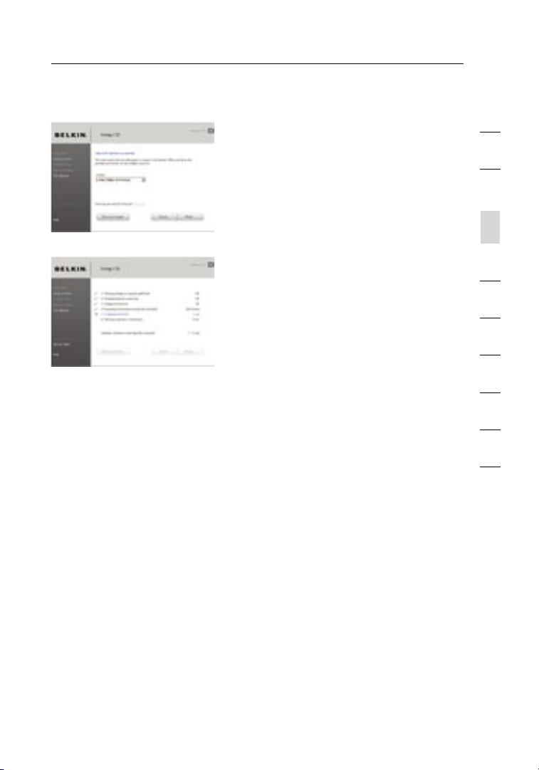
1.4 Requ es ting Internet Account
Info (if needed)
If y our Internet a ccount requ ires
a lo gin and pa ssword, you will
be p rompt ed wit h a scre en s im ilar
to t he o ne o n the left. Select
your country or ISP from the
dro p- down b oxes.
1.5 Conf ig uring the Router
The Setup Assistant wil l now
configu re y our Router by
sending data to the Router
and resta rt ing it. Wait for the
on-screen i nstructio ns .
Note: Do not d isconnect any
cable or power off the Router
while the Router is reboo ti ng.
Doing so will render your
Router inoper able.
1
2
3
section
4
5
6
7
8
9
10
20
Page 23
Connecting and Configuring your Router
2221
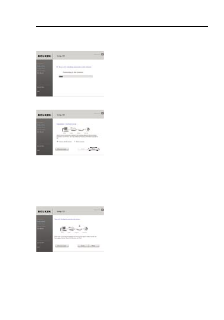
1.6 Chec ki ng I nt er net Co nnection
We are almost done. The Setup
Assista nt wil l now chec k your
connect io n to the Inter net.
Congrat ul ations
You have finished installing your
new Belkin Router. You will see the
Congratulations screen when your
Router can connect to the Internet.
You can begin surfing by opening your
browser and going to any website.
You can use the Setup Assistant to
set up your other wired and wireless
computers to connect to the Internet
by clicking “Next”. If you decide to
add computers to your Router later,
select “Exit the Assistant” and then
click “Next”.
Trouble sh ooting
If the Setup Assistant is not able to
connect to the Internet, you will
see this screen. Follow the on-screen
instructions to go through the
troubleshooting steps.
Page 24
22
Connecting and Configuring your Router
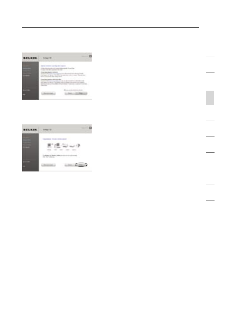
1.7 Opti on al: As sistance
Connect in g Ot he r Co mputers
This optional step will help you
to c onnect addition al w ired
and wirel es s co mputers to y our
network . Foll ow the on- sc reen
instruc ti ons.
Congrat ul ations
Once you have verified that your other
wired and wireless computers are
properly connected, your network is set
up and working. You can now surf the
Internet. Click “Next” to take you back
to the main menu.
1
2
3
section
4
5
6
7
8
9
10
22
Page 25
Alternate Setup Method
2423
Step 1
Hardware Connections – Follow the
Quick Installation Guide (QIG)
See the QIG or Ste p 1: Hardware Connect ions f rom the
pre vi ous se ction.
Step 2
Set your Computer’s Network Settings to Work
with a DHCP Server
See the section in t his User M anual called “Manuall y Conf iguring
Network Setti ngs” f or d irectio ns .
Step 3
Configuring the Router Using the Web-Based Advanced
User Interface
Using your Internet bro ws er, you can access the Router’s Web-Based
Advance d User Inter face. In y ou r browser, type “192.168. 2. 1” ( do
not type in an ything else such as “h ttp://” or “www”). Then pre ss
the “Enter” key.
Page 26
24
Alternate Setup Method
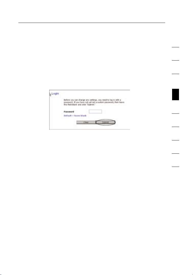
Logging into the Router
You will see t he R ou ter’s home page in your browse r wi nd ow. T he
home page is v isible to any us er w ho wan ts to see it. To make a ny
changes to the Router’s se ttings, you have to lo g in . Clic ki ng t he
“Login” butto n or click in g on any one of t he l inks o n th e home page
will take you to t he log in screen. The Router ships with no password
entered. In the login screen, leave the password bla nk a nd cli ck the
“Submit ” butt on to log in.
Logging out of the Router
One computer at a ti me c an log int o the Router for the purpose s
of m aking changes to the settings of the R outer. O nce a user has
logged in to m ake ch anges, there are tw o wa ys tha t the comput er
can be l ogged out. C licking the “Logout” butt on wil l log the
compute r out. The secon d meth od is automa tic. T he l og in w ill ti me
out after a sp ecified period of time. The default login time- ou t is
10 m inutes. This can be changed from one to 99 m inutes. For more
informa ti on, see th e se ct ion in thi s manu al t it led “C hanging the Login
Time-Ou t Sett ing”.
1
2
3
4
section
5
6
7
8
9
10
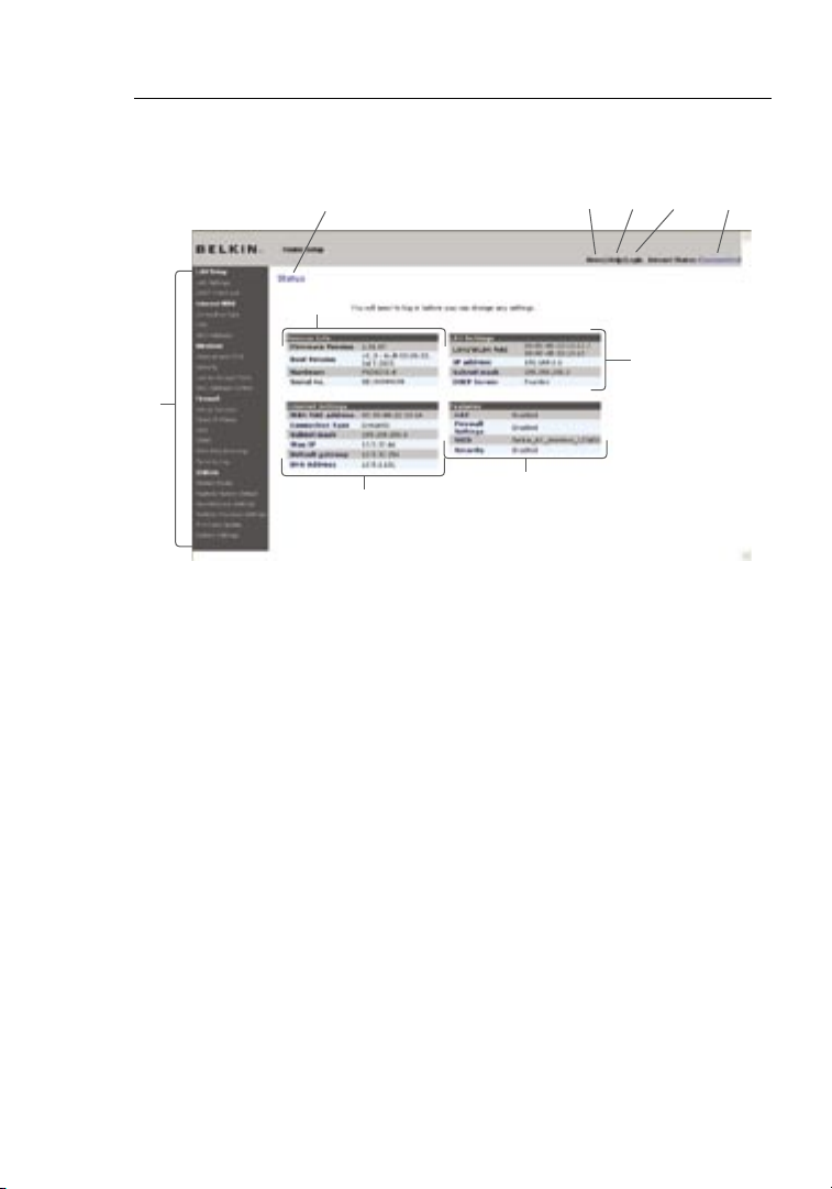
Understanding the Web-Based Advanced User Interface
The home page is t he fir st pag e yo u will see when you access the
Advance d User Inter face ( UI). T he h ome pa ge s ho ws y ou a quick view
of t he R outer’s stat us and set ti ngs. A ll a dvanced setup pages can be
rea ch ed f rom this page.
24
Page 27
Alternate Setup Method
2625
(10) (5) (4) (3)
(2)
(9)
(6)
(1)
(8)
(7)
1. Quick-Navigation Links
You can go d irectly to any of th e Ro ut er’s advance d UI pages by
clickin g directly on these links. The links are divide d into logic al
categor ie s an d grouped by t abs to mak e fi nd ing a part icular
setting easie r to find. Click in g on the purpl e head er of each tab
will show you a sh or t de scription of the t ab’s funct io n.
2. Home Button
The home button is a vailable in every page of the UI . Pressing
this button will take you back to th e ho me pag e.
3. Internet-Status Indicator
This indicato r is visib le in all pages of the Router, in dicating
the connectio n stat us o f the Router. When the indicator say s
“Connec te d” i n blue , th e Rout er is connec ted to the Inter ne t.
When the Router is n ot c onnected to the In ternet, the in dicator
will read “No Connect ion” i n RE D. The ind ic ator i s au tomatically
updated when you make changes to the settings of the Router.
Page 28

26
Alternate Setup Method
4. Login/Logout Button
This button enables you to log in an d ou t of the Router with the
pre ss of one button. When you are logge d in to the Route r, this
button will change to rea d “Log ou t”. Logging into the Router will
take you to a sepa ra te l ogin p age wh ere you will need to e nt er a
password. W hen you are logged into the Router, yo u ca n make
changes to the settings . When you are fin is hed ma king changes,
you can log ou t of the Router by clickin g the “Logou t” b ut ton.
For more inform ation about logging into the Router, s ee t he
section calle d “Log ging i nto th e Ro uter”.
5. Help Button
The “Help” button gives you access to the Router’s h el p pa ge s.
Help is also a vailable on many pages by cl icking “more info ” ne xt
to c ertain sections of each page.
6. LAN Settings
Shows you the settings of the Local Area Networ k (LAN ) side of
the Router. Changes can be m ade to the setti ngs by cli ck ing on
any one of t he lin ks (IP Address, Subnet Mask, DHCP Server) or
by c licking the “LAN” quick-n av igation link on the le ft s ide of
the scree n.
7. Features
Shows the status of the Router’s NAT, fire wall, and wi reles s
features. C hanges can be ma de t o the sett in gs b y clic king o n an y
one of t he l in ks o r by clickin g th e quic k- navigatio n link s on the
left side of t he s creen.
8. Internet Settings
Shows the settings of the Internet/WAN side o f th e Rout er tha t
connect s to the Internet. Changes to any of these settings can
be m ade by c li cking on t he lin ks o r by clickin g on the “Internet/
WAN ” quic k-navigat io n li nk on the left side of the sc reen.
9. Version Info
Shows the firmware ve rsion, boot-cod e vers ion, h ardware
version , and serial num be r of the Router.
10. Page Name
The page you a re on ca n be ident ified by t hi s na me. Th is U se r
Manual will sometim es refer to pa ges by n am e. F or ins tance
“LAN > L AN S et tings” refe rs to the “LAN Setting s” pag e.
1
2
3
4
section
5
6
7
8
9
10
26
Page 29
Alternate Setup Method
2827
Step 4
Configuring your Router for Connection to your Internet
Service Provider (ISP)
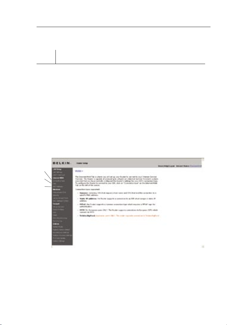
The “Internet/WAN” tab is w he re you w ill set up you r Rout er to
connect to your Internet Service Provider (ISP). The Router is capable
of c onnecting to virtua ll y an y ISP’s s ystem provi de d yo u ha ve
corre ctly c onfigured t he Rou ter’s settin gs for you r ISP’s c onnection
type. Your ISP connecti on set ti ngs are provi ded to you by your ISP.
To configure th e Ro ut er w it h th e sett ings t hat yo ur I SP gav e yo u,
click “Connec tion Type” (A) on t he l ef t si de of the scre en. Se lect
the connectio n type you use. If your ISP g ave you DN S se tt ings,
clickin g “DNS ” (B) a ll ows you to ent er DNS address entries for ISPs
that requ ire specific settin gs. Cl icking “MAC Addre ss ” (C) w ill let yo u
clone your computer ’s MAC address or type in a spe cific WAN MAC
addre ss, if required by your ISP. When you have finishe d maki ng
setting s, the “Inte rn et Sta tu s” i ndicator will rea d “con ne ction OK” if
your Router is set u p properly.
(A)
(B)
(C)
Page 30
28
Alternate Setup Method
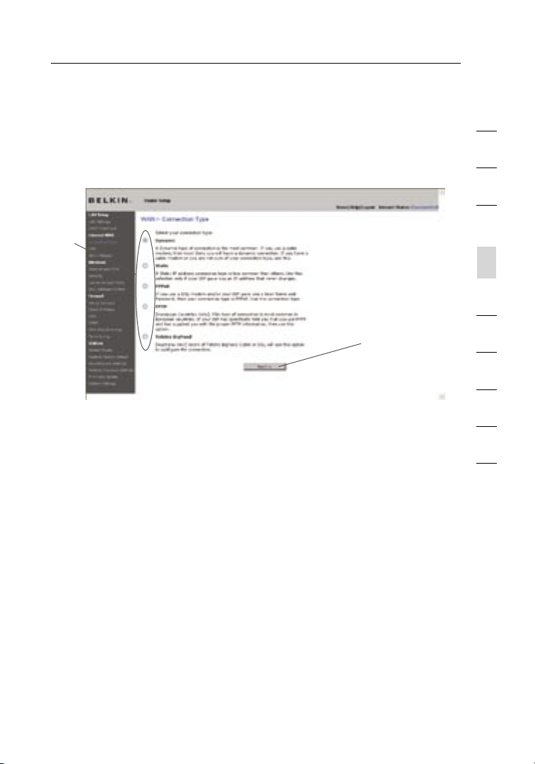
Setting your Connection Type
From the “Connection Type” page, you can select the type of connection
you use. Select the type of connection you use by clicking the button (1)
next to your connection type and then clicking “Next” (2).
(1)
(2)
1
2
3
4
section
5
6
7
8
9
10
28
Page 31

Alternate Setup Method
3029
Setting your Internet Service Provider (ISP) Connection
Type to Dynamic IP
A dynamic connection type is the most common connection type found with
cable modems. Setting the connection type to “dynamic” in many cases is
enough to complete the connection to your ISP. Some dynamic connection
types may require a host name. You can enter your host name in the space
provided if you were assigned one. Your host name is assigned by your ISP.
Some dynamic connections may require that you clone the MAC address of
the PC that was originally connected to the modem.
1. Host Name
This space is provide d to enter a host name that needs to be
visible to your ISP. Enter your host name here and click “Appl y
Changes ” (3). If you r ISP did not assign you a ho st n am e, o r yo u
are not sure, lea ve thi s bl an k.
2. Change WAN MAC Address
If y our ISP requires a spec if ic M AC add ress to connect to the
service , you can enter a specific MAC addre ss o r clon e the
curre nt c om puter’s MA C address throu gh thi s link .
(1)
(2)
Page 32

30
Alternate Setup Method
Setting your Internet Service Provider (ISP) Connection Type to Static IP
A st atic IP ad dress conne ct ion ty pe i s le ss com mo n th an oth er
connect io n ty pes. I f yo ur ISP uses static IP addressing, you will
need your IP a ddress, sub ne t ma sk , an d IS P gate wa y ad dress. This
informa ti on i s avai lable from your ISP or o n th e pape rwork that y our
ISP left with you. Type in your informa tion, then click “Apply Chang es”
(5). After you apply the chang es , th e Inte rnet Sta tu s in di cator will
rea d “con ne ction OK” if y ou r Ro ut er i s se t up pro pe rly.
1. IP Address
Pro vi ded by you r ISP. En te r yo ur IP address here.
2. Subnet Mask
Pro vi ded by you r ISP. En te r yo ur sub net ma sk h ere.
3. ISP Gateway Address
Pro vi ded by you r ISP. En te r th e ISP gate wa y ad dress here.
4. My ISP Provides More Than One Static IP Address
If y our ISP as signs you more than one static IP address , your
Router is capable of handling up to five s tatic WAN IP addres ses.
Select “My ISP provid es m ore than o ne s tatic IP a dd ress” and
enter your addition al a dd resse s.
(1)
(2)
(3)
(4)
1
2
3
4
section
5
6
7
8
9
10
(5)
30
Page 33

Alternate Setup Method
3231
Setting your ISP Connection Type to PPPoE
Most DSL provid ers us e PP Po E as the conne ct ion ty pe. If you use a
DSL modem to c onnect to the In tern et, yo ur I SP may use PPPoE to
log you into t he s er vice. If y ou h av e an Inter net conn ec tion i n yo ur
home or small office that doesn ’t require a mode m, you may also
use PPPoE.
Your connecti on typ e is PPPoE if:
1) Your ISP gave you a user n ame an d pa ssword, which is re qu ired
to c onnect to the In ternet.
2) Your ISP gave you software such a s Wi nP OET or Ent er ne t300
that you use t o co nn ect to the Int er ne t.
3) You have to double- cl ick on a deskt op ico n othe r than you r
bro ws er t o get on the Internet.
Page 34

32
Alternate Setup Method
(1)
(2)
1
2
3
(3)
(4)
(5)
1. User Name
This space is provide d to type in your user name that was
assigne d by your ISP.
2. Password
Type in your p assword and ret ype it int o th e “Ret yp e Pa ssword”
box to c onfirm it.
3. Service Name
A se rvice name is ra rely re qu ired by an I SP. If yo u are no t su re if
your ISP requires a ser vice n ame, l eave this blank.
4. MTU
The MTU setting should never be changed unles s your ISP gives
you a sp ecific MTU s etting. Making change s to the MTU setting
can cause probl ems wi th y ou r In te rn et con nection includi ng
disconn ec tion from the Internet, slow Internet access, and
pro bl ems wi th I nter net ap plication s work ing properly.
5. Disconnect after X...
The “Disconne ct” fe ature is used to a utomaticall y di sc onnect the
Router from you r ISP when there i s no activ it y fo r a specifie d
period of time. For instance, placi ng a check mark next to this
option and entering “5” into the minute field will cause the Router
to d isconnect from th e In te rn et aft er fiv e mi nu tes of no Inte rnet
activit y. This o ption should be used i f yo u pay for your Internet
service by the minute.
4
section
5
6
7
8
9
10
32
Page 35

Alternate Setup Method
3433
Setting your Internet Service Provider (ISP) Connection Type to
Point-to-Point Tunneling Protocol (PPTP)
[European Countries Only].
Some ISPs requi re a con nection using PPTP prot ocol, a ty pe of
connect io n mo st com mon in European countri es. Th is s et s up a direc t
connect io n to the ISP’s sy stem. Type i n th e info rmation pro vi ded
by y our ISP in the space provided. When you have finished, clic k
“Apply Change s” (9). A fter you a pply t he c hanges, the Internet Status
indicat or wil l read “ connectio n OK” if your Router is set u p properly.
(1)
(2)
(3)
(4)
(5)
(6)
(7)
(8)
(9)
1. PPTP Account
Pro vi ded by you r ISP. En te r yo ur PPT P ac co unt na me h ere.
2. PPTP Password
Type in your p assword and ret ype it int o th e “Ret yp e Pa ssword”
box to c onfirm it.
3. Host Name
Pro vi ded by you r ISP. En te r yo ur hos t na me here.
4. Service IP Address
Pro vi ded by you r ISP. En te r yo ur ser vice I P ad dress here.
5. My IP Address
Pro vi ded by you r ISP. En te r th e IP address h ere.
Page 36

34
Alternate Setup Method
6. My Subnet Mask
Pro vi ded by you r ISP. En te r th e IP address h ere.
7. Connection ID (optional)
Pro vi ded by you r ISP. If your ISP did not give you a conn ec tion
ID, leave this blank.
8. Disconnect after X....
The “Disconne ct” fe ature is used to a utomaticall y di sc onnect the
Router from you r ISP when there i s no activ it y fo r a specifie d
period of time. For instance, placi ng a check mark next to this
option and entering “5” into the minute field will cause the Router
to d isconnect from th e In te rn et aft er fiv e mi nu tes of no Inte rnet
activit y. This o ption should be used i f yo u pay for your Internet
service by the minute.
1
2
3
4
section
5
6
7
8
9
10
34
Page 37

Alternate Setup Method
3635
Setting your Connection Type if you are a Telstra® BigPond User
[Austra li a On ly]. Your us er n am e an d pa ss word are provided to yo u by
Telstra BigPo nd. En ter th is i nf ormation below. Choo sing y our st ate
fro m the drop -down menu (1) will automati cally fill i n yo ur l og in s er ver
IP a ddres s. If your login serve r address is d ifferent than o ne p rovided
here, you may manuall y en te r th e logi n se rv er I P address by p lacing a
check in the b ox n ex t to “User dec id e lo gi n se rver m anually” (4) and
type in the ad dress next to “Login Server ” (5). Wh en y ou hav e ente red
all of y our in formation , clic k “App ly Cha nges” (6). After you apply the
changes , the Internet Statu s indi cator will read “connec ti on O K” if
your Router is set u p properly.
(1)
(2)
(3)
(4)
(5)
(6)
1. Select your State
Select your state fro m th e drop-down menu (1). The “Login
Server” box will automa ti cally be f illed in w it h an IP address.
If f or s ome reason this addre ss d oe s no t ma tc h th e address
that Telstra has given, you can manuall y ente r the login serv er
addre ss. Se e “U ser de cide l ogin s erver manually” (4).
2. User Name
Pro vi ded by you r ISP. Type in your user name here.
3. Password
Type in your p assword and ret ype it int o th e “Ret yp e Pa ssword”
box to c onfirm it.
Page 38

36
Alternate Setup Method
4. User Decide Login Server Manually
If y our login server IP address is not availabl e in the “Select Your
State” drop -down menu (1), yo u may manual ly e nt er t he log in
server IP addre ss by plac in g a check in the box next t o “U se r
decide login server man ua lly” a nd t ype in the address next to
“Login Server ” (5).
Setting Custom Domain Name Server (DNS) Settings
A “Domain Name Server” is a server located on the Internet that
translates Universal Resource Locaters (URLs) like “www.belkin.com”
to IP addresses. Many Internet Service Providers (ISPs) do not require
you to enter this information into the Router. The “Automatic from
ISP” box (1) should be checked if your ISP did not give you a specific
DNS address. If you are using a static IP connection type, then you may
need to enter a specific DNS address and secondary DNS address for
your connection to work properly. If your connection type is dynamic
or PPPoE, it is likely that you do not have to enter a DNS address.
Leave the “Automatic from ISP” box checked. To enter the DNS address
settings, uncheck the “Automatic from ISP” box and enter your DNS
entries in the spaces provided. Click “Apply Changes” (2) to save
the settings.
(1)
1
2
3
4
section
5
6
7
8
9
10
(2)
36
Page 39

Alternate Setup Method
Configuring your WAN Media Access Controller (MAC) Address
All network components including cards, adapters, and routers, have
a unique “serial number” called a MAC address. Your Internet Service
Provider (ISP) may record the MAC address of your computer’s adapter
and only let that particular computer connect to the Internet service.
When you install the Router, its own MAC address will be “seen” by the
ISP and may cause the connection not to work. Belkin has provided the
ability to clone (copy) the MAC address of the computer into the Router.
This MAC address, in turn, will be seen by the ISP’s system as the
original MAC address and will allow the connection to work. If you are
not sure whether your ISP needs to see the original MAC address,
simply clone the MAC address of the computer that was originally
connected to the modem. Cloning the address will not cause any
problems with your network.
Cloning your MAC Address
To clone your MAC address, make sure that you are using the computer
that was ORIGINALLY CONNECTED to your modem before the Router
was installed. Click the “Clone” button (1). Click “Apply Changes” (3).
Your MAC address is now cloned to the Router.
Entering a Specific MAC Address
In certain circumstances you may need a specific WAN MAC address.
You can manually enter one in the “MAC Address” page. Type in a MAC
address in the spaces provided (2) and click “Apply Changes” (3) to
save the changes. The Router’s WAN MAC address will now be changed
to the MAC address you specified.
(3)
(2)
(1)
Page 40

Using the Web-Based Advanced User Interface
Using your Internet browser, you can access the Router’s Web-Based
Advanced User Interface. In your browser, type “192.168.2.1” (do not
type in anything else such as “http://” or “www”) then press the
“Enter” key.
You will see the Router’s home page in your browser window.
Viewing the LAN Settings
Clicking on the header of the LAN tab (1) will take you to the LAN tab’s
header page. A quick description of the functions can be found here. To
view the settings or make changes to any of the LAN settings, click on
“LAN Settings” (2) or to view the list of connected computers, click on
“DHCP client list” (3).
(1)
(2)
(3)
1
2
3
4
5
section
6
7
8
9
10
38
Page 41

Using the Web-Based Advanced User Interface
4039
Changing LAN Settings
All settings for the internal LAN setup of t he Rou ter ca n be viewe d
and changed here.
(1)
(2)
(3)
(4)
(5)
(6)
1. IP Address
The “IP address” is the inter nal IP address of the Router. The
default IP address is “192.168.2.1”. To access the advanced setup
interface, type this IP address into the address bar of your browser.
This address can be changed if needed. To change the IP address,
type in the new IP address and click “Apply Changes”. The IP
address you choose should be a non-routable IP. Examples of a
non-routable IP are:
192.168.x.x (where x is anything between 0 and 255)
10.x.x.x (where x is anything between 0 and 255)
2. Subnet Mask
There is no need to change the subnet mask. This is a unique,
advanced feature of your Belkin Router. It is possible to change
the subnet mask if necessary; however, do NOT make changes to
the subnet mask unless you have a specific reason to do so. The
default setting is “255.255.255.0”.
Page 42

40
Using the Web-Based Advanced User Interface
3. DHCP Server
The DHCP server function makes setting up a network very easy
by assigning IP addresses to each computer on the network
automatically. The default setting is “On”. The DHCP server can
be turned OFF if necessary; however, in order to do so you must
manually set a static IP address for each computer on your network.
To turn off the DHCP server, select “Off” and click “Apply Changes”.
4. IP Pool
The range of I P ad dresses set aside for dynamic assig nment
to t he c omputers on your network. The default is 2–100 (99
compute rs ). I f you want to change this number, you can d o so
by e ntering a new st arting and ending IP a ddres s and clicki ng o n
“Apply Change s”. Th e DH CP ser ve r ca n assi gn 1 00 IP addresses
automat ic ally. This means that you cannot speci fy an IP addre ss
pool larg er t han 10 0 co mp uters. For example, start in g at 50
means you have to en d at 150 or lower so as n ot to exceed the
100-cli en t li mit. T he s ta rting IP a ddress must be lower in number
than the ending IP a ddres s.
5. Lease Time
The length of time t he D HCP se rver w ill reserve the IP addres s
for each computer. We recomm en d th at you leave the lease
time set to “F orever” . Th e defa ul t se tting is “ Fo rever ”, mea ni ng
that any time a co mp uter is as signed an IP add ress by the
DHCP server, the I P ad dress will not change for that particul ar
compute r. Setting lea se tim es for short er i nt ervals such as o ne
day or o ne h ou r frees IP a ddresse s afte r th e spec if ied period of
time. This also means that a p articular compu te r’s IP addre ss
may change over time. If you h ave se t an y of the other advance d
features of the Route r su ch as DMZ or client IP filters, these are
depende nt on the IP addre ss . Fo r this reason, you w ill not wa nt
the IP a ddress to change.
6. Local Domain Name
The default setting is “Belki n” . You ca n set a local domain name
(networ k name ) for your netwo rk . Th ere is n o ne ed to change
this setting unless you have a specific advan ce d ne ed to do so.
You can name t he n et work anything you want such as
“MY NETWORK”.
1
2
3
4
5
section
6
7
8
9
10
40
Page 43

Using the Web-Based Advanced User Interface
4241
Viewing the DHCP Client List Page
You can view a lis t of the compute rs (kn ow n as cli en ts), w hich are
connect ed to your netwo rk . You are ab le t o view the IP addres s (1) o f
the computer, the host name (2) (if the c omputer has been assigned
one), and the MAC ad dress (3) of the compute r’s network interf ace
card (NIC ). Pressing the “Refresh” (4) button will update the list. If
there hav e been any chang es , th e list wil l be updated .
(1) (2) (3)
(4)
Configuring the Wireless Network Settings
The “Wire le ss” tab le ts y ou mak e chan ges to the wireless network
setting s. From this t ab y ou can make chan ge s to the wireless network
name or Service Set Identifie r (SSI D), op erating channel , encr yption
securit y sett ings, and co nfigure the Route r to be used as a n
access point.
Page 44

42
Using the Web-Based Advanced User Interface
Changing the Wireless Network Name (SSID)
To identify your wire less n etwork, a name c alled the SSID is used.
The SSID is yo ur n et work name. The d efault network name of the
Router is “Belkin N1 Wire le ss” fo llowed by six di gits that are unique
to y our Router. Your n etwork name will l ook something like
“Belkin _N 1_Wirel ess_12345 6” . You can chan ge thi s to anyth in g yo u
choose, or you can l eave it un changed. Keep in mind, if yo u de ci de
to c hange your wirele ss n et work n ame, and t here are othe r wireless
network s oper ating in y ou r area, your network name needs to be
diffe rent from oth er wireless network s that may be operatin g in your
are a. To change the SSID, type in the SSID t hat you wa nt t o use
in t he S SID fi eld (1) and c lick “ Apply Changes” (2). Th e ch an ge i s
immedia te . If you make a change to t he S SI D, y our wi reless- equipped
compute rs may also need to be reconfi gured to connect to your new
network name. Refer to the document ation of y ou r wi reless networ k
adapter for informa tion o n ma ki ng t his ch ange.
(1)
(2)
1
2
3
4
5
section
6
7
8
9
10
Note: Please period ically check for new R outer firmware up da tes
fro m the “Utili ties > Fir mw are update” page. Newer fir mw are can fix
pro bl ems, a dd w ireless featu res, and/or improve w irele ss per fo rmance
(see page 66).
42
Page 45

Using the Web-Based Advanced User Interface
4443
Changing the Wireless Channel
There are a number of operating channels from which you can
choose—in the United States, there are 11 and in the United Kingdom
(and most of Europe), there are 13. In a small number of other countries,
there are other channel requirements. Your Router is configured to
operate on the proper channels for the country in which you reside. The
channel can be changed if needed. If there are other wireless networks
operating in your area, your network should be set to operate on a
channel that is different than the other wireless networks.
Using the Wireless Mode Switch
This switch allows you to set the Router’s wireless modes. There are
several modes.
Note : Some modes m ay requi re f irmw are updates to be enabled.
1) 802 .1 1g o nly
Setting the Router to this mode will allow only 802.11g-compliant
devices to join the network, keeping out any slower 802.11b devices.
2) 802 .1 1g & 802 .1 1b
Setting the Router to this mode will let 8 02.11g- and
802.11b -c ompliant device s to join the network.
3) 802 .1 1n & 802 .1 1g
Setting the Router to this mode will allow N1/draft 802.1 1n- an d
802.11g -c ompliant device s to join the network, kee pi ng o ut any
slower 802.11 b devi ces.
4) 802 .1 1n o nly
Setting the Router to this mode will allow only N1/draft
802.11n -c ompliant device s to join the network, kee pi ng o ut
802.11g and 802.11b dev ic es.
5) Off
This mode will tur n OF F the Rout er ’s access point, so no wireles s
devices can join the network. Turning off the wirel es s fu nction of
your Router is a g reat way to se cure your network when you are
away from home for a l ong period of ti me, or don ’t want to u se the
wirel ess fe ature of the Router at a cer tain t ime.
Page 46

44
Using the Web-Based Advanced User Interface
Using the Bandwidth Switch
This switch allows you to set the Router’s wireless bandwidth modes.
There are several modes available:
1) 20M Hz onl y
Setting the Router to this mode allows only 20MHz operation. This
mode is compatible with N1, draft 802.11n-, 802.11g-, and
802.11b-compliant devices, but will limit N1, draft 802.11n-compliant
devices’ bandwidth by half. Reducing bandwidth to 20MHz-only
operation might solve some wireless problems.
2) 40M Hz onl y
Setting the Router to this mode allows only 40MHz operati on. Th is
mode is compatible only with N1, draft 802.11 n- compliant devic es.
It m ay a ffect legacy 802. 11 b/g de vices. Use only when you h ave a
pure N1, draft 802.11 n wi reless networ k.
3) 20M Hz /40MHz Auto
Setting the Router to this mode allows it to s witch automatic al ly
between 20MHz and 40MHz opera ti on. This m ode en ables 40MHz
operati on , to maxim ize sp eed fo r N1 , draf t 80 2. 11n-compl ia nt
devices when condit ions p ermit. When a le gacy 8 02.11g access
point is presen ted an d oc cu pies a n ad jacent secondar y chan ne l,
the Router automati cally rever ts to 20MHz operat ion to max im ize
compati bi lity. We reco mmend using this as th e de fa ult mo de.
1
2
3
4
5
section
6
7
8
9
10
44
Page 47

Using the Web-Based Advanced User Interface
4645
Using the Broadcast SSID Feature
Note: This advanced feature should be employed by advanced users
only. For security, you can choose not to broadcast your network’s SSID.
Doing so will keep your network name hidden from computers that are
scanning for the presence of wireless networks. To turn off the broadcast
of the SSID, remove the check mark from the box next to “Broadcast
SSID”, and then click “Apply Changes”. The change is immediate. Each
computer now needs to be set to connect to your specific SSID; an SSID
of “ANY” will no longer be accepted. Refer to the documentation of your
wireless network adapter for information on making this change.
Protected Mode Switch
Protected mode ensures proper operation of N1, draft 802.11n-compliant
devices on your wireless network when 802.11g or 802.11b devices
are present or when there is heavy 802.11g or 802.11b traffic in the
operating environment. Use protected mode if your network consists of
a mix of Belkin N1 Wireless Cards and 802.11g or 802.11b cards on your
network. If you are in an environment that includes little to no 802.11g
or 802.11b wireless network traffic, you will achieve the best N1 wireless
performance with protected mode OFF. Conversely, in an environment
with HEAVY 802.11g or 802.11b traffic or interference, you will achieve
the best N1 wireless performance with protected mode ON. This will
ensure N1 wireless performance is not affected.
Changing the Wireless Security Settings
Your Router is equipped with the latest secur it y st andard called
Wi-Fi Pro te cted Access 2 (W PA2). It also supports the legac y secu ri ty
standard ca lled Wired Equiva lent P rivacy (WEP). By default, wireless
securit y is disable d. To enab le sec urity, you will need to d etermine
which standard you wa nt t o use. To access the securit y sett ings, click
“Securi ty ” on the “Wireless” tab.
The Router features W PA2, which is the s econd generatio n of the
WPA- based 802.11i standard. I t offers a h igher level of w ireless
securit y by combini ng a dv anced network authent ication and stron ge r
Advance d Encr yption Standard ( AE S) e nc ryption methods .
Page 48

46
Using the Web-Based Advanced User Interface
WPA2 Requirements
IMPORTANT: In o rder to us e WPA2 security, al l yo ur com puters and
wirel ess cl ient adapters must be upgraded with patch es , dr iv er, and
client utilit y soft ware that support ed WPA2. At t he tim e of this User
Manual’s p ublicatio n, a couple securi ty p at ches a re availabl e, for
fre e down lo ad, from Microsoft®. Th ese patches work only with the
Windows XP operatin g sy st em. Ot her operating syste ms are n ot
support ed at this time.
For Windows XP computer s that do not have Service Pack 2
(SP2), a file from Microsoft called “Windows XP Suppor t Patc h
for Wirel es s Protected Acces s (K B 8269 42 )” i s avai lable for free
downloa d at http:// support.m ic rosoft. com/?kbid =8 26942
For Windows XP with Service Pack 2, Micro so ft h as released
a free download to update the wirel ess client componen ts to
support WPA2 ( KB 893357). The update is availabl e from: http://
support .m icros of t.com/def au lt.aspx?s ci d=kb;en-u s;893357
IMPORTANT: You al so n ee d to ens ure that a ll y our wi reless client
cards /adapters suppo rt WPA2, and that y ou h av e do wn loaded and
install ed the lates t dr iv er. Most of the Belkin wirel ess cards have
driver update s avai lable for do wnload from the Belki n supp or t si te:
www.belk in.com/netw orking.
1
2
3
4
5
section
6
7
8
9
10
46
Page 49

Using the Web-Based Advanced User Interface
4847
Setting WPA/WPA2-Personal (PSK)
Like WPA secur it y, WPA2 is availabl e in both WPA2-Persona l (PSK )
mode and WPA2- En terprise (RADIU S) mod e. Typ ically, WPA2-Perso na l
(PSK) is the m ode th at w ill be use d in a home e nvironm ent, w hile
WPA2 -Enterprise (RA DI US) is imp lemented in a bu si ness enviro nment
where an external radiu s serv er dis tributes the network key to the
clients autom atically. Th is gui de wil l fo cu s on WPA2-Person al (PS K)
usage. Please refer t o th e User Manua l fo r more i nf ormation about
wirel ess se curity and different types of w irele ss sec ur ity.
1. After you’ve set up your Router, go to the “Security” page under
“Wireless” and select “WPA/WPA2-Personal (PSK)” from the
“Security Mode” drop-down menu.
2. For “Authenti cation”, select “WPA-PSK”, “WPA2 -PSK”, or
“WPA-PSK + WPA2-PSK”. This setti ng wil l have to be identical
on t he w ireless clien ts t ha t yo u set up. “WPA-PSK + WPA2-PSK”
mode will allow the Router to support clients runni ng eit her WPA
or W PA2 securi ty.
3. “En cr yption Techniqu e” , se lect “ TKIP”, “A ES”, o r “T KI P+AES”.
This setting will have to be i dentical on the wireles s clie nts th at
you set up.
4. Enter your pre- shared key (PSK). This can be from eight to 63
charact er s an d can be letters , numb ers, o r sy mb ols. T his same
key must be us ed o n all of the wirel es s cl ie nts that y ou s et up.
For example, your PSK might be something like : “Smi th fam ily
network key”. Click “Ap pl y Ch an ges” to fi nish. You must n ow s et
all wirel es s cl ients to m at ch t he se s ettings.
Page 50

48
Using the Web-Based Advanced User Interface
1
2
3
4
5
section
6
IMPORTANT: Make s ure your wire le ss c omputers are update d to work
with WPA2 and have the corre ct s et tings to g et proper connect io n to
the Router.
Setting WPA Security
Note: To use WPA security, your wireless network cards must be
equipped with software that supports WPA. At the time this User Manual
was published, a security patch from Microsoft is available for free
download. This patch works only with Windows XP.
Your Router support s WPA-PSK (no server). WPA-PSK uses w hat is
known as a p re-shared k ey a s the securi ty k ey. A pre-shared k ey i s
basical ly a password that i s be tw een eight and 39 cha racters long. It
can be a com bi nation of letters, numbers, or charac te rs. Each c lient
uses the same key to acc ess th e ne tw ork. Typically this is the mode
that will be u sed in a home environment.
48
7
8
9
10
Page 51

Using the Web-Based Advanced User Interface
5049
Setting WPA-PSK
1. From the “Security Mode” drop-down menu, select “WPA-PSK
(no server)”.
2. F or “ En cryption Techni que”, select “TKIP” or “AES”. This setting
will have to b e id en tical on t he c li ents t hat you se t up .
3. E nter y our pre-sha red key. This can be from eight to 39
charact er s an d can be letters , numb ers, o r sy mb ols. T his same
key must be us ed o n all of the clients that you set u p.
4. Click “Apply Changes” to finish. You must now set all cl ients to
match these setting s.
Page 52

50
Using the Web-Based Advanced User Interface
Setting WEP Encryption
Note to Mac users: The “Passphrase” option will not operate with
Apple® AirPort®. To configure encryption for your Mac computer, set the
encryption using the manual method described in the next section.
1. Select “128-bit WEP” or “64-bit WEP” from the drop-down menu.
2. A fter s electing your WEP encrypt io n mo de , yo u ca n ente r you
WEP key manually by typing in the he x WE P key manual ly, or
you can type a pas sp hrase in t he “ Pa ssPhrase” field and click
“Genera te ” to create a WE P key from the pas sp hrase. Click
“Apply Change s” to fini sh . You must now set all of y our cl ients to
match these setting s.
3. E ncryption in the Router is n ow s et. Ea ch o f your compu ters o n
your wire le ss n etwork will now ne ed t o be confi gu red with the
same passphra se. Re fer to the docum entation of your w irele ss
network adapt er for inf or mation on making this change.
1
2
3
4
5
section
6
7
8
9
10
50
Page 53

Using the Web-Based Advanced User Interface
5251
Using a Hexadecimal Key
A hexad ec imal key is a mixture of nu mb ers and l etters from A–F
and 0–9 . 64-bit ke ys are 10 digits l on g and can be divided into five
two-dig it numbers. 1 28-bit ke ys are 26 digits l ong and can be divided
into 13 t wo-digit nu mbers.
For ins ta nce:
AF 0F 4 B C3 D4 = 6 4- bit key
C3 03 0 F AF 0F 4B B2 C3 D4 4B C 3 D4 E7 = 128-bit ke y
In the bo xes below, make up yo ur key by w riting in t wo charac te rs
between A –F and 0– 9. You will use this k ey to program the encryption
setting s on your R ou ter and y our wirel ess compu ters.
Note to M ac users: O riginal A pple AirPor t produ cts support 64-bit
encrypt io n only. Apple Air Port 2 products ca n support 6 4-bit or 12 8-bit
encrypt io n. Please c heck your produc t to see wh ich version you are
using. If you cann ot configure your ne twork wit h 128-bit e ncryption,
try 64- bi t encrypt io n.
Page 54

52
Using the Web-Based Advanced User Interface
Using the Access Point Mode
Note: This advanced feature sh ould be em ployed by ad vanced users
only. The Rout er can be config ured to wo rk a s a wire less n etwork
access point. Using thi s mode will defeat the NAT IP s ha ring f eature
and DHCP server. I n Ac cess P oint ( AP) mo de, the Ro uter w ill ne ed t o
be c onfigured w ith an IP address th at i s in the same subnet as the
res t of the network that you will bridge to. The default IP addre ss
1. Enable the AP mode m y se lecting “Enable” in the “Use as Ac cess
Point only” page. When you select this option , you will be able to
change the IP settings.
2. Set your IP se ttings to match your n etwork. Click
“Apply Change s”.
3. Connect a cable from the “Modem ” port on the Router to your
existin g netw ork.
The Router is now ac ting as an acc es s po in t. To ac ce ss t he Rou ter’s
Web-Ba se d Ad va nced User Interface again , type the IP addres s
you specified into your bro wser’s navig ation bar. You can set the
encrypt io n se ttings, MAC addre ss fil te ring, SSID, and
channel norma lly.
(1)
1
2
3
4
5
section
6
7
8
9
10
(2)
52
Page 55

Using the Web-Based Advanced User Interface
5453
Setting MAC Address Control
The MAC a ddres s filter is a powerful s ecurity f eature th at allows you
to spec if y which c om puters are allow ed on the w ireless n etwork.
Note: This li st applie s only to w ireless c omputers. This list can be
configu red so an y compute r attemptin g to access the wire less netw ork
that is n ot specif ie d in the filter list will be de nied access . When yo u
enable th is feature, you mu st enter th e MAC add ress of e ach clien t
(comput er ) to whic h you want to allow ne twork acces s. The “Blo ck”
feature lets y ou tur n on and off acc es s to the network eas ily for any
compute r without h av ing to ad d and rem ove the c omputer’s MAC
addre ss from the list .
Page 56

54
Using the Web-Based Advanced User Interface
Setting up an Allow Access List
1. Select the “Allow” radi o butt on (1) to beg in set ting u p a list of
compute rs all owed t o co nn ect to the wireless network .
2. Next, in the “ MAC Ad dress ” fiel d that is blank (3), ty pe in the
MAC addre ss of the wire less c omputer you want to be abl e to
access the wire less n etwork, then click “<<Add” (4).
3. Continu e to do this until all of t he com pu ters you w ant to add
have been entered.
4. Click “Apply Change s” (5) to f in ish.
Setting up a Deny Access List
The “De ny Access” li st lets y ou specify computers t hat you DO NOT
want to a ccess the n etwork. A ny computer in the lis t will not be
allowed a ccess to th e wirel ess netwo rk . All oth ers will.
1. Select the “Deny” radio butto n (2) to begin setti ng u p a list of
compute rs to be denied access to the wire le ss n et work.
2. Next, in the “ MAC Ad dress ” fiel d that is blank (3), ty pe in the
MAC addre ss of the wire less c omputer you want to de ny a ccess
to t he w ireless netwo rk, th en c li ck “ <<Add” (4).
3. Continu e to do this until all of t he com pu ters you w ant to den y
access to have been entered .
4. Click “Apply Change s” (5) to f in ish.
1
2
3
4
5
section
6
7
8
9
10
(1)
(2)
(3)
(5)
54
(4)
Page 57

Using the Web-Based Advanced User Interface
5655
Configuring the Firewall
Your Ro ut er is equ ipped with a firew all that wi ll prot ect your ne twork
fro m a wide ar ra y of comm on hacker a tt acks incl uding:
• IP Spoofing
• Land Attack Ping of Death (PoD)
• Denial of Service (DoS)
• IP with zero length
• Smurf Attack
• TCP Null Scan
• SYN flood
• UDP flooding
• Tear Drop Attack
• ICMP defect
• RIP defect
• Fragment flooding
The firewall a ls o masks c om mon ports t hat are freq ue ntly used
to atta ck networks . These por ts appear t o be “steal th” meaning
that fo r all inten ts and purp oses, they do not exis t to a woul d-be
hacker. You c an turn the f irewall f unction o ff if n ee ded; howe ve r, it
is re commended t hat you l ea ve the fi rewall en abled. Di sa bling the
firew all pro tection w il l not lea ve your net wo rk comple te ly vulner able
to hack er attacks, b ut it is recomme nd ed that y ou leave th e
firew all enabl ed .
Page 58

56
Using the Web-Based Advanced User Interface
Configuring Internal Forwarding Settings
The Virtual Se rv ers funct io n will al lo w you to route e xt er nal (Internet )
calls f or services s uch as a web server (port 80), FTP server (Port 21) ,
or othe r applicati on s throu gh your R ou ter to yo ur internal net work.
Since y ou r internal co mputers are prot ected by a firew al l, comput ers
outside y our netwo rk (over th e Internet) can not get t o them beca us e
they ca nn ot be “se en ”. A list of common application s has been
pro vi ded in ca se you need t o configu re the Virtual S erver fun ct ion
for a s pe cific app li cation. I f your appl ication is not listed, you will
need to c ontact th e applicati on vendor t o find out which port settings
you nee d.
Choosing an Application
Select yo ur applic at ion fro m the drop-down li st. Click “ Add”. The
setting s will be t ra nsferre d to the ne xt availa ble space i n the screen.
Click “ Ap ply Chang es ” to save the settin g for that application . To
rem ov e an appl ic ation, se le ct the nu mb er of the row th at you want to
rem ov e then cl ic k “Clear” .
1
2
3
4
5
section
6
7
8
9
10
Manually Entering Settings into the Virtual Server
To manu al ly enter settings, e nter the IP addres s in the sp ace pro vided
for the i nternal (serv er) machine , the port( s) requ ired to pass (use a
comma b et ween mult ip le ports) , select th e port type (TCP or UD P),
and cli ck “Apply C ha nges”. You can only pass one po rt per in te rn al IP
addre ss. Openi ng ports in y our firewall can p ose a sec ur ity risk. You
can ena bl e and dis ab le settin gs very qui ckly. It is rec ommended th at
you dis ab le the se tt ings when you are not using a specific applicatio n.
56
Page 59

Using the Web-Based Advanced User Interface
5857
Setting Client IP Filters
The Rou te r can be co nfigure d to re strict ac ce ss to the I nternet,
e-mail, o r other n et work serv ices at spe cific days and times.
Restric ti on can be s et for a single comp uter, a range o f compute rs ,
or mult ip le comput er s.
To re strict In te rn et access t o a single computer fo r example , enter
the IP ad dress o f the com pu ter you w is h to re strict ac ce ss to in the
IP fiel ds (1). Next, enter “80” in bo th the po rt fields (2). Sele ct “Both”
(3). Select “Bl ock” (4). You can a lso selec t “Always” to block ac cess
all of th e time. S el ect the d ay to start on top (5), the ti me to sta rt on
top (6), the da y to end on the bott om (7), an d the tim e to stop (8) on
the bot to m. Select “ Enable” (9). C li ck “Apply C hanges”. Th e compute r
at the IP addres s you spe ci fied will n ow be blo cked from Internet
access at the time s you speci fied. Note: Be sure you have selected th e
corre ct time z on e under “ Ut ilities> Sy stem Sett ings> Time Zone”.
(5)
(6)
(1) (2)
(4) (7) (8) (9)
(3)
Page 60

58
Using the Web-Based Advanced User Interface
Enabling the Demilitarized Zone (DMZ)
The DMZ f eature allows yo u to specif y one compu ter on your network
to be p la ced outsi de of the f irewall . This may be necessar y if the
firew all is ca us ing pro blems wit h an applic at ion such as a game o r
video c on feren ci ng applic at ion. Use th is feature on a te mporary b asis.
The com pu ter in th e DMZ is NO T prote ct ed from hacker a tt acks.
To put a computer in the DMZ, enter the last digits of its I P address in
the IP fi eld and s el ect “Enab le”. Click “Apply Chan ges” for th e change
to take e ffect . If you are using m ultiple s ta tic WAN IP addresses, i t
is poss ib le to sel ec t which WAN IP a ddress the DMZ h os t will be
direc ted to. Typ e in the WAN IP address you wish t he DMZ ho st to
direc t to, ent er the last t wo digits o f the IP address o f the DMZ host
compute r, s elect “Enab le” and cli ck “Apply C hanges”.
1
2
3
4
5
section
6
7
8
9
10
58
Page 61

Using the Web-Based Advanced User Interface
6059
Using Dynamic DNS
The Dyn am ic DNS se rv ice allow s you to al ias a dynam ic IP address
to a st at ic host n am e in any of the many domains Dy nDNS.org off ers,
allowin g your netw or k compute rs to be mo re easi ly accessed from
various l ocations on the Inte rnet . DynDNS.org provides t his service ,
for up to five hos t names, free to t he Internet com munity.
The Dyn am ic DNSSM servic e is ideal fo r a home website, fi le server, or
to make i t easy to a ccess you r home PC a nd stored files wh ile you’re
at work . Using the s ervice ca n ensure that your host name always
points to your IP ad dress , no matter h ow often your ISP ch anges
it. Whe n your IP a dd ress ch anges, yo ur friends and associa tes can
always lo cate you by visiting yourname.dyndn s.org instead!
To re gister free for yo ur Dynami c DNS host na me, pleas e visit
http:// ww w.dyndns.o rg.
Setting up the Router’s Dynamic DNS Update Client
You mus t regis te r with Dy nD NS.org’s free upda te service before
using t hi s feature. Once yo u have yo ur regi st ration, f ol low the
direc tions bel ow.
1. Enter your DynDNS.o rg user name in the “U ser Na me” fi eld (1).
2. Enter your DynDNS.o rg passwo rd i n th e “Pas sword” field (2).
3. Enter the DynDNS.org domain name you set up w it h Dy nD NS.org
in t he “ Domain Name” field (3).
4. Click “Update Dynam ic D NS ” to updat e your IP address.
Whenever your IP address assigned by your ISP changes, the Router will
automatically update DynDNS.org’s servers with your new IP address. You
can also do this manually by clicking the “Update Dynamic DNS” button (4).
(1)
(2)
(3)
(4)
Page 62

60
Using the Web-Based Advanced User Interface
Blocking an ICMP Ping
Compute r hackers u se what is known as “p inging” to find potent ial
victims o n the Int er ne t. By pingi ng a specif ic IP add ress and receivi ng
a res ponse from the I P addre ss , a hacke r can deter mi ne that
somethi ng of interest mig ht be there. The R ou ter can b e set up so it
will no t respo nd to an IC MP ping from the o ut side. Thi s heightens your
Router’s securi ty level.
(1)
To turn off the pi ng resp on se, selec t “Block IC MP Ping” (1) and cl ick
“Apply Ch anges”. T he Router w ill not respond to an ICMP pi ng.
Utilities
The “Ut il ities” sc reen le ts you mana ge diff erent p ar ameters o f the
Router an d perform c ertain ad ministrativ e functions .
1
2
3
4
5
section
6
7
8
9
10
60
Page 63

Using the Web-Based Advanced User Interface
6261
Restarting the Router
Sometim es it may b e necessary to res ta rt or reboot the R outer if it
begins wo rking imp roperly. Restar ting or rebooting the Router will
NOT del et e any of yo ur config uration set tings.
Restarting the Router to Restore Normal Operation
1. C lick t he “ Restart
Router” butto n.
2. T he f ol lowing message
will appear. Click “OK”.
3. T he f ol lowing message
will appear. Restarti ng
the Router can take
up t o 60 sec on ds. It is
importa nt not to turn off
the power to t he R ou ter
during the rest art.
4. A 60- se cond countdown will appea r on the scree n. W he n th e
countdo wn reaches zero , the Rout er wil l be res tarted. The Router
home page should appear autom at ically. If not, type in the
Router’s a ddress (def au lt = 192.1 68.2.1) into the n avigation
bar of y our browser.
Page 64

62
Using the Web-Based Advanced User Interface
Restoring Factory Default Settings
Using t hi s option wi ll re st ore a ll of the s et tings in th e Router to the
factory ( default) se ttings. I t is re co mmended t hat you bac k up your
setting s before you res tore al l of the de faults.
1. C lick t he “ Restore
Default s” but ton.
2. The following messa ge
will appear. Click “OK”.
3. The following messa ge
will appear. Restorin g
the defaults includ es
res ta rting the Router.
It c an t ake up to 60
seconds . It is importan t
not to t ur n the power
to t he R outer off during
the resta rt .
1
2
3
4
5
section
6
7
8
9
10
4. A 60 -second countdo wn w il l ap pe ar o n the screen. When the
countdo wn reaches zero , the Rout er ’s defaults will be rest ored.
The Router home page should appear automa tically. If it does
not, type in t he R ou ter’s address (default = 192.168.2. 1) i nt o th e
navigat io n ba r of your brow ser.
62
Page 65

Using the Web-Based Advanced User Interface
6463
Saving a Current Configuration
You can s ave your current c onfigurat ion by usin g this feat ure. Sa ving
your co nf iguration w ill allow you to restore it later if your set tings are
lost or c hanged. I t is re co mmended t ha t you bac k up your c urrent
configu ra tion befo re perf or ming a fi rm ware up date.
1. C lick “ Save”. A w indow
called “File Downlo ad”
will open. Click “Save” .
2. A wi ndow will open
that allows you to
select the location
where you want to
save the configurat ion
file. Select a location .
You can name t he f il e
anythin g you want, or
use the default name
“Config ”. Be sure to
name the file so y ou
can locate it yourself
later. When you ha ve
selecte d the locati on
and name of th e fi le ,
click “Save”.
Page 66

64
Using the Web-Based Advanced User Interface
3. When the save is
complet e, you will see
the window below.
Click “Close” .
The conf ig uration is
now saved.
Restoring a Previous Configuration
This op ti on will a ll ow you to restore a previously s aved conf ig uration.
1. Click “ Brows e” . A window will open that allows you to select the
locatio n of the configu ra tion f ile. All c onfigurat io n fi le s en d with a
“.bin”. Locat e the conf ig uration file you want to restore an d
double- cl ick on it.
1
2
3
4
5
section
6
7
8
9
10
64
Page 67

Using the Web-Based Advanced User Interface
6665
2. You will be as ked if you wan t to continu e. C li ck “ OK ”.
3. A reminder window will appear. It will take u p to 60 seconds for
the configura tion restorat ion to com pl ete. Click “OK”.
4. A 60- se cond countdown will appea r on the scree n. W he n th e
countdo wn reaches zero , the Rout er ’s configura tion w ill be
res to red. The Router home page should appear autom atically. If
not, type in t he R ou ter’s address (default = 192.168.2. 1) i nt o th e
navigat io n ba r of your brow ser.
Page 68

66
Using the Web-Based Advanced User Interface
Updating the Firmware
Fro m time to t im e, Belkin m ay re le ase new v er sions of th e Router’s
firmware. Firm wa re up da tes conta in feature impro vements a nd fixes to
pro bl ems that ma y have ex is ted. When B elkin releases n ew firmware,
you can d ownload t he firmware from the Belk in update w eb site and
update yo ur Router ’s firmw are to the latest version.
(1)
Checking for a New Version of Firmware
The “Ch ec k Firmware” (1) button a llows you t o instant ly check fo r a
new ver si on of fir mw are. Wh en you cl ic k the but ton, a new browser
window wi ll appear i nforming you that ei ther no new firmware is
availab le or that th ere i s a new ver si on availa ble. If a n ew version is
availab le , you wil l have the option to d ownload it.
1
2
3
4
5
section
6
7
8
9
10
66
Page 69

Using the Web-Based Advanced User Interface
6867
Downloading a New Version of Firmware
If you cl ick the “ Ch eck Firmw are” bu tt on and a new version of
firmware is av ai lable, yo u will see a scree n similar t o the one b elow:
1. To do wn load the n ew v er sion o f fi rmware, click “Do wn load”.
2. A win do w wi ll ope n th at all ow s yo u to selec t the locati on whe re
you want to sa ve t he fir mware file. Selec t a location . You can
name the file anything you want, or use th e de fault name. Be s ure
to l ocate the file i n a place where yo u ca n loca te it your se lf l at er.
When you have selected the location , clic k “S av e”.
Page 70

68
Using the Web-Based Advanced User Interface
3. W hen th e sa ve is comp le te, yo u wi ll see the follo wi ng w indow.
Click “Close” .
The dow nl oad of th e firmware is comp le te. To up date the fi rmware,
follow th e next st ep s in “Upd ating the R outer’s Firmware”.
Updating the Router’s Firmware
1. In t he “ Firmware
Update” page, click
“Brow se”. A win dow
will open that allows
you to s elect the
locatio n of the firmware
update file.
1
2
3
4
5
section
6
7
8
9
10
2. Bro ws e to the firmware
file you downloaded .
Select the file by
double- cl icking on the
file name.
68
Page 71

Using the Web-Based Advanced User Interface
7069
3. T he “ Up date Firmware ”
box will now d isplay
the location and name
of t he f irmware file you
just selected . Clic k
“Update ”.
4. You w il l be asked if you
are sure yo u want to
continu e. Cli ck “OK ”.
5. You w il l se e one more m es sage. This message tells you that
the Router may not respon d for as long as on e mi nute a s th e
firmware is loa ded in to t he Rou te r an d th e Rout er is re booted.
Click “OK”.
6. A 60- se cond countdown will appea r on the scree n. W he n th e
countdo wn reaches zero , the Rout er fir mw are update will be
complet e. The Route r ho me pag e shou ld app ear au tomatical ly. If
not, type in t he R ou ter’s address (default = 192.168.2. 1) i nt o th e
navigat io n ba r of your brow ser.
Page 72

70
Using the Web-Based Advanced User Interface
Changing System Settings
The “Sy st em Settin gs ” page is where yo u can ent er a new
adminis tr ator pass wo rd, s et the time z one, enab le remo te
managem en t, and tu rn o n and off the NAT func tion of t he Router.
Setting or Changing the Administrator Password
The Rou te r ships w it h NO pass word en te red. If you wish t o add a
password for g reater se curity, you can s et a passwo rd here. Wri te
down yo ur password and ke ep it in a sa fe place, as you wil l need it i f
you nee d to log in to the Rout er in the f uture. It is also recomme nded
that yo u set a pas sw ord i f you plan to use the remote ma nagement
feature of you r Router.
Changing the Login Time-Out Setting
The log in time-out o ption all ows you to set the per iod of time that you
can be lo gged into t he Router ’s adv an ced setup i nterface. T he timer
starts wh en there has bee n no activi ty. For example, im agine you h ave
made so me changes in the adva nced setup interface, then left y our
compute r alone wit ho ut clicki ng “Logout” . Assuming the time-ou t is
set to 10 minutes, 1 0 minutes after you leave, the login sessi on will
expire. You wi ll have to lo g into th e Router ag ain to make any more
changes . The login t ime-out o ption is fo r security purposes an d the
default i s set to 10 minutes.
Note: O nl y one com pu ter can b e logged in to the Rout er’s a dv anced
setup i nt erface at o ne time.
1
2
3
4
5
section
6
7
8
9
10
70
Page 73

Using the Web-Based Advanced User Interface
7271
Setting the Time and Time Zone
The Rou te r keeps t im e by conn ecting to a Simple Net work Time
Pro to col (SNTP ) server. This allows the Router to s ynchron ize the
system cl ock to th e global In tern et. The syn chroniz ed clock in the
Router is used to record the sec ur ity log a nd contro l client fi ltering.
Select th e time zo ne that you reside i n. You ha ve the opti on to selec t
a prima ry and a ba ck up NTP se rver to kee p your Rout er’s c lo ck
synchronized. Se lect your d esire d NPT serve r from th e dro p- down
box, or s imply kee p it as is.
If you reside in an are a that ob se rves dayl ig ht saving , then plac e a
check m ar k in the bo x next to “Enable Da ylight Savi ng”. The sy stem
clock m ay not upda te immediat ely. A ll ow at lea st 15 minut es for the
Router to contact th e time se rvers on th e Internet an d get a response.
You can no t set the clock your self.
Enabling Remote Management
Before you ena bl e this ad va nced feat ure of yo ur Belkin R outer, MAKE
SURE YO U HAVE SET T HE ADMINIST RATOR PASSWORD . Remote
managem en t allows yo u to make changes to your Route r’s se tt ings
fro m anywhere on the In tern et. There are two metho ds of rem otely
managin g the Route r. T he first is to allow a ccess to th e Router from
anywhere on th e Internet by s electing “A ny IP address can remotel y
manage th e Router” . By typing in your WAN IP ad dress f rom any
compute r on the In te rn et, you wil l be presented wit h a login s creen
where you need t o type in t he passwo rd of y ou r Router. The second
method is to allow a specific IP addre ss only t o remot el y manage the
Router. Thi s is more secure , but les s convenien t. To use t his method,
enter t he IP address you kn ow you wi ll be acces sing the Ro uter from
in the sp ace pro vided and s elect “On ly this IP address c an re mo tely
manage th e Router” . Before you enabl e this func tion, it is STRONGLY
RECOMME ND ED that y ou set your administra tor password. Leav ing
the pas sw ord e mp ty will p ot entially op en your R outer to in trusion.
Page 74

72
Using the Web-Based Advanced User Interface
Advance d Feature : The “Re mo te Access P ort” opti on allows y ou to
configu re the de sired “ Remote Ac ce ss Port f or Remote M an agement”
feature. The d ef ault acce ss port is se t to port 80.
Enabling/Disabling NAT (Network Address Translation)
Note: T hi s advance d feature should b e employed by advanced
users o nl y.
Before enablin g this func ti on, MAKE SU RE YOU HAV E SET THE
ADMINIS TR ATOR PASSWOR D. Network Ad dress Tra ns lation (N AT) is
the met ho d by whic h the Route r share s the singl e IP address assig ned
by your I SP with t he other co mputers on your networ k. This fun ction
should on ly be use d if your I SP assigns you multipl e IP addresses or
you nee d NAT disabled for an adva nced system configur at ion. If y ou
have a si ngle IP a dd ress an d you tur n NAT off, the computers o n your
network w ill not b e able to a ccess the I nter net. Othe r problem s may
also oc cu r. Tur ni ng off NAT wi ll not affect yo ur fire wa ll functi on s.
1
2
3
4
5
section
6
7
8
9
10
72
Page 75

Using the Web-Based Advanced User Interface
Enabling/Disabling UPnP
UPnP (U ni versal Pl ug -and-Play ) is yet an other advan ced feature
off ered by y our Belki n Router. It is a technolo gy that offers sea mless
operati on of voice m essaging, video mess aging, game s, and othe r
applica ti ons that are UPn P- compliant . Some appl ications require the
Router’s firewall to b e configured in a specific wa y to operat e prope rly.
This us ua lly req uires o pening TC P and UDP p or ts, and i n some
instanc es , setting t rigger po rts. An app lication th at is UPnP- compliant
has the a bility to c ommunicat e with the Router, basic al ly “telli ng ” the
Router wh ich way i t needs the firewa ll configured. The R outer shi ps
with th e UPnP feat ure dis ab led. If y ou are us ing any a pp lications that
are U PnP-compl ia nt, and w ish to ta ke advantag e of the UP nP features,
you can e nable the U PnP featu re. Sim pl y select “Enable” in the “UPnP
Enablin g” section of the “Uti lities” pag e. Click “A pply Change s” to
save th e change.
Enabling/Disabling Auto Firmware Update
This in no vation provides th e Router wi th the bu ilt-in capa bility to
automat ic ally chec k for a new version of firmware and aler t you
that th e new firmw are is av ailable. Wh en you lo g into the Router’s
advance d interface , the Route r will perf orm a check to see if new
firmware is av ai lable. If s o, you wi ll be notif ied. You ca n choose to
downloa d the new v er sion or i gnore i t.
Page 76

Manually Configuring Network Settings
Set up th e compute r that is c onnected to the cable or DSL mode m
FIRST u si ng these st eps. You can also us e these ste ps to add
compute rs to your Ro uter afte r the Route r has been set up to c onnect
to the In ternet.
Manually Configuring Network Settings in Mac OS up to 9.x
1. Pull down the Apple menu. Select “Control P anels” and
select “TCP/I P”.
2. You w il l se e the TCP/ IP con trol panel. Select “Eth er ne t Buil t-In”
or “ Ethernet” in t he “ Connect via:” drop- down m enu (1).
3. N ext to “Co nfigure ” (2),
if “ Manually” is select ed ,
your Router will need to
be s et u p fo r a static IP
connect io n ty pe. Write
the addre ss inf ormation
in t he t able b elow.
You will need to e nt er
this informat ion in to
the Router.
4. If not already set, at “Configure:”, choose “Using DHCP Server”.
This will tell the
computer to obtain an IP address from the Router.
(1)
(2)
1
2
3
4
5
6
section
7
8
9
10
5. C lose t he w indow. If y ou mad e an y
changes , the follow ing wi ndow w ill
appear. Click “Save”.
Restart t he comput er. When the co mputer restarts, y our
network s ettings a re now co nfigure d for use w ith the R ou ter.
74
Page 77

Manually Configuring Network Settings
7675
Manually Configuring Network Adapters in Mac OS X
1. Click on the “ System Pref erences ” icon .
2. Select “Netwo rk” (1) f rom the “System Pre ference s” m en u.
3. Select “Built -in Et hern et” (2) next to “ Show” in t he
Network menu.
(1)
(2)
(3)
(4)
(5)
Page 78

76
Manually Configuring Network Settings
4. Select the “TCP/IP” tab (3). N ex t to “Conf igure” (4), yo u shou ld
see “Manually ” or “Usin g DHCP ”. If you do not, check the
PPPoE tab (5) to make sure that “Conne ct usi ng PPP oE” is NOT
selecte d. If it is, you will n eed to con fi gure your Router for a
PPPoE connect ion ty pe u si ng y ou r us er nam e an d pass wo rd.
5. If “ Manually” is select ed , yo ur Rou ter wi ll n ee d to be set up
for a st atic I P co nn ection type. Writ e th e address informati on
in t he t able b elow. You w ill ne ed t o ente r th is inf or mation into
the Router.
6. If n ot a lready select ed, se lect “ Using DHCP” next to “Configure”
(4), then clic k “App ly Now ”.
Your networ k settings are now c onfigured for us e with the Router.
1
2
3
4
5
6
section
7
8
9
10
76
Page 79

Manually Configuring Network Settings
7877
Manually Configuring Network Settings in Windows 2000, NT, or XP
1. Click “Start” , “Set tings”, then “Control P anel”.
2. Double- cl ick on the “Ne tw ork an d di al-up connectio ns ” ic on
(Window s 2000 ) or the “Networ k” ico n (Win dows X P).
3. Right-c li ck o n the “Loc al Area Co nnection” assoc iated with
your network adapte r an d sele ct “Propertie s” from the
dro p- down m enu.
4. In t he “ Local Area Connec ti on P roperti es ” wi ndow, c lick “Internet
Pro to col (T CP/IP)” and click the “Prop er ties” button. The
followi ng screen will appear:
(1)
(2)
(3)
5. If “ Use the fo llowing IP addres s” (2) is sel ected, your Router
will need to b e se t up for a st atic IP co nnection type. Wr it e th e
addre ss i nf ormation the table below. You will need to enter this
informa ti on i nto th e Ro ut er.
6. If n ot a lready select ed, se lect “ Obtain an IP a dd ress
automat ic ally” (1) and “Obtain DNS server address a utomatica lly”
(3). Click “OK ”.
Your networ k settings are now c onfigured for us e with the Router.
Page 80

78
Manually Configuring Network Settings
Manually Configuring Network Adapters in Windows 98SE or Me
1. R ight-clic k on “My Network Neigh bo rhood” and select
“Prop erties” fro m the drop-down menu.
2. S elect “TCP/IP Setting s” for you r inst al led network adapter. You
will see the f ollowing window.
(3)
(1)
(2)
3. I f “S pe cify an IP add ress” is s elected, your Route r will need to
be s et u p fo r a static IP connecti on typ e. Write the a ddress
informa ti on i n the tabl e belo w. You will need to enter this
informa ti on i nto th e Ro ut er.
4. Write the IP address and subnet mask fro m th e “IP Address”
tab (3).
5. C lick t he “ Gateway” tab (2). Write t he g at eway addres s down in
the chart.
6. C lick t he “ DNS Co nfiguration ” ta b (1). Write the DNS address (es)
in t he c hart.
1
2
3
4
5
6
section
7
8
9
10
7. I f no t already selected,
select “Obtai n IP
addre ss a ut omaticall y”
on t he I P ad dress tab.
Click “OK”.
Restart t he comput er. When the co mputer restarts, y our network
adapter (s ) are n ow config ured fo r use with th e Router.
78
Page 81

Recommended Web Browser Settings
8079
In most c ases, you w ill not n eed to make any change s to your w eb
bro ws er’s s ettings. If you are having trouble a ccessing th e Internet or
the adv an ced web-b as ed user i nterface, t hen change your browser’s
setting s to the recommend ed settings i n this se ction.
Microsoft® Internet Explorer 4.0 or Higher
1. S tart y our web browser. Select “Tools” then “Int er ne t Opti ons”.
2. I n th e “Int er ne t Op ti ons” s creen , there are three selec tions:
“Never dial a connectio n” , “D ia l wh enever a n et work c onnection
is n ot p resent” , and “Alw ay s di al my defa ul t co nn ection”. If you
can make a s el ection, select “Never dial a connecti on ”. I f yo u
cannot make a selection , go to the n ext st ep.
3. Under the “Inte rnet Optio ns” sc reen, click on “Connect ions” and
select “LAN Setting s…”.
Page 82

80
Recommended Web Browser Settings
4. M ake su re there are no check mar ks nex t to any of t he d is played
options : “Aut omatically dete ct set ti ngs”, “Use automatic
configu ra tion script”, and “Use a p roxy server”. Cli ck “OK ”. The n
click “OK” again in the “Internet Options” page.
Netscape® Navigator® 4.0 or Higher
1. S tart N etscape. Click on “Edit” then “Pref erenc es ”.
2. I n th e “Preferen ces” w indow, click on “Advanced” the n sele ct
“Prox ies”. In t he “Proxies” wind ow, sel ect “D irect conne ct ion
to t he I nter net”.
1
2
3
4
5
6
7
section
8
9
10
80
Page 83

Troubleshooting
8281
Setup Assistant CD does not automatically start.
If t he C D-ROM does n ot s tart t he S et up A ss istant automati cally, it
could be that the co mputer is running other applica ti ons that a re
interfe ri ng w ith th e CD drive .
1. If the Setup Assistan t Wel come s creen does not appear withi n
15-20 seconds , open up your CD-ROM drive by double- cl icking
on t he “ My C om puter” icon that is lo cated on y our de sktop.
2. N ext, d ouble-cli ck on the CD-ROM drive that the Setup Assist ant
CD h as b een pl aced i n to start the insta ll ation.
3. T he S et up A ssistant should start withi n a few seconds. If,
instead , a window appea rs sho wi ng t he fil es o n the CD,
double- cl ick on the ico n labe le d “S etupAssista nt”.
4. If t he S etup A ssistant still does not start, re fe rence the section
titled “Manua lly Co nfiguring Netwo rk Set tings” (page 74 of thi s
User Manual for an a lternative setup method ).
Setup Assistant cannot find my Router.
If t he S etup A ssistant is not able t o fi nd the Route r du ri ng t he
install at ion process , plea se c he ck t he fol lowing items:
1. If the Setup Assistan t is not able to find t he R outer during the
install at ion process , there may be thi rd-part y firewall software
install ed on the comput er att em pting to a ccess the In ternet.
Example s of third-party fire wall s oftware are Z on eAlarm,
BlackIC E PC Pro tection, McAfee Perso na l Fi rewall, and Norto n
Persona l Firewall. If you d o ha ve firewall software installed on
your computer, please make sure tha t you properly configure it .
You can determine if the firewa ll sof tware is preven ting I nter net
access by temporari ly t ur ni ng it off. If, whi le the firewall is
disable d, Int er ne t ac ce ss w or ks p roperly, y ou w il l ne ed to chan ge
the firew al l se ttings to fu nction prop er ly w hen it is turned on.
Please re fe r to the instr uc tions provi de d by the publi sh er o f your
firew all so ftware for instru ctions on co nfiguring the firewall to
allow Internet access .
Page 84

82
Troubleshooting
2. Unplug power to the Router for 10 se conds, and then plug t he
power back into the Router. Ensure that the Router’s “ router”
LED is o n; i t shou ld be solid BLUE . If not, check to make sure
that the AC ad apter is c onnected to the Ro uter and p lugged into
a wa ll o utlet.
3. E nsure that you have a ca ble co nnected between (1) th e ne tw ork
(Ethernet) port on the back of t he com pu ter and (2) one o f th e “to
Wired Com pu ters” ports on t he b ac k of the Route r.
Note: Th e co mp uter s hould NOT be c on nected to the po rt l ab eled
“to Modem” on the ba ck o f the Rout er.
4. Try shutt in g do wn a nd restarting your comput er, then rer unning
the Setup Assistant .
If t he S etup A ssistant is still unable to find the R outer, refere nce
the section titled “Man ua lly Co nfiguring Netwo rk S et tings” for
install at ion steps.
Setup Assistant cannot connect my Router to the Internet
If t he S etup A ssistant is not able t o co nn ect the Ro uter t o th e
Internet, please chec k the follow ing it ems:
1. Use the tro ub leshootin g sugg estions within the Setup Assistan t.
2. I f yo ur ISP requires a user name and password, mak e su re
that you have typed in y our us er n am e an d pass word correctly.
Some user names requi re that the IS P’s domain may be at th e
end of t he n am e. E xa mple: “myname@m yisp.com”. The “@myis p.
com” part of t he u se r na me may nee d to be typed as we ll a s your
user name.
If y ou c ontinue to h ave no Int er ne t co nn ection, ref erence the section
titled “Manua lly Co nfiguring Netwo rk Set tings” (page 74 of thi s User
Manual for an alternative setup method) .
1
2
3
4
5
6
7
8
section
9
10
82
Page 85

Troubleshooting
8483
• The Setup Assistant completed installation, but my web
browser doesn’t work.
• I am unable to connect to the Internet. The “modem” LED on
my Router is off, and the “internet” LED is blinking.
If y ou c annot connect to the I nter net, a nd t he “mo dem” L ED i s off,
and the “internet” LED is bl inking, the probl em may be that your
modem and Router are not connec te d properly.
1. M ake su re the network cable betwee n the modem and the Router
is c onnected. The cable shoul d be connect ed a t one end to the
Router’s “ to M od em” po rt, and at the other end to the network
port on your m odem.
2. U nplug the cable or D SL mod em from its po wer so urce for
three min ut es. After three minut es , pl ug the modem bac k into its
power sourc e. T his ma y fo rce the mo dem to p roperly rec ognize
the Router.
3. U nplug the power to y ou r Ro ut er, wait 10 second s, and then
rec on nect t he p ower. Th is wil l caus e the Rout er to re at tempt
communi ca tion with the mo dem. I f th e “mod em” LE D on the
Router is not lit af ter completing these step s, ple as e co ntact
Belkin Techni cal Su pport.
4. Try shutt in g do wn a nd restarting your comput er.
Page 86

84
Troubleshooting
• The Setup Assistant completed installation, but my web
browser doesn’t work.
• I am unable to connect to the Internet. The “modem” LED on
my Router is on, and the “internet” LED is blinking.
1. I f yo u cann ot con nect t o th e Inte rnet , th e “mod em ” LE D is on,
and the “internet” LED is bl inking, the probl em may be that your
connect io n ty pe may not match the ISP’s co nnection.
2. I f yo u have a “static IP addres s” c onnection, your ISP must
assign you the IP ad dress , subn et mas k, a nd gat ew ay a ddress.
Please re fe r to the secti on ent it led “Alternate Setup Method” for
details on changing thi s sett in g.
3. I f you have a “PPPoE” con nection, your ISP will assign you a
user na me and pass word and sometimes a service name. M ake
sure the Router’s co nnect ion type is configured to PPP oE and the
settings are entered pro perly. Plea se refe r to the sect ion entit led
“Alternate Set up Method” for details on changing this setting .
4. You m ay nee d to confi gu re your Router to meet t he s pe cific
req ui remen ts of your ISP. To search our knowl edge b ase fo r
ISP-spe ci fic issues, go t o: h tt p://web.b elkin.com/s upport and
type in “ISP”.
If y ou a re still unable to access the Internet after verifyin g thes e
setting s, ple ase co ntact Belkin Technica l Supp ort.
1
2
3
4
5
6
7
8
section
9
10
84
Page 87

Troubleshooting
8685
• The Setup Assistant completed, but my web browser
doesn’t work.
• I am unable to connect to the Internet. The “modem” LED on
my Router is blinking, and the “internet” LED is solid.
1. I f th e “mod em” LE D is blink in g, a nd the “in te rn et ” LE D is solid ,
but you are unable to access the Internet, there may be third party firew all software inst alled on t he com puter attemptin g to
access the Internet. Exampl es of third-party firewall software are
ZoneAla rm , Bl ackICE PC Protect io n, M cA fee Personal Fire wall,
and Norton Personal Firewall.
2. I f yo u do have fire wall s oftware ins ta lled o n yo ur c om puter,
please make sure that you pro perly configure i t. You can
determi ne if the fire wall s oftware is prev enting Internet access by
tempora ri ly t ur ni ng i t off. I f, whi le the firewall is disabled, Internet
access works properly, you will need to change the firewa ll
setting s to functio n properly when it is tu rn ed on.
3. P lease refer to the i nstru ctions provi ded by the publisher o f your
firewall software for instructi ons on conf iguri ng the firewall to
allow I nternet access.
If y ou a re still unable to access the Internet after disablin g any fire wall
software, p lease contact Belki n Tech ni cal Support.
Page 88

86
Troubleshooting
I can’t connect to the Internet wirelessly.
If y ou a re unable to c onnect to the In tern et f rom a wi reless comp ut er,
please check the follow in g it em s:
1. Loo k at the lights on your R outer. I f yo u’ re using a B elkin Router,
the lights should be as follows:
• Th e “router” LED should be on.
• Th e “r adio w ave” L ED a bove t he “ router” LED should be on.
• Th e “m odem” light should be on, an d no t blin king.
• Th e “i nter net” L ED s hould be o n, and not blinkin g.
• Th e “W ireless ” ligh t sh ou ld b e on, not blinki ng .
2. Ope n your wireless utility software by c li cking on t he i co n in the
system tray at the b ottom, right-ha nd cor ne r of the scree n.
3. The exact windo w that ope ns wil l vary depen ding o n th e mode l of
wirel ess ca rd you have; however, any of the uti li ties s hould have
a li st o f “Available Netw or ks”—those wireless networks it can
connect to.
Does the name of y ou r wi reless networ k ap pe ar i n the re sults?
Yes, my network name is listed—go to the t roubl es hooting solutio n
titled “I can’t conne ct t o the Internet wirelessly, but my networ k name
is l isted”.
No, my n etwork name is n ot lis ted—go to th e troublesh ooting solution
titled “I can’t conne ct t o the Internet wirelessly, and my networ k name
is n ot l isted”.
1
2
3
4
5
6
7
8
section
9
10
86
Page 89

Troubleshooting
8887
I can’t connect to the Internet wirelessly, but my network name
is listed.
If t he n ame of you r netw ork is lis te d in the “Av ailable Network s” lis t,
please follow the steps below to connect wirelessly:
1. Cli ck on the correct ne twork name i n th e “Available
Network s” lis t.
2. If the network has securi ty (en cr yption) enabled , yo u will
need to enter the ne twork key. For more info rmation regarding
securit y, see th e se ct ion entitled “Chang in g th e Wireless
Securit y Sett ings”.
3. Wit hi n a few seconds, the tray icon in the l ower, le ft-hand corner
of y our screen should tur n gree n, ind ication of a suc cessful
connect io n to the netwo rk .
I can’t connect to the Internet wirelessly, and my network name
is not listed.
If t he c orrect networ k na me is not listed under “Av ailable Network s” in
the wirel es s ut ility, pleas e at te mpt th e fo llowing tro ub leshootin g step s:
1. Tempo rarily move computer, if p ossible, five to 10 fe et f rom the
Router. Close the wirel es s ut il ity, and reo pe n it . If the corre ct
network name now appear s unde r “Available Networ ks”, y ou m ay
have a r ange o r in te rfere nc e problem. Please see the suggest io ns
discuss ed in the sectio n titl ed “Pl acement of y our N1 Wireless
Router” of this User Manual.
2. Usi ng a compute r that is connec te d to the Route r via a network
cable (as opposed to wire le ssly), ensure tha t “Broadcast SSID ” is
enabled . This setti ng i s foun d on the Router’s w ireless “Ch an nel
and SSID” configura tion p age.
If y ou a re still unable to access the Internet after completi ng the se
steps, please conta ct B el kin Technical Support .
Page 90

88
Troubleshooting
• My wireless network performance is inconsistent.
• Data transfer is sometimes slow.
• Signal strength is poor.
• Difficulty establishing and/or maintaining a Virtual Private
Network (VPN) connection.
Wirel ess te chnology is radio-b as ed, wh ich means connectivit y
and the through put pe rformance betwe en dev ices d ecrease s
when the distance betwe en dev ic es i ncrease s. Oth er f ac tors t hat
will cause signal degra da tion ( metal is g enerally the worst culprit)
are obstr uc tions such as wa lls an d me tal ap pliances. Note also
that connecti on spe ed m ay dec rease as you m ove fa rther away from
the Router.
In o rder to determine if wire less i ssues are rel ated t o ra ng e, w e
suggest tempo rarily moving the computer, if p ossible, five to 10 fe et
fro m the Router.
Changin g the wire less channel— De pending on local wirele ss t ra ffic
and interference, switchin g th e wireless channel of your network can
impro ve p er formance and reli ability. The defau lt c ha nnel t he R outer
is s hipped with is c hannel 11; you m ay c ho ose from several othe r
channel s depe nding on y ou r region. See the section on page 43
entitle d “Cha nging the Wi reles s Chan ne l” f or ins tructions on how to
choose other channe ls.
Limitin g the wire less transmit rate— Limiting the wireless tra nsmit
rate can he lp improve the maximum wireless range and conne ction
stabi lity. Most wireless cards have th e ability to li mit the trans missi on
rate. To ch ange this proper ty, go to the Windows Control Panel, open
“Netw ork Conne ctions” a nd double -click on your wireless card’s
conne ction . In the p roperties dialog, select the “Conf igure ” button on
the “General” tab (W indows 98 users will hav e to s elect the wirele ss
card in t he list box and then click “Properties”) , th en choose t he
“Adva nced” tab and s elect the rate property.
Wirel ess cl ient cards are usua lly se t to autom atically adjust the
wirel ess tr ansmit rate for you, b ut d oing s o ca n caus e peri odic
disconn ec ts w hen th e wi reless signal is too weak; as a rule , sl ow er
transmi ss ion rates are more stab le . Ex pe riment with diffe rent
connect io n ra tes un til yo u fi nd the best one for your environment.
Note that all available trans mi ssion rates should be acceptabl e for
bro ws ing th e In tern et. Fo r mo re a ssistance , see your wireless card’s
user manual.
1
2
3
4
5
6
7
8
section
9
10
88
Page 91

Troubleshooting
9089
I am having difficulty setting up Wired Equivalent Privacy (WEP)
security on my Belkin Router.
1. Log into your Router.
Ope n your web browser and type in the IP add ress of the Router.
(Th e Router’s defaul t is 192.168.2.1.) L og into your Router by
cli cking on the “Login” b utton in the top right -hand corner of the
screen. You will be asked to enter your pa ssword . If you never set
a pas sword, leave the “Password” field bl ank and click “Submi t”.
Click the “Wire less” tab on the left of your scre en . Se lect
the “Encrypti on” or “Se cu rity” tab to get to the security
setting s page .
2. S elect “128-bit WEP” fro m the drop-down menu.
3. A fter s electing your WEP encrypt io n mo de , yo u ca n type in
your hex WEP k ey m an ually, or you can type in a passp hrase
in t he “ Passphrase” fie ld and click “Gene rate” to c reate a WEP
key from the passphra se. Cl ick “A pply Changes” to finish. You
must now set a ll o f your clien ts t o matc h thes e sett ings. A he x
(hexade ci mal) key i s a mixture of num bers a nd l et ters from A-F
and 0-9. For 1 28-bit WEP, you need to e nter 2 6 he x ke ys .
For example:
C3030FAF 4BB2C3D44BC 3D4E7E4 = 12 8-bit key
4. Cli ck “Ap ply Ch anges” to finish. Encrypt ion in t he Wireless Route r
is n ow s et. Ea ch o f your compu ters o n yo ur wireless network wil l
now need to be con fi gured with the same
securit y sett ings.
WARNING: If you are con figuring the Router fro m a computer wit h
a wi reles s clie nt, yo u wi ll nee d to ensure th at s ec urity is t ur ne d on
for this wirele ss cli ent. I f th is is not done, you will lose your
wirel ess co nnection.
Note to Mac users: Origi na l Ap ple Ai rPort produ ct s su pp ort 64-bit
encrypt io n on ly. Apple AirPort 2 prod uc ts c an sup port 6 4-bit or
128-bit encry ption. Please check your Apple AirPor t product to s ee
which version you are usi ng . If you canno t conf ig ure your network
with 128-bit encryp tion, try 64 -bit encryption .
Page 92

90
Troubleshooting
I am having difficulty setting up Wired Equivalent Privacy (WEP)
security on a Belkin client card.
The client card must use the same key as t he Rou ter. For insta nc e, i f
your Router uses the key 0011223344 5566778899A ABBCC, then the
client card mus t be set to the e xact s ame ke y.
1. Dou bl e-click the Signal Indicato r ic on to bring up the “Wire less
Network ” screen.
2. The “Advanced ” butt on w il l al lo w yo u to view and configure more
options of the card.
3. O nce th e “A dvanced” button is clicked, the Belki n Wireless LAN
Utility will appear. This Utility will allo w you to manage all the
advance d feat ures of the Be lkin Wirele ss Card.
4. Und er the “Wireless Network Properties” tab, select a
network name from the “Available Netwo rk s” l ist an d cl ic k th e
“Prop erties” button.
5. Und er “Da ta Enc ryption”, selec t “WEP ”.
6. E nsure the check box “The key i s provided for me automatic al ly”
at t he b ottom is u nc hecked. If you a re using this computer to
connect to a c orporate networ k, ple ase co nsult your n etwork
adminis tr ator if th is b ox nee ds to be checked .
7. Type your WEP key in the “Netw ork ke y” b ox.
Important: A WEP key is a mixtu re o f nu mb ers and le tters from
A-F and 0-9. F or 1 28 -bit WEP, you need to e nt er 2 6 ke ys . Th is
network key needs to match the key y ou a ss ign to you r Ro ut er.
For example:
C3030FAF 4BB2C3D44BC 3D4E7E4 = 12 8-bit key
8. C lick “ OK”, and t hen “A pply” to s ave th e se tt ings.
1
2
3
4
5
6
7
8
section
9
10
If y ou a re NOT u sing a Bel kin wi reless clie nt card, p lease consult the
manufac tu rer’s us er m an ual fo r th at wireless clien t card.
90
Page 93

Troubleshooting
9291
Do Belkin products support WPA?
Note: To use WPA se curity, all your clients mus t be upgrade d
to d rivers and software t ha t su pp ort it. At the time of this FAQ
publica ti on, a secu rity p atch d ownload is availabl e, for fre e,
fro m Microsoft. This patch works only with the Windows XP
operati ng sys tem.
Downloa d the patch here:
http:// ww w.microsoft.com/d ownloads/de tails.
You also need to d ow nload the latest driver for your Belkin Wirel ess
802.11g Deskt op or Note bo ok N et work Card fro m the Belk in sup po rt
site. Other operati ng s ys tems a re not supported at this time.
Micro soft’s patch onl y supp or ts d evices with WPA-en abled drivers
such as Belkin 802.11g prod ucts
Download the latest driver at http://web.belkin.com/support
for the following products:
F5D7000 , F5D7 001, F 5D7010, F5D7011 , F5D7 230-4,
F5D7231 -4 , F5 D7130
I am having difficulty setting up Wireless Protected Access (WPA)
security on my Belkin Router for a home network.
1. From th e “S ec urity Mode” drop- down m enu, s elect “WPA-P SK
(no server)”.
2. F or “ En cryption Techni que”, select “TKIP” or “AES”. This setting
will have to b e id en tical on t he c li ents t hat you se t up .
3. E nter y our pre-sha red key. This can be from eight to 63
charact er s an d can be letters , numb ers, s ymbols, or s paces.
This same key must b e us ed on all of the clients that you set u p.
For example, your PSK might be something like : “Smi th fam ily
network key”.
4. Cli ck “Ap pl y Ch anges” to fi nish. You must n ow s et all clien ts t o
match these setting s.
Page 94

92
Troubleshooting
I am having difficulty setting up Wireless Protected Access (WPA)
security on a Belkin wireless client card for a home network.
Clients must use the same key that t he R ou ter uses. For in stance, if
the key is “ Sm ith Fa mily Network Key” in t he R outer, t he cli en ts m ust
also use that same k ey.
1. Dou bl e-click the Signal Indicato r ic on to bring up the “Wire le ss
Network ” screen. The “Advanced ” butt on wil l allo w yo u to view
and configure m ore options of your card.
2. Once the “Advanced” but to n is click ed, th e Be lk in W ireless Utili ty
will appear. This Utility will allow you to manage all t he a dv anced
features of the Belki n Wi reless Card .
3. U nder t he “ Wireles s Netw ork Propertie s” t ab , se le ct a
network name from the “Available Netwo rk s” l ist an d cl ic k th e
“Prop erties” button.
4. Und er “Ne tw ork Authenticat ion”, select “WPA- PSK (n o se rv er).
5. Type your WPA ke y in the “Networ k key” box.
Important: WPA-PSK is a mixtu re of nu mbers and letters
fro m A-Z and 0-9. For WPA-PS K yo u can enter eight to 63
charact er s. T his ne twork key ne eds to mat ch t he key you assig n
to y our Router.
6. C lick “ OK, then “ Apply” to sa ve t he set tings.
1
2
3
4
5
6
7
8
section
9
10
92
Page 95

Troubleshooting
9493
I am NOT using a Belkin client card for a home network and
I am having difficulty setting up Wireless Protected Access
(WPA) security.
If y ou a re not u sing a Bel kin Wi reless Desk to p or Wireless Notebook
Network Card th at is not equipp ed wit h WPA-enable d soft ware, a
file from Microsoft called “Wind ow s XP Suppo rt Pat ch f or Wireless
Pro te cted A ccess” is available for fre e down load. Download the
patch fro m Microsoft by search ing th e kn ow ledge base for W indows
XP W PA.
Note: The f ile th at M icrosof t has made avail ab le w or ks o nly wi th
Windows XP. Othe r oper at ing systems are not support ed at this
time. You also need to e nsure that the wire le ss c ard’s manu facture r
support s WPA a nd tha t you have downl oa ded and in stalled the latest
driver from the ir sup port s ite.
Support ed Ope rating Systems:
• Wi ndows XP P rofessi onal
• Wi ndows XP H ome Ed ition
1. Und er Win do ws X P, cl ick “S tart > Con trol Panel >
Network Conne ctions”.
2. R ight-clic ki ng o n the “Wireless Network s” tab will displa y th e
followi ng screen. Ensure the “Us e Wind ow s to confi gure my
wirel ess ne twork settings” che ck box is checked.
Page 96

94
Troubleshooting
3. U nder t he “ Wireles s Netw orks” tab, c lick t he “ Configure” bu tton
and you will s ee t he fol lowing screen .
4. For a home or sm all bu siness user, s elect “WPA-P SK” un der
“Networ k Admi nistration” .
Note: Select WPA (with radi us ser ve r) i f you are us in g th is com puter to
connect to a c orporate networ k that suppo rts an aut he ntication serve r
such as a ra di us s er ver. Ple ase co nsult your network admini st rator for
further infor mation.
5. S elect “TKIP” or “AES” under “Date Encryptio n”. Th is s et ting will
have to be i de ntical to the Ro uter t hat yo u se t up.
6. Type in your encrypti on k ey in the “Network key ” box.
Important: Enter your p re-sh ared key. This can be from eight to 63
charact er s an d can be letters , numb ers, o r sy mb ols. T his same k ey
must be used o n al l of the clients that you set up.
7. Cli ck “OK ” to apply setti ng s.
1
2
3
4
5
6
7
8
section
9
10
What’s the difference between 802.11b, 802.11g, 802.11a, and
draft 802.11n?
Curre ntly t here are four level s of wireless networkin g stan dards,
which transmi t data at very diffe rent maximu m spee ds. Ea ch i s
based on the d esignatio n for certif ying n etwork standards. T he
most common wireless networkin g stan da rd, 802.11b , tran smits
informa ti on a t 11Mb ps; 80 2.11a and 802.11g work at 54 Mbps; and
draft 802.11n works at 108Mbp s. See the chart on the next page f or
more deta il ed i nformation.
94
Page 97

Troubleshooting
9695
Wireless Comparison Chart
Wireless
Technology
802.1 1b
G
(802. 11g)
G Plus
(802. 11g with
HSM)
G Plus M IMO
(802. 11g with
MIMO MRC)
N1 MIMO
(draf t 802.11n
with MIMO)
11Mbp s link
rate/ baseline
Speed *
Commo n
house hold
devic es such
as cordles s
phone s and
microwave
ovens may
Frequency
inter fere with
the unlicensed
band 2.4GHz
Compa tible
with 802.11g
Compa tibility
Typically
100–2 00 ft.
indoo rs
Cover age*
Mature—lega cy
techn ology
Advan tage
5x faster than
802.1 1b*
Commo n
house hold
devic es such
as cordles s
phone s and
microwave
ovens may
inter fere with
the unlicensed
band 2.4GHz
Compa tible
with 802.11b/g
Up to 40 0 ft.* Up to 700 ft.* Up to 1, 000 ft.* Up to 1,400 ft.*
Commo n—
wides pread
use for Inter net
shari ng
10x faster
than 802.11b*
Commo n
house hold
devic es such
as cordles s
phone s and
microwave
ovens may
inter fere with
the unlicensed
band 2.4GHz
Compa tible
with 802.11b/g
Enhan ced
speed and
cover age
10x faster than
802.1 1b*
Commo n
house hold
devic es such
as cordles s
phone s and
microwave
ovens may
inter fere with
the unlicensed
band 2.4GHz
Compa tible
with 802.11b/g
Bette r coverage
and consistent
speed at range
Wired spee d
over the air*
Commo n
house hold
devic es such
as cordles s
phone s and
microwave
ovens may
inter fere with
the unlicensed
band 2.4GHz
Compa tible
with draft
802.1 1n** and
802.1 1b/g
Leadi ng
edge— best
cover age and
throughput
*Distance and connection speeds will vary depending on your networking environment.
**This Router is compatible with products based on the same version of the draft
802.11n specifications, and may require a software upgrade for best results.
Page 98

96
Troubleshooting
Technical Support
You can find t echnical suppor t info rmation at www.belkin.com/
networking. If y ou wan t to conta ct tec hn ical support by phone,
please call:
US: 877-736-5771 or
310-898-1100 ext. 2263
Europe: 00 800 223 55 460
Australia: 1800 235 546
New Zealand: 0800 235 546
Singapore: 800 616 1790
1
2
3
4
5
6
7
8
section
9
10
96
Page 99

Information
9897
FCC Statement
DECLARATION OF CONFORMITY WITH FC C RULES FOR
ELECTROMAGNETIC COMPATIBILITY
We, B elkin Corporation , of 501 West Walnut Stre et,
Compton, CA 9 02 20 , declare u nd er our sole responsibility
that the product,
F5D8231-4
to which this declaration re la tes, complies with Part 15
of the FCC Rules. Operation i s subject to t he following
two conditions: ( 1) this device m ay not cause h armful
interference, an d (2) this d ev ice must accept any
interference received, including interferen ce that may
cause undesire d operation.
Caution : Expo su re to Radio Frequ en cy R ad iation.
The radiated output power of this device is far below the FCC radio frequency
exposure limits. Nevertheless, the device shall be used in such a manner that
the potential for human contact during normal operation is minimized.
When connecting an external antenna to the device, the antenna shall be
placed in such a manner to minimize the potential for human contact during
normal operation. In order to avoid the possibility of exceeding the FCC radio
frequency exposure limits, human proximity to the antenna shall not be less
than 20cm (8 inches) during normal operation.
Federal Commu ni cations Commi ss ion No tice
This equipment has been tested and found to comply with the limits for a
Class B digital device, pursuant to Part 15 of the FCC Rules. These limits are
designed to provide reasonable protection against harmful interference in a
residential installation.
This equipment generates, uses, and can radiate radio frequency energy.
If this equipment does cause harmful interference to radio or television
reception, which can be determined by turning the equipment off and on, the
user is encouraged to try and correct the interference by one or more of the
following measures:
• Reorient or relocate the receiving antenna.
• Increase the distance between the equipment and the receiver.
• Connect the equipment to an outlet on a circuit different from that to
which the receiver is connected.
• Consult the dealer or an experienced radio/TV technician for help.
Page 100

98
Information
Modific at ions
The FCC requires the user to be notified that any changes or modifications to
this device that are not expressly approved by Belkin Corporation may void
the user’s authority to operate the equipment.
Canada-Industry Canada (IC)
The wireless radio of this device complies with RSS 139 & RSS 210 Industry
Canada. This Class B digital apparatus complies with Canadian ICES-003.
Cet appareil numérique de la classe B conforme á la norme NMB-003
du Canada.
Europe-European Union Notice Radio products with the
CE 0682 or CE alert marking comply with the R&TTE Directive
(1995/5/EC) issued by the Commission of the European Community.
Compliance with this directive implies conformity to the following European
Norms (in brackets are the equivalent international standards).
• EN 60950 (IEC60950) – Product Safety
• EN 300 328 Technical requirement for radio equipment
• ETS 300 826 General EMC requirements for radio equipment.
To determine the type of transmitter, check the identification label on your
Belkin product.
Products with the CE marking comply with the EMC Directive
(89/336/EEC) and the Low Voltage Directive (72/23/EEC) issued
by the Commission of the European Community. Compliance with these
directives implies conformity to the following European
Norms (in brackets are the equivalent international standards).
• EN 55022 (CISPR 22) – Electromagnetic Interference
• EN 55024 (IEC61000-4-2,3,4,5,6,8,11) – Electromagnetic Immunity
• EN 61000-3-2 (IEC610000-3-2) – Power Line Harmonics
• EN 61000-3-3 (IEC610000) – Power Line Flicker
• EN 60950 (IEC60950) – Product Safety
Products that contain the radio transmitter are labeled with CE 0682 or CE
alert marking and may also carry the CE logo.
1
2
3
4
5
6
7
8
9
section
10
98
 Loading...