

Page 1
2.4GHz • Wireless802.11g
Mbps
Share
F5D7632uk4v3000
Network your computers and
share your ADSL Internet access
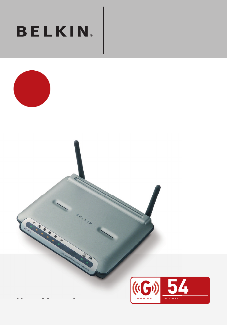
User Manual
ADSL Modem with
Wireless G Router
Designed to Meet ADSL2+ Specification
Page 2

Table of Contents
3
1 Introduction . . . . . . . . . . . . . . . . . . . . . . . . . . . . . . . . . . . . . . . . . . 3
Product Features . . . . . . . . . . . . . . . . . . . . . . . . . . . . . . . . . . . .
Benefits of a Home Network . . . . . . . . . . . . . . . . . . . . . . . . . . .
Advantages of a Belkin Wireless Network
2 Make Sure You Have the Following . . . . . . . . . . . . . . . . . . . . . . .
Package Contents . . . . . . . . . . . . . . . . . . . . . . . . . . . . . . . . . . .
System Requirements . . . . . . . . . . . . . . . . . . . . . . . . . . . . . . . .
Internet Connection Settings
3 Knowing your Router . . . . . . . . . . . . . . . . . . . . . . . . . . . . . . . . . .
4 Connecting your Router . . . . . . . . . . . . . . . . . . . . . . . . . . . . . . . 10
Positioning your Router . . . . . . . . . . . . . . . . . . . . . . . . . . . . . . 10
Connecting your Computers . . . . . . . . . . . . . . . . . . . . . . . . . . 10
Connecting your ADSL Line
Powering up your Router . . . . . . . . . . . . . . . . . . . . . . . . . . . . . 12
Running the Setup Wizard
5 Manually Configuring Your Router . . . . . . . . . . . . . . . . . . . . . .
Understanding the Web-Based User Interface
Changing LAN Settings . . . . . . . . . . . . . . . . . . . . . . . . . . . . . . 19
DHCP Client List
Internet WAN
Wireless . . . . . . . . . . . . . . . . . . . . . . . . . . . . . . . . . . . . . . . . . .
Firewall . . . . . . . . . . . . . . . . . . . . . . . . . . . . . . . . . . . . . . . . . . . 48
Utilities . . . . . . . . . . . . . . . . . . . . . . . . . . . . . . . . . . . . . . . . . . . 57
6 Setting up your Computers . . . . . . . . . . . . . . . . . . . . . . . . . . . . 69
Manually Configuring Network Adapters
Recommended Web Browser Settings
7 Troubleshooting
8 Technical Support Information. . . . . . . . . . . . . . . . . . . . . . . . . . 92
9 Appendixes . . . . . . . . . . . . . . . . . . . . . . . . . . . . . . . . . . . . . . . . . 93
Appendix A: Glossary . . . . . . . . . . . . . . . . . . . . . . . . . . . . . . .
Appendix B: Important Factors for Placement and Setup . . . 98
Appendix C: Internet Connection Setting Table . . . . . . . . . . 102
10 Information . . . . . . . . . . . . . . . . . . . . . . . . . . . . . . . . . . . . . . . 10
. . . . . . . . . . . . . . . . . . . . . . . . . . . . . . . . . . . . 21
. . . . . . . . . . . . . . . . . . . . . . . . . . . . . . . . . . . . . . . 21
. . . . . . . . . . . . . . . . . . . . . . . . . . . . . . . . . . . . . 78
. . . . . . . . . . . . . . . . . . . . . . . . . . . 6
. . . . . . . . . . . . . . . . . . . . . . . . . . . 11
. . . . . . . . . . . . . . . . . . . . . . . . . . . . 13
. . . . . . . . . . . . . . . . . 5
17
. . . . . . . . . . . . 17
28
. . . . . . . . . . . . . . . . . 69
. . . . . . . . . . . . . . . . . . 76
93
3
5
6
6
6
5
4
Page 3

3
Introduction
Thank you for purchasing the Belkin ADSL Modem with Wireless G
Router (the Router). In minutes you will be able to share your Internet
connection and network your computers with your new Router.
The following is a list of features that make your Router an ideal
solution for your home or small office network. Please be sure to read
through this User Manual completely, and pay special attention to
Appendix B entitled “Important Factors for Placement and Setup”.
section
1
2
3
Product Features
Compatibility with Both PCs and Mac® Computers
The Router supports a variety of networking environments including Mac
OS® 8.x, 9.x, X v10.x, AppleTalk®, Linux®, Windows® 95, 98SE, Me, NT®,
2000, and XP, and others. You need an Internet browser and a network
adapter that supports TCP/IP (the standard language of
the Internet).
Front-Panel LED Display
Lighted LEDs on the front of the Router indicate which functions
are in operation. You’ll know at-a-glance whether your Router
is connected to the Internet. This feature eliminates the need
for advanced software and status-monitoring procedures.
Web-Based Advanced User Interface
You can set up the Router’s advanced functions easily through
your web browser, without having to install additional software
onto the computer. There are no disks to install or keep track
of and, best of all, you can make changes and perform setup
functions from any computer on the network quickly and easily.
Integrated 10/100 4-Port Switch
The Router has a built-in, 4-port network switch to allow your wired
computers to share printers, data and MP3 files, digital photos, and much
more. The switch features automatic detection so it will adjust to the speed
of connected devices. The switch will transfer data between computers and
the Internet simultaneously without interrupting or consuming resources.
4
5
6
7
8
9
10
3
Page 4

Introduction
54
Integrated 802.11g Wireless Access Point
802.11g is an exciting new wireless technology that achieves data
rates up to 54Mbps, nearly five times faster than 802.11b.
Built-In Dynamic Host Configuration Protocol (DHCP)
Built-In Dynamic Host Configuration Protocol (DHCP) on-board
makes for the easiest possible connection of a network. The DHCP
server will assign IP addresses to each computer automatically
so there is no need for a complicated networking setup.
NAT IP Address Sharing
Your Router employs Network Address Translation (NAT) to share the single
IP address assigned to you by your Internet Service Provider while saving
the cost of adding additional IP addresses to your Internet service account.
SPI Firewall
Your Router is equipped with a firewall that will protect your network
from a wide array of common hacker attacks including IP Spoofing,
Land Attack, Ping of Death (PoD), Denial of Service (DoS), IP with
zero length, Smurf Attack, TCP Null Scan, SYN flood, UDP flooding,
Tear Drop Attack, ICMP defect, RIP defect, and fragment flooding.
MAC Address Filtering
For added security, you can set up a list of MAC addresses (unique client
identifiers) that are allowed access to your network. Every computer has its
own MAC address. Simply enter these MAC addresses into a list using the
web-based user interface and you can control access to your network.
Universal Plug-and-Play (UPnP) Compatibility
UPnP (Universal Plug-and-Play) is a technology that offers
seamless operation of voice messaging, video messaging,
games, and other applications that are UPnP-compliant.
Support for VPN Pass-Through
If you connect to your office network from home using a VPN
connection, your Router will allow your VPN-equipped computer
to pass through the Router and to your office network.
Page 5

5
Introduction
Benefits of a Home Network
By following our simple setup instructions, you will be able to use your
Belkin home network to:
• Share one high-speed Internet connection with all the computers in
your home
• Share resources, such as files, and hard drives among all the
connected computers in your home
• Share a single printer with the entire family
• Share documents, music, video, and digital pictures
• Store, retrieve, and copy files from one computer to another
• Simultaneously play games online, check Internet email,
and chat
Advantages of a Belkin Wireless Network
Mobility – you’ll no longer need a dedicated “computer room”— now you
can work on a networked laptop or desktop computer anywhere within
your wireless range
Easy installation –
Flexibility – set up and access printers, computers, and other
networking devices from anywhere in your home
Easy Expansion – the wide range of Belkin networking products let
you expand your network to include devices such as printers and
gaming consoles
No cabling required – you can spare the expense and hassle of
retrofitting Ethernet cabling throughout the home or office
Widespread industry acceptance – choose from a wide range of
interoperable networking products
Belkin’s Easy Installation Wizard makes setup simple
section
1
2
3
4
5
6
7
8
9
10
5
Page 6

Make Sure You Have the Following
Package Contents
• ADSL Modem with Wireless G Router
• RJ11 Telephone Cord - Gray
• RJ45 Ethernet Networking Cable — Yellow
• USB 1.0 Cable — Blue
• ADSL Microfilter*
• Power Adapter
• User Manual CD
*ADSL microfilter varies by country. If it’s not
included, you will need to purchase one.
System Requirements
• An active ADSL service with a telephone wall jack for connecting the Router
• At least one computer with a Network Interface Card (NIC) and Internet
browser installed and correctly configured
• TCP/IP networking protocol installed on each computer connected to
the Router
• No other DHCP server on your local network assigning IP addresses to
computers and devices
Internet Connection Settings
Please collect the following information from your Internet Service
Provider (ISP) before setting up the ADSL Modem Wireless G Router.
• Internet connection protocol: _________ (PPPoE, PPPoA, Dynamic IP,
Static IP)
• Multiplexing method or Encapsulation: __________ (LLC or VC MUX)
• Virtual circuit: VPI (Virtual Path Identifier) __________
(a number between 0 and 255)
• VCI (Virtual Channel Identifier) __________
(a number between 1 and 65535)
• For PPPoE and PPPoA users: ADSL account user name _____________
and password _______________
• For static IP users: IP Address ___ . ___ . ___
Subnet Mask ___ . ___ . ___
Default Gateway Server ___ . ___ . ___ .
• IP address for Domain Name Server ___ . ___ . ___ . ___ (If given by
your ISP)
Note: See Appendix C in this User Manual for some common DSL
Internet setting parameters. If you are not sure, please contact your ISP.
Page 7
7
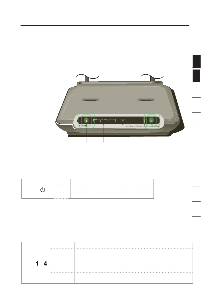
Knowing your Router
7
ADSL LE D
Power LED
LAN St atus LED
(1-4 )
Wireless L AN (WLAN )
Status LED
Inter net LED
The Router has been designed to be placed on a desktop. All of the cables
exit from the rear of the Router for better organization and utility. The LED
indicators are easily visible on the front of the Router to provide you with
information about network activity and status.
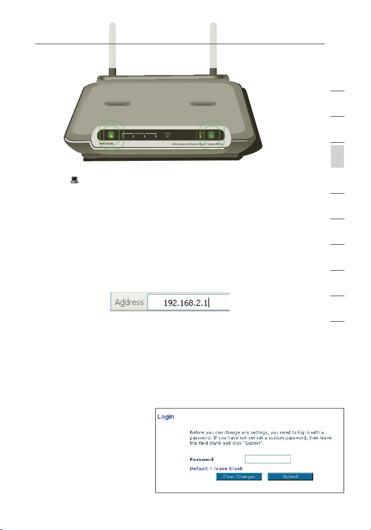
Front Panel
The illustration
shows the front
panel of the
Router:
1. Power LED
When you apply
power to the Router
or restart it, a short period of time elapses while the Router boots up. When
the Router has completely booted up, the Power LED becomes a GREEN light,
indicating the Router is ready for use.
Power
OFF
Green
Red
Power off
Power o
n
Router failed to start
2. LAN Status LEDs
These LAN Status LEDs are labeled 1–4 and correspond to the numbered
ports on the rear of the Router. When a computer is properly connected to
one of the LAN ports on the rear of the Router, the LED will light. Solid GREEN
means a computer or a network-enabled device is connected. When information is being
sent over the port, the LED blinks rapidly. ORANGE indicates a 10Base-T connection.
LAN
—
OFF
No device is connected
Orange
Ethernet link is up and 10Base-T device connected
Orange
blinking
When 10Base-T device transmitting or receiving data
Green
Ethernet link is up and 100Base-T connected
Green
blinking
When 100Base-T device transmitting or receiving data
section
2
1
3
4
5
6
7
8
9
10
11
12
Page 8
Knowing your Router
98
3. WLAN Status LED
The WLAN Status LED is solid GREEN when you enable the wireless LAN
function. It flashes when the Router is transmitting or receiving data wirelessly.
WLAN is off
WLAN is up and connected
WLAN
OFF
Green
Green
blinking
When transmitting or receiving data
4. ADSL LED
The ADSL LED flashes GREEN during negotiation with your ISP. It stays
GREEN when the Router is connected properly to your ADSL service.
No ADSL connection
Negotiating connection
ADSL link is up and connected
ADSL
OFF
Green
blinking
Green
5. Internet LED
The Internet LED shows you when the Router is connected to
the Internet. When the LED is OFF, the Router is NOT connected
to the Internet. When the LED is solid GREEN, the Router
is connected to the Internet. When the LED is blinking, the
Router is transmitting or receiving data from the Internet.
No Internet connection
Connected to the Internet
When transmitting or receiving data
Failed to get IP
Internet
OFF
Green
Green
blinking
Red
Page 9
9
Knowing your Router
Back Panel
The following figure illustrates the rear panel of your Router.
(8)
(7)
(6)
6. DSL Line
This port is for connection to your ADSL line.
Connect your ADSL line to this port.
7. Power Plug
Connect the included 15V DC power supply to this inlet. Using the
wrong type of power adapter may cause damage to your Router.
8. Reset Button
The “Reset” button is used in rare cases when the Router may function
improperly. Resetting the Router will restore the Router’s normal
operation while maintaining the programmed settings. You can also
restore the factory default settings by using the Reset button. Use the
restore option in instances where you may have forgotten your custom
password.
a. Resetting the Router
Push and hold the “Reset” button for one second then release it.
When the “Power/Ready” light becomes solid again, the reset is
complete.
b. Restoring the Factory Defaults
Press and hold the Reset button for five seconds then release it.
When the Power/Ready light becomes solid again, the restore is
complete.
9. Ethernet Ports
The Ethernet ports are RJ45, 10/100 auto-negotiation. The ports are
labeled 1 through 4. These ports correspond to the numbered LEDs on
the front of the Router. Connect your network-enabled computers or
any networking devices to one of these ports.
(9)
1
2
section
3
4
5
6
7
8
9
10
9
Page 10
Connecting your Router
1110
Positioning your Router
Your wireless connection will be stronger the closer your computer is to
your Router. Typical indoor operating range for your wireless devices is
between 100 and 200 feet. In the same way, your wireless connection and
performance will degrade somewhat as the distance between your Router
connected devices increases. This may or may not be noticeable to you.
As you move farther from your Router, connection speed may decrease.
Factors that can weaken signals simply by getting in the way of your
network’s radio waves are metal appliances, or obstructions, and walls.
Please see “Appendix B: Important Factors for Placement and Setup” in this
User Manual for more guidelines.
If you have concerns about your network’s performance that might be
related to range or obstruction factors, try moving the computer to a
position between five and 10 feet from the Router, in order to see if distance
is the problem. If difficulties persist even at close range, please see the
Troubleshooting section for solutions.
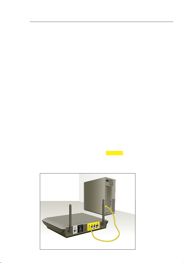
Connecting your Computers
1. Power off your computers and networking equipment.
2. Connect your computer to one of the YELLOW RJ45 ports on the rear
of the Router labeled “connections to your computers” by using an
Ethernet networking cable (one Ethernet network cable is supplied).
Page 11
11
Connecting your Router
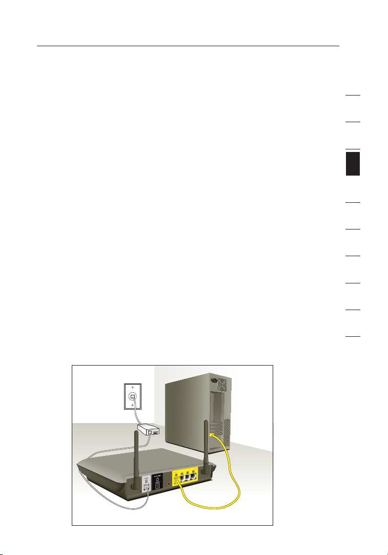
Connecting your ADSL Line
Connection for the Router to the ADSL line varies by country and region.
Typically it involves a microfilter or a microfilter with built-in splitter to allow
simultaneous use of ADSL service and telephone service on the same telephone
line. Please read the following steps carefully and select appropriate method.
1.
If your telephone service and ADSL service are on the same telephone
line, ADSL microfilters are needed for each telephone and device, such as
answering machine, fax machine, and caller ID display. Additional splitters
may be used to separate telephone lines for telephone and the Router.
Note
: Do not connect the ADSL microfilter between the walljack and the
router. This will prevent ADSL service from reaching the modem.
2. If your telephone service and ADSL service are on the same telephone
line and you are using an ADSL microfilter with built-in splitter, connect
the splitter to the telephone wall jack providing ADSL service. Then,
connect the telephone cord from the ADSL microfilter RJ11 port
generally labeled “DSL” to the gray RJ11 port labeled “DSL line” on the
back of your Router. Connect telephony device to the other port on the
ADSL splitter commonly labeled “Phone”. An additional ADSL microfilter
is needed for another telephone and device on the same line.
Note: One RJ11 telephone cord is supplied. When inserting an RJ11
plug, be sure the tab on the plug clicks into position to ensure that it is
properly seated.
1
2
3
section
4
5
6
7
8
9
10
11
Page 12
Connecting your Router
1312
3. If you have a dedicated ADSL service telephone line with an RJ11 wall
jack, simply connect a telephone cord from the wall jack to the gray RJ11
port labeled “DSL line” on the back of your Router.
4. If you have an RJ45 wall jack for your ADSL service, connect an RJ45-
to-RJ11 converter to the wall jack. Then connect one end of a telephone
cord to the converter and the other end to the gray RJ11 port labeled
“DSL line” on the back of your Router.
Note: ADSL microfilter may or may not be
provided depending on your country.
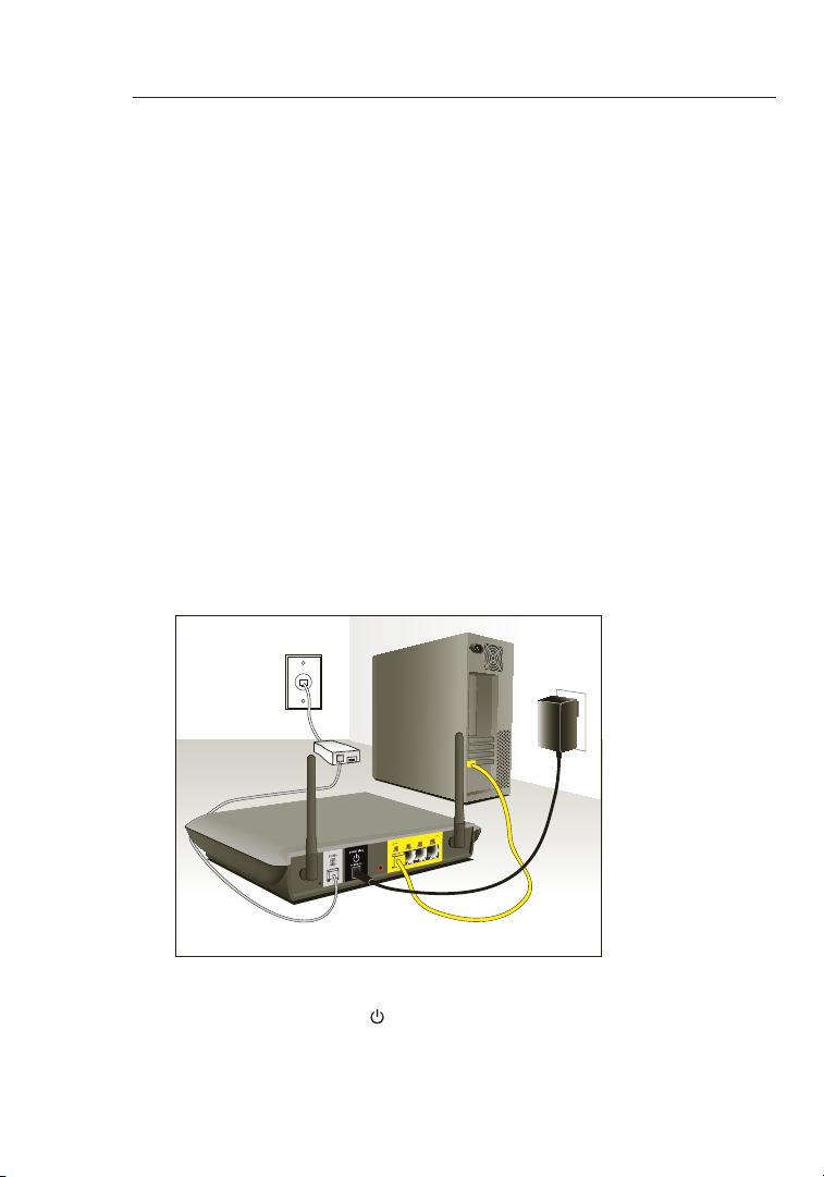
Powering up your Router
1. Connect the supplied power adapter to the Router
power-input plug labeled “Power”.
Note: For safety and performance reasons, only use the supplied power
adapter to prevent damage to the Router.
2. After connecting the power adapter and the power source is turned on,
the Router’s power icon
take a few minutes for the Router to fully start up.
on the front panel should be on. It might
Page 13
13
13
section
2
1
3
4
5
6
7
8
9
10
3. Turn on your computers. After your computers boot up, the LAN status
LED on the front of the Router will be on for each port to which a
wired computer is connected. These lights show you the connection
and activity status. Now you are ready to configure the Router for
ADSL connection.
Running the Setup Wizard
1. You can access the web-based management user interface of the
Router using the Internet browser on a computer connected to the
Router. Type “192.168.2.1” (do not type in anything else such as “http://”
or “www”) in your browser’s address bar. Then press the “Enter” key.
Note: It is strongly recommended that you use a computer
physically connected to the Router with an RJ45 cable for initial setup. Using
a wirelessly connected computer for initial setup is not recommended.
2. The following screen will appear in your browser to prompt you to login. The
Router shi ps with no password entered. In the login screen, leave the password
blank and click the “Submit” button to log in.
Note: It is strongly recommended that you change the password to your own,
for increased security.
Please read the following
section entitled “Manually
configuring your
Router”, for details on
how to change your
password and to reference
other security features.
Connecting your Router
Page 14
Connecting your Router
1514
Connecting your Router
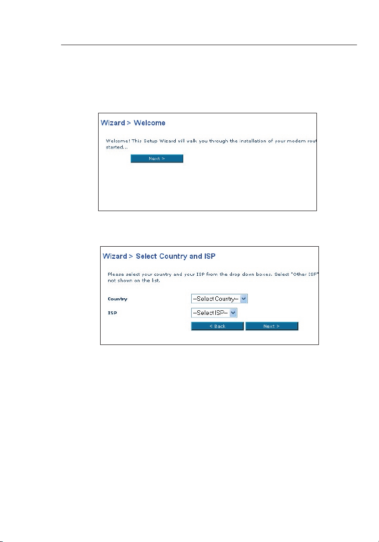
3. The Setup Wizard will start automatically for express
configuration (recommended) Click “Next” to continue.
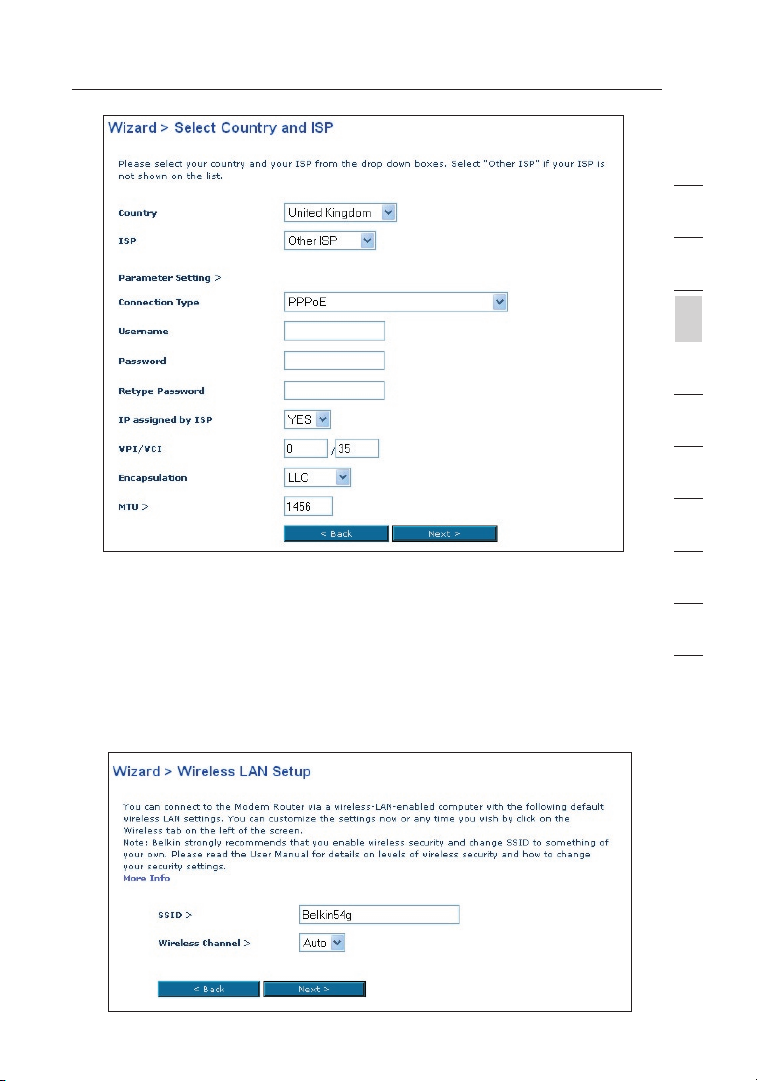
4. The first step is to select your country and ISP, and click “Next”. If your
country and/or ISP is not listed, select “Other Country” or “Other ISP.”
5. Then select your connection type, PPPoE, PPPoA, or other types. For
the “PPPoE” or “PPPoA” you will see the following screen (opposite
page). Enter the required values provided by your ISP and click “Next”.
Note: For more detailed instruction on other connection types, please refer to
the “Manually Configuring your Router” section of this User Manual.
Page 15
15
Connecting your Router
1
2
3
section
4
5
6
7
8
6. Now the Wireless LAN Setup screen will show. You can connect
to the Router via a wireless-LAN-enabled computer with the
following default wireless LAN settings:
SSID = Belkin54g Wireless Channel = Auto Security = off
Note: Belkin strongly recommends that you enable wireless security to
WEP or WPA and change SSID to something of your own. Please read
the User Manual for details on levels of wireless security and how to
change your security settings
15
9
10
Page 16
Connecting your Router
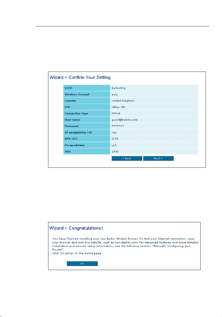
7. Double-check the settings shown on the following screen. You can
click “Back” to change the settings or click “Next” to confirm
Note: You can always restart the Setup Wizard or use the Navigation
Menu on the left to change your setting.
8. Congratulations! You have finished installing your new Belkin
Router. Click “OK” to activate your settings. To test your
Internet connection, open your browser and visit any website,
such as www.belkin.com. For advanced features and more
detailed installation and security setup information, see the
following section, “Manually Configuring your Router”.
Page 17
Manually Configuring your Router
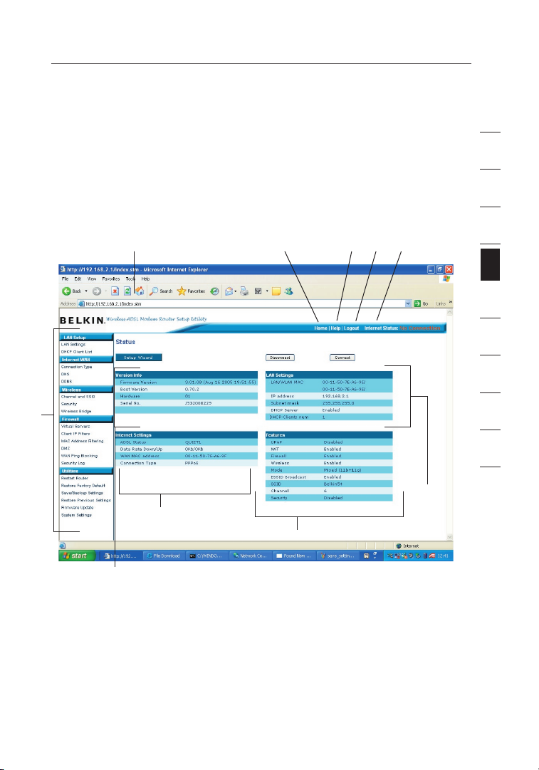
Understanding the Web-Based User Interface
The home page shows you a quick view of the Router’s status and settings. All
advanced setup pages can be reached from this page.
1
. Quick-Navigation Links
You can go directly to any of the Router’s UI pages by clicking directly
on these links. The links are divided into logical categories and grouped
by tabs to make finding a particular setting easier to find. Clicking on the
header of each tab will show you a short description of the tab’s function.
(10)
(1)
(8)
(2) (5)(4)(3)
(7)
1
2
3
4
section
5
6
7
8
9
10
(6)
12
(9)
2. Home Button
The “Home” button is available in every page of the UI. Pressing this
button will take you back to the home page.
3. Help Button
The “Help” button gives you access to the Router’s help pages. Help
is also available on many pages by clicking “more info” next to certain
sections of each page.
1717
Page 18

Manually Configuring your Router
1918
4. Login/Logout Button
This button enables you to log in and out of the Router with the press of
one button. When you are logged into the Router, this button will change
to read “Logout”. Logging into the Router will take you to a separate login
page where you will need to enter a password. When you are logged into
the Router, you can make changes to the settings. When you are finished
making changes, you can log out of the Router by clicking the “Logout”
button. For more information about logging into the Router, see the section
called “Logging into the Router”.
5. Internet Status Indicator
This indicator is visible in all pages of the Router, showing the connection
status of the Router. When the indicator says “connection OK” in GREEN,
the Router is connected to the Internet. When the Router is not connected
to the Internet, the indicator will read “no connection” in RED. The indicator
is automatically updated when you make changes to the settings of the
Router.
6. LAN Settings
Shows you the settings of the Local Area Network (LAN) side of the
Router. Changes can be made to the settings by clicking the “LAN” “Quick
Navigation” link on the left side of the screen.
7. Features
Shows the status of the Router’s UPnP, NAT, and firewall features. Changes
can be made to the settings by clicking on any one of the links or by
clicking the “Quick Navigation” links on the left side of the screen.
8. Internet Settings
Shows the settings of the Internet/WAN side of the Router that connects to
the Internet. Changes to any of these settings can be made by clicking on
the “Internet/WAN” “Quick Navigation” link on the left side of the screen.
9. Version Info
Shows the firmware version, boot-code version, hardware version, and
serial number of the Router.
10. Page Name
The page you are on can be identified by this name. This manual will
sometimes refer to pages by name. For instance, “LAN > LAN Settings”
refers to the “LAN Settings” page.
Page 19
19
Manually Configuring your Router
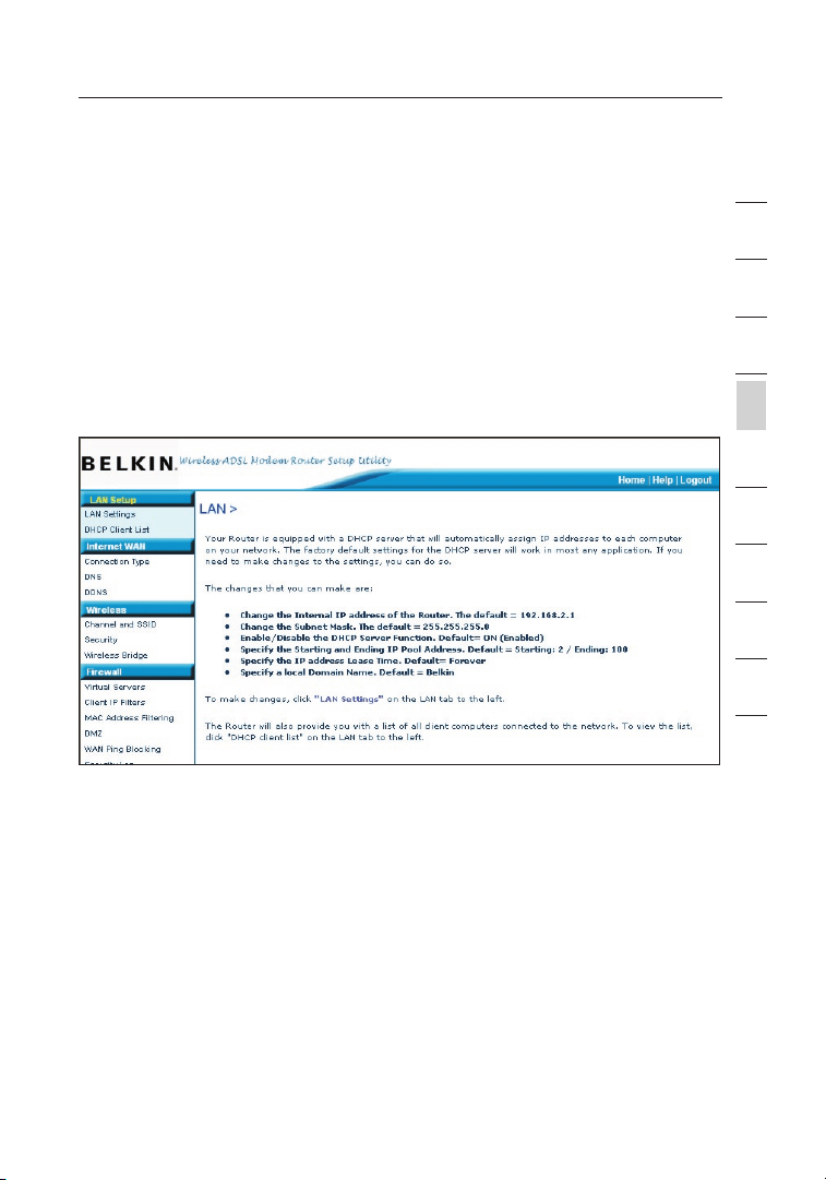
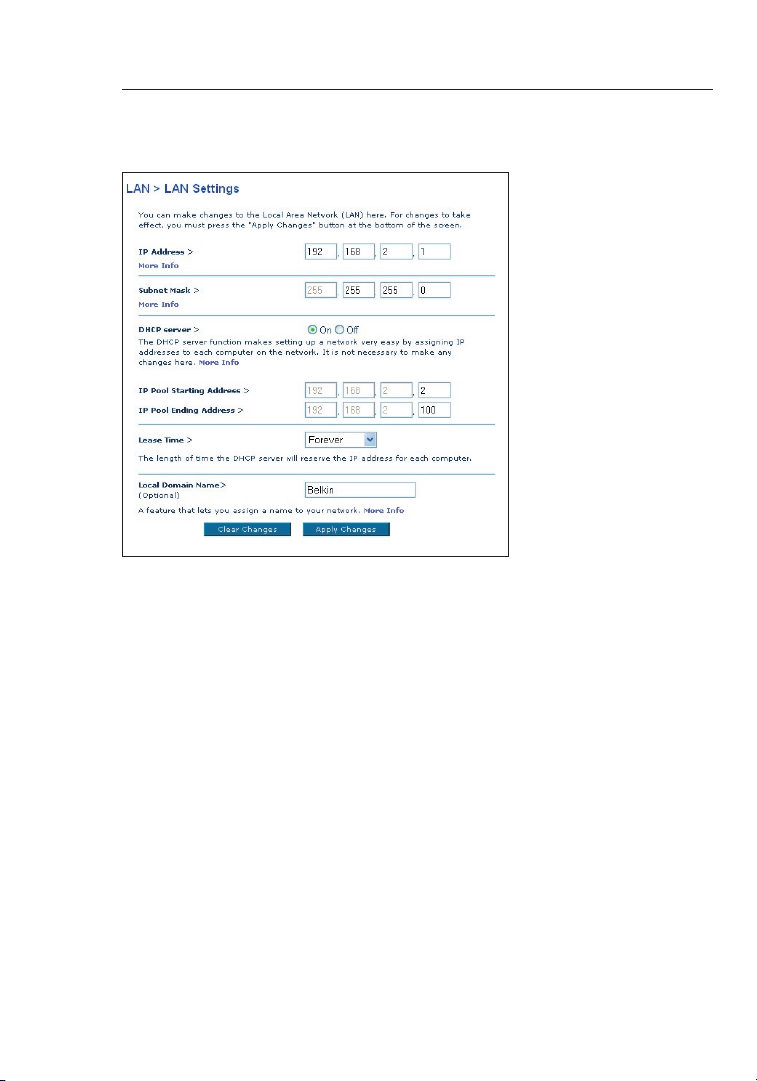
Changing LAN Settings
All settings for the internal LAN setup of the Router can be viewed and
changed here.
LAN Settings
Clicking on the header of the LAN tab (A) will take you to the
LAN tab’s header page. A quick description of the functions can
be found here. To view the settings or make changes to any of
the LAN settings, click on “LAN Settings” (B) or to view the list
of connected computers, click on “DHCP Client List” (C).
1. IP Address
The “IP address” is the internal IP address of the Router. The default
IP address is “192.168.2.1”. To access the setup interface, type this
IP address into the address bar of your browser. This address can
be changed if needed. To change the IP address, type in the new
IP address and click “Apply Changes”. The IP address you choose
should be a non-routable IP. Examples of a non-routable IP are:
192.168.x.x (where x is anything between 0 and 255)
10.x.x.x (where x is anything between 0 and 255)
2. Subnet Mask
There is no need to change the subnet mask. This is a unique,
advanced feature of your Belkin Router.
1
2
3
4
section
5
6
7
8
9
10
19
Page 20
Manually Configuring your Router
2120
3. DHCP Server
The DHCP server function makes setting up a network very easy by
assigning IP addresses to each computer on the network automatically.
The default setting is “On”. The DHCP server can be turned OFF if
necessary, however, in order to do so you must manually set a static IP
address for each computer on your network. To turn off the DHCP server,
select “Off” and click “Apply Changes”.
4. IP Pool
The IP Pool is the range of IP addresses set aside for dynamic assignment
to the computers on your network. The default is 2–100 (99 computers). If
you want to change this number, you can do so by entering a new starting
and ending IP address and clicking on “Apply Changes”. The DHCP server
can assign 100 IP addresses automatically. This means that you cannot
specify an IP address pool larger than 100 computers. For example, starting
at 50 means you have to end at 150 or lower so as not to exceed the 100client limit. The starting IP address must be lower in number than the ending
IP address.
Page 21
21
Manually Configuring your Router
5. Lease Time
Lease time is the length of time the DHCP server will reserve the IP
address for each computer. We recommend that you leave the lease
time set to “Forever”. The default setting is “Forever”, meaning that any
time a computer is assigned an IP address by the DHCP server, the IP
address will not change for that particular computer. Setting lease times
for shorter intervals, such as one day or one hour, frees IP addresses after
the specified period of time. This also means that a particular computer’s
IP address may change over time. If you have set any of the other
advanced features of the Router, such as DMZ or client IP filters, these
are dependent on the IP address. For this reason, you will not want the IP
address to change.
6. Local Domain Name
The default setting is “Belkin”. You can set a local domain name (network
name) for your network. There is no need to change this setting unless
you have a specific advanced need to do so. You can name the network
anything you want such as “MY NETWORK”.
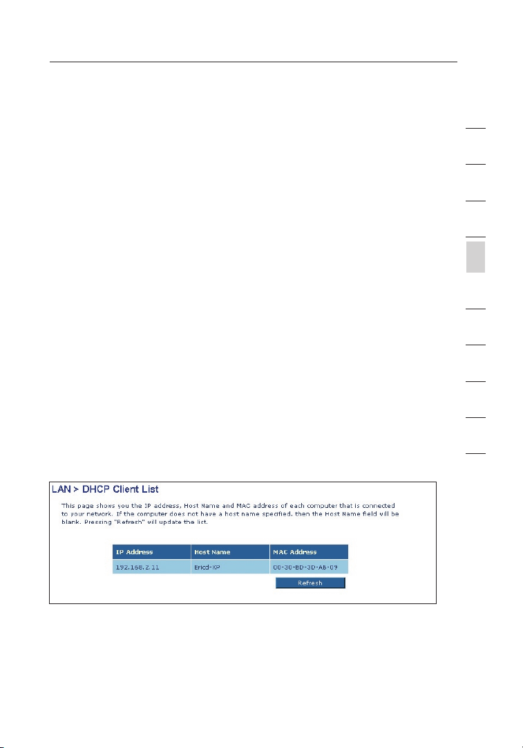
DHCP Client List
You can view a list of the computers (known as clients), which are connected to
your network. You are able to view the IP address (1) of the computer, the host
name (2) (if the computer has been assigned one), and the MAC address (3) of
the computer’s Network Interface Card (NIC). Pressing the “Refresh” (4) button
will update the list. If there have been any changes, the list will be updated.
1
2
3
4
section
5
6
7
8
9
10
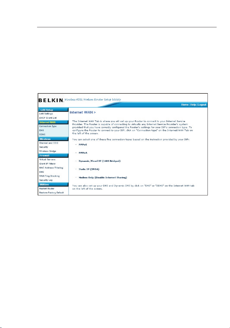
Internet WAN
The “Internet WAN” tab is where you will set up your Router to connect
to your Internet Service Provider. The Router is capable of connecting
to virtually any ADSL Service Provider’s system provided you have
correctly configured the Router’s settings for your ISP’s connection
type. Your connection settings are provided to you by your ISP.
21
Page 22
Manually Configuring your Router
2322
To configure the Router with the settings that your ISP gave you, click
“Connection Type” (1) on the left side of the screen. Select the connection
type you use. If your ISP gave you DNS settings, clicking “DNS” (2) allows
you to enter DNS address entries for ISPs that require specific settings.
When you have finished making settings, the “Internet Status”
indicator will read “Connected” if your Router is set up properly.
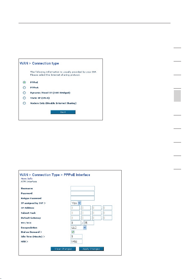
Connection Type
From the “Connection Type” page, you can select one of these five
connection types based on the instruction provided by your ISP:
PPPoE
PPPoA
Dynamic IP (1483 Bridged)
Static IP (IPoA)
Modem Only (Disable Internet Sharing)
Note: See Appendix C in this User Manual for some common DSL
Internet setting parameters. If you are not sure, please contact your ISP.
Page 23
23
Manually Configuring your Router
Select the type of connection you use by clicking the radio button
(1) next to your connection type and then clicking “Next”.
Setting your ISP Connection Type to PPPoE or PPPoA
PPPoE (Point-to-Point Protocol over Ethernet) is the standard method of
connecting networked devices. It requires a user name and password to
access the network of your ISP for connecting to the Internet. PPPoA (PPP
over ATM) is similar to PPPoE, but is mostly implemented in the UK. Select
PPPoE or PPPoA and click “Next”. Then enter the information provided
by your ISP, and click “Apply Changes” to activate your settings.
1
2
3
4
section
5
6
7
8
9
10
23
Page 24
Manually Configuring your Router
2524
1. User Name - Enter the user name. (Assigned by your ISP).
2. Password - Enter your password. (Assigned by your ISP).
3. Retype Password - Confirm the password.
(Assigned by your ISP).
4. IP Assigned by ISP – Leave “Yes” if your ISP automatically
assigns IP address. If your ISP assigned a fixed IP address,
select “No” and enter assigned values.
5. VPI/VCI - Enter your Virtual Path Identifier (VPI) and Virtual
Circuit Identifier (VCI) parameter here. (Assigned by your ISP).
6. Encapsulation - Select your encapsulation type (supplied by
your ISP) to specify how to handle multiple protocols at the
ATM transport layer. VC-MUX: PPPoA Virtual Circuit Multiplexer
(null encapsulation) allows only one protocol running per virtual
circuit with fewer overheads. LLC: PPPoA Logical Link Control
allows multiple protocols running over one virtual circuit (more
overhead).
7. Dial on Demand - By selecting “Dial on Demand” your Router
will automatically connect to the Internet when a user opens up a
web browser.
8. Idle Time (Minutes) - Enter the maximum idle time for the
Internet connection. After this time has been exceeded, the
connection will be terminated.
9. MTU - The MTU setting should never be changed unless your you
a specific MTU setting. Making changes to the MTU can cause
problems with your Inter net connection including disconnection
from the Internet, slow Internet access and problems with
Internet applications working properly.
Page 25
25
Manually Configuring your Router
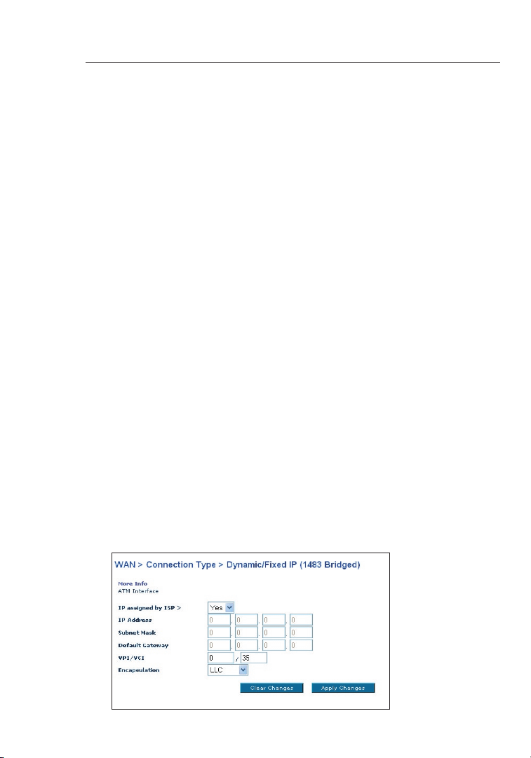
Setting your Connection Type to Dynamic IP (1483 Bridged)
This connection method bridges your network and ISP’s network together.
The Router will obtain IP address automatically from your ISP’s DHCP server.
1)
2)
3)
1. IP Assigned by ISP – Leave “Yes” if your ISP automatically
assigns IP address. If your ISP assigned a fixed IP address,
select “No” and enter assigned values.
2. VPI/VCI - Enter your Virtual Path Identifier (VPI) and Virtual
Circuit Identifier (VCI) parameter here. These identifiers are
assigned by your ISP.
3. Encapsulation - Select LLC or VC MUX your ISP uses.
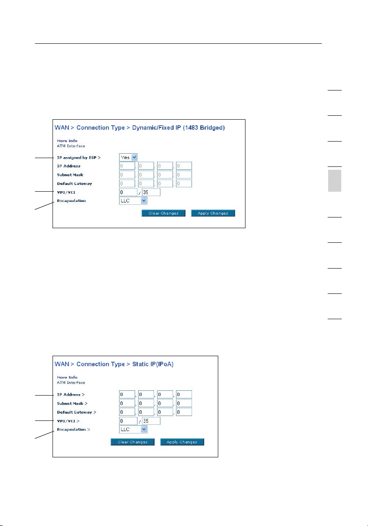
Setting your ISP Connection Type to Static IP (IPoA)
This connection type is also called “Classical IP over ATM” or “CLIP”, which
your ISP provides a fixed IP for your Router to connect to the Internet.
1
2
3
4
section
5
6
7
8
9
10
1)
2)
3)
1. IP Address – Enter an IP address assigned by your ISP for the
Router WAN interface.
25
Page 26
Manually Configuring your Router
2726
2. Subnet Mask - Enter a subnet mask assigned by your ISP.
3. Default Route -
Enter a default gateway IP address. If the Router cannot find the
destination address within its local network, it will forward the
packets to the default gateway assigned by your ISP.
4. VPI/VCI - Enter your Virtual Path Identifier (VPI) and Virtual
Circuit Identifier
(VCI) parameter here. These identifiers are assigned by your ISP.
5. Encapsulation - Select LLC or VC MUX your ISP uses.
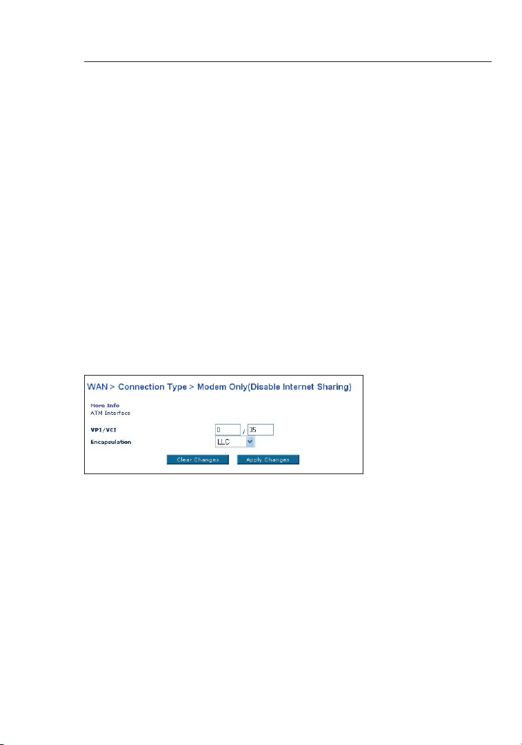
Setting your Connection Type to Modem
Only (Disable Internet Sharing)
In this mode, the Router simply acts as a bridge passing packets across
the DSL port. It requires additional software to be installed on your
computers in order to access the Internet.
1. VPI/VCI - Enter your Virtual Path Identifier (VPI) and Virtual
Circuit Identifier (VCI) parameter here. (Assigned by your ISP).
2. Encapsulation - Select LLC or VC MUX. (Assigned by your ISP).
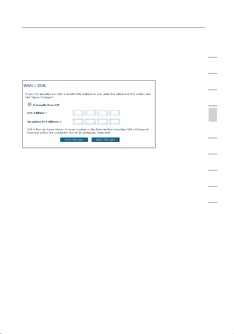
DNS (Domain Name Server) Settings
A “Domain Name Server” is a server located on the Internet that translates
Universal Resource Links (URLs) like “www.belkin.com” to IP addresses.
Many ISPs do not require you to enter this information into the Router. The
“Automatic from ISP” box (1) should be checked if your ISP did not give
you a specific DNS address. If you are using a static IP connection type,
then you may need to enter a specific DNS address and secondary DNS
address for your connection to work properly. If your connection type is
dynamic or PPPoE, it is likely that you do not have to enter a DNS address.
Page 27
27
Manually Configuring your Router
Leave the “Automatic from ISP” box checked. To enter the DNS address
settings, uncheck the “Automatic from ISP” box and enter your DNS entries
in the spaces provided. Click “Apply Changes” (2) to save the settings.
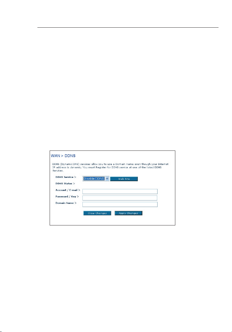
Using DDNS (Dynamic DNS)
The DDNS service allows you to alias a dynamic IP address to a static host
name in any of the many domains DynDNS.org offers, allowing your network
computers to be more easily accessed from various locations on the
Internet. DynDNS.org provides this service, for up to five host names, free
to the Internet community. TZO.com is another alternative to DynDNS.org.
DDNS service is ideal for a home website, file server, or to make
it easy to access your home PC and stored files while you’re at
work. Using the service can ensure that your host name always
points to your IP address, no matter how often your ISP changes
it. When your IP address changes, your friends and associates can
always locate you by visiting yourname.dyndns.org instead!
1
2
3
4
section
5
6
7
8
9
10
To register free for your Dynamic DNS host name,
please visit http://www.dyndns.org
.
27
Page 28
Manually Configuring your Router
2928
Setting up the Router’s Dynamic DNS Update Client
You must register with DynDNS.org’s free update service before using this
feature. Once you have your registration, follow the directions below.
1. Enter your DynDNS.org user name in the “Account / E-mail” field (1).
2. Enter your DynDNS.org password in the “Password / Key” field (2).
3. Enter the DynDNS.org domain name you set up with DynDNS.org in
the “Domain Name” field (3).
4. Click “Apply Changes” to update your IP address.
Whenever your IP address assigned by your ISP changes, the Router will
automatically update DynDNS.org’s servers with your new IP address. You
can also do this manually by clicking the “Apply Changes” button (4).
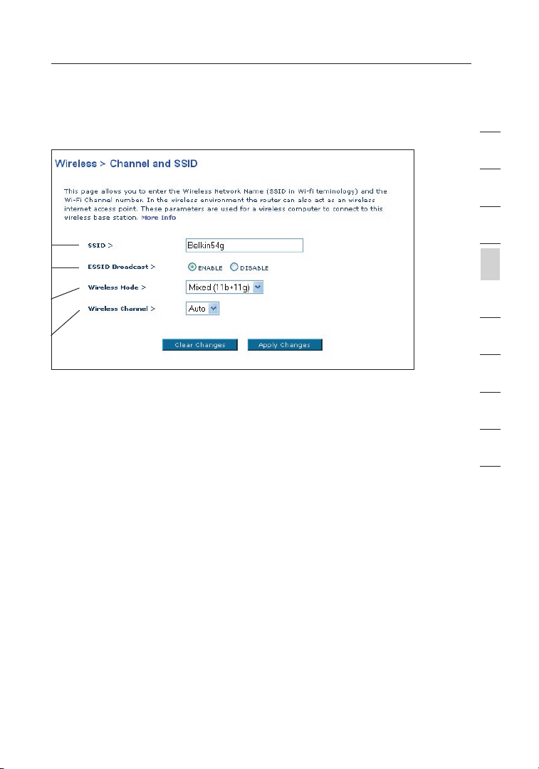
Wireless
The “Wireless” tab lets you make changes to the wireless network
settings. From this tab, you can make changes to the wireless network
name (SSID), operating channel, and encryption security settings.
Page 29
29
Manually Configuring your Router
Channel and SSID
1)
2)
3)
4)
1. Changing the Wireless Network Name (SSID)
To identify your wireless network, a name called the SSID (Service Set
Identifier) is used. The default SSID of the Router is “belkin54g”. You
can change this to anything you want to or you can leave it unchanged.
If there are other wireless networks operating in your area, you will want
to make sure that your SSID is unique (does not match that of another
wireless network in the area). To change the SSID, type in the SSID
that you want to use in the SSID field (1) and click “Apply Changes”
(2). The change is immediate. If you make a change to the SSID, your
wireless-equipped computers may also need to be reconfigured to
connect to your new network name. Refer to the documentation of your
wireless network adapter for information on making this change.
2. Using the ESSID Broadcast Feature
For security purposes, you can choose not to broadcast your
network’s SSID. Doing so will keep your network name hidden from
computers that are scanning for the presence of wireless networks.
To turn off the broadcast of the SSID, select “DISABLE” and then
click “Apply Changes”. The change is immediate. Each computer
now needs to be set to connect to your specific SSID; an SSID of
“ANY” will no longer be accepted. Refer to the documentation of your
wireless network adapter for information on making this change.
Note: This advanced feature should be employed by advanced users only.
1
2
3
4
section
5
6
7
8
9
10
29
Page 30

Manually Configuring your Router
3130
3. Using the Wireless Mode Switch
Your Router can operate in three different wireless
modes: “Mixed (11b+11g)”, “11g Only”, and “11b Only”.
The different modes are explained below.
“Mixed (11b+11g)” Mode —In this mode, the Router is compatible
with 802.11b and 802.11g wireless clients simultaneously. This
is the factory default mode and ensures successful operation
with all Wi-Fi-compatible devices. If you have a mix of 802.11b
and 802.11g clients in your network, we recommend leave the
setting as defaultThis setting should only be changed if you have
a specific reason to do so.
”11g –Only” Mode—802.11g-Only mode works with 802.11g clients
only. This mode is recommended only if you want to prevent
802.11b clients from accessing your network. To switch modes,
select the desired mode from the “Wireless Mode” drop-down
box. Then, click “Apply Changes”.
”11b Only” Mode—We recommend you DO NOT use this mode unless
you have a very specific reason to do so. This mode exists only
to solve unique problems that may occur with some 802.11b
client adapters and is NOT necessary for interoperability of
802.11g and 802.11b standards.
4. Changing the Wireless Channel
There are a number of operating channels you can choose from. In the
United States, there are 11 channels. In the United Kingdom and most of
Europe, there are 13 channels. In a small number of other countries, there
are other channel requirements. Your Router is configured to operate on the
proper channels for the country you reside in. The default is “Auto”.
The channel can be changed if needed. If there are other wireless networks
operating in your area, your network should be set to operate on a channel
that is different than the other wireless networks. For best performance,
use a channel that is at least five channels away from the other wireless
network. For instance, if another network is operating on channel 11, then
set your network to channel 6 or below. To change the channel, select the
channel from the drop-down list. Click “Apply Changes”. The change is
immediate.
Page 31

31
Manually Configuring your Router
Encryption/Security
Securing your Wi-Fi Network
Here are a few different ways you can maximize the security of your wireless
network and protect your data from prying eyes and ears. This section is
intended for the home, home office, and small office user. At the time of this
User Manual’s publication, there are three encryption methods available.
Name 64-bit Wired
Acronym 64-bit WEP 128-bit WEP WPA-TKIP WPA-AES
Security Good Better Best Best
Features Static keys Static keys Dynamic key
Equivalent
Privacy
Encryption
keys based
on RC4
algorithm
(typically
40-bit keys)
128-bit Wired
Equivalent
Privacy
More secure
than 64-bit
WEP using a
key length of
104 bits plus
24 additional
bits of system
generated
data.
Wi-Fi Protected
Access-TKIP
encryption
and mutual
authentication.
TKIP (temporal
key integrity
protocol)
added so
that keys are
rotated and
encryption is
strengthened.
WEP (Wired Equivalent Privacy)
WEP is a common protocol that adds security to all Wi-Fi-compliant
wireless products. WEP was designed to give wireless networks the
equivalent level of privacy protection as a comparable wired network.
Wi-Fi Protected
Access-AES
Dynamic key
encryption
and mutual
authentication.
AES (Advanced
Encryption
Standard) does
not cause any
throughput
loss.
1
2
3
4
section
5
6
7
8
9
10
64-Bit WEP
64-bit WEP was first introduced with 64-bit encryption, which includes
a key length of 40 bits plus 24 additional bits of system-generated
data (64 bits total). Some hardware manufacturers refer to 64-bit
as 40-bit encryption. Shortly after the technology was introduced,
researchers found that 64-bit encryption was too easy to decode.
31
Page 32

Manually Configuring your Router
3332
128-Bit WEP
As a result of 64-bit WEP’s potential security weaknesses, a more secure
method of 128-bit encryption was developed. 128-bit encryption includes a key
length of 104 bits plus 24 additional bits of system-generated data (128 bits
total). Some hardware manufacturers refer to 128-bit as 104-bit encryption.
Most of the new wireless equipment in the market today supports
both 64-bit and 128-bit WEP encryption, but you might have
older equipment that only supports 64-bit WEP. All Belkin wireless
products will support both 64-bit and 128-bit WEP
Encryption Keys
After selecting either the “64-bit” or “128-bit WEP” encryption mode, it is
critical that you generate an encryption key. If the encryption key is not
consistent throughout the entire wireless network, your wireless networking
devices will be unable to communicate with one another on your network
and you will not be able to successfully communicate within your network.
You can enter your key by typing in the hex key manually, or you can
type in a passphrase in the “Passphrase” field and click “Generate”
to create a key. A hex (hexadecimal) key is a mixture of numbers
and letters from A–F and 0–9. For 64-bit WEP, you need to enter
10 hex keys. For 128-bit WEP, you need to enter 26 hex keys.
For instance:
AF 0F 4B C3 D4 = 64-bit WEP key
C3 03 0F AF 0F 4B B2 C3 D4 4B C3 D4 E7 = 128-bit WEP key
The WEP passphrase is NOT the same as a WEP key. Your wireless card
uses this passphrase to generate your WEP keys, but different hardware
manufacturers might have different methods for generating the keys. If
you have equipment from multiple vendors in your network, you can use
the hex WEP key from your Router or access point and enter it manually
into the hex WEP key table in your wireless card’s configuration screen.
WPA (Wi-Fi Protected Access)
WPA (Wi-Fi Protected Access) is a new Wi-Fi standard that was designed to
improve upon the security features of WEP. To use WPA security, the drivers and
software of your wireless equipment must be upgraded to support WPA. These
updates will be found on the wireless vendors’ websites. There are two types
of WPA security: WPA-PSK (no server) and WPA (with 802.1x radius server).
Page 33

33
Manually Configuring your Router
WPA-PSK (no server)
This method uses what is known as a Pre-Shared key as the Network
key. A Network key is basically a password that is between eight and
63 characters long. It can be a combination of letters, numbers, or
characters. Each client uses the same Network key to access the network.
Typically, this is the mode that will be used in a home environment.
WPA (with 802.1x radius server)
With this system, a radius server distributes the Network key to the
clients automatically. This is typically found in a business environment.
WPA2
The Router features WPA2, which is the second generation of WPA based
802.11i standard. It offers higher level of wireless security by combining
advanced network authentication and stronger AES encryption method.
WPA2 Requirements
IMPORTANT: In order to use WPA2 security, all your computers and
wireless client adapters must be upgraded with patches, driver, and client
utility software that supported WPA2. At the time of this User Manual’s
publication, a couple security patches are available, for free download,
from Microsoft. These patches work only with the Windows XP operating
system. Other operating systems are not supported at this time.
For Windows XP computer that does not have Service Pack 2 (SP2), a file
from Microsoft called “Windows XP Support Patch for Wireless Protected
Access (KB 826942)” is available for free download at http://support.
microsoft.com/?kbid=826942
For Windows XP with Service Pack 2, Microsoft has released a free
download to update the wireless client components to support WPA2
(KB893357). The update can be download from: http://support.microsoft.
com/default.aspx?scid=kb;en-us;893357
IMPORTANT: You also need to ensure that all your wireless client cards /
adapters support WPA2, and that you have downloaded and installed the
latest driver. Most of the Belkin Wireless cards have update driver available
for download from the Belkin support site: www.belkin.com/networking.
For a list of Belkin wireless products that support WPA/WPA2,
please visit our website at www.belkin.com/networking
.
1
2
3
4
section
5
6
7
8
9
10
33
Page 34

Manually Configuring your Router
3534
Sharing the Same Network Keys
Most Wi-Fi products ship with security turned off. So once you have
your network working, you need to activate WEP or WPA and make sure
your wireless networking devices are sharing the same Network key.
Wi rele ss
Rou ter
Net work key =
MyPassword
Net work key =
MyPassword
Net work key =
MyPassword
Net work key =
WRONG Password
Wi rele ss G N oteb ook
Net wor k Car d
Wi rele ss G D esk top
Net wor k Car d
Wi rele ss G U SB
Net wor k Ada pter
AF
0F4BC3
D4
Example
64-bit key
128-bit key
Using a Hexadecimal Key
A hexadecimal key is a mixture of numbers and letters from A–F and 0–9. 64-bit
keys are five two-digit numbers. 128-bit keys are 13 two-digit numbers.
For instance:
AF 0F 4B C3 D4 = 64-bit key
C3 03 0F AF 0F 4B B2 C3 D4 4B C3 D4 E7 = 128-bit key
In the boxes below, make up your key by writing in two characters
between A–F and 0–9 in each box. You will use this key to program the
encryption settings on your Router and your wireless computers.
The Wireless G
Desktop Network
Card cannot access
the network because
it is using a different Network key than the Network key
that is configured on the Wireless G Router.
Page 35

35
Manually Configuring your Router
Note to Mac users: Original Apple AirPort® products support 64-bit
encryption only. Apple AirPort 2 products can support 64-bit or 128-bit
encryption. Please check your product to see which version you are using.
If you cannot configure your network with 128-bit encryption, try 64-bit
encryption.
WEP Setup
1. Select “WEP” from the drop-down menu.
2. Select “WEP Mode” of 64-bit or 128-bit
3. After selecting your “WEP mode”, you can enter your key by typing in
the hex key manually.
A hex (hexadecimal) key is a mixture of numbers and letters from A–F and
0–9. For 64-bit WEP, you need to enter 10 hex keys. For 128-bit WEP, you
need to enter 26 hex keys.
For instance:
AF 0F 4B C3 D4 = 64-bit key
C3 03 0F AF 0F 4B B2 C3 D4 4B C3 D4 E7 = 128-bit key
1
2
3
4
section
5
6
7
8
9
10
35
Page 36

Manually Configuring your Router
3736
3. Click “Apply Changes” to finish. Encryption in the Router is now
set. Each of your computers on your wireless network will now need
to be configured with the same security settings.
WARNING: If you are configuring the Wireless Router or access point
from a computer with a wireless client, you will need to ensure that
security is turned ON for this wireless client. If this is not done, you will
lose your wireless connection.
Changing the Wireless Security Settings
Your Router is equipped with WPA/WPA2 (Wi-Fi Protected Access), the latest
wireless security standard. It also supports the legacy security standard, WEP
(Wired Equivalent Privacy). By default, wireless security is disabled. To enable
security, you must first determine which standard you want to use. To access
the security settings, click “Security” on the Wireless tab.
WPA Setup
Note: To use WPA security, all your clients must be upgraded to drivers
and software that support it. At the time of this User Manual’s publication, a
security patch download is available free from Microsoft. This patch works
only with the Windows XP operating system. You also need to download the
latest driver for your Belkin Wireless G Desktop or Notebook Network Card
from the Belkin support site. Other operating systems are not supported at
this time. Microsoft’s patch only supports devices with WPA-enabled drivers
such as Belkin 802.11g products.
There are two types of WPA security: WPA-PSK (no server) and WPA
(with radius server). WPA-PSK (no server) uses a so-called Pre-Shared
key as the security key. A Pre-Shared key is a password that is between
eight and 63 characters long. It can be a combination of letters, numbers,
and other characters. Each client uses the same key to access the
network. Typically, this mode will be used in a home environment.
WPA (with radius server) is a configuration wherein a radius
server distributes the keys to the clients automatically.
This is typically use d in a business environment.
WPA2 is the second generation of WPA, offering a more
advanced encryption technique over WPA.
Page 37

37
Manually Configuring your Router
Setting WPA/WPA2-PSK (no server)
1. From the “Allowed Client Type” drop-down menu, select “WPA/
WPA2”.
2. For Authentication, select “Pre-shared Key” for typical home/SOHO
use. This setting will have to be identical on the clients that you set
up.
3. Enter your Pre-Shared key. This can be from eight to 63 characters
and can be letters, numbers, or symbols. This same key must be
used on all of the clients that you set up. For example, your PSK
might be something like: “Smith family network key”.
4. Click “Apply Changes” to finish. You must now set all clients to
match these settings.
Setting WPA/WPA2 (with radius server) Settings
If your network uses a radius server to distribute
keys to the clients, use this setting.
1. From the “Allowed Client Type” drop-down menu, select “WPA/
WPA2”.
2. For Encryption Technique, select “802.1x” for environment with
RADIUS server. This setting will have to be identical on the clients
that you set up.
3. Enter the session idle timeout of the radius server into the “Session
Idel Timeout” field.
4. Enter the key interval, how often the keys are distributed (in
packets), in the “Re-Authentication Period” field.
1
2
3
4
section
5
6
7
8
9
10
37
Page 38

Manually Configuring your Router
3938
5. Enter the waiting time after authentication failed in the “Quiet Period”
filed.
6. Enter the IP address and port number of the radius server into the
“Server-IP” and “Server-Port” fields.
7. Enter the radius key into the “Secret Key” field.
8. Click “Apply Changes” to finish. You must now set all clients to
match these settings.
1)
2)
3)
4)
5)
6)
7)
8)
Note: Make sure your wireless computers are updated to work with WPA2
and have the correct settings to get proper connection to the Router.
Configuring your Belkin Wireless G
Network Cards to Use Security
Please Note: This section provides information on how to configure
your Belkin Wireless G Network Cards to use security.
At this point, you should already have your Wireless Router or access point set
to use WPA or WEP. In order for you to gain a wireless connection, you will need
to set your wireless notebook card and wireless desktop card to use the same
security settings.
Page 39

39
Manually Configuring your Router
Connecting your Computer to a Wireless Network that
Requires a 64-Bit or 128-Bit WEP Key
1. Double-click the “Signal Indicator” icon to bring up the “Wireless
Network” screen. The “Advanced” button will allow you to view and
configure more options of your wireless card.
2. Under the “Wireless Network Properties” tab, select a network name
from the “Available networks” list and click “Configure”.
3. Under “Data Encryption” select “WEP”.
4. Ensure the check box “Network key is provided for me automatically”
at the bottom is unchecked. If you are using this computer to
connect to a corporate network, please consult your network
administrator if this box needs to be checked.
5. Type your WEP key in the “Network key” box.
1
2
3
4
section
5
6
7
8
9
10
Important: A WEP key is a mixture of numbers and letters from A–F and
0–9. For 128-bit WEP, you need to enter 26 keys. For 64-bit WEP, you need
to enter 10 keys. This Network key needs to match the key you assign to
your Wireless Router or access point.
6. Click “OK” to save the settings.
39
Page 40

Manually Configuring your Router
4140
Connecting your Computer to a Wireless Network that
Requires WPA-PSK (no server)
1. Double-click the “Signal Indicator” icon to bring up the “Wireless
Network” screen. The “Advanced” button will allow you to view and
configure more options of your wireless card.
2. Under the “Wireless Networks” tab, select a network name from the
“Available networks” list and click “Configure”.
3. Under “Network Authentication” select “WPA-PSK (No Server)”.
4. Type your WPA key in the “Network key” box.
Important: WPA-PSK is a mixture of numbers and letters from A–Z and
0–9. For WPA-PSK you can enter eight to 63 keys. This Network key needs
to match the key you assign to your Wireless Router or access point.
5. Click “OK” to save the settings.
Page 41

41
Manually Configuring your Router
Connecting your Computer to a Wireless Network that
Requires WPA (with radius server)
1. Double-click the “Signal Indicator” icon to bring up the “Wireless
Network” screen. The “Advanced” button will allow you to view
and configure more options of your wireless card.
2. Under the “Wireless Networks” tab, select a network name from
the “Available networks” list and click “Configure”.
3. Under “Network Authentication” select WPA.
4. Under the “Authentication” tab, select the settings that are
indicated by your network administrator.
1
2
3
4
section
5
6
7
8
9
10
5. Click “OK” to save the settings.
41
Page 42

Manually Configuring your Router
4342
Setting Up WPA for a Non-Belkin Wireless Desktop and
Wireless Notebook Cards
For non-Belkin WPA Wireless Desktop and Wireless Notebook
Cards that are not equipped with WPA-enabled software, a file
from Microsoft called “Windows XP Support Patch for Wireless
Protected Access” is available as a free download.
Please Note: The file that Microsoft has made available works only with
Windows XP. Other operating systems are not supported at this time.
Important: You also need to ensure that the wireless card manufacturer
supports WPA and that you have downloaded and installed the latest
driver from their support site.
Supported Operating Systems:
• Windows XP Professional
• Windows XP Home Edition
Page 43

43
Manually Configuring your Router
Setting Up Windows XP Wireless
Network Utility to Use WPA-PSK
In order to use WPA-PSK, ensure you are using Windows
Wireless Network Utility by doing the following:
1. Under Windows XP, click “Start > Control Panel > Network
Connections”.
2. Right-click on “Wireless Network Connection”, and select
“Properties”.
3. Clicking on the “Wireless Networks” tab will display the following
screen. Ensure the “Use Windows to configure my wireless network
settings” check box is checked.
4. Under the “Wireless
Networks” tab, click the
“Configure” button, and you
will see the following screen.
1
2
3
4
section
5
6
7
8
9
10
5. For a home or small business user,
select “WPA-PSK” under “Network
Authentication”.
Note: Select “WPA” if you are using
this computer to connect to a corporate
network that supports an authentication server such as a radius server.
Please consult your network administrator for further information.
43
Page 44

Manually Configuring your Router
4544
Main Router
Secondary AP
Inter net
6. Select “TKIP” or “AES” under “Data Encryption”. This setting will
have to be identical to the Router that you set up.
7. Type in your encryption key in the “Network Key” box.
Important: Enter your Pre-Shared key. This can be from eight to 63
characters and can be letters, numbers, or symbols. This same key
must be used on all of the clients that you set up.
8. Click “OK” to apply settings.
Wireless Range Extension and Bridging
What is a Wireless Bridge?
A wireless bridge is actually an operation “mode” you can use to extend
the range of your wireless network, or add an extension of your network
in another area of your office or home without running cables.
Note: We can make no guarantees that this feature will interoperate
with hardware from other wireless mavnufacturers.
Note: Please make sure to download the latest firmware version for
the Router or Access Point for optimal performance at: http://web.
belkin.com/support
Wi rele ss Br idge Link
Wi red C ompu ter Wi rele ss Co mput er Wi rele ss Co mput er
Wi rele ss Co mput er
Wi rele ss Co mput er
Page 45

45
Manually Configuring your Router
Main Router
Secondary AP
Inter net
Adding Another Network Segment Wirelessly
Connecting a network switch or hub to the Access Point’s
RJ45 jack will allow a number of computers connected
to the switch access to the rest of the network.
Wi rele ss Br idge Link
Network Switc h
Wi red C ompu ter Wi rele ss Co mput er
Wi red C ompu ters
1
2
3
4
section
5
6
7
8
9
10
45
Page 46

Manually Configuring your Router
4746
FCC ID: K7SF5D7130A
model # F5D7131
Wireless
Range Extender/
Access Point
IC: 3623A-F5D7130A
Complies with Canada RSS-210
P81807
F5D7131
WLAN MAC Address
Serial #
LAN MAC Address
Setting up a Bridge Between your Router
and a Secondary Access Point
Bridging your Belkin Router to a secondary Access Point requires that you
access the Router’s Advanced Setup Utility and enter the MAC address of the
Access Point in the appropriate area. There are also a few other requirements.
PLEASE BE SURE TO FOLLOW THE STEPS BELOW CAREFULLY.
1. Set your Access Point to the same channel as the Router. For
more information on changing channels, see “Wireless - Channel
and SSID” section of this User Manual.
2. Find the Access Point’s MAC address on the bottom of the
Access Point. There are two MAC addresses on the bottom label.
You will need the MAC address named “WLAN MAC Address”.
The MAC address starts with 0030BD and is followed by six other
numbers or letters (i.e. 0030BD-XXXXXX). Write the MAC address
below. Go to the next step.
3. Place your secondary Access Point within range of your Wireless
Router and near the area where you want to extend the range
or add the network segment. Typically, indoor range should be
between 100 and 200 feet.
4. Connect power to your Access Point. Make sure the Access Point
is on and proceed to the next step.
5. From a computer already connected to your Router, access the
Advanced Setup Utility by opening your browser. In the address
bar, type in “192.168.2.1”. Do not type in “www” or “http://”
before the number. Note: If you have changed your Router’s IP
address, use that IP address.
6. You will see the Router’s user interface in the browser window.
Click “Wireless Bridge” (2) on the left-hand side of the screen.
You will see the following screen.
Page 47

47
Manually Configuring your Router
1
2
3
4
section
5
6
7
8
9
10
7. Check the box that says “Enable ONLY specific Access Points to
connect” (1).
8. In the field named “AP1” (3), type in the MAC address of your
secondary Access Point. When you have typed in the address,
click “Apply Changes”.
9. Bridging is now set up.
Note: It may take up to a minute for the bridged connection to
properly establish itself. In some cases it may be necessary to restart
the access point and the router to initiate the bridge.
47
Page 48

Manually Configuring your Router
4948
Firewall
Your Router is equipped with a firewall that will protect your network from a
wide array of common hacker attacks including:
• IP Spoofing
• Land Attack
• Ping of Death (PoD)
• Denial of Service (DoS)
• IP with zero length
• Smurf Attack
• TCP Null Scan
• SYN flood
• UDP flooding
• Tear Drop Attack
• ICMP defect
• RIP defect
• Fragment flooding
The firewall also masks common ports that are frequently used to
attack networks. These ports appear to be “Stealth”, meaning that
essentially they do not exist to a would-be hacker. You can turn
the firewall function off if needed; however, it is recommended that
you leave the firewall enabled. Disabling the firewall protection will
not leave your network completely vulnerable to hacker attacks,
but it is recommended that you leave the firewall enabled.
Page 49

49
Manually Configuring your Router
Virtual Servers
Virtual servers allow you to route external (Internet) calls for services such
as a web server (port 80), FTP server (Port 21), or other applications,
through your Router to your internal network. Since your internal
computers are protected by a firewall, machines from the Internet cannot
get to them because they cannot be “seen”. If you need to configure
the virtual server function for a specific application, you will need to
contact the application vendor to find out which port settings you
need. You can manually input this port information into the Router.
Choosing an Application
Select your application from the drop-down list. Click “Add”. The settings
will be transferred to the next available space in the screen. Click “Apply
Changes” to save the setting for that application. To remove an application,
select the number of the row that you want to remove then click “Clear”.
1
2
3
4
section
5
6
7
8
9
10
Manually Entering Settings into the Virtual Server
To manually enter settings, enter the IP address in the space provided for
the internal (server) machine, the port(s) required to pass, select the port
type (TCP or UDP), and click “Apply Changes”. Each inbound port entry
has two fields with 5 characters maximum per field that allows a start
and end port range, e.g. [xxxxx]-[xxxxx]. For each entry, you can enter a
single port value by filling in the two fields with the same value (e.g. [7500][7500] or a wide range of ports (e.g. [7500]-[9000]). If you need multiple
single port value or mixture of ranges and a single value, you must use
multiple entries up to the maximum of 20 entries (e.g. 1. [7500]-[7500], 2.
[8023]-[8023], 3. [9000]-[9000]). You can only pass one port per internal
IP address. Opening ports in your firewall can pose a security risk. You
can enable and disable settings very quickly. It is recommended that
you disable the settings when you are not using a specific application.
49
Page 50

Manually Configuring your Router
5150
Client IP Filters
The Router can be configured to restrict access to the Internet, email, or
other network services at specific days and times. Restriction can be set
for a single computer, a range of computers, or multiple computers.
Access Control
Access control allows users to define the outgoing traffic permitted or denied
access through the WAN interface. The default is to permit all outgoing traffic.
To configure restrictive access to your computers, do the following:
1. Click “Add PC” on the “Access Control” screen.
2. Define the appropriate settings for client PC services (as shown
on the following screen).
Page 51

51
Manually Configuring your Router
1
2
3
4
section
5
6
7
8
9
3. Click “OK” and then click “Apply Changes” to save your settings.
51
10
Page 52

Manually Configuring your Router
5352
URL Blocking
To configure the URL blocking feature, specify the websites (www.somesite.
com) and or keywords you want to filter on your network. Click “Apply
Changes” to activate the change. To complete this configuration, you will
need to create or modify an access rule in the “Client IP filters” section.
To modify an existing rule, click the “Edit” option next to the rule you want
to modify. To create a new rule, click on the “Add PC” option. From the
“Access Control > Add PC” section, check the option for “WWW with URL
Blocking” in the “Client PC Service” table to filter out the websites and
keywords specified.
Schedule Rule
You may filter Internet access for local clients based on rules. Each access
control rule may be activated at a scheduled time. Define the schedule on the
“Schedule Rule”, and apply the rule on the “Access Control” page.
Page 53

53
Manually Configuring your Router
Follow these steps to add a schedule:
1. Click “Add Schedule Rule”.
2. You will see the following screen.
3. To configure the schedule rule, specify the name, comment, start
time, and end time that you want to filter on your network.
4. Click “OK” and then “Apply Changes” to save your settings.
5. To complete this configuration, you will need to create or modify
an access rule in the Client IP filters section. This activates the
schedule for use in the
“Access Control” page.
1
2
3
4
section
5
6
7
8
9
10
53
Page 54

Manually Configuring your Router
5554
Setting MAC Address Filtering
The MAC address filter is a powerful security feature that allows you
to specify which computers are allowed on the network. Any computer
attempting to access the network that is not specified in the filter
list will be denied access. When you enable this feature, you must
enter the MAC address of each client (computer) on your network to
allow network access to each. The “Block” feature lets you turn on
and off access to the network easily for any computer without having
to add and remove the computer’s MAC address from the list.
To enable this feature, select “Enable MAC Address Filtering”
(1). Next, select the access rule as “Allow” or “Deny”.
Then enter the MAC address of each computer on your network
by selecting from the DHCP Client List drop-down box (2) and the
ID to copy to (3) before click “Copy to”. Or by clicking in the space
provided (4) and entering the MAC address of the computer you want
to add to the list. Click “Apply Changes” (5) to save the settings.
To delete a MAC address from the list, simply click “Delete” next
to the MAC address you wish to delete. Click “Apply Changes”
to save the settings.Note: You will not be able to delete the MAC
address of the computer you are using to access the Router’s
administrative functions (the computer you are using now).
Page 55

55
Manually Configuring your Router
1
2
3
4
section
5
6
DMZ (Demilitarized Zone)
If you have a client PC that cannot run an Internet application properly from
behind the firewall, you can open the client up to unrestricted two-way
Internet access. This may be necessary if the NAT feature is causing problems
with an application such as a game or video conferencing application. Use
this feature on a temporary basis. The computer in the DMZ is not protected
from hacker attacks.
55
7
8
9
10
Page 56

Manually Configuring your Router
5756
To put a computer in the DMZ, enter the last digits of its IP address in the
IP field and select “Enable”. Click “Apply Changes” for the change to take
effect. If you are using multiple static WAN IP addresses, it is possible to
select which WAN IP address the DMZ host will be directed to. Type in
the WAN IP address you wish the DMZ host to direct to, enter the last two
digits of the IP address of the DMZ host computer, select “Enable” and click
“Apply Changes”.
Blocking an ICMP Ping
Computer hackers use what is known as “pinging” to find potential victims
on the Internet. By pinging a specific IP address and receiving a response
from the IP address, a hacker can determine that something of interest
might be there. The Router can be set up so it will not respond to an ICMP
ping from the outside. This heightens the level of security of your Router.
To turn off the ping response, select “Block ICMP Ping” (1) and click
“Apply Changes”. The Router will not respond to an ICMP ping.
Page 57

57
Manually Configuring your Router
Utilities
The “Utilities” screen lets you manage different
parameters of the Router and
perform certain administrative functions.
Restart Router
Sometimes it may be necessary to restart or reboot the Router
if it begins working improperly. Restarting or rebooting the
Router will NOT delete any of your configuration settings.
1
2
3
4
section
5
6
7
8
9
10
Restarting the Router to Restore Normal Operation
1.
Click the “Restart Router” button.
2. The following message will appear. Click
“OK” to restart your Router.
57
Page 58

Manually Configuring your Router
5958
Restore Factory Defaults
Using this option will restore all of the settings in the Router to
the factory (default) settings. It is recommended that you back
up your settings before you restore all of the defaults.
1. Click the “Restore Defaults” button.
2. The following message will appear. Click “OK” to restore factory
defaults.
Saving/Backup Current Settings
You can save your current configuration by using this feature.
Saving your configuration will allow you to restore it later if your
settings are lost or changed. It is recommended that you back up
your current configuration before performing a firmware update.
Page 59

59
Manually Configuring your Router
1. Click “Save”. A window called “File Download” will open. Click
“Save”.
2. A window will open that
allows you to select
the location in which to
save the configuration file.
Select a location. There
are no restrictions on the
file name, however, be sure
to name the file so you
can locate it yourself later.
When you have selected
the location and entered
the file name, click “Save”.
1
2
3
4
section
5
6
7
8
9
10
3. When the save is complete, you will see
the window below. Click “Close”.
The configuration is now saved.
59
Page 60

Manually Configuring your Router
6160
Restore Previous Settings
This option will allow you to restore a previously saved configuration.
1. Click “Browse”. A window will open that allows you to select the
location of the configuration file. Locate the configuration file “config.
bin” and double-click on it.
2. Then, click “Open”.
Updating Firmware
From time to time, Belkin may release new versions of the Router’s
firmware. Firmware updates contain feature improvements and fixes to
problems that may have existed. When Belkin releases new firmware, you
can download the firmware from the Belkin update website and update your
Router’s firmware to the latest version.
Page 61

61
Manually Configuring your Router
Checking for a New Version of Firmware
The “Check Firmware” (1) button allows you to instantly check
for a new version of firmware. When you click the button, a new
browser window will appear informing you that either no new
firmware is available or that there is a new version available. If a
new version is available, you will have the option to download it.
Downloading a New Version of Firmware
If you click the “Check Firmware” button and a new version of
firmware is available, you will see a screen similar to the one below:
1. To download the new version of firmware, click “Download”.
2. A window will open that allows you to select the location where
you want to save the firmware file. Select a location. You can
name the file anything you want, or use the default name. Be sure
to locate the file in a place where you can locate it yourself later.
When you have selected the location, click “Save”.
1
2
3
4
section
5
6
7
8
9
10
3. When the save is complete,
you will see the following
window. Click “Close”.
The download of the firmware
is complete. To update the
firmware, follow the next steps
in “Updating the Router’s
Firmware”.
61
Page 62

Manually Configuring your Router
6362
Updating the Router’s Firmware
1. In the “Firmware Update” page, click “Browse” (2). A window will
open that allows you to select the location of the firmware update
file.
2. Browse to the firmware file you downloaded. Select the file by
double-clicking on the file name.
3. The “Update Firmware” box will now display the location and
name of the firmware file you just selected. Click “Update”.
Page 63

63
Manually Configuring your Router
4. You will be asked if you are sure you want to continue. Click
“OK”.
5. You will see one more message. This message tells you that
the Router may not respond for as long as one minute as the
firmware is loaded into the Router and the Router is rebooted.
Click “OK”.
A 60-second countdown will appear on the screen. When the
countdown reaches zero, the Router firmware update will be complete.
The Router home page should appear automatically. If not, type in the
Router’s address (default = 192.168.2.1) into the navigation bar of your
browser.
System Settings
The “System Settings” page is where you can enter a new
administrator password, set the time zone, enable remote
management, and turn on and off the UPnP function of the Router.
1
2
3
4
section
5
6
7
8
9
10
Setting or Changing the Administrator Password
The Router ships with NO password entered. If you wish to add a
password for greater security, you can set a password here. Write down
your password and keep it in a safe place, as you will need it if you need
to log into the Router in the future. It is also recommended that you set a
password if you plan to use the remote management feature of your Router.
63
Page 64

Manually Configuring your Router
6564
Changing the Login Time-Out Setting
The login time-out option allows you to set the period of time that you
can be logged into the Router’s advanced setup interface. The timer
starts when there has been no activity. For example, you have made some
changes in the advanced setup interface, then left your computer alone
without clicking “Logout”. Assuming the time-out is set to 10 minutes,
then 10 minutes after you leave, the login session will expire. You will have
to log into the Router again to make any more changes. The login timeout option is for security purposes and the default is set to 10 minutes.
Note: Only one computer can be logged into the Router’s advanced
setup interface at one time.
Setting the Time and Time Zone
The Router keeps time by connecting to a Simple Network Time Protocol
(SNTP) server. This allows the Router to synchronize the system clock
to the global Internet. The synchronized clock in the Router is used
to record the security log and control client filtering. Select the time
zone that you reside in. If you reside in an area that observes daylight
saving, then place a check mark in the box next to “Automatically
Adjust Daylight Saving”. The system clock may not update immediately.
Allow at least 15 minutes for the Router to contact the time servers on
the Internet and get a response. You cannot set the clock yourself.
You now have the option to select a primary and a backup NTP
server to keep your router’s clock synchronize with different
NTP time servers on the Internet. Select from the drop down
boxes your desire NTP server. Or simply keep it as is.
Page 65

65
Manually Configuring your Router
Enabling Remote Management
Before you enable this advanced feature of your Belkin Router,
MAKE SURE YOU HAVE SET THE ADMINISTRATOR PASSWORD.
Remote management allows you to make changes to your
Router’s settings from anywhere on the Internet.
There are two methods of remotely managing the Router. The first is to
allow access to the Router from anywhere on the Internet by selecting
“Any IP address can remotely manage the Router”. By typing in your WAN
IP address from any computer on the Internet, you will be presented with
a login screen where you need to type in the password of your Router.
The second method is to allow a specific IP address only to remotely
manage the Router. This is more secure, but less convenient. To use this
method, enter the IP address you know you will be accessing the Router
from in the space provided and select “Only this IP address can remotely
manage the Router”. Before you enable this function, it is STRONGLY
RECOMMENDED that you set your administrator password. Leaving
the password empty will potentially open your Router to intrusion.
The Remote Access Port is default to port 8080. You can a different
port by entering a new port number for the “remote port” field.
Click on the “Apply Changes” button to save your settings.
1
2
3
4
section
5
6
7
8
9
10
65
Page 66

Manually Configuring your Router
6766
Enabling/Disabling NAT (Network Address Translation)
Note
: This advanced feature should be
employed by advanced users only.
Before enabling this function,
MAKE SURE YOU HAVE SET THE ADMINISTRATOR PASSWORD.
Network Address Translation (NAT) is the method by which the Router
shares the single IP address assigned by your ISP with the other computers
on your network. This function should only be used if your ISP assigns you
multiple IP addresses or you need NAT disabled for an advanced system
configuration. If you have a single IP address and you turn NAT off, the
computers on your network will not be able to access the Internet. Other
problems may also occur. Turning off NAT will disable your firewall functions.
Enabling/Disabling UPnP
UPnP (Universal Plug-and-Play) is yet another advanced feature offered by
your Belkin Router. It is a technology that offers seamless operation of voice
messaging, video messaging, games, and other applications that are UPnPcompliant. Some applications require the Router’s firewall to be configured
in a specific way to operate properly. This usually requires opening TCP
and UDP ports, and in some instances, setting trigger ports. An application
that is UPnP-compliant has the ability to communicate with the Router,
basically “telling” the Router which way it needs the firewall
configured. The Router ships with the UPnP feature disabled. If
you are using any applications that are UPnP-compliant, and wish
to take advantage of the UPnP features, you can enable the UPnP
feature. Simply select “Enable” in the “UPnP Enabling” section of
the “Utilities” page. Click “Apply Changes” to save the change.
Page 67

67
Manually Configuring your Router
Enabling/Disabling Auto Firmware Update
This innovation provides the Router with the built-in capability to
automatically check for a new version of firmware and alert you that the
new firmware is available. When you log into the Router’s Web-Based
Advanced User Interface, the Router will perform a check to see if new
firmware is available. If so, you will be notified. You can choose to download
the new version or ignore it. The Router ships with this feature disabled.
If you want to disable it, select “Enable” and click “Apply Changes”.
1
2
3
4
section
5
6
7
8
9
10
67
Page 68

Setting Up your Computers
In order for your computer to properly communicate with your Router, you
will need to change your computer’s “TCP/IP / Ethernet” settings to “Obtain
an IP address automatically / Using DHCP”. This is normally the default
setting in most home computers.
You can set up the computer that is connected to the ADSL modem FIRST
using these steps. You can also use these steps to add computers to your
Router after the Router has been set up to connect to the Internet.
Manually Configuring Network Adapters
in Windows XP, 2000, or NT
1. Click “Start”, “Settings”, then “Control Panel”.
2. Double-click on the “Network and dial-up connections” icon (Windows
2000) or the “Network” icon (Windows XP).
3. Right-click on the “Local Area Connection” associated with your
network adapter and select “Properties” from the drop-down menu.
4. In the “Local Area Connection Properties” window, click “Internet
Protocol (TCP/IP)” and click the “Properties” button. The following
screen will appear:
Page 69

Setting Up your Computers
5. If “Use the following IP address” (2) is selected, your Router will
need to be set up for a static IP connection type. Write the address
information in the table below. You will need to enter this information
into the Router.
6. If not already selected, select “Obtain an IP address automatically” (1)
and “Obtain DNS server address automatically” (3). Click “OK”.
Your network adapter(s) are now configured
for use with the Router.
1
2
3
4
5
section
6
7
8
9
10
69
69
Page 70

Setting Up your Computers
7170
Manually Configuring Network Adapters
in Windows 98SE or Me
1. Right-click on “My Network Neighborhood” and select “Properties” from
the drop-down menu.
2. Select “TCP/IP -> settings” for your installed network adapter. You will
see the following window.
(1)
(3)
(2)
3. If “Specify an IP address” is selected, your Router will need to be set up
for a static IP connection type. Write the address information in the table
below. You will need to enter this information into the Router.
Page 71

71
Setting Up your Computers
1
2
3
4. Write down the IP address and subnet mask
from the “IP Address” tab (3).
5. Click the “Gateway” tab (2). Write down the gateway address in the chart.
6. Click the “DNS Configuration” tab (1). Write down the DNS address(es) in
the chart.
7. If not already selected, select “Obtain an IP address automatically” on the
IP address tab. Click “OK”.
Restart the computer. When the computer restarts, your network
adapter(s) are now configured for use with the Router.
Set up the computer that is connected to the cable or DSL modem by FIRST
using these steps. You can also use these steps to add computers to your
Router after the Router has been set up to connect to the Internet.
4
5
section
6
7
8
9
10
71
Page 72

Setting Up your Computers
7372
Manually Configuring Network
Adapters in Mac OS up to 9.x
In order for your computer to properly communicate with your Router, you
will need to change your Mac computer’s TCP/IP settings to DHCP.
1. Pull down the Apple menu. Select “Control Panels” and select “TCP/
IP”.
2. You will see the TCP/IP control panel. Select “Ethernet Built-In” or
“Ethernet” in the “Connect via:” drop-down menu (1).
(1)
(2)
3. Next to “Configure” (2), if “Manually” is selected, your Router will
need to be set up for a static IP connection type. Write the address
information in the table below. You will need to enter this information
into the Router.
Page 73

73
Setting Up your Computers
4. If not already set, at “Configure:”, choose “Using DHCP Server”. This
will tell the computer to obtain an IP address from the Router.
5. Close the window. If you made any changes, the following window will
appear. Click “Save”.
Restart the computer. When the computer restarts, your network
settings are now configured for use with the Router.
1
2
3
4
5
section
6
7
8
9
10
73
Page 74

Setting Up your Computers
7574
Manually Configuring Network Adapters in Mac OS X
1. Click on the “System Preferences” icon.
2. Select “Network” (1) from the “System Preferences” menu.
(1)
3. Select “Built-in Ethernet” (2) next to “Show” in the Network menu.
(2)
(3)
(4)
4. Select the “TCP/IP” tab (3). Next to “Configure” (4), you should
see “Manually” or “Using DHCP”. If you do not, check the
PPPoE tab (5) to make sure that “Connect using PPPoE” is NOT
selected. If it is, you will need to configure your Router for a
PPPoE connection type using your user name and password.
Page 75

75
Setting Up your Computers
5. If “Manually” is selected, your Router will need to be set up for
a static IP connection type. Write the address information in
the table below. You will need to enter this information into the
Router.
6. If not already selected, select “Using DHCP” next to “Configure”
(4), then click “Apply Now”.
Your network adapter(s) are now configured
for use with the Router.
1
2
3
4
5
section
6
7
8
9
10
75
Page 76

Setting Up your Computers
7776
Recommended Web Browser Settings
In most cases, you will not need to make any changes to your web
browser’s settings. If you are having trouble accessing the Internet or the
advanced web-based user interface, then change your browser’s settings to
the recommended settings in this section.
Internet Explorer 4.0 or Higher
1.
Start your web browser. Select “Tools” then “Internet Options”.
2. In the “Internet Options” screen, there are three selections:
“Never dial a connection”, “Dial whenever a network connection
is not present”, and “Always dial my default connection”. If you
can make a selection, select “Never dial a connection”. If you
cannot make a selection, go to the next step.
3. Under the “Internet Options” screen, click on “Connections” and
select “LAN Settings…”.
4. Make sure there are no check marks next to any of the displayed
options: “Automatically detect settings”, “Use automatic
configuration script”, and “Use a proxy server”. Click “OK”. Then
click “OK” again in the “Internet Options” page.
Page 77

77
Setting Up your Computers
1
2
3
4
5
section
6
Netscape Navigator 4.0 or Higher
1.
Start Netscape. Click on “Edit” then “Preferences”.
2. In the “Preferences” window, click on “Advanced” then select
“Proxies”. In the “Proxies” window, select “Direct connection to
the Inter net”.
77
7
8
9
10
Page 78

Troubleshooting
Problem:
The ADSL LED is not on.
Solution:
1.
Check the connection between the Router and ADSL line.
Make sure the cable from the ADSL line is connecte d
to the port on the Route r la beled “DSL L ine”.
2. Make su re the Router has power. The Power LED
of the front panel should be illuminated.
Problem:
The Inter net LED is not on.
Solution:
1.
Make sure the cable from the ADSL line is conn ecte d to the
port on the Ro uter labeled “DSL Line” and the ADSL LED is on.
2. Make su re you have the corre ct VPI/VCI, u ser
name, and pas sword from your ISP provider.
Problem:
My connection type is static IP address. I
cannot connect to the Internet.
Solution:
Since your connection type is static IP address, your
ISP must assign you the IP address, subnet mask, and
gateway address. Instead of using the Wizard, go to
“Connection Type”, and then select your connection type.
Click “Next”, select “Static IP”, and enter your IP address,
subnet mask, and default gateway information.
Problem:
I’ve forgotten or lost my password.
Solution:
Press and hold the “Reset” button on the rear panel for
at least six seconds to restore the factory defaults.
Page 79

Troubleshooting
Problem:
My wireless PC cannot connect to the Router.
Solution:
1.
Make sure the wireless PC has the same SSID set tings
as th e Route r, and you have the sa me s ecurity settings
on the clients such as WPA or WEP encr yption.
2. Make sure the distance between the Router
and wireless PC a re not too far away.
Problem:
The wireless network is often interrupted.
Solution:
1.
Move your wireless PC closer to the
Router to find a bet ter signal.
2. There may also be interference, possibly caused by a
microwave oven or 2.4G Hz cordless phones. Change the
location of the Router or u se a dif ferent wireless channel.
Problem:
I can’t connect to the Internet wirelessly.
Solution:
If you are unable to connect to the Internet from a
wireless computer, please check the following items:
1. Look at the lights on your Rou ter. If you’re using a
Belkin Route r, the lights should be as follows :
• The “Powe r” light should be on.
• The “Connec ted” li ght should be on, a nd not blinking.
• The “WAN” light should be either on or blinking.
2. Open your wirele ss utility softwa re by clicking on the
icon in the system tray at the bottom right-hand corner
of the screen (the icon may be red or green).
1
2
3
4
5
6
section
7
8
9
10
79
79
Page 80

Troubleshooting
8180
3. The exac t window that opens will vary depending on
the model of wireless card you have; however, any of
the utilities should have a list of “Available Networks”—
those wireles s networks it can connect to.
Does the name of your wireless network
appear in the results?
Yes, my network name is listed—go to the troubleshooting
solution titled “I c an’ t connec t to the Inter net
wirelessly, but my network name is li sted”.
No, my network name is not listed—go to the
troub leshooting solution titled “I can’t c onne ct to the
Internet wirelessly, and my network name is not listed”.
Problem:
I can’t connect to the Internet wirelessly,
but my network name is listed.
Solution:
If the name of your network is listed in the “Available Networks”
list, please follow the steps below to connect wirelessly:
1. Click on the cor rect network name in
the “Ava ilable Networks” list.
If the netwo rk h as s ecurity ( encryption) enabled,
you will nee d to enter the net work key. For more
information regarding se curit y, see the page entitled
“Changing the Wirele ss Security Settings”.
2. Within a few se conds, the tray icon in the lower
left-hand cor ner of your screen should turn green,
indic ation a successful connection to the network.
Page 81

81
Troubleshooting
Problem:
I can’t connect to the Internet wirelessly,
and my network name is not listed.
Solution:
If the correct network name is not listed under
“Available Networks” in the wireless utility, please
attempt the following troubleshooting steps:
1. Temporarily move computer, if po ssible, five to 10 feet
from the Router. Close the wireless utility, and re-open it.
If the correc t network name now appe ars under “Available
Netwo rks”, you may have a ran ge o r inter ference problem.
Please se e the suggestions discussed in A ppendix B
entitled “Important Factors for Placement and Setup”.
2. Using a computer that is c onne cted to the Router via a
netwo rk c able (as opposed to wirelessly), e nsure that
“Broadcast SSID” is enabled. This set ting is fou nd on the
Router’s wireless “Cha nnel and SSID” conf igur ation page.
If you a re still un able to acc ess the Internet af ter completing
these steps, please contact Belkin Technical Support
Problem:
• My wireless network performan ce i s inconsistent.
• Data transfer is sometimes slow.
• Signal strength is poor.
• Difficult y est abli shing and /or maintaining a
Virtual Pr ivate Network ( VPN) connection.
Solution:
Wireless technology is radio-based, which means connectivity
and the throughput performance between devices decreases
when the distance between devices increases. Other factors
that will cause signal degradation (metal is generally the worst
culprit) are obstructions such as walls and metal appliances. As
a result, the typical indoor range of your wireless devices will be
between 100 to 200 feet. Note also that connection speed may
decrease as you move farther from the Router or Access Point.
.
1
2
3
4
5
6
section
7
8
9
10
81
Page 82

Troubleshooting
8382
In order to determine if wireless issues are related to
range, we suggest temporarily moving the computer,
if possible, five to 10 feet from the Router.
Changing the wireless channel - Depending on local wireless
traffic and interference, switching the wireless channel of your
network can improve performance and reliability. The default
channel the Router is shipped with is channel 11, you may
choose from several other channels depending on your region;
see the section entitled “Changing the Wireless Channel” on
page XX for instructions on how to choose other channels.
Limiting the wireless transmit rate - Limiting the wireless
transmit rate can help improve the maximum wireless range, and
connection stability. Most wireless cards have the ability to limit
the transmission rate. To change this property, go to the Windows
Control Panel, open “Network Connections” and double-click
on your wireless card’s connection. In the “Properties” dialog,
select the “Configure” button on the “General” tab (Windows
98 users will have to select the wireless card in the list box
and then click “Properties”), then choose the “Advanced” tab
and select the rate property. Wireless client cards are usually
set to automatically adjust the wireless transmit rate for you,
but doing so can cause periodic disconnects when the wireless
signal is too weak; as a rule, slower transmission rates are more
stable. Experiment with different connection rates until you
find the best one for your environment; note that all available
transmission rates should be acceptable for browsing the Internet.
For more assistance, see your wireless card’s user manual.
Problem:
I am having difficulty setting up Wired Equivalent Privacy
(WEP) security on a Belkin Router or Belkin Access Point.
Solution:
1.
Log i nto yo ur Wireless Router or Access Point.
2. Open your web browser a nd t ype in the IP addres s of the
Wireless Router or Access Point. (The Router default is
“192.168.2.1”, the 802.11g Access Point is “192.168.2.254”.)
Page 83

83
Troubleshooting
Log i nto yo ur Router by click ing on the “Login” but ton in
the top right-hand corner of the screen. You will be asked
to enter your password. If you never set a password,
leave the password fie ld b lank and click “Submit”.
3. Click the “Wireless” tab on the lef t of your
screen. Select the “Encryption” o r “Security”
tab to get to the secur ity settings page.
4. Select “128-bit WEP” from the drop-down menu.
5. After selecting your WEP encr yption mode, you c an t ype in
your hex WEP key manu ally, or you can type in a passphrase
in the “Passphrase” field and click “Generate” to cre ate a WEP
key from the pa ssphrase. Click “Apply Change s” to finish. You
must now set all of your clients to matc h these settings . A hex
(hexadecimal) key is a mixture of numbers and let ters fro m
A–F and 0 – 9. For 128-b it WEP, you need to enter 26 hex keys.
For example:
C3 03 0F AF 4B B2 C3 D4 4B C3 D4 E7 E4 = 128-bit key
6. Click “Apply Changes” to finish. Encryption in the
Wireless Router is now set. Each of your computers
on your wire less network will now need to be
configure d with the same security settings.
WARNING: If you are configuring the Wireles s Router or Access
Point from a computer with a wireless clie nt, you will need
to ensure that security i s turned on for this wireless client.
If this is not done, you will lose your wire less connection.
1
2
3
4
5
6
section
7
8
9
10
Note to Mac users: O riginal Apple AirPor t pro duct s suppor t 64bit e ncryption only. Apple AirPort 2 pro ducts ca n su pport 64-bit
or 128 -bit encr yption. Ple ase check your Apple AirPort product
to see which ver sion you are using. If you cannot configure
your network with 128-bit encr yption, try 64-bit encryption.
83
Page 84

Troubleshooting
8584
Problem:
I am having difficulty setting up Wired Equivalent
Privacy (WEP) security on a Belkin Wireless Card.
Solution:
The Wireless Card must use the same key as the Wireless
Router or Access Point. For instance, if your Wireless Router
or Access Point uses the key 00112233445566778899AABBCC,
then the Wireless Card must be set to the exact same key.
1. Double-click the “Signal Indicator” icon to bring up the
“Wireless Network” screen. The “Advanced” button will allow
you to view and configure more options of your Card.
2. The “Advanced” button will a llow you to view
and configure more options of the card.
3. Once the “Advanced” button is clicked, the Belkin Wireless
LAN Utility will a ppear. This Utility will allow you to manage
all the advanced features of the Belkin Wireless Card.
4. Under the “Wirele ss Netwo rk Proper ties” tab, select
a net work name from the “Availa ble networks”
list and click the “ Propertie s” button.
5. Under “Data Encryption” select “WEP”.
6. Ensure the c heck box “The key is provided fo r me
automatically” at the bottom is unche cke d. If you are using this
computer to connect to a co rporate network, pl ease consult
your network administrator if this box ne eds to be checked.
7. Type your WEP key in the “Net work key” box.
Important: A WEP key is a mixture of numbers and letters
from A – F and 0–9. For 128- bit WEP, you need to enter
26 keys. This network key nee ds to m atch the key you
assign to your Wireless Router or Access Point.
For example:
C3 03 0F AF 4B B2 C3 D4 4B C3 D4 E7 E4 = 128-bit key
8.
Click “OK”, and then “Apply” to save the settings.
If you a re NOT using a Belkin Wire less Card, pleas e
consult the manufacturer for that card’s user manual.
Page 85

85
Troubleshooting
Problem:
Do Belkin products support WPA?
Solution:
Note: To use WPA security, all your clients must be
upgraded to drivers and software that support it. At the
time of this FAQ publication, a security patch download
is available, for free, from Microsoft. This patch works
only with the Windows XP operating system.
Download the patch here:
http://www.microsoft.com/downloads /details.
aspx? FamilyID =009d8 425 -ce2b-47a4-abec2748 45dc9e91&displaylang =en
You also need to download the l ate st driver for your
Belkin 802.11g Wireless Desktop Netwo rk Card or
Notebook Network Car d from the Belk in suppo r t site.
Other oper ating systems are not supported at this time.
Micro soft’s patch only supports devices with WPAenabled drive rs such as Belkin 802.11g products.
Download the latest driver at
http://web.belkin.com /support/networkingsuppor t.as p
Problem:
I am having difficulty setting up Wi-Fi Protected
Access (WPA) security on a Belkin Wireless Router
or Belkin Access Point for a home network.
Solution:
1.
From the “Security Mode” drop-down menu,
select “WPA-PSK (no serve r)”.
2. For “Enc r yption Technique”, selec t “TKIP” or “AES”. This
setting will have to be identical on the clients that you set up.
3. Enter your pre-s hared key. T his can be f rom eight to
63 characters and can be lette rs, numb ers, or symbols
or spaces. This same key must be use d on all of the
clients that you set up. For example, your PSK mig ht
be something like: “Smith famil y network key”.
1
2
3
4
5
6
section
7
8
9
10
85
Page 86

Troubleshooting
8786
4. Click “Apply Changes” to finish. You must now
set a ll clients to match these set tings.
Problem:
I am having difficulty setting up Wi-Fi Protected
Access (WPA) security on a Belkin Wireless Router
or Belkin Access Point for a business.
Solution:
If your network uses a radius server to distribute keys to the clients,
use this setting. This is typically used in a business environment.
1. From the “Security Mode” drop-down
menu, select “WPA ( with server)”.
2. For “Enc r yption Technique”, selec t “TKIP” or “AES”. This
setting will have to be identical on the clients that you set up.
3. Enter the IP addres s of the radius server
into the “Radius Ser ver” fields.
4. Enter the radiu s key into the “Radius Key” field.
5. Enter the key interval. Key interval is how of ten
the keys are distributed ( in packets).
6. Click “Apply Changes” to finish. You must now
set a ll clients to match these set tings.
Problem:
I am having difficulty setting up Wi-Fi Protected Access (WPA)
security on a Belkin Wireless Card for a home network.
Solution:
Clients must use the same key that the wireless router
or access point uses. For instance if the key is “Smith
Family Network Key” in the wireless router or access
point, the clients must also use that same key.
1. Double-click the “Signal Indicator” icon to bring up the
“Wireless Network” screen. The “Advanced” button will allow
you to view and configure more options of your Card.
2. The “Advanced” button will a llow you to view
and configure more options of the Card.
Page 87

87
Troubleshooting
3. Once the “Advanced” button is clicked, the Belkin Wireless
LAN Utility will a ppear. This Utility will allow you to manage
all the advanced features of the Belkin Wireless Card.
4. Under the “Wirele ss Netwo rk Proper ties” tab, select
a net work name from the “Availa ble networks”
list and click the “ Propertie s” button.
5. Under “Network Authentic ation” select “ WPA-PSK (no ser ver).
6. Type your WPA key in the “N etwork key” box.
Important: WPA-PSK is a mixture of numbe r s an d letter s
from A –Z and 0 –9. For WPA-PSK you c an e nter eight to
63 characters. Thi s network key needs to match the key
you assign to your wireless router or access point.
7. Click “OK, then “Apply” to save the settings.
Problem:
I am having difficulty setting up Wi-Fi Protected Access
(WPA) security on a Belkin Wireless Card for a business.
Solution:
1.
Double -click the “Signal Indicator” icon to bring up the
“Wireless Network” screen. The “Advanced” button will allow
you to view and configure more options of your Card.
2. The “Advanced” button will a llow you to view
and configure more options of the Card.
3. Once the “Advanced” button is clicked, the Belkin Wireless
LAN Utility will a ppear. This Utility will allow you to manage
all the advanced features of the Belkin Wireless Card.
4. Under the “Wirele ss Netwo rk Proper ties” tab, select
a net work name from the “Availa ble networks”
list and click the “ Propertie s” button.
5. Under “Network Authentic ation” select “ WPA”.
6. In the “Authentication” tab, select the settin gs that
are indic ate d by your network administrator.
7. Click “OK, then “Apply” to save the settings.
1
2
3
4
5
6
section
7
8
9
10
87
Page 88

Troubleshooting
8988
Problem:
I am having difficulty setting up Wi-Fi Protected
Access (WPA) security and I am NOT using a
Belkin Wireless Card for a home network.
Solution:
If you are not using a Belkin Wireless Desktop or Wireless
Notebook Network Card that is not equipped with WPAenabled software, a file from Microsoft called “Windows XP
Support Patch for Wireless Protected Access” is available
for free download. Download the patch from Microsoft by
searching the knowledge base for Windows XP WPA.
Note: The fil e that Microsof t has made available works only
with Windows XP. O ther ope rating systems are not supported
at this time. You also need to ensure that the wireless card
manufacturer supports WPA and that you have downloaded
and installed the latest driver from their support s ite.
Supported Operating Systems:
• Windows XP Profes sional
• Windows XP Home Edition
Page 89

89
Troubleshooting
Enabling WPA-PSK (no server)
1. Under Windows XP, click “Start > Control
Panel > Network Connections”.
2. Right-clicking on the “ Wire less Networks” tab will display
the following screen. Ensure the “ Use Windows to
configure my wireles s networ k settin gs” box is checked.
3. Under the “Wirele ss Netwo rks” ta b, click the “Configure”
button, and you will se e the following screen.
4. For a home or small business user, select “WPA-
PSK” unde r “Network Administration”.
Note: Select WPA ( with radius server) if you are using this
computer to connect to a co rporate network that suppor ts
an authenticatio n se r ver such as a radius ser ver. Plea se
consult your net work administrator for fur ther information.
5. Select “TKIP” or “AES” under “Date Encryption”.
This setting will have to be identical to th e wireless
router or access point that you set up.
6. Type in your encr ypti on key in the “Net work Key” box.
Important: Enter your pre-shared key. This can be from eight to
63 characters and can be lette rs, numb ers, or symbols. This
same key must be use d on all of the clients that you set up.
1
2
3
4
5
6
section
7
8
9
10
7. Click “OK” to apply set ting s.
89
Page 90

Troubleshooting
9190
What’s the difference between 802.11b,
802.11g, 802.11a, and Pre-N?
Currently there are four levels of wireless networking standards, which
transmit data at very different maximum speeds. Each is based on the
designation 802.11(x), so named by the IEEE, the board that is responsible
for certifying networking standards. The most common wireless networking
standard, 802.11b, transmits information at 11Mbps; 802.11a and 802.11g
work at 54Mbps; and Pre-N works at 108Mbps. Pre-N, the precursor to
the upcoming 802.11n release, promises speeds that exceed 802.11g, and
up to twice the wireless coverage area. See the following chart for more
detailed information.
Page 91

91
Troubleshooting
Wireless Comparison Chart
Wireless
Speed
Technology
11Mbps 54Mbps 54Mbps 108Mbps
Common
household
devices such as
cordless phones
and microwave
ovens may
Frequency
interfere with
the unlicensed
band 2.4GHz
Compatible
with 802.11g
Compatibility
Depends on
interference
- typically
100–200 ft.
Coverage
indoors
Mature –
widely adopted
Adoption
802.11b
Common
household
devices such
as cordless
phones and
microwave
ovens may
interfere with
the unlicensed
band 2.4GHz
Compatible
with 802.11b
Depends on
interference
- typically 100–
200 ft. indoors
Expected
to continue
to grow in
popularity
802.11g
802.11a
5GHz uncrowded
band
Incompatible
with 802.11b
or 802.11g
Less
interference
- range is
typically
50-100 ft.
Slow adoption
for consumers
more popular
in business
environments
Common
household
devices such as
cordless phones
and microwave
ovens may
interfere with the
unlicensed
band 2.4GHz
Compatible with
802.11g
or 802.11b
8x the
coverage
of standard
802.11g
Expected to
continue to grow
in popularity
1
2
3
Pre-N
Belkin
4
5
6
section
7
8
9
10
91
Page 92

Technical Support Information
Belkin Technical Support
For latest software updates or if you have any further
questions regarding insta llation of this product, please visit
www.belkin.com/networking
Page 93

Appendixes
Appendix A: Glossary
IP Address
The “IP address” is the internal IP address of the Router. To access the
advanced setup interface, type this IP address into the address bar of your
browser. This address can be changed if needed. To change the IP address,
type in the new IP address and click “Apply Changes”. The IP address you
choose should be a non-routable IP. Examples of a non-routable IP are:
192.168.x.x (where x is anything between 0 and 255)
10.x.x.x (where x is anything between 0 and 255)
Subnet Mask
Some networks are far too large to allow all traffic to flood all its parts.
These networks must be broken down into smaller, more manageable
sections, called subnets. The subnet mask is the network address
plus the information reserved for identifying the “subnetwork”.
DNS
DNS is an acronym for Domain Name Server. A Domain Name Server is
a server located on the Internet that translates URLs (Universal Resource
Links) like www.belkin.com to IP addresses. Many ISPs do not require
you to enter this information into the Router. If you are using a static IP
connection type, then you may need to enter a specific DNS address
and secondary DNS address for your connection to work properly. If your
connection type is Dynamic or PPPoE, it is likely that you do not have to
enter a DNS address.
1
2
3
4
5
6
7
8
section
9
10
PPPoE (routing mode, for multiple PCs)
Most ADSL providers use PPPoE as the connection type. If you use
an ADSL modem to connect to the Internet, your ISP may use PPPoE
to log you into the service. Your connection type is PPPoE if:
1. Your ISP gave you a user name and password which is required
to connect to the Internet.
93
93
Page 94

Appendixes
9594
2. Your ISP gave you software such as WinPoET or Enternet300 that
you use to connect to the Internet.
3. You have to double-click on a desktop icon other than your
browser to get on the Internet.
To set the Router to use PPPoE, type in your user name and password
in the spaces provided. After you have typed in your information, click
“Apply Changes”. After you apply the changes, the “Internet Status”
indicator will read “connection OK” if your Router is set up properly.
PPPoA (routing mode, for multiple PCs)
Enter the PPPoA information in the provided spaces, and click “Next”. Click
“Apply” to activate your settings.
1. User name - Enter the user name. (Assigned by your ISP).
2. Password - Enter your password. (Assigned by your ISP).
3. Retype Password - Confirm the password. (Assigned by your
ISP).
4. VPI/VCI - Enter your Virtual Path Identifier (VPI) and Virtual Circuit
Identifier (VCI) parameter here. (Assigned by your ISP).
Disconnect after X...
This feature is used to automatically disconnect the Router from
your ISP when there is no activity for a specified period of time. For
instance, placing a check mark next to this option and entering “5”
into the minute field will cause the Router to disconnect from the
Internet after five minutes of no Internet activity. This option should
be used if you pay for your Internet service by the minute.
Channel and SSID
To change the channel of operation of the Router, select the desired
channel from the drop-down menu and select your channel. Click “Apply
Changes” to save the setting. You can also change the SSID. The SSID
is the equivalent to the wireless network’s name. You can make the SSID
anything you want to. If there are other wireless networks in your area, you
should give your wireless network a unique name. Click inside of the SSID
box and type in a new name. Click “Apply Changes” to make the change.
Page 95

95
Appendixes
ESSID Broadcast
Many wireless network adapters currently on the market possess a feature
known as site survey. It scans the air for any available network and allows
each computer to automatically select a network from the survey. This
occurs if the computer’s SSID is set to “ANY”. Your Belkin Router can block
this random search for a network. If you disable the “ESSID Broadcast”
feature, the only way a computer can join your network is by its SSID being
set to the specific name of the network (like WLAN). Be sure that you know
your SSID (network name) before enabling this feature. It is possible to
make your wireless network nearly invisible. By turning off the broadcast of
the SSID, your network will not appear in a site survey. Obviously, turning
off the broadcast feature of the SSID helps increase security.
Encryption
Setting encryption can help keep your network secure. The Router
uses Wired Equivalent Privacy (WEP) encryption to protect your data
and features two rates of encryption: 64-bit and 128-bit. Encryption
works on a system of keys. The key on the computer must match the
key on the Router, and there are two ways to make a key. The easiest
is to let the Router’s software convert a passphrase you’ve created
into a key. The advanced method is to enter the keys manually.
Virtual Servers
This function will allow you to route external (Internet) calls for services
such as a web server (port 80), FTP server (Port 21), or other applications
through your Router to your internal network. Since your internal
computers are protected by a firewall, machines from the Internet cannot
get to them because they cannot be “seen”. If you need to configure
the virtual server function for a specific application, you will need to
contact the application vendor to find out which port settings you need.
To manually enter settings, enter the IP address in the space provided
for the internal machine, the port type (TCP or UDP), and the LAN
and public port(s) required to pass. Then select “Enable” and click
“Set”. You can only pass one port per internal IP address. Opening
ports in your firewall can pose a security risk. You can enable and
disable settings very quickly. It is recommended that you disable
the settings when you are not using a specific application.
1
2
3
4
5
6
7
8
section
9
10
95
Page 96

Appendixes
9796
Client IP Filters
The Router can be configured to restrict access to the Internet, email,
or other network services at specific days and times. Restriction can be
set for a single computer, a range of computers, or multiple computers.
URL Blocking
To configure the URL blocking feature, specify the websites (www.somesite.
com) and/or keywords you want to filter on your network. Click “Apply
Changes” to activate the change. To complete this configuration, you will
need to create or modify an access rule in the client IP filters section. To
modify an existing rule, click the “Edit” option next to the rule you want
to modify. To create a new rule, click on the “Add PC” option. From the
“Access Control Add PC” section, check the option for “WWW with URL
Blocking” in the “Client PC Service” table to filter out the websites and
keywords specified.
Schedule Rule
To configure the schedule rule, specify the name, comment,
start time, and end time that you want to filter on your
network. This page defines schedule rule names and activates
the schedule for use in the “Access Control” page.
MAC Address Filtering
The MAC address filter is a powerful security feature that allows you
to specify which computers are allowed on the network. Any computer
attempting to access the network that is not specified in the filter list will
be denied access. When you enable this feature, you must enter the MAC
address of each client on your network to allow network access to each
or copy the MAC address by selecting the name of the computer from
the “DHCP Client List”. To enable this feature, select “Enable”. Next, click
“Apply Changes” to save the settings.
DMZ
If you have a client PC that cannot run an Internet application properly from
behind the firewall, you can open the client up to unrestricted two-way
Internet access. This may be necessary if the NAT feature is causing problems
with an application such as a game or video conferencing application. Use
this feature on a temporary basis. The computer in the DMZ is not protected
from hacker attacks. To put a computer in the DMZ, enter the last digits of
its LAN IP address in the “Static IP” field and click “Apply Changes” for the
change to take effect. If you have only one public (WAN) IP address, then you
Page 97

97
Appendixes
can leave the public IP to “0.0.0.0”. If you are using multiple public (WAN) IP
addresses, it is possible to select which public (WAN) IP address the DMZ
host will be directed to. Type in the public (WAN) IP address you wish the
DMZ host to direct to, enter the last two digits of the IP address of the DMZ
host computer, and click “Apply Changes”.
Administrator Password
The Router ships with NO password entered. If you wish to add a password
for more security, you can set a password from your Router’s web-based user
interface. Keep your password in a safe place as you will need this password
if you need to log into the Router in the future. It is
that you set a password if you plan to use the remote management feature.
The login time-out option allows you to set the period of time that you can
be logged into the Router’s advanced setup interface. The timer starts when
there has been no activity. For example, you have made some changes in
the advanced setup interface, then left your computer alone without clicking
“Logout”.
Assuming the time-out is set to 10 minutes, then 10 minutes after you leave,
the login session will expire. You will have to log into the Router again to make
any more changes. The login time-out option is for security purposes and the
default is set to 10 minutes. Note, only one computer can be logged into the
Router’s advanced setup interface at a time.
Time and Time Zone
The Router keeps time by connecting to a Simple Network Time Protocol
(SNTP) server. This allows the Router to synchronize the system clock to the
global Internet. The synchronized clock in the Router is used to record the
security log and control client filtering. Select the time zone that you reside
in. If you reside in an area that observes daylight saving time, then place a
check mark in the box next to “Enable Daylight Saving”. The system clock
may not update immediately. Allow at least 15 minutes for the Router to
contact the time servers on the Internet and get a response. You cannot set
the clock yourself.
STRONGLY RECOMMENDED
1
2
3
4
5
6
7
8
section
9
10
Remote Management
Before you enable this function, MAKE SURE YOU HAVE SET THE
ADMINISTRATOR PASSWORD
changes to your Router’s settings from anywhere on the Internet.
. Remote management allows you to make
97
Page 98

Appendixes
9998
UPnP
UPnP (Universal Plug-and-Play) is a technology that offers seamless
operation of voice messaging, video messaging, games, and other
applications that are UPnP-compliant. Some applications require the
Router’s firewall to be configured in a specific way to operate properly.
This usually requires opening TCP and UDP ports and in some instances
setting trigger ports. An application that is UPnP-compliant has the ability
to communicate with the Router, basically “telling” the Router which way
it needs the firewall configured. The Router ships with the UPnP feature
disabled. If you are using any applications that are UPnP-compliant, and
wish to take advantage of the UPnP features, you can enable the UPnP
feature. Simply select “Enable” in the “UPnP Enabling” section of the
“Utilities” page. Click “Apply Changes” to save the change.
Appendix B: Important Factors for Placement and Setup
Note: While some of the items listed below can affect network
performance, they will not prohibit your wireless network from
functioning; if you are concerned that your network is not operating at
its maximum effectiveness, this checklist may help.
1. Wireless Router (or Access Point) Placement
Place your wireless router (or access point), the central
connection point of your network, as close as possible
to the center of your wireless network devices.
To achieve the best wireless network coverage for your “wireless clients”
(i.e., computers enabled by Belkin Wireless Notebook Network Cards,
Wireless Desktop Network Cards, and Wireless USB Adapters):
• Ensure that your wireless router’s (or access point’s) networking
antennas are parallel to each other, and are positioned vertically
(toward the ceiling). If your wireless router (or access point) itself
is positioned vertically, point the antennas a much as possible in
an upward direction.
Page 99

99
Appendixes
• In multistory homes, place the wireless router (or access point)
on a floor that is as close to the center of the home as possible.
This may mean placing the wireless router (or access point) on an
upper floor.
• Try not to place the wireless router (or access point) near a
cordless 2.4GHz phone.
2. Avoid Obstacles and Interference
Avoid placing your wireless router (or access point) near devices
that may emit radio “noise,” such as microwave ovens. Dense
objects that can inhibit wireless communication include:
• Refrigerators
• Washers and/or dryers
• Metal cabinets
• Large aquariums
• Metallic-based UV tinted windows
If your wireless signal seems weak in some spots, make sure
that objects such as these are not blocking the signal’s path
(between your computers and wireless router or access point).
3. Cordless Phones
If the performance of your wireless network is impaired after
attending to the above issues, and you have a cordless phone:
• Try moving cordless phones away from wireless routers (or
access points) and your wireless-enabled computers.
• Unplug and remove the battery from any cordless phone that
operates on the 2.4GHz band (check manufacturer’s information).
If this fixes the problem, your phone may be interfering.
• If your phone supports channel selection, change the channel on
the phone to the farthest channel from your wireless network. For
example, change the phone to channel 1 and move your wireless
router (or access point) to channel 11. See your phone’s user
manual for detailed instructions.
• If necessary, consider switching to a 900MHz or 5GHz cordless
phone.
1
2
3
4
5
6
7
8
section
9
10
99
Page 100

Appendixes
101100
4. Choose the “Quietest” Channel for your Wireless Network
In locations where homes or offices are close together, such
as apartment buildings or office complexes, there may be
wireless networks nearby that can conflict with yours.
Use the Site Survey capabilities found in the Wireless LAN Utility
of your wireless adapter to locate any other wireless networks
that are available (see your wireless adapter’s manual), and
move your wireless router (or access point) and computers to
a channel as far away from other networks as possible.
Experiment with more than one of the available channels, in
order to find the clearest connection and avoid interference from
neighboring cordless phones or other wireless devices.
For Belkin wireless networking products, use the detailed Site Survey
and wireless channel information included in your User Manual. These
guidelines should allow you to cover the maximum possible area with your
wireless router (or access point). Should you need to cover an even wider
area, we suggest the Belkin Wireless Range Extender/Access Point.
 Loading...