

Page 1
ADSL2+ Modem with
EN
FR
DE
NL
ES
IT
Wireless G Router
User Manual
F5D7632ea4A
Page 2

Table of Contents
1. Introduction 1
Product Features
Benefits of a Home Network
Advantages of a Belkin Wireless Network
2. Make Sure You Have the Following
Package Contents
System Requirements
Setup Assistant Software System Requirements
Internet Connection Settings
3 Knowing your Router
4 Connecting and Configuring your Router
Step 1A: Hardware Connections – Follow the Quick Installation
Guide (QIG)
Step 1B: Replacing an Existing Modem or Modem Route
Step 2: Set Up the Router – Run the Setup Assistant Software
5. Manually Configuring your Router
Understanding the Web-Based User Interface
Changing LAN Settings
DHCP Client List
Internet WAN
Connection Type
Wireless
Encryption/Security
Wireless Range Extension and Bridging
Firewall
Utilities
6. Manually Configuring Network Adapters
7. Recommended Web Browser Settings
8. Troubleshooting
9. Technical-Support Information
10. Appendixes
Appendix A: Glossary
Appendix B: Important Factors for Placement and Setup
11 Information
23
37
43
1
3
3
4
4
4
4
4
5
8
8
9
10
13
13
15
16
17
17
25
35
51
55
57
68
69
69
74
77
3
Page 3

Introduction
Thank you for purchasing the Belkin ADSL2+ Modem with Wireless G Router (the
Router). In minutes you will be able to share your Internet connection and network
your computers with your new Router. The following is a list of features that make
your Router an ideal solution for your home or small office network. Please be sure
to read through this User Manual completely, and pay special attention to Appendix
B entitled “Important Factors for Placement and Setup”.
Product Features
Compatibility with both PCs and Mac® Computers
The Router supports a variety of networking environments including Mac OS® 8.x,
9.x, X v10.x, AppleTalk®, Linux®, Windows® 95, 98SE, Me, NT®, 2000, XP, Vista,
and others. You need an Internet browser and a network adapter that supports
TCP/IP (the standard language of the Internet).
Front-Panel LED Display
Lighted LEDs on the front of the Router indicate which functions are in operation.
You’ll know at-a-glance whether your Router is connected to the Internet.
This feature eliminates the need for advanced software and status-monitoring
procedures.
Web-Based Advanced User Interface
You can set up the Router’s advanced functions easily through your web browser,
without having to install additional software onto the computer. There are no disks
to install or keep track of and, best of all, you can make changes and perform setup
functions from any computer on the network quickly and easily.
1
2
3
4
5
6
7
8
9
10
11
secti on
Integrated 10/100 4-Port Switch
The Router has a built-in, 4-port network switch to allow your wired computers
to share printers, data and MP3 files, digital photos, and much more. The switch
features automatic detection so it will adjust to the speed of connected devices.
The switch will transfer data between computers and the Internet simultaneously
without interrupting or consuming resources.
Integrated 802.11g Wireless Access Point
802.11g is an exciting new wireless technology that achieves data rates up to
54Mbps, nearly five times faster than 802.11b.
1
Page 4

Introduction
Built-In Dynamic Host Configuration Protocol (DHCP)
Built-In Dynamic Host Configuration Protocol (DHCP) on-board makes for
the easiest possible connection of a network. The DHCP server will assign IP
addresses to each computer automatically so there is no need for a complicated
networking setup.
NAT IP Address Sharing
Your Router employs Network Address Translation (NAT) to share the single IP
address assigned to you by your Internet Service Provider while saving the cost of
adding additional IP addresses to your Internet service account.
SPI Firewall
Your Router is equipped with a firewall that will protect your network from a wide
array of common hacker attacks including IP Spoofing, Land Attack, Ping of Death
(PoD), Denial of Service (DoS), IP with zero length, Smurf Attack, TCP Null Scan,
SYN flood, UDP flooding, Tear Drop Attack, ICMP defect, RIP defect, and fragment
flooding.
MAC Address Filtering
For added security, you can set up a list of MAC addresses (unique client
identifiers) that are allowed access to your network. Every computer has its own
MAC address. Simply enter these MAC addresses into a list using the web-based
user interface and you can control access to your network.
Universal Plug-and-Play (UPnP) Compatibility
UPnP (Universal Plug-and-Play) is a technology that offers seamless operation of
voice messaging, video messaging, games, and other applications that are UPnPcompliant.
Support for VPN Pass-Through
If you connect to your office network from home using a VPN connection, your
Router will allow your VPN-equipped computer to pass through the Router and to
your office network.
2
Page 5

3
Introduction
Benefits of a Home Network
By following our simple setup instructions, you will be able to use your Belkin
home network to:
• Share one high-speed Internet connection with
all the computers in your home
• Share resources, such as files, and hard drives among
all the connected computers in your home
• Share a single printer with the entire family
• Share documents, music, video, and digital pictures
• Store, retrieve, and copy files from one computer to another
• Simultaneously play games online, check Internet email, and chat
Advantages of a Belkin Wireless Network
Mobility — you’ll no longer need a dedicated “computer room”—now you can work
on a networked laptop or desktop computer anywhere within your wireless range
Easy installation — Belkin’s Setup Wizard makes setup simple
Flexibility — set up and access printers, computers, and other networking devices
from anywhere in your home
Easy Expansion — the wide range of Belkin networking products let you expand
your network to include devices such as printers and gaming consoles
No cabling required — you can spare the expense and hassle of retrofitting
Ethernet cabling throughout the home or office
Wi despread indust ry a cceptance — choose from a wide range of
interoperable networking p ro ducts
1
secti on
2
3
4
5
6
7
8
9
10
11
3
Page 6

Make Sure You Have the Following
Package Contents
• ADSL2+ Modem with Wireless G Router
• RJ11 Telephone Cord - Gray
• RJ45 Ethernet Networking Cable – Yellow
• ADSL Microfilter*
• Power Adapter
• User Manual and Belkin Setup Assistant Software on CD-ROM
*ADSL microfilter varies by country. If it’s not included, you will need to purchase one.
System Requirements
• An active ADSL service with a telephone wall jack for connecting the Router
• At least one computer with a Network Interface Card (NIC)
and Internet browser installed and correctly configured
• TCP/IP networking protocol installed on each computer connected to the Router
• No other DHCP server on your local network assigning
IP addresses to computers and devices
Setup Assistant Software System Requirements
• A PC running Windows® 2000, XP, or Vista™
• Minimum 500MHz processor and 128MB RAM
• Internet browser
Internet Connection Settings
The Setup Assistant contains a database of Internet Service Providers (ISPs) in
each country to help you set up your Router quickly. If your ISP is not on the
list, please collect the following information from your ISP before setting up the
Router:
• Internet connection protocol: (PPPoE, PPPoA, Dynamic IP, Static IP)
• Multiplexing method or Encapsulation: (LLC or VC MUX)
• Virtual circuit: VPI (Virtual Path Identifier) _ _____________________________
(a number between 0 and 255)
• VCI (Virtual Channel Identifier) ______________________ ______
(a number between 1 and 65535)
• For PPPoE and PPPoA users: ADSL account user name and
password _______________
• For static IP users: IP Address ___ . ___ . ___ . ___
Subnet Mask ___ . ___ . ___ . ___
Default Gateway Server ___ . ___ . ___ .
• IP address for Domain Name Server ___ . ___ . ___ . ___ (If given by your ISP)
4
Page 7
5
Knowing your Router
The Router has been designed to be placed on a desktop. All of the cables exit
from the rear of the Router for better organization and utility. The LED indicators
are easily visible on the front of the Router to provide you with information about
network activity and status.
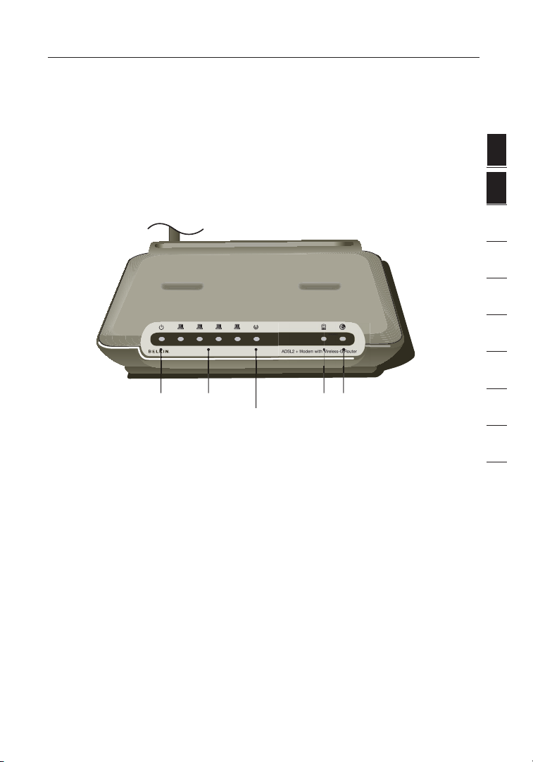
Front Panel
The following illustration shows the front panel of the Router:
Power LED
LED Indicators
The Router is equipped with nine LEDs on the front panel as described in the
table on the next page (from left to right):
LAN Status
LED (1-4)
Wireless LAN (WLAN)
Status LED
ADSL LED
Internet LED
1
secti on
2
3
4
5
6
7
8
9
10
11
5
Page 8

Knowing your Router
LED Color Status Description
ADSL
Green OFF Power off or ADSL line connection is physically
disconnected
Blinking Handshaking or training is in progress
Solid ADSL line connection is OK
Wireless
Green OFF Power off or no radio signal (WLAN card is not present or
fails to function)
Blinking Traffic is going through wireless LAN interface
Solid Wireless LAN interface ready to work
Internet
Green OFF No Internet connection
Blinking Transmitting or receiving data
Solid Connected to the Internet
LAN 1 to
LAN 4
Green OFF Power off or no Ethernet carrier is present
LA N
-
Blinking Ethernet carrier is present and user data is going through
Ethernet port
Solid Ethernet carrier is present
Power
Green OFF Power off
Solid Power on
6
Page 9
7
Knowing your Router
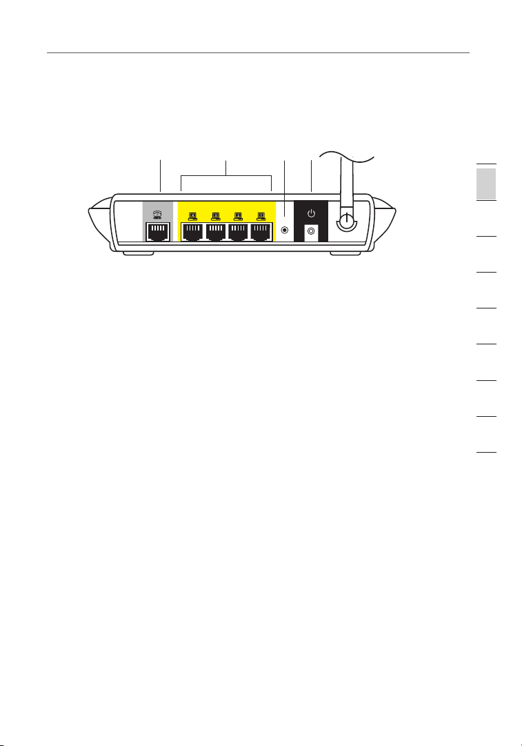
Rear Panel
The following figure illustrates the rear panel of your Router.
(8) (7)(9)(6)
Power Plug — Connect the included power supply to this inlet. Using the wrong
type of power adapter may cause damage to your Router.
Ethernet Ports
ports are labeled 1 through 4. These ports correspond to the numbered LEDs
on the front of the Router. Connect your network-enabled computers or any
networking devices to one of these ports.
ADSL Line —This port is for connection to your ADSL line. Connect your ADSL
line to this port.
Reset Button —The “Reset” button is used in rare cases when the Router
may function improperly. Resetting the Router will restore the Router’s normal
operation while maintaining the programmed settings. You can also restore the
factory default settings by using the “Reset” button. Use the restore option in
instances where you may have forgotten your custom password.
a. Resetting the Router
Push and hold the “Reset” button for one second then release it. When the
“Power/Ready” light becomes solid again, the reset is complete.
b. Restoring the Factory Defaults
Press and hold the “Reset” button for 20 seconds then release it. When the
“Power/Ready” light becomes solid again, the restore is complete.
—The Ethernet ports are RJ45, 10/100 auto-negotiation. The
1
secti on
2
3
4
5
6
7
8
9
10
11
7
Page 10
Connecting and Configuring your Router
Setup Assistant
Belkin has provided Setup Assistant software to make installing your Router a simple
and easy task. You can use it to get your Router up and running in minutes. The Setup
Assistant requires that your Windows 2000, XP, or Vista™ computer be connected
directly to your ADSL and that the Internet connection is active and working at the
time of installation. If it is not, you must use the “Alternate Setup Method” section of
this User Manual to configure your Router. Additionally, if you are using an operating
system other than Windows 2000, XP, or Vista, or Mac OS X, you must use the
“Alternate Setup Method” section of this User Manual.
Step 1A: Hardware Connections – Follow the
Quick Installation Guide (QIG)
New Router Setup
Follow these steps if you are NOT replacing an existing modem. If you are replacing
an existing modem, skip to the next section, “Replacing an Existing Modem or
Modem Router”, starting on page 9.
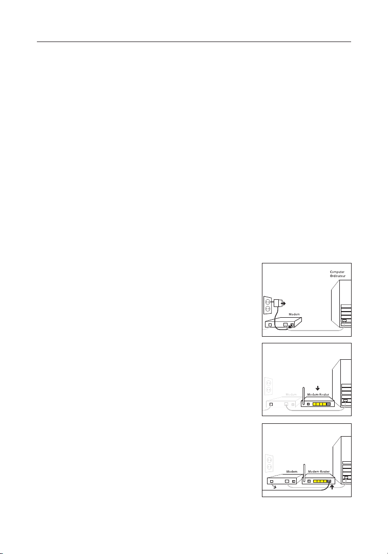
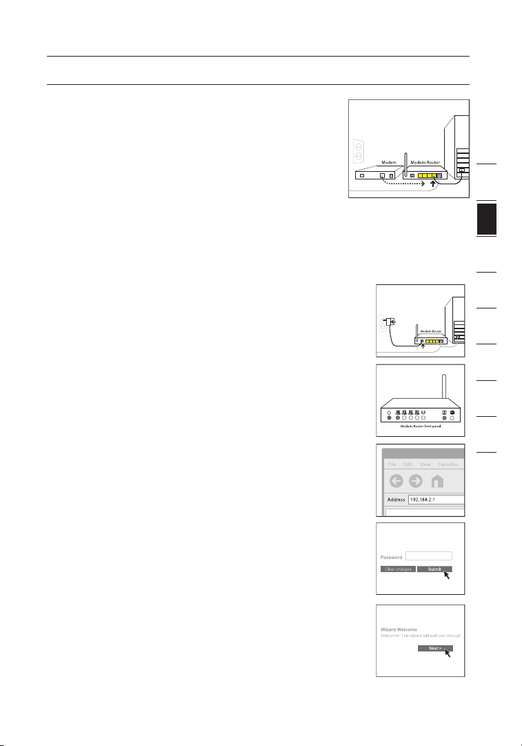
1A.1 Unpack your new Router from
the box and place it next to your
computer. Raise the Router’s
antenna.
1A.
2 Retrieve the yellow RJ45 cable that
was included with your Router. First,
connect one end to any yellow port
labeled “Wired Computers” on the
back of your Router. Then, connect
the other end to the networking
port on the back of your computer.
[Insert Ethernet logo]
1A.
3 Retrieve the included gray RJ11
phone cord. Connect one end to the
gray port labeled “DSL” on the back
of your Router. Then, connect the
other end to your ADSL connection
(either a wall jack or an ADSL
splitter).
Note :
Some ADSL connections require a
microfilter. Your ADSL provider can tell you
if you need one. Belkin includes a microfilter
in regions known to use them. To determine
if you need a microfilter, please refer to your
ADSL provider’s user manual.
8
Page 11
9
Connecting and Configuring your Router
1A.4 Plug your Router’s power supply into the
black port labeled “Power” on the back of
your Router. Wait 20 seconds for the Router
to start up. Look at the display on the front
of the Router. Make sure the “Wired” and
“Modem-Router” icons are lit in green. If they
are not, recheck your connections.
Step 1B: Replacing an Existing Modem or Modem Router
Follow these steps if you currently have a modem or a modem router that you
will be replacing with your new Router.
1B.1
Unpack your new Router from the box and
place it next to your old modem. Raise the
Router’s antenna. Unplug your old modem’s
power cord.
1B.2 Locate the cable that connects your old
modem to your computer. Unplug that cable
from your old modem, and plug it into any
yellow port labeled “Wired Computers” on
the back of your new Router.
1B.3 Locate the cable that connects your old
modem to the ADSL wall jack. Unplug it from
your old modem and then connect it to the
gray port labeled “DSL” on the back of your
Router.
1B.4 Plug your Router’s power supply into the
1B.5
black port labeled “Power” on the back of
your Router.
Wait 20 seconds for the Router to start up.
Look at the display on the front of the Router.
Make sure the “ADSL” and “LAN” LEDs are
lit in green. If they are not, recheck your
connections.
1
2
3
4
5
6
7
8
9
10
11
secti on
9
Page 12
Connecting and Configuring your Router
Step 2: Set Up the Router – Run the Setup Assistant Software
2.1 Shut down any programs that are running on your computer at this time.Turn
off any firewall or Internet-connection-sharing software on your computer.
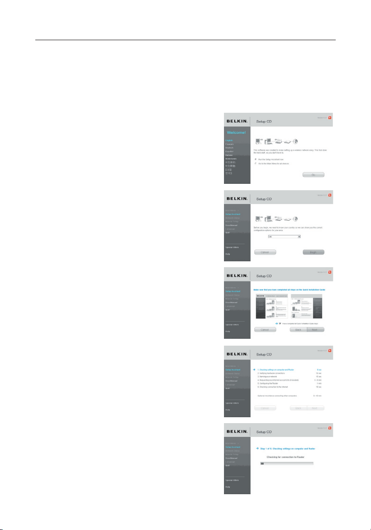
2.2 Insert the CD into your computer. The
Setup Assistant will automatically appear
on your computer’s screen within 15
seconds. Click on “Go” to run the Setup
Assistant. Follow the instructions there.
IMPORTANT: Run the Setup Assistant from
the computer that is directly
connected to the Router from
Step 1A.2.
Note for Windows Users: If the Setup
Assistant does not start up automatically,
select your CD-ROM drive from “My
Computer” and double-click on the file
named “SetupAssistant” to start the Setup
Assistant.
2.3 Select Country. Select your country from
the drop-down box. Click “Begin” to
continue.
2.4 Confirmation Screen. Verify that you have
completed all QIG steps by checking the
box to the right of the arrow. Click “Next”
to continue.
2.5 Progress Screen Setup Assistant will show
you a progress screen each time a step in
the setup has been completed.
2.6 Checking Settings. The Setup Assistant
will now examine your computer’s network
settings and gather information needed to
complete the Router’s connection to the
Internet.
10
Page 13
11
Connecting and Configuring your Router
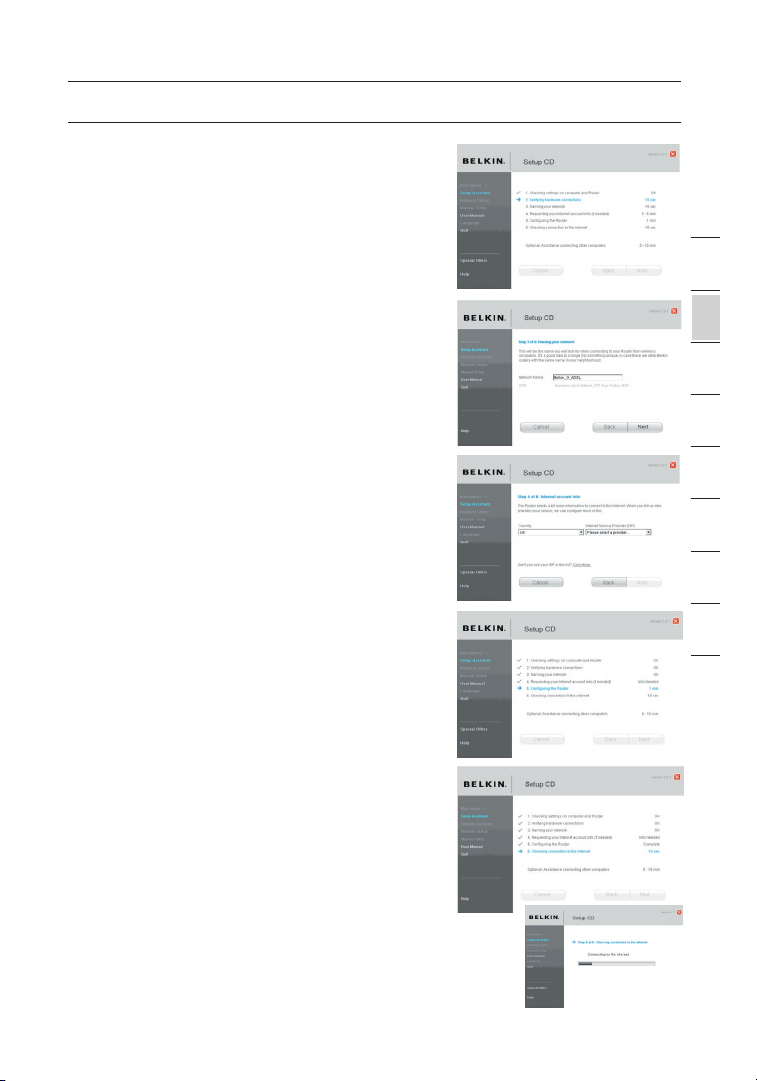
2.7 Verifying Hardware Connections
The Setup Assistant will now verify your
hardware connection.
2.8 Naming your Wireless Network
The Setup Assistant will display the default
wireless network name or Service Set
Identifier (SSID). This is the name of your
wireless network to which your computers
or devices with wireless network adapters
will connect. You can either use the
default or change it to something unique.
Write down this name for future reference.
Click “Next” to continue.
2.9 Requesting Internet Account Info (if
needed)
If your Internet account requires a login
and password, you will be prompted with
a screen similar to the illustration below.
Select your country or ISP from the dropdown boxes.
2.10 Configuring the Router
The Setup Assistant will now configure
your Router by sending data to the Router
and restarting it. Wait for the on-screen
instructions.
Note: Do not disconnect any cable or power
off the Router while the Router is rebooting.
Doing so will render your Router inoperable.
2.11 Checking Internet Connection
We are almost done. The Setup Assistant
will now check your connection to the
Internet.
1
2
3
4
5
6
7
8
9
10
11
secti on
11
Page 14

Connecting and Configuring your Router
Congratulations
You have finished installing your new Belkin
Router. You will see the Congratulations
screen when your Router can connect to the
Internet. You can begin surfing by opening
your browser and going to any website.
You can use the Setup Assistant to set up
your other wired and wireless computers to
connect to the Internet by clicking “Next”. If
you decide to add computers to your Router
later, select “Exit the Assistant” and then click
“Next”.
Troubleshooting
If the Setup Assistant is not able to connect
to the Internet, you will see the following
screen. Follow the on-screen instructions to
go through the troubleshooting steps.
2.12 Optional: Assistance Connecting Other
Computers. This optional step will help
you to connect additional wired and
wireless computers to your network.
Follow the on-screen instructions.
Once you have verified that your other
wired and wireless computers are properly
connected, your network is set up and
working. You can now surf the Internet.
Click “Next” to take you back to the main
menu.
12
Page 15
13
Manually Configuring your Router
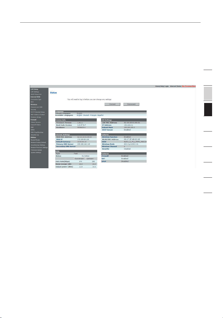
Understanding the Web-Based User Interface
The home page shows you a quick view of the Router’s status and settings. All
advanced setup pages can be reached from this page.
Using Web-Based Manager
Once your host PC is properly configured, start your web browser and type the private
IP address of the Router into the URL field: “192.168.2.1” and then click “Enter”.
1. Quick-Navigation Links
You can go directly to any of the Router’s UI pages by clicking directly on
these links. The links are divided into logical categories and grouped by tabs to
make finding a particular setting easier to find. Clicking on the header of each
tab will show you a short description of the tab’s function.
2. Home Button
The “Home” button is available in every page of the UI. Pressing this button
will take you back to the home page.
3. Help Button
The “Help” button gives you access to the Router’s help pages. Help is also
available on many pages by clicking “more info” next to certain sections of
each page.
4. Login/Logout Button
This button enables you to log in and out of the Router with the press of one
button. When you are logged into the Router, this button will change to read
“Logout”. Logging into the Router will take you to a separate login page where
you will need to enter a password. When you are logged into the Router, you
can make changes to the settings. When you are finished making changes, you
can log out of the Router by clicking the “Logout” button. For more information
about logging into the Router, see the section called “Logging into the Router”.
13
1
2
3
4
5
6
7
8
9
10
11
secti on
Page 16

Manually Configuring your Router
5. Internet Status Indicator
This indicator is visible in all pages of the Router, showing the connection
status of the Router. When the indicator says “connection OK” in GREEN,
the Router is connected to the Internet. When the Router is not connected to
the Internet, the indicator will read “no connection” in RED. The indicator is
automatically updated when you make changes to the settings of the Router.
6. LAN Settings
Shows you the settings of the Local Area Network (LAN) side of the
Router.Changes can be made to the settings by clicking the “LAN” “Quick
Navigation”link on the left side of the screen.
7. Features
Shows the status of the Router’s NAT, firewall, and wireless features. Changes
can be made to the settings by clicking on any one of the links or by clicking
the “Quick Navigation” links on the left side of the screen.
8. Internet Settings
Shows the settings of the Internet/WAN side of the Router that connects to
the Internet. Changes to any of these settings can be made by clicking on the
“Internet/WAN” “Quick Navigation” link on the left side of the screen.
9. Version Info
Shows the firmware version, boot-code version, hardware version, and serial
number of the Router.
10. Page Name
The page you are on can be identified by this name. This manual will
sometimes refer to pages by name. For instance, “LAN > LAN Settings” refers
to the “LAN Settings” page.
14
Page 17
15
Manually Configuring your Router
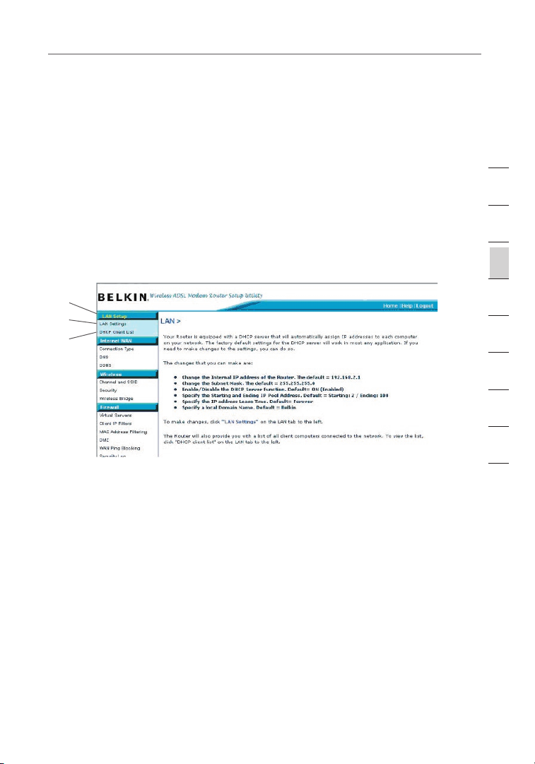
Changing LAN Settings
All settings for the internal LAN setup of the Router can be viewed and changed
here.
LAN Settings
Clicking on the header of the LAN tab (A) will take you to the LAN tab’s header
page. A quick description of the functions can be found here. To view the settings
or make changes to any of the LAN settings, click on “LAN Settings” (B) or to view
the list of connected computers, click on “DHCP Client List” (C).
(A)
(B)
(C)
IP Address
The “IP address” is the internal IP address of the Router. The default IP address
is “192.168.2.1”. To access the advanced setup interface, type this IP address
into the address bar of your browser. This address can be changed if needed. To
change the IP address, type in the new IP address and click “Apply Changes”. The
IP address you choose should be a non-routable IP. Examples of a non-routable IP
are:
192.168.x.x (where x is anything between 0 and 255)
10.x.x.x (where x is anything between 0 and 255)
1
2
3
4
5
6
7
8
9
10
11
secti on
Subnet Mask
There is no need to change the subnet mask. This is a unique, advanced feature of
your Belkin Router.
15
Page 18

Manually Configuring your Router
DHCP Server
The DHCP server function makes setting up a network very easy by assigning IP
addresses to each computer on the network automatically. The default setting is
“On”. The DHCP server can be turned OFF if necessary; however, in order to do so,
you must manually set a static IP address for each computer on your network. To
turn off the DHCP server, select “Off” and click “Apply Changes”.
IP Pool
The range of IP addresses set aside for dynamic assignment to the computers on
your network. If you want to change this number, you can do so by entering a new
starting and ending IP address and clicking on “Apply Changes”. The starting IP
address must be lower in number than the ending IP address.
Lease Time
The length of time the DHCP server will reserve the IP address for each computer.
We recommend that you leave the lease time set to “Forever”. The default setting
is “Forever”, meaning that any time a computer is assigned an IP address by the
DHCP server, the IP address will not change for that particular computer. Setting
lease times for shorter intervals such as one day or one hour frees IP addresses
after the specified period of time. This also means that a particular computer’s IP
address may change over time. If you have set any of the other advanced features
of the Router such as DMZ or client IP filters, these are dependent on the IP
address. For this reason, you will not want the IP address to change.
Local Domain Name
You can set a local domain name (network name) for your network. There is no
need to change this setting unless you have a specific advanced need to do so. You
can name the network anything you want such as “MY NETWORK”.
DHCP Client List
You can view a list of the computers, which are connected to your network. You are
able to view the IP address of the computer, the host name (name of the computer
in your network), and the MAC address of the computer’s network interface card
(NIC). Pressing the “Refresh” button will update the list. If there have been any
changes, the list will be updated.
16
Page 19

17
Manually Configuring your Router
Internet WAN
The “Internet WAN” tab is where you will set up your Router to connect to your
Internet Service Provider (ISP). The Router is capable of connecting to virtually
any ADSL Service Provider’s system provided you have correctly configured the
Router’s settings for your ISP’s connection type. Your connection settings are
provided to you by your ISP.
To configure the Router with the settings that your ISP gave you, click
“Connection Type” (1) on the left side of the screen. Select the connection type
you use. If your ISP gave you DNS settings, clicking “DNS” (2) allows you to
enter DNS address entries for ISPs that require specific settings. When you have
finished making settings, the “Internet Status” indicator will read “Connected” if
your Router is set up properly.
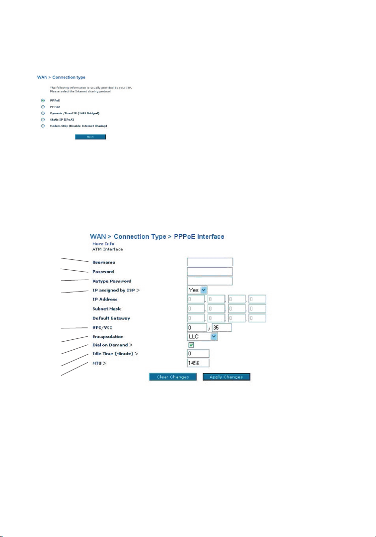
Connection Type
From the “Connection Type” page, you can select one of these five
connection types based on the instruction provided by your ISP:
PPPoE
PPPoA
Dynamic IP (1483 Bridged)
Static IP (IPoA)
Modem Only (Disable Internet Sharing)
Note: If you are not sure which connection type to select, please contact your ISP.
Select the type of connection you use by clicking the radio button next to your
connection type and then clicking “Next”.
1
2
3
4
5
6
7
8
9
10
11
11
secti on
17
Page 20
Manually Configuring your Router
Setting your ISP Connection Type to PPPoE or PPPoA
PPPoE (Point-to-Point Protocol over Ethernet) is the standard method of connecting
networked devices. It requires a user name and password to access the network of
your ISP for connecting to the Internet. PPPoA (PPP over ATM) is similar to PPPoE,
but is mostly implemented in the UK. Select PPPoE or PPPoA and click “Next”.
Then, enter the information provided by your ISP, and click “Apply Changes” to
activate your settings.
(1)
(2)
(3)
(4)
(5)
(6)
(7)
(8)
(9)
1. User Name — Enter the user name. (Assigned by your ISP).
2. Password — Enter your password. (Assigned by your ISP).
3. Retype Password — Confirm the password.
(Assigned by your ISP).
4. IP Assigned by ISP — Leave “Yes” if your ISP automatically assigns an IP
address. If your ISP assigned a fixed IP address, select “No” and enter assigned
values.
18
Page 21
19
Manually Configuring your Router
5. VPI/VCI — Enter your Virtual Path Identifier (VPI) and Virtual Circuit Identifier
(VCI) parameter here. (Assigned by your ISP).
6. Encapsulation — Select your encapsulation type (supplied by your ISP) to
specify how to handle multiple protocols at the ATM transport layer. VC-MUX:
PPPoA Virtual Circuit Multiplexer (null encapsulation) allows only one protocol
running per virtual circuit with fewer overheads. LLC: PPPoA Logical Link Control
allows multiple protocols running over one virtual circuit (more overhead).
7. Dial on Demand — By selecting “Dial on Demand”, your Router will
automatically connect to the Internet when a user opens up a web browser.
8. Idle Time (Minutes) — Enter the maximum idle time for the Internet connection.
After this time has been exceeded, the connection will be terminated.
9. MTU — The MTU setting should never be changed unless your ISP requires a
specific MTU setting. Making changes to the MTU can cause problems with your
Internet connection, including disconnection from the Internet, slow Internet
access, and problems with Internet applications working properly.
1
2
3
4
5
6
7
8
9
10
11
secti on
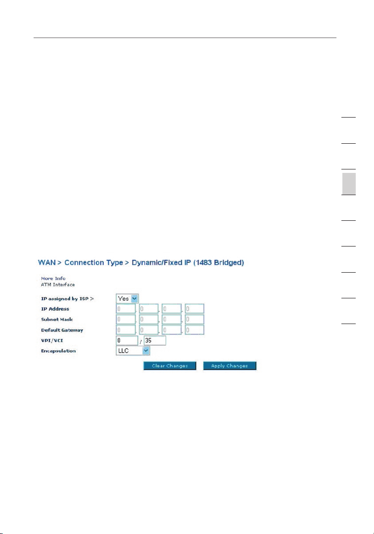
Setting your Connection Type to Dynamic IP (1483 Bridged)
This connection method bridges your network and ISP’s network together. The
Router will obtain an IP address automatically from your ISP’s DHCP server.
19
Page 22
Manually Configuring your Router
(1)
(2)
(3)
1. IP Assigned by ISP — Leave “Yes” if your ISP automatically assigns an IP
address. If your ISP assigned a fixed IP address, select “No” and enter assigned
values.
2. VPI/VCI — Enter your VPI and VCI parameter here. These identifiers are
assigned by your ISP.
3. Encapsulation — Select LLC or VC MUX your ISP uses.
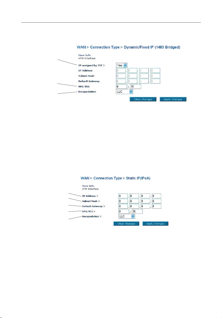
Setting your ISP Connection Type to Static IP (IPoA)
This connection type is also called “Classical IP over ATM” or “CLIP”, which your
ISP provides a fixed IP for your Router to connect to the Internet.
(1)
(2)
(3)
(4)
(5)
1. IP Address — Enter an IP address assigned by your ISP for the Router WAN
interface.
2. Subnet Mask — Enter a subnet mask assigned by your ISP.
3. Default Gateway — Enter a default gateway IP address. If the Router cannot find
the destination address within its local network, it will forward the packets to the
default gateway assigned by your ISP.
4. VPI/VCI — Enter your VPI and VCI parameter here. These identifiers are
assigned by your ISP.
5. Encapsulation — Select LLC or VC MUX your ISP uses.
20
Page 23

21
Manually Configuring your Router
Setting your Connection Type to Modem Only (Disable Internet Sharing)
In this mode, the Router simply acts as a bridge passing packets across the DSL
port. It requires additional software to be installed on your computers in order to
access the Internet.
(1)
(2)
1. VPI/VCI — Enter your VPI and VCI parameter here. (Assigned by your ISP).
2. Encapsulation — Select LLC or VC MUX. (Assigned by your ISP).
DNS (Domain Name Server) Settings
A “Domain Name Server” is a server located on the Internet that translates
Universal Resource Links (URLs) like “www.belkin.com” to IP addresses. Many
ISPs do not require you to enter this information into the Router. The “Automatic
from ISP” box (1) [Designer: call this out in screenshot below] should be checked
if your ISP did not give you a specific DNS address. If you are using a static
IP connection type, then you may need to enter a specific DNS address and
secondary DNS address for your connection to work properly. If your connection
type is dynamic or PPPoE, it is likely that you do not have to enter a DNS
address.
1
2
3
4
5
6
7
8
9
10
11
secti on
Leave the “Automatic from ISP” box checked. To enter the DNS address
settings, uncheck the “Automatic from ISP” box and enter your DNS entries
in the spaces provided. Click “Apply Changes” (2) [Designer: call this out in
screenshot below] to save the settings.
(1)
(2)
21
Page 24
Manually Configuring your Router
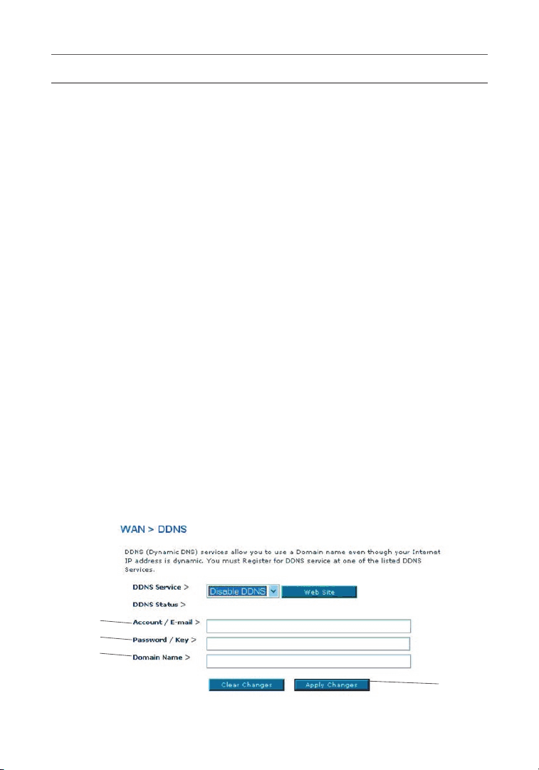
Using DDNS (Dynamic DNS)
The DDNS service allows you to alias a dynamic IP address to a static host name
in any of the many domains DynDNS.org offers, allowing your network computers
to be more easily accessed from various locations on the Internet. DynDNS.org
provides this service, for up to five host names, free to the Internet community.
TZO.com is another alternative to DynDNS.org. DDNS service is ideal for a home
website, file server, or to make it easy to access your home PC and stored files
while you’re at work. Using the service can ensure that your host name always
points to your IP address, no matter how often your ISP changes it. When your IP
address changes, your friends and associates can always locate you by visiting
yourname.dyndns.org instead! To register free for your Dynamic DNS host name,
please visit http://www.dyndns.org.
Setting up the Router’s Dynamic DNS Update Client
You must register with DynDNS.org’s free update service before using this
feature. Once you have your registration, follow the directions below.
1. Enter your DynDNS.org user name in the “Account / E-mail” field (1).
2. Enter your DynDNS.org password in the “Password / Key” field (2).
3. Enter the DynDNS.org domain name you set up with DynDNS.org in the
“Domain Name” field (3).
4. Click “Apply Changes” to update your IP address.
Whenever your IP address assigned by your ISP changes, the Router will
automatically update DynDNS.org’s servers with your new IP address. You can
also do this manually by clicking the “Apply Changes” button (4).
From the “Connection Type” page, you can select the type of connection you w
ant to use by selecting the “Connection Type” from the pull-down list.
(1)
(2)
(3)
(4)
22
Page 25

23
Manually Configuring your Router
Wireless
The “Wireless” tab lets you make changes to the wireless network settings. From
this tab, you can make changes to the wireless network name (SSID), operating
channel, and encryption security settings.
Channel and SSID
1. Changing the Wireless Network Name (SSID)
To identify your wireless network, a name called the SSID (Service Set Identifier)
is used. You can change this to anything you want to or you can leave it
unchanged. If there are other wireless networks operating in your area, you will
want to make sure that your SSID is unique (does not match that of another
wireless network in the area). To change the SSID, type in the SSID that
you want to use in the SSID field and click “Apply Changes”. The change is
immediate. If you make a change to the SSID, your wireless-equipped computers
may also need to be reconfigured to connect to your new network name. Refer
to the documentation of your wireless network adapter for information on making
this change.
1
2
3
4
5
6
7
8
9
10
11
secti on
2. Using the ESSID Broadcast Feature
For security purposes, you can choose not to broadcast your network’s SSID.
Doing so will keep your network name hidden from computers that are scanning
for the presence of wireless networks. To turn off the broadcast of the SSID,
select “DISABLE” and then click “Apply Changes”. The change is immediate. Each
computer now needs to be set to connect to your specific SSID; an SSID of “ANY”
will no longer be accepted. Refer to the documentation of your wireless network
adapter for information on making this change.
Note: This advanced feature should be employed by advanced users only.
23
Page 26

Manually Configuring your Router
3. Using the Wireless Mode Switch
Your Router can operate in three different wireless modes: “Mixed (11b+11g)”, “11g
Only”, and “11b Only”. The different modes are explained below.
Mixed (11b+11g) Mode
In this mode, the Router is compatible with 802.11b and 802.11g wireless clients
simultaneously. This is the factory default mode and ensures successful operation
with all devices compatible with Wi-Fi®. If you have a mix of 802.11b and 802.11g
clients in your network, we recommend that you keep the default setting. This
setting should only be changed if you have a specific reason to do so.
11g-Only Mode
802.11g-Only mode works with 802.11g clients only. This mode is recommended
only if you want to prevent 802.11b clients from accessing your network. To switch
modes, select the desired mode from the “Wireless Mode” drop-down box. Then,
click “Apply Changes”.
11b-Only Mode
We recommend you DO NOT use this mode unless you have a very specific reason
to do so. This mode exists only to solve unique problems that may occur with some
802.11b client adapters and is NOT necessary for interoperability of 802.11g and
802.11b standards.
4. Changing the Wireless Channel
There are a number of operating channels from which to choose. In the United
States, there are 11 channels. In the United Kingdom and most of Europe, there
are 13 channels. In a small number of other countries, there are other channel
requirements. Your Router is configured to operate on the proper channels in
which the country you reside. The default is “Auto”. The channel can be changed if
needed. If there are other wireless networks operating in your area, your network
should be set to operate on a channel that is different than the other wireless
networks. For best performance, use a channel that is at least five channels away
from the other wireless network. For instance, if another network is operating on
channel 11, then set your network to channel 6 or below. To change the channel,
select the channel from the drop-down list. Click “Apply Changes”. The change is
immediate.
24
Page 27

25
Manually Configuring your Router
Encryption/Security
Securing your Wi-Fi Network
Here are a few different ways you can maximize the security of your wireless
network and protect your data from prying eyes and ears. This section is intended
for the home, home-office, and small-office user. At the time of this User Manual’s
publication, there are four encryption methods available.
Name 64-Bit Wired
Equivalent
Privacy
Acronym 64-bit WEP 128-bit WEP WPA-TKIP/
Security Good Better Best Best
Features Static keys Static keys Dynamic key
Encryption
keys based
on RC4
algorithm
(typically 40bit keys)
128-Bit Wired
Equivalent
Privacy
More secure
than 64-bit
WEP using
a key length
of 104 bits
plus 24
additional bits
of systemgenerated
data
Wi-Fi
Protected
Access-TKIP
AES (or just
WPA)
encryption
and mutual
authentication
TKIP
(Temporal
Key Integrity
Protocol)
added so
that keys are
rotated and
encryption is
strengthened
Wi-Fi
Protected
Access 2
WPA2-AES
(or just WPA2)
Dynamic key
encryption
and mutual
authentication
AES
(Advanced
Encryption
Standard)
does not
cause any
throughput
loss
1
2
3
4
5
6
7
8
9
10
11
secti on
Wired Equivalent Privacy (WEP)
WEP is a common protocol that adds security to all wireless products that are
compliant with Wi-Fi. WEP was designed to give wireless networks the equivalent
level of privacy protection as a comparable wired network.
64-Bit WEP
64-bit WEP was first introduced with 64-bit encryption, which includes a key length
of 40 bits plus 24 additional bits of system-generated data (64 bits total). Some
hardware manufacturers refer to 64-bit as 40-bit encryption. Shortly after the
technology was introduced, researchers found that 64-bit encryption was too easy
to decode.
25
Page 28

Manually Configuring your Router
128-Bit WEP
As a result of 64-bit WEP’s potential security weaknesses, a more secure method of
128-bit encryption was developed. 128-bit encryption includes a key length of 104
bits plus 24 additional bits of system-generated data (128 bits total). Some hardware
manufacturers refer to 128-bit as 104-bit encryption. Most of the new wireless
equipment in the market today supports both 64-bit and 128-bit WEP encryption, but
you might have older equipment that only supports 64-bit WEP. All Belkin wireless
products will support both 64-bit and 128-bit WEP.
Encryption Keys
After selecting either the “64-bit” or “128-bit WEP” encryption mode, it is critical
that you generate an encryption key. If the encryption key is not consistent
throughout the entire wireless network, your wireless networking devices will be
unable to communicate with one another on your network and you will not be able to
successfully communicate within your network. You can enter your key by typing in
the hex key manually, or you can type in a passphrase in the “Passphrase” field and
click “Generate” to create a key. A hex (hexadecimal) key is a mixture of numbers and
letters from A–F and 0–9. For 64-bit WEP, you need to enter 10 hex keys. For 128-bit
WEP, you need to enter 26 hex keys.
For instance:
AF 0F 4B C3 D4 = 64-bit WEP key
C3 03 0F AF 0F 4B B2 C3 D4 4B C3 D4 E7 = 128-bit WEP key
The WEP passphrase is NOT the same as a WEP key. Your wireless card uses this
passphrase to generate your WEP keys, but different hardware manufacturers
might have different methods for generating the keys. If you have equipment from
multiple vendors in your network, you can use the hex WEP key from your Router or
access point and enter it manually into the hex WEP key table in your wireless card’s
configuration screen.
Wi-Fi Protected Access (WPA)
WPA is a new Wi-Fi standard that was designed to improve upon the security
features of WEP. To use WPA security, the drivers and software of your wireless
equipment must be upgraded to support WPA. These updates will be found on the
wireless vendors’ websites. There are two types of WPA security: WPA-PSK (no
server) and WPA (with 802.1x radius server).
WPA-PSK (no server)
This method uses what is known as a “pre-shared key” as the network key. A
network key is basically a password that is between eight and 63 characters long.
It can be a combination of letters, numbers, or characters. Each client uses the
same network key to access the network. Typically, this is the mode that will be
used in a home environment.
26
Page 29

27
Manually Configuring your Router
WPA (with 802.1x radius server)
With this system, a radius server distributes the network key to the clients
automatically. This is typically found in a business environment.
WPA2
The Router features WPA2, which is the second generation of the WPA-based
802.11i standard. It offers a higher level of wireless security by combining
advanced network authentication and stronger AES encryption methods.
WPA2 Requirements
IMPORTANT: In order to use WPA2 security, all your computers and wireless client
adapters must be upgraded with patches, drivers, and client utility software that
support WPA2. At the time of this User Manual’s publication, a couple security
patches are available, for free download, from Microsoft®. These patches work only
with the Windows XP operating system. Other operating systems are not supported
at this time.
For a Windows XP computer that does not have Service Pack 2 (SP2), a file from
Microsoft called “Windows XP Support Patch for Wireless Protected Access
(KB 826942)” is available for free download at http://www.microsoft.com/
downloads/details.aspx?displaylang=en&familyid=009D8425-CE2B-47A4-ABEC274845DC9E91.
For Windows XP computers with SP2, Microsoft has released a free download
to update the wireless client components to support WPA2 (KB893357). The
update can be download from: http://www.microsoft.com/downloads/details.
aspx?FamilyID=662bb74d-e7c1-48d6-95ee-1459234f4483&DisplayLang=en.
IMPORTANT: You also need to ensure that all your wireless client cards and
adapters support WPA2, and that you have downloaded and installed the latest
driver. Most of the Belkin wireless cards have updated drivers available for
download from the Belkin support site: www.belkin.com/networking. For a list of
Belkin wireless products that support WPA/WPA2, please visit our website at www.
belkin.com/networking.
Sharing the Same Network Keys
Most Wi-Fi products ship with security turned off. So, once you have your network
working, you need to activate WEP or WPA and make sure your wireless networking
devices are sharing the same network key.
1
2
3
4
5
6
7
8
9
10
11
secti on
27
Page 30
Manually Configuring your Router
Using a Hexadecimal Key
A hexadecimal key is a mixture of numbers and letters from A–F and 0–9. 64-bit
keys are five 2-digit numbers. 128-bit keys are 13 2-digit numbers.
For instance:
AF 0F 4B C3 D4 = 64-bit key
C3 03 0F AF 0F 4B B2 C3 D4 4B C3 D4 E7 = 128-bit key
In the boxes below, make up your key by writing in two characters
between A–F and 0–9 in each box. You will use this key to program the
encryption settings on your Router and your wireless computers.
Note to Mac users: Original Apple® AirPort® products support 64-bit encryption
only. Apple AirPort 2 products can support 64-bit or 128-bit encryption. Please
check your product to see which version you are using. If you cannot configure your
network with 128-bit encryption, try 64-bit encryption.
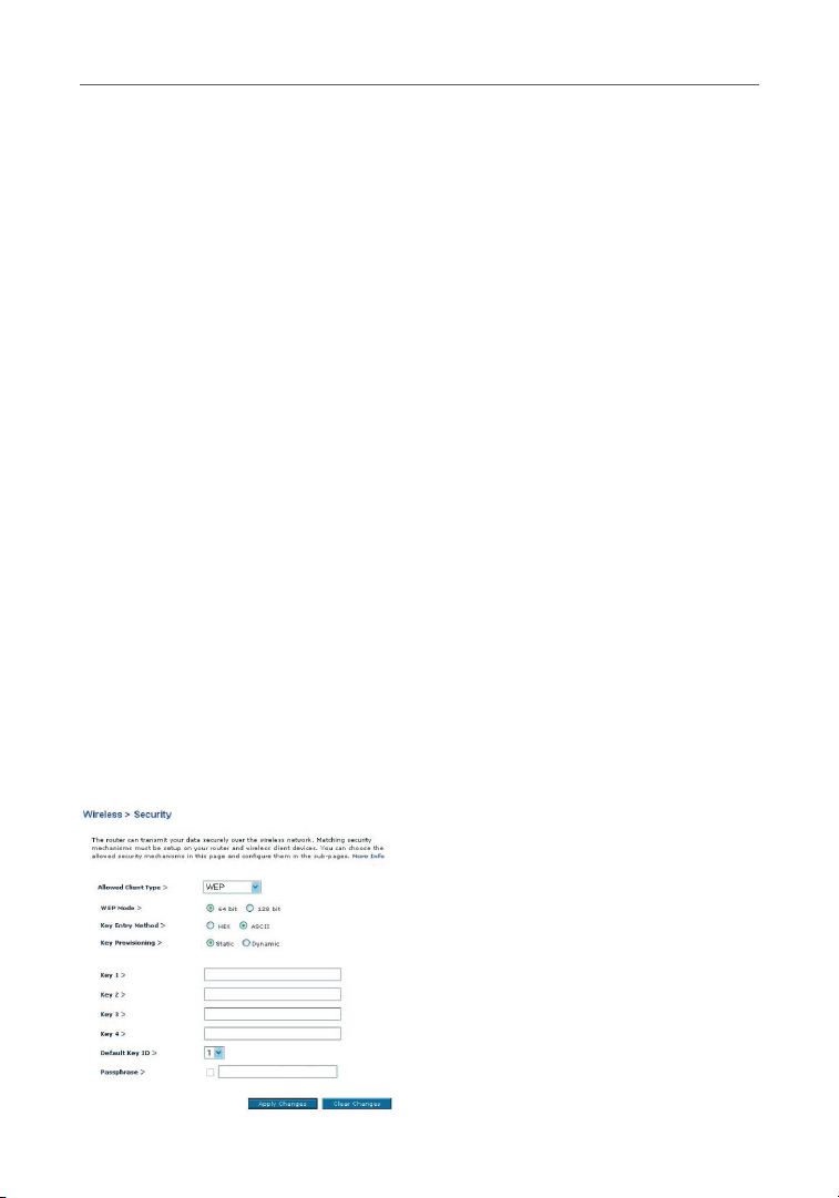
WEP Setup
1. Select “WEP” from the drop-down menu.
2. Select “WEP Mode” of 64-bit or 128-bit.
3. After selecting your WEP mode, you can enter your key by typing in the hex
key manually.
A hex (hexadecimal) key is a mixture of numbers and letters from A–F and 0–9. For
64-bit WEP, you need to enter 10 hex keys. For 128-bit WEP, you need to enter 26
hex keys.
For instance:
AF 0F 4B C3 D4 = 64-bit key
C3 03 0F AF 0F 4B B2 C3 D4 4B C3 D4 E7 = 128-bit key
28
Page 31

29
Manually Configuring your Router
3. Click “Apply Changes” to finish. Encryption in the Router is now set. Each of
your computers on your wireless network will now need to be configured with
the same security settings.
WARNING: If you are configuring the Wireless Router from a computer with a
wireless client, you will need to ensure that security is turned ON for this wireless
client. If this is not done, you will lose your wireless connection.
Changing the Wireless Security Settings
Your Router is equipped with WPA/WPA2, the latest wireless security standard. It
also supports the legacy security standard, WEP. By default, wireless security is
disabled. To enable security, you must first determine which standard you want to
use. To access the security settings, click “Security” on the “Wireless” tab.
WPA Setup
Note: To use WPA security, all your clients must be upgraded to drivers and
software that support it. At the time of this User Manual’s publication, a security
patch download is available free from Microsoft. This patch works only with the
Windows XP operating system. You also need to download the latest driver for your
Belkin Wireless G Desktop or Notebook Card from the Belkin support site. Other
operating systems are not supported at this time. Microsoft’s patch only supports
devices with WPA-enabled drivers such as Belkin 802.11g products.
There are two types of WPA security: WPA-PSK (no server) and WPA (with radius
server). WPA-PSK (no server) uses a so-called pre-shared key (PSK) as the security
key. A pre-shared key is a password that is between eight and 63 characters long.
It can be a combination of letters, numbers, and other characters. Each client uses
the same key to access the network. Typically, this mode will be used in a home
environment. WPA (with radius server) is a configuration wherein a radius server
distributes the keys to the clients automatically. This is typically used in a business
environment. WPA2 is the second generation of WPA, offering a more advanced
encryption technique over WPA.
Setting WPA/WPA2-PSK (no server)
1. From the “Allowed Client Type” drop-down menu, select “WPA/WPA2”.
2. For “Authentication”, select “Pre-shared Key” for typical home/SOHO use. This
setting will have to be identical on the clients that you set up.
3. Enter your pre-shared key. This can be from eight to 63 characters and can be
letters, numbers, or symbols. This same key must be used on all of the clients
that you set up. For example, your pre-shared key might be something like:
“Smith family network key”.
1
2
3
4
5
6
7
8
9
10
11
secti on
29
Page 32

Manually Configuring your Router
4. Click “Apply Changes” to finish. You must now set all clients to match these
settings.
Setting WPA/WPA2 (with radius server) Settings
If your network uses a radius server to distribute keys to the clients, use this
setting.
1. From the “Allowed Client Type” drop-down menu, select “WPA/WPA2”.
2. For “Encryption Technique”, select “802.1x” for environments with RADIUS
servers. This setting will have to be identical on the clients that you set up.
3. Enter the session idle time-out of the radius server into the “Session Idle
Timeout” field.
4. Enter the key interval—how often the keys are distributed (in packets)—in the
“Re-Authentication Period” field.
5. Enter the waiting time after authentication failed in the “Quiet Period” field.
6. Enter the IP address and port number of the radius server into the “Server-IP”
and “Server-Port” fields.
7. Enter the radius key into the “Secret Key” field.
8. Click “Apply Changes” to finish. You must now set all clients to match these
settings.
30
Page 33

31
Manually Configuring your Router
Note: Make sure your wireless computers are updated to work with WPA2 and have
the correct settings to get proper connection to the Router.
Configuring your Belkin Wireless G Network Cards to Use Security
Note: This section provides information on how to configure your Belkin Wireless G
Network Cards to use security. At this point, you should already have your Wireless
Router or access point set to use WPA or WEP. In order for you to gain a wireless
connection, you will need to set your wireless notebook card and wireless desktop
card to use the same security settings.
Connecting your Computer to a Wireless Network
that Requires a 64-Bit or 128-Bit WEP Key
1. Double-click the “Signal Indicator” icon to bring up the “Wireless Network”
screen. The “Advanced” button will allow you to view and configure more
options of your wireless card.
2. Under the “Wireless Network Properties” tab, select a network name from the
“Available networks” list and click “Configure”.
3. Under “Data Encryption”, select “WEP”.
4. Ensure the check box, “Network key is provided for me automatically”, at the
bottom is unchecked. If you are using this computer to connect to a corporate
network, consult your network administrator if this box needs to be checked.
5. Type your WEP key in the “Network key” box.
1
2
3
4
5
6
7
8
9
10
11
secti on
31
Page 34

Manually Configuring your Router
Important: A WEP key is a mixture of numbers and letters from A–F and 0–9. For
128-bit WEP, you need to enter 26 keys. For 64-bit WEP, you need to enter 10 keys.
This network key needs to match the key you assign to your Router.
6. Click “OK” to save the settings.
Connecting your Computer to a Wireless Network
that Requires WPA-PSK (no server)
1. Double-click the “Signal Indicator” icon to bring up the “Wireless Network”
screen. The “Advanced” button will allow you to view and configure more
options of your wireless card.
2. Under the “Wireless Networks” tab, select a network name from the “Available
networks” list and click “Configure”.
3. Under “Network Authentication”, select “WPA-PSK (No Server)”.
4. Type your WPA key in the “Network key” box.
Important: WPA-PSK is a mixture of numbers and letters from A–Z and 0–9. For
WPA-PSK, you can enter eight to 63 keys. This network key needs to match the key
you assign to your Router.
32
Page 35

33
Manually Configuring your Router
1
2
3
4
secti on
5
6
5. Click “OK” to save the settings.
Connecting your Computer to a Wireless Network
that Requires WPA (with radius server)
1. Double-click the “Signal Indicator” icon to bring up the “Wireless Network”
screen. The “Advanced” button will allow you to view and configure more
options of your wireless card.
2. Under the “Wireless Networks” tab, select a network name from the “Available
networks” list and click “Configure”.
3. Under “Network Authentication”, select WPA.
4. Under the “Authentication” tab, select the settings that are indicated by your
network administrator.
33
7
8
9
10
11
Page 36

Manually Configuring your Router
5. Click “OK” to save the settings.
Setting up WPA for Wireless Desktop and Wireless Notebook
Cards that are NOT Manufactured by Belkin
For WPA wireless desktop and wireless notebook cards that are NOT manufactured
by Belkin and that are not equipped with WPA-enabled software, a file from
Microsoft called “Windows XP Support Patch for Wireless Protected Access” is
available as a free download.
Note: The file that Microsoft has made available works only with Windows XP.
Other operating systems are not supported at this time.
Important: You also need to ensure that the wireless card manufacturer supports
WPA and that you have downloaded and installed the latest driver from their
support site.
Supported Operating Systems:
• Windows XP Professional
• Windows XP Home Edition
Setting up Windows XP Wireless Network Utility to Use WPA-PSK
In order to use WPA-PSK, ensure you are using Windows Wireless Network Utility
by doing the following:
1. Under Windows XP, click “Start > Control Panel > Network Connections”.
2. Right-click on “Wireless Network Connection”, and select “Properties”.
3. Clicking on the “Wireless Networks” tab will display the following screen. Ensure
the “Use Windows to configure my wireless network settings” box is checked
4. Under the “Wireless Networks” tab, click the “Configure” button, and you will
see the following screen.
5. For a home or small-business user, select “WPA-PSK” under “Network
Authentication”.
34
Page 37

35
Manually Configuring your Router
Note: Select “WPA” if you are using this computer to connect to a corporate
network that supports an authentication server such as a radius server. Consult
your network administrator for further information.
6. Select “TKIP” or “AES” under “Data Encryption”. This setting will have to be
identical to the Router.
7. Type in your encryption key in the “Network Key” box.
Important: Enter your pre-shared key. This can be from eight to 63 characters
and can be letters, numbers, or symbols. This same key must be used on all of the
clients that you set up.
8. Click “OK” to apply settings.
Wireless Range Extension and Bridging
What is a Wireless Bridge?
A wireless bridge is actually an operation “mode” you can use to extend the range
of your wireless network, or add an extension of your network in another area of
your office or home without running cables.
Note: We can make no guarantees that this feature will interoperate with hardware
from other wireless manufacturers.
Note: Please make sure to download the latest firmware version for the Router for
optimal performance at: http://web.belkin.com/support.
Adding Another Network Segment Wirelessly
Connecting a network switch or hub to the Router’s RJ45 jack will allow a number
of computers connected to the switch access to the rest of the network.
1
2
3
4
5
6
7
8
9
10
11
secti on
35
Page 38

Manually Configuring your Router
Setting up a Bridge Between your Router and a Secondary Access Point
Bridging your Belkin Router to a secondary access point requires that you access the
Router’s Advanced Setup Utility and enter the MAC address of the access point in the
appropriate area. There are also a few other requirements.
PLEASE BE SURE TO FOLLOW THE STEPS BELOW CAREFULLY.
1. Set your access point to the same channel as the Router. For more information on
changing channels, see the “Wireless - Channel and SSID” section of this User Manual.
2. Find the access point’s MAC address on the bottom of the access point. There are
two MAC addresses on the bottom label. You will need the MAC address named
“WLAN MAC Address”. The MAC address starts with “0030BD” and is followed by
six other numbers or letters (i.e., 0030BD-XXXXXX). Write the MAC address below.
Go to the next step.
3. Place your secondary access point within range of your Router and near the area
where you want to extend the range or add the network segment. Typically, indoor
range should be between 100 and 200 feet.
4. Connect power to your access point. Make sure the access point is on and proceed
to the next step.
5. From a computer already connected to your Router, access the Advanced Setup
Utility by opening your browser. In the address bar, type in “192.168.2.1”. Do not
type in “www” or “http://” before the number. Note: If you have changed your
Router’s IP address, use that IP address.
6. You will see the Router’s user interface in the browser window. Click “Wireless
Bridge” (2) on the left-hand side of the screen. You will see the following screen.
7. Check the box that says, “Enable ONLY specific Access Points to connect” (1)].
(1)
(3)
36
Page 39

37
Manually Configuring your Router
8. In the field named “AP1” (3), type in the MAC address of your secondary access
point. When you have typed in the address, click “Apply Changes”.
9. Bridging is now set up.
Note: It may take up to a minute for the bridged connection to properly establish
itself. In some cases, it may be necessary to restart the access point and the
Router to initiate the bridge.
Firewall
Your Router is equipped with a firewall that will protect your network from a wide
array of common hacker attacks including:
• IP Spoofing
• Land Attack
• Ping of Death (PoD)
• Denial of Service (DoS)
• IP with zero length
• Smurf Attack
• TCP Null Scan
• SYN flood
• UDP flooding
• Tear Drop Attack
• ICMP defect
• RIP defect
• Fragment flooding
The firewall also masks common ports that are frequently used to attack networks.
These ports appear to be “Stealth”, meaning that essentially they do not exist to
a would-be hacker. You can turn the firewall function off if needed; however, it is
recommended that you leave the firewall enabled. Disabling the firewall protection
will not leave your network completely vulnerable to hacker attacks, but it is
recommended that you leave the firewall enabled.
1
2
3
4
5
6
7
8
9
10
11
secti on
37
Page 40

Manually Configuring your Router
Virtual Servers
Virtual servers allow you to route external (Internet) calls for services such as a web
server (port 80), FTP server (Port 21), or other applications, through your Router
to your internal network. Since your internal computers are protected by a firewall,
machines from the Internet cannot get to them because they cannot be “seen”. If
you need to configure the virtual server function for a specific application, you will
need to contact the application vendor to find out which port settings you need.
You can manually input this port information into the Router.
Choosing an Application
Select your application from the drop-down list. Click “Add”. The settings will be
transferred to the next available space in the screen. Click “Apply Changes” to save
the setting for that application. To remove an application, select the number of the
row that you want to remove, then click “Clear”.
Manually Entering Settings into the Virtual Server
To manually enter settings, enter the IP address in the space provided for the
internal (server) machine, the port(s) required to pass, the port type (TCP or
UDP), and click “Apply Changes”. Each inbound port entry has two fields with
five characters maximum per field that allows a start and end port range (e.g.,
[xxxxx]-[xxxxx]). For each entry, you can enter a single port value by filling in the
two fields with the same value (e.g., [7500]- [7500]) or a wide range of ports (e.g.,
[7500]-[9000]). If you need multiple single-port values or a mixture of ranges and a
single value, you must use multiple entries up to the maximum of 20 entries (e.g., 1.
[7500]-[7500], 2. [8023]-[8023], 3. [9000]-[9000]). You can only pass one port per
internal IP address. Opening ports in your firewall can pose a security risk. You can
enable and disable settings very quickly. It is recommended that you disable the
settings when you are not using a specific application.
Client IP Filters
The Router can be configured to restrict access to the Internet, email, or other
network services at specific days and times. Restriction can be set for a single
computer, a range of computers, or multiple computers.
38
Page 41

39
Manually Configuring your Router
1
2
3
4
secti on
Access Control
Access control allows users to define the outgoing traffic permitted or denied
access through the WAN interface. The default is to permit all outgoing traffic. To
configure restrictive access to your computers, do the following:
1. Click “Add PC” on the “Access Control” screen.
2. Define the appropriate settings for client PC services (as shown on the following
screen).
3. Click “OK” and then click “Apply Changes” to save your settings.
URL Blocking
To configure the URL-blocking feature, specify the websites (www.somesite.
com) and or keywords you want to filter on your network. Click “Apply Changes”
to activate the change. To complete this configuration, you will need to create
or modify an access rule in the “Client IP filters” section. To modify an existing
rule, click the “Edit” option next to the rule you want to modify. To create a new
rule, click on the “Add PC” option. From the “Access Control > Add PC” section,
check the option for “WWW with URL Blocking” in the “Client PC Service” table
to filter out the websites and keywords specified.
39
5
6
7
8
9
10
11
Page 42

Manually Configuring your Router
Schedule Rule
You may filter Internet access for local clients based on rules. Each access control
rule may be activated at a scheduled time. Define the schedule on the “Schedule
Rule”, and apply the rule on the “Access Control” page.
Follow these steps to add a schedule:
1. Click “Add Schedule Rule”.
2. You will see the following
screen.
3. To configure the schedule
rule, specify the name,
comment, start time, and
end time that you want to
filter on your network.
4. Click “OK” and then “Apply Changes” to save your settings.
5. To complete this configuration, you will need to create or modify an access
rule in the “Client IP filters” section. This activates the schedule for use in the
“Access Control” page.
40
Page 43

41
Manually Configuring your Router
Setting MAC-Address Filtering
The MAC-address filter is a powerful security feature that allows you to specify
which computers are allowed on the network. Any computer attempting to access
the network that is not specified in the filter list will be denied access. When you
enable this feature, you must enter the MAC address of each client (computer) on
your network to allow network access to each. The “Block” feature lets you turn on
and off access to the network easily for any computer without having to add and
remove the computer’s MAC address from the list. To enable this feature, select
“Enable MAC Address Filtering” (1). Next, select the access rule as “Allow” or
“Deny”.
Then, enter the MAC address of each computer on your network by selecting from
the “DHCP Client List” drop-down box (2) and the ID to copy to (3) before clicking
“Copy to”. As an alternative method, click in the space provided (4) [Designer:
pls callout (4) in the screenshot] and enter the MAC address of the computer you
want to add to the list. Click “Apply Changes” (5) to save the settings. Click “Apply
Changes” to save the settings.
Note: You will not be able to delete the MAC address of the computer you are using
to access the Router’s administrative functions (the computer you are using now).
(2)
(1)
(3)
(4)
1
2
3
4
5
6
7
8
9
10
11
secti on
DMZ (Demilitarized Zone)
If you have a client PC that cannot run an Internet application properly from
behind the firewall, you can open the client up to unrestricted 2-way Internet
access. This may be necessary if the NAT feature is causing problems with an
application such as a game or video-conferencing application. Use this feature
on a temporary basis. The computer in the DMZ is not protected from hacker
attacks.
41
Page 44

Manually Configuring your Router
To put a computer in the DMZ, enter the last digits of its IP address in the IP field
and select “Enable”. Click “Apply Changes” for the change to take effect. If you are
using multiple static WAN IP addresses, it is possible to select to which WAN IP
address the DMZ host will be directed. Type in the WAN IP address to which you
wish the DMZ host to direct, enter the last two digits of the IP address of the DMZ
host computer, select “Enable”, and click “Apply Changes”.
Blocking an ICMP Ping
Computer hackers use what is known as “pinging” to find potential victims on the
Internet. By pinging a specific IP address and receiving a response from the IP
address, a hacker can determine that something of interest might be there. The
Router can be set up so it will not respond to an ICMP ping from the outside. This
heightens the level of security of your Router.
(1)
To turn off the ping response, select “Block ICMP Ping” (1) and click “Apply
Changes”. The Router will not respond to an ICMP ping.
42
Page 45

43
Manually Configuring your Router
Utilities
The “Utilities” screen lets you manage different parameters of the Router and
perform certain administrative functions.
Restart Router
At times it may be necessary to restart or reboot the Router if it begins working
improperly. Restarting or rebooting the Router will NOT delete any of your
configuration settings.
Restarting the Router to Restore
Normal Operation
1. Click the “Restart Router” button.
2. The following message will appear.
Click “OK” to restart your Router.
1
2
3
4
5
6
7
8
9
10
11
secti on
Restore Factory Defaults
Using this option will restore all of the settings in the Router to the factory (default)
settings. It is recommended that you back up your settings before you restore all of
the defaults.
43
Page 46

Manually Configuring your Router
1. Click the “Restore Defaults” button.
2. The following message will appear. Click
“OK” to restore factory defaults.
Saving/Backing up Current Settings
You can save your current configuration by
using this feature. Saving your configuration
will allow you to restore it later if your settings
are lost or changed. It is recommended
that you back up your current configuration
before performing a firmware update.
1. Click “Save”. A window called “File
Download” will open. Click “Save”.
2. A window will open that allows you to
select the location in which to save the
configuration file. Select a location.
There are no restrictions on the file
name; however, be sure to name the file
so you can locate it yourself later. When
you have selected the location and
entered the file name, click “Save”.
3. When the save is complete, you will see
the window below. Click “Close”. The
configuration is now saved.
44
Page 47

45
Manually Configuring your Router
Restore Previous Settings
This option will allow you to restore a previously saved configuration.
1. Click “Browse”. A window will open that allows you to select the location of the
configuration file. Locate the configuration file, “config.bin”, and double-click
on it.
2. Then, click “Open”.
Updating Firmware
From time to time, Belkin may release new versions of the Router’s firmware.
Firmware updates contain feature improvements and fixes to problems that may
have existed. When Belkin releases new firmware, you can download the firmware
from the Belkin website and update your Router’s firmware to the latest version.
Checking for a New Version of Firmware
The “Check Firmware” (1) [Designer: pls callout (1) in the screenshot] button allows
you to instantly check for a new version of firmware. When you click the button,
a new browser window will appear informing you that either no new firmware is
available or that there is a new version available. If a new version is available, you
will have the option to download it.
Downloading a New Version of Firmware
If you click the “Check Firmware” button and a new version of firmware is available,
you will see a screen similar to the one below.
1. To download the new version of firmware, click “Download”.
2. A window will open that allows you to select the location where you want to save
the firmware file. Select a location. You can name the file anything you want, or
use the default name. Be sure to locate the file in a place where you can locate
it yourself later. When you have selected the location, click “Save”.
1
2
3
4
5
6
7
8
9
10
11
secti on
45
Page 48

Manually Configuring your Router
3. When the save is complete, you will see the following window. Click “Close”. The
download of the firmware is complete. To update the firmware, follow the next
steps in “Updating the Router’s Firmware”.
Updating the Router’s Firmware
1. In the “Firmware Update” page, click “Browse” (2) Designer: pls callout (2) in the
screenshot]. A window will open that allows you to select the location of the
firmware update file.
2. Browse to the firmware file you downloaded. Select the file by double-clicking on
the file name.
3. The “Update Firmware” box will now display the location and name of the
firmware file you just selected. Click “Update”.
46
Page 49

47
Manually Configuring your Router
4. You will be asked if you are sure you want to continue. Click “OK”.
1
2
3
4
secti on
5
6
7
5. You will see one more message. This message tells you that the Router may not
respond for as long as one minute as the firmware is loaded into the Router
and the Router is rebooted. Click “OK”.
A 60-second countdown will appear on the screen. When the countdown reaches
zero, the Router firmware update will be complete. The Router home page should
appear automatically. If not, type in the Router’s address (default = 192.168.2.1) into
the navigation bar of your browser.
System Settings
The “System Settings” page is where you can enter a new administrator password,
set the time zone, enable remote management, and turn on and off the UPnP
function of the Router.
47
8
9
10
11
Page 50

Manually Configuring your Router
Setting or Changing the Administrator Password
The Router ships with NO password entered. If you wish to add a password for greater
security, you can set a password here. Write down your password and keep it in a
safe place, as you will need it if you need to log in to the Router in the future. It is also
recommended that you set a password if you plan to use the remote-management
feature of your Router.
Changing the Login Time-Out Setting
The login time-out option allows you to set the period of time that you can be logged
into the Router’s advanced setup interface. The timer starts when there has been no
activity. For example, you have made some changes in the advanced setup interface,
then left your computer alone without clicking “Logout”. Assuming the time-out is
set to 10 minutes, then 10 minutes after you leave, the login session will expire. You
will have to log in to the Router again to make any more changes. The login time-out
option is for security purposes and the default is set to 10 minutes. Note: Only one
computer can be logged in to the Router’s advanced setup interface at one time.
Setting the Time and Time Zone
The Router keeps time by connecting to a Simple Network Time Protocol (SNTP)
server. This allows the Router to synchronize the system clock to the global Internet.
The synchronized clock in the Router is used to record the security log and control
client filtering. Select the time zone in which you reside. If you reside in an area that
observes daylight saving time, then place a check mark in the box next to “Daylight
Savings”. The system clock may not update immediately. Allow at least 15 minutes for
the Router to contact the time servers on the Internet and get a response. You cannot
set the clock yourself. You now have the option to select a primary and a backup NTP
server to keep your Router’s clock synchronized with different NTP time servers on
the Internet. Select your desired NTP server from the drop-down boxes, or simply
keep it as is.
48
Page 51

49
Manually Configuring your Router
Enabling Remote Management
Before you enable this advanced feature of your Belkin Router, MAKE SURE YOU
HAVE SET THE ADMINISTRATOR PASSWORD. Remote management allows you to
make changes to your Router’s settings from anywhere on the Internet.
There are two methods of remotely managing the Router. The first is to allow access
to the Router from anywhere on the Internet by selecting, “Any IP address can
remotely manage the Router”. By typing in your WAN IP address from any computer
on the Internet, you will be presented with a login screen where you need to type in
the password of your Router. The second method is to allow a specific IP address
only to remotely manage the Router. This is more secure, but less convenient. To use
this method, enter the IP address from which you know you will be accessing the
Router in the space provided and select, “Only this IP address can remotely manage
the Router”.
Before you enable this function, it is STRONGLY RECOMMENDED that you set your
administrator password. Leaving the password empty will potentially open your
Router to intrusion. The remote-access port defaults to port 8080. You can choose
a different port by entering a new port number in the “remote port” field. Click on the
“Apply Changes” button to save your settings.
Enabling/Disabling Network Address Translation (NAT)
Note: This advanced feature should be employed by advanced users only. Before
enabling this function, MAKE SURE YOU HAVE SET THE ADMINISTRATOR
PASSWORD. NAT is the method by which the Router shares the single IP address
assigned by your ISP with the other computers on your network. This function
should only be used if your ISP assigns you multiple IP addresses or you need NAT
disabled for an advanced system configuration. If you have a single IP address
and you turn off NAT, the computers on your network will not be able to access the
Internet. Other problems may also occur. Turning off NAT will disable your firewall
functions.
1
2
3
4
5
6
7
8
9
10
11
secti on
49
Page 52

Manually Configuring your Router
Enabling/Disabling Universal Plug-and-Play (UPnP)
UPnP is yet another advanced feature offered by your Belkin Router. It is a technology
that offers seamless operation of voice messaging, video messaging, games, and other
applications that are UPnP-compliant.
Some applications require the Router’s firewall to be configured in a specific way to
operate properly. This usually requires opening TCP and UDP ports, and in some
instances, setting trigger ports. An application that is UPnP-compliant has the ability
to communicate with the Router, basically “telling” the Router which way it needs
the firewall configured. The Router ships with the UPnP feature disabled. If you are
using any applications that are UPnP-compliant, and wish to take advantage of the
UPnP features, you can enable the UPnP feature. Simply select “Enable” in the “UPnP
Enabling” section of the “Utilities” page. Click “Apply Changes” to save the change.
Enabling/Disabling Auto Firmware Update
This innovation provides the Router with the built-in capability to automatically
check for a new version of firmware and alert you that the new firmware is
available. When you log into the Router’s Web-Based Advanced User Interface,
the Router will perform a check to see if new firmware is available. If so, you will
be notified. You can choose to download the new version or ignore it. The Router
ships with this feature disabled. If you want to disable it, select “Enable” and
click “Apply Changes”.
Setting up your Computers
In order for your computer to properly communicate with your Router, you will need
to change your computer’s “TCP/IP/Ethernet” settings to “Obtain an IP address
automatically/Using DHCP”. This is normally the default setting in most home
computers.
You can set up the computer that is connected to the ADSL modem FIRST using these
steps. You can also use these steps to add computers to your Router after the Router
has been set up to connect to the Internet.
50
Page 53

51
Manually Configuring Network Adapters
Windows XP, 2000, or NT
1. Click “Start”, “Settings”, then “Control Panel”.
2. Double-click on the “Network and dial-up connections” icon (Windows 2000) or
the “Network” icon (Windows XP).
3. Right-click on the “Local Area Connection” associated with your network
adapter and select “Properties” from the drop-down menu.
4. In the “Local Area Connection Properties” window, click “Internet Protocol (TCP/
IP)” and click the “Properties” button. The following screen will appear:
(1)
(2)
(3)
5. If “Use the following IP address” (2) [Designer: pls callout (2) in the screenshot
above] is selected, your Router will need to be set up for a static IP connection
type. Write the address information in the table below. You will need to enter
this information into the Router.
1
2
3
4
5
secti on
6
7
8
9
10
11
51
Page 54

Manually Configuring Network Adapters
6. If not already selected, select “Obtain an
IP address automatically” (1) and “Obtain
DNS server address automatically” (3).
Click “OK”. Your network adapter(s) are
now configured for use with the Router.
Windows 98SE or Me
1. Right-click on “My Network Neighborhood”
and select “Properties” from the dropdown menu.
2. Select “TCP/IP -> settings” for your installed
network adapter. You will see the following
window.
3. If “Specify an IP address” is selected, your
Router will need to be set up for a static
IP connection type. Write the address
information in the table below. You will
need to enter this information into the
Router.
4. Write down the IP address and subnet mask
from the “IP Address” tab (3).
5. Click the “Gateway” tab (2). Write down the
gateway address in the chart.
6. Click the “DNS Configuration” tab (1). Write
down the DNS address(es) in the chart.
7. If not already selected, select “Obtain an IP address automatically” on the “IP
Address” tab. Click “OK”. Restart the computer. When the computer restarts,
your network adapter(s) are now configured for use with the Router. Set up the
computer that is connected to the cable or DSL modem by FIRST using these
steps. You can also use these steps to add computers to your Router after the
Router has been set up to connect to the Internet.
Mac OS up to 9.x
In order for your computer to properly communicate with your Router, you will need
to change your Mac computer’s TCP/IP settings to DHCP.
1. Pull down the Apple menu. Select “Control Panels” and select “TCP/IP”.
2. You will see the TCP/IP control panel. Select “Ethernet Built-In” or “Ethernet” in
the “Connect via:” drop-down menu (1).
(2)
(1)
(3)
(1)
52
(2)
Page 55

53
Manually Configuring Network Adapters
3. Next to “Configure” (2) [Designer: pls callout (2) in the screenshot above],
if “Manually” is selected, your Router will need to be set up for a static IP
connection type. Write the address information in the table below. You will
need to enter this information into the Router.
4. If not already set, at “Configure:”, choose “Using DHCP Server”. This will tell the
computer to obtain an IP address from the Router.
5. Close the window. If you made any changes, the following window will appear.
Click “Save”.
1
2
3
4
5
secti on
6
7
8
9
10
11
Restart the computer. When the computer restarts, your network settings are now
configured for use with the Router.
Mac OS X
1. Click on the “System Preferences” icon.
53
Page 56

Manually Configuring Network Adapters
2. Select “Network” (1) from the “System Preferences” menu.
3. Select “Built-in Ethernet” (2) next to “Show” in the “Network” menu.
(1)
4. Select the “TCP/IP” tab (3). Next to “Configure” (4), you should see “Manually”
or “Using DHCP”. If you do not, check the PPPoE tab (5) to make sure that
“Connect using PPPoE” is NOT selected. If it is, you will need to configure your
Router for a PPPoE connection type using your user name and password.
(5)
(2)
(3)
(4)
5. If “Manually” is selected, your Router will need to
be set up for a static IP connection type. Write the
address information in the table below. You will need
to enter this information into the Router.
6. If not already selected, select “Using DHCP” next to
“Configure” (4), then click “Apply Now”.
Your network adapter(s) are now configured for use with the Router.
54
Page 57

55
Recommended Web Browser Settings
In most cases, you will not need to make any changes to your web browser’s
settings. If you are having trouble accessing the Internet or the Web-Based
Advanced User Interface, then change your browser’s settings to the
recommended settings in this section.
Microsoft Internet Explorer 4.0 or Higher
1. Start your web browser. Select “Tools” then “Internet Options”.
2. In the “Internet Options” screen, there are three selections: “Never dial a
connection”, “Dial whenever a network connection is not present”, and
“Always dial my default connection”. If you can make a selection, select,
“Never dial a connection”. If you cannot make a selection, go to the next step.
3. Under the “Internet Options” screen, click on “Connections” and select “LAN
Settings…”.
4. Make sure there are no check marks next to any of the displayed options:
“Automatically detect settings”, “Use automatic configuration script”, and “Use
a proxy server”. Click “OK”. Then, click “OK” again in the “Internet Options”
page.
1
2
3
4
5
6
secti on
7
8
9
10
11
55
Page 58

Recommended Web Browser Settings
Netscape® Navigator® 4.0 or Higher
1. Start Netscape. Click on “Edit”, then “Preferences”.
2. In the “Preferences” window, click on “Advanced”, then select “Proxies”. In the
“Proxies” window, select “Direct connection to the Internet”.
56
Page 59

57
Troubleshooting
Problem:
The ADSL LED is not on.
Solution:
1. Check the connection between the Router and ADSL line. Make sure the cable
from the ADSL line is connected to the port on the Router labeled “DSL Line”.
2. Make sure the Router has power. The [Insert: Power Icon] Power LED on the
front panel should be illuminated.
Problem:
The Internet LED is not on.
Solution:
1. Make sure the cable from the ADSL line is connected to the port on the Router
labeled “DSL Line” and the [Insert: ADSL icon] ADSL LED is on.
2. Make sure you have the correct VPI/VCI, user name, and password from your
ISP provider.
Problem:
My connection type is static IP address. I cannot connect to the Internet.
Solution:
Since your connection type is static IP address, your ISP must assign you the
IP address, subnet mask, and gateway address. Instead of using the Wizard,
go to “Connection Type”, and then select your connection type. Click “Next”,
select “Static IP”, and enter your IP address, subnet mask, and default gateway
information.
1
2
3
4
5
6
7
secti on
8
9
10
11
Problem:
I’ve forgotten or lost my password.
Solution:
Press and hold the “Reset” button on the rear panel for at least six seconds to
restore the factory defaults.
57
Page 60

Troubleshooting
Problem:
My wireless PC cannot connect to the Router.
Solution:
1. Make sure the wireless PC has the same SSID settings as the Router, and
you have the same security settings on the clients such as WPA or WEP
encryption.
2. Make sure the distance between the Router and wireless PC are not too far
away.
Problem:
The wireless network is often interrupted.
Solution:
1. Move your wireless PC closer to the Router to find a better signal.
2. There may also be interference, possibly caused by a microwave oven or
2.4GHz cordless phones. Change the location of the Router or use a different
wireless channel.
Problem:
I can’t connect to the Internet wirelessly.
Solution:
If you are unable to connect to the Internet from a wireless computer, please
check the following items:
1. Look at the lights on your Router. If you’re using a Belkin Router, the lights
should be as follows:
• The “Power” light should be on.
• The “Connected” light should be on, and not blinking.
• The “WAN” light should be either on or blinking.
2. Open your wireless utility software by clicking on the icon in the system tray
at the bottom right-hand corner of the screen. If you’re using a Belkin Wireless
Card, the tray icon should look like this [INSERT ICON] (the icon may be red or
green):
3. The exact window that opens will vary depending on the model of wireless
card you have; however, any of the utilities should have a list of “Available
Networks”—those wireless networks it can connect to.
Does the name of your wireless network appear in the results?
Yes, my network name is listed—go to the troubleshooting solution titled “I can’t
connect to the Internet wirelessly, but my network name is listed”.
58
Page 61

59
Troubleshooting
No, my network name is not listed—go to the troubleshooting solution titled “I
can’t connect to the Internet wirelessly, and my network name is not listed”.
Problem:
I can’t connect to the Internet wirelessly, but my network name is listed.
Solution:
If the name of your network is listed in the “Available Networks” list, please
follow the steps below to connect wirelessly:
1. Click on the correct network name in the “Available Networks” list.
If the network has security (encryption) enabled, you will need to enter the
network key. For more information regarding security, see the page entitled
“Changing the Wireless Security Settings”.
2. Within a few seconds, the tray icon in the lower left-hand corner of your
screen should turn green, indicating a successful connection to the network.
Problem:
I can’t connect to the Internet wirelessly, and my network name is not listed.
Solution:
If the correct network name is not listed under “Available Networks” in the
wireless utility, please attempt the following troubleshooting steps:
1. Temporarily move computer, if possible, five to 10 feet from the Router. Close
the wireless utility, and re-open it. If the correct network name now appears
under “Available Networks”, you may have a range or interference problem.
Please see the suggestions discussed in Appendix B entitled “Important
Factors for Placement and Setup”.
1
2
3
4
5
6
7
secti on
8
9
10
11
2. Using a computer that is connected to the Router via a network cable (as
opposed to wirelessly), ensure that “Broadcast SSID” is enabled. This setting
is found on the Router’s wireless “Channel and SSID” configuration page.
If you are still unable to access the Internet after completing these steps, please
contact Belkin Technical Support.
Problem:
My wireless network performance is inconsistent.
Data transfer is sometimes slow.
Signal strength is poor.
Difficulty establishing and/or maintaining a Virtual Private Network (VPN)
connection.
59
Page 62

Troubleshooting
Solution:
Wireless technology is radio-based, which means connectivity and the
throughput performance between devices decreases when the distance between
devices increases. Other factors that will cause signal degradation (metal is
generally the worst culprit) are obstructions such as walls and metal appliances.
As a result, the typical indoor range of your wireless devices will be between 100
to 200 feet. Note also that connection speed may decrease as you move farther
from the Router or Access Point.
In order to determine if wireless issues are related to range, we suggest
temporarily moving the computer, if possible, five to 10 feet from the Router.
Changing the wireless channel - Depending on local wireless traffic and
interference, switching the wireless channel of your network can improve
performance and reliability. The default channel the Router is shipped with is
channel 11, you may choose from several other channels depending on your
region; see the section entitled “Changing the Wireless Channel” on page XX for
instructions on how to choose other channels.
Limiting the wireless transmit rate - Limiting the wireless transmit rate can help
improve the maximum wireless range, and connection stability. Most wireless
cards have the ability to limit the transmission rate. To change this property, go
to the Windows Control Panel, open “Network Connections” and double-click on
your wireless card’s connection. In the “Properties” dialog, select the “Configure”
button on the “General” tab (Windows 98 users will have to select the wireless
card in the list box and then click “Properties”), then choose the “Advanced” tab
and select the rate property. Wireless client cards are usually set to automatically
adjust the wireless transmit rate for you, but doing so can cause periodic
disconnects when the wireless signal is too weak; as a rule, slower transmission
rates are more stable. Experiment with different connection rates until you find
the best one for your environment; note that all available transmission rates
should be acceptable for browsing the Internet. For more assistance, see your
wireless card’s user manual.
Problem:
How do I extend the range of my wireless network?
Solution:
Belkin recommends using one of the following products to extend wireless
network coverage throughout large homes or offices:
• Wireless Access Point: A wireless access point can effectively double the
60
Page 63

61
Troubleshooting
coverage area of your wireless network. An access point is typically placed in
the area not currently covered by your wireless router, and connected to the
router using either an Ethernet cable, or through your home’s power lines using
two powerline Ethernet adapters.
• For 802.11g (54g) wireless networks, Belkin offers a Wireless Range Extender/
Access Point that can be connected wirelessly to a Belkin 802.11g Wireless
Router, without requiring an Ethernet cable or powerline Ethernet adapters.
These Belkin products are available at your local retailer, or can be ordered from
Belkin directly.
For network/range extension information, please visit: www.belkin.com/
networking to find out more about:
Wireless G Range Extender/Access Point (F5D7132)
Problem:
I am having difficulty setting up Wired Equivalent Privacy (WEP) security on a
Belkin Router or Belkin Access Point.
Solution:
1. Log into your Wireless Router or Access Point.
2. Open your web browser and type in the IP address of the Wireless Router or
Access Point. (The Router default is 192.168.2.1, the 802.11g Access Point
is 192.168.2.254.) Log into your Router by clicking on the “Login” button
in the top right-hand corner of the screen. You will be asked to enter your
password. If you never set a password, leave the password field blank and
click “Submit”.
3. Click the “Wireless” tab on the left of your screen. Select the “Encryption” or
“Security” tab to get to the security settings page.
4. Select “128-bit WEP” from the drop-down menu.
5. After selecting your WEP encryption mode, you can type in your hex WEP key
manually, or you can type in a passphrase in the “Passphrase” field and click
“Generate” to create a WEP key from the passphrase. Click “Apply Changes”
to finish. You must now set all of your clients to match these settings. A hex
(hexadecimal) key is a mixture of numbers and letters from A–F and 0–9. For
128-bit WEP, you need to enter 26 hex keys.
For example:
C3 03 0F AF 4B B2 C3 D4 4B C3 D4 E7 E4 = 128-bit key
6. Click “Apply Changes” to finish. Encryption in the Wireless Router is now
set. Each of your computers on your wireless network will now need to be
configured with the same security settings.
1
2
3
4
5
6
7
secti on
8
9
10
11
WARNING: If you are configuring the Wireless Router or Access Point from a
computer with a wireless client, you will need to ensure that security is turned on
for this wireless client. If this is not done, you will lose your wireless connection.
61
Page 64

Troubleshooting
Note to Mac users: Original Apple AirPort products support 64-bit encryption
only. Apple AirPort 2 products can support 64-bit or 128-bit encryption. Please
check your Apple AirPort product to see which version you are using. If you
cannot configure your network with 128-bit encryption, try 64-bit encryption.
Problem:
I am having difficulty setting up Wired Equivalent Privacy (WEP) security on a
Belkin Wireless Card.
Solution:
The Wireless Card must use the same key as the Wireless Router or Access
Point. For instance, if your Wireless Router or Access Point uses the key 001122
33445566778899AABBCC, then the Wireless Card must be set to the exact same
key.
1. Double-click the “Signal Indicator” icon to bring up the “Wireless Network”
screen.
2. The “Advanced” button will allow you to view and configure more options of
the card.
3. Once the “Advanced” button is clicked, the Belkin Wireless LAN Utility will
appear. This Utility will allow you to manage all the advanced features of the
Belkin Wireless Card.
4. Under the “Wireless Network Properties” tab, select a network name from the
“Available networks” list and click the “Properties” button.
5. Under “Data Encryption” select “WEP”.
6. Ensure the check box “The key is provided for me automatically” at the
bottom is unchecked. If you are using this computer to connect to a corporate
network, please consult your network administrator if this box needs to be
checked.
7. Type your WEP key in the “Network key” box.
Important: A WEP key is a mixture of numbers and letters from A–F and 0–9. For
128-bit WEP, you need to enter 26 keys. This network key needs to match the
key you assign to your Wireless Router or Access Point.
For example: C3 03 0F AF 4B B2 C3 D4 4B C3 D4 E7 E4 = 128-bit key
8. Click “OK”, and then “Apply” to save the settings.
If you are NOT using a Belkin Wireless Card, please consult the manufacturer for
that card’s user manual.
62
Page 65

63
Troubleshooting
Problem:
Do Belkin products support WPA?
Solution:
Note: To use WPA security, all your clients must be upgraded to drivers and
software that support it. At the time of this FAQ publication, a security patch
download is available, for free, from Microsoft. This patch works only with the
Windows XP operating system.
Download the patch here:
http://www.microsoft.com/downloads/details.aspx?FamilyID=009d8425-ce2b47a4-abec-274845dc9e91&displaylang=en
You also need to download the latest driver for your Belkin 802.11g Wireless
Desktop Network Card or Notebook Network Card from the Belkin support site.
Other operating systems are not supported at this time. Microsoft’s patch only
supports devices with WPA-enabled drivers such as Belkin 802.11g products.
Download the latest driver at http://www.belkin.com/uk/support/tech/index.asp
Problem:
I am having difficulty setting up Wi-Fi Protected Access (WPA) security on a
Belkin Wireless Router or Belkin Access Point for a home network.
Solution:
1. From the “Security Mode” drop-down menu, select “WPA-PSK (no server)”.
2. For “Encryption Technique”, select “TKIP” or “AES”. This setting will have to
be identical on the clients that you set up.
3. Enter your pre-shared key (PSK). This can be from eight to 63 characters
and can be letters, numbers, or symbols or spaces. This same key must be
used on all of the clients that you set up. For example, your PSK might be
something like: “Smith family network key”.
4. Click “Apply Changes” to finish. You must now set all clients to match these
settings.
Problem:
I am having difficulty setting up Wi-Fi Protected Access (WPA) security on a
Belkin Wireless Router or Belkin Access Point for a business.
1
2
3
4
5
6
7
secti on
8
9
10
11
Solution:
If your network uses a radius server to distribute keys to the clients, use this
63
Page 66

Troubleshooting
setting. This is typically used in a business environment.
1. From the “Security Mode” drop-down menu, select “WPA (with server)”.
2. For “Encryption Technique”, select “TKIP” or “AES”. This setting will have to
be identical on the clients that you set up.
3. Enter the IP address of the radius server into the “Radius Server” fields.
4. Enter the radius key into the “Radius Key” field.
5. Enter the key interval. Key interval is how often the keys are distributed (in
packets).
6. Click “Apply Changes” to finish. You must now set all clients to match these
settings.
Problem:
I am having difficulty setting up Wi-Fi Protected Access (WPA) security on a
Belkin Wireless Card for a home network.
Solution:
Clients must use the same key that the wireless router or access point uses. For
instance if the key is “Smith Family Network Key” in the wireless router or access
point, the clients must also use that same key.
1. Double-click the “Signal Indicator” icon to bring up the “Wireless Network”
screen.
2. The “Advanced” button will allow you to view and configure more options of
the Card.
3. Once the “Advanced” button is clicked, the Belkin Wireless LAN Utility will
appear. This Utility will allow you to manage all the advanced features of the
Belkin Wireless Card.
4. Under the “Wireless Network Properties” tab, select a network name from the
“Available networks” list and click the “Properties” button.
5. Under “Network Authentication” select “WPA-PSK (no server).
6. Type your WPA key in the “Network key” box.
Important: WPA-PSK is a mixture of numbers and letters from A–Z and 0–9. For
WPA-PSK you can enter eight to 63 characters. This network key needs to match
the key you assign to your wireless router or access point.
7. Click “OK, then “Apply” to save the settings.
64
Page 67

65
Troubleshooting
Problem:
I am having difficulty setting up Wi-Fi Protected Access (WPA) security on a
Belkin Wireless Card for a business.
Solution:
1. Double-click the “Signal Indicator” icon to bring up the “Wireless Network”
screen.
2. The “Advanced” button will allow you to view and configure more options of
the Card.
3. Once the “Advanced” button is clicked, the Belkin Wireless LAN Utility will
appear. This Utility will allow you to manage all the advanced features of the
Belkin Wireless Card.
4. Under the “Wireless Network Properties” tab, select a network name from the
“Available networks” list and click the “Properties” button.
5. Under “Network Authentication” select “WPA”.
6. In the “Authentication” tab, select the settings that are indicated by your
network administrator.
7. Click “OK, then “Apply” to save the settings.
Problem:
I am having difficulty setting up Wi-Fi Protected Access (WPA) security and I am
NOT using a Belkin Wireless Card for a home network.
Solution:
If you are not using a Belkin Wireless Desktop or Wireless Notebook Network
Card that is not equipped with WPA-enabled software, a file from Microsoft
called “Windows XP Support Patch for Wireless Protected Access” is available
for free download. Download the patch from Microsoft by searching the
knowledge base for Windows XP WPA.
1
2
3
4
5
6
7
secti on
8
9
10
11
Note: The file that Microsoft has made available works only with Windows
XP. Other operating systems are not supported at this time. You also need to
ensure that the wireless card manufacturer supports WPA and that you have
downloaded and installed the latest driver from their support site.
Supported Operating Systems:
• Windows XP Professional
• Windows XP Home Edition
Enabling WPA-PSK (no server)
1. Under Windows XP, click “Start > Control Panel > Network Connections”.
65
Page 68

Troubleshooting
2. Right-clicking on the “Wireless Networks” tab will display the following screen.
Ensure the “Use Windows to configure my wireless network settings” box is
checked.
3. Under the “Wireless Networks” tab, click the “Configure” button.
4. For a home or small business user, select “WPA-PSK” under “Network
Administration”.
Note: Select WPA (with radius server) if you are using this computer to connect
to a corporate network that supports an authentication server such as a radius
server. Please consult your network administrator for further information.
5. Select “TKIP” or “AES” under “Date Encryption”. This setting will have to be
identical to the wireless router or access point that you set up.
6. Type in your encryption key in the “Network Key” box.
Important: Enter your PSK. This can be from eight to 63 characters and can be
letters, numbers, or symbols. This same key must be used on all of the clients
that you set up.
7. Click “OK” to apply settings.
What is the difference between 802.11b, 802.11g, 802.11a, and Pre-N?
Currently there are four levels of wireless networking standards, which transmit
data at very different maximum speeds. Each is based on the designation
802.11(x), so named by the IEEE, the board that is responsible for certifying
networking standards. The most common wireless networking standard, 802.11b,
transmits information at 11Mbps; 802.11a and 802.11g work at 54Mbps; and
Pre-N works at 108Mbps. Pre-N, the precursor to the upcoming 802.11n release,
promises speeds that exceed 802.11g, and up to twice the wireless coverage
area. See the following chart for more detailed information.
66
Page 69

67
Troubleshooting
Belkin Wireless Comparison Chart
Wirele ss
Techno logy
Rate*
Speed/ Data
Freque ncy
Compat ibility
Covera ge*
G
(802.11g)
Up to 54Mbps* Up to 5 4Mbps* Up to 30 0Mbps* Up to 300Mbps*
Common household
device s such as cordless
phones and micr owave
ovens may inter fere with
the u nlicensed band
2.4GHz
Compat ible with
802.11 b/g
Up to 400 ft.* Up to 1,000 ft .* Up to 1,200 ft.* Up to 1,4 00 ft.*
G Plus MIMO
(802.11g with
MIMO MRC)
Common household
device s such as cordless
phones and micr owave
ovens may inter fere with
the u nlicensed band
2.4GHz
Compat ible with
802.11 b/g
N MIMO
(draft 802.11n
with MIMO)
Common household
device s such as cordless
phones and micr owave
ovens may inter fere with
the u nlicensed band
2.4GHz
Compat ible with draft
802.11 n** and 8 02.11b/g
N1 MIMO
(draft 802.11n
with MIMO)
Common household
device s such as cordless
phones and micr owave
ovens may inter fere with
the u nlicensed band
2.4GHz
Compat ible with draft
802.11 n** and 8 02.11b/g
1
2
3
4
5
6
7
secti on
8
9
10
11
Common —widespread
use f or Interne t sharing
Advant age
Better coverage and
consis tent speed and
range
Enhanc ed speed and
covera ge
Leadin g edge— b est
covera ge and th roughput
*Distance and connection speeds will vary depending on your networking environment.
**This Router is compatible with products based on the same version of the draft 802.11n
specifications, and may require a software upgrade for best results
67
Page 70

Technical-Support Information
Free Tech Support* *National call rates may apply www.belkin.com
You can find additional support information on our website www.belkin.
com through the tech-support area. If you want to contact technical support
by phone, please call the number you need from the list below*.
CO UNTRY NU MB ER IN TERNET AD RE SS
AU STR IA 082 0 20 0766 ww w.belkin. com/ uk/n etwo rking /
BE LGI UM 07 07 00 073 ww w.bel kin.com/nl/net work ing/
CZ ECH REPUBLI C 239 000 40 6 w ww.be lkin.com /uk/net work ing/
DE NMA RK 701 22 4 03 ww w.belkin. com/ uk/n etwo rking /
FI NLAND 09 7 25 19 123 ww w.belkin. com/ uk/n etwo rking /
FR ANCE 08 - 25 54 00 26 www.belk in.com/fr/n etwo rking/
GE RMA NY 0180 - 50 0 57 09 ww w.belkin. com/ de/networki ng/
GR EEC E 00 800 - 44 14 23 90 www. belki n.com/uk /networkin g/
HU NGA RY 06 - 17 77 4 9 06 www. belkin.c om/u k/ne twor king /
IC ELAND 800 8 534 ww w.belkin. com/ uk/n etwo rking /
IR ELAND 08 18 55 50 0 6 www.b elki n.com /uk/net work ing/
IT ALY 02 - 69 43 02 51 ww w.belkin. com/ it/supp ort/tech/ issue s_mo re.a sp
LU XEM BOU RG 34 2 0 80 85 6 0 www. belki n.com/uk/n etworkin g/
NE THE RL AND S 0 900 - 04 0 07 90
NO RWAY 81 50 02 87 ww w.belkin. com/ uk/n etwo rking /
PO LA ND 00 800 - 441 17 3 7 www .belk in.co m/uk /networ king /
PO RTU GA L 707 20 0 676 ww w.belkin. com/ uk/n etwo rking /
RU SSI A 495 580 9541 ww w.belkin. com/ networking/
SO UTH AF RIC A 08 00 - 99 15 21 w ww.belki n.com /uk /net worki ng/
SP AIN 9 02 - 02 43 66
SW EDE N 07 - 71 40 04 53
SW ITZ ERLA ND 08 - 48 00 0 2 19 w ww.be lkin.com /uk/net work ing/
UN ITE D K ING DOM 0845 - 60 7 77 87 www.belk in.co m/uk /net work ing/
OT HER CO UNTRI ES +44 - 193 3 35 20 00
€0.10 per minute www.b elkin .com /nl/network ing/
ww w.belk in.c om/es /sup port /te ch/n etwor king suppo rt. asp
ww w.belk in.c om/se /sup port /te ch/n etwor king suppo rt. asp
68
Page 71

69
Appendix A: Glossary
IP Address
The “IP address” is the internal IP address of the Router. To access the
advanced setup interface, type this IP address into the address bar of your
browser. This address can be changed if needed. To change the IP address, type
in the new IP address and click “Apply Changes”. The IP address you choose
should be a non-routable IP. Examples of a non-routable IP are:
192.168.x.x (where x is anything between 0 and 255)
10.x.x.x (where x is anything between 0 and 255)
Subnet Mask
Some networks are far too large to allow all traffic to flood all its parts. These
networks must be broken down into smaller, more manageable sections, called
subnets. The subnet mask is the network address plus the information reserved
for identifying the “subnetwork”.
DNS
DNS is an acronym for Domain Name Server. A Domain Name Server is a server
located on the Internet that translates URLs (Universal Resource Links) like
www.belkin.com to IP addresses. Many ISPs do not require you to enter this
information into the Router. If you are using a static IP connection type, then you
may need to enter a specific DNS address and secondary DNS address for your
connection to work properly. If your connection type is Dynamic or PPPoE, it is
likely that you do not have to enter a DNS address.
PPPoE
Most ADSL providers use PPPoE as the connection type. If you use an ADSL
modem to connect to the Internet, your ISP may use PPPoE to log you into the
service.
1
2
3
4
5
6
7
8
secti on
9
10
11
Your connection type is PPPoE if:
1. Your ISP gave you a user name and password which is required to connect to
the Internet.
2. Your ISP gave you software such as WinPoET or Enternet300 that you use to
connect to the Internet.
3. You have to double-click on a desktop icon other than your browser to get on
the Internet.
To set the Router to use PPPoE, type in your user name and password in
the spaces provided. After you have typed in your information, click “Apply
Changes”.
69
Page 72

Appendix A: Glossary
After you apply the changes, the “Internet Status” indicator will read “connection
OK” if your Router is set up properly.
PPPoA
Enter the PPPoA information in the provided spaces, and click “Next”. Click
“Apply” to activate your settings.
1. User name - Enter the user name. (Assigned by your ISP).
2. Password - Enter your password. (Assigned by your ISP).
3. Retype Password - Confirm the password. (Assigned by your ISP).
4. VPI/VCI - Enter your Virtual Path Identifier (VPI) and Virtual Circuit
Identifier(VCI) parameter here. (Assigned by your ISP).
Disconnect after X...
This feature is used to automatically disconnect the Router from your ISP when
there is no activity for a specified period of time. For instance, placing a check
mark next to this option and entering “5” into the minute field will cause the
Router to disconnect from the Internet after five minutes of no Internet activity.
This option should be used if you pay for your Internet service by the minute.
Channel and SSID
To change the channel of operation of the Router, select the desired channel
from the drop-down menu and select your channel. Click “Apply Changes” to
save the setting. You can also change the SSID. The SSID is the equivalent to
the wireless network’s name. You can make the SSID anything you want to. If
there are other wireless networks in your area, you should give your wireless
network a unique name. Click inside of the SSID box and type in a new name.
Click “Apply Changes” to make the change.
ESSID Broadcast
Many wireless network adapters currently on the market possess a feature
known as site survey. It scans the air for any available network and allows each
computer to automatically select a network from the survey. This occurs if the
computer’s SSID is set to “ANY”. Your Belkin Router can block this random
search for a network. If you disable the “ESSID Broadcast” feature, the only way
a computer can join your network is by its SSID being set to the specific name of
the network (like WLAN). Be sure that you know your SSID (network name) before
enabling this feature. It is possible to make your wireless network nearly invisible.
By turning off the broadcast of the SSID, your network will not appear in a site
survey. Obviously, turning off the broadcast feature of the SSID helps increase
security.
70
Page 73

71
Appendix A: Glossary
Encryption
Setting encryption can help keep your network secure. The Router uses Wired
Equivalent Privacy (WEP) encryption to protect your data and features two rates
of encryption: 64-bit and 128-bit. Encryption works on a system of keys. The
key on the computer must match the key on the Router, and there are two ways
to make a key. The easiest is to let the Router’s software convert a passphrase
you’ve created into a key. The advanced method is to enter the keys manually.
Application Gateways
Application gateways let you specify specific ports to be open for specific
applications to work properly with the Network Address Translation (NAT) feature
of the Router. A list of popular applications has been included. You can select
an application from the popular choices included in the drop-down list. Your
selections will be programmed into the Router. From the drop-down list, select
the row that you want to copy the settings from, and the row you want to copy
to, and then click “Copy To”. The settings will be transferred to the row you
specified. Click “Apply Changes” to save the setting for that application. If your
application is not here, you will need to check with the application vendor to
determine which ports need to be configured. You can manually input this port
information into the Router.
Virtual Servers
This function will allow you to route external (Internet) calls for services such as
a web server (port 80), FTP server (Port 21), or other applications through your
Router to your internal network. Since your internal computers are protected by
a firewall, machines from the Internet cannot get to them because they cannot
be “seen”. If you need to configure the virtual server function for a specific
application, you will need to contact the application vendor to find out which port
settings you need.
1
2
3
4
5
6
7
8
secti on
9
10
11
To manually enter settings, enter the IP address in the space provided for the
internal machine, the port type (TCP or UDP), and the LAN and public port(s)
required to pass. Then select “Enable” and click “Set”. You can only pass one
port per internal IP address. Opening ports in your firewall can pose a security
risk. You can enable and disable settings very quickly. It is recommended that
you disable the settings when you are not using a specific application.
Client IP Filters
The Router can be configured to restrict access to the Internet, email, or other
network services at specific days and times. Restriction can be set for a single
computer, a range of computers, or multiple computers.
71
Page 74

Appendix A: Glossary
URL Blocking
To configure the URL-blocking feature, specify the websites (www.somesite.com)
and/or keywords you want to filter on your network. Click “Apply Changes” to
activate the change. To complete this configuration, you will need to create or
modify an access rule in the client IP filters section. To modify an existing rule,
click the “Edit” option next to the rule you want to modify. To create a new rule,
click on the “Add PC” option. From the “Access Control Add PC” section, check
the option for “WWW with URL Blocking” in the “Client PC Service” table to filter
out the websites and keywords specified.
Schedule Rule
To configure the schedule rule, specify the name, comment, start time, and end
time that you want to filter on your network. This page defines schedule rule
names and activates the schedule for use in the “Access Control” page.
MAC-Address Filtering
The MAC-address filter is a powerful security feature that allows you to specify
which computers are allowed on the network. Any computer attempting to
access
the network that is not specified in the filter list will be denied access. When
you enable this feature, you must enter the MAC address of each client on your
network to allow network access to each or copy the MAC address by selecting
the name of the computer from the “DHCP Client List”. To enable this feature,
select “Enable”. Next, click “Apply Changes” to save the settings.
DMZ
If you have a client PC that cannot run an Internet application properly from
behind the firewall, you can open the client up to unrestricted two-way Internet
access. This may be necessary if the NAT feature is causing problems with an
application such as a game or video conferencing application. Use this feature
on a temporary basis. The computer in the DMZ is not protected from hacker
attacks. To put a computer in the DMZ, enter the last digits of its LAN IP address
in the “Static IP” field and click “Apply Changes” for the change to take effect.
If you have only one public (WAN) IP address, then you can leave the public IP
to “0.0.0.0”. If you are using multiple public (WAN) IP addresses, it is possible
to select which public (WAN) IP address the DMZ host will be directed to. Type
in the public (WAN) IP address you wish the DMZ host to direct to, enter the
last two digits of the IP address of the DMZ host computer, and click “Apply
Changes”.
72
Page 75

73
Appendix A: Glossary
Administrator Password
The Router ships with NO password entered. If you wish to add a password for more
security, you can set a password from your Router’s web-based user interface. Keep
your password in a safe place as you will need this password if you need to log into
the Router in the future. It is STRONGLY RECOMMENDED that you set a password
if you plan to use the remote management feature. The login time-out option allows
you to set the period of time that you can be logged into the Router’s advanced
setup interface. The timer starts when there has been no activity. For example, you
have made some changes in the advanced setup interface, then left your computer
alone without clicking “Logout”.
Assuming the time-out is set to 10 minutes, then 10 minutes after you leave, the
login session will expire. You will have to log into the Router again to make any more
changes. The login time-out option is for security purposes and the default is set
to 10 minutes. Note, only one computer can be logged into the Router’s advanced
setup interface at a time.
Time and Time Zone
The Router keeps time by connecting to a Simple Network Time Protocol (SNTP)
server. This allows the Router to synchronize the system clock to the global Internet.
The synchronized clock in the Router is used to record the security log and control
client filtering. Select the time zone that you reside in. If you reside in an area that
observes daylight saving time, then place a check mark in the box next to “Enable
Daylight Saving”. The system clock may not update immediately.
Allow at least 15 minutes for the Router to contact the time servers on the Internet
and get a response. You cannot set the clock yourself.
Remote Management
Before you enable this function, MAKE SURE YOU HAVE SET THE
ADMINISTRATOR PASSWORD. Remote management allows you to make changes
to your Router’s settings from anywhere on the Internet.
1
2
3
4
5
6
7
8
secti on
9
10
11
UPnP
UPnP (Universal Plug-and-Play) is a technology that offers seamless operation of
voice messaging, video messaging, games, and other applications that are UPnPcompliant. Some applications require the Router’s firewall to be configured in a
specific way to operate properly. This usually requires opening TCP and UDP ports
and in some instances setting trigger ports. An application that is UPnP-compliant
has the ability to communicate with the Router, basically “telling” the Router which
way it needs the firewall configured. The Router ships with the UPnP feature
disabled. If you are using any applications that are UPnP-compliant, and wish to
take advantage of the UPnP features, you can enable the UPnP feature. Simply
select “Enable” in the “UPnP Enabling” section of the “Utilities” page. Click “Apply
Changes” to save the change.
73
Page 76

Appendix B: Important Factors
for Placement and Setup
Note: While some of the items listed below can affect network performance, they will
not prohibit your wireless network from functioning; if you are concerned that your
network is not operating at its maximum effectiveness, this checklist may help.
1. Wireless Router (or Access Point) Placement
Place your wireless router (or access point), the central connection point of your
network, as close as possible to the center of your wireless network devices.
To achieve the best wireless network coverage for your “wireless clients” (i.e.,
computers enabled by Belkin Wireless Notebook Network Cards, Wireless
Desktop Network Cards, and Wireless USB Adapters):
• Ensure that your wireless router’s (or access point’s) networking antennas
are parallel to each other, and are positioned vertically (toward the ceiling). If
your wireless router (or access point) itself is positioned vertically, point the
antennas a much as possible in an upward direction.
• In multistory homes, place the wireless router (or access point) on a floor that
is as close to the center of the home as possible. This may mean placing the
wireless router (or access point) on an upper floor.
• Try not to place the wireless router (or access point) near a cordless 2.4GHz
phone.
2. Avoid Obstacles and Interference
Avoid placing your wireless router (or access point) near devices that may emit
radio “noise,” such as microwave ovens. Dense objects that can inhibit wireless
communication include:
• Refrigerators
• Washers and/or dryers
• Metal cabinets
• Large aquariums
• Metallic-based UV tinted windows
If your wireless signal seems weak in some spots, make sure that objects
such as these are not blocking the signal’s path (between your computers and
wireless router or access point).
3. Cordless Phones
If the performance of your wireless network is impaired after attending to the
above issues, and you have a cordless phone:
• Try moving cordless phones away from wireless routers (or access points) and
your wireless-enabled computers.
• Unplug and remove the battery from any cordless phone that operates on the
2.4GHz band (check manufacturer’s information). If this fixes the problem, your
phone may be interfering.
• If your phone supports channel selection, change the channel on the phone
to the farthest channel from your wireless network. For example, change the
74
Page 77

75
Appendix B: Important Factors
for Placement and Setup
phone to channel 1 and move your wireless router (or access point) to channel
11. See your phone’s user manual for detailed instructions.
• If necessary, consider switching to a 900MHz or 5GHz cordless phone.
4. Choose the “Quietest” Channel for your Wireless Network
In locations where homes or offices are close together, such as apartment
buildings or office complexes, there may be wireless networks nearby that can
conflict with yours.
Use the Site Survey capabilities found in the Wireless LAN Utility of your wireless
adapter to locate any other wireless networks that are available (see your
wireless adapter’s manual), and move your wireless router (or access point) and
computers to a channel as far away from other networks as possible.
Experiment with more than one of the available channels, in order to find the
clearest connection and avoid interference from neighboring cordless phones or
other wireless devices.
For Belkin wireless networking products, use the detailed Site Survey and
wireless channel information included in your User Manual.
These guidelines should allow you to cover the maximum possible area with your
wireless router (or access point). Should you need to cover an even wider area,
we suggest the Belkin Wireless Range Extender/Access Point.
5. Secure Connections, VPNs, and AOL
Secure connections typically require a user name and password, and are used
where security is important. Secure connections include:
• Virtual Private Network (VPN) connections, often used to connect remotely to
an office network
• The “Bring Your Own Access” program from America Online (AOL), which lets
you use AOL through broadband provided by another cable or DSL service
• Most online banking websites
• Many commercial websites that require a user name and password to access
your account
Secure connections can be interrupted by a computer’s power management
setting, which causes it to “go to sleep.” The simplest solution to avoid this is to
simply reconnect by rerunning the VPN or AOL software, or by re-logging into the
secure website.
1
2
3
4
5
6
7
8
secti on
9
10
11
75
Page 78

Appendix B: Important Factors
for Placement and Setup
A second alternative is to change your computer’s power management settings
so it does not go to sleep; however, this may not be appropriate for portable
computers. To change your power management setting under Windows, see the
“Power Options” item in the Control Panel.
If you continue to have difficulty with Secure Connections, VPNs, and AOL,
please review the steps above to be sure you have addressed these issues.
76
Page 79

77
Information
FCC Statement
DECLARATION OF CONFORMITY WITH FCC RULES FOR
ELECTROMAGNETIC COMPATIBILITY
We, Belkin International, Inc., of 501 West Walnut Street,
Compton, CA 90220, declare under our sole responsibility
that the product,
F5D7632uk4A
to which this declaration relates, complies with Part 15
of the FCC Rules. Operation is subject to the following
two conditions: (1) this device may not cause harmful
interference, and (2) this device must accept any
interference received, including interference that may
cause undesired operation.
Caution: Exposure to Radio Frequency Radiation.
The radiated output power of this device is far below the FCC radio frequency
exposure limits. Nevertheless, the device shall be used in such a manner that the
potential for human contact during normal operation is minimized.
When connecting an external antenna to the device, the antenna shall be placed
in such a manner to minimize the potential for human contact during normal
operation. In order to avoid the possibility of exceeding the FCC radio frequency
exposure limits, human proximity to the antenna shall not be less than 20cm (8
inches) during normal operation.
Federal Communications Commission Notice
This equipment has been tested and found to comply with the limits for a Class
B digital device, pursuant to Part 15 of the FCC Rules. These limits are designed
to provide reasonable protection against harmful interference in a residential
installation.
This equipment generates, uses, and can radiate radio frequency energy. If this
equipment does cause harmful interference to radio or television reception, which
can be determined by turning the equipment off and on, the user is encouraged
to try and correct the interference by one or more of the following measures:
• Reorient or relocate the receiving antenna.
• Increase the distance between the equipment and the receiver.
• Connect the equipment to an outlet on a circuit different from that to which the
receiver is connected.
• Consult the dealer or an experienced radio/TV technician for help.
1
2
3
4
5
6
7
8
9
10
11
secti on
77
Page 80

Information
Modifications
The FCC requires the user to be notified that any changes or modifications to
this device that are not expressly approved by Belkin International, Inc., may void
the user’s authority to operate the equipment.
Canada-Industry Canada (IC)
The wireless radio of this device complies with RSS 139 & RSS 210 Industry
Canada. This Class B digital apparatus complies with Canadian ICES-003.
Cet appareil numérique de la classe B conforme á la norme NMB-003 du
Canada.
Europe-European Union Notice
Radio products with the CE 0682 or CE alert marking comply with the R&TTE
Directive (1995/5/EC) issued by the Commission of the European Community.
Compliance with this directive implies conformity to the following European
Norms (in brackets
are the equivalent international standards).
• EN 60950 (IEC60950) – Product Safety
• EN 300 328 Technical requirement for radio equipment
• ETS 300 826 General EMC requirements for radio equipment.
To determine the type of transmitter, check the identification label on your Belkin
product.
Products with the CE marking comply with the EMC Directive (89/336/EEC) and
the Low Voltage
Directive (72/23/EEC) issued by the Commission of the European Community.
Compliance with these directives implies conformity to the following European
Norms (in brackets are the equivalent international standards).
• EN 55022 (CISPR 22) – Electromagnetic Interference
• EN 55024 (IEC61000-4-2,3,4,5,6,8,11) – Electromagnetic Immunity
• EN 61000-3-2 (IEC610000-3-2) – Power Line Harmonics
• EN 61000-3-3 (IEC610000) – Power Line Flicker
• EN 60950 (IEC60950) – Product Safety
Products that contain the radio transmitter are labeled with CE 0682 or CE alert
marking and may also carry the CE logo.
78
Page 81

79
Information
d of c f5d7632
EC Declaration of Conformity
to R&TTE Directive 1999/5/EC
Manufacturer :
BELKIN LTD,
EXPRESS BUSINESS PARK,
SHIPTON WAY
,RUSHDEN
NN10 6GL ENGLAND
Representative : Be
lkin Ltd
(residing in the EC
holding the TCF)
Product / Apparatus : ADSL Modem/Wireless G Router
Type Number : F5D7632-4
Variants include : All Country Variants
Signature :
Name :
K Simpson
Title :
European Regulatory Compliance Manager
Date : 20 MAR 2006
Declaration
I declare that above product conforms to all the applicable requirements of
EU Directive1999/5/EC and is CE-marked accordingly:
Article 3.1a:
(Standard(s)) used to show compliance with LVD, 73/23/EEC:
IEC 60950-1 2001
Compliant Test Report No: LD931001H03 03 NOV 04
Article 3.1b:
(Standard(s)) used to show compliance with EMC Directive, 89/336/EEC:
EN301 489-1 V1.4.1 (2002-08);EN 301 489-17 V1.2.1 (2002-08)
Compliant Test Report
No:RM931001H03
Article 3.2:
Standard(s) used to show compliance:
…
EN300 328 V1.4.1 (2003-04)…..
Compliant Test Report No:RC93100H03
1
2
3
4
5
6
7
8
9
10
11
secti on
79
Page 82

Information
Belkin International, Inc., Limited Lifetime Product Warranty
What this warranty covers.
Belkin International, Inc., warrants to the original purchaser of this Belkin product
that the product shall be free of defects in design, assembly, material, or
workmanship.
What the period of coverage is.
Belkin International, Inc., warrants the Belkin product for the lifetime of the product.
What will we do to correct problems?
Product Warranty.
Belkin will repair or replace, at its option, any defective product free of charge
(except for shipping charges for the product).
What is not covered by this warranty?
All above warranties are null and void if the Belkin product is not provided
to Belkin International, Inc., for inspection upon Belkin’s request at the sole
expense of the purchaser, or if Belkin International, Inc., determines that the
Belkin product has been improperly installed, altered in any way, or tampered
with. The Belkin Product Warranty does not protect against acts of God such
as flood, lightning, earthquake, war, vandalism, theft, normal-use wear and
tear, erosion, depletion, obsolescence, abuse, damage due to low voltage
disturbances (i.e. brownouts or sags), non-authorized program, or system
equipment modification or alteration.
How to get service.
To get service for your Belkin product you must take the following steps:
1. Contact Belkin International, Inc., at 501 W. Walnut St., Compton CA
90220, Attn: Customer Service, or call (800)-223-5546, within 15 days of the
Occurrence. Be prepared to provide the following information:
a. The part number of the Belkin product.
b. Where you purchased the product.
c. When you purchased the product.
d. Copy of original receipt.
2. Your Belkin Customer Service Representative will then instruct you on how to
forward your receipt and Belkin product and how to proceed with your claim.
Belkin International, Inc., reserves the right to review the damaged Belkin
product. All costs of shipping the Belkin product to Belkin International, Inc.,
for inspection shall be borne solely by the purchaser. If Belkin determines, in its
sole discretion, that it is impractical to ship the damaged equipment to Belkin
80
Page 83

81
Information
BEATCZ
CYITIE
SKPTSEPLES
SI
EEHUGR
DK
LVLULTNLMT
RONOCHBGTR
DEFRFI
GBISLI
International, Inc., Belkin may designate, in its sole discretion, an equipment
repair facility to inspect and estimate the cost to repair such equipment. The
cost, if any, of shipping the equipment to and from such repair facility and of
such estimate shall be borne solely by the purchaser. Damaged equipment must
remain available for inspection until the claim is finalized. Whenever claims are
settled, Belkin International, Inc., reserves the right to be subrogated under any
existing insurance policies the purchaser may have.
How state law relates to the warranty.
THIS WARRANTY CONTAINS THE SOLE WARRANTY OF BELKIN
INTERNATIONAL, INC., THERE ARE NO OTHER WARRANTIES, EXPRESSED
OR, EXCEPT AS REQUIRED BY LAW, IMPLIED, INCLUDING THE IMPLIED
WARRANTY OR CONDITION OF QUALITY, MERCHANTABILITY OR FITNESS
FOR A PARTICULAR PURPOSE, AND SUCH IMPLIED WARRANTIES, IF ANY,
ARE LIMITED IN DURATION TO THE TERM OF THIS WARRANTY.
Some states do not allow limitations on how long an implied warranty lasts, so
the above limitations may not apply to you.
IN NO EVENT SHALL BELKIN INTERNATIONAL, INC., BE LIABLE FOR
INCIDENTAL, SPECIAL, DIRECT, INDIRECT, CONSEQUENTIAL OR MULTIPLE
DAMAGES SUCH AS, BUT NOT LIMITED TO, LOST BUSINESS OR PROFITS
ARISING OUT OF THE SALE OR USE OF ANY BELKIN PRODUCT, EVEN IF
ADVISED OF THE POSSIBILITY OF SUCH DAMAGES.
This warranty gives you specific legal rights, and you may also have other rights,
which may vary from state to state. Some states do not allow the exclusion or
limitation of incidental, consequential, or other damages, so the above limitations
may not apply to you.
1
2
3
4
5
6
7
8
9
10
11
secti on
For information on product disposal please refer to
http://environmental.belkin.com
FOR USE IN
OPERATES ON CHANNELS 1-13
Restricted Use in Certain Countries Class 2 Equipment
81
Page 84

Belkin Tech Support
UK: 0845 607 77 87
Europe: www.belkin.com/support
ADSL2+ Modem with
Wireless G Router
Belkin Ltd.
Express Business Park
Shipton Way, Rushden
NN10 6GL, United Kingdom
+44 (0) 1933 35 2000
+44 (0) 1933 31 2000 fax
Belkin Iberia
C/ Anabel Segura, 10 planta baja, Of. 2
28108, Alcobendas, Madrid
Spain
+34 91 791 23 00
+34 91 490 23 35 fax
© 2007 Belkin International, Inc. All rights reserved. All trade names are registered trademarks of
respective manufacturers listed. Mac, Mac OS, Apple, and AirPort are trademarks of Apple Inc., registered
in the U.S. and other countries. Windows, NT, Microsoft, and Windows Vista are either registered
trademarks or trademarks of Microsoft Corporation in the United States and/or other countries.
Belkin SAS
130 rue de Silly
92100 Boulogne-Billancourt,
France
+33 (0) 1 41 03 14 40
+33 (0) 1 41 31 01 72 fax
Belkin Italy & Greece
Via Carducci, 7
Milano 20123
Italy
+39 02 862 719
+39 02 862 719 fax
Belkin GmbH
Hanebergstrasse 2
80637 Munich
Germany
+49 (0 ) 89 143405 0
+49 (0 ) 89 143405 100 fax
Belkin B.V.
Boeing Avenue 333
1119 PH Schiphol-Rijk,
Netherlands
+31 (0) 20 654 7300
+31 (0) 20 654 7349 fax
P74725ea-
A
Page 85

Modem ADSL2+ avec
EN
FR
DE
NL
ES
IT
Routeur Sans Fil G
Manuel de l’utilisateur
F5D7632ea4A
Page 86

Table des matières
1. Introduction ........................................................................... 1
Caractéristiques du produit .................................................... 1
Avantages d’un réseau domestique .........................................
Les avantages d’un réseau sans fil à domicile de Belkin ........3
2. Assurez-vous de posséder le matériel suivant .......................
Contenu de l’emballage ...........................................................4
Configuration requise ..............................................................4
Configuration requise pour l’Assistant d’installation ...............
Paramètres Internet ................................................................4
3 Présentation de votre routeur .................................................
4 Branchement et configuration de votre routeur ......................8
Etape 1A : Branchement du matériel – Consultez le Guide
d’installation rapide (GIR) .......................................................
Etape 1B : Remplacement d’un modem ou
d’un modem-routeur existant .................................................
Étape 2 : Configuration du routeur – Exécutez l’Assistant
d’installation ......................................................................... 10
5. Configuration manuelle du routeur ....................................... 13
Faites connaissance avec l’interface-utilisateur basée
sur navigateur Web ............................................................... 13
Modification des paramètres système .................................. 15
Liste de Clients DHCP .......................................................... 16
Internet WAN ........................................................................ 17
Type de connexion ............................................................... 17
Sans fil ..................................................................................23
Chiffrement/sécurité ............................................................. 25
Amplification du signal et passerelle .................................... 35
Pare-feu ................................................................................ 37
Utilitaires .............................................................................. 43
6. Configuration manuelle des adaptateurs réseau .................. 51
7. Configuration des paramètres du navigateur ....................... 55
8. Dépannage ........................................................................... 57
9. Informations à propos de l’assistance technique ................68
10. Appendices ..........................................................................69
Appendice A : Glossaire ....................................................... 69
Appendice B : Facteurs à considérer pour l’installation
et la mise en route ................................................................ 74
11 Information ............................................................................. 77
C
3
4
4
5
8
9
Page 87

Introduction
Merci d’avoir choisi le Modem ADSL2+ avec Routeur Sans Fil G de Belkin (le
routeur). En peu de temps, vous pourrez partager votre connexion Internet et mettre
vos ordinateurs en réseau grâce à votre nouveau routeur. Voici la liste des fonctions
qui font de votre routeur la solution idéale pour vos réseaux domestiques et de
petites entreprises. Assurez-vous de lire attentivement ce manuel, particulièrement
l’Appendice B intitulée « Facteurs à considérer pour l’installation
et la mise en route ».
Caractéristiques du produit
Compatible avec les ordinateurs PC et Mac®
Le routeur prend en charge divers environnements réseau, notamment Mac OS®
8.x, 9.x, X v10.x, AppleTalk®, Linux®, Windows® 95, 98SE, Me, NT®, 2000, XP et
Vista, et plusieurs autres. Tout ce dont vous avez besoin est un navigateur Internet
et un adaptateur réseau prenant en charge le TCP/IP (le langage standard de
l’Internet).
Voyants DEL du panneau avant
Les voyants DEL du panneau avant du routeur indiquent quelles fonctions sont
en opération. D’un seul coup d’œil vous saurez si votre routeur est connecté à
l’Internet. Cette fonction élimine la nécessité de logiciels ou de procédures de
surveillance d’état avancés.
Interface utilisateur avancée basée sur le Web
Vous pouvez configurer les fonctions avancées du routeur facilement par le biais de
votre navigateur Web, sans devoir installer de logiciels supplémentaires. Il n’a pas
de disques à installer ou dont se rappeler et, mieux encore, vous pouvez apporter
des modifications et exécuter des fonctions de réglage à partir de n’importe lequel
ordinateur du réseau, rapidement et facilement.
1
2
3
4
5
6
7
8
9
10
11
secti on
Switch 10/100 à 4 Ports intégré
Le routeur dispose d’un switch réseau 4 ports intégré afin que vos ordinateurs
filaires puissent partager imprimantes, données, fichiers MP3, photos numériques
et bien d’autres. Le switch dispose d’une détection automatique pour régler la
vitesse des unités qui lui sont connectées. Il transfère simultanément les données
entre les ordinateurs et Internet sans interruption ni consommation de ressources.
Point d’accès sans fil 802.11g intégré
La nouvelle technologie sans fil 802.11g vous procure une vitesse réseau tout
près de cinq fois supérieure à la norme actuelle Wi-Fi (802.11b), soit 54 Mbps.
1
Page 88

Introduction
DHCP (Dynamic Host Configuration Protocol) intégré
Le protocole DHCP (Dynamic Host Configuration Protocol) intégré rend la
connexion au réseau aussi simple que possible. Le serveur DHCP attribuera des
adresses IP automatiquement à chaque ordinateur, de façon à ce qu’il n y aura pas
besoin d’un réglage complexe du réseau.
Partage d’adresse IP par NAT
La Traduction d’Adresse Réseau (Network Address Translation - NAT) représente le
procédé employé par le routeur pour partager avec les ordinateurs de votre réseau
l’adresse IP unique fournie par votre FAI.
Pare-feu SPI
Votre routeur possède un pare-feu afin de protéger votre réseau contre une
multitude d’attaques provenant de pirates informatiques, incluant l’usurpation
d’adresse IP, le Land Attack, le Ping de la Mort (Ping of Death - PoD), le Smurf
Attack, l’attaque par Déni de Service (Denial of Service - DoS), l’IP with zero length,
le TCP Null Scan, le SYN flood, le UDP flooding, le Tear Drop Attack, l’ICMP defect,
le RIP defect, et le fragment flooding .
Filtrage des adresses MAC
Pour augmenter la sécurité, vous pouvez définir une liste d’adresses MAC
(identificateurs de client unique) à qui est permis l’accès au réseau. Chaque
ordinateur dispose de sa propre adresse MAC. Il vous suffit d’entrer ces adresses
dans une liste grâce à l’interface utilisateurs basée sur le Web afin de contrôler
l’accès à votre réseau.
Compatibilité Universal Plug & Play (UPnP)
L’UPnP (Universal Plug-and-Play) est une technologie qui offre un fonctionnement
transparent de la messagerie vocale et vidéo, des jeux, et d’autres applications
compatibles avec l’UPnP.
Prise en charge VPN Pass-Through
Si vous vous connectez à votre réseau d’entreprise à partir de la maison par une
connexion VPN, votre routeur permettra à vos ordinateurs VPN de passer à travers
le routeur et de rejoindre le réseau de votre entreprise.
2
Page 89

3
Introduction
Avantages d’un réseau domestique
Grâce à nos instructions pas à pas, votre réseau domestique Belkin vous
permettra de :
• Partager une connexion Internet à haut débit avec
tous les ordinateurs de votre domicile
• Partager des ressources, telles que des fichiers et des disques
durs, avec tous les ordinateurs de votre domicile
• Partager une imprimante avec toute la famille
• Partager des documents, des fichiers de musique
et vidéo, ainsi que des photos numériques
• Stocker, récupérer et copier des fichiers d’un ordinateur à un autre
• Simultanément jouer à des jeux en ligne, consulter
une messagerie électronique et discuter
Les avantages d’un réseau sans fil à domicile de Belkin
La Mobilité – nul besoin de confiner votre ordinateur à une seule pièce. Vous
pourrez maintenant travailler sur un ordinateur de bureau ou portable, partout dans
la zone couverte par votre réseau sans fil
Installation simple – l’assistant d’Installation de Belkin vous facilite la vie
Polyvalence – accédez à des imprimantes, des ordinateurs ou d’autres
périphériques réseau de partout à votre domicile
Possibilité d’expansion – l’étendue de la gamme de produits de mise en réseau
offerte par Belkin vous permet d’étendre votre réseau afin d’y inclure des
périphériques tels que des imprimantes ou des consoles de jeu
Aucun câblage nécessaire – plus besoin d’effectuer de câblage Ethernet fastidieux
et dispendieux
Reconnaissance de l’in dustrie – choisissez p ar mi une gamme éte ndue de
produits de mise en réseau interopérables
1
secti on
2
3
4
5
6
7
8
9
10
11
3
Page 90

Assurez-vous de posséder le matériel suivant
Contenu de l’emballage
• Modem ADSL2+ avec Routeur Sans Fil G
• Cordon téléphonique RJ11 - Gris
• Câble réseau Ethernet RJ45 – Jaune
• Micro-filtre ADSL*
• Bloc d’alimentation
• Manuel de l’utilisateur et logiciel assistant d’installation Belkin sur CD-ROM
*Le filtre ADSL varie d’un pays à l’autre. S’il n’est pas inclus, vous devrez en acheter un.
Configuration requise
• Une connexion ADSL active avec une prise téléphonique pour y brancher le routeur
• Au moins un ordinateur doté d’une carte d’interface réseau
(CIR) et un navigateur Internet installé et configuré
• Protocole réseau TCP/IP installé sur chaque ordinateur relié au routeur
• Aucun autre serveur DHCP sur votre réseau local assignant
des adresses IP aux ordinateurs et aux dispositifs
Configuration requise pour l’assistant d’installation
• Un PC sous Windows® 2000, XP ou Vista™
• Processeur 500 MHz et 128 Mo RAM minimum
• Navigateur Internet
Paramètres Internet
L’assistant d’installation contient une base de données de fournisseurs d’accès à
Internet (FAI) pour chaque pays, afin de faciliter la configuration de votre routeur. Si
votre FAI ne se trouve pas dans la liste, veuillez obtenir les informations suivantes
auprès de votre FAI avant de mettre en route la configuration du routeur.
• Protocole Internet : (PPPoE, PPPoA, IP dynamique, IP fixe)
• Méthode de multiplexage ou encapsulation : (LLC ou VC MUX)
• Circuit virtuel : VPI (Virtual Path Identifier) ______________________________
(un chiffre compris entre 0 et 255)
• VCI (Virtual Channel Identifier) ______________________ ______
( un chiffre compris entre 1 et 65535)
• Pour les utilisateurs PPPoE et PPPoA : Nom d’utilisateur du compte
ADSL ____________ _ et mot de passe ___________ ____
• Pour les utilisateurs avec adresse IP fixe : Adresse IP ___ . ___ . __ _ . ___
Masque de sous-réseau _ __ . ___ . ___ . _ __
Serveur de passerelle par défaut ___ . ___ . ___ .
• Adresse IP du serveur de nom de domaine ___ . ___ . _
__ . ___ (si votre FAI vous en a fourni un)
4
Page 91

5
Faites connaissance avec votre routeur
Le routeur a été conçu pour être placé sur une surface de travail. Tous les câbles
sortent de la partie arrière du routeur, pour une gestion aisée de ceux-ci. Les
voyants DEL visibles à l’avant du routeur vous fournissent des informations sur
l’activité et l’état du réseau.
Panneau avant
L’illustration montre la face avant du routeur :
Voyant
d’alimentation
Voyants lumineux
Le routeur possède un panneau de voyants DEL, tel que décrit dans le tableau
en page suivante (de gauche à droite) :
Voyant LAN
(1-4)
Voyant de l’état du réseau sans fil
WAN
Voyant
ADSL
Voyant Internet
1
secti on
2
3
4
5
6
7
8
9
10
11
5
Page 92

Faites connaissance avec votre routeur
Voyant DEL Couleur État Description
ADSL
Vert Éteint Hors tension ou connexion ADSL connectée physiquement
Clignotant Protocole de contrôle du flux ou phase de synchronisation
et d’établissement en cours
Solide Connexion de la ligne ADSL OK
Sans fil
Vert Éteint Hors tension ou aucun signal radio (carte WLAN absente
ou mauvais fonctionnement de celle-ci)
Clignotant Trafic en cours au niveau de l’interface LAN sans fil
Solide Interface LAN sans fil prête à l’emploi
Internet
Vert Éteint Aucune connexion Internet
Clignotant Transmission ou réception de données
Solide Connecté à l’Internet
LAN 1 – LAN 4
Vert Éteint Hors tension ou aucun opérateur Ethernet présent
LA N
-
Clignotant Opérateur Ethernet présent et données transmises par le
port Ethernet
Solide Opérateur Ethernet présent
Alimentation
Vert Éteint Mise hors tension
Solide Mise sous tension
6
Page 93

7
Faites connaissance avec votre routeur
Face arrière
L’illustration suivante montre la face arrière de votre routeur.
(8) (7)(9)(6)
Prise d’alimentation – Branchez le bloc d’alimentation fourni sur cette prise.
L’utilisation de tout autre bloc d’alimentation peut endommager votre routeur.
Ports Ethernet – Les ports réseau sont de type RJ45, avec auto-négociation
10/100. Les ports sont numérotés de 1 à 4. Ces ports correspondent aux voyants
situés à l’avant du routeur. Branchez vos ordinateurs ou tout autre périphérique
réseau à l’un de ces ports.
ADSL – Ce port sert au branchement de votre ligne ADSL. Branchez votre ligne
ADSL à ce port.
Bouton de réinitialisation – Le bouton de réinitialisation s’utilise dans les
rares cas où votre routeur fonctionne de façon incongrue. La réinitialisation
du routeur rétablit son fonctionnement normal, tout en conservant les
paramètres enregistrés. Vous pouvez également rétablir les paramètres par
défaut du fabricant à l’aide du bouton de réinitialisation. Vous pouvez utiliser le
rétablissement des paramètres par défaut lorsque vous avez oublié votre mot de
passe.
a. Réinitialisation du routeur
Appuyez sur le bouton « Reset [Réinitialisation] » et maintenez-le enfoncé
pendant 1 seconde, puis relâchez-le. Lorsque le voyant « Alimentation/Prêt » est
allumé en continu, la réinitialisation est terminée.
b. Rétablissement des paramètres par défaut d’usine
Appuyez sur le bouton « Reset [Réinitialisation] » et maintenez-le enfoncé
pendant 20 secondes, puis relâchez-le. Lorsque le voyant « Alimentation/Prêt »
est allumé en continu, la réinitialisation est terminée.
7
1
secti on
2
3
4
5
6
7
8
9
10
11
Page 94

Branchement et configuration du routeur
Assistant d’installation
Belkin fournit son assistant d’installation pour faciliter l’installation du routeur.
Utilisez-le pour installer votre routeur en un tournemain. L’assistant d’installation
exige que votre ordinateur Windows 2000, XP ou Vista™ soit connecté directement
à la ligne ADSL et que la connexion Internet soit active et fonctionnelle au moment
de l’installation. Si elle ne l’est pas, vous devez utiliser la méthode décrite à la
section « Autre méthode de configuration » de ce manuel pour configurer le routeur.
En outre, si vous utiliser un système d’exploitation autre que Windows 2000, XP ou
Vista, ou Mac OS X v10.x,, vous devez aussi utiliser la méthode « Autre méthode de
configuration » décrite dans ce même Manuel pour pouvoir configurer le routeur.
Etape 1A : Branchement du matériel – Consultez
le Guide d’installation rapide (GIR)
Nouvelle installation du routeur
Suivez la procédure suivante si vous ne remplacez pas un modem existant. Si vous
remplacez un modem existant, passez à la section suivante, « Remplacement d’un
modem ou d’un modem-routeur existant » en page 9.
1A.1 Sortez le routeur de son emballage et
placez-le à côté de votre ordinateur.
Redressez l’antenne du routeur.
1A.
2 Repérez le câble RJ45 jaune fourni
avec votre routeur. Branchez-le à l’un
des ports jaunes « Wired Computers
[ordinateurs filaires] » à l’arrière
de votre routeur. Branchez l’autre
extrémité au port réseau à l’arrière de
votre ordinateur. [Insert Ethernet logo]
1A.
3 Repérez le cordon téléphonique gris
RJ11. Branchez-le au port gris « ADSL »
à l’arrière de votre routeur. Branchez
ensuite l’autre extrémité à votre
connexion ADSL (prise murale ou filtre
ADSL).
Rema rque :
nécessitent l’utilisation d’un filtre. Votre FAI
peut vous renseigner à ce sujet. Belkin fournit
un filtre pour les régions où l’utilisation d’un
filtre est généralement requis. Pour déterminer
sur vous avez besoin d’un filtre, consultez le
manuel de l’utilisateur de votre fournisseur de
ser vices ADSL.
Certaines connexions ADSL
8
Page 95

9
Branchement et configuration du routeur
1A.4 Branchez le bloc d’alimentation fourni avec votre
routeur au port noir « Power [alimentation] » à
l’arrière de votre routeur. Patientez 20 secondes
pendant le démarrage du routeur. Jetez un œil
aux voyants à l’avant du routeur. Assurez-vous
que les icônes « Wired » et « Modem-Router »
sont allumées en vert. Si ce n’est pas le cas,
vérifiez à nouveau les branchements.
Etape 1B : Remplacement d’un modem
ou d’un modem-routeur existant
Suivez la procédure suivante si vous remplacez un modem ou un modem-routeur
avec votre nouveau routeur Belkin.
1B.1 Sortez le routeur de son emballage et placez-
le à côté de votre ordinateur. Redressez
l’antenne du routeur. Débranchez le câble
d’alimentation de votre modem.
1B0.2 Repérez le câble qui relie votre ordinateur
au modem. Débranchez ce câble de votre
ancien modem et branchez-le dans l’un des
ports jaunes (« Wired Computers [ordinateurs
filaires] ») à l’arrière du routeur.
1B0.3 Repérez le câble qui relie votre ancien
modem à la prise murale ADSL. Débranchezle de votre ancien modem et branchez-le au
port gris « ADSL» à l’arrière de votre routeur.
1B.4 Branchez le bloc d’alimentation fourni
avec votre routeur au port noir « Power
[alimentation] » à l’arrière de votre routeur.
1B.5
Patientez 20 secondes pendant le
démarrage du routeur. Jetez un œil aux
voyants à l’avant du routeur. Assurez-vous
que les voyants « ADSL » et « LAN » soient
allumés. Si ce n’est pas le cas, vérifiez à
nouveau les branchements.
1
2
3
4
5
6
7
8
9
10
11
secti on
9
Page 96

Branchement et configuration du routeur
Étape 2 : Configuration du routeur
– Exécutez l’Assistant d’installation
2.1 Arrêtez tout programme en cous d’exécution
sur l’ordinateur en ce moment. Éteignez tout
pare-feu ou logiciel de partage d’accès à
Internet sur l’ordinateur.
2.2 Insérez le CD dans l’ordinateur. L’assistant
d’installation apparaît automatiquement
à l’écran dans les 15 secondes. Cliquez
sur « Go [Aller] » pour exécuter l’Assistant
d’installation. Suivez les instructions qui
s’affichent.
IMPORTANT : Exécutez l’assistant d’installation
à partir de l’ordinateur connecté
directement au routeur à l’Étape
1A.2.
Remarque aux utilisateurs de Windows :
Si l’assistant d’installation ne s’exécute pas
automatiquement, choisissez votre lecteur de
CD-ROM à partir de « My Computer [Poste
de Travail] », et cliquez deux fois sur le fichier
appelé « SetupAssistant » sur le CD-ROM.
2.3
Choisissez le pays. Choisissez votre pays
à partir de la liste déroulante. Cliquez sur
« Begin [Commencer] » pour continuer.
2.4 Écran de confirmation. Assurez-vous d’avoir
complété toutes les étapes du GIR et
cochez la case située à droite de la flèche.
Cliquez sur « Next [Suivant] » pour continuer.
2.5 Écran de progression . L’Assistant
d’installation vous montre un écran de
progression chaque fois qu’une étape est
complétée.
2.6 Vérification des paramètres. L’assistant
examine maintenant les paramètres de
l’ordinateur et recueille les informations
nécessaires pour terminer la connexion du
routeur à Internet.
10
Page 97

11
Branchement et configuration du routeur
2.7 Vérification des connexions physiques
L’Assistant vérifie les branchements et les
connexions physiques.
2.8 Attribution d’un nom à votre réseau sans fil.
L’assistant d’installation affiche le nom
réseau sans fil par défait ou le Service Set
Identifier (SSID). Il s’agit du nom de votre
réseau sans fil, auquel vos ordinateurs ou
dispositifs avec adaptateurs réseau sans fil
se connecteront. Vous pouvez utiliser le nom
par défaut ou choisir un nom unique. Notez
ce nom pour y référer plus tard. Cliquez sur
« Next [Suivant] » pour continuer.
2.9 Recherche des informations relatives à votre
compte Internet (si besoin).
Si la connexion à votre compte Internet
requiert l’utilisation d’un nom d’utilisateur
et d’un mot de passe, vous verrez un écran
semblable à celui ci-dessous. Choisissez
votre pays ou votre FAI dans les boîtes de
sélection.
2.10 Configuration du routeur.
L’assistant d’installation configure
maintenant votre routeur en envoyant des
données à celui-ci et en le redémarrant.
Attendez les instructions qui apparaissent à
l’écran.
Remarque : Il est important de ne débrancher
aucun câble ou de ne pas mettre le routeur
hors tension pendant le redémarrage. Sinon,
le routeur pourrait subir des dommages
irréversibles.
2.11 Vérification de la connexion à Internet.
La configuration est presque terminée.
L’Assistant d’installation vérifie maintenant
votre connexion à l’Internet.
1
2
3
4
5
6
7
8
9
10
11
secti on
11
Page 98

Branchement et configuration du routeur
Félicitations
Vous avez terminé l’installation de votre
nouveau routeur Belkin. Vous verrez l’écran
de Félicitations lorsque votre routeur peut
se connecter à l’Internet. Vous pouvez
commencer à naviguer en lançant votre
navigateur et en visitant un site Web.
Vous pouvez vous servir de l’assistant
d’installation pour configurer vos ordinateurs
filaires ou sans fil pour la connexion à
l’Internet en cliquant sur « Next [Suivant] ».
Si vous décidez d’ajouter des ordinateurs à
votre routeur plus tard, choisissez « Exit the
Assistant [Quitter l’assistant] » puis sur « Next
[Suivant] ».
Dépannage
Si l’assistant n’a pas été en mesure d’établir
une connexion à l’Internet, vous verrez cet
écran. Suivez les instructions à l’écran pour
effectuer les étapes de la résolution de
problèmes.
2.12 Facultatif : Aide pour la connexion
d’autres ordinateurs. Cette étape
facultative vous aidera à connecter
d’autres ordinateurs filaires ou sans fil à
votre réseau. Suivez les instructions qui
apparaissent à l’écran.
Après avoir vérifié la connexion de vos
ordinateurs filaires et sans fil, votre réseau
est prêt. Vous pouvez maintenant naviguer
sur Internet. Cliquez « Next [Suivant] »
pour retourner au menu principal.
12
Page 99

13
Configuration manuelle du routeur
Faites connaissance avec l’interfaceutilisateur basée sur navigateur Web
La page d’accueil vous montre un aperçu de l’état du routeur et de ses paramètres. À
partir de cette page, vous pouvez rejoindre toutes les pages ayant trait à la configuration.
Utilisation de la gestion basée sur navigateur
Après avoir configuré adéquatement le PC hôte, lancez votre navigateur Web et entrez
l’adresse IP privée du routeur dans le champ d’adresse URL : « 192.168.2.1 » et cliquez
ensuite sur « Enter ».
1. Raccourcis de navigation
Vous pouvez passer à n’importe quelle autre page de l’IU en cliquant directement
sur ces raccourcis. Les raccourcis sont classés par catégories et groupés à l’aide
d’onglets pour faciliter l’accès à un paramètre particulier. En cliquant sur le titre de
chaque onglet, vous verrez une courte description des fonctions classées sous cet
onglet.
2. Bouton Accueil
Le bouton « Accueil » est disponible à chaque page de l’IU. En cliquant sur ce
bouton, vous retournez à la page d’accueil.
3. Bouton Aide
Le bouton « Aide » vous permet d’accéder aux pages d’aide du routeur. Vous
pouvez également obtenir de l’aide sur de nombreuses pages. Pour cela, cliquez
sur « More info [Plus d’infos] » en regard de certaines sections de chaque page.
4. Bouton Connexion/Déconnexion
Ce bouton vous permet d’ouvrir ou de fermer une session sur le routeur en
appuyant sur un bouton. Lorsque vous êtes connecté au routeur, ce bouton
indique « Logout [Déconnexion] ». La connexion au routeur vous transportera vers
une page de connexion séparée, où vous devrez entrer un mot de passe. Lorsque
vous êtes connecté au routeur, vous pouvez apporter des modifications aux
paramètres. Une fois les modifications apportées, vous pouvez vous déconnecter
du routeur. Pour cela, cliquez sur le bouton « Logout [Déconnexion] ». Pour plus
d’informations sur la connexion au routeur, reportez-vous à la section « Connexion
au routeur ».
13
1
2
3
4
5
6
7
8
9
10
11
secti on
Page 100

Configuration manuelle du routeur
5. Indicateur de l’état de l’Internet
Cet indicateur est visible sur toutes les pages du routeur, et montre l’état de la
connexion du routeur. Lorsqu’il indique « connection OK [Connexion OK] » en
VERT, le routeur est connecté à Internet. Lorsque le routeur n’est pas connecté
à Internet, l’indicateur affiche « No connection [Pas de connexion] » en ROUGE.
Lorsque vous apportez des modifications aux paramètres du routeur, l’indicateur
est mis à jour automatiquement.
6. Paramètres LAN
Montre les paramètres du réseau local, du côté du routeur. Des modifications
aux paramètres peuvent être effectuées en cliquant sur le raccourci « LAN » à la
gauche de l’écran.
7. Fonctions
Montre l’état de la NAT, du pare-feu et des caractéristiques sans fil du routeur.
Pour modifier ces paramètres, cliquez sur l’un des liens ou sur le lien de
navigation rapide sur la partie gauche de l’écran.
8. Paramètres Internet
Indique les paramètres Internet/WAN du routeur connecté à l’Internet. Vous
pouvez modifier les paramètres en cliquant sur le raccourci de navigation
« Internet/WAN » à la gauche de l’écran.
9. Informations sur la version
Montre les versions du micrologiciel, du code de démarrage, du matériel, ainsi
que le numéro de série du routeur.
10. Nom de la page
La page sur laquelle vous vous trouvez peut être identifiée par ce nom. Ce
manuel réfère parfois au nom de ces pages. Par exemple, « LAN > LAN Settings
[LAN > Paramètre LAN] » réfère à la page « LAN Settings [Paramètres LAN] ».
14
 Loading...