

Alternate Setup Method
3. Password
Type i n you r passw ord and ret ype i t i nt o the “Retyp e Pas sw ord”
box to co nfirm it.
4. User Decide Login Server Manually
If your l ogin server IP ad dres s is not availabl e in the “Select Your
State” drop-down menu (1), you m ay ma nually enter the lo gin
server IP addre ss by pl ac in g a chec k in the box next to “U se r
decide login server manuall y” an d type in the addre ss ne xt to
“Login Server” (5).
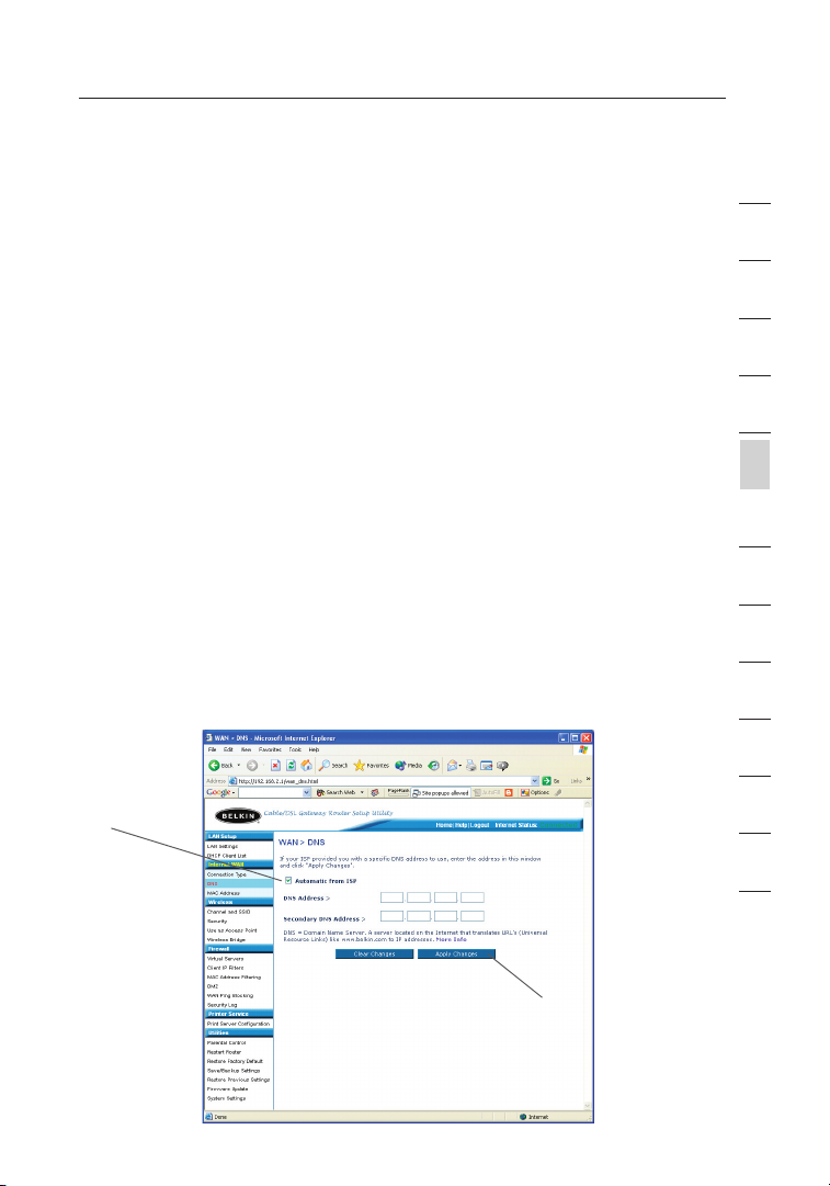
Setting Custom Domain Name Server (DNS) Settings
A “Domain Name Server” is a server located on the Internet that
translates Universal Resource Locater (URLs) like “www.belkin.com”
to IP addresses. Many Internet Service Providers (ISPs) do not require
you to enter this information into the Router. The “Automatic from ISP”
box (1) should be checked if your ISP did not give you a specific DNS
address. If you are using a static IP connection type, then you may
need to enter a specific DNS address and secondary DNS address for
your connection to work properly. If your connection type is dynamic
or PPPoE, it is likely that you do not have to enter a DNS address.
Leave the “Automatic from ISP” box checked. To enter the DNS address
settings, uncheck the “Automatic from ISP” box and enter your DNS
entries in the spaces provided. Click “Apply Changes” (2) to save
the settings.
(1)
1
2
3
4
5
sect ion
6
7
8
9
10
11
12
49
13
(2)

Alternate Setup Method
Alternate Setup Method
51
sect ion
2
1
3
4
5
6
7
8
9
10
11
12
13
Configuring your WAN Media Access Controller
(MAC) Address
All network componen ts incl ud ing c ards , adapt er s, an d routers, have
a unique “serial number” called a MAC addres s. Your Internet Se rvice
Pro vider may reco rd the MAC a ddre ss of your comput er ’s adapter and
only let that particular compute r conne ct to the Inter net s er vice. When
you install the Router, its own M AC ad dres s wil l be “seen” by the
ISP and m ay ca use t he co nn ection not t o w or k. Be lk in ha s provided
the ability to clone (copy) the M AC ad dres s of the computer into the
Router. This MAC address, i n t ur n, will be se en by th e ISP’s sy stem as
the original MAC address an d w il l a ll ow th e con ne ct ion t o w or k. If you
are no t sure whether your ISP needs to s ee th e ori gi na l M AC ad dress,
simply clone the MAC addres s o f the comput er th at was origi na ll y
connecte d to the modem. Cloning the address will no t c au se an y
pro blems with y our n etwork.
50

Alternate Setup Method
Cloning your MAC Address
To clo ne yo ur MAC address, make sure th at yo u are using the c omputer
that was ORIGINALLY CONNECTED to your m odem before th e Route r
was installed. Click the “Clone” button (1). Clic k “Appl y Cha ng es ” (3).
Your M AC ad dress is now cloned to t he Ro ut er.
Entering a Specific MAC Address
In certain circ umstances you may need a sp ec ific WAN MAC addre ss.
You ca n man ua ll y e nt er on e in the “MAC Address” page. Type in a
MAC address i n the spac es provided (2) and click “Apply Changes ” (3)
to save t he ch anges. The R outer’s WAN MA C a dd ress will now be
changed to the MAC ad dres s you spec if ie d.
(2)
(1)
(3)
1
2
3
4
5
sect ion
6
7
8
9
10
11
12
51
13
Using the Web-Based Advanced User Interface
Using the Web-Based Advanced User Interface
53
sect ion
2
1
3
4
5
6
7
8
9
10
11
12
13
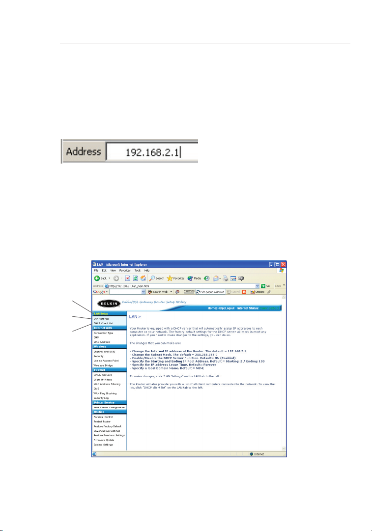
Using your Inter ne t b rowser, you can access the Router’s Web -B ased
Advanced User Interf ac e. In your browser, type “192.168.2 .1 ” ( do
not type in an ything else such as “h tt p://” o r “ ww w” ) t he n p ress the
“Enter” key.
You wi ll se e the Router ’s home pa ge in yo ur browser window.
Viewing the LAN Settings
Clicking on the header of the L AN ta b (1) will take you t o the LAN
tab’s hea de r p ag e. A quick descri pt ion o f the func ti on s c an be
found here. To view the settings or make c hanges to an y o f the LAN
settings , click on “LAN Settings ” (2) or to view t he li st of conn ec ted
computer s, clic k on “DHCP Client List” (3).
(1)
(2)
(3)
52
Using the Web-Based Advanced User Interface
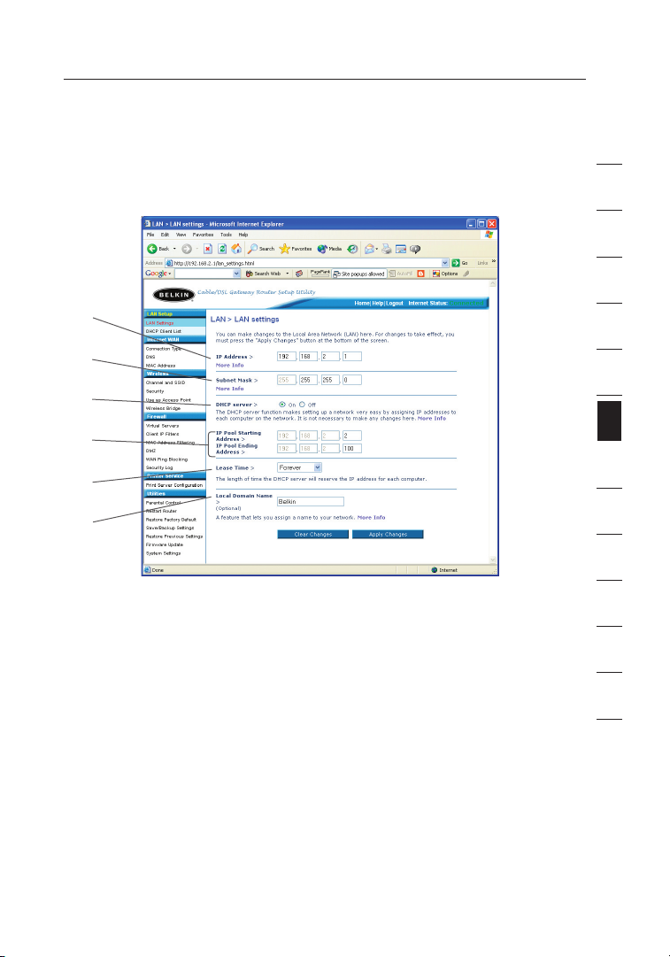
Changing LAN Settings
All settings for the interna l LAN setup of the Router can be vi ewed
and changed here.
(1)
(2)
(3)
(4)
(5)
(6)
1. IP Address
The “IP a ddre ss ” i s the internal IP ad dres s of the Router. The
default IP address i s “ 19 2. 168.2.1”. To a cc es s t he ad va nc ed
setup interface , typ e this IP address i nto t he ad dres s bar of your
bro wser. This addre ss ca n be chang ed if needed . To ch ange the
IP addre ss, t yp e i n the new IP address a nd cl ic k “ Ap pl y C ha nges”.
The IP ad dres s you choo se shou ld be a non-routable IP.
Examples of a non-ro utable IP are:
192.168. x. x (wh ere x is a ny thing between 0 a nd 25 5)
10.x.x.x (where x is an yt hi ng be tween 0 an d 255 )
2. Subnet Mask
There is no need to change the subnet mask. This is a un iq ue ,
advanced feature of your Be lkin Router. It i s p os si ble t o c ha ng e
the subnet mask if ne cessary, how ev er, d o NOT make changes to
the subnet mask unless you have a sp ec ific reas on to do so. The
default setting is “255.255 .2 55.0”.
1
2
3
4
5
6
sect ion
7
8
9
10
11
12
13
53

Using the Web-Based Advanced User Interface
Using the Web-Based Advanced User Interface
55
sect ion
2
1
3
4
5
6
7
8
9
10
11
12
13
3. DHCP Server
The DHCP server function makes setting up a n etwork very easy
by assigning IP addresses t o e ac h c om pu ter o n t he netw or k
automati ca ll y. The default setting is “On”. The DHCP s erver
can be tu rned OFF if n ecessary, ho we ver, in order to do so yo u
must manually set a s tatic IP a dd re ss for each compute r on
your network. To t ur n off the DHCP server, sele ct “O ff” and click
“Apply Changes” .
4. IP Pool
The ran ge o f IP add resses set aside for dynamic ass ignment to the
com puters on your network. The default is 2 –100 (99 computers). If
you wan t to cha nge this number, you can do so by entering a new
sta rting and endin g IP add ress and clicking on “Apply Changes”.
The DHC P se rver can assign 100 IP addresses automatically. T his
mea ns t hat you cannot spec ify an I P ad dress pool la rger than 100
com puters. For exa mple, start ing at 5 0 me ans you have to end at
150 or lowe r so as not to exceed the 100-clien t limit. The starting
IP address must be lower in number t han the ending IP address.
5. Lease Time
The length of time th e D HC P s er ve r w il l reserve the IP address
for each computer. We reco mm en d t ha t y ou leav e the lease
time set to “F orev er ”. Th e def au lt se tt ing i s “ Fo reve r” , mea ni ng
that any time a c om pu ter i s a ss ig ned a n I P address by the
DHCP server, the IP a ddre ss wi ll no t chang e for that partic ul ar
computer. Setti ng le as e tim es fo r short er in te rv als s uch a s one
day or on e h ou r f rees IP addre sses after t he sp ecified period of
time. This also means that a pa rt icular computer’s I P add ress
may change over time. If y ou ha ve se t any of the other advanced
features of t he Ro ut er su ch as DMZ or client IP filters, these are
dependen t on the IP a ddre ss . F or th is reason, you will not want
the IP ad dres s to chang e.
6. Local Domain Name
The default setting is “Belkin”. You can set a local domain name
(network name) for your network. There is no need to change this
setting unless you have a specific advanced need to do so. You can
name the network anything you want such as “MY NETWORK”.
54

Using the Web-Based Advanced User Interface
Viewing the DHCP Client List Page
You ca n vie w a list of t he co mputers (known as c lients), which are
connecte d to your network. You a re able to view the IP ad dress (1) of
the computer, the host name (2) (if the c om puter has be en as signed
one), and the MAC a dd re ss (3) of the computer ’s network interface
card ( NI C). P ress in g the “Ref resh” button will update the list. If there
have been any changes, the list w ill b e u pd at ed.
(1) (2) (3)
1
2
3
4
5
6
sect ion
7
8
9
10
11
12
55
13

Using the Web-Based Advanced User Interface
Using the Web-Based Advanced User Interface
57
sect ion
2
1
3
4
5
6
7
8
9
10
11
12
13
Configuring the Wireless Network Settings
The Wire less ta b l et s y ou make chan ge s to the wireless network
settings . From this tab y ou ca n mak e chang es to the wireless network
name (SSID), operati ng chan ne l, en cr yption security setting s, and
configure the R outer to b e use d as an access point.
Changing the Wireless Network Name (SSID)
To ide nt ify y ou r w ireles s net wo rk , a name called the SSID (Servic e
Set Identifier) is used. The default SSID of the R ou ter i s “ be lk in54g”.
You ca n cha ng e thi s to anythin g you want to or y ou ca n l ea ve it
unchange d. If there are other wireless networks operat in g i n your
are a, yo u w il l wan t to make sure th at yo ur SS ID is unique (doe s not
match that of another wirel ess n etwork in th e a rea). To ch an ge th e
SSID, type in the S SI D t ha t y ou want to use in th e S SI D f ie ld (1) a nd
click “Apply Changes ” (2). The change is immediat e. If you make a
change to the SSID, y our w irel es s-equipped compute rs may also need
to be recon fi gu re d to connect to your new network name. Refer to t he
document at io n o f you r wireless network adapte r for inform at ion o n
making this change.
(1)
56
(2)

Using the Web-Based Advanced User Interface
Using the Wireless Mode Switch
Your R ou ter c an op er ate i n three differe nt wi rele ss mode s: “8 02 .1 1gAuto”, “802.11g -O nly”, a nd “8 02.11g-LRS”. The differe nt mo de s a re
explaine d below.
802.11g-Auto Mode
In this m ode, the R ou ter i s c om pa tible with 8 02.11b and 8 02.11g
wireless clients simultane ou sl y. This is the f ac tory default mode and
ensures successful operati on with all Wi-Fi-c om patible devices. If
you have a m ix of 802.11 b and 802.11 g cli en ts in your networ k, we
rec ommend setting the Router to 802.11g-Auto mode. This settin g
should only be changed if you h av e a spec if ic reason to do s o.
802.11g-Only Mode
802.11g- On ly mo de wo rk s wit h 802 .1 1g cl ie nts o nl y. This mode
is rec om mended only if yo u wan t to prevent 802.11b clients from
accessin g your netwo rk . To switch modes, select the desired
mode fro m t he “Wireless Mode” drop-down box. Then, click
“Apply Changes” .
802.11g-LRS Mode
We recomm en d y ou DO NOT use this mode u nless y ou ha ve a very
specific reason to d o s o. This mode exists only to solve unique
pro blems that m ay oc cur w it h s om e 8 02 .1 1b cl ient ad apters and i s
NOT necessary for interoperabilit y of 802.11g and 802.11b stan da rds.
When to Use 802.11g-LRS Mode
In some c ases, older 802.11b clients may not be co mp atible with
802.11g wireless. These adapters tend to be of in fe rior design and
may use o lder drivers or t echnology. 8 02 .1 1g-LRS (Limited Rate
Support) allows thes e clien ts to be compatib le with the newer
802.11g technol og y. Switching to this mode can solve p ro bl em s t ha t
sometime s occur with these clien ts . If you suspect that you are us in g
a client adapter that falls into this category of ad apters, first check
with the adapter vendor to see if th ere is a d ri ver u pdate. If th ere
is no d ri ver u pdate a vailable, switchin g to 802.11g -L RS mo de ma y
fix your prob le m. Please note that switching to 802.11g-LRS mode may
decrease 802.11g performance slightly.
1
2
3
4
5
6
sect ion
7
8
9
10
11
12
13
57

Using the Web-Based Advanced User Interface
Using the Web-Based Advanced User Interface
59
sect ion
2
1
3
4
5
6
7
8
9
10
11
12
13
Using High-Speed Mode
The Router supports two High-Spe ed mode s, 12 5H SM * m od e a nd
Frame Bursting mode.
Selectin g “125H SM mo de ” wil l result in all d evices running in 1 25HSM
mode if a ll de vices a re capabl e of 125Mbps spee ds . If any
non-125H SM devi ce co nn ec ts or as so ci ates with th e n et work, t he
Router will automati ca ll y s hi ft th e ent ire network back to Frame
Bursting mode.
Selectin g “Fram e Bur st in g” wi ll result in all devices capable of
Frame Bursting to function in Frame Bursting mode, and all clients
not capable, to operate in normal 802.11g modes. Frame Bursting
mode supports both Frame Burstin g- en abled devices and non-Frame
Bursting -e na bled devices simultaneo us ly. Frame Bursting mode is
based on the u nrel ea sed 8 02 .11e specification .
Selectin g “Off” will disable Turbo mode.
*When operating in High-Speed Mode, this Wi-Fi device may achieve an actual throughput
of up to or greater than 34.1Mbps, which is the equivalent throughput of a system following
802.11g protocol and operating at a signaling rate of 125Mbps. Actual throughput will vary
depending on environmental operational and other factors.
58

Using the Web-Based Advanced User Interface
Changing the Wireless Channel
There are a number of o perating channels you can choose from . I n
the United States and Australia, there are 11 channel s. In the United
Kingdom and most of E urop e, th ere are 1 3 cha nn el s. In a small
number of other countries, there are othe r chann el requirements.
Your R ou ter i s con fi gure d to operate on the prop er ch annels for
the country you re si de in . The defa ul t cha nn el is 11 (unles s you are
in a co un try t hat d oe s n ot al lo w cha nn el 11 ). Th e chann el ca n be
changed if needed. If there are other wireless n etworks operating in
your are a, yo ur ne tw ork s ho uld b e s et to operat e on a channel that is
differe nt th an th e other wireless networks . For best perfor ma nc e, us e
a channel that is a t lea st fi ve chan ne ls aw ay from the other wirel ess
network. For instanc e, if anothe r netwo rk is operat in g o n chann el 11,
then set your network to c hannel 6 o r bel ow. To c ha nge t he ch an nel,
select the channel from t he drop-dow n lis t. Clic k “Ap pl y Cha ng es”.
The change is immediate.
1
2
3
4
5
6
sect ion
7
8
9
10
11
12
59
13

Using the Web-Based Advanced User Interface
Using the Web-Based Advanced User Interface
61
sect ion
2
1
3
4
5
6
7
8
9
10
11
12
13
Using the Broadcast SSID Feature
Note: This advanced feature should be employed by advanced users only.
For security, yo u can choo se not to broadcast your network’s S SI D.
Doing so will keep yo ur ne twork n ame h idden f ro m compu te rs th at
are sc an ning fo r t he presence of wireless networks. To tu rn off the
bro adcast of th e S SI D, remove the check mark fro m t he bo x next to
“Broadcast SSID”, and then click “Apply Changes”. The change is
immediat e. Each comp ut er no w nee ds to be set to co nn ect t o y ou r
specific SSID; an SSID of “ANY” w ill n o l on ge r b e accep te d. Re fe r t o
the documentati on of your wireless network adapter for informa ti on
on making this change.
Protected Mode Switch
As part o f t he 80 2. 11 g s pe cification, Protected Mode ensures p rope r
operatio n of 802.11g client s and access poin ts when there is he avy
802.11b traffic in t he op er ating environment. When Pro te cted mo de
is ON, 80 2.11g scans for o ther wi re le ss ne tw ork t ra ff ic befo re it
transmit s data. Therefore, using this mode in en vi ronm en ts wi th
HEAVY 802.11b traffic or i nterference a chieves best performanc e
res ults. If y ou are in an en vi ro nm en t w it h v er y lit tl e—or no —other
wireless network traffic, your be st pe rformance will be a chieved with
Pro tected mode OFF.
60

Using the Web-Based Advanced User Interface
Securing your Wi-Fi® Network
Here a re a few d iffe rent ways you can m aximize the security of
your wireless n etwork and p ro te ct yo ur da ta from prying eyes and
ears. This section is intended for the home, home offi ce , a nd smal l
off ice u ser. At th e tim e of this manual’s p ublication, there are three
encrypti on meth od s a va il able.
Name 64-bit Wired
Equivalent
Privacy
Acron ym 64-bi t WEP 128-b it WEP WPA- TK IP WPA- AE S
Secur it y Good Bette r Best Best
Featu re s Static keys Stati c keys Dynami c key
Encry pt io n
keys based
on R C4
algor it hm
(typi ca ll y
40-bi t keys)
128-bit Wired
Equivalent
Privacy
More secu re
than 64-bit
WEP using a
key length o f
104 bits p lu s
24 a dditional
bits of sy st em
gener at ed
data.
Wi-Fi Protected
Access-TKIP
encry pt io n
and mutual
authe nt ic at ion.
TKIP (tempora l
key integrity
pro to co l)
added so
that keys are
rot at ed a nd
encry pt io n is
stren gt hened.
With Protected
Access
Dynam ic key
encry pt io n
and mutual
authe nt ic at ion.
AES (Ad va nc ed
Encry pt io n
Stand ar d) d oe s
not cause an y
throu gh put
loss.
WEP (Wired Equivalent Privacy)
WEP (Wired Eq ui valent Privacy) is a c om mon p roto co l t ha t add s
security to all Wi-Fi-compl ia nt wi rele ss products. WEP was designed
to give w irel es s n et works t he eq uivalent level of p rivacy prot ection as
a comparable wired n etwork.
1
2
3
4
5
6
sect ion
7
8
9
10
11
12
13
64-Bit WEP
64-bit WEP was first introd uced with 64 -bit encryption, which
includes a key length of 4 0 b it s plu s 24 additio na l bit s of
system-g en er ated data (6 4 b it s t ot al ). So me ha rdwa re
manufact urers refer t o 6 4- bit a s 40- bi t e nc ry ption. Shortly after
the technology was introduced, re search ers f ound th at 64 -bit
encrypti on was too easy
to decode.
61

Using the Web-Based Advanced User Interface
Using the Web-Based Advanced User Interface
63
sect ion
2
1
3
4
5
6
7
8
9
10
11
12
13
128-Bit WEP
As a result of 64-bit WEP’s p ot en tial security weaknesse s, a more
secure m ethod o f 1 28 -bit en cryption was developed. 128-bi t
encrypti on incl ud es a key length of 104 bits plus 24 ad di tional
bits of s ystem-gener at ed da ta (1 28 bits tota l) . Som e hardware
manufact urers refer t o 1 28 -bit as 10 4- bit e nc ryption.
Most of t he ne w w ireles s equip me nt in the marke t today supp or ts
both 64-bit and 128-bit WEP encryption, but you might have
older equipment that only suppor ts 64-b it WE P. All Belkin
wireless pro du cts w il l s up port bo th 64 -bit an d 1 28 -bit WE P.
Encryption Keys
After selecting either the 64-bit or 128-bit WEP encryption mode, it is
critical that you generate an encryption key. If the encryption key is
not consistent throughout the entire wireless network, your wireless
networking devices will be unable to communicate with one another
on your network and you will not be able to successfully communicate
within your network.
You ca n ent er your key by typing in the h ex ke y man ua lly, or you c an
type in a pa ss phrase in th e “ Pa ss phrase” field and c lick “Generate”
to cre at e a key. A hex (hexad ec im al) k ey is a mixture of n um bers and
letters from A– F a nd 0– 9. For 64-bi t WEP, you need to enter 10 hex
keys. For 128-bit WEP, you need to e nter 26 he x key s.
For instance:
AF 0F 4B C3 D4 = 64-bit WEP key
C3 03 0F AF 0F 4B B2 C3 D4 4B C3 D4 E7 = 128-bit WEP key
The WEP p assphrase is NOT the s am e a s a WEP key. Your card uses
this passphrase to generate your WEP keys, but diff eren t hardware
manufact urers might have differe nt me th ods o n g en er ating the ke ys.
If you ha ve mu ltiple vendors’ equipment s in your network , the easiest
thing to do is to use the hex WEP k ey from your Router or access
point and enter it ma nually into the h ex WE P key table in your card’s
configur at io n s creen.
62

Using the Web-Based Advanced User Interface
WPA (Wi-Fi Protected Access)
WPA (Wi-F i Protected Access ) is a new Wi-Fi s tandard t ha t w as
designed to improve upon th e s ec urity f eature s o f WEP. To use W PA
security, t he dr iv ers a nd so ft ware of your wireless equipment must
be upgraded to support WPA. These upda te s wil l be found on the
wireless vendors website. There a re two types of WPA secur it y, WPAPSK (no s erver) and W PA (with radius server).
WPA-PSK (no server) uses wh at is kn ow n as a
Pre -Share d k ey as the Network key. A Netwo rk ke y is basical ly a
password that i s b et ween 8 and 63 characte rs lo ng . It can be a
combinat io n of lette rs , num be rs, o r cha ra cters. Each client uses
the same Network key to ac cess th e n et wo rk. Typ ic al ly, this is the
mode that will be u se d i n a home environment.
WPA (with radius server) is a sy st em wh ere a radius server
distribu te s the Netw or k key to the clients automati ca lly. This is
typicall y found in a business environment.
For a l is t o f Bel ki n wireless products that support WPA, pl ea se vi si t
our website at www.belkin.com/networking.
1
2
3
4
5
6
sect ion
7
8
9
10
11
12
63
13

Using the Web-Based Advanced User Interface
Using the Web-Based Advanced User Interface
65
sect ion
2
1
3
4
5
6
7
8
9
10
11
12
13
Wireless G Router
Wireless G Notebook
Network Car
d
Wireless G Desktop
Network Card
Wireless G Desktop
Network Card
Sharing the Same Network Keys
Most Wi-Fi prod ucts ship wi th se curity turne d off. So on ce yo u hav e
your network working , you need to activate WEP or WPA and make
sure y ou r w ireles s netwo rk ing d ev ices are shari ng the same
Network key.
Network key=
MyPassword
Network key=
MyPassword
The Wire less G Des kt op Ne tw ork C ard canno t acces s the networ k
because it is using a di fferent Network key than the N etwork key t hat
is configured o n t he Wi reless G Router.
Network key=
MyPassword
Network key=
WRONG Password
64

Using the Web-Based Advanced User Interface
Using a Hexadecimal Key
A hexadecimal key is a m ix ture of numbers and letters from A–F a nd
0–9. 64-bit keys are fi ve two- di git n um bers. 128-bit keys are 13
two-digi t numbe rs .
For instance:
AF 0F 4B C3 D4 = 64-bit key
C3 03 0F AF 0F 4B B2 C3 D4 4B C3 D4 E7 = 128-bit key
In the bo xes b elow, ma ke up your key by writing in two ch aracters
between A–F and 0–9 i n e ac h b ox . You will use th is ke y t o program
the encryption setti ng s on your Router and your wireless computers.
Note to Mac users: Origin al Appl e Air Po rt
bit encryption only. Ap ple A ir Port 2 p roduct s can suppor t 64-bi t or
128-bit encrypt io n. Pl ea se ch eck y ou r p roduct to see which version
you are usi ng . If you cannot config ure your network with 128-bit
encrypti on , try 64-b it encr yp tion.
®
p rodu ct s s up po rt 64 -
1
2
3
4
5
6
sect ion
7
8
9
10
11
12
65
13

Using the Web-Based Advanced User Interface
Using the Web-Based Advanced User Interface
67
sect ion
2
1
3
4
5
6
7
8
9
10
11
12
13
WEP Setup
64-Bit WEP Encryption
1 Select “64-bit WEP” from t he drop-d ow n m en u.
2. Aft er se lecting your WEP en cryption mode, you can e nter your
key by ty ping in th e hex key manuall y, or yo u c an type in a
passphra se in the “Passphra se ” f ie ld an d cli ck “Gen er ate” to
cre ate a ke y.
A h ex (h ex adecimal) key is a mix tu re of numbers and letters from
A–F and 0 –9. F or 64 -b it WE P, you need to enter 10 h ex ke ys .
For instance:
AF 0F 4B C3 D4 = 64-bit WEP key
3. Cli ck “A pply Ch anges” to fi nish. Encryption in the Router is no w
set. Each of y our c om puters on yo ur wi rele ss ne tw or k w il l n ow
need to b e c on figure d w it h the same securi ty se tt in gs.
WARNING: If yo u a re configur in g the Wireless Router or Access Point
fro m a comp ut er wi th a wireless client, you will need to en sure that
security is turn ed ON for this wireless client. If t his i s n ot done , you
will lose your wirel ess c on nection.
66

Using the Web-Based Advanced User Interface
128-Bit WEP Encryption
Note to Mac® users: The Passphr as e o pt io n w il l n ot oper at e w it h
Apple® A irPort®. To config ure encryptio n for your Mac computer,
set the e ncryption using the manual method describe d in the
next section.
1. Selec t “12 8- bi t W EP ” f rom the dro p- down menu.
2. After sele ct in g y ou r W EP encr yp tion mo de, y ou ca n ent er yo ur
key manually by typing in the h ex ke y man ua ll y, or you c an ty pe
in a pa ss phrase in th e “ Pa ssphrase” field and click “Generate” to
cre ate a ke y.
A h ex (h ex adecimal) key is a mix tu re of numbers and letters from
A–F and 0 –9. F or 12 8- bit W EP, you need to enter 26 he x k ey s.
For instance:
C3 03 0F AF 0F 4B B2 C3 D4 4B C3 D4 E7 = 128-bit WEP key
1
2
3
4
5
6
sect ion
7
8
9
10
11
12
3. Click “Apply Changes ” to finish. Encryp ti on in the Route r is now
set. Each of y our c om puters on yo ur wi rele ss ne tw or k w il l n ow
need to b e c on figure d w it h the same securi ty se tt in gs.
WARNING: If yo u a re configur in g the Wireless Router or Access Point
fro m a comp ut er wi th a wireless client, you will need to en sure that
security is turn ed ON for this wireless client. If t his i s n ot done , you
will lose your wirel ess c on nection.
67
13

Using the Web-Based Advanced User Interface
Using the Web-Based Advanced User Interface
69
sect ion
2
1
3
4
5
6
7
8
9
10
11
12
13
Changing the Wireless Security Settings
Your R ou ter i s equ ip ped w it h W PA (Wireless P ro te ct ed Ac cess), the
latest wireless security standard. It also su pports the l egacy security
standard, WEP ( Wire d Equ iv alent P rivacy). By default, wireless
security is disabled . To en able security, yo u must first determ in e
which standard you w ant t o use . To access the s ecurity settings, click
“Securit y” on the Wireless tab.
WPA Setup
Note: To use WPA security, a ll yo ur cl ie nts m us t b e upg ra de d t o
drivers and software that s upport it. A t t he ti me of this manual’s
publicat io n, a secur it y pat ch do wn lo ad is av ai la ble, for f ree, from
Microsoft. This patch works only with t he Wi ndows X P o pe rating
system. You a ls o n ee d t o downl oa d t he late st dr iv er fo r you r Belki n
Wireless G De sk top o r N ot eb ook N etwork Card from the Belkin
support site. Other operati ng sy st em s a re not supported at this time.
Microsoft’s pat ch on ly supp or ts de vi ces w ith W PA-enab le d dri ve rs
such as B elkin 802.11g prod ucts.
There are two types of WPA security : WPA-PSK (no s erver) and W PA
(with radius server) . WPA-PSK (no s erver) uses a s o- ca lled PreShared k ey as the secur it y key. A Pre-Shared key is a pas sw ord that
is between 8 a nd 63 char ac ters lo ng. I t c an be a combination of
letters, number s, an d other char ac te rs. E ach c li ent u ses t he sa me key
to access the network. Typi cally, this mode will be used in a hom e
environment.
WPA (with radi us serv er ) i s a configur at io n w he rein a radius server
distribu te s the keys to the clients automati ca ll y. This is typically used
in a bu si ness enviro nment.
Setting WPA-PSK (no server)
1. Fro m t he “S ec ur ity M ode” drop -d ow n m en u, se le ct “W PA-PSK
(no server)”.
2. For En cr yption Tech nique, select “TKIP” or “AES”. This setting
will have to b e i de nt ical on th e cli en ts th at yo u set up.
3. Ent er yo ur pre-sh ared key. Th is ca n be from 8 to 63 character s
and can b e l et ters, n umbers, or s ymbols. This same k ey mu st be
used on a ll of th e clien ts th at you set up. For e xample, your PSK
might be something like: “Smith family netwo rk key” .
68
 Loading...