

Page 1

High-Speed Mode
Wireless G Router
with Built-In USB
Print Server
User Manual
F5D7231-4P
Page 2

Table of Contents
1
2
1
3
4
5
6
7
8
9
10
11
12
sec tion
13
1 Introduction . . . . . . . . . . . . . . . . . . . . . . . . . . . . . . . . . . . . . . . . . . . . 1
Benefits of a Home Network . . . . . . . . . . . . . . . . . . . . . . . . . . . . . .
Advantages of a Wireless Network . . . . . . . . . . . . . . . . . . . . . . . . . 1
Placement of your Wireless G Router . . . . . . . . . . . . . . . . . . . . . . .
2 Product Overview . . . . . . . . . . . . . . . . . . . . . . . . . . . . . . . . . . . . . . . . 6
Product Features . . . . . . . . . . . . . . . . . . . . . . . . . . . . . . . . . . . . . .
3 Knowing your Router . . . . . . . . . . . . . . . . . . . . . . . . . . . . . . . . . . . . .
Package Contents . . . . . . . . . . . . . . . . . . . . . . . . . . . . . . . . . . . . . 9
System Requirements . . . . . . . . . . . . . . . . . . . . . . . . . . . . . . . . . . .
Easy Install Wizard Software System Requirements . . . . . . . . . . . . 9
4 Connecting and Configuring your Router . . . . . . . . . . . . . . . . . . . . . 14
5 Configuring and Using the USB Print Server . . . . . . . . . . . . . . . . . . 22
6 Alternate Setup Method . . . . . . . . . . . . . . . . . . . . . . . . . . . . . . . . . . 34
7 Using the Web-Based Advanced User Interface . . . . . . . . . . . . . . . . 52
Changing LAN Settings . . . . . . . . . . . . . . . . . . . . . . . . . . . . . . . . . 53
Viewing the DHCP Client List Page . . . . . . . . . . . . . . . . . . . . . . . . 55
Configuring the Wireless Network Settings . . . . . . . . . . . . . . . . . . 56
Securing your Wi-Fi Network . . . . . . . . . . . . . . . . . . . . . . . . . . . . 61
WEP Setup . . . . . . . . . . . . . . . . . . . . . . . . . . . . . . . . . . . . . . . 66
WPA Setup . . . . . . . . . . . . . . . . . . . . . . . . . . . . . . . . . . . . . . . 68
Using the Access Point Mode . . . . . . . . . . . . . . . . . . . . . . . . . . . . 76
Wireless Range Extension and Bridging . . . . . . . . . . . . . . . . . . . . 77
Configuring the Firewall . . . . . . . . . . . . . . . . . . . . . . . . . . . . . . . . 81
Setting MAC Address Filtering . . . . . . . . . . . . . . . . . . . . . . . . . . . 84
Enabling the Demilitarized Zone (DMZ) . . . . . . . . . . . . . . . . . . . . . 85
Utilities Tab . . . . . . . . . . . . . . . . . . . . . . . . . . . . . . . . . . . . . . . . . . 87
Restarting the Router . . . . . . . . . . . . . . . . . . . . . . . . . . . . . . . 88
Updating the Firmware . . . . . . . . . . . . . . . . . . . . . . . . . . . . . . 93
8 Manually Configuring Computer Network Settings . . . . . . . . . . . . 101
9 Recommended Web Browser Settings . . . . . . . . . . . . . . . . . . . . . . 107
10 Using your Router with AOL Broadband . . . . . . . . . . . . . . . . . . . . 109
11 Troubleshooting . . . . . . . . . . . . . . . . . . . . . . . . . . . . . . . . . . . . . 120
12 USB Print Server FAQs . . . . . . . . . . . . . . . . . . . . . . . . . . . . . . . . . 140
13 Information . . . . . . . . . . . . . . . . . . . . . . . . . . . . . . . . . . . . . . . . . 141
1
2
6
9
9
Page 3

Introduction
Thank you for purchasing the Belkin High-Speed Mode Wireless G
Router (the Router) with Built-In USB Print Server. Below are two short
sections, one discusses the benefits of home networking, the other
outlines best practices in order to maximize your wireless home network
range and performance. Please be sure to read through this User Manual
completely, and pay special attention to the section entitled “Placement
of your Wireless Networking Hardware for Optimal Performance” on the
next page. By following our simple setup instructions your Belkin Home
Network will allow you to:
• Share one h igh-speed Inte rnet connect io n w it h a ll th e c om puters
in your home
• Share a s in gle p rinter with the entire family
• Share reso urce s, su ch as fi le s, an d h ard drive s a mo ng al l t he
connecte d c om puters in your home
• Share documents, mus ic , v id eo, a nd di gital pictures
• Store, ret ri eve, and copy files from on e c omputer to another
• Simultan eo usly play games online , che ck In te rnet e-m ai l,
and chat
sec tion
1
2
3
4
5
6
7
8
Here are some of the advantages of setting up a
Belkin Wireless Network:
Mobility – you’ll no longer need a dedicated “computer room”— now
you can work on a networked laptop or desktop computer from virtually
anywhere within your wireless range
Easy installation –
Flexibility – set up and access printers, computers, and other
networking devices from anywhere in your home
Easy Expansion – the wide range of Belkin networking products let
you expand your network to include devices such as printers and
gaming consoles
No cabling required – you can spare the expense and hassle of
retrofitting Ethernet cabling throughout the home or office
Widespread industry acceptance – choose from a wide range of
interoperable networking products
Belkin’s Easy Installation Wizard makes setup simple
1
9
10
11
12
13
Page 4

Introduction
Introduction
3
2
1
3
4
5
6
7
8
9
10
11
12
sec tion
13
Placement of your Wireless G Router
Important Factors for Placement and Setup
Your w irel es s c on nection will be stronger the closer your com pu ter
is to y our W irel ess R outer or Access Point. Typical indoo r ope ra ting
range for your wireless device s is bet we en 10 0 a nd 20 0 f ee t. In th e
same way, yo ur wi rele ss co nn ection and perfor ma nce w ill d egrade
somewhat as the dista nc e b et ween your Wireless Router or Access
Point and connec te d d ev ices increases. This may or may not be
noticeab le to yo u. As you mov e fur th er from your Wireless Rout er
or Access Point, conn ec tion speed may decrease. Factor s tha t can
weaken sign al s s im ply b y g et ting in the w ay of yo ur ne twork’s ra di o
waves are m etal appliance s or obstr uc tions, and walls.
If you have concern s a bout your network’s pe rformance that mi gh t b e
rel ated to range or o bstructio n fac to rs, try moving the computer to a
position be tw een f ive a nd te n f eet f ro m the Wireless Rout er or Ac ce ss
Point, in order to se e i f d is tance is t he prob le m. If di ff ic ulties persist
even at close range, pleas e c on tact Belkin Technical Suppor t.
Note: Wh il e s ome o f t he it em s l isted below can aff ect n etwork
performa nc e, they will not p ro hi bit y our wirel ess network from
function in g; if yo u a re concer ned that your networ k is not oper at ing a t
its maximum effectiv en ess, this checklist may help.
1. Wireless Router or Access Point Placement
Place your Wireless Route r or Acces s P oi nt, t he ce ntral
connecti on po int o f y ou r n et work, as close as possible to the
center of your wireless networ k dev ic es.
To ach ie ve the b est w irel ess n etwork coverag e for yo ur “w irel es s
clients” (i .e ., co mputers enable d by Belki n W ireles s N ot ebook
Network Cards, Wireless Deskt op Ne tw ork C ards , a nd Wi rele ss
USB Adapter s) :
• E ns ure tha t you r Wireles s Rou te r’s or Access Poin t’s
networki ng an tennas are p ar allel to e ach other, and are
position ed ve rtically (towa rd the ceiling ). If your Wi reless
Router or Access Poin t its el f i s p os itioned vertic al ly, point the
antennas as much as possib le in an upwa rd direction.
• I n mul ti story homes, place the Wireless Rout er or Acce ss
Point on a f loor that is as cl ose to t he ce nter of the h ome a s
possible . T hi s m ay me an pl ac ing the Wire less Router or Access
Point on an upper floor.
• Try no t to place th e Wireles s Rou te r o r Acc es s P oint near a
cordless 2.4GHz phon e.
2
Page 5

Introduction
2. Avoid Obstacles and Interference
Avo id placing your Wireless Router or Access Po in t n ea r
devices tha t may emit radi o “ no ise,” such as m icro wave ovens.
Dense objec ts th at ca n inh ib it Wire le ss communicati on in clude:
• R ef rigerators
• Wa shers and/or drye rs
• M et al ca binets
• L arge aquarium s
• M et allic-based UV tint ed wi nd ows
If your wireless signal seems weak in some spots , mak e s ure that
objects suc h as these are not blocking the signa l’s path (betwe en
your comput er s a nd Wi rele ss Ro ut er or Ac cess Point).
sec tion
1
2
3
4
5
6
3. Cordless Phones
If the performan ce of your wi reless ne tw ork i s i mp aire d a ft er
attendin g t o the abov e iss ue s, and y ou ha ve a c ordles s p ho ne:
• Try mo vi ng co rd le ss ph ones away from Wi rele ss Ro uters or
Access Poin ts an d you r wireles s- enabled comput er s
• U np lug a nd remo ve th e bat te ry from an y cordles s pho ne
that operat e on the 2.4GHz ba nd (c he ck ma nufacturers
informat io n). If t his f ixes the pro bl em, your phone may
be interfer in g.
• I f you r pho ne su pp orts channel sele ct ion, change the
channel on the phone to the furthe st ch an nel f ro m you r
wireless network. Fo r exa mp le, c hange the phone to channel 1
and move your Wireless Router or Acces s Poi nt to chan ne l 1 1.
See your phone’s us er manual for detailed inst ru ctions.
• I f nec es sary, cons id er sw itching to a 900MHz or 5GHz
cordless phone.
4. Choose the “quietest” channel for your wireless network
In locations where hom es o r offices are close t ogether, such as
apa rtment buildings or office complexes, there m ay be wireless
net works nearby that can conflict with yours.
Use the Site Surv ey capabilities f ound in the Wi reles s LA N Utility
of your wireless adapt er t o locate a ny o ther wireless networks that
are a vailabl e (see you r wi reles s adapter’s manual), and move your
Wireless Rou ter (or Ac cess Point) and compu ters to a chan nel as
far away from other networ ks as poss ible.
3
7
8
9
10
11
12
13
Page 6

Introduction
Introduction
5
2
1
3
4
5
6
7
8
9
10
11
12
sec tion
13
Exp eriment with more t han one of the ava ilable channe ls, in
order to find the c learest c onnection and avo id interference from
nei ghboring cordless phon es o r other wi reless de vices.
For Belkin wireless ne tworkin g products, use the detailed Site
Sur vey and wireless ch annel information includ ed in your
Use r Guide.
These guide li nes s hould allow you to cover the maximum
possible area with your Wireless Router or Acce ss Po in t. Sh ould
you need to cover an even wider area, w e s uggest the Belkin
Wireless Range Exten de r/Access Point .
5. Secure connections, VPNs, and AOL
Secure connection s a re connec ti ons t hat t ypically require a us er
name and password, and are u se d w here se cu rity is im portant.
Secure connection s i nc lude:
• Virtual Pr iv ate N etwork (VPN) connec ti ons, often used to
connect remotely to an office network
• T he “B ri ng Your Own Acces s” progra m f rom Ameri ca On li ne
(AOL), whic h let s you use AOL through broadband provided by
another cab le or DSL servi ce
• M os t o n- line banking websit es
• M an y c om merc ial w ebsites which require a us er name and
password to access your accoun t
Secure connection s c an be inte rr upted by a co mputer’s p ow er
manageme nt se tting, which causes it to “go to sleep.” The
simplest so lu tion to av oid t his is t o s im ply rec on nect by
re- running the VPN or AOL software, or by re- lo gging into
the secure web s ite.
A second alter native is to change your compute r’s power
manageme nt se ttings so it do es not g o t o sle ep ; h owever, this may
not be appropriate for portabl e com pu ters. To cha ng e y our p ower
manageme nt se tting under Windows , see the “Po we r O pt ions” item in
the Control Panel.
If you continue to have difficulty wit h Sec ure Conne ct ion, VPNs and
AOL please review the steps above to be sure y ou ha ve ad dres sed
these issue s.
4
Page 7

Introduction
For more information regarding our networking products, visit our website
at www.belkin.com/networking or call Belkin Technical Support at:
US: 877-736-5771
310-898-1100 ext.2263
Europe: 00 800 223 55 460
Australia: 1800 666 040
sec tion
1
2
3
4
5
6
7
8
9
10
11
12
13
5
Page 8

7
2
1
3
4
5
6
7
8
9
10
11
12
sec tion
13
Product Overview
Product Features
In minutes you will be able to share yo ur Inter ne t c on nection and
network you r com pu ters. The following is a list of features that
make your new Belkin Wireless G Router an ideal solut io n f or yo ur
home or small office network.
Works with Both PCs and Mac® Computers
The Router suppo rt s a vari et y o f n et working environmen ts in cl uding
Mac OS® 8 .x, 9 .x, X v1 0.x, AppleTalk®, Linux®, Windows® 9 5, 98 ,
Me, NT®, 2000, and XP, and others. All that is needed is an Inter net
bro wser and a ne twork adapter that sup po rts T CP/IP (the standard
language of the Inter net).
Front-Panel LED Display
Lighted LED s on the front of the R outer indicate whic h f un ctions
are in op er ation. You’ll know at-a-glan ce wh et her y our Router is
connecte d t o the Inte rnet. This feat ure elimi na tes t he ne ed fo r
advanced so ft ware an d sta tu s-monitor in g p roce du res.
Built-in USB Print Server
Your route r inc lu des a bu ilt-in USB print server tha t let s you prin t t o
a USB p rinter from an y c omputer on the network. The prin t ser ve r
is very simple to setup and conven ie nt to us e. Si mply install your
printer’s drivers and softwa re on each comput er, a nd th en ru n t he
easy to use Print Server Setu p Wiz ard to setup the print serv er. I n
minutes, al l of your compu te rs will have access to the same printer.
NAT IP Address Sharing
Your R ou ter employs Netwo rk Ad dres s Tra ns lation (NAT) to share the
single IP address assigne d to you by your Internet Service Provider
while savin g the cost of addi ng ad di tional IP addresses to your
Internet service accoun t.
6
Page 9

Product Overview
SPI Firewall
Your R ou ter is e quipped with a fire wall that will protect your network
fro m a wi de ar ra y o f c om mon h acker attacks inclu di ng IP Sp oofing,
Land Attack , Pin g of Death (P oD ), De nial of Se rvice (DoS), IP with
zero l ength, Smurf Attack , TCP Null Sc an , S YN fl oo d, UD P f looding,
Tear D rop Attac k, IC MP de fect, RIP defect, and fragm en t f lo oding.
Integrated 10/100 4-Port Switch
The Router has a built-in, 4- po rt ne twork switch to allow your wired
computer s t o sha re printe rs , d at a a nd MP 3 f il es, d igital photos,
and much more. T he sw itch features automatic de te ction so i t w il l
adjust to the speed of connec te d d ev ices. The switch will trans fe r
data betwee n com pu ters and t he Inter ne t s im ultaneous ly wi th out
interrup ti ng or co nsuming resources.
Universal Plug-and-Play (UPnP) Compatibility
UPnP (Unive rs al Pl ug-and-Pl ay ) i s a techno lo gy that offe rs se amless
operatio n o f voi ce me ss aging, video messag in g, games, and other
applicat io ns that are UPn P- compliant .
Support for VPN Pass-Through
If you connect to your office network from home using a VPN
connecti on , y our R outer will allow your VPN-e qu ipped computer to
pass through the Router and to your office network.
Built-In Dynamic Host Configuration Protocol (DHCP)
Built-In Dy na mic H ost C onfigurat io n P roto co l ( DH CP) o n-board m akes
for the easiest possi bl e c on nection of a network. The DHCP serv er
will assign IP addresses to each compu te r a ut omaticall y so there is
no need for a c omplicated net wo rking setup.
1
sec tion
2
3
4
5
6
7
8
9
10
11
12
13
Easy Install Wizard
The Easy Install Wiza rd takes the gues sw ork o ut of se tt ing up y our
Router. Thi s aut om atic software determine s you r net wo rk settings for
you and sets up the Router for connecti on to yo ur In te rnet Servi ce
Provider (ISP). In a matter of minutes, your Wireless Router will be up and
running on the Internet. A separate wizard is included for setup of the print
server.
7
Page 10

Product Overview Knowing Your Router
NOTE: Easy Install Wizard software is compatible with Windows 98SE, Me,
2000, XP and Mac OS 9.X and Mac OS X. The Print Server Setup Wizard
software is compatible with Windows 98SE, Me, 2000, and XP. If you are
using another operating system, the Wireless Router can be set up using the
Alternative Method described in this manual (see page 34).
Integrated 802.11g Wireless Access Point
802.11g is an exciting new wireless technology that achieves data rates up to
54Mbps in 54G Mode, nearly five times faster than 802.11b.
125 High-Speed Mode
High-Speed Mode (HSM)*, a 54g™ performance enhancement, provides
the fastest wireless connectivity for 802.11g-capable networks in real-world
environments. It is designed for home networks that require additional
bandwidth for applications such as sharing digital pictures. 125HSM makes
802.11g WLANs more efficient without impacting the performance of
neighboring networks, and is compatible at high speeds with leading brands.
Integrated Parental Control Web Content Filter
Belkin has teamed with Cerberian, a leading content-filtering company, to
bring you this unique feature. Your Belkin Wireless G Router is the first home
networking solution with an integrated web content filter that allows you to
block unwanted or offensive web content before it makes it to your network.
Unlike other Parental Control solutions, Parental Control is built into the Belkin
Wireless Router, so there is no software to install on any computer and you
will never be charged a per-computer fee for the service, ever. Your Wireless
Router comes with a six-month free trial of this feature so you can take
advantage of the capabilities right away. No credit card is needed to use the
trial. You have control: Belkin Parental Control can be modified to meet your
needs. You can set up your own policies and block any website you want.
There is also an optional reporting feature (fee-based) that allows you to get a
report showing you every website that was visited from your network (refer to
your Parental Control Manual for more information).
MAC Address Filtering
For added security, you can set up a list of MAC addresses (unique client
identifiers) that are allowed access to your network. Every computer has its
own MAC address. Simply enter these MAC addresses into a list using the
web-based user interface and you can control access to your network.
*When operating in High-Speed Mode, this Wi-Fi device may achieve an actual throughput
of up to or greater than 34.1Mbps, which is the equivalent throughput of a system following
802.11g protocol and operating at a signaling rate of 125Mbps. Actual throughput will vary
depending on environmental, operational and other factors.
8
Page 11

Package Contents
• Belkin High-Speed Mode Wireless G Router with Built-In USB
Print Serverr
• Quick Installation Guide
• Belkin Easy Install Wizard Software CD
• Belkin RJ45 Ethernet Networking Cable
• Power Supply
• User Manual
System Requirements
• Broadband Internet connection such as a cable or DSL modem with
RJ45 (Ethernet) connection
• At least one computer with an installed network interface adapter
• TCP/IP networking protocol installed on each computer
• RJ45 Ethernet networking cable
• Internet browser
1
2
sec tion
3
4
5
6
7
8
9
Easy Install Wizard Software System Requirements
• A PC running Windows 98SE, Me, 2000, or XP or a Mac computer
running Mac OS 9.x or OS X
• Minimum 64MB RAM
• Internet Browser
Print Server Setup Wizard System Requirements
• A PC running Windows 98SE, Me, 2000, or XP
• Minimum 64MB RAM
9
10
11
12
13
Page 12

Knowing Your Router
Knowing Your Router
11
sec tion
2
1
3
4
5
6
7
8
9
10
11
12
13
The Router has been design ed to be plac ed on a deskt op . A ll of th e
cables exit from the re ar of th e Rou te r f or be tt er organi za tion and
utility. The L ED in dicators are easily visibl e on the front of the R outer
to pro vide you w ith i nformatio n abo ut ne twork activity and statu s.
(1) (2) (3) (4) (5)
2.4GHz • High-Speed Wireless G
1. Power/Ready/Print Activity LED
When you apply power to the Router or restart it, a short period
of time elapses while the Rou te r b oo ts up . D ur ing this time, the
LED blinks. When the Router has completely booted up , t he
Power/Re ad y L ED be comes a SO LID light, indica ti ng th e R ou ter
is rea dy fo r u se . W he n d ata i s b ei ng se nt to th e p ri nter, the light
will blink fast.
OFF Router is OFF
Slow B linking Gre en Router is Booting Up
Solid Green Router is Ready
Fast Blinki ng Green Printer Act iv ity
2. WLAN: Wireless Network LED
OFF Wireless Network is OFF
Gre en Wireless Network is Ready
Blinking Indi cates Wireless Activity
3. LAN Port-Status LEDs
These LEDs are l abeled 1–4 and correspond to the numbered
ports on the rea r o f t he Ro ut er. W hen a co mputer is prop erly
connecte d t o one of the LAN ports on the rear o f t he Ro ut er, the
LED will light. GREEN mean s a 10Ba se -T de vice is connected,
ORANGE mean s a 100Bas e- T d ev ice is c onnected. When
informat io n i s b ei ng se nt ov er the p ort, the L ED blinks rapidly.
10
Page 13

Knowing Your Router
OFF No Device is Linked to the Port
Gre en 10Base-T De vi ce Co nnected
Orange 100Base- Tx De vice Connected
Blinking
(Orange or Green)
4. WAN Status LED
This LED lights in GREEN to indica te th at yo ur mo dem i s
connecte d p roperl y t o the Rout er. I t b li nks r apidly when
informat io n i s b ei ng se nt ov er the p ort b etween the Router and
the modem.
OFF No WAN Link
Solid Green Good WAN Li nk
Blinking Green WAN Activit y
5. Connected LED
This unique LED shows you whe n the Rout er is co nn ected to t he
Internet. When the light is OFF, th e Rou te r i s N OT co nn ected to
the Inter net. When the light is blinking, the Route r i s att em pting
to connect to the Internet. When the light is solid GREEN, the
Router is connec te d t o the In te rnet. When usin g the “D is connect
after x minutes” feat ure, this LED bec om es ex trem ely u seful in
monitori ng th e s ta tus o f y ou r R outer’s co nn ection.
OFF Router is not Connect ed to th e Int er net
Blinking Green Router is Attemp ti ng to Co nn ect to t he
Solid Green Router is Connec te d t o the In te rnet
Port Activi ty
Internet
1
2
sec tion
3
4
5
6
7
8
9
10
11
12
13
11
Page 14

Knowing Your Router
Knowing Your Router
13
sec tion
2
1
3
4
5
6
7
8
9
10
11
12
13
(6) (7) (8) (9)(10)
6. Power Jack - GRAY
Connect the incl ud ed 5V DC po we r s up ply t o t hi s j ack.
7. Connections to Computers (LAN Ports) - BLUE
Connect you r wired (non-w irel es s) co mputers to these ports.
These ports are RJ45, 10/100 auto-n eg otiation, auto -u plinking
ports for standa rd UTP categor y 5 or 6 Ether ne t c able. The ports
are la beled 1 th ro ug h 4 . The se po rts c orre spond to t he nu mbered
LEDs on the fron t o f t he Ro ut er.
8. Connection to Modem (WAN Port) - GREEN
This port is for connectio n t o you r cab le or DS L mod em . U se th e
cable that was provided with the modem to connec t the mo de m
to this port. Use of a ca ble o ther than the cable supplie d wit h t he
cable modem may not work properly.
9. Reset Button
The Reset button is used in rare c ases when the Router may
function im proper ly. Resett in g t he Ro ut er wi ll rest ore the Rout er ’s
normal oper at ion w hile maintaini ng th e program me d s et tings. You
can also re store t he fa ct ory d efault setting s b y usi ng th e Res et
button. Use the restore o ption in instances whe re you may have
forgo tten your custom passw ord.
a. Resetting the Router
Push and re lease the Reset button. The ligh ts on the Rou te r
will moment ar ily f lash. The Power/Rea dy li gh t w ill b egin to
blink. When the Power /R eady light becomes sol id ag ai n, th e
res et is co mplete.
12
Page 15

Knowing Your Router
b. Restoring the Factory Defaults
Pre ss and h old t he Re set button for at least ten seconds
then release it. The lights on the Router will moment ar ily
flash. The Power /R eady light will begin to blink. When the
Power/Re ad y l ight becomes solid again , the restore
is complete .
10. USB Port - PURPLE
For USB printers only. See the s ection called “Conn ec ting your
printer to Route r’s print server” on page 22.
1
2
sec tion
3
4
5
6
7
8
9
10
11
12
13
13
Page 16

Connecting and Configuring Your Router
Connecting and Configuring Your Router
15
sec tion
2
1
3
4
5
6
7
8
9
10
11
12
13
Verify the contents of your box. You should have the following:
• Belkin High -S peed Mode Wire less G R ou ter
• Quick Insta ll ation Guide
• Belkin Easy Inst al l W iz ard Sof tw are CD
• RJ45 Ethernet Networkin g Cab le (f or co nnection of the
Router to the compute r)
• Power Suppl y
• User Manual
Modem Requirements
Your c ab le or DS L m od em mu st be eq uipped with an RJ45 Ether net
port. Many modem s hav e bot h a n RJ4 5 Eth er net port and a USB
connecti on . I f y ou ha ve a mod em wi th bo th Et he rnet and USB, and
are us ing t he US B c on nection at this time, you will be instru ct ed to
use the RJ45 Ethern et port during the installa ti on proc ed ure. If your
modem has only a USB port, you can re qu est a di ff erent typ e of
modem from your ISP, or you c an, in s ome c ases, purchase a modem
that has an RJ45 Ether net p ort o n i t.
Ethernet USB
ALWAYS INSTALL YOUR ROUTER FIRST! IF YOU ARE INSTALLING
NUMEROUS NETWORK DEVICES FOR THE FIRST TIME, IT IS
IMPORTANT THAT YOUR ROUTER IS CONNECTED AND RUNNING
BEFORE ATTEMPTING TO INSTALL OTHER NETWORK COMPONENTS
SUCH AS NOTEBOOK CARDS AND DESKTOP CARDS.
Easy Install Wizard
Belkin has provided our Easy Instal l W iz ard sof tw are to make
installi ng yo ur Ro uter a s im ple and easy task. You ca n use it to get
your Router up and running in minu te s.
The Easy Install Wiza rd requires t hat y our Windows® 98SE , Me,
2000, XP or Mac OS 9 .2x, X.1.x computer be conn ec ted d irec tly t o
your cable or DSL modem and that the Inter net connecti on is acti ve
14
Page 17

Connecting and Configuring Your Router
and working at the time of install at ion. If it is no t, yo u mus t u se th e
“Alter nate Setup Method ” sec ti on of th is ma nual to co nfigure y our
Router. Add it ionally, i f you are using an operatin g sys te m o th er than
Windows 98S E, Me , 200 0, or XP, you mu st se t up the Rout er us in g
the “Alternate Setup Method” sect io n o f t hi s m an ual.
IMPORTANT: R un th e E as y I nstall Wizard software from th e
computer th at is directly conn ec ted t o t he ca ble o r D SL mo dem.
DO NOT CONNECT THE ROUTER AT THIS TIME.
Step 1 Run the Easy Install Wizard Software
1. Shut do wn an y program s tha t are running on your compu te r a t
this time.
2. Make sure y ou ha ve th e f ollowing items at the compute r t ha t i s
now directly connect ed to the cable or DSL modem . DO NOT
CONNECT THE ROUT ER AT THIS TI ME .
• Quick Installa ti on Gu ide
• The E asy I nstall Wizard CD-ROM
• The R outer
• The R outer power supply
• RJ45 Ether ne t n et working cable
• This User Manual
3. Turn off any firewall or Internet connect io n s ha ring software on
your comput er.
4. Inser t t he Ea sy In st all W izard s of tware C D i nt o y ou r C D– ROM
drive. The Insta ll ation Menu will automati ca lly appear on your
screen within 15 seconds. If it does not, select your CD -R OM
drive from “My C omputer” and double -c lick on the f ile n amed
“Start.e xe ” o n t he CD -R OM.
1
2
3
sec tion
4
5
6
7
8
9
10
11
12
13
15
Page 18

Connecting and Configuring Your Router
Connecting and Configuring Your Router
17
sec tion
2
1
3
4
5
6
7
8
9
10
11
12
13
5. Clic k “ Ru n R ou ter S etup Wizard”.
Welcome Screen
The Wizard’s wel co me sc re en wi ll
appear. Mak e sure you have not
connecte d t he Ro ut er at th is po int.
If you have connected your Ro ut er,
please reconnect you r com pu ter
directly to the modem. Click “Next”
when you are ready to move on.
Progress Screen
Easy Instal l wil l sho w you a progress
screen each time a st ep in th e s et up
has been complet ed . E ac h t im e y ou se e
the progre ss sc reen , c li ck “N ext” when
you are ready to move to the next step.
16
Page 19

Connecting and Configuring Your Router
Examining Settings
The Wizard will now e xamine your
computer ’s network sett in gs an d
gather info rm ation needed to complete
the Router’s c onnection to the
Internet. When the Wizard is fi nished
examinin g y ou r c om puter, click “Next”
to continue .
Multi-NICs Screen
If you have more th an on e n et work adapter instal le d i n y ou r c om puter
a Multi-NIC Screen will appear. If you have more than one network
adapter ins ta lled in yo ur co mputer, the Wizard will need to know
which adapt er is conn ec ted t o y our m odem. Select the network ca rd
that is connecte d to your mod em from the list and click “Next ”. If you
are no t s ure which adap te r t o c ho ose, select the adapter at the top of
the list. If you mistakenl y c ho ose t he wron g ada pt er no w, y ou wi ll be
able to choose a diff eren t o ne la ter.
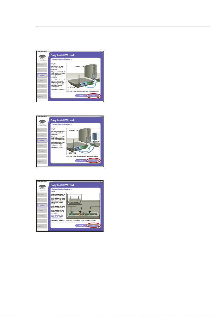
Step 2 Hardware Setup
The Wizard will walk you throu gh connecting you r Rou te r t o you r
computer an d mod em . F ol low t he steps on t he sc re en us in g t he
pictures as a gu ide.
2.1 T hi s s te p i nstructs you to locate
the cable connec te d b et ween your
modem and the network in g p or t o n
your comput er. U np lug t his c able
fro m t he co mputer and plug it into
the GREEN port on the Router.
Click “Next ” to conti nu e.
1
2
3
sec tion
4
5
6
7
8
9
10
11
12
13
17
Page 20
Connecting and Configuring Your Router
Connecting and Configuring Your Router
19
sec tion
2
1
3
4
5
6
7
8
9
10
11
12
13
2.2 T hi s s te p i nstructs you to locate
the BLUE cable that is includ ed
with your Router. Plu g one en d
of this cable into ANY one of the
BLUE ports on your Router. Pl ug
the other end of the cable into the
networki ng po rt on yo ur co mp uter.
Click “Next ” to conti nu e.
2.3 T hi s s te p i nstructs you to locate
the power supply that is incl ud ed
with your Router. Plu g the po we r
supply’s small connecto r int o the
GRAY po rt on the Rou te r. Pl ug th e
power suppl y int o an empty po we r
outlet. Cli ck “N ex t” to co nt inue.
2.4 T hi s s te p i nstructs you to look
at the lights on the fro nt of yo ur
Router. Mak e sure the appropriate
lights are ON. R efer to the E asy
Install sof tw are on your compu te r’s
screen for more de ta ils. Click
“Next” to contin ue .
18
Page 21

Connecting and Configuring Your Router
Step 3 Checking the Connection
1
2
3.1 O nc e y ou ha ve co mpleted
connecti ng th e R ou ter, the W izard
will check the connec ti on to th e
Router and then go on to determine
what type of Intern et connection
you have.
3.2 User Name and Password Needed
If you have a connection type that
requires a user name and a password,
the Wizard will ask you to type in
your user name and password. If your
connection type does not require a
user name and password, you will not
see this screen.
Your user name and password is
provided to you by your Internet
Service Provider. If you have to type
in a user name and password to
connect to the Internet, then type that
same user name and password in
here. Your user name looks something
like “jsmith@myisp.com” or simply
“jsmith”. The service name is optional
and is very rarely required by your ISP.
If you don’t know your service name,
leave this blank. When you have
entered your information, click “Next”
to move on.
3
sec tion
4
5
6
7
8
9
10
11
12
13
19
Page 22
Connecting and Configuring Your Router
Connecting and Configuring Your Router
21
sec tion
2
1
3
4
5
6
7
8
9
10
11
12
13
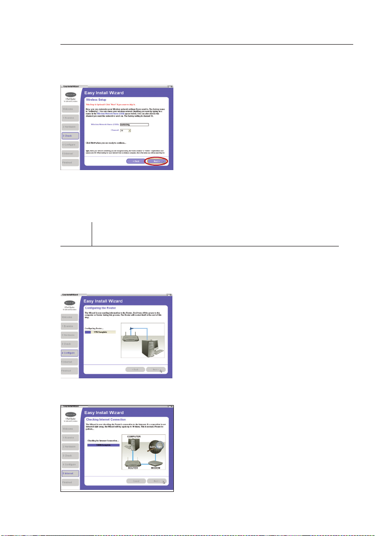
3.3 Wireless Setup
This Step Is Optional. Click “Next” if
you want to skip it.
Using this step, you can cust om ize
your wireless networ k set ti ngs i f
you want to. Follow the steps on
the screen to co mplete this step.
Click “Next ” to conti nu e.
Step 4 Configuring the Router
The Wiza rd w il l now tra ns fer all o f the configu ra tion info rm ation to th e
Router. Th is will t ak e approximate ly one minute . During th is time, do
not turn off the Ro ut er or com pu ter. The Ro uter will resta rt itself a t the
end of t hi s step.
4.1 Checking Internet
The Wizard will now c heck for an
Internet connectio n. Th is ca n tak e
a few m inutes. The Wizard may not
detect a connect io n r ig ht aw ay. If
not, it will ret ry a n um ber o f t im es.
The “Connec te d” li ght o n t he front
panel of the Router will flas h dur in g
this time. Pleas e be patie nt th roug h
this process.
20
Page 23

Connecting and Configuring Your Router
4.2 Finished
When the Inter net c onnection
is complete , the Wiza rd will tell
you that you are fi ni shed. The
“Connect ed ” L ED on th e front of
the Router will be solid GREE N,
indicati ng th at th e R ou ter i s n ow
connecte d t o the Inte rnet.
Your Router is now conn ec ted to the In terne t. Now you ca n begin
surfing th e Inter net by open in g your browser an d going to yo ur favorite
web page .
Congratulations! You have fini sh ed installi ng your new B elkin Rou te r.
You are rea dy to set u p the other c omputers in your hom e. You c an
also add c omputers to your Rou te r any tim e you want.
1
2
3
sec tion
4
5
6
7
8
9
10
11
12
21
13
Page 24
Configuring and Using the USB Print Server
Configuring and Using the USB Print Server
23
sec tion
2
1
3
4
5
6
7
8
9
10
11
12
13
Connecting your printer to the Router’s print server
Please closely follow the directions to set up your printer.
Before you start
Install the printer’s drivers and software on each computer from which you
plan to print. This enables the PC to print to the networked printer (printer
that is attached to your USB Print Server). Every manufacturer ships its
printer with a driver and, usually, printing software. In some cases, while
installing the drivers and software for your printer, you may be required to
connect the PC directly to the printer in order to complete the installation.
This varies according to manufacturer. You must also install the Belkin Printer
Port on each of the computers you want to print from. This may be done
using the Printer Server Setup Wizard, or can be done manually.
Start
1. Insert the CD into your CD-RO M dri ve . W it hin 1 5 s econds, you
should see the instal la tion menu on the s cree n. If th e m en u
does not appear withi n 15 sec on ds, s elect your CD-ROM drive
and view the contents of the drive . Dou bl e-click on the file
named “Star t. exe”.
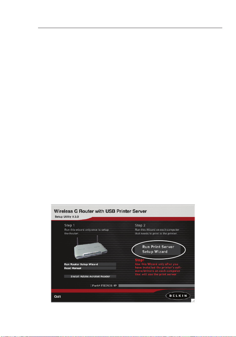
2. Fro m t he me nu, c lick on “Run Print Server Setup Wizard”. This
will open the Print Server Se tu p W iz ard men u.
22
Page 25

Configuring and Using the USB Print Server
3. On the Wizard me nu, d rag your mouse over the “Run Wizard”
button and click the words “Click Here” to start the Wizard.
4. The first screen of t he Wizard ap pears. Be sure th at yo u h av e
installe d y ou r p ri nter’s dri ve rs an d s oftware o n t he PC s from
which you plan to print. Clic k “Ne xt ”.
1
2
3
4
sec tion
5
6
7
8
9
10
11
12
23
13
Page 26

Configuring and Using the USB Print Server
Configuring and Using the USB Print Server
25
sec tion
2
1
3
4
5
6
7
8
9
10
11
12
13
5. Next, make sure the R outer is ON. Make sure th e p ri nter is ON .
Plug in the USB cable that is connected to the print er to the USB
port on the re ar of th e Rou te r. Th e U SB po rt on th e Rou te r i s
color-cod ed pu rp le. C lick “Next”.
6. The Wizard will scan for and locate the Print Server in the Router.
Next, a list of the printers insta ll ed on th e c om puter will appear.
Click once on the name of the printer that is connec te d t o the
Router to highli gh t i t. Cl ic k “ Next”.
24
Page 27
Configuring and Using the USB Print Server
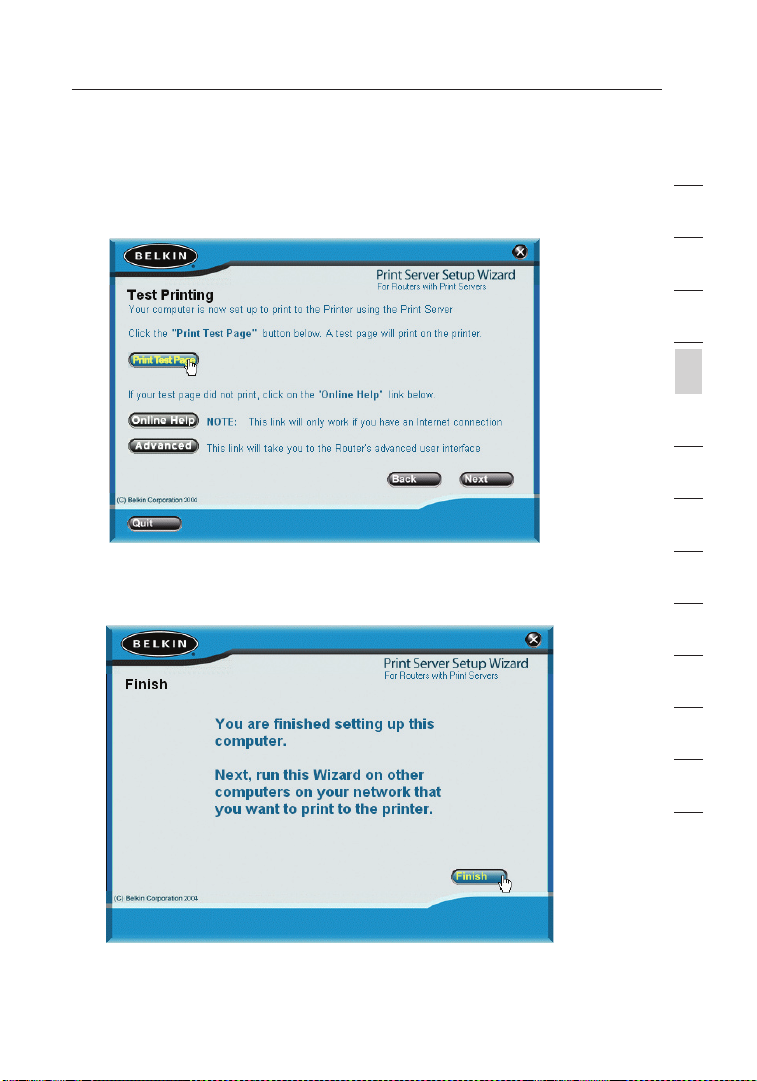
7. The next screen that appears will allo w you to test prin t. Cl ic k
on the “Print Test Pa ge” b utton. When your test page is finis he d
printing , c li ck “N ext”.
8. You are now finish ed se tt ing u p y ou r c omputer to print to the
Print Serve r. Ne xt , r un th is Wi zard on the other comp ut ers on
your networ k from which you wish to print to this printe r.
1
2
3
4
sec tion
5
6
7
8
9
10
11
12
25
13
Page 28

Configuring and Using the USB Print Server
Configuring and Using the USB Print Server
27
sec tion
2
1
3
4
5
6
7
8
9
10
11
12
13
Manually installing the print server port
Advanced users can manually install the Belkin Printer Port without using the
Wizard. To do this, from the Installer menu, click “Install Printer Port Only” to
skip the Wizard. Belkin has also included a standalone installer on the CD.
From the CD, double-click on the file called “instportA.exe”.
Configuring Computers to Print to the Print Server
1. Install Pri nt er Po rt So ftware on ea ch co mputer by running
“instpor tA .exe” fro m t he CD or by usin g the Wiza rd.
2. Configure the Belkin Port Moni to r o n e ac h c om puter’s pr in ter
driver to point to the Router ’s Print Server as follow s:
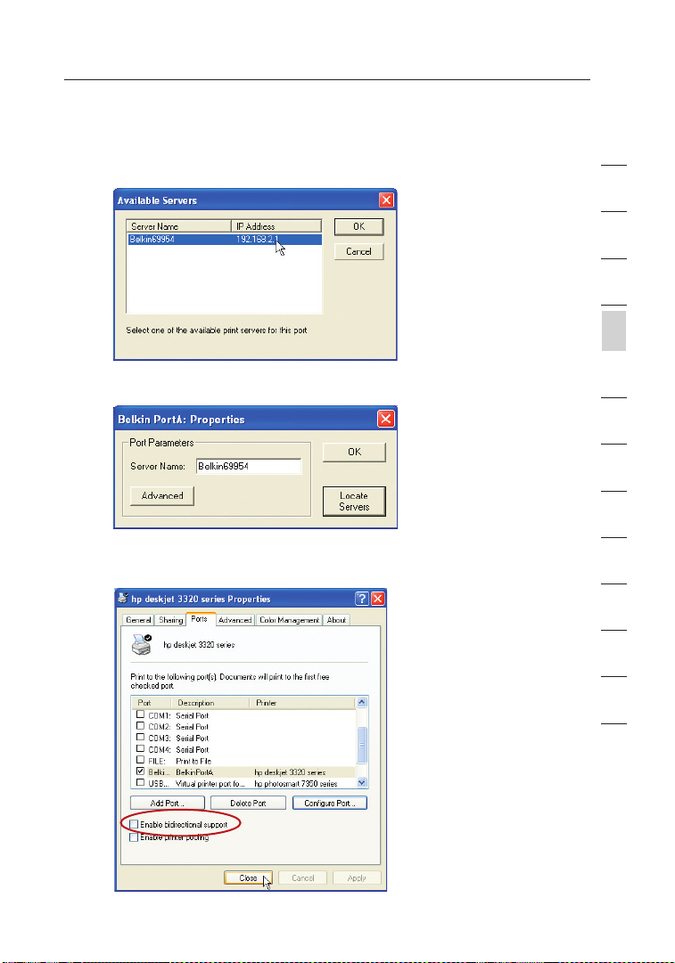
a. In Windo ws , s el ect t he pr inter’s proper ti es for t he pr inter
connecte d t o the Prin t Ser ve r a nd se lect the “ Port” tab,
select the Belki n por t, an d c li ck “C onfigure Port...”
b. On the “Belkin PortA: Properties” window, click “Locate Servers”.
26
Page 29
Configuring and Using the USB Print Server
c. On th e “Availa bl e S er vers” window, your Router ’s print server
name will appear. Sel ec t t he Pr int S erver. Click “OK” to close.
d. On th e “Be lk in Port A: Prop er ties” window, the name of the
Print Serve r wil l app ea r. Cl ick “OK” to c lose.
e. On the P orts tab, uncheck the box next to “Enabl e bid irec ti onal
support” if currentl y che ck ed. C lick “Apply”.
1
2
3
4
sec tion
5
6
7
8
9
10
11
12
f. Click “Close” to clos e the wind ow.
27
13
Page 30

Configuring and Using the USB Print Server
Configuring and Using the USB Print Server
29
sec tion
2
1
3
4
5
6
7
8
9
10
11
12
13
Uninstalling the print server port
1. In Windows, sele ct th e pri nt er’s propertie s f or th e pri nt er co nnected to
the Print Server and selec t t he “P or t” ta b, se lect the Belkin port, and click
“Configu re Port.. .” .
2. Select a different p ort f ro m the list of avai la ble p orts. You mu st se le ct a
differe nt po rt before yo u c an remove the Belki n p or t.
3. Fro m t he In staller menu, click “Rem ov e P rinter Port” to uninstal l the
printer por t. Be lk in ha s a ls o p rovi de d a n u ni nstaller appli ca tion that will
rem ove the Belkin printer port from the PC. Fro m t he CD , d ou ble-click on
the file called “rmvp or tA.exe”. This will remove the printe r por t.
28
Page 31

Configuring and Using the USB Print Server
Using the Print Server
Print Server Configuration Screen
For proper operation of the Print Server, install the printer’s drivers and
software on each computer from which you plan to print. The Belkin Print
Server Port must also be installed on each of these computers. See page 26
of this manual for more information and instructions.
The Print Server Configuration screen is the central point in the Router where
you can find the printer status (ready/not ready) and make certain adjustments.
See page 52 in this manual for directions to access the Advanced Web Based
User Interface.
(1)
(2)
(3)
(4)
(5)
1
2
3
4
sec tion
5
6
7
8
9
10
11
12
Printer field (1)
This line shows you the name of the printer that is connected to the Print
Server and its status.
Print Server Name (2)
The Print Server name identifies the Print Server. If you wish, you can
change it by typing in a new name such as “My Print Server” then clicking
“Apply Changes”.
29
13
Page 32

Configuring and Using the USB Print Server
Configuring and Using the USB Print Server
31
sec tion
2
1
3
4
5
6
7
8
9
10
11
12
13
LPR Printing (3)
The Belkin Printer Port uses LPR as the main printing method.
Raw TCP/IP Printing (4)
This feature allows clients to print to the Print Server using the standard TCP/IP printer
port built into Windows XP and 2000, instead of the Belkin Port Monitor. Using Raw
Printing requires that you configure all port parameters manually. It is not recommended
for users unfamiliar with TCP/IP printing.
FTP Printing (5)
This feature enables the printer to receive print jobs sent by FTP (see “Using FTP Printing”
on this page). Disabling this feature will prevent FTP jobs from printing
Using FTP Printing
This section describes how to send print jobs to the printer using FTP.
1. In Windows, sele ct th e pri nt er’s propertie s.
30
Page 33

Configuring and Using the USB Print Server
2. Set the printer port to “File ”, cl ic k “ Ap ply”.
3. Print the docume nt us in g t he pr inter that you configured. A
dialogue bo x wil l ope n prompti ng yo u t o nam e the prin t f il e.
After namin g the file , cli ck “O K”. A fi le wi ll be sa ve d t o the us er ’s
default Win do ws di re ct ory ( typically “C:\ ” or “C:\D oc uments and
Settings \< user’s n am e>”).
1
2
3
4
sec tion
5
6
7
8
9
10
11
12
31
13
Page 34

Configuring and Using the USB Print Server
Configuring and Using the USB Print Server
33
sec tion
2
1
3
4
5
6
7
8
9
10
11
12
13
4. On the Windows deskto p, cl ic k “ Start>Run” and type in “cmd” for
Windows XP and 2000 or “comma nd ” f or Wi nd ows 9 8SE and Me;
click “OK” to open a “Command /M S-DOS Pro mpt” window.
5. At the prom pt , t yp e “ ft p” fo llowed by the I P a dd re ss of the Route r
(default is 192. 16 8.2.1); press the “ Enter” key to cre ate a n F TP
connecti on wi th th e P ri nt Se rver.
6. When the connect ion i s m ad e, th e u ser w ill b e p romp te d t o
enter a user name and a p assword. The u ser name for the P rint
Server is “anony mo us”; the p assword s hould be left blank. After
a successfu l log in , a list of the print er s c on nected to the Print
Server will appe ar, f ol lowed by simple usage instr uc tions for how
to print the file.
32
Page 35

Configuring and Using the USB Print Server
7. At the prom pt, t ype “ put”, followed by the file path and file
name, follo we d b y the prin te r n umber (for example, “put c:
\example pr in ter1”).
8. The file will be sent to the P rint Server. When the trans fe r i s
complete , a no ther prom pt wi ll ap pear. If finished, typ e “qu it ” a nd
pre ss “Enter” to end the FTP session. Then, clos e the “C om mand
Pro mpt” window.
Note: FTP Printing by default is enabled in the Print Server. It can be
disabled using the Router’s Web-Based Setup Interface. See page 29
for details.
1
2
3
4
sec tion
5
6
7
8
9
10
11
12
33
13
Page 36

Alternate Setup Method
Alternate Setup Method
35
sec tion
2
1
3
4
5
6
7
8
9
10
11
12
13
The Advance d Use r Int er face is a w eb -based tool that you can use to
set up the R outer if you don’t w an t t o u se th e Eas y Ins ta ll Wizard . You
can also use it to m anage advanced func ti ons o f t he Ro uter. Fro m t he
Advanced Us er In te rface, you can perform the follo wi ng ta sks:
• Vie w t he Ro uter’s cur rent sett in gs an d s tatus.
• Configure the Router to connec t to you r ISP with the set ti ngs t hat
they provided you.
• Change the current networ k set ti ngs s uch as t he In terna l IP
address, the IP address p ool, DHCP settings and more.
• Set the Router’s fi re wa ll to wo rk wi th sp ecific applica ti ons
(port forwa rding) .
• Set up security featu res such as clien t restric ti ons, MAC a ddre ss
filterin g, WE P a nd WPA.
• Enable the DMZ feature for a single compute r on your net wo rk.
• Change the Route r’s intern al password.
• Enable/D is able UPnP (Univer sa l P lu g-and-Pla y) .
• Reset the Router.
• Back up your configur at ion s ettings.
• Reset the Router ’s default settin gs .
• Update the Route r’s firmware.
Step 1 Connecting your Router
1.1 Turn o ff the power to your mode m by unp lu gging the power
supply from the modem.
1.2 Loca te th e n et work cable that is connecte d bet we en yo ur mo dem
and your compute r and unpl ug it from your comput er, l ea ving the
other end connec te d t o you r m od em.
1.3 Plu g the loos e end of the cable you jus t unp lu gged into the gre en
port on the back of the R outer labeled “Conn ec tion to Modem”.
1.4 C on nect the new blue network cable (incl ud ed) fro m t he ba ck of
the compute r to one of the blue ports labele d “ 1– 4”. Note: It do es
not matter which numb ered port you cho os e.
34
Page 37

Alternate Setup Method
1.5 Tur n your cable or DSL modem on by re co nnecting the power
supply to the modem.
Mac or PC computer that was originally
connected to the cable or DSL modem
To Power Adapter
Existing networking cable
Note: Your Router ma y hav e por ts in di fferent locatio ns th an
1.6 B ef ore plu gg ing t he power cord i nt o t he Ro ut er, plug the cord
1.7 Veri fy th at yo ur mo dem i s c onnected to the Router by checki ng
1.8 Verify that your co mp uter is co nnected properly to the Router
Network cable
(to computer)
depicted in the illus tr ation above.
into the wall, then plug the cord into the Router’s po wer j ack.
the lights on the fro nt of th e R ou ter. The gre en li ght l abeled
“WA N” sh ould be ON if yo ur mo de m i s c on nected correctly to the
Router. If it is not, re check your connecti on s.
by checking the light s lab el ed “LAN 1,2,3,4”. The light whic h
corresponds to the numbered port connec te d t o y ou r c om puter
should be ON, if your compute r is conne ct ed prop er ly. If it is n ot,
rec heck your connect io ns.
(came with modem)
1
2
3
4
5
sec tion
6
7
8
9
10
11
12
13
35
Page 38

Alternate Setup Method
Alternate Setup Method
37
sec tion
2
1
3
4
5
6
7
8
9
10
11
12
13
Step 2 Set your Computer’s Network Settings to Work
with a DHCP Server
See the section in this manua l cal le d “ Ma nually Configu ri ng Ne twork
Settings ” f or di rect io ns.
Step 3 Configuring the Router Using the Web-Based
Advanced User Interface
Using your Inter net bro wser, you can access the Router’s Web-Based
Advanced Us er In te rface. In your brow ser, type “192.16 8. 2.1” (you do
not need to type in anything else such as “http :/ /” or “w ww ”). T hen
pre ss the “ Enter” key.
PLEASE NOTE: If you have difficulty acc es sing the R outer’s we b-
based inter fa ce, g o t o Sec ti on 7 o f the user ma nu al ti tled “Manually
Configur in g C omputer Networ k Set ti ngs”.
Logging into the Router
You wi ll se e t he Ro ut er’s home pag e in your browser window. The
home page is visible to any user who wants to see it. To mak e a ny
changes to the Router ’s settings, yo u hav e to log in. Click in g t he
“Login” but to n o r cli ck ing o n a ny on e o f the li nk s o n the home pa ge
will take you to the login screen. The Router ships with no passwo rd
entered. In the login screen, leave the password blank and click the
“Submit” bu tt on to lo g in.
36
Page 39

Alternate Setup Method
Logging out of the Router
One compute r at a time can log in to t he Ro uter for the purposes
of making change s to the sett in gs of th e Rou te r. Once a u se r h as
logged in to make changes, th ere are t wo wa ys th at the c omputer
can be logged out. Clickin g t he “L og out” button will log the compute r
out. The second metho d is aut om atic. The login will time out after a
specifie d p er iod o f t im e. Th e d efault login time out is 10 minutes. This
can be changed from 1 to 99 minu te s. Fo r m ore inf or mation, see the
section in this manua l tit le d “ Changing the Login Timeo ut Se tt ing”.
Understanding the Web-Based Advanced User Interface
The home page is the first page you will see when you access the
Advanced Us er In te rface (UI). The home page shows you a quick view
of the Router’s s ta tus and settings. All advan ce d s et up pages can be
rea ched from th is pa ge.
(10) (2) (5) (4) (3)
(6)
(1)
(7)
1
2
3
4
5
sec tion
6
7
8
9
10
11
12
(9)
1. Quick-Navigation Links
You ca n g o directl y to any of the Router’s a dvanced UI pages by
clicking di rectly on thes e lin ks . T he li nks a re divi de d i nt o l og ical
categori es an d g roup ed by tabs to make find in g a part ic ular
setting eas ie r t o fin d. Cl ic king on the p urple header of each tab
will show you a short descrip ti on of th e tab ’s functio n.
(8)
37
13
Page 40

Alternate Setup Method
Alternate Setup Method
39
sec tion
2
1
3
4
5
6
7
8
9
10
11
12
13
(10) (2) (5) (4) (3)
(1)
(7)
(9)
2. Home Button
The home button is availab le in ev er y p ag e o f t he UI . Pressin g
this button will take you bac k to the home page .
3. Internet Status Indicator
This indica to r i s vis ib le in al l p ag es of th e R ou ter, indicatin g
the connect io n s ta tus o f t he Ro uter. When the indicator says
“connect io n O K” in GR EE N, th e R outer is c onnected to the
Internet. When the Router is not connecte d to the Inte rnet, the
indicato r w il l read “no connec ti on” i n R ED. T he in dicator is
automati ca lly updated when you make change s t o the sett in gs of
the Router.
4. Login/Logout Button
This button enab le s y ou to lo g in and out of the Router with the
pre ss of on e b ut ton. When you are lo gg ed in to th e R outer, this
button will chan ge to read “Logout” . L og ging into the R outer will
take you to a s eparate login page where you will need to enter a
password. When you are lo gged in to th e R ou ter, you can make
changes to the settin gs . W he n y ou are finis he d m ak ing c hanges,
you can log out of t he Ro uter by clicking the “Logou t” bu tt on. F or
more i nformation abo ut lo gg ing i nto t he Router, see the section
called “Log gi ng in to th e R ou ter”.
(8)
(6)
38
Page 41

Alternate Setup Method
5. Help Button
The “Help” butto n giv es yo u a cc ess t o t he Ro ut er’s hel p pag es .
Help is also availabl e on man y pag es by clic ki ng “more i nf o” ne xt
to certain secti on s o f eac h p ag e.
6. LAN Settings
Shows you the setting s of the Loca l Area Network (LAN ) s id e o f
the Router. Chan ge s c an be ma de to the setti ng s b y c li cking on
any one of t he links (IP Address, Subnet Mask, DHCP Serv er ) o r
by clicking the “LAN” Quic k N av igation link on the left side of
the screen.
7. Features
Shows the status of the Route r’s NAT, f irew al l, an d w irel es s
features. Changes ca n be made to the settin gs by clic ki ng on an y
one of the l inks or by cl icking the “Quick Navi ga tion” links on the
left side of the scre en.
8. Internet Settings
Shows the settin gs of the Int er net/WAN side of the Router that
connects to the Inter net. Changes to any of these sett in gs ca n
be made by c licking on the links or by clicking on the “Internet/
WAN ” Q ui ck Na vigation link on the left side of the screen.
9. Version Info
Shows the firmwa re versio n, bo ot -code version, hardware
version, an d ser ia l n um ber o f t he Ro uter.
10. Page Name
The page you are on ca n be ident if ied b y t his n ame. This manual
will someti me s refer to pages by name. For insta nc e “ LA N > LA N
Settings ” refers to the “LAN Settin gs ” p age.
1
2
3
4
5
sec tion
6
7
8
9
10
11
12
39
13
Page 42

Alternate Setup Method
Alternate Setup Method
41
sec tion
2
1
3
4
5
6
7
8
9
10
11
12
13
Step 4 Configuring your Router for Connection to your Internet
Service Provider (ISP)
The “Internet/WAN” t ab is wh ere you will set up your Route r to
connect to your Inter net Service Provider (IS P) . T he Ro ut er is ca pable
of connecti ng to virt ua lly a ny ISP’s syst em provid ed yo u hav e
correctly configu red the Rout er ’s setting s for your IS P’s connecti on
type. Your ISP c onnection sett in gs are provided to you by your ISP.
To con fi gure th e R ou ter w ith t he se ttings that your ISP gave you,
click “Conn ec tion Type ” (A) on the left sid e of the screen. Select
the connect io n t yp e y ou us e. If yo ur IS P gav e y ou DN S set ti ngs,
clicking “D NS ” (B) al lows you t o e nt er DNS a ddre ss en tries for ISPs
that require sp ecific setting s. Cl ic king “MAC address” (C) will let you
clone your compu te r’s MAC address or type in a sp ecific WA N MAC
address, if req uire d b y you r ISP. W he n y ou ha ve fi nished making
settings , t he “I nt ernet Stat us ” i nd icator will read “connecti on OK ” if
your Router is set up properly.
(A)
(B)
(C)
40
Page 43

Alternate Setup Method
Setting your Connection Type
From the connection type page, you can select the type of connection you
use. Select the type of connection you use by clicking the button (1) next
to your connection type and then clicking “Next” (2).
(1)
1
2
3
4
5
sec tion
6
7
8
9
10
(2)
11
12
41
13
Page 44

Alternate Setup Method
Alternate Setup Method
43
sec tion
2
1
3
4
5
6
7
8
9
10
11
12
13
Setting your Internet Service Provider (ISP) Connection Type
to Dynamic IP
A dynamic connec ti on ty pe is th e m os t c om mon c onnection type
found with cable mode ms . S et ting the connecti on ty pe to “dyn am ic”
in many cases is enough to complet e the conn ec tion to your ISP.
Some dynami c con ne ction types may req uire a hos t nam e. You can
enter your host name in the space provided if you were a ssigned one.
Your h os t n ame i s a ss igned by your ISP. Some dynami c con ne ctions
may re quire t ha t y ou cl on e t he MA C a dd re ss of the PC that was
original ly co nnected to the modem.
(1)
(2)
(3)
1. Host Name
This space is provided to enter a host name that needs to be
visible to your ISP. Ent er yo ur ho st na me he re and click “App ly
Changes” (3). If yo ur IS P did not ass ig n y ou a host nam e, or you
are no t s ure, leav e thi s bla nk .
2. Change WAN MAC Address
If your ISP re qu ires a speci fi c M AC ad dres s t o con ne ct to th e
service, yo u can ente r a spec if ic MA C a dd re ss or clon e t he
current computer’s MAC address t hrou gh th is li nk.
42
Page 45

Alternate Setup Method
Setting your Internet Service Provider (ISP) Connection Type
to Static IP
A static IP address connection type is less common than other connection
types. If your ISP uses static IP addressing, you will need your IP address,
subnet mask, and ISP gateway address. This information is available from
your ISP or on the paperwork that your ISP left with you. Type in your
information, then click “Apply Changes” (5). After you apply the changes,
the Internet Status indicator will read “connection OK” if your Router is set
up properly.
(1)
(2)
(3)
(4)
(5)
1
2
3
4
5
sec tion
6
7
8
9
10
11
12
1. IP Address
Pro vided by your ISP. Enter your IP address here.
2. Subnet Mask
Pro vided by your ISP. Enter your subne t mas k here.
3. ISP Gateway Address
Pro vided by your ISP. Enter the ISP gateway address here.
4. My ISP Provides More Than One Static IP Address
If your ISP assigns you more than one s tatic IP address, your
Router is capabl e of handl in g u p t o fiv e sta ti c WAN IP addresses.
Select “My ISP provides more t han one static IP address” and
enter your addit io nal a ddre sses.
43
13
Page 46

Alternate Setup Method
Alternate Setup Method
45
sec tion
2
1
3
4
5
6
7
8
9
10
11
12
13
Setting your ISP connection type to PPPoE
Most DSL providers use PPPoE as the connect io n t yp e. If yo u u se a
DSL modem to connect to the Internet, your ISP may use PPPoE to
log you into the service. If you have an Internet connectio n in your
home or small office that doesn’t req ui re a modem , you may also use
PPPoE.
(1)
(2)
(3)
(4)
(5)
Your connection type is PPPoE if:
a) Your I SP ga ve yo u a user na me an d pas sw ord whi ch is required to
connect to the Internet
b) Your I SP ga ve yo u s of tware s uc h a s W in POET or En terne t3 00 th at
you use to c onnect to the Intern et
or
c) You ha ve to do ub le-click on a desktop Icon other than your
bro wser to get o n t he In terne t
(6)
44
Page 47

Alternate Setup Method
1. User Name
This space is provided to type in your User name that was
assigned by your ISP.
2. Password
Type i n y ou r p as sword a nd re-typ e it into the “Ret yp e P as sword”
box to confirm it.
3. Service Name
A Service name is rarely req ui re d by an ISP. If you are no t s ure if
your ISP re quires a ser vi ce na me, leave this blank.
4. MTU
The MTU setting shoul d nev er be ch an ged u nless your ISP gives
you a s pecific MTU setting . M ak ing c hanges to the MTU setting
can cause problems with your Internet connect io n i nc luding
disconne ct ion fro m t he In te rnet, slow Inte rnet acces s and
pro blems with Internet applicati on s w or king prop erly.
5. Disconnect after X...
The Disconn ec t f ea ture is used to auto ma tically discon ne ct th e
rou ter fro m y ou r I SP wh en th ere is no activit y for a speci fi ed
period of time. For instan ce , p lacing a c heckmark next to this
option and enter in g 5 into th e min ut e f ie ld wi ll cause the ro ut er
to disconne ct from the Inter net after 5 m inutes of no Inter ne t
activity. This option should be used if you pay for your Inter net
service by the minute .
1
2
3
4
5
sec tion
6
7
8
9
10
11
12
45
13
Page 48

Alternate Setup Method
Alternate Setup Method
47
sec tion
2
1
3
4
5
6
7
8
9
10
11
12
13
Setting your Internet Service Provider (ISP) Connection Type to
Point-to-Point Tunneling Protocol (PPTP)
[European Countri es On ly]. Some ISPs re qu ire a connec ti on using
PPTP protocol, a type of connection mo st co mm on in Eu rope an
countrie s. Th is se ts up a direct conne ct ion t o t he IS P’s system . Type
in the informati on provid ed by your IS P in the space provided. Wh en
you have finishe d, cl ic k “ Ap ply Changes” (9). After you apply the
changes, th e Int er net Status indi ca tor will rea d “ co nnection OK” if
your Router is set up properly.
(1)
(2)
(3)
(4)
(5)
(6)
(7)
(8)
(9)
1. PPTP Account
Pro vided by your ISP. Enter your PPTP accou nt na me he re.
2. PPTP Password
Type i n y ou r p as sword a nd retype it into the “Rety pe Pa ss word ”
box to confirm it.
3. Host Name
Pro vided by your ISP. Enter your host name here.
46
Page 49

Alternate Setup Method
4. Service IP Address
Pro vided by your ISP. Enter your servi ce IP address here.
5. My IP Address
Pro vided by your ISP. Enter the IP address here .
6. My Subnet Mask
Pro vided by your ISP. Enter the IP address here .
7. Connection ID (optional)
Pro vided by your ISP. If your ISP did not give you a co nnection
ID, leave this blank.
8. Disconnect after X….
The Disconn ec t f ea ture is used to auto ma tically discon ne ct th e
Router from your ISP when there i s n o act iv ity f or a s pe cified
period of time. For instan ce , p lacing a c heck mark next to this
option and enter in g “ 5” in to th e m in ute f ield will cause the Router
to disconne ct from the Inter net after five minutes of no Internet
activity. This option should be used if you pay for your Inter net
service by the minute .
1
2
3
4
5
sec tion
6
7
8
9
10
11
12
47
13
Page 50

Alternate Setup Method
Alternate Setup Method
49
sec tion
2
1
3
4
5
6
7
8
9
10
11
12
13
Setting your Connection Type if you are a Telstra® BigPond User
[Austral ia On ly] Your use r nam e and pass wo rd are prov ided to you b y
Telstra BigPond. Enter th is in fo rmation below. Choos in g y ou r s ta te
fro m t he drop -d own m enu (1) will automatic al ly fi ll in yo ur lo gin s erver
IP address. If y our l ogin server address is differe nt th an on e p rovi de d
here, you m ay ma nually enter the login serv er IP address by placi ng a
check in the box next to “User decide login ser ve r m an ually” (4) and
type in the address n ext to “ Login Server” (5). Whe n you have ente red
all of your informati on , c li ck “Apply Changes ” (7). Aft er yo u a pp ly th e
changes, th e Int er net Status indi ca tor will rea d “ co nnection OK” if
your Router is set up properly.
(1)
(2)
(3)
(4)
(5)
(7)
1. Select your State
Select your stat e from the dro p-down menu (1). The “Login
Server” box will auto ma tically be filled in with an IP address.
If for some re as on th is addres s d oes n ot ma tch t he addres s
that Telstra has given, you can manually en te r t he lo gi n s er ver
address. See “User Decide Logi n Ser ve r M anually” (4).
2. User Name
Pro vided by your ISP. Type i n y ou r u se r n am e h ere.
48
Page 51

Alternate Setup Method
3. Password
Type i n y ou r p as sword a nd retype it into the “Rety pe Pa ss word ”
box to confirm it.
4. User Decide Login Server Manually
If your login server IP address is not available in the “Sele ct Your
State” drop-down men u (1), you may man ua lly e nter the l ogin
server IP address by placing a check in the box next to “ User
decide logi n ser ve r m an ually” and type in the address n ext to
“Login Serv er ” (5).
Setting Custom Domain Name Server (DNS) Settings
A “Domain Name Server” is a server located on the Internet that
translates Universal Resource Locater (URLs) like “www.belkin.com”
to IP addresses. Many Internet Service Providers (ISPs) do not require
you to enter this information into the Router. The “Automatic from ISP”
box (1) should be checked if your ISP did not give you a specific DNS
address. If you are using a static IP connection type, then you may
need to enter a specific DNS address and secondary DNS address for
your connection to work properly. If your connection type is dynamic
or PPPoE, it is likely that you do not have to enter a DNS address.
Leave the “Automatic from ISP” box checked. To enter the DNS address
settings, uncheck the “Automatic from ISP” box and enter your DNS
entries in the spaces provided. Click “Apply Changes” (2) to save
the settings.
(1)
1
2
3
4
5
sec tion
6
7
8
9
10
11
12
49
13
(2)
Page 52

Alternate Setup Method
Alternate Setup Method
51
sec tion
2
1
3
4
5
6
7
8
9
10
11
12
13
Configuring your WAN Media Access Controller
(MAC) Address
All network comp on ents including cards, adapte rs , a nd router s, ha ve
a unique “serial numb er ” c al led a MA C a dd re ss . Your Inter net Service
Pro vider may re cord th e MAC address of your compu te r’s adapte r and
only let that particu la r c om puter connect to the Internet service. Whe n
you install the Route r, it s o wn MA C add ress will be “see n” by the
ISP and may cause the connect io n n ot to work . B el kin h as prov id ed
the ability to clone (copy ) t he MA C add ress of the compu te r i nt o t he
Router. Thi s MAC address, in turn, w ill b e s ee n b y t he IS P’s system as
the origina l MAC address and will allo w the conn ec tion to work. If y ou
are no t s ure wheth er yo ur IS P n ee ds to se e the or ig inal MAC a ddre ss,
simply clon e the MAC address of the compute r tha t was or ig inally
connecte d t o the mode m. Cl on ing the address w ill n ot ca use any
pro blems with your networ k.
50
Page 53

Alternate Setup Method
Cloning your MAC Address
To clo ne yo ur MA C a dd re ss , m ak e s ure that you are using the computer
that was ORIGINA LLY CONNE CT ED to yo ur mo de m b efore t he Ro ut er
was install ed . C li ck th e “ Cl one” button (1). Click “App ly Ch anges” (3).
Your M AC ad dres s i s now clon ed to th e Rou te r.
Entering a Specific MAC Address
In certain circumsta nc es yo u m ay ne ed a spe ci fic WAN MAC address.
You ca n m an ually enter one in the “MAC Address” page. Type i n a
MAC address in t he sp aces prov ided (2) and click “Apply Chan ge s” (3)
to save the changes. The Rout er ’s WA N MAC ad dress wil l now be
changed to the MAC address you specifi ed .
(2)
(1)
(3)
1
2
3
4
5
sec tion
6
7
8
9
10
11
12
51
13
Page 54

Using the Web-Based Advanced User Interface
Using the Web-Based Advanced User Interface
53
sec tion
2
1
3
4
5
6
7
8
9
10
11
12
13
Using your Inter net bro wser, you can access the Router’s Web-Based
Advanced Us er In te rface. In your brow ser, type “192.16 8. 2.1” (do
not type in anything else suc h as “http :/ /” or “w ww”) then pres s t he
“Enter” key.
You wi ll se e t he Ro ut er’s home pag e in your browser window.
Viewing the LAN Settings
Clicking on the heade r of the LAN tab (1) w ill take you to th e L AN
tab’s h ea der p age. A q uick descripti on of the funct io ns can b e
found here. To vie w the sett in gs or ma ke ch anges to a ny of th e L AN
settings , c li ck on “L AN Se tt ings” (2) or to view the l ist o f c onnected
computer s, cl ick o n “ DH CP Cl ient List” (3).
(1)
(2)
(3)
52
Page 55

Using the Web-Based Advanced User Interface
Changing LAN Settings
All setting s for the inter nal LAN setup of the Router can be viewed
and changed here.
(1)
(2)
(3)
(4)
(5)
(6)
1. IP Address
The “IP address” is t he inter na l I P add ress of the Route r. Th e
default IP address is “192.168 .2 .1”. To acce ss th e a dv anced
setup inter fa ce, t ype t his I P a ddre ss in to th e a dd re ss ba r of you r
bro wser. This address can be c hanged if needed. To c hange the
IP address, type in t he new I P a dd re ss an d cli ck “A pply Changes”.
The IP address y ou ch oose should be a n on-routable IP.
Examples of a non-routabl e IP are:
192.168. x. x ( where x is anythi ng be tw een 0 an d 2 55 )
10.x.x.x (w he re x is anything betwe en 0 and 255)
2. Subnet Mask
There is no ne ed to ch an ge th e s ub net m ask. This is a u ni que,
advanced fe at ure of your Belki n Rou te r. It is po ss ible to change
the subnet mask if necessa ry, howeve r, do NOT make changes to
the subnet mask unles s you ha ve a speci fi c reaso n to do so. The
default set ti ng is “2 55 .255.255. 0” .
1
2
3
4
5
6
sec tion
7
8
9
10
11
12
13
53
Page 56

Using the Web-Based Advanced User Interface
Using the Web-Based Advanced User Interface
55
sec tion
2
1
3
4
5
6
7
8
9
10
11
12
13
3. DHCP Server
The DHCP server funct io n m ak es setting up a ne twork very easy
by assignin g IP addresses to each comp ut er on th e net wo rk
automati ca lly. The defa ul t s et ting is “On”. The DHCP server
can be turne d OFF if nece ss ary, howev er, i n o rder to do so you
must manual ly se t a static IP address for each comput er on
your networ k. To turn off the DHCP server, selec t “Off” and click
“Apply Chan ge s”.
4. IP Pool
The range of IP addresses set aside for dynamic as signmen t to the
com puters on your networ k. T he d efault is 2–100 (99 compu ters). If
you want to chang e this number, you can do so by entering a new
sta rting and ending IP address and c licking on “Apply Cha nges”.
The DHCP server c an assign 100 IP addres ses automatic ally. This
mea ns that you ca nnot specify an IP address pool l arg er t han 100
com puters. For examp le, starting at 50 means you have to end a t
150 or lower so as not to ex ceed the 100-clie nt limit. The starting
IP address must be lower in number than the ending IP address.
5. Lease Time
The length of time the DHCP server will reserve the IP address
for each compute r. We re commend that you leave the lease
time set to “Forever”. The default set ti ng is “F orev er ”, me aning
that any time a computer is assign ed an IP address by the
DHCP server, the IP address will not change for that par ti cular
computer. S et ting lease times for shorter int er vals such as on e
day or one h our fre es IP ad dres se s a ft er th e s pe cified period of
time. This also means that a parti cu lar c omputer’s IP ad dres s
may change over time. If you have set any of the other advance d
features of the Router such as DMZ or c lient IP filters, thes e are
dependen t o n the IP address. For this reason, you will not want
the IP address t o c ha nge.
6. Local Domain Name
The default setting is “Belkin”. You can set a local domain name
(network name) for your network. There is no need to change this
setting unless you have a specific advanced need to do so. You can
name the network anything you want such as “MY NETWORK”.
54
Page 57

Using the Web-Based Advanced User Interface
Viewing the DHCP Client List Page
You ca n v ie w a list of the compu te rs (k nown as clients), whic h are
connecte d t o you r net wo rk. You are able to view the I P a ddre ss (1) o f
the compute r, th e hos t nam e (2) (i f the co mp uter has b een a ssigned
one), and the MAC address (3) of t he computer’s n etwork interfa ce
card ( NIC). Pre ssing the “Refresh” button will update th e lis t. If there
have been any changes , the li st wi ll be upda te d.
(1) (2) (3)
1
2
3
4
5
6
sec tion
7
8
9
10
11
12
55
13
Page 58

Using the Web-Based Advanced User Interface
Using the Web-Based Advanced User Interface
57
sec tion
2
1
3
4
5
6
7
8
9
10
11
12
13
Configuring the Wireless Network Settings
The Wireless tab lets you make changes to the wireless network
settings . F rom this tab you can make change s to the wireless netw or k
name (SSID) , ope ra ting channel, encry pt ion s ecurity settin gs , a nd
configure the Router to be used as an a ccess point.
Changing the Wireless Network Name (SSID)
To ide nt ify your wireless network, a name called the SSID (Ser vi ce
Set Identif ie r) is us ed . T he de fault SSID of t he Router is “belkin54 g” .
You ca n c ha nge t his t o a ny thing you want to or you c an le ave i t
unchange d. If th ere are o ther wire less networks opera ti ng in yo ur
are a, you w ill w ant t o m ake s ure tha t you r SSI D i s uni qu e ( do es no t
match that of another wireless netw or k i n t he area). To c hange the
SSID, type in the SSID that you want to use in t he SSID field (1) and
click “Appl y Cha ng es” (2). The change is immediate . If you make a
change to the SSID, your wireless-e qu ipped computer s m ay al so ne ed
to be rec on figured t o c on nect to your new n etwork name. Refer to the
document at ion of y our w irel ess n etwork adapter for inf or mation on
making this chan ge .
(1)
56
(2)
Page 59

Using the Web-Based Advanced User Interface
Using the Wireless Mode Switch
Your R ou ter can operate in three di ff eren t wireles s mod es : “ 80 2.11gAuto”, “802 .1 1g-Only”, and “802. 11 g-LRS”. The different m odes are
explaine d b el ow.
802.11g-Auto Mode
In this mode, the Router is compat ib le wi th 80 2.11b and 802.11g
wireless clients sim ul taneously. T his i s t he fa ctory default mode and
ensures successfu l o pe ration with all Wi-Fi-co mp atible devices . If
you have a m ix of 80 2.11b and 802.11g client s i n you r net wo rk, w e
rec ommend setting th e Rou te r t o 802 .1 1g-Auto mode. Thi s set ti ng
should only be change d if you have a specifi c reason to do so.
802.11g-Only Mode
802.11g- On ly mode works with 802.11g clien ts on ly. This mode
is rec ommended only if you want to pre vent 802.11b client s from
accessin g y ou r n et work. To swi tc h m od es, s elect the desired
mode from t he “W irel ess M ode” drop -down box. Then, click
“Apply Chan ge s”.
802.11g-LRS Mode
We reco mm end y ou DO NO T u se th is mo de un le ss you h ave a ve ry
specific reason to do so. This mode exists only to solve uniq ue
pro blems that may occur with some 802. 11 b c li ent a dapters and is
NOT necessa ry fo r int erop er ability of 802.11g and 802. 11 b s ta ndards.
When to Use 802.11g-LRS Mode
In some cases, older 802.1 1b cl ients may not b e c ompatible with
802.11g wireless. Th es e a da pters tend to be o f i nf erior design and
may use older drivers or tech no logy. 802. 11 g-LRS (Limited Rate
Support) al lo ws th ese c lients to be compatibl e wit h the newe r
802.11g tec hn ology. Swi tc hing to th is mode can s olve prob lems that
sometime s o cc ur wi th th ese c lients. If you suspect that you are using
a client adapter that fall s i nt o t hi s c at egory of adapters, fir st ch ec k
with the adapter vend or to se e if there is a dr iver update. If there
is no d river update availa bl e, switching to 802.11 g- LRS m ode m ay
fix your problem. Please note that switching to 802.11g-LRS mode may
decrease 802.11g performance slightly.
1
2
3
4
5
6
sec tion
7
8
9
10
11
12
13
57
Page 60

Using the Web-Based Advanced User Interface
Using the Web-Based Advanced User Interface
59
sec tion
2
1
3
4
5
6
7
8
9
10
11
12
13
Using High-Speed Mode
The Router suppo rt s t wo Hi gh -Speed modes, 125 HS M* mo de an d
Frame Burst in g m od e.
Selectin g “ 12 5HSM mode” will res ult i n a ll de vices running in 125HSM
mode if all devices are capable of 125Mbps speed s. If an y
non-125H SM de vice connects or associa te s w it h t he ne twork, the
Router will auto ma tically shift the entire network bac k to Frame
Bursting mo de .
Selectin g “ Fr ame B ursting” will result in all devices capab le of
Frame Burst in g t o fun ct ion i n F rame Bursting mode, and all clie nt s
not capable , to opera te in no rm al 80 2.11g modes. Frame Burst in g
mode suppor ts bo th Fr am e B ur sting-ena bl ed de vices and non-Fra me
Bursting -e nabled devices si mu ltaneously. Frame Bursting mode is
based on the unreleased 802.11 e spe ci fication.
Selectin g “ Off” will disa bl e Tur bo mo de.
*When operating in High-Speed Mode, this Wi-Fi device may achieve an actual throughput
of up to or greater than 34.1Mbps, which is the equivalent throughput of a system following
802.11g protocol and operating at a signaling rate of 125Mbps. Actual throughput will vary
depending on environmental operational and other factors.
58
Page 61

Using the Web-Based Advanced User Interface
Changing the Wireless Channel
There are a number of operat in g c hannels you can choose from. In
the United State s and Aust ra lia, there a re 11 channe ls . I n the Un it ed
Kingdom and most of Europe, there are 13 chan ne ls. I n a sm al l
number of other count ri es, t here are other chan ne l requi rement s.
Your R ou ter is c onfigured to o perate on the pro per c hannels for
the country you reside in. The default chan ne l i s 11 (un le ss yo u a re
in a co untry that does not allow channe l 11) . T he ch an nel c an be
changed if neede d. If there are o ther wire less networks opera ti ng in
your area, your network should be set to operate on a channel that is
differe nt th an the o ther wire less networks. For best per fo rmance, use
a channel that is at least five channel s awa y f rom the other wireless
network. Fo r ins ta nce, if an other network is opera ti ng on ch an nel 11,
then set your network to chan ne l 6 or below. To ch ange the channel,
select the chann el from the drop-down list. Cli ck “A pp ly Ch anges”.
The change is immedia te .
1
2
3
4
5
6
sec tion
7
8
9
10
11
12
59
13
Page 62

Using the Web-Based Advanced User Interface
Using the Web-Based Advanced User Interface
61
sec tion
2
1
3
4
5
6
7
8
9
10
11
12
13
Using the Broadcast SSID Feature
Note: This advanced feature should be employed by advanced users only.
For securit y, you c an choose not to b ro ad cast your network’s SSID.
Doing so will keep your netwo rk na me hi dd en from comp ut ers that
are sc anning for the pres ence of wire le ss networks. To t urn off th e
bro adcast of the SSID, re move the check mark from th e b ox ne xt to
“Broadcast SSID”, an d the n cli ck “A pp ly Changes”. The chang e is
immediat e. Ea ch co mputer now needs to be set t o c onnect to your
specific SS ID ; a n SSI D of “AN Y” wi ll no long er be ac ce pted. Refer to
the documen ta tion of yo ur wi re le ss ne twork adapter for info rm ation
on making this change .
Protected Mode Switch
As part of t he 802.11g specif ic ation, Protected Mode ensures proper
operatio n o f 802 .1 1g cl ients and access point s whe n the re is heavy
802.11b tra ffic in the operati ng en vi ro nm ent. When Prot ected mode
is ON, 802.11g scans for othe r wireles s net wo rk tr affi c b ef ore it
transmit s d at a. Th eref ore, us in g t hi s m od e i n e nv iron me nts with
HEAVY 802.11 b tra ffic or inte rf eren ce ac hieves best perform an ce
res ults. If you are in an environment wi th ve ry li tt le—or no—other
wireless network tra ffic, you r bes t per fo rmance will be achieve d wit h
Pro tected mode OFF.
60
Page 63

Using the Web-Based Advanced User Interface
Securing your Wi-Fi® Network
Here a re a few differe nt wa ys yo u c an ma ximize the security of
your wireless networ k and protect your data from prying eyes and
ears. This secti on is inte nd ed for t he ho me, h ome off ic e, and s mall
off ice user. At the t ime of t his m anual’s pu bl ication, there are th ree
encrypti on me thods availabl e.
Name 64-bit Wired
Equivalent
Privacy
Acron ym 64-bit WEP 128-bit WE P WPA- TK IP WPA- AE S
Secur it y G ood B etter Bes t Best
Featu re s Static ke ys St at ic key s Dynam ic key
Encry pt io n
keys b ased
on R C4
algor it hm
(typi ca ll y
40-bi t keys)
128-bit Wired
Equivalent
Privacy
More secu re
than 6 4-bit
WEP us ing a
key le ngth o f
104 bi ts p lu s
24 a dd itional
bits o f sy st em
gener at ed
data.
Wi-Fi Protected
Access-TKIP
encry pt io n
and mu tual
authe nt ic at io n.
TKIP ( temporal
key in tegrity
pro to co l)
added so
that k eys are
rot at ed a nd
encry pt io n is
stren gt hened.
With Protected
Access
Dynam ic key
encry pt io n
and mu tual
authe nt ic at io n.
AES (Adva nc ed
Encry pt io n
Stand ar d) d oe s
not ca use an y
throu gh put
loss.
WEP (Wired Equivalent Privacy)
WEP (Wired Equivalen t Pri va cy) i s a co mm on prot oc ol th at ad ds
security to all Wi-Fi -c ompliant wireless products. WEP was desi gn ed
to give wireless networks the equiv al ent level of privacy protection as
a comparabl e wired networ k.
1
2
3
4
5
6
sec tion
7
8
9
10
11
12
13
64-Bit WEP
64-bit WEP was first introduce d wit h 6 4- bit e ncryption , whi ch
includes a key length of 40 bits plus 24 additi on al bi ts of
system-g en erated data (64 bits total) . Som e h ardware
manufact urer s refer to 64-bit as 40-bit encr yp tion. Shortly aft er
the technol og y w as in trod uc ed, res ea rc he rs fo und t hat 6 4-bit
encrypti on wa s t oo ea sy
to decode.
61
Page 64

Using the Web-Based Advanced User Interface
Using the Web-Based Advanced User Interface
63
sec tion
2
1
3
4
5
6
7
8
9
10
11
12
13
128-Bit WEP
As a resu lt of 64-b it WE P’s potent ia l s ec urity weakness es , a mo re
secure method of 128-bit encry pt ion w as developed. 128 -b it
encrypti on in cludes a k ey le ngth of 104 b its p lus 24 a dditional
bits of system-g en erated data (128 bits total ). So me ha rdwa re
manufact urer s refer to 128-bi t as 104-b it en cr yption.
Most of the new wirel ess equipment in the market toda y s up ports
both 64-bit and 128-b it WE P e nc ryption, but you might have
older equip me nt th at on ly su pports 64-bit WEP. All Be lk in
wireless pro ducts will suppor t bot h 64- bi t a nd 12 8-bit WEP.
Encryption Keys
After selecting either the 64-bit or 128-bit WEP encryption mode, it is
critical that you generate an encryption key. If the encryption key is
not consistent throughout the entire wireless network, your wireless
networking devices will be unable to communicate with one another
on your network and you will not be able to successfully communicate
within your network.
You ca n e nt er yo ur ke y b y t yp ing i n t he he x k ey ma nu ally, or you can
type in a pa ssphrase in the “Passp hr ase” field and click “Gener at e”
to cre ate a ke y. A h ex (h exadecima l) ke y is a mixture of numbers and
letters from A–F and 0–9. For 64-bit WEP, you need to enter 10 hex
keys. For 128-bi t WEP, y ou ne ed to en te r 2 6 hex keys .
For instanc e:
AF 0F 4B C3 D4 = 64-bit WEP key
C3 03 0F AF 0F 4B B2 C3 D4 4B C3 D4 E7 = 128-bit WEP key
The WEP passphra se is NOT the same as a WEP key. Your card u se s
this passph ra se to ge ne rate your WEP keys, but differe nt ha rd wa re
manufact urer s mig ht ha ve di ff erent met ho ds on ge ne rating the keys.
If you have multiple vendo rs ’ e quipments in your networ k, th e e as iest
thing to do is to us e t he he x W EP ke y from your Router or acces s
point and enter it manuall y i nt o t he he x WEP ke y tab le in your ca rd’s
configur at ion scree n.
62
Page 65

Using the Web-Based Advanced User Interface
WPA (Wi-Fi Protected Access)
WPA (Wi -F i P rote ct ed Ac cess) is a ne w W i- Fi st andard th at was
designed to improve upon the securi ty fe atures of WE P. To use WPA
security, the drivers and software of your wireless equipme nt mu st
be upgraded to suppor t WPA. These updates will be foun d on the
wireless vendors web si te. T here are two types of WPA secu ri ty, WPAPSK (no server) and WPA ( wi th ra dius server).
WPA-PSK (no server) uses what is known as a
Pre -Shared k ey as th e N et work key. A Networ k key is basi ca lly a
password that is between 8 and 63 character s lon g. It ca n be a
combinat io n o f l et ters, numbers, or charac te rs. Each client uses
the same Network key to acces s the netw or k. Typi ca lly, this is the
mode that will be used in a ho me enviro nment.
WPA (with radius server) is a system where a radius server
distribu te s t he Ne twork key to the c lients automat ic ally. This is
typicall y f ou nd in a busin es s e nviron ment.
For a l ist o f B elkin wireless pro ducts that support WPA, p lease visit
our website at www.belkin.com/networking.
1
2
3
4
5
6
sec tion
7
8
9
10
11
12
63
13
Page 66

Using the Web-Based Advanced User Interface
Using the Web-Based Advanced User Interface
65
sec tion
2
1
3
4
5
6
7
8
9
10
11
12
13
Wireless G Router
Wireless G Notebook
Network Car
d
Wireless G Desktop
Network Card
Wireless G Desktop
Network Card
Sharing the Same Network Keys
Most Wi-Fi products ship with secur it y t urned off. So o nce you have
your networ k wor ki ng, y ou ne ed to ac tivate WEP or WPA and make
sure y our w irel ess n etworking devi ce s a re sharin g the sa me
Network key.
Network key=
MyPassword
Network key=
MyPassword
The Wireless G D esktop Network Card cannot acce ss th e net wo rk
because it is using a differen t N etwork key than the Network key that
is configured on the Wire less G R outer.
Network key=
MyPassword
Network key=
WRONG Password
64
Page 67

Using the Web-Based Advanced User Interface
Using a Hexadecimal Key
A hexadecim al ke y is a mixture of numbers and letters from A–F and
0–9. 64-bit keys are five two-digit nu mb ers. 128-bit keys are 13
two-digi t n um bers.
For instanc e:
AF 0F 4B C3 D4 = 64-bit key
C3 03 0F AF 0F 4B B2 C3 D4 4B C3 D4 E7 = 128-bit key
In the boxes below, make up your key by w riting in two characte rs
between A–F and 0–9 in each box. You wi ll us e t his k ey to progra m
the encrypt io n s et tings on y our Router and your wireless compute rs .
Note to Mac users: Or iginal Apple AirPor t
bit encrypt io n o nl y. Apple AirPor t 2 products can suppo rt 64 -b it or
128-bit enc ry ption. Please check your product to see which versi on
you are u si ng. I f y ou ca nnot configure your network with 128-b it
encrypti on , t ry 64 -bit encryptio n.
®
p ro du cts s upport 64-
1
2
3
4
5
6
sec tion
7
8
9
10
11
12
65
13
Page 68

Using the Web-Based Advanced User Interface
Using the Web-Based Advanced User Interface
67
sec tion
2
1
3
4
5
6
7
8
9
10
11
12
13
WEP Setup
64-Bit WEP Encryption
1 Select “64- bi t W EP ” f rom the drop-down menu.
2. After selec ti ng yo ur WE P e nc ryption mode, you can enter your
key by typing in the hex key m anually, o r y ou ca n typ e i n a
passphra se in th e “Pa ss phrase” field and clic k “Ge ne rate” to
cre ate a ke y.
A hex ( hexadecim al ) k ey is a mixtu re of numbers and lett er s f rom
A–F and 0–9. For 64-bit WEP, you need to enter 10 hex keys.
For instance:
AF 0F 4B C3 D4 = 64-bit WEP key
3. Click “Appl y Cha ng es” t o f in ish. Encryptio n i n the Rout er is no w
set. Each of your computer s o n you r wireles s net wo rk wi ll now
need to be c onfigured with the same securit y set ti ngs.
WARNING: If you are co nfiguring the Wireless Rou te r o r Acc es s P oi nt
fro m a co mp uter with a w irel es s c lient, you will need to ensure t hat
security is turned ON for t his w irel ess c lient. If this is not d one, you
will lose your wireless connec ti on.
66
Page 69

Using the Web-Based Advanced User Interface
128-Bit WEP Encryption
Note to Mac® users: The Passp hr ase option will not operate with
Apple® A irPort®. To conf ig ure enc ry ption for your Mac computer,
set the encrypti on us in g t he ma nual method describ ed in the
next sectio n.
1. Selec t “ 12 8-bit WEP” fro m t he drop-d ow n m en u.
2. After se le cting your WEP encryptio n mod e, yo u c an en te r y ou r
key manuall y by typin g in the hex key manual ly, or you can type
in a pa ssphrase in the “Passp hr ase” field and click “Generat e” to
cre ate a ke y.
A hex ( hexadecim al ) k ey is a mixtu re of numbers and lett er s f rom
A–F and 0–9. For 128-bit WEP, you need to enter 26 hex keys.
For instance:
C3 03 0F AF 0F 4B B2 C3 D4 4B C3 D4 E7 = 128-bit WEP key
1
2
3
4
5
6
sec tion
7
8
9
10
11
12
3. Clic k “ Ap ply C hanges” to finish. Encry pt ion in t he Ro uter is now
set. Each of your computer s o n you r wireles s net wo rk wi ll now
need to be c onfigured with the same securit y set ti ngs.
WARNING: If you are co nfiguring the Wireless Rou te r o r Acc es s P oi nt
fro m a co mp uter with a w irel es s c lient, you will need to ensure t hat
security is turned ON for t his w irel ess c lient. If this is not d one, you
will lose your wireless connec ti on.
67
13
Page 70

Using the Web-Based Advanced User Interface
Using the Web-Based Advanced User Interface
69
sec tion
2
1
3
4
5
6
7
8
9
10
11
12
13
Changing the Wireless Security Settings
Your R ou ter is e quipped with WPA ( Wi rele ss Protec te d A ccess), the
latest wireless secu ri ty st andard. I t a ls o s up ports the legacy secur it y
standard, WEP (Wired Equivale nt Pr iv acy). By d efault, wireless
security is disa bl ed. To enabl e sec ur ity, you must firs t det er mine
which stand ard you want to use. To a cc ess t he se curity setting s, cl ic k
“Securit y” on th e Wireles s tab .
WPA Setup
Note: To use WPA securi ty, all your clients must be upgr ad ed to
drivers and soft wa re that supp or t i t. At th e tim e of thi s man ua l’s
publicat io n, a s ec urity patch downloa d is ava il able, for free , f rom
Microsoft. This patc h wor ks on ly wi th th e W in dows XP op erating
system. You also need to d ownload the lates t dri ve r f or yo ur Be lkin
Wireless G Desktop or Notebook Netw or k C ard from the Belkin
support sit e. Ot he r o pe rating systems are not supporte d at this time.
Microsoft’s p atch only supports devic es wi th WPA-ena bl ed dr ivers
such as Belkin 802.11 g product s.
There are two type s of WPA se curity: WPA- PSK ( no server) and WPA
(with radiu s ser ve r). W PA-PS K (no se rv er) u ses a so -c alled Pre Shared key as th e s ec urity key. A Pre-Shared key is a pa ssword th at
is between 8 and 63 character s lon g. It can be a combinat io n o f
letters, nu mb ers, and o ther character s. Ea ch cl ient uses the s ame key
to access the network . Typical ly, this mode will be used in a ho me
environment.
WPA (wi th ra di us se rver) is a co nfigurati on wh erei n a radius se rv er
distribu te s t he ke ys to th e c li ents automatic al ly. This is typicall y u se d
in a bu siness environment .
Setting WPA-PSK (no server)
1. From the “Securi ty Mo de ” d rop- do wn me nu, s elect “WPA-PSK
(no server) ”.
2. For Encrypt io n Techniq ue , s elect “TKIP” or “AES”. This sett in g
will have to be identical on the client s tha t y ou se t up.
3. Ent er your pre- shared ke y. This can be fro m 8 to 63 charac te rs
and can be l etters, number s, or sy mb ols. This same key must be
used on all of the c lients that you set up. For example, your PSK
might be somethi ng li ke : “ Sm ith family networ k key ”.
68
Page 71

Using the Web-Based Advanced User Interface
4. Clic k “ Ap ply C hanges” to finish. You must now set a ll clients to
match these sett in gs.
Setting WPA (with radius server) Settings
If your network uses a radius serv er to dist ri bute keys to the c lients,
use this setting .
1. Fro m t he “S ecurity Mode” drop-down menu , sel ec t
“WPA—Radius Server ”.
2. For Encrypt io n Techniq ue , s elect “TKIP” or “AES”. This sett in g
will have to be identical on the client s tha t y ou se t up.
3. Enter th e IP address of the radius serve r int o the “R ad ius
Server” fie ld s.
4. Enter th e rad iu s k ey in to th e “ Ra dius Key” field.
5. Enter th e key inte rv al. K ey interval is how often the keys are
distribu te d ( in pa ckets).
6. Click “Appl y Cha ng es” t o f in ish. You mus t n ow se t all clie nt s t o
match these sett in gs.
1
2
3
4
5
6
sec tion
7
8
9
10
11
12
69
13
Page 72

Using the Web-Based Advanced User Interface
Using the Web-Based Advanced User Interface
71
sec tion
2
1
3
4
5
6
7
8
9
10
11
12
13
Configuring your Belkin Wireless G Network Cards to
Use Security
Please Note: This section i s to provide you with the informa tion on how
to configure your Belkin Wireless G Network Cards to use security.
At this point, you should already have your Wireless Rout er or Ac ce ss
Point set to use WPA or WEP. In order for y ou to ga in a wireles s
connecti on , y ou wi ll ne ed to se t y ou r w irel es s n ot ebook card a nd
wireless desktop card to use t he same security setti ng s.
Connecting your Computer to a Wireless Network that Requires a
64-bit or 128-bit WEP key:
1. Doub le -click the Signal Indi ca tor i con t o b ring up th e W irel es s
Network screen. The Advan ce d b ut ton w ill allow you to v iew and
configure more options of your card.
2. Under the “Wireless Netwo rk Proper ti es” t ab, s elect a network
name from t he “Ava il able networks” list and cli ck “C on figure”.
3. Under “Data Encr yp tion” select “WEP”.
4. Ensure the check box “Network key is provided for me
automati ca lly” at the b ottom is unchecked. If you are u sing this
computer to conn ec t t o a corp or ate n etwork, please cons ul t y ou r
network adm in istrator if this box needs to be checked.
5. Type y ou r W EP ke y i n
the “Networ k key ” box .
Important: A WEP key is
a mixture o f n um bers and
letters from A–F and 0–9.
For 128-bit WEP, you nee d
to enter 26 keys. For
64-bit WEP, you need to
enter 10 keys. This Networ k
key needs to match the key
you assign to your Wireless
Router or Access Poin t.
6. Cli ck “OK” to sa ve
the setting s.
70
Page 73

Using the Web-Based Advanced User Interface
Connecting your Computer to a Wireless Network that Requires
WPA-PSK (no server)
1. Doubl e- click the “Signal Indi ca tor” icon to bring up t he “W irel ess
Network” sc reen. The Adva nc ed bu tton will allow you to view and
configure more options of your card.
2. Under th e “Wi rele ss Ne tw orks” tab, select a network name from
the “Available netwo rk s” li st an d c li ck “Configure”.
3. Under “N et work Authentic at ion” select “WPA- PSK ( No Server)”.
4. Type your WPA key in the “Network ke y” bo x.
1
2
3
4
5
6
sec tion
7
8
9
10
11
12
Important: WPA-PSK is a m ix ture of numb er s a nd le tt ers fro m
A–Z and 0–9. For WPA-P SK yo u c an en te r 8 to 63 keys. Thi s
Network key need s to match th e key you assig n t o you r Wireles s
Router or Access Poin t.
5. Click “OK” to save the settin gs .
71
13
Page 74

Using the Web-Based Advanced User Interface
Using the Web-Based Advanced User Interface
73
sec tion
2
1
3
4
5
6
7
8
9
10
11
12
13
Connecting your Computer to a Wireless Network that Requires
WPA (with radius server)
1. Doubl e- click the Signal Indic at or ic on to br ing u p t he “W irel es s
Network” sc reen. The “Adv an ced” button will allow you to view
and configu re more o ptions of your Card .
2. Under th e “Wi rele ss Ne tw orks” tab, select a network name from
the “Available netwo rk s” li st an d c li ck “Configure”.
3. Under “N et work Authentic at ion” select WPA.
4. Under th e “Au th enticatio n” ta b, se le ct th e s ettings that are
indicate d b y you r net wo rk ad ministrat or.
5. Click “O K” to save the set ti ngs.
72
Page 75

Using the Web-Based Advanced User Interface
Setting Up WPA for a Non-Belkin Wireless Desktop and
Wireless Notebook Cards
For non-Bel ki n W PA Wire less Desktop and Wireless Noteb oo k
Cards that are not equi pp ed wi th WPA-e na bled software, a fi le from
Microsoft called “Wi nd ows X P S up port Patch for Wireless Protected
Access” is avail ab le fo r f ree downl oa d.
Please Note: Th e f il e t ha t M icro so ft has m ade a vailable works only
with Window s XP. Othe r o pe rating systems are not s upported at
this time.
Important: You also need to ensu re that the wireless card
manufact urer supp or ts WPA and that you have downlo ad ed an d
installe d t he la te st dr iver from th ei r s upport site.
Supporte d O pe rating Systems :
• Windows XP Pro fessional
• Windows XP Home Edition
1
2
3
4
5
6
sec tion
7
8
9
10
11
12
73
13
Page 76

Using the Web-Based Advanced User Interface
Using the Web-Based Advanced User Interface
75
sec tion
2
1
3
4
5
6
7
8
9
10
11
12
13
Setting Up Windows XP Wireless Network Utility to Use
WPA-PSK
In ord er to us e WPA-PSK, ensu re you are u si ng Wi ndows Wireless
Network Uti li ty by do in g t he fo llowing:
1. Under Wi nd ows X P, cl ick “Start > Control P anel > N etwork
Connecti on s”.
2. Right -c lick on “Wireless Network Conne ct ion”, and select
“Properties” .
3. Click in g o n t he “W irel es s N et works” tab will displa y the foll ow ing
screen. Ensure the “ Use W indows to configure my wireless
network set ti ngs” check box is checked.
74
Page 77

Using the Web-Based Advanced User Interface
4. Und er the W irel ess N etworks tab, click the “Con fi gure ” b ut ton,
and you will see the followin g screen.
5. For a home or small busine ss us er, s el ect “ WPA-P SK ” u nder
“Network Au th entication” .
Note: Se le ct “WPA” if you are u sing this computer to connect to
a corporate netw or k t ha t s up ports an authenti ca tion server such
as a ra dius server, please co ns ult y our n etwork adminis tr ator for
further inf or mation.
6. Selec t “ TK IP” o r “ AE S” un der “Data Encrypt io n”. T his s etting will
have to be i dentical to the Router that you set up.
7. Type in yo ur encryption key in the “Networ k K ey ” b ox .
1
2
3
4
5
6
sec tion
7
8
9
10
11
12
13
Important: Enter your Pre- Shared ke y. This can be fro m 8 to 63
characte rs an d c an be lett er s, numbers, or symbols . Thi s sam e k ey
must be used on all of th e c li ents that you set up.
8. Click “O K” to appl y set ti ngs.
75
Page 78

Using the Web-Based Advanced User Interface
Using the Web-Based Advanced User Interface
77
sec tion
2
1
3
4
5
6
7
8
9
10
11
12
13
Using the Access Point Mode
Note: This advance d fea tu re shou ld be em pl oyed by ad vanced users
only. T he Ro ut er ca n b e c on figured t o w or k a s a wireless netw or k
access poin t. Us in g t hi s m od e w ill d efeat the NAT IP s haring feature
and DHCP server. In Access Po in t ( AP ) m od e, th e R outer will need to
be configured with an IP addre ss that is in th e s am e s ub net a s t he
res t o f t he ne tw ork t hat you will bridge to. The default IP address
is 192.168. 2. 254 a nd su bnet mask is 255.255.2 55 .0. T hese can b e
customiz ed fo r y ou r n ee d.
1. Enable the AP mode my selecti ng “E na ble” in th e “ Use a s A cc ess
Point only” page . Whe n you se le ct th is op tion, you will be able to
change the IP setting s.
2. Set your IP settings to match your netw or k. Cl ick “Apply
Changes” .
3. Connect a cable from the WAN port on the Route r to your
existing ne tw ork.
The Router is now acting as an access point. To access the Router’s
advanced us er in te rface again, type the IP address you specified into
your browser’s n av igation bar. You ca n s et th e e nc ryption settin gs ,
MAC address filterin g, SS ID , a nd ch an nel normally.
76
Page 79

Using the Web-Based Advanced User Interface
Wireless Range Extension and Bridging
Wireless Range Exten si on an d B ri dging works with the follow in g
models only :
F5D7231- 4P Hi gh-Speed Mode Wireless G Router with Buil t- In
USB Print Server
F5D7231- 4 H ig h-Speed Mode Wireless G Router
F5D7230- 4 W ireles s R ou ter
F5D7235- 4 H ig h-Speed Mode Wireless G Gigabit Router
F5D7130 Wireless Ran ge Ex te nder/Acce ss Po in t
Please make sure to download the latest firmware version for the Router or
Access Point for optimal performance: http://web.belkin.com/support
What is a Wireless Bridge?
A wire less bridge is actually a “mode” in which your Wireless Rou te r
can directly connect to a secondary Wi reless Ac ce ss Po int. Note
that you can only bridge your Wireless G Router (mode l F 5D 7230-4,
F5D7235- 4, F5 D7231-4P, F5D7 23 1-4) to a B el kin W irel ess G Ra ng e
Extender /A ccess Point (mode l F5D 71 30). Bridging with acces s p oi nts
of other manufac tu re rs is not suppo rt ed at th is ti me. You can use the
bridge mode to extend the ran ge of your wireless netw or k, or ad d
an extensio n of your netwo rk in an ot her a re a of your office or home
without run ni ng ca bles.
Range Extension
Range exten si on wi ll ex tend the wirel ess coverage area in y our h ome
or off ice. The e xample on the next page illustra te s u se of br id ging to
extend the range of your wireless netw or k. In th is ex am ple, the Router
is set up to co nnect to a n A cc ess Point located in anothe r area.
Laptops can roam, or move between the two wireless covera ge areas.
* Wireless Range Ext en si on and b ridging will not work while in 125
HSM mode.
1
2
3
4
5
6
sec tion
7
8
9
10
11
12
13
77
Page 80

Using the Web-Based Advanced User Interface
Using the Web-Based Advanced User Interface
79
sec tion
2
1
3
4
5
6
7
8
9
10
11
12
13
Adding Another Network Segment Wirelessly
Bridging an Acce ss Po in t t o y ou r W irel es s R ou ter a llows you to add
another netwo rk se gm ent i n a no ther area in the home or office without
running wires. Conne ct ing a ne tw ork s witch or hub to th e A ccess
Point’s R J45 j ack w ill allow a n umber of computers con ne cted to th e
switch acce ss to the rest of the n etwork.
78
Page 81

Using the Web-Based Advanced User Interface
FCC ID: K7SF5D7130A
model # F5D7131
Wireless
Range Extender/
Access Point
IC: 3623A-F5D7130A
Complies with Canada RSS-210
P81807
F5D7131
WLAN MAC Address
Serial #
LAN MAC Address
Setting Up a Bridge Between your Wireless Router and a
Secondary Access Point
Bridging yo ur Be lk in Ro uter to a s ec ondary Access Point requires that
you access the Router ’s Advanced Set up Ut il ity a nd en ter the MAC
address of the A ccess Point in the appropriate area. There are also a
few other requirements. PLEASE BE SURE TO FOLLOW THE STEPS BELOW,
CAREFULLY.
1. Set your Acce ss Po in t t o t he sa me ch an nel a s t he Ro uter. By
default, th e Rou te r a nd Ac ce ss Point channels are set t o c hannel
11 at t he fa ctory. I f you have neve r c ha nged the c hannel, you
don’t need to do an yt hing (for more in formation on changi ng
channels , s ee pa ge 47 of this manu al ).
2. Find the Acce ss Po in t’s MAC address on the bottom of the
Access Poin t. Th ere are t wo MA C a ddre ss es on th e b ot tom l abel.
You wi ll ne ed th e M AC ad dres s nam ed “W LAN M AC Ad dres s”.
The MAC address starts with 0030BD or 00115 0 and is foll ow ed
by six other numbers or lette rs (i .e . 0 03 0BD-XXXXX X) . Write the
MAC address below. Go to th e n ex t s te p.
0030B D- XX XX XX
3. Place your secondar y Acc es s P oi nt within range of your Wireless
Router and near the area where yo u w an t t o ext en d t he ra nge
or add the n etwork segment . Typical ly, indoor rang e sho ul d b e
between 100 and 200 feet.
4. Conne ct po wer t o y ou r A cc ess Point. Make sure t he Ac cess Point
is on a nd proc ee d t o t he ne xt st ep .
1
2
3
4
5
6
sec tion
7
8
9
10
11
12
13
79
Page 82

Using the Web-Based Advanced User Interface
Using the Web-Based Advanced User Interface
81
sec tion
2
1
3
4
5
6
7
8
9
10
11
12
13
5. From a c omputer already connect ed to your Ro ut er, a ccess the
Advanced Se tu p U ti lity by op ening your browser. In the address
bar, type in “192.168 .2 .1”. Do not t ype i n “ ww w” or “h ttp://”
before the number. Note: If yo u hav e c ha nged your Router’s I P
address, use that IP address.
6. You w ill s ee the R outer’s us er in te rface in the brow ser w indow.
Click “Wireless Brid ge ” (2) on th e lef t- hand side of the s cree n.
You wi ll se e t he fo ll owing screen.
(1)
(2)
(3)
7. Check th e box that says “E na ble O NLY spe ci fic A ccess Points to
connect” (1).
8. In the field named AP1 (3), typ e in the MAC address of your
secondar y A cc ess P oint. When you have typed in the address,
click “Appl y Cha ng es”.
9. Bridg in g i s n ow se t up.
80
Page 83

Using the Web-Based Advanced User Interface
Configuring the Firewall
Your R ou ter is e quipped with a fire wall that will protect your network
fro m a wi de ar ra y o f c om mon h acker attacks inclu di ng:
• IP Sp oofing
• SYN f lood
• Land Attack
• UDP f looding
• Ping of De ath (PoD)
• Tear Drop Attack
• Denial of Service (DoS)
• ICMP defect
• IP wi th ze ro leng th
• RIP d efect
• Smurf Attack
• Fragment flood in g
• TCP N ull S can
The firewall also mask s co mmon ports that are frequent ly used to
att ack networks. The se ports appear to be “Stealth” , meaning that for
all intents and p urposes, they do not exist to a would-be hack er. You
can turn the fire wall function off i f ne eded, however, it is recommended
tha t you leave th e firewal l enabled. Disabl ing the fi rewall protect ion will
not leave your ne twork completely vulnerable to hac ker attacks, but it
is re commend ed that yo u le ave the fi rewall en abled.
1
2
3
4
5
6
sec tion
7
8
9
10
11
12
81
13
Page 84

Using the Web-Based Advanced User Interface
Using the Web-Based Advanced User Interface
83
sec tion
2
1
3
4
5
6
7
8
9
10
11
12
13
Configuring Internal Forwarding Settings
The Virtual Servers fu nction will allow you to route external (Internet)
cal ls for services such as a we b server (port 80), FTP server (Port 21),
or other application s through your Rout er t o your int er nal network.
Sin ce your internal computer s are prote cted by a firewall, com puters
out side your network (over the Int er net) c annot get to t hem because
the y cannot be “s een.” A list o f common applicat ions has been
provided in case you need to configu re the Virt ual Server functi on f or
a specific applicati on. If your ap plication is not listed, you wi ll need to
con tact the applicat ion vendor to find out which port settings yo u need.
Choosing an Application
Sel ect your applicat ion from the drop-down list. Click “Add”. The
set tings will be transferred to the next available sp ace in the screen.
Cli ck “Apply Changes ” to save the setting for th at application. To
remove an application, select the numbe r of the row that yo u want to
remove then click “Cle ar”.
Manually Entering Settings into the Virtual Server
To manually enter settings, enter the IP address in the spa ce p rovid ed
for the inter na l (server) machin e, the por t(s) requ ired to pass, selec t th e
por t type (TCP or UDP), and cli ck “Apply Changes ”. Each inbound port
ent ry has two fie lds with 5 cha racters maximum p er field that allows a
sta rt and end por t range, e.g. [xxxxx]-[xxxxx]. For each entry, you can
ent er a single po rt value by fi lling in the t wo fields with the same value
(e. g. [7500]-[7500] or a wide rang e of ports (e. g. [7500]-[9000]). If you
nee d multiple single port value or mixture of ranges and a single value ,
you must use mult iple entries up to the maximum of 20 entries (e.g.
1. [7500]-[7500], 2. [8023]-[8023], 3 . [9000]-[9000]). You can only pass
one port per inte rnal IP address. Opening ports in your firewall ca n
pos e a security r isk. You can enable and disable settings very quickly.
It is rec ommended that you disable t he s ettings when you are not using
a specific applicati on.
82
Page 85

Using the Web-Based Advanced User Interface
Setting Client IP Filters
The Router can be configured to restrict acce ss to the Inte rnet, e- mail,
or othe r network service s at spe cific days and times. Res triction can be
set for a single computer, a ra nge of computers, or multiple c omputers.
To restrict In ternet access to a single computer for exam ple, enter the
IP address of the c omputer you wish to res trict access to in the IP
fie lds (1). Next, enter “80 ” in both the port field s (2). Select “Both” (3).
Sel ect “Block” (4). You can also select “Always” to block access all
of the time. Sele ct the day to start on top (5), the ti me to start on
top (6), t he day to end on the bottom (7), an d the time to stop (8) on
the bottom. Select “Enable” (9). Click “Appl y Changes”. The computer
at the IP address y ou s pecified will now be blocke d from Internet
acc ess at the tim es you specified. Note: Be sure you have selected the
cor rect time zone unde r “U tilities> Sys tem Settings> Tim e Zo ne”.
1
2
3
4
5
6
sec tion
7
8
9
10
11
12
13
(1) (2)
(5) (6)
(4) (7) (8) (9)
(3)
83
Page 86

Using the Web-Based Advanced User Interface
Using the Web-Based Advanced User Interface
85
sec tion
2
1
3
4
5
6
7
8
9
10
11
12
13
Setting MAC Address Filtering
The MAC address filter is a powerful sec urity feature that allows you
to specify which computers are allowed on the network . An y computer
att empting to access the network t hat is not spe cified in the filter list
wil l be denied ac cess. When you enable this feat ure, you must enter
the MAC address of each client (comp uter) on your network to allow
net work access to each. The “Block ” feature lets you turn on a nd off
acc ess to the net work easily for any computer wi thout having to add
and remove the compute r’s MAC address from th e list.
(1)
(2)
(3)
To enable this feature, select “Ena ble MAC Ad dress Fil tering” (1).
Nex t, enter the M AC addres s of each comp uter on yo ur n etwork by
cli cking in the s pace prov ided (2) and enterin g th e MAC address of
the computer you want to add to the list. Cli ck “Add” (3), then “Appl y
Cha nges” to save the settings. To delete a MAC address from the l ist,
sim ply click “Delete ” next to the MAC address you wish to delete. Click
“Ap ply Changes” to save the settin gs.
Note: You will not be able to delet e the MAC address of the computer
you are u sing to ac cess the Router’s administrative functions (the
com puter you are using now ).
84
Page 87

Using the Web-Based Advanced User Interface
Enabling the Demilitarized Zone (DMZ)
The DMZ feature allows you to specif y on e computer on your network
to be placed outs ide of the firewall . Th is may be nece ssary if t he
firewall is causing problems wi th an application such as a game or
vid eo conferencing applic ation. Use this featu re on a temporary basis.
The computer in t he DMZ is NOT protected from hacker attack s.
To put a computer in th e DMZ, enter t he last digits of its IP add ress in
the IP field and select “Enable”. Click “Apply C hanges” for the change
to take effect. If you are using multiple static WAN IP addresse s, it is
pos sible to select which WAN I P address the DMZ host will be directed
to. Type in the WAN IP addre ss you wis h th e DMZ host to direct to,
ent er the last tw o digits of th e IP address of the DMZ host c omputer,
sel ect “Enable” and click “Apply C hanges”.
1
2
3
4
5
6
sec tion
7
8
9
10
11
12
85
13
Page 88

Using the Web-Based Advanced User Interface
Using the Web-Based Advanced User Interface
87
sec tion
2
1
3
4
5
6
7
8
9
10
11
12
13
Blocking an ICMP Ping
Com puter hackers use what is known as “pinging” to find potential
vic tims on the In ternet. By p inging a s pecific IP address and recei ving
a res ponse fro m the IP address, a hacker can determ ine that s omethin g
of interest might be there. The Router can be set up so it will not
respond to an ICMP ping from the outside. This heightens th e level of
sec urity of your Router.
(1)
To turn off the ping respons e, s elect “Block ICMP Ping” (1) and cl ick
“Ap ply Changes”. The Router will n ot respon d to an ICMP ping.
86
Page 89

Using the Web-Based Advanced User Interface
Utilities Tab
Thi s screen lets you manag e different parameters o f th e Router a nd
per form certain admi nistrative functions .
Parental Control
See separate Parental Control U ser Manual from Bel kin.
1
2
3
4
5
6
sec tion
7
8
9
10
11
12
87
13
Page 90

Using the Web-Based Advanced User Interface
Using the Web-Based Advanced User Interface
89
sec tion
2
1
3
4
5
6
7
8
9
10
11
12
13
Restarting the Router
Sometime s i t may be necess ar y t o resta rt or reboot the Router if it
begins work in g i mp ro pe rly. Resta rt ing o r reboo ti ng th e R outer will
NOT delete any of your config ur ation settings .
Restarting the Router to Restore Normal Operation
1. Click th e “Re st art
Router” but to n.
2. The foll ow ing m essage
will appear. Cli ck “O K” .
3. The foll ow ing m essage
will appear. Res ta rting
the Router can take
up to 6 0 s ec onds. It is
importan t n ot to turn off
the power to the Router
during the restart.
4. A 60-second coun td own w ill a ppear on the scre en. W hen t he
countdow n reaches ze ro, the Router will be restarted. Th e Rou te r
home page should appe ar au to matically. If n ot, t ype i n t he
Router’s address ( default = 192.168.2 .1 ) i nt o t he na vigation bar of
your browser.
88
Page 91

Using the Web-Based Advanced User Interface
Restoring Factory Default Settings
Using this optio n wil l restore all of the s ettings in the Router to the
factory (de fa ult) settings. It is rec ommended that you back up your
settings be fo re you restore a ll of th e d ef aults.
1. Click th e “Re st ore
Defaults ” b ut ton.
2. The foll ow ing m essage
will appear. Cli ck “O K” .
3. The foll ow ing m essage
will appear. Res to ring
the default s inc lu des
res tarting the Route r.
It can take up to 60
seconds. It is import an t
not to turn the powe r
to the Router off d ur ing
the re start.
4. A 60-sec on d c ou ntdown will appear on the screen. When the
countdow n reaches ze ro, the Router ’s defaults will be restored.
The Router home page shoul d a pp ear a utomatica ll y. If it does
not, type in the Router’s a ddre ss (d efault = 1 92.168.2. 1) in to th e
navigati on ba r o f you r browser.
1
2
3
4
5
6
sec tion
7
8
9
10
11
12
13
89
Page 92

Using the Web-Based Advanced User Interface
Using the Web-Based Advanced User Interface
91
sec tion
2
1
3
4
5
6
7
8
9
10
11
12
13
Saving a Current Configuration
You ca n s av e y ou r c ur re nt co nf iguration by using thi s fea tu re . Sav in g
your config ur ation will allow you to res tore it late r if your set ti ngs a re
lost or changed. It is recommended tha t you back up your current
configur at ion before p erforming a firmware update.
1. Click “S av e”. A wi nd ow
called “Fil e Dow nl oad”
will open. Click “Sav e” .
2. A window will open
that allows you to
select the locat io n
where you w ant t o
save the configu ra tion
file. Selec t a locati on .
You ca n n am e t he fi le
anything yo u wan t, or
use the default name
“Config” . B e sure to
name the file so you
can locate it yoursel f
later. When you have
selected th e loc at ion
and name of the file,
click “Save ”.
90
Page 93

Using the Web-Based Advanced User Interface
3. W hen t he save is
complete , y ou wi ll se e
the followi ng wi nd ow.
Click “Clos e” .
The configu ra tion is
now saved.
Restoring a Previous Configuration
This option will allo w you to restore a p revi ou sly s aved configura ti on.
1. Clic k “ Browse ”. A win do w w il l o pe n t hat a llows you to select the
location of the confi gu ration file. All confi gu ration files end with
a “.bin”. Locate the confi gu ration file you want to res tore an d
double-c li ck on it .
1
2
3
4
5
6
sec tion
7
8
9
10
11
12
91
13
Page 94

Using the Web-Based Advanced User Interface
Using the Web-Based Advanced User Interface
93
sec tion
2
1
3
4
5
6
7
8
9
10
11
12
13
2. You w ill b e a sk ed if yo u w an t t o con ti nue. Click “OK”.
3. A reminder windo w wil l app ea r. It wi ll ta ke up to 60 seco nd s f or
the configu ra tion re st oration to complete . Cli ck “O K” .
4. A 60-se co nd co untdown will appear on the screen. When the
countdow n reaches ze ro, the Router ’s configura ti on wi ll be
res tore d. Th e R outer home page should appear au to matically. I f
not, type in the Router’s a ddre ss (d efault = 1 92.168.2. 1) in to th e
navigati on ba r o f you r browser.
92
Page 95

Using the Web-Based Advanced User Interface
Updating the Firmware
Fro m t ime t o t im e, Be lkin may rel ease new v ersions of the Router’s
firmware. Firmware updates co nt ain f eature im prov ements and fixes
to pro blems that may exist. When Belki n release s new firm wa re ,
you can download the firmw are from the Belkin update webs it e a nd
update your Rout er ’s firmware to the latest versio n.
(1)
Checking for a New Version of Firmware
The “Check Firmw are” (1) button allows you to insta nt ly ch eck f or a
new version of firmwa re. When you clic k the butt on , a ne w browser
window will appe ar in fo rming you that either no new firmware is
availabl e o r tha t the re is a new v ersion availab le . I f a new versi on is
availabl e, yo u w il l h av e t he op tion to do wnload it.
1
2
3
4
5
6
sec tion
7
8
9
10
11
12
93
13
Page 96

Using the Web-Based Advanced User Interface
Using the Web-Based Advanced User Interface
95
sec tion
2
1
3
4
5
6
7
8
9
10
11
12
13
Downloading a New Version of Firmware
If you click the “Check Firmw are” butt on an d a new versi on of
firmware is availabl e, yo u wil l see a screen such as the followin g.
1. To download the new versio n of firmw are, clic k “ Do wnload”.
2. A windo w wil l ope n tha t a ll ows y ou to se le ct the l ocation where
you want to save the firmware file. Select a location . You can
name the file anythin g you wa nt , o r use the def au lt na me. B e
sure t o s av e t he fi le in a place where you can locate it yoursel f
later. Note: We sug ge st sa ving this to your desktop to locate the
file easily. W hen y ou have selected the locati on , c li ck “Save”.
94
Page 97

Using the Web-Based Advanced User Interface
3. When th e sav e is compl et e, you w ill s ee th e f ollowing windo w.
Click “Clos e” .
The downloa d of the firmwa re is comple te . To update the firmwa re,
follow the next steps in “Upd at ing t he Ro uter’s Fir mw are” .
Updating the Router’s Firmware
1. In the “Firmware
Update” pag e, cl ic k
“Browse”. A window
will open that allows
you to select the
location of the firmw are
update file . All firm wa re
files end with a “.dlf”.
2. Bro wse to t he fi rmware
file you downloa de d.
Select the file by
double-c li cking on the
file name.
1
2
3
4
5
6
sec tion
7
8
9
10
11
12
13
95
Page 98

Using the Web-Based Advanced User Interface
Using the Web-Based Advanced User Interface
97
sec tion
2
1
3
4
5
6
7
8
9
10
11
12
13
3. The “Update Firm wa re ”
box will now display
the locatio n and name
of the firmware file you
just select ed . C li ck
“Update” .
4. You w ill b e a sked if yo u
are su re you want to
continue . C li ck “O K”.
5. You w ill s ee one m ore
message. Th is me ss age
tells you t ha t the Router
may not res pond for a s
long as one minute as
the firmware is loaded
into the Router and
the Router is re booted.
Click “OK”.
6. A 60-sec on d c ou ntdown will appear on the screen. When the
countdow n reaches ze ro, the Router firm wa re upda te wi ll be
complete . T he Ro ut er ho me pa ge should appear autom at ically. If
not, type in the Router’s a ddre ss (d efault = 1 92.168.2. 1) in to th e
navigati on ba r o f you r browser.
The firmware update is complete!
96
Page 99

Using the Web-Based Advanced User Interface
Changing System Settings
The “System Settings” page is where you can enter a new administrator
password, set the time zone, enable remote management, and turn on and
off the NAT function of the Router.
Setting or Changing the Administrator Password
The Router ships with NO password entered. If you wish to add a password
for greater security, you can set a password here. Write down your password
and keep it in a safe place, as you will need it if you need to log into the
Router in the future. It is also recommended that you set a password if you
plan to use the remote management feature of your Router.
Changing the Login Timeout Setting
The login timeout option allows you to set the period of time that you can
be logged into the Router’s advanced setup interface. The timer starts when
there has been no activity. For example, you have made some changes in
the advanced setup interface, then left your computer alone without clicking
“Logout”. Assuming the timeout is set to 10 minutes, then 10 minutes after
you leave, the login session will expire. You will have to login to the Router
again to make any more changes. The login timeout option is for security
purposes and the default is set to 10 minutes.
1
2
3
4
5
6
sec tion
7
8
9
10
11
12
Note: Only one computer can be logged into the Router’s advanced setup
interface at one time.
97
13
Page 100

Using the Web-Based Advanced User Interface
Using the Web-Based Advanced User Interface
99
sec tion
2
1
3
4
5
6
7
8
9
10
11
12
13
Setting the Time and Time Zone
The Router keeps time by connecting to a Simple Network Time Protocol
(SNTP) server. This allows the Router to synchronize the system clock to the
global Internet. The synchronized clock in the Router is used to record the
security log and control client filtering. Select the time zone that you reside
in. If you reside in an area that observes Daylight Saving, then place a check
mark in the box next to “Enable Daylight Saving”. The system clock may
not update immediately. Allow at least 15 minutes for the Router to contact
the time servers on the Internet and get a response. You cannot set the
clock yourself.
Enabling Remote Management
Before you enable this advanced feature of your Belkin Router, MAKE SURE
YOU HAVE SET THE ADMINISTRATOR PASSWORD. Remote management
allows you to make changes to your Router’s settings from anywhere on the
Internet. There are two methods of remotely managing the Router. The first
is to allow access to the Router from anywhere on the Internet by selecting
“Any IP address can remotely manage the Router”. By typing in your WAN
IP address from any computer on the Internet, you will be presented with
a login screen where you need to type in the password of your Router. The
second method is to allow a specific IP address only to remotely manage the
Router. This is more secure, but less convenient. To use this method, enter
the IP address you know you will be accessing the Router from in the space
provided and select “Only this IP address can remotely manage the Router”.
Before you enable this function, it is STRONGLY RECOMMENDED that you
set your administrator password. Leaving the password empty will potentially
open your Router to intrusion.
98
 Loading...