

Page 1

F5D7231-4
Share your broadband Internet access on
a FASTER wireless network
High-Speed Mode
Wireless G Router
Page 2

Table of Contents
1
2
1
3
4
5
6
7
8
9
10
11
12
secti on
1 Introduction . . . . . . . . . . . . . . . . . . . . . . . . . . . . . . . . . . . . . . 1
Benefits of a Home Network . . . . . . . . . . . . . . . . . . . . . . . .
Advantages of a Wireless Network . . . . . . . . . . . . . . . . . . .
Placement of your Wireless G Router . . . . . . . . . . . . . . . . .
2 Product Overview . . . . . . . . . . . . . . . . . . . . . . . . . . . . . . . . . .
Product Features . . . . . . . . . . . . . . . . . . . . . . . . . . . . . . . . .
3 Knowing your Router . . . . . . . . . . . . . . . . . . . . . . . . . . . . . . .
Package Contents . . . . . . . . . . . . . . . . . . . . . . . . . . . . . . . .
System Requirements . . . . . . . . . . . . . . . . . . . . . . . . . . . . .
Easy Install Wizard Software System Requirements . . . . . .
4 Connecting and Configuring your Router . . . . . . . . . . . . . . . 14
5 Alternate Setup Method . . . . . . . . . . . . . . . . . . . . . . . . . . . 22
6 Using the Web-Based Advanced User Interface . . . . . . . . . . 40
Changing LAN Settings . . . . . . . . . . . . . . . . . . . . . . . . . . . 41
Viewing the DHCP Client List Page . . . . . . . . . . . . . . . . . 43
Configuring the Wireless Network Settings . . . . . . . . . . . 44
Securing your Wi-Fi Network . . . . . . . . . . . . . . . . . . . . . . . 49
WEP Setup . . . . . . . . . . . . . . . . . . . . . . . . . . . . . . . . . . 54
WPA Setup . . . . . . . . . . . . . . . . . . . . . . . . . . . . . . . . . . 56
Using the Access Point Mode . . . . . . . . . . . . . . . . . . . . . . 64
Wireless Range Extension and Bridging . . . . . . . . . . . . . 65
Configuring the Firewall . . . . . . . . . . . . . . . . . . . . . . . . . . 69
Setting MAC Address Filtering . . . . . . . . . . . . . . . . . . . . . . 72
Enabling the DMZ . . . . . . . . . . . . . . . . . . . . . . . . . . . . . . 73
Utilities Tab . . . . . . . . . . . . . . . . . . . . . . . . . . . . . . . . . . . 75
Restarting the Router . . . . . . . . . . . . . . . . . . . . . . . . . 76
Updating the Firmware . . . . . . . . . . . . . . . . . . . . . . . . 81
7 Manually Configuring Computer Network Settings . . . . . . . 89
8 Recommended Web Browser Settings . . . . . . . . . . . . . . . . . 95
9 Using your Router with AOL Broadband . . . . . . . . . . . . . . . . 97
10 Troubleshooting . . . . . . . . . . . . . . . . . . . . . . . . . . . . . . . 108
11 Information . . . . . . . . . . . . . . . . . . . . . . . . . . . . . . . . . . . 128
1
1
2
6
6
9
9
9
9
Page 3

Introduction
Thank you for purchasing the Belkin High-Speed Mode Wireless G
Router (the Router). Below are two short sections, one discusses the
benefits of home networking, the other outlines best practices in order
to maximize your wireless home network range and performance.
Please be sure to read through this User Manual completely, and pay
special attention to the section on entitled “Placement of your Wireless
Networking Hardware for Optimal Performance” on the next page. By
following our simple setup instructions your Belkin Home Network will
allow you to:
• Share one high-spe ed In terne t con nection with all the comp uters
in your home
• Share re sou rce s, su ch as f iles, and hard drives among all the
connecte d com puters in your home
• Share a si ngle printer with th e ent ire fami ly
• Share documents, m usi c, video, and digita l pic tures
• Store, retr ieve, and copy files from one compu ter t o ano ther
• Simultan eously play games on lin e, check Internet e-mail,
and chat
secti on
1
2
3
4
5
6
7
8
Here are some of the advantages of setting up a
Belkin Wireless Network:
Mobility – you’ll no longer need a dedicated “computer room”— now
you can work on a networked laptop or desktop computer anywhere
within your wireless range
Easy installation –
Flexibility – set up and access printers, computers, and other
networking devices from anywhere in your home
Easy Expansion – the wide range of Belkin networking products let
you expand your network to include devices such as printers and
gaming consoles
No cabling required – you can spare the expense and hassle of
retrofitting Ethernet cabling throughout the home or office
Widespread industry acceptance – choose from a wide range of
interoperable networking products
Belkin’s Easy Installation Wizard makes setup simple
1
9
10
11
12
Page 4

Introduction
Introduction
3
2
1
3
4
5
6
7
8
9
10
11
12
secti on
Placement of your Wireless G Router
Important Factors for Placement and Setup
Your wi rel ess c onnectio n wil l be st ron ger t he cl oser your computer
is to y our Wireless Router or Acces s Poi nt. Typi cal i ndoor operati ng
range for your wireless devi ces is between 100 and 200 feet. In the
same way, y our w ire less connecti on an d per formance will degr ade
somewhat a s the dist ance between your Wi reless R outer or A ccess
Point conn ect ed devices increases. T his m ay or m ay no t be no ticeable
to you. As you move further from your Wireless Rou ter o r Acc ess
Point, con nec tion speed may decrease . Fac tors that can weaken
signals si mpl y by ge tting in the way of your network ’s radio waves are
metal appl ian ces or obstruct ion s, and walls.
If you have concerns about your netwo rk’s perf orm ance that might be
rel ated to range or obstruct ion factors, try mov ing t he co mputer to a
position b etw een five and ten feet from the Wire less Router or Acces s
Point, in order to see if distance is the problem. If difficult ies p ersist
even at close range, p lease contact Belk in Technic al Su pport.
Note: Wh ile s ome of the i tems listed bel ow ca n affect netw ork
performa nce, they will not prohibit your wireless netw ork from
function ing; if you are conc erned that y our n etwork is not operating a t
its maximu m effect ive ness, this chec kli st may help.
1. Wireless Router or Access Point Placement
Place your Wireles s Rou ter o r Access Point, the centr al
connecti on po int of your network, as clo se as poss ible to the
center of your wireless netw ork devices.
To achi eve the best wireless networ k cov erage for your “wireless
clients” ( i.e ., computers en abl ed by B elkin Wireless Notebo ok
Network Ca rds, Wireless De skt op Network Cards, and Wireless
USB Adapte rs) :
• E nsu re th at yo ur Wi rel ess R outer’s o r Acc ess Point’s
networki ng an tennas are parallel to each other, an d are
position ed ve rtically (tow ard the ce ili ng). If your Wireless
Router or Acces s Poi nt itself is positio ned v ertically, point the
antennas a much as pos sible in a n upward d irecti on.
• I n mul tistory homes , pla ce th e Wirele ss Router or Access
Point on a floor that is as close to the cente r of th e hom e as
possible . Thi s may m ean placing the Wireless Rou ter o r Acc ess
Point on an upper floo r.
• Try n ot to plac e the W ire less Router or Access Point ne ar a
cordless 2.4GHz ph one .
2
Page 5

Introduction
2. Avoid Obstacles and Interference
Avo id placing your Wireles s Rou ter o r Access Point near
devices th at ma y emi t radio “noise,” suc h as microwav e ove ns.
Dense obje cts t hat c an inhibit Wireless commun ication inclu de:
• R efr igerator s
• Wa shers and/or dr yer s
• M eta l cabinets
• L arge aquari ums
• M eta llic-bas ed UV t int ed windows
If your wireless signal seem s weak in so me spots, make sure that
objects su ch as thes e are not block ing t he signal’s pa th (between
your compu ter s and W ire less Router or Access Poi nt)
secti on
1
2
3
4
5
6
3. Cordless Phones
If the performa nce o f your wireless network is impaired after
attendin g to th e abo ve issues, and you have a cordless phone :
• Try m ovi ng cordl ess phones away from Wireless Router s or
Access Poi nts a nd yo ur wirel ess-enab led c omputers
• U npl ug and rem ove t he battery from any cordless phone
that opera te on the 2. 4GHz band (check manufa cturers
informat ion). If this fixes the problem, your ph one m ay
be interfe rin g.
• I f you r pho ne supports channe l selection, chang e the
channel on the phone t o the furt hest channel from your
wireless network . For e xample, chang e the phon e to ch annel 1
and move your Wireless Route r or Ac cess Point to channel 11.
See your phone’s user manual for det ail ed instructio ns.
• I f nec essary, c ons ider switchin g to a 900MH z or 5G Hz
cordless phone.
4. Choose the “quietest” channel for your wireless network
In locations where homes or offices are close toge ther, such as
apa rtment buildi ngs or office complexes, there may be wireless
net works nearby that can conflict wit h yours.
Use the Site Surve y capabilities foun d in the Wireless LAN Utility
of your wireless adapter to locate any other wireless netwo rks that
are available (see your wireless adapt er’s manual), and move your
Wireless Rout er (or Access P oint) and computers to a channel as
far away from o ther networks as possible.
3
7
8
9
10
11
12
Page 6

Introduction
Introduction
5
2
1
3
4
5
6
7
8
9
10
11
12
secti on
Exp eriment with more than on e of the available ch annels, in
order to find t he cleares t connection and avoid interference from
nei ghboring cordless phone s or other wireless devices.
For Belkin wireless networking products, use the detailed Site
Sur vey and wireless channel information included in your
Use r Guide.
These guid eli nes should allo w you to cov er th e max imum
possible a rea with your Wireles s Rou ter or Access Point. Shou ld
you need to cover an even wider area, we sugges t the B elkin
Wireless Range Ext end er/Acces s Poi nt.
5. Secure connections, VPNs, and AOL
Secure connectio ns are con nec tions that typi cally re quire a user
name and passwo rd, and are used where security is imp ort ant.
Secure connectio ns in clude:
• Virtual P riv ate Network (VP N) co nnections, of ten u sed t o
connect remotely t o an office networ k
• T he “B ring Your Ow n Acc ess” pro gram fro m America Online
(AOL), whi ch le ts yo u use A OL th rou gh broad band pro vided by
another ca ble o r DSL s ervice
• M ost o n-line bankin g web sites
• M any c ommerc ial websites wh ich requ ire a user name and
password to access your acco unt
Secure connectio ns ca n be in terrupte d by a compu ter’s power
manageme nt se tting, which ca use s it to “ go to slee p.” The
simplest s olu tion to avoid this is to simply reconnec t by
re- running the VPN or AOL soft ware, or by re-loggin g int o
the secure web site.
A second alternative is to chang e you r com puter’s p ower
manageme nt se ttings so it does not go to sleep; howe ver, this may
not be appropriate for porta ble computers . To change your po wer
manageme nt se tting under Win dow s, see the “Power Options ” item in
the Control Panel.
If you continue to hav e diffic ulty with Secure C onnectio n, VP Ns an d
AOL please review the steps ab ove t o be su re you have add ressed
these issu es.
4
Page 7

Introduction
For more information regarding our networking products, visit our website
at www.belkin.com/networking or call Belkin Technical Support at:
US: 877-736-5771
310-898-1100 ext.2263
Europe: 00 800 223 55 460
Australia: 1800 666 040
secti on
1
2
3
4
5
6
7
8
9
10
11
12
5
Page 8

7
2
1
3
4
5
6
7
8
9
10
11
12
secti on
Product Overview
Product Features
In minutes you will be able to sha re your Inter net connec tion and
network yo ur co mputers. The follo wing is a li st of f eature s that
make your new Belkin W ireles s G Rou ter a n ideal solution for your
home or small office network .
Works with Both PCs and Mac® Computers
The Router supp orts a variety of network ing e nvironments includi ng
Mac OS® 8 .x, 9 .x, X v 10.x, AppleTalk®, Linux®, Windows® 9 5, 98 ,
Me, NT®, 2000, and XP, and other s. Al l tha t is ne eded is an I ntern et
bro wser and a network adapte r that supports TCP/ IP (t he st andard
language o f the Inte rnet) .
Front-Panel LED Display
Lighted LE Ds on the front of the Router in dicate which funct ions
are i n ope ration. You’ll know at-a- glance whethe r you r Rou ter is
connecte d to th e Int ernet . Thi s feature eliminates the nee d for
advanced s oft ware and s tatus-monit oring procedures.
Web-Based Advanced User Interface
You can s et up t he Ro uter’s ad van ced functions e asi ly throu gh your
web browser, without h avi ng to i nstall additi onal software onto the
computer. Th ere are no disks to install or keep trac k of an d, be st
of all, you can make change s and p erform setup funct ions fro m any
computer o n the netw ork quickly and easi ly.
NAT IP Address Sharing
Your Ro uter employs Netwo rk Addre ss Translati on (N AT) to sh are t he
single IP address assig ned t o you b y you r Internet S ervice Provider
while savi ng th e cos t of ad ding addition al IP address es to y our
Inter net service acc oun t.
6
Page 9

Product Overview
SPI Firewall
Your Ro uter is equipped wit h a firewall th at wi ll prote ct yo ur network
fro m a wid e array of c ommon hacker attac ks including IP Spoo fing,
Land Attac k, Pi ng of D eath (PoD), Denial of Servic e (DoS), IP with
zero length, Smurf Atta ck, T CP Null Scan, SYN flood, UDP flo oding,
Tear Drop Attac k, ICMP defect, RIP defec t, an d fragment floo ding.
Integrated 10/100 4-Port Switch
The Router has a built -in, 4-port networ k swi tch t o allow your wired
computer s to sh are prin ters, data and MP3 files, digi tal p hotos,
and much more. The switch feat ures aut omatic detection s o it wi ll
adjust to the speed of conn ected devices . The swit ch will transfer
data betwe en co mputers and the Internet simultan eously withou t
interrup ting or consuming resources.
Universal Plug-and-Play (UPnP) Compatibility
UPnP (Univ ers al Plug-and-P lay) is a te chnology that offers seaml ess
operatio n of vo ice m essaging , vid eo me ssaging, game s, an d other
applicat ions that are U PnP-complia nt.
Support for VPN Pass-Through
If you connect to your office netwo rk from home us ing a V PN
connecti on, y our Router will allo w you r VPN-equippe d com puter to
pass through the Router and to your office netwo rk.
Built-In Dynamic Host Configuration Protocol (DHCP)
Built-In D yna mic Host Config ura tion Pro tocol (DHCP) on -board m akes
for the easiest poss ible connecti on of a netw ork. The DHCP server
will assig n IP addresse s to ea ch co mputer automa tically so there i s
no need for a complica ted n etworking set up.
1
secti on
2
3
4
5
6
7
8
9
10
11
12
Easy Install Wizard
The Easy Instal l Wiz ard take s the g uesswork out of setting u p you r
Router. This a uto matic software determ ines your network se tti ngs for
you and sets up the Router for con nection to your Internet Service
Provider (ISP). In a matter of minutes, your Wireless Router will be up and
running on the Internet.
7
Page 10

Product Overview Knowing Your Router
NOTE: Easy Install Wizard software is compatible with Windows 98SE, Me,
2000, XP and Mac OS 9.X and Mac OS X. If you are using another operating
system, the Wireless Router can be set up using the Alternative Method
described in this manual (see page 22).
Integrated 802.11g Wireless Access Point
802.11g is an exciting new wireless technology that achieves data rates up to
54Mbps, nearly five times faster than 802.11b.
125 High-Speed Mode
High-Speed Mode (HSM)*, a 54g™ performance enhancement, provides
the fastest wireless connectivity for 802.11g-capable networks in real-world
environments. It is designed for home networks that require additional
bandwidth for applications such as sharing digital pictures. 125HSM makes
802.11g WLANs more efficient without impacting the performance of
neighboring networks, and is compatible at high speeds with leading brands.
Integrated Parental Control Web Content Filter
Belkin has teamed with Cerberian, a leading content-filtering company, to
bring you this unique feature. Your Belkin Wireless G Router is the first home
networking solution with an integrated web content filter that allows you to
block unwanted or offensive web content before it makes it to your network.
Unlike other Parental Control solutions, Parental Control is built into the Belkin
Wireless Router, so there is no software to install on any computer and you
will never be charged a per-computer fee for the service, ever. Your Wireless
Router comes with a six-month free trial of this feature so you can take
advantage of the capabilities right away. No credit card is needed to use the
trial. You have control: Belkin Parental Control can be modified to meet your
needs. You can set up your own policies and block any website you want.
There is also an optional reporting feature (fee-based) that allows you to get a
report showing you every website that was visited from your network (refer to
your Parental Control Manual for more information).
MAC Address Filtering
For added security, you can set up a list of MAC addresses (unique client
identifiers) that are allowed access to your network. Every computer has its
own MAC address. Simply enter these MAC addresses into a list using the
web-based user interface and you can control access to your network.
*When operating in High-Speed Mode, this Wi-Fi device may achieve an actual throughput
of up to or greater than 34.1Mbps, which is the equivalent throughput of a system following
802.11g protocol and operating at a signaling rate of 125Mbps. Actual throughput will vary
depending on environmental, operational and other factors.
8
Page 11

Package Contents
• Belkin High-Speed Mode Wireless G Router
• Quick Installation Guide
• Belkin Easy Install Wizard Software CD
• Belkin RJ45 Ethernet Networking Cable
• Power Supply
• User Manual
System Requirements
• Broadband Internet connection such as a cable or DSL modem with
RJ45 (Ethernet) connection
• At least one computer with an installed network interface adapter
• TCP/IP networking protocol installed on each computer
• RJ45 Ethernet networking cable
• Internet browser
Easy Install Wizard Software System Requirements
• A PC running Windows 98SE, Me, 2000, or XP or a Mac computer
running Mac OS 9.x or OS X
• Minimum 64MB RAM
• Internet Browser
1
2
secti on
3
4
5
6
7
8
9
10
11
12
9
Page 12
Knowing Your Router
Knowing Your Router
11
secti on
2
1
3
4
5
6
7
8
9
10
11
12
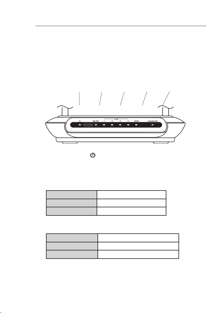
The Router has been de signed to be placed on a desktop. All of the
cables exi t from the rear of t he Router for better organizati on an d
utility. The LED indicat ors a re easil y vis ible on the fro nt of t he Ro uter
to provide you with informat ion about network ac tivity and status.
(1) (2) (3) (4) (5)
2.4GHz • High-Speed Wireless G
1. Power/Ready LED
When you apply power t o the Rout er or rest art i t, a sh ort p eriod
of time elapses whil e the R outer boots up. During th is ti me,
the Power/ Rea dy LED blinks. When the Rou ter h as co mpletely
booted up, the Power /Ready LED becomes a SOLI D lig ht,
indicati ng th e Router is rea dy for use.
OFF Router is OFF
Blinking G reen Router is Booti ng Up
Solid Green Router is Ready
2. WLAN: Wireless Network LED
OFF Wireless Network i s OFF
Gre en Wireless Network i s Rea dy
Blinking Indicates Wireless Act ivi ty
3. LAN Port-Status LEDs
These LEDs are labeled 1–4 and corresp ond t o the n umbere d
ports on the rear of t he Router. When a comput er is p roperl y
connecte d to on e of th e LAN port s on th e rear of the Router, th e
10
Page 13
Knowing Your Router
LED will light. GREE N means a 10 Base-T device is con nected,
AMBER mean s a 100Bas e-T device is connec ted. When
informat ion i s being sent over the port, the LED bli nks r apidly.
OFF No Device is Linked to the Port
Gre en 10Base-T D evi ce Connected
Orange 100B ase-Tx Device Conn ected
Blinking
(Orange or Green)
4. WAN Status LED
This LED lights in GRE EN to indi cate that your modem is
connecte d proper ly to t he Ro uter. It blinks rapidl y when
informat ion i s being sent over the port betwe en th e Router and
the modem.
OFF No WAN Lin k
Solid Green Good WAN L ink
Blinking G reen WAN Activ ity
5. Connected LED
This uniqu e LED show s you w hen t he Router is connect ed to t he
Inter net. When the light is OFF, the Router is NOT connect ed to
the Internet. When the light is blink ing, the Router is attemp ting
to connect to the Inte rnet. When the light i s sol id GR EEN, the
Router is conne cted to the Inter net. When using the “Disconn ect
after x minutes ” fea ture, th is LED becomes extremely use ful i n
monitori ng th e status of your Router’s connecti on.
Port Activ ity
1
2
secti on
3
4
5
6
7
8
9
10
11
12
OFF Router is not Connec ted to the I ntern et
Blinking G reen Router is Attem pting to Connect to the
Inter net
Solid Green Router is Conne cted to the Inter net
11
Page 14
Knowing Your Router
Knowing Your Router
13
secti on
2
1
3
4
5
6
7
8
9
10
11
12
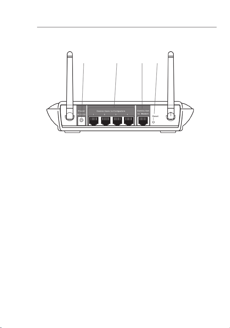
(6) (7) (8) (9)
6. Power Jack - GRAY
Connect th e inc luded 5V DC power supply to this jack .
7. Connections to Computers (LAN Ports) - BLUE
Connect yo ur wi red (non -wirel ess) computer s to th ese p orts.
These port s are RJ45, 10/100 a uto-negotia tion, auto-up linking
ports for stand ard UTP categ ory 5 o r 6 Eth ernet cabl e. Th e por ts
are l abeled 1 thro ugh 4. These ports correspon d to th e num bered
LEDs on the front of t he Router.
8. Connection to Modem (WAN Port) - GREEN
This port is for conne ction to y our cable or DSL modem. Use the
cable that was provided with t he mo dem t o connect the modem
to this port. Use of a cable other than t he ca ble s upplied with the
cable mode m may not wo rk prope rly.
9. Reset Button
The Reset butto n is us ed in rare cases whe n the R out er may
function i mprope rly. Rese tting the Router will restore the Router’s
normal ope rat ion while maint ain ing the programmed sett ings. You
can also restore t he factory default s ettings by using the Rese t
button. Us e the restore option in inst ances where y ou ma y have
forgotten your custom pass word.
12
Page 15

Knowing Your Router
a. Resetting the Router
Push and release the Reset but ton. The l ights on the Router
will momen tar ily flash. The Power /Ready light will begin t o
blink. Whe n the Powe r/Ready light beco mes solid again, the
res et is c omplete.
b. Restoring the Factory Defaults
Pre ss and hold the Reset butto n for at lea st te n sec onds
then release it. The lights on the Route r will momentarily
flash. The Powe r/Ready light will begi n to bl ink. When the
Power/Re ady l ight becomes so lid a gain, the res tore
is complet e.
1
2
secti on
3
4
5
6
7
8
9
10
11
12
13
Page 16

Connecting and Configuring Your Router
Connecting and Configuring Your Router
15
secti on
2
1
3
4
5
6
7
8
9
10
11
12
Verify the contents of your box. You should have the following:
• Belkin Hig h-S peed Mode Wireless G Router
• Quick Inst all ation Guide
• Belkin Eas y Ins tall Wizard S oftware CD
• RJ45 Ether net Networ kin g Cable (for connect ion o f the
Router to the comput er)
• Power Supp ly
• User Manua l
Modem Requirements
Your ca ble or DSL m odem must be equippe d wit h an RJ 45 Et herne t
port. Many mode ms ha ve both an R J45 Ethern et port and a USB
connecti on. I f you h ave a m odem with both Ether net and USB, and
are u sing the USB connection a t thi s tim e, you will be instructed t o
use the RJ45 Ethernet port durin g the inst allation procedu re. If your
modem has only a USB port, you can request a different type of
modem from your ISP, or you can, in some cases , purcha se a mo dem
that has an RJ45 Ether net port on it.
Ethernet USB
ALWAYS INSTALL YOUR ROUTER FIRST! IF YOU ARE INSTALLING
NUMEROUS NETWORK DEVICES FOR THE FIRST TIME, IT IS
IMPORTANT THAT YOUR ROUTER IS CONNECTED AND RUNNING
BEFORE ATTEMPTING TO INSTALL OTHER NETWORK COMPONENTS
SUCH AS NOTEBOOK CARDS AND DESKTOP CARDS.
Easy Install Wizard
Belkin has provide d our Easy I nstall Wizard software to make
installi ng yo ur Router a simple and easy task . You can use it to get
your Route r up and run ning in mi nutes.
The Easy Instal l Wiz ard requires that your Win dows® 98SE, Me,
2000, XP or Mac OS 9.2x, X.1.x com puter be c onnected directl y to
your cable or DSL mode m and that t he In terne t con nection is active
14
Page 17

Connecting and Configuring Your Router
and workin g at the tim e of insta llation. If it is not, you must use the
“Alternate Setup Met hod ” section of this manual to conf igure yo ur
Router. Addi tionally, if y ou are usi ng an oper ating system other t han
Windows 98 SE, M e, 20 00, or XP, you m ust set up the Router using
the “Alter nate Setup Meth od” s ection of this manua l.
IMPORTANT: R un th e Easy Install Wizard softwa re from the
computer t hat i s direct ly co nnected to the cable or DSL mode m.
DO NOT CONNECT THE ROUTER AT THIS TIME.
Step 1 Run the Easy Install Wizard Software
1. Shut do wn an y progra ms th at are run ning on your computer at
this time.
2. Make sure you have the following i tem s at th e com puter that is
now directly conne cte d to th e cable or D SL modem. DO NOT
CONNECT TH E ROU TER AT TH IS TI ME.
• Quick Install ation Guide
• The E asy Install Wiz ard CD-R OM
• The R outer
• The R outer power sup ply
• RJ45 Ether net n etworkin g cab le
• This User Manual
3. Turn off an y firewa ll or I nte rnet co nne ction sharing s oft ware on
your compu ter.
4. Inser t the E asy I nstall Wizard software CD into your CD–RO M
drive. The Easy Inst allation Wiza rd screen will automa tically
appear on your screen within 1 5 sec onds. If it does not, select
your CD-RO M dri ve from “My Com puter” and double- click on t he
file named “Eas yInstall.ex e” on t he CD -ROM.
1
2
3
secti on
4
5
6
7
8
9
10
11
12
15
Page 18
Connecting and Configuring Your Router
Connecting and Configuring Your Router
17
secti on
2
1
3
4
5
6
7
8
9
10
11
12
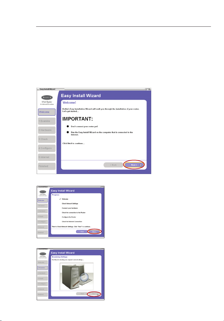
Welcome Screen
After you inser t the C D int o you r CD-ROM drive, the Wizard’s
welcome sc reen wil l app ear. Make sure you h ave n ot connected
the Router at this poi nt. I f you h ave c onnected your Rout er, please
rec onnect your com put er direc tly to the modem. Click “Ne xt” w hen
you are ready to mov e on.
Progress Screen
Easy Insta ll wi ll sh ow you a progress
screen each time a step in the setup
has been comple ted. Each time you see
the progres s screen , click “Next” when
you are ready to mov e to the nex t ste p.
Examining Settings
The Wizard will now examine yo ur
computer ’s networ k set tings and gather
informat ion n eeded to comple te th e
Router’s connecti on to t he In terne t.
When the Wizard is finished ex amining
your compu ter, cl ick “Next” to contin ue.
16
Page 19
Connecting and Configuring Your Router
Multi-NICs Screen
If you have more than one network adapte r installed in your compu ter
a Multi-NI C Screen will appe ar. If you have more tha n one n etwork
adapter insta lled in yo ur computer, the Wizard will need to know which
adapter is conn ected to your modem. Sele ct th e net work card that is
connecte d to yo ur mo dem from t he li st an d click “Next”. If you are not
sure which adapter to choose , select the adapter at the top of the list.
If you mistaken ly ch oose the wrong adapter now, you will be able to
choose a different one later.
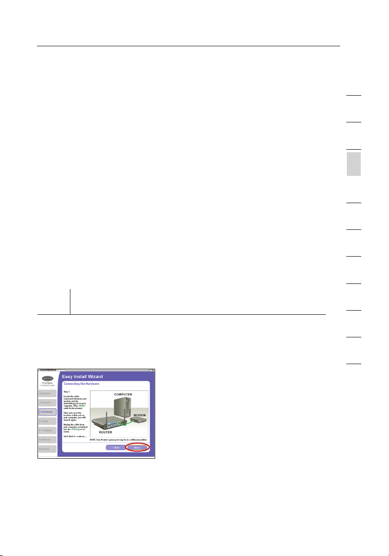
Step 2 Hardware Setup
The Wizard will walk you through conne cting your Router to your
computer a nd mo dem. Follow the steps on the screen using the
pictures as a guide.
2.1 T his s tep instructs you to loca te
the cable conne cted between your
modem and the networ king port on
your compu ter. Un plug this cable
fro m the c omputer and plug it into
the GREEN port on the Route r.
Click “Nex t” to cont inue.
1
2
3
secti on
4
5
6
7
8
9
10
11
12
17
Page 20
Connecting and Configuring Your Router
Connecting and Configuring Your Router
19
secti on
2
1
3
4
5
6
7
8
9
10
11
12
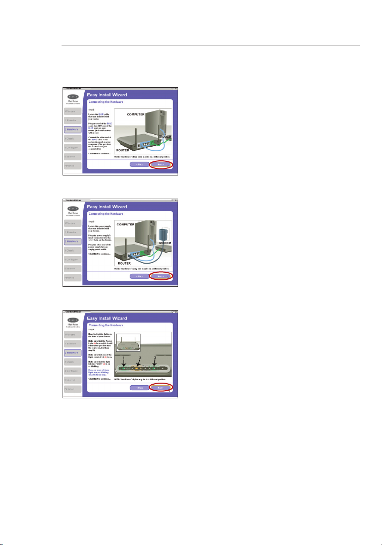
2.2 T his s tep instructs you to loca te
the BLUE cable that is incl uded
with your Route r. P lug o ne en d
of this cable into ANY one of the
BLUE ports on your Rou ter. Plug
the other end of the cable into th e
networki ng po rt on y our computer.
Click “Nex t” to cont inue.
2.3 T his s tep instructs you to loca te
the power suppl y tha t is in cluded
with your Route r. P lug t he po wer
supply’s small connect or in to the
GRAY port o n the R out er. Plug the
power supp ly in to an e mpty power
outlet. Cl ick “ Next” to continue.
2.4 T his s tep instructs you to look
at the lights on the front of your
Router. Make s ure the appropri ate
lights are ON. Refer to the Easy
Install so ftw are o n you r com puter’s
screen for more de tails. Click
“Next” to conti nue.
18
Page 21
Connecting and Configuring Your Router
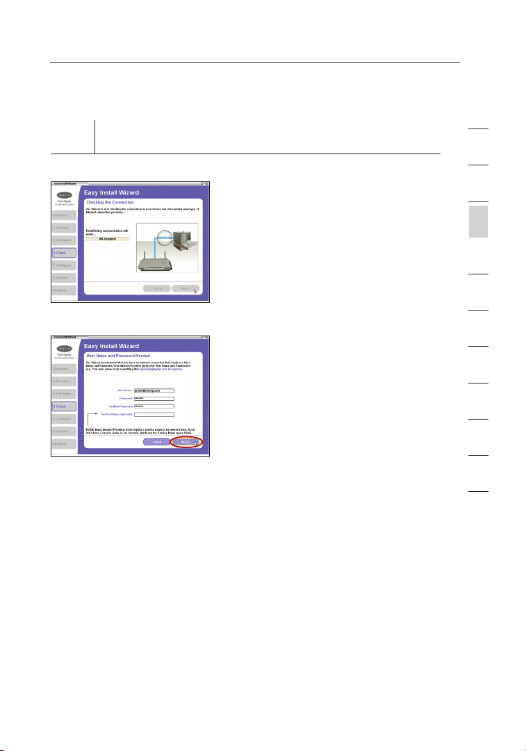
Step 3 Checking the Connection
1
2
3.1 O nce y ou have completed
connecti ng th e Router, the Wizard
will check the conne ction to the
Router and then go on to determi ne
what type of Internet connecti on
you have.
3.2 User Name and Password Needed
If you have a connection type that
requires a user name and a password,
the Wizard will ask you to type in
your user name and password. If your
connection type does not require a
user name and password, you will not
see this screen.
Your user name and password is
provided to you by your Internet
Service Provider. If you have to type
in a user name and password to
connect to the Internet, then type that
same user name and password in
here. Your user name looks something
like “jsmith@myisp.com” or simply
“jsmith”. The service name is optional
and is very rarely required by your ISP.
If you don’t know your service name,
leave this blank. When you have
entered your information, click “Next”
to move on.
3
secti on
4
5
6
7
8
9
10
11
12
19
Page 22
Connecting and Configuring Your Router
Connecting and Configuring Your Router
21
secti on
2
1
3
4
5
6
7
8
9
10
11
12
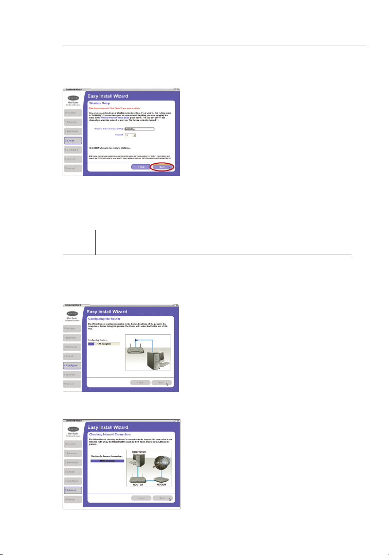
3.3 Wireless Setup
This Step Is Optional. Click “Next ” if
you want to skip it.
Using this step , you c an cu stomize
your wireless netw ork s ettings if
you want to. Follow th e ste ps on
the screen to complete this st ep.
Click “Nex t” to cont inue.
Step 4 Configuring the Router
The Wiza rd will now tr ansfer all of the c onfiguratio n informati on to th e
Router. This will take approxima tely one mi nute. Du rin g this t ime, do
not turn off the Ro uter or computer. The Router will restart i tself at th e
end of t his step.
4.1 Checking Internet
The Wizard will now check for an
Inter net connectio n. Th is can take
a few m inutes. The Wiz ard may not
detect a connec tion right away. If
not, it will retry a n umber of times.
The “Conne cte d” light on the front
panel of the Router wi ll fl ash d uring
this time. Plea se be p atient through
this process.
20
Page 23
Connecting and Configuring Your Router
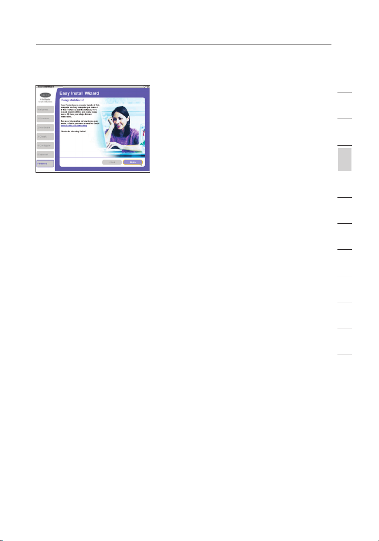
4.2 Finished
When the Internet connect ion
is complet e, th e Wiz ard will t ell
you that you are finished. The
“Connect ed” L ED on t he front o f
the Router will be sol id GR EEN,
indicati ng th at the Router is now
connecte d to th e Int ernet .
Your Router i s now co nnected to the Internet. No w you can b egin
surfing the Internet by ope ning you r b row ser and goi ng to your favorite
web page .
Congratulations! You have fin ish ed insta lling your new Belkin Router.
You are rea dy to se t up the ot her compute rs in yo ur home. You can
also add computers to your Router any time you wa nt.
1
2
3
secti on
4
5
6
7
8
9
10
11
12
21
Page 24

Alternate Setup Method
Alternate Setup Method
23
secti on
2
1
3
4
5
6
7
8
9
10
11
12
The Advanc ed Us er In terface is a web-bas ed to ol th at you can u se to
set up the Router if you don’t want to use the Easy Install W izard. You
can also use it to manage advanc ed functions of the Route r. F rom the
Advanced U ser I nterface, you can perfo rm the following tas ks:
• Vie w the R outer’s c urrent s ettings and status .
• Configure the Rout er to conn ect to your ISP with the setting s tha t
they provided you.
• Change the current netw ork s ettings such as the Inter nal IP
address, the IP address pool, DHCP set tings and more.
• Set the Router’s firewall to work with speci fic a pplications ( port
forwarding) .
• Set up security feat ure s suc h as cl ient res trictions, MA C add res s
filterin g, WE P and W PA.
• Enable the DMZ featu re for a single comp uter on your network .
• Change the Rout er’s inte rnal passw ord.
• Enable/D isable UPnP (Unive rsal Plug-and -Play).
• Reset the Route r.
• Back up your configu ration settin gs.
• Reset the Route r’s defau lt se ttings.
• Update the Rout er’s firm ware.
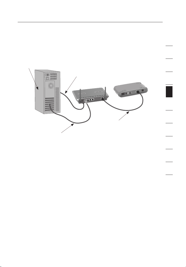
Step 1 Connecting your Router
1.1 Turn off the p ower to your modem by unpluggi ng th e power
supply from the modem.
1.2 Loca te th e network cable that is con nec ted between you r mod em
and your comput er an d unplug it fro m you r computer, leavi ng th e
other end conne cted to your modem.
1.3 Plug th e loo se en d of th e cab le you just unplugge d int o the p ort
on the back of the Router labele d “Interne t/WAN” .
1.4 C onnect a new network cabl e (no t inc luded) from the back of
the comput er to one of the ports l abeled “1–4”. Note: It does not
matter whi ch nu mbered p ort y ou choose.
22
Page 25
Alternate Setup Method
1.5 Tur n your cable or DSL mode m on by reconne cting the power
supply to the modem.
Mac or PC computer that was originally
connected to the cable or DSL modem
To Power Adapter
Existing networking cable
Note: Your Rout er ma y hav e ports in d iff ere nt lo cations than
1.6 B efore pl ugging the power cord into the Router, plu g the c ord
1.7 Ve rif y that your modem is connec ted t o the R outer by c hecking
1.8 Verify that y our c omputer is connect ed prope rly t o the R outer
Network cable
(to computer)
depicted i n the illu stration abov e.
into the wall, then pl ug th e cord into the Rout er’s powe r jac k.
the lights on the front of the Router. The green light labe led
“WA N” sh ould be ON i f your modem is connected c orrect ly to t he
Router. If it is not, recheck your conn ections.
by checkin g the ligh ts labeled “LAN 1,2, 3,4”. The light which
corresponds to the numb ere d por t con nected to your compu ter
should be ON, if your compu ter i s connected properly. If it i s not ,
rec heck your conne cti ons.
(came with modem)
1
2
3
4
secti on
5
6
7
8
9
10
11
12
23
Page 26
Alternate Setup Method
Alternate Setup Method
25
secti on
2
1
3
4
5
6
7
8
9
10
11
12
Step 2 Set your Computer’s Network Settings to Work
with a DHCP Server
See the section in thi s man ual c alled “Manual ly Co nfigurin g Net work
Settings ” for d ire cti ons.
Step 3 Configuring the Router Using the Web-Based
Advanced User Interface
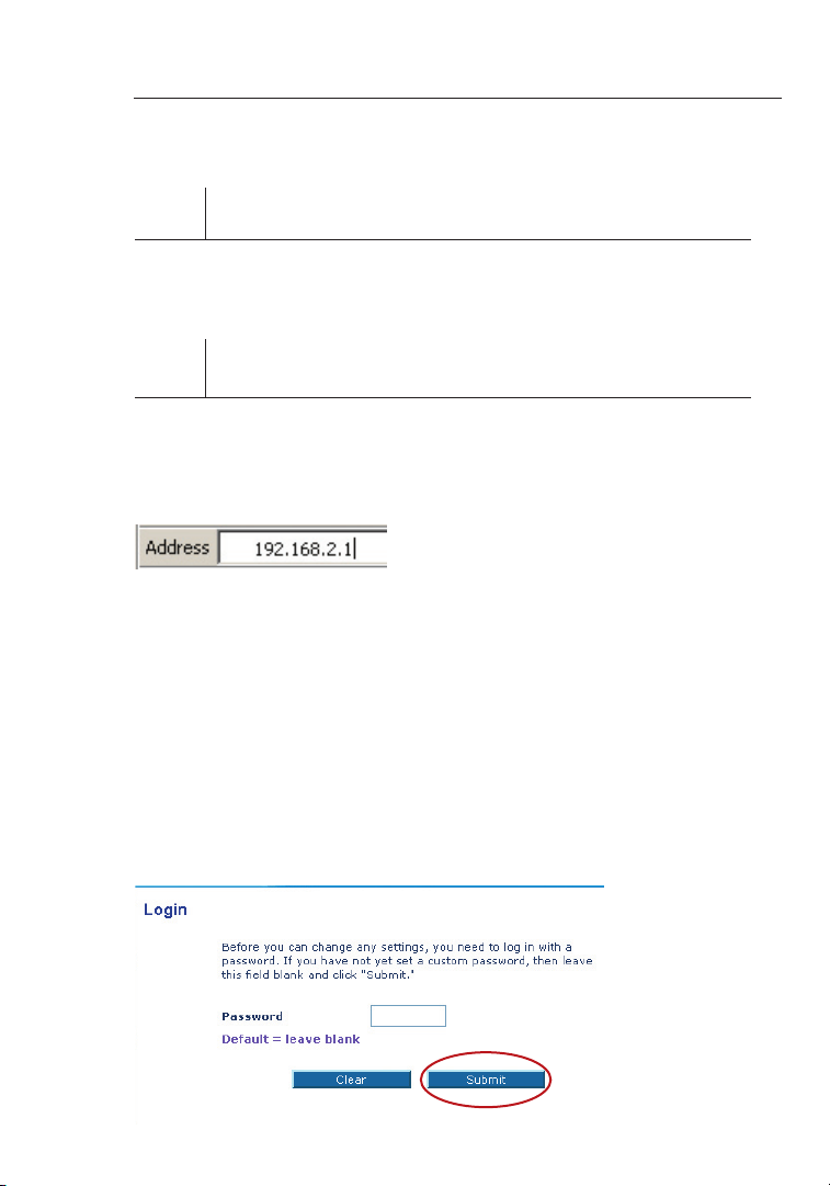
Using your Inte rnet browser, you can acces s the R outer’s Web-B ased
Advanced U ser I nterface. In your browser, typ e “19 2.168.2. 1” (y ou do
not need to type in anythin g els e such as “h ttp://” or “www ”). T hen
pre ss the “Enter” key.
PLEASE NOTE: If you have difficu lty a ccessing the Route r’s web-
based inte rfa ce, go to Section 7 of the user manual title d “Ma nually
Configur ing C omputer Netwo rk Se ttings”.
Logging into the Router
You wil l see t he Ro uter’s ho me pa ge in y our b row ser window. The
home page is visible t o any user w ho wa nts t o see i t. To make any
changes to the Route r’s setti ngs, you h ave to log in. Clicking the
“Login” bu tto n or cl icking on any one of the links on the home page
will take you to the login screen. The Rou ter s hips with no password
entered. In the login screen, leave th e pas sword bl ank a nd click the
“Submit” b utt on to l og in.
24
Page 27
Alternate Setup Method
Logging out of the Router
One comput er at a time can log in to the Route r for t he pu rposes
of making chang es to t he se ttings of the Router. Once a user ha s
logged in to make chan ges, there are two ways that the co mpu ter
can be logged out. Cli cking the “Logout” butt on wi ll log the c omputer
out. The second meth od is a utomatic. The logi n wil l time out a fter a
specifie d per iod of time. The default lo gin t ime o ut is 1 0 min utes. This
can be changed from 1 to 99 m inutes. For more informati on, s ee the
section in this manu al titled “Changin g the L ogin Timeout Setti ng”.
Understanding the Web-Based Advanced User Interface
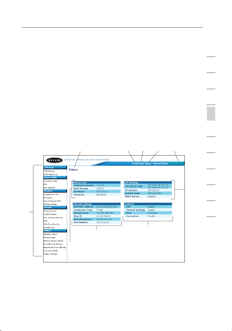
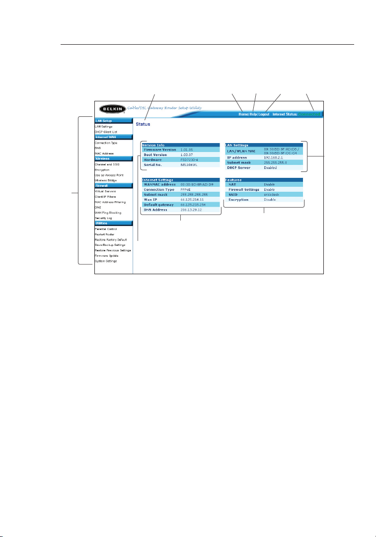
The home page is the first page yo u wil l see w hen y ou ac cess the
Advanced U ser I nterface (UI) . The home p age s hows you a q uick view
of the Router’s status and setting s. Al l advanced setu p pag es ca n be
rea ched fro m this page.
(10) (2) (5) (4) (3)
(6)
(1)
(7)
(8)
(9)
1
2
3
4
secti on
5
6
7
8
9
10
11
12
1. Quick-Navigation Links
You can g o direct ly to a ny of the Ro uter’s advan ced UI pages by
clicking d irectl y on th ese l inks. The links are divided into lo gic al
categori es an d gro upe d by ta bs to m ake f inding a particula r
setting ea sie r to fi nd. Clicking on the purpl e hea der of each tab
will show you a short descr iption of the tab’s f unction.
25
Page 28
Alternate Setup Method
Alternate Setup Method
27
secti on
2
1
3
4
5
6
7
8
9
10
11
12
(10) (2) (5) (4) (3)
(1)
(7)
(8)
(9)
2. Home Button
The home button is ava ilable in every page of the UI. Pressing
this butto n wil l tak e you b ack t o the h ome p age.
3. Internet Status Indicator
This indic ato r is vi sible in all pages of the Router, in dicating
the connec tio n status of the Router. When th e ind icator says
“connect ion O K” in G REEN, the Router is conne cted to the
Inter net. When the Router is not conn ected to the Internet, the
indicato r wil l rea d “no conn ection” in RED. The indic ator is
automati cally updated when y ou ma ke ch anges to the setting s of
the Router.
4. Login/Logout Button
This butto n ena bles you to log i n and o ut of t he Ro uter with the
pre ss of o ne button. When you are logged into the Route r, t his
button wil l cha nge t o read “Lo gout”. Logging int o the Rout er will
take you to a separate logi n pag e where yo u wil l nee d to en ter a
password. When you are logged in to the Router, you ca n mak e
changes to the setti ngs. When you are fi nished making chan ges,
you can log out of the Router by clicki ng th e “Logout” butt on. F or
more information a bou t logging into the Router, se e the s ection
called “Lo ggi ng into the Router”.
(6)
26
Page 29

Alternate Setup Method
5. Help Button
The “Help” butt on gi ves you access to the Router’s help pages.
Help is also availab le on m any p ages by clicking “mo re info” next
to certain sect ions of each page.
6. LAN Settings
Shows you the settin gs of t he Lo cal Area N etwork (LAN) side of
the Router. Ch ang es can be ma de to t he settings by click ing o n
any one of the links (IP Address, Subnet M ask, DHCP Server) or
by clickin g the “LAN ” Quick Navigation l ink o n the l eft s ide o f
the screen.
7. Features
Shows the statu s of th e Rou ter’s NAT, firewall, and wireless
features. Change s can b e mad e to th e set tings by clicking on any
one of the links or by clicking th e “Qu ick N avigatio n” li nks o n the
left side of the screen.
8. Internet Settings
Shows the setti ngs o f the I ntern et/WAN side o f the Rout er that
connects t o the Inte rnet. Chan ges to any o f these settings can
be made by clicking on the links o r by cl ick ing on the “ Inter net/
WAN ” Qui ck Navigation l ink o n the l eft s ide o f the s cre en.
9. Version Info
Shows the firmw are vers ion, boot-cod e ver sion, hardware
version, a nd se rial number of the Router.
10. Page Name
The page you are on ca n be id entified by this nam e. Th is ma nual
will somet ime s ref er to page s by na me. F or instance “LAN > LAN
Settings ” refers t o the “LAN S ettings” page.
1
2
3
4
secti on
5
6
7
8
9
10
11
12
27
Page 30
Alternate Setup Method
Alternate Setup Method
29
secti on
2
1
3
4
5
6
7
8
9
10
11
12
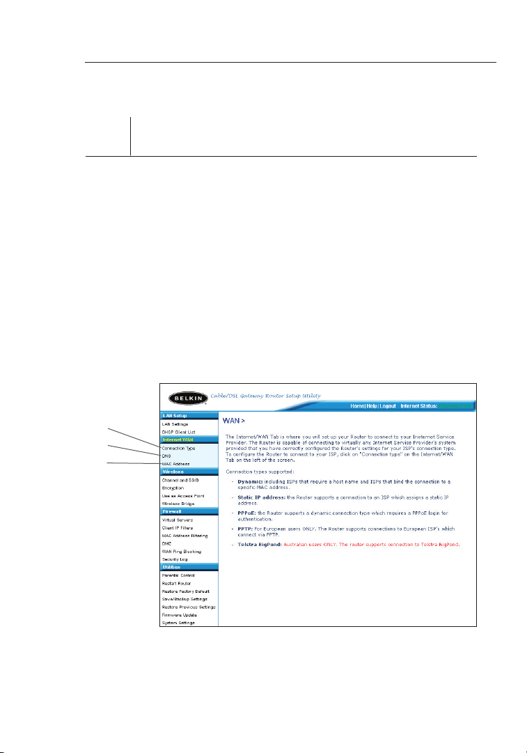
Step 4 Configuring your Router for Connection to your Internet
Service Provider (ISP)
The “Inter net/WAN” tab is where y ou wi ll set up your Router to
connect to your Inte rnet Servi ce Provi der (ISP). The Route r is capab le
of connect ing t o vir tually any ISP’s sy stem provided you have
correctly config ure d the R out er’s sett ings for your ISP’s c onnection
type. Your ISP connection s ettings are p rov ided to you by yo ur ISP.
To conf igure th e Router with the setting s tha t your ISP gave you,
click “Con nec tion Type” (A) on th e left side of the screen. Select
the connec tio n type you use. If your ISP gave you DNS setti ngs ,
clicking “ DNS ” (B) allows you to enter DNS address entri es fo r ISPs
that require specific sett ing s. Clicking “MA C add res s” (C) w ill l et yo u
clone your comp uter’s MA C add res s or type in a specifi c WAN MAC
address, if require d by yo ur ISP. When you have fi nis hed making
settings , the “ Inter net S tatus” indica tor w ill read “con nection OK” if
your Route r is set up properly.
(A)
(B)
(C)
28
Page 31

Alternate Setup Method
Setting your Connection Type
From the connection type page, you can select the type of connection you
use. Select the type of connection you use by clicking the button (1) next
to your connection type and then clicking “Next” (2).
(1)
(2)
1
2
3
4
secti on
5
6
7
8
9
10
11
12
29
Page 32

Alternate Setup Method
Alternate Setup Method
31
secti on
2
1
3
4
5
6
7
8
9
10
11
12
Setting your Internet Service Provider (ISP) Connection Type
to Dynamic IP
A dynamic conne ction type is the most common conne ction type
found with cabl e mod ems. Setting the con nection type to “dynami c”
in many cases is enoug h to compl ete the connection t o you r ISP.
Some dynam ic co nnection type s may require a host name. You can
enter your host name i n the spac e provid ed if y ou we re as sig ned one.
Your ho st name is a ssigned by your ISP. Som e dyn amic connecti ons
may require t hat y ou clone the MAC address of the PC that was
original ly co nnected to the modem .
(1)
(2)
(3)
1. Host Name
This space is provided to ente r a host nam e tha t nee ds to b e
visible to your ISP. Ent er your host name here and click “Apply
Changes” (3). If y our I SP di d not a ssign you a host name, or you
are n ot su re, leav e this blank.
2. Change WAN MAC Address
If your ISP requires a sp ecific MAC address to connec t to the
service, y ou ca n ent er a sp ecific MAC address or clone the
current computer ’s MAC address through this link .
30
Page 33

Alternate Setup Method
Setting your Internet Service Provider (ISP) Connection Type
to Static IP
A static IP address connection type is less common than other connection
types. If your ISP uses static IP addressing, you will need your IP address,
subnet mask, and ISP gateway address. This information is available from
your ISP or on the paperwork that your ISP left with you. Type in your
information, then click “Apply Changes” (5). After you apply the changes,
the Internet Status indicator will read “connection OK” if your Router is set
up properly.
(1)
(2)
(3)
(4)
(5)
1
2
3
4
secti on
5
6
7
8
9
10
11
12
1. IP Address
Pro vided by your ISP. Ente r you r IP ad dre ss he re.
2. Subnet Mask
Pro vided by your ISP. Ente r you r sub net mask here.
3. ISP Gateway Address
Pro vided by your ISP. Ente r the I SP ga teway address here.
4. My ISP Provides More Than One Static IP Address
If your ISP assigns yo u more than one stat ic IP a ddress , you r
Router is capab le of h andling up to five static WAN IP ad dre sses.
Select “My ISP provides more than one stati c IP ad dre ss” a nd
enter your addi tional addresses.
31
Page 34

Alternate Setup Method
Alternate Setup Method
33
secti on
2
1
3
4
5
6
7
8
9
10
11
12
Setting your ISP connection type to PPPoE
Most DSL providers use PPPoE a s the conn ection type. If you use a
DSL modem to connect t o the Inte rnet, your I SP ma y use P PPoE to
log you into the servi ce. I f you h ave a n Int ernet c onn ection in your
home or small office that does n’t require a mo dem, you may also use
PPPoE.
(1)
(2)
(3)
(4)
(5)
Your connection type is PPPoE if:
1) Your I SP ga ve you a user name and password which is required to
connect to the Inter net
2) Your I SP ga ve you software such as WinPOET or Enter net30 0 tha t
you use to connect to the Internet
3) You ha ve to d ouble-click o n a deskto p Icon other than your
bro wser to get on the Inter net
(6)
32
Page 35

Alternate Setup Method
1. User Name
This space is provided to type in your Use r nam e tha t was
assigned b y you r ISP.
2. Password
Type in y our p assword and re-t ype i t into the “Retype Passwo rd”
box to confirm it.
3. Service Name
A Service name is rarely required by a n ISP. If you are n ot su re if
your ISP requires a service name, leav e thi s bla nk.
4. MTU
The MTU setting shou ld never be changed unles s you r ISP g ives
you a s pecific MTU set ting. Making chang es to the MT U set ting
can cause problems with your I nternet co nnection includi ng
disconne ction from th e Inter net , slow Inter net a ccess and
pro blems with Inte rnet appli cat ions working properly.
5. Disconnect after X...
The Discon nec t feature is us ed to a utomaticall y disconnect the
rou ter from y our I SP when there i s no ac tivity for a specified
period of time. For in stance, placing a check mark next to this
option and ente ring 5 into the m inute field will cau se th e router
to disconn ect f rom the Inter net after 5 minut es of n o Int ernet
activity. This option sh oul d be us ed if y ou pa y for y our I ntern et
service by the minut e.
1
2
3
4
secti on
5
6
7
8
9
10
11
12
33
Page 36

Alternate Setup Method
Alternate Setup Method
35
secti on
2
1
3
4
5
6
7
8
9
10
11
12
Setting your Internet Service Provider (ISP) Connection Type to
Point-to-Point Tunneling Protocol (PPTP)
[European Countr ies O nly]. Some ISPs require a connection usin g
PPTP protocol, a type of conne ction most common in European
countrie s. Th is sets up a d ire ct co nnection to the ISP’s system. Type
in the informat ion p rov ided by your ISP in the space provided. When
you have finish ed, c lick “Apply Change s” (9). Afte r you a pply the
changes, t he In terne t Sta tus i ndicator will read “connec tion OK” if
your Route r is set up properly.
(1)
(2)
(3)
(4)
(5)
(6)
(7)
(8)
(9)
1. PPTP Account
Pro vided by your ISP. Ente r you r PPT P account name here.
2. PPTP Password
Type in y our p assword and rety pe it i nto t he “Retype Password”
box to confirm it.
3. Host Name
Pro vided by your ISP. Ente r you r hos t name here.
34
Page 37

Alternate Setup Method
4. Service IP Address
Pro vided by your ISP. Ente r you r ser vice IP address here.
5. My IP Address
Pro vided by your ISP. Ente r the I P add res s here.
6. My Subnet Mask
Pro vided by your ISP. Ente r the I P add res s here.
7. Connection ID (optional)
Pro vided by your ISP. If your ISP did not giv e you a conn ection
ID, leave this blank .
8. Disconnect after X….
The Discon nec t feature is us ed to a utomaticall y disconnect the
Router from your ISP when there is no activity for a spec ifi ed
period of time. For in stance, placing a check mark n ext t o thi s
option and ente ring “5” into the minute field will c ause the R outer
to disconn ect f rom the Inter net after fi ve mi nutes of no Inter net
activity. This option sh oul d be us ed if y ou pa y for y our I ntern et
service by the minut e.
1
2
3
4
secti on
5
6
7
8
9
10
11
12
35
Page 38

Alternate Setup Method
Alternate Setup Method
37
secti on
2
1
3
4
5
6
7
8
9
10
11
12
Setting your Connection Type if you are a Telstra® BigPond User
[Austral ia On ly] Yo ur user name and password are pro vided to y ou by
Telstra BigPond . Ent er th is informatio n bel ow. Ch oosing your sta te
fro m the d rop -down menu (6) will automa tically fill in your logi n ser ver
IP address. If your login serv er ad dre ss is different than on e provid ed
here, you may manually enter t he lo gin s erver IP address by placing a
check in the box next to “User dec ide l ogin server manual ly” (4) and
type in the address next to “Login Serve r” (5). When you have entered
all of your informat ion, click “Apply Ch anges” (7). After you appl y the
changes, t he In terne t Sta tus i ndicator will read “connec tion OK” if
your Route r is set up properly.
(1)
(2)
(3)
(4)
(5)
(7)
(6)
1. Select your State
Select you r sta te from the drop-down m enu (6). The “Login
Server” bo x wil l aut omatical ly be fill ed in w ith a n IP ad dre ss.
If for some reason this address does not match the address
that Telstra has given, you can ma nua lly enter the login serve r
address. See “User Deci de Lo gin Server Manuall y” (4).
2. User Name
Pro vided by your ISP. Type in your user name here.
36
Page 39

Alternate Setup Method
3. Password
Type in y our p assword and rety pe it i nto t he “Retype Password”
box to confirm it.
4. User Decide Login Server Manually
If your login server I P add res s is not ava ilable in the “Select Your
State” drop-down m enu (6), yo u may m anually enter the lo gin
server IP address by placing a chec k in th e box n ext t o “Us er
decide log in se rver manually ” and type i n the address next t o
“Login Ser ver ” (5).
Setting Custom Domain Name Server (DNS) Settings
A “Domain Name Server” is a server located on the Internet that
translates Universal Resource Locater (URLs) like “www.belkin.com”
to IP addresses. Many Internet Service Providers (ISPs) do not require
you to enter this information into the Router. The “Automatic from ISP”
box (1) should be checked if your ISP did not give you a specific DNS
address. If you are using a static IP connection type, then you may
need to enter a specific DNS address and secondary DNS address for
your connection to work properly. If your connection type is dynamic
or PPPoE, it is likely that you do not have to enter a DNS address.
Leave the “Automatic from ISP” box checked. To enter the DNS address
settings, uncheck the “Automatic from ISP” box and enter your DNS
entries in the spaces provided. Click “Apply Changes” (2) to save
the settings.
(1)
1
2
3
4
secti on
5
6
7
8
9
10
11
12
37
(2)
Page 40

Alternate Setup Method
Alternate Setup Method
39
secti on
2
1
3
4
5
6
7
8
9
10
11
12
Configuring your WAN Media Access Controller
(MAC) Address
All networ k com ponents inclu din g cards, a dapters, and routers, have
a unique “seria l num ber” called a MAC address. Your I ntern et Se rvice
Pro vider may record t he MA C addres s of yo ur co mputer’s adapter and
only let that partic ular computer conn ect to the I ntern et se rvice. When
you instal l the Rout er, its o wn MAC address will be “seen” by the
ISP and may cause the conne ction not to work. Belkin has provided
the abilit y to clone ( copy) the MAC address of the c omputer into th e
Router. This M AC ad dre ss, i n tur n, will be seen by the ISP’s s ystem as
the origin al MA C add res s and w ill a llow the connectio n to wo rk. I f you
are n ot su re wheth er your ISP needs to see the original M AC ad dre ss,
simply clo ne th e MAC a ddress o f the comp uter that was origin ally
connecte d to th e mod em. Cloning the address will not cause a ny
pro blems with your netw ork.
38
Page 41

Alternate Setup Method
Cloning your MAC Address
To clon e your MAC a ddress, make sure that you are us ing t he co mputer
that was ORIGIN ALLY C ONNECTED to your modem be fore the Rout er
was instal led . Click the “Clone” butto n (1). C lick “Apply Change s” (3).
Your MA C addres s is no w clo ned to the Router.
Entering a Specific MAC Address
In certain circums tan ces you may need a specific WAN MAC address.
You can m anually enter one in the “MAC Address” page . Type in a
MAC address in the spaces provided (2) an d cli ck “A pply Changes” (3)
to save the changes. T he Ro uter’s WAN MAC address will now be
changed to the MAC add ress you spec ified.
(2)
(1)
(3)
1
2
3
4
secti on
5
6
7
8
9
10
11
12
39
Page 42

Using the Web-Based Advanced User Interface
Using the Web-Based Advanced User Interface
41
secti on
2
1
3
4
5
6
7
8
9
10
11
12
Using your Inte rnet browser, you can acces s the R outer’s Web-B ased
Advanced U ser I nterface. In your browser, typ e “19 2.168.2. 1” (d o
not type in anything e lse s uch a s “http://” or “www” ) the n press th e
“Enter” ke y.
You wil l see t he Ro uter’s ho me pa ge in y our b row ser window.
Viewing the LAN Settings
Clicking o n the head er of t he LA N tab (1) will take y ou to the LA N
tab’s hea der page. A quick descrip tion of the function s can be
found here. To vie w the s ettings or make changes t o any of the LAN
settings , cli ck on “ LAN Settings” (2) or to view the li st of conn ected
computer s, cl ick on “DHCP Client List” (3).
(1)
(2)
(3)
40
Page 43

Using the Web-Based Advanced User Interface
Changing LAN Settings
All settin gs fo r the i nternal LA N set up of t he Ro uter can be viewed
and change d here.
(1)
(2)
(3)
(4)
(5)
(6)
1. IP Address
The “IP address” is the internal IP address of the R outer. The
default IP address is “192.1 68.2.1”. To access the advance d
setup inte rfa ce, type this IP address into the address bar of your
bro wser. This address can be change d if ne eded. To cha nge t he
IP address, type in the new IP address and click “Apply C han ges”.
The IP address you choose shou ld be a non- routab le IP.
Examples o f a non-routa ble I P are:
192.168. x.x ( where x is anyt hing between 0 and 255)
10.x.x.x ( whe re x is anythin g between 0 and 255)
2. Subnet Mask
There is n o need to ch ange the subnet mask . Thi s is a uniqu e,
advanced f eat ure o f you r Bel kin Router. It is possib le to chan ge
the subnet mask if nec essary, howe ver, do NOT make chan ges to
the subnet mask unle ss you have a specific reason to do so. The
default se tti ng is “ 255.255. 255 .0”.
1
2
3
4
5
secti on
6
7
8
9
10
11
12
41
Page 44

Using the Web-Based Advanced User Interface
Using the Web-Based Advanced User Interface
43
secti on
2
1
3
4
5
6
7
8
9
10
11
12
3. DHCP Server
The DHCP server func tion makes setting u p a networ k very easy
by assigni ng IP address es to e ach c omputer on the network
automati cally. Th e def ault setting is “On” . The DHCP s erver
can be turne d OFF i f nec essary, h owever, in order to do s o you
must manua lly s et a st atic IP ad dre ss fo r each computer on
your netwo rk. To turn off the DHCP serv er, select “Off” and click
“Apply Cha nge s”.
4. IP Pool
The range of IP addresses set aside for dynamic assignment to th e
com puters on your network . The default i s 2–100 ( 99 computers) . If
you want to change this number, you ca n do so by entering a n ew
sta rting and ending IP addre ss and clicking on “A pply Changes” .
The DHCP server ca n assign 100 IP addresses autom atically. This
mea ns that you can not specify an IP add ress pool larger than 100
com puters. For example, starting at 5 0 means you hav e to end at
150 or lower so as n ot to exceed th e 100-client limit. The starting
IP address must be lower in nu mber than the e nding IP address .
5. Lease Time
The length of time the DHCP serv er will re serve the IP addre ss
for each comput er. We recommend t hat y ou le ave the lease
time set to “Forever”. The def ault setting is “Forever”, mean ing
that any time a comput er is assi gned an IP a ddress b y the
DHCP serve r, t he IP address will n ot ch ange for that particula r
computer. Se tting lease times fo r sho rter interval s suc h as on e
day or one hour frees IP addre sses after the speci fied period of
time. This also mean s that a par ticular compu ter’s IP address
may change over time . If yo u hav e set a ny of t he ot her a dvanced
features of the Router such as DMZ or clie nt IP f ilt ers, these are
dependen t on th e IP ad dress. F or th is reaso n, yo u will not w ant
the IP address to change.
6. Local Domain Name
The default setting is “Belkin”. You can set a local domain name
(network name) for your network. There is no need to change this
setting unless you have a specific advanced need to do so. You can
name the network anything you want such as “MY NETWORK”.
42
Page 45

Using the Web-Based Advanced User Interface
Viewing the DHCP Client List Page
You can v iew a l ist o f the c omputers (known as clie nts), which are
connecte d to yo ur ne twork. You are abl e to view th e IP address (1) of
the comput er, the h ost n ame (2) (if the computer has been a ssi gned
one), and the MAC address (3) of the comput er’s netw ork i nterface
card (NIC). Pressing the “Refresh” (4) but ton w ill u pdate the list. If
there have been any changes, t he li st wi ll be u pdated.
(1) (2) (3)
(4)
1
2
3
4
5
secti on
6
7
8
9
10
11
12
43
Page 46

Using the Web-Based Advanced User Interface
Using the Web-Based Advanced User Interface
45
secti on
2
1
3
4
5
6
7
8
9
10
11
12
Configuring the Wireless Network Settings
The Wireless tab lets you make chan ges t o the w ire less network
settings . From thi s tab you ca n mak e cha nges to the wireless network
name (SSID ), op erating chann el, e ncryption sec uri ty settings, an d
configure the Rout er to be use d as an acce ss po int.
Changing the Wireless Network Name (SSID)
To iden tify your wireless netw ork , a nam e cal led the SSID (Servic e
Set Identi fie r) is u sed. The default SSI D of the Rou ter i s “be lkin54g” .
You can c hange this to anything yo u wan t to or you can lea ve it
unchange d. If t here are other wireless netwo rks operating in you r
are a, you will want to make sure that your SSID is unique (doe s not
match that of anothe r wirele ss network in the area). To chan ge the
SSID, type in the SSID that you wa nt to u se in the SS ID fi eld (1) and
click “App ly Ch anges” (2). The chang e is im med iate. If you make a
change to the SSID, yo ur wi rel ess-equippe d com puters may also need
to be reco nfigured to connect to your new networ k name. Refer to the
document ation of your wireless netwo rk ad apter for informat ion o n
making thi s cha nge.
(1)
44
(2)
Page 47

Using the Web-Based Advanced User Interface
Using the Wireless Mode Switch
Your Ro uter can operate in three different wireless modes: “802. 11gAuto”, “80 2.1 1g-Only” , and “ 802 .11g-LRS ”. Th e different mode s are
explaine d bel ow.
802.11g-Auto Mode
In this mode, the Rout er is comp atible with 802.11 b and 8 02.11g
wireless clients s imu ltaneous ly. This is the facto ry de fault mode and
ensures successf ul op eration with al l Wi- Fi-compatib le devices. If
you have a mix of 802.11b and 802. 11g c lients in your netwo rk, w e
rec ommend settin g the R outer to 802.11g-A uto m ode. This setting
should onl y be chang ed if y ou ha ve a sp ecific reason to do so.
802.11g-Only Mode
802.11g- Only mode works with 802. 11g c lients only. T his mode
is re commended onl y if you wan t to prevent 802.1 1b clients from
accessin g you r network. To switch modes, sele ct th e des ire d
mode from the “Wireless Mode” drop-down box. T hen, click
“Apply Cha nge s”.
802.11g-LRS Mode
We recomm end you DO N OT use this mode unless you have a very
specific reason to do so. This mode exis ts only to s olve unique
pro blems that may occur with s ome 8 02.11b client adap ters and is
NOT necess ary f or in teroperability o f 802 .11g and 802.11b standa rds .
When to Use 802.11g-LRS Mode
In some cases, older 8 02.11b clients may not be comp atible with
802.11g wi reless . The se adapters ten d to be of inferi or de sign and
may use older driver s or te chnology. 80 2.11g-LR S (Li mited Rate
Support) a llo ws these client s to be comp atible with the newer
802.11g te chn ology. Sw itching to this mode can solve p roblem s that
sometime s occ ur with these client s. If y ou su spect that you are u sing
a client adapte r tha t falls into this categor y of ad apters, first chec k
with the adapte r ven dor to see i f there is a driv er up date. If there
is no d river update av ailable, switchi ng to 8 02.11g-LRS mo de ma y
fix your problem. Please note that switching to 802.11g-LRS mode may
decrease 802.11g performance slightly.
1
2
3
4
5
secti on
6
7
8
9
10
11
12
45
Page 48

Using the Web-Based Advanced User Interface
Using the Web-Based Advanced User Interface
47
secti on
2
1
3
4
5
6
7
8
9
10
11
12
Using High-Speed Mode
The Router supp orts two High-Spee d mod es, 125HSM* mode and
Frame Burs tin g mode.
Selectin g “12 5HSM mode” will result in all devic es ru nning in 125HSM
mode if all devices are capabl e of 125Mb ps speeds. If any
non-125H SM de vice connects o r ass ociates with the networ k, the
Router wil l aut omatically sh ift t he en tire net work back to Frame
Bursting m ode .
Selectin g “Fr ame Bursting” w ill resu lt in all de vices capable of
Frame Burs tin g to fu nction in Frame Burs ting mode, and all clients
not capabl e, to oper ate in normal 802.11 g mod es. F rame Bursting
mode suppo rts b oth F rame Bursting -enabled devi ces a nd no n-Frame
Bursting -enabled devi ces s imultane ous ly. Frame Burs ting mode is
based on the unreleased 802. 11e specifica tion.
Selectin g “Off” wi ll di sable Turbo mode.
*When operating in High-Speed Mode, this Wi-Fi device may achieve an actual throughput
of up to or greater than 34.1Mbps, which is the equivalent throughput of a system following
802.11g protocol and operating at a signaling rate of 125Mbps. Actual throughput will vary
depending on environmental operational and other factors.
46
Page 49

Using the Web-Based Advanced User Interface
Changing the Wireless Channel
There are a number o f ope rating channe ls yo u can c hoose from. I n
the United Stat es an d Australia, there are 11 ch annels. In the Unite d
Kingdom an d mos t of Eu rope, th ere are 13 channels. In a small
number of other coun tries, there are o ther channel requirements.
Your Ro uter is configured to operat e on th e proper chan nels for
the countr y you reside in. The defa ult c hannel is 11 (unless you are
in a co untry that does not allow c hannel 11). The channel c an be
changed if need ed. I f there are other wireless netw orks operatin g in
your area, your network shou ld be s et to o perate on a channel that is
different t han the other wireless netwo rks. For best performan ce, use
a channel that is at least five ch annels away from t he other wireless
network. F or in stance, if another netw ork is operating on chann el 11 ,
then set your networ k to ch annel 6 or b elow. To chan ge th e cha nnel,
select the chan nel f rom the drop-dow n list. Click “Apply Chan ges”.
The change is immedi ate.
1
2
3
4
5
secti on
6
7
8
9
10
11
12
47
Page 50

Using the Web-Based Advanced User Interface
Using the Web-Based Advanced User Interface
49
secti on
2
1
3
4
5
6
7
8
9
10
11
12
Using the Broadcast SSID Feature
Note: This advanced feature should be employed by advanced users only.
For securi ty, you can choose not to broadcas t you r net work’s SS ID.
Doing so will keep you r net work name hidden from computers t hat
are s canning for the presence of wireless netw orks. To tur n off the
bro adcast of the SSID, remove the chec k mar k from the box next to
“Broadcast SSID” , and t hen c lick “Apply Change s”. The change is
immediat e. Ea ch computer now need s to be set to conn ect t o you r
specific S SID ; an SS ID of “ ANY” will no longer be accepte d. Re fer to
the docume nta tion of your wireless networ k ada pter for informati on
on making this chang e.
Protected Mode Switch
As part of the 802.11g spec ification, Protecte d Mode ensures pro per
operatio n of 80 2.11g clients and acces s points when there is heavy
802.11b tr affic in the opera ting environment . Whe n Protec ted m ode
is ON, 802.11g scans f or ot her w ire less network traffic before it
transmit s dat a. There fore, us ing this mode in environment s wit h
HEAVY 802.1 1b tr aff ic or i nte rference achieve s bes t performance
res ults. If you are in an envi ron ment with very littl e—o r no—other
wireless network t raffic , you r best performa nce w ill b e achieved with
Pro tected mode OFF.
48
Page 51

Using the Web-Based Advanced User Interface
Securing your Wi-Fi® Network
Here are a few different ways you can maxim ize t he se curity of
your wireless netw ork a nd prote ct yo ur data from pr ying eyes and
ears. This sect ion i s intended for the home, home office, an d sma ll
off ice user. At the time of this manual ’s public ati on, there are three
encrypti on me thods availab le.
Name 64-bit Wired
Equivalent
Privacy
Acrony m 64-bit WEP 128-bit WE P WPA- TKI P W PA-AE S
Securi ty G ood Better B est Best
Featur es Static keys Sta tic keys Dynami c key
Encryp tio n
keys based
on RC 4
algori thm
(typic all y
40-bit keys)
128-bit Wired
Equivalent
Privacy
More secure
than 64-bit
WEP u sing a
key l ength of
104 b its pl us
24 ad ditional
bits of sys tem
genera ted
data.
Wi-Fi Protected
Access-TKIP
encryp tio n
and m utual
authen tic ati on.
TKIP (temporal
key i ntegrity
pro toc ol)
added so
that keys a re
rot ate d and
encryp tio n is
streng the ned.
With Protected
Access
Dynami c key
encryp tio n
and m utual
authen tic ati on.
AES (Advance d
Encryp tio n
Standa rd) do es
not c ause a ny
throug hpu t
loss.
WEP (Wired Equivalent Privacy)
WEP (Wired Equival ent P rivacy) is a common protocol that adds
security t o all Wi-F i-compli ant w ire les s pro ducts. WEP was designed
to give wireless networ ks th e equivalent level o f pri vacy pro tection as
a comparab le wi red netw ork.
1
2
3
4
5
secti on
6
7
8
9
10
11
12
64-Bit WEP
64-bit WEP was first i ntrodu ced with 64-bit encr yption, which
includes a key lengt h of 40 bits p lus 2 4 add itional bits of
system-g enerated data (64 bi ts to tal). Some hardware m anufactu rers
ref er to 6 4-bit as 40-bit encr yption. Shortly af ter t he te chnology was
introduced, researcher s fou nd th at 64-bit encrypti on was too e asy
to decode.
49
Page 52

Using the Web-Based Advanced User Interface
Using the Web-Based Advanced User Interface
51
secti on
2
1
3
4
5
6
7
8
9
10
11
12
128-Bit WEP
As a resul t of 64 -bit WEP’s pot ential securi ty we aknesses, a more
secure method of 128-bi t enc ryption was develo ped. 128-bit
encrypti on in cludes a key length of 104 bits plus 24 addi tional bits of
system-g enerated data (128 b its t otal). Some hardware manufact urers
ref er to 1 28-bit as 104-bit en cryption.
Most of the new wireless equip ment in th e market today suppo rts
both 64-bi t and 128- bit WEP encryption , but y ou mi ght have older
equipmen t tha t only supports 64-b it WE P. All Belkin wireless products
will suppo rt bo th 64 -bit and 128-bit WEP.
Encryption Keys
After selecting either the 64-bit or 128-bit WEP encryption mode, it is
critical that you generate an encryption key. If the encryption key is
not consistent throughout the entire wireless network, your wireless
networking devices will be unable to communicate with one another
on your network and you will not be able to successfully communicate
within your network.
You can e nter your key by typing in the hex key manually, or you can
type in a passphrase i n the “Pas sphrase” fiel d and c lick “Generate”
to create a key. A hex (hexadec imal) key is a mi xture of n umbers and
letters from A–F and 0–9. For 64-bi t WEP, y ou need to e nter 10 hex
keys. For 128-b it WE P, you need to enter 26 hex keys.
For instan ce:
AF 0F 4B C3 D4 = 64-bit WEP key
C3 03 0F AF 0F 4B B2 C3 D4 4B C3 D4 E7 = 128-bit WEP key
The WEP passphr ase i s NOT t he sa me as a W EP ke y. Your c ard uses
this passp hra se to g enerate your WEP key s, bu t different hardware
manufact ure rs mi ght h ave diff ere nt methods on genera ting the k eys.
If you have multiple v endors’ equipmen ts in y our n etwork, the easies t
thing to do is to use the hex WEP key fro m you r Router or access
point and enter it man ually into the hex WEP key table in your card’s
configur ation screen.
50
Page 53

Using the Web-Based Advanced User Interface
WPA (Wi-Fi Protected Access)
WPA (Wi-F i Pro tec ted Access) is a new Wi-Fi stand ard that was
designed t o imp rov e upo n the s ecurity features of WEP. To use W PA
security, the drivers an d sof tware of your w ireles s equipment must
be upgrade d to suppo rt WPA. These up dat es will be found on the
wireless vendors w ebs ite. There are two type s of WPA securit y, WPAPSK (no server) and WPA (with radius serv er).
WPA-PSK (no server) uses what is known as a
Pre -Shared key as the Network key. A Ne twork key is basically a
password that is betwee n 8 and 63 charac ters long. It can be a
combinat ion o f letters, numb ers , or ch aracters . Eac h cli ent uses the
same Netwo rk ke y to ac cess the n etwork. Typically, this is the mode
that will be used in a home environment.
WPA (with radius server) i s a system w here a radius s erv er
distribu tes t he Network key to the clien ts au tomatically. This is
typicall y fou nd in a b usiness environment .
For a l ist of Belkin wireless products that supp ort WPA, pleas e visit
our websit e at www.belkin.com/networking.
1
2
3
4
5
secti on
6
7
8
9
10
11
12
51
Page 54

Using the Web-Based Advanced User Interface
Using the Web-Based Advanced User Interface
53
secti on
2
1
3
4
5
6
7
8
9
10
11
12
Wireless G Router
Wireless G Notebook
Network Car
d
Wireless G Desktop
Network Car
d
Wireless G Desktop
Network Car
d
Sharing the Same Network Keys
Most Wi-Fi product s shi p wit h security turned off. So once y ou ha ve
your netwo rk wo rking, you need to activa te WE P or WPA and make
sure your wireless network ing d evices are sh aring the same
Network ke y.
Network key=
MyPassword
Network key=
MyPassword
The Wireless G Desktop Netwo rk Card ca nnot access the network
because it is using a different Networ k key than t he Ne twork key that
is configu red on the Wireless G Router.
Network key=
MyPassword
Network key=
WRONG Password
52
Page 55

Using the Web-Based Advanced User Interface
Using a Hexadecimal Key
A hexadeci mal k ey is a mixt ure of number s and l etters from A –F and
0–9. 64-bi t key s are five two- digit numbers. 128 -bit keys are 1 3
two-digi t num bers.
For instan ce:
AF 0F 4B C3 D4 = 64-bit key
C3 03 0F AF 0F 4B B2 C3 D4 4B C3 D4 E7 = 128-bit key
In the boxes below, make up your key by writi ng in t wo ch aracters
between A– F and 0–9 in each box. You will use this key to program
the encryp tio n settings on your Router a nd yo ur wi rel ess c omputers .
Note to Mac users: Or iginal Apple AirPo rt
bit encryp tio n only. App le Ai rPort 2 produ cts can support 64-b it or
128-bit en cry ption. Please c hec k your pro duct to see which version
you are us ing. If you cannot config ure your netw ork with 128-bi t
encrypti on, t ry 64-bit encry pti on.
®
p rod ucts support 64-
1
2
3
4
5
secti on
6
7
8
9
10
11
12
53
Page 56

Using the Web-Based Advanced User Interface
Using the Web-Based Advanced User Interface
55
secti on
2
1
3
4
5
6
7
8
9
10
11
12
WEP Setup
64-Bit WEP Encryption
1 Select “64-b it WE P” from the drop-down m enu.
2. After sele cti ng your WEP encrypti on mo de, you can enter your
key by typing in the hex key manua lly, or you can type in a
passphra se in t he “P assphras e” fi eld a nd click “Generate ” to
cre ate a k ey.
A hex ( hexadeci mal) key is a mix ture of nu mbers and letters from
A–F and 0–9. For 64-bi t WEP, y ou ne ed to e nter 10 hex keys.
For instance:
AF 0F 4B C3 D4 = 64-bit WEP key
3. Click “App ly Ch anges” to finish. Encry ption in the Router is now
set. Each of your comp uters on y our wire less network will no w
need to be configured with the same secu rity settings .
WARNING: If you are configur ing t he Wi rel ess R outer or Access Poin t
fro m a com puter with a wireless client , you will n eed t o ens ure t hat
security i s tur ned ON for this wireless clien t. If t his i s not d one, you
will lose your wireless conn ection.
54
Page 57

Using the Web-Based Advanced User Interface
128-Bit WEP Encryption
Note to Mac® users: The Pas sph rase option wil l not oper ate with
Apple® A irPort®. To conf igure en cryption for your Mac com put er,
set the encrypt ion u sing the manual meth od de scribed in the
next secti on.
1. Selec t “12 8-bit WEP” from the dro p-down menu.
2. After sele cting your WEP encry pti on mode, you can enter your
key manual ly by typi ng in t he he x key m anually, or yo u can t ype
in a pa ssphrase in the “Pas sphrase” fiel d and clic k “Generate” to
cre ate a k ey.
A hex ( hexadeci mal) key is a mix ture of nu mbers and letters from
A–F and 0–9. For 128-b it WE P, you need to enter 26 hex keys.
For instance:
C3 03 0F AF 0F 4B B2 C3 D4 4B C3 D4 E7 = 128-bit WEP key
1
2
3
4
5
secti on
6
7
8
9
10
11
12
3. Click “ Apply Changes” to finis h. En cryption in the Rout er is n ow
set. Each of your comp uters on y our wire less network will no w
need to be configured with the same secu rity settings .
WARNING: If you are configur ing t he Wi rel ess R outer or Access Poin t
fro m a com puter with a wireless client , you will n eed t o ens ure t hat
security i s tur ned ON for this wireless clien t. If t his i s not d one, you
will lose your wireless conn ection.
55
Page 58

Using the Web-Based Advanced User Interface
Using the Web-Based Advanced User Interface
57
secti on
2
1
3
4
5
6
7
8
9
10
11
12
Changing the Wireless Security Settings
Your Ro uter is equipped wit h WPA (Wireless Protected Acce ss), the
latest wireless se cur ity standard. It also suppor ts th e legacy security
standard, WEP (Wired Equiv ale nt Privacy). By defa ult, wireless
security i s dis abled. To ena ble s ecurity, you m ust first determin e
which stan dard you want to use . To access the secu rit y settings, cli ck
“Securit y” on t he Wi rel ess t ab.
WPA Setup
Note: To use WPA secu rity, all your clie nts m ust be upgraded to
drivers an d sof tware th at su pport it. At the time of this manual’s
publicat ion, a security patc h dow nload is available , for f ree, from
Microsoft. This pa tch w orks only with the Window s XP opera ting
system. You also need to downloa d the l atest driver for your Bel kin
Wireless G Desktop or Notebo ok Network Card from th e Bel kin
support si te. O ther operatin g sys tems are not su pported at this time.
Microsoft’s patch only support s dev ices with WPA- enabled drive rs
such as Belkin 802.1 1g produ cts.
There are two type s of WPA securit y: WPA-PSK (no serv er) a nd WPA
(with radi us se rver). WPA-P SK (no server) uses a so-ca lled Pre Shared key as the security key. A Pre-S hared ke y is a passw ord that
is between 8 and 63 charact ers l ong. It can be a co mbinatio n of
letters, n umb ers, and other chara cters. Each client uses t he sa me ke y
to access the networ k. Typi cally, this mo de wi ll be u sed i n a hom e
environment .
WPA (with r adius server) is a config ura tion wherein a radius server
distribu tes t he keys to the clients auto matically. T his is typically use d
in a bu siness environme nt.
Setting WPA-PSK (no server)
1. From the “Secur ity M ode” dro p-down menu, selec t “WPA-PS K
(no server )”.
2. For Encryp tio n Techn ique, select “TKIP ” or “A ES”. This setting
will have to be identi cal o n the c lients that you set up.
3. En ter y our pre- shared k ey. This ca n be from 8 to 63 c haracters
and can be letters, nu mbers, or symbols. This same k ey mu st be
used on all of the clients that yo u set u p. Fo r exa mple, your PSK
might be someth ing l ike: “Smith family n etwork key”.
56
Page 59

Using the Web-Based Advanced User Interface
4. Click “ Apply Changes” to finis h. You must no w set all cl ien ts to
match thes e set tings.
Setting WPA (with radius server) Settings
If your network uses a radi us se rver to distribute k eys t o the c lients,
use this settin g.
1. From th e “Security Mode” drop-dow n menu, select
“WPA—Radius Serve r”.
2. For Encrypti on Tech niq ue, select “TKI P” or “AES ”. This setting
will have to be identi cal o n the c lients that you set up.
3. Enter the IP address of the radi us se rver into the “Radiu s
Server” fi eld s.
4. Enter the ra diu s key i nto the “Radius Key” fiel d.
5. Enter the ke y int erval. Key interva l is ho w oft en th e keys are
distribu ted ( in packets).
6. Click “App ly Ch anges” to finish. You must now set all clients to
match thes e set tings.
1
2
3
4
5
secti on
6
7
8
9
10
11
12
57
Page 60

Using the Web-Based Advanced User Interface
Using the Web-Based Advanced User Interface
59
secti on
2
1
3
4
5
6
7
8
9
10
11
12
Configuring your Belkin Wireless G Network Cards to
Use Security
Please Note: This secti on is to pro vide you with t he informatio n on how
to configu re your Belki n Wirele ss G Ne twork Cards t o use s ecurity.
At this point, you sho uld a lre ady h ave y our Wire less Router or Acces s
Point set to use WPA or WEP. In order for you to gain a wireless
connecti on, y ou will need to set your wireless notebo ok ca rd an d
wireless desktop c ard to use the same secur ity s ettings.
Connecting your Computer to a Wireless Network that Requires a
64-bit or 128-bit WEP key:
1. Doubl e-click the Signal I ndicator icon to bring up the Wireless
Network sc reen. Th e Adv anced button will allow y ou to view a nd
configure more options of your card.
2. Under the “Wireles s Net work Pro perties” tab, sele ct a ne twork
name from the “Ava ilable networ ks” l ist and click “Confi gure”.
3. Under “Dat a Enc ryption” sele ct “W EP”.
4. Ensure the check box “Networ k key i s provid ed fo r me
automati cally” at the bottom is unchec ked. If you are usin g this
computer t o con nect to a co rporate netwo rk, p lease consult your
network ad min istrator if thi s box need s to be chec ked.
5. Type yo ur WEP key i n
the “Netwo rk ke y” bo x.
Important: A WEP key is
a mixture of numbers and
letters from A–F and 0–9.
For 128-bi t WEP, y ou ne ed
to enter 26 keys. For
64-bit WEP, you ne ed to
enter 10 keys. This Ne twork
key needs to match the key
you assign to your Wireless
Router or Acces s Poi nt.
6. Cl ick “ OK” to save
the settin gs.
58
Page 61

Using the Web-Based Advanced User Interface
Connecting your Computer to a Wireless Network that Requires
WPA-PSK (no server)
1. Doubl e-click the “Signa l Ind icator” icon to brin g up the “Wi reless
Network” s creen. T he Ad vanced button will allo w you t o vie w and
configure more options of your card.
2. Under the “W ireles s Net works” tab, sel ect a netw ork name from
the “Available net wor ks” list and click “Confi gure”.
3. Under “Net work Authenti cation” selec t “WPA-PSK (No Serv er)”.
4. Type your WPA key in the “Netw ork k ey” box.
1
2
3
4
5
secti on
6
7
8
9
10
11
12
Important: WPA-PSK is a mi xture of n umbers and letters from
A–Z and 0–9. For WPA- PSK you can enter 8 to 63 keys. This
Network ke y nee ds to m atch the k ey you assign to your Wireless
Router or Acces s Poi nt.
5. Click “OK” to save the sett ings.
59
Page 62

Using the Web-Based Advanced User Interface
Using the Web-Based Advanced User Interface
61
secti on
2
1
3
4
5
6
7
8
9
10
11
12
Connecting your Computer to a Wireless Network that Requires
WPA (with radius server)
1. Doubl e-click the Signal Indi cator icon to bring up the “Wireless
Network” s creen. T he “A dvanced” butt on wi ll al low you to v iew
and config ure more options of your Card.
2. Under the “W ireles s Net works” tab, sel ect a netw ork name from
the “Available net wor ks” list and click “Confi gure”.
3. Under “Net work Authenti cation” selec t WPA.
4. Under the “A uth enticati on” t ab, s elect the setti ngs t hat a re
indicate d by yo ur ne twork adminis trator.
5. Click “OK” t o sav e the s ettings.
60
Page 63

Using the Web-Based Advanced User Interface
Setting Up WPA for a Non-Belkin Wireless Desktop and
Wireless Notebook Cards
For non-Be lki n WPA Wireless Desk top a nd Wi rel ess N otebook
Cards that are not e quipped with WPA-enabled softw are , a fil e from
Microsoft called “ Win dows XP Support Patc h for W ireles s Protec ted
Access” is avai lable for fre e download.
Please Note: Th e fil e that Microsoft has made availab le works only
with Windo ws XP. O ther operatin g sys tems are not su pported at
this time.
Important: You als o nee d to en sure tha t the w ireles s card
manufact ure r sup ports WPA and th at yo u hav e downloaded and
installe d the l atest driver from their support s ite.
Supporte d Ope rating System s:
• Windows XP Profession al
• Windows XP Home Edit ion
1
2
3
4
5
secti on
6
7
8
9
10
11
12
61
Page 64

Using the Web-Based Advanced User Interface
Using the Web-Based Advanced User Interface
63
secti on
2
1
3
4
5
6
7
8
9
10
11
12
Setting Up Windows XP Wireless Network Utility to Use
WPA-PSK
In order t o use W PA-PSK, e nsu re yo u are using Window s Wirele ss
Network Ut ili ty by d oing the following :
1. Under Wind ows X P, click “St art > Cont rol Pane l > Net work
Connecti ons”.
2. Right -click on “Wireless Networ k Con nection” , and sele ct
“Properties ”.
3. Click ing o n the “ Wirele ss Networks” ta b wil l dis play the following
screen. Ensure the “Use Windows to con figure m y wirele ss
network se tti ngs” check box is checked .
62
Page 65

Using the Web-Based Advanced User Interface
4. Un der t he Wirel ess Networks ta b, cl ick t he “C onfigure” button ,
and you will see the follow ing s cre en.
5. For a home or small busi ness user, select “WPA-PSK” under
“Network A uth enticati on”.
Note: Se lect “WPA” if you are using this comput er to c onnect to
a corporat e net work that supports an aut hentication serv er such
as a ra dius server, plea se co nsult your netw ork a dministrato r for
further in for mation.
6. Selec t “TK IP” o r “AES” under “Data Encry ption”. This setti ng will
have to be identical t o the Rout er that you set up.
7. Type in y our encryptio n key i n the “ Net work Key” box.
1
2
3
4
5
secti on
6
7
8
9
10
11
12
Important: Enter your Pre-Shared key. Thi s can b e from 8 to 63
characte rs an d can b e letters, numbers , or sy mbols. This same key
must be used on all of the clients that y ou se t up.
8. Click “OK” t o app ly se ttings.
63
Page 66

Using the Web-Based Advanced User Interface
Using the Web-Based Advanced User Interface
65
secti on
2
1
3
4
5
6
7
8
9
10
11
12
Using the Access Point Mode
Note: This advanc ed fe ature sh ould be employed by advan ced u sers
only. The R outer can be configured to work as a wireless network
access poi nt. U sing this mode will defea t the NAT IP sha ring feature
and DHCP server. In Acce ss Po int (AP) mode, the Router w ill n eed t o
be configu red with an IP address that is in the same subn et as the
res t of th e network that you will bridge t o. Th e def ault IP address
is 192.168 .2. 254 and subnet mask is 255. 255.255.0. These c an be
customiz ed fo r your need.
1. Enable the AP mode my selec ting “Enable” in the “Use as Acc ess
Point only ” pag e. Wh en you select this option , you w ill b e abl e to
change the IP settin gs.
2. Set your IP settings t o mat ch yo ur network. Click “A pply
Changes” .
3. Connect a cable from the WAN p ort o n the R outer to your
existing n etw ork.
The Router is now acti ng as an acc ess p oint. To acc ess t he Router’s
advanced u ser i nterface agai n, ty pe th e IP ad dre ss yo u spe cified into
your browser’s na vigation bar. You can set the encrypt ion s ettings,
MAC address filter ing , SSID, and channel norma lly.
64
Page 67

Using the Web-Based Advanced User Interface
65
secti on
2
1
3
4
5
6
7
8
9
10
11
12
Wireless Range Extension and Bridging
Wireless Range Ext ens ion and Bridgin g wor ks wi th the following
models onl y:
F5D7231- 4 Hig h-Speed Mode Wi reless G Rout er
F5D7230- 4 Wirele ss Ro uter
F5D713 0 Wirele ss Ra nge Extender/ Access Point
Please make sure to download the latest firmware version for the Router or
Access Point for optimal performance: http://web.belkin.com/support
What is a Wireless Bridge?
A wireless bridge is actuall y a “mo de” i n which your Wireless Router
can directly conne ct to a seco ndary Wireless Access Poin t. No te th at
you can only bridge yo ur Wi rel ess G Rout er (model F5D7230- 4,
F5D7231- 4) to a Belk in Wirel ess G R ange Extender /Access Point
(model F5D 713 1, F5D7130). Br idg ing with access poin ts of o ther
manufact ure rs is n ot su pported at this time. You can use the bridge
mode to extend the ran ge of your w ireles s network, or add an
extensio n of yo ur ne twork in another area of your office or home
without ru nni ng cables.
Range Extension
Range exte nsi on will extend the wireless cover age area i n you r hom e
or office. The example on the next page il lustrates use of bridgi ng to
extend the rang e of yo ur wi rel ess n etwork. In this example , the R outer
is set up to c onnect to an Access Point l oca ted in another area.
Laptops ca n roam, or move betw een t he tw o wirele ss coverage areas.
* Wireless Range E xtension and bridg ing w ill n ot work while in 125
HSM mode.
Page 68

66
Using the Web-Based Advanced User Interface
Using the Web-Based Advanced User Interface
67
secti on
2
1
3
4
5
6
7
8
9
10
11
12
Adding Another Network Segment Wirelessly
Bridging a n Acc ess P oint to your Wireless Router allo ws yo u to ad d
another netwo rk se gment in another area in the h ome or off ice w ithout
running wi res. Con nec ting a network switc h or hu b to the Acc ess
Point’s R J45 jack will allow a numbe r of compu ters connecte d to th e
switch acc ess t o the rest of the network .
Page 69

Using the Web-Based Advanced User Interface
FCC ID: K7SF5D7130A
model # F5D7131
Wireless
Range Extender/
Access Point
IC: 3623A-F5D7130A
Complies with Canada RSS-210
P81807
F5D7131
WLAN MAC Address
Serial #
LAN MAC Address
Setting Up a Bridge Between your Wireless Router and a
Secondary Access Point
Bridging y our B elkin Router to a seconda ry Ac cess Point re quires t hat
you access the Route r’s Advan ced S etup Utility and ent er th e MAC
address of the Access Point in the appropri ate a rea . The re are also a
few other requirements. PLEASE BE SURE TO FOLLOW THE STEPS BELOW,
CAREFULLY.
1. Set your Acc ess P oint to the same channel as the Route r. B y
default, t he Ro uter and Access Point cha nnels are set to cha nnel
11 at t he factory. If y ou ha ve never changed the chan nel, you
don’t need to do anything (for more informa tion on changing
channels , see p age 4 7 of th is ma nual).
2. Find the Acc ess P oint’s MA C add res s on the bot tom o f the
Access Poi nt. T here are two MAC addresses on the bott om la bel.
You wil l need the M AC addre ss named “WLAN MAC Address”.
The MAC address starts with 00 30BD and i s followed by six other
numbers or lett ers ( i.e. 0030BD-X XXXXX). Write the MAC address
below. Go to the next step.
0030BD -XX XXX X
3. P lace your secondar y Acc ess P oint within range of your W ireles s
Router and near the area where you want to extend the ran ge
or add the network seg ment. Typi cally, in door range should be
between 10 0 and 200 fe et.
4. Conne ct po wer t o your Access Point. Make s ure the Acces s Poi nt
is on a nd proceed to t he next step.
1
2
3
4
5
secti on
6
7
8
9
10
11
12
67
Page 70

Using the Web-Based Advanced User Interface
Using the Web-Based Advanced User Interface
69
secti on
2
1
3
4
5
6
7
8
9
10
11
12
5. From a computer already conn ect ed to y our Router, acces s the
Advanced S etu p Utility by opening your b rowser. In t he ad dre ss
bar, type in “192.1 68.2.1”. Do not type in “www” or “htt p://”
before the number. Note: I f you h ave changed your Rou ter’s IP
address, use that IP address.
6. You will see the Router’s user interface in the browser wi ndo w.
Click “Wireless Br idg e” (2) on the l eft-hand side o f the screen.
You wil l see t he fo llowing screen.
(1)
(2)
(3)
7. Check the bo x tha t say s “Enable ONLY specific Acce ss Po ints to
connect” (1).
8. In the field name d AP1 (3), ty pe in t he MA C addres s of yo ur
secondar y Acc ess Point. When you have ty ped i n the a ddress ,
click “App ly Ch anges”.
9. Bridg ing i s now s et up .
68
Page 71

Using the Web-Based Advanced User Interface
Configuring the Firewall
Your Ro uter is equipped wit h a firewall th at wi ll prote ct yo ur network
fro m a wid e array of c ommon hacker attac ks including:
• IP Sp oofing
• SYN f lood
• Land Attack
• UDP f looding
• Ping of Death (PoD)
• Tear Drop Attac k
• Denial of Service (D oS)
• ICMP defect
• IP wi th zero le ngth
• RIP d efect
• Smurf Attack
• Fragment floo ding
• TCP N ull Scan
The firewall also masks comm on ports that are freq uently used to
att ack networks. These ports appear t o be “Stealth”, meaning that for
all intents and pu rposes, they do not e xist to a would -be hacker. You
can turn the firew all function off if needed, how ever, it is recommended
tha t you leave the firewall enabled. Disabling the firewall protection will
not leave your net work completely vul nerable to hacker attacks, b ut it
is recommende d that you leav e the firewall enabled.
1
2
3
4
5
secti on
6
7
8
9
10
11
12
69
Page 72

Using the Web-Based Advanced User Interface
Using the Web-Based Advanced User Interface
71
secti on
2
1
3
4
5
6
7
8
9
10
11
12
Configuring Internal Forwarding Settings
The Virtual Servers function will allow you to route external (Inter net)
cal ls for services such as a web server (port 80), FTP server (Port 2 1),
or other applications through your Router to your internal networ k.
Sin ce your internal c omputers are protected by a firewall, computers
out side your network (over the Internet) cannot get to them because
the y cannot be “se en.” A list of common applications has been
provided in case you need to c onfigure t he Virtual Server function for
a specific application. If your appli cation is not l isted, you will need to
con tact the application vendor to fin d out which por t settings you need.
Choosing an Application
Sel ect your application from the drop- down list. Click “Add”. The
set tings will be t ransferred to the next available space in the screen.
Cli ck “Apply Changes” to save the setting for that application. To
remove an application, select the number of the row that you want to
remove then click “Clear”.
Manually Entering Settings into the Virtual Server
To manually enter settings, enter the IP address in the space provided
for the internal (ser ver) m achine, the port(s) required to pas s, select the
por t type (TCP or UDP), and click “Appl y Changes”. Each inbound por t
ent ry has two fiel ds with 5 chara cters maximum per field that allow s a
sta rt and end port range, e.g. [x xxxx]-[xxxxx]. For each entry, you can
ent er a single por t value by fill ing in the two fields with the same value
(e. g. [7500]-[75 00] or a wide range of ports (e.g. [7500]-[9000]) . If you
nee d multiple single port value or mixture of ran ges and a singl e value,
you must use multi ple entries up to the maximum of 20 entries (e.g.
1. [7500]-[7500] , 2. [8023]-[8023], 3. [9000]-[9000]). You can on ly pass
one port per inter nal IP address. Opening ports in your firewall can
pos e a security ri sk. You can enable and disable settings very quickly.
It is recommended that you disable the settings w hen you are not using
a specific application.
70
Page 73

Using the Web-Based Advanced User Interface
Setting Client IP Filters
The Router can be configured to restrict access to the Internet, e-mail,
or other net work services at specific da ys and ti mes. Restrict ion can b e
set for a single computer, a range of computers, or multiple computers.
To restri ct Intern et access to a single computer for example, enter the
IP address of t he computer you wish to restrict access to in the IP
fie lds (1). Next, enter “80” in both the port fields (2). Select “B oth” (3).
Sel ect “Block” (4). You can also s elect “Always ” to block access all
of the time. Selec t the day to start on top (5), the time to start on
top (6), the day to end on the bottom (7), and the time to stop (8) on
the bottom. Select “Enable” (9). C lick “Apply Changes”. The computer
at the IP addre ss you specified will now be b locked from Inte rne t
acc ess at the time s you specified. Note: B e sure you h ave selected the
cor rect time zone under “Uti lities> System Sett ings> Time Zone”.
(5) (6)
1
2
3
4
5
secti on
6
7
8
9
10
11
12
(1) (2)
(4) (7) (8) (9)
(3)
71
Page 74

Using the Web-Based Advanced User Interface
Using the Web-Based Advanced User Interface
73
secti on
2
1
3
4
5
6
7
8
9
10
11
12
Setting MAC Address Filtering
The MAC address filter is a po werful security fea ture that allows you
to specify which c omputers are allowed on the net work. Any computer
att empting to access the network that is not specifi ed in the filte r list
wil l be denied acc ess. When you e nable this feature, you must en ter
the MAC address of each client (computer) on your network to all ow
net work access to each. The “Block” feature lets you turn on and off
acc ess to the netw ork easily for any co mputer withou t having to add
and remove the computer’s MAC address from the list.
(1)
(2)
(3)
To enable this feature, select “Enable MAC Address Filtering” (1).
Nex t, enter the MA C address of each computer on your network by
cli cking in the sp ace provid ed (2) and entering the MAC address of
the computer you w ant to add to the list. Click “Add” (3), then “A pply
Cha nges” to save t he settings. To delete a MAC address from the list,
sim ply click “Delete” next to the MAC a ddress you wish to delete . Click
“Ap ply Changes” to save the settings.
Note: You will no t be able to delete the MAC address of the compu ter
you are using t o access the Ro uter’s a dministrative functions (the
com puter you are using now).
72
Page 75

Using the Web-Based Advanced User Interface
Enabling the Demilitarized Zone (DMZ)
The DMZ feature allows you to specify one compute r on your netwo rk
to be placed outsi de of the firewall. This may be n ecessary if the
firewall is causing problems with an application such as a game or
vid eo confere ncing applica tion. Use this feature on a temporary basis.
The computer in th e DMZ is NOT protected from hacker attacks.
To put a computer in the DMZ, enter the last digit s of its IP address in
the IP field and select “Enable”. Click “Apply Chang es” for the cha nge
to take effect. If you are using multipl e static WAN IP addresses, it i s
pos sible to select which WAN IP address the DMZ h ost will be directed
to. Type in the WAN IP address you wish the DMZ host to direct to,
ent er the last two digits of the IP address o f the DMZ host comput er,
sel ect “Enable” and click “Apply Chan ges”.
1
2
3
4
5
secti on
6
7
8
9
10
11
12
73
Page 76

Using the Web-Based Advanced User Interface
Using the Web-Based Advanced User Interface
75
secti on
2
1
3
4
5
6
7
8
9
10
11
12
Blocking an ICMP Ping
Com puter hackers use what is known as “ pinging” to find potential
vic tims on the Int ern et. By pinging a spec ific IP address and re ceiving
a response from the IP address, a hac ker can determine that something
of interest might be there. The Router c an be set up so i t will not
respond to an I CMP ping from the outside . This heightens the level of
sec urity of your R outer.
(1)
To turn off the ping response, select “Block ICMP Ping” (1) and click
“Ap ply Changes”. The Router will not respond to a n ICMP ping.
74
Page 77

Using the Web-Based Advanced User Interface
Utilities Tab
Thi s screen lets you manage differe nt parameters of the Router and
per form certain administrative func tions.
Parental Control
See separate Parental Control User Man ual from Belkin.
1
2
3
4
5
secti on
6
7
8
9
10
11
12
75
Page 78

Using the Web-Based Advanced User Interface
Using the Web-Based Advanced User Interface
77
secti on
2
1
3
4
5
6
7
8
9
10
11
12
Restarting the Router
Sometime s it ma y be ne cessary to re start or rebo ot the Router if it
begins wor kin g improp erly. Res tarting or re booting the Rou ter w ill
NOT delete any of your conf iguration set tings.
Restarting the Router to Restore Normal Operation
1. Click the “R est art
Router” bu tto n.
2. The follow ing m essage
will appea r. C lic k “OK”.
3. The follow ing m essage
will appea r. R est arting
the Router can take
up to 6 0 seconds. It is
importan t not t o tur n off
the power to the Route r
during the restart .
4. A 60-second count down
will appea r on the screen. Whe n the coun tdown re aches zero, the
Router wil l be restarte d. Th e Router home page should appe ar
automati cally. If not, t ype i n the R out er’s address (def ault =
192.168. 2.1) into the naviga tio n bar o f your bro wser.
76
Page 79

Using the Web-Based Advanced User Interface
Restoring Factory Default Settings
Using this opti on wi ll resto re all of the settin gs in t he Ro uter to the
factory (d efa ult) settings . It is recomme nded that you back up your
settings b efo re yo u restore all of the default s.
1. Click the “R est ore
Defaults ” but ton.
2. The follow ing m essage
will appea r. C lic k “OK”.
3. The follow ing m essage
will appea r. R est oring
the defaul ts in cludes
res tarting the Rou ter.
It can take up to 60
seconds. I t is impor tant
not to turn th e pow er
to the Router off during
the restart.
4. A 60-secon d cou ntdown will app ear o n the s creen. W hen t he
countdow n reache s zero, th e Rou ter’s def aul ts will be rest ore d.
The Router home page s hould appear autom atically. If i t doe s
not, type in the Route r’s address (default = 192. 168.2.1) into the
navigati on ba r of yo ur brows er.
1
2
3
4
5
secti on
6
7
8
9
10
11
12
77
Page 80

Using the Web-Based Advanced User Interface
Using the Web-Based Advanced User Interface
79
secti on
2
1
3
4
5
6
7
8
9
10
11
12
Saving a Current Configuration
You can s ave y our c urrent c onfigura tion by us ing this feature. Savin g
your confi gur ation will allo w you to restore it later if your settin gs are
lost or changed . It is recomme nded that you back up your current
configur ation before performi ng a fi rmw are u pdate.
1. Click “Sav e”. A w indow
called “Fi le Do wnload”
will open. Clic k “Sa ve”.
2. A window wil l ope n
that allow s you to
select the loca tion
where you want to
save the config uration
file. Sele ct a locat ion.
You can n ame t he fi le
anything y ou wa nt, o r
use the default name
“Config” . Be su re to
name the file so you
can locate it yourse lf
later. When yo u hav e
selected t he lo cation
and name of the file,
click “Sav e”.
78
Page 81

Using the Web-Based Advanced User Interface
3. When the save is
complete , you w ill s ee
the follow ing w indow.
Click “Clo se” .
The config ura tion is
now saved.
Restoring a Previous Configuration
This optio n wil l all ow you to resto re a previously sa ved c onfiguratio n.
1. Clic k “Brows e”. A w indow will open that allo ws yo u to se lect the
location o f the conf iguratio n fil e. Al l configurati on fi les end with
a “.bin”. Locat e the c onfiguratio n fil e you w ant t o restore and
double-c lick on it.
1
2
3
4
5
secti on
6
7
8
9
10
11
12
79
Page 82

Using the Web-Based Advanced User Interface
Using the Web-Based Advanced User Interface
81
secti on
2
1
3
4
5
6
7
8
9
10
11
12
2. You wil l be as ked i f you w ant to continue. Cli ck “O K”.
3. A reminde r win dow w ill a ppear. It will take up to 60 seconds for
the config ura tion res toration to com ple te. Click “OK”.
4. A 60-s econd countdo wn wi ll ap pear on the screen. When the
countdow n reache s zero, th e Rou ter’s con fig uration will be
res tored. T he Router home page shoul d appear automatic ally. If
not, type in the Route r’s address (default = 192. 168.2.1) into the
navigati on ba r of yo ur brows er.
80
Page 83

Using the Web-Based Advanced User Interface
Updating the Firmware
Fro m time to time, Belkin may release new versio ns of t he Ro uter’s
firmware. Firmwa re updat es co ntain feature improvemen ts an d fixes
to problems that may exist. Wh en Be lkin rel eases new firmware,
you can downloa d the f irmware from the Belk in up date website an d
update you r Rou ter’s fir mwa re to the lates t version.
(1)
Checking for a New Version of Firmware
The “Check Firm ware” (1) butto n all ows y ou to i nstantly chec k for a
new versio n of firmw are . Whe n you c lick the button, a new browser
window wil l app ear i nforming you that ei ther no ne w firmware is
availabl e or th at th ere is a new version a vailable. If a new versio n is
availabl e, yo u will have the option to downlo ad it .
1
2
3
4
5
secti on
6
7
8
9
10
11
12
81
Page 84

Using the Web-Based Advanced User Interface
Using the Web-Based Advanced User Interface
83
secti on
2
1
3
4
5
6
7
8
9
10
11
12
Downloading a New Version of Firmware
If you click the “Chec k Fir mware” b utton and a new v ersion of
firmware is availa ble , you w ill see a sc ree n suc h as th e fol lowing.
1. To download the ne w ver sion of firmware, click “Dow nlo ad”.
2. A wind ow wi ll op en that allows you to selec t the loca tion where
you want to save the firmwa re file. Sele ct a lo cation. You can
name the file anythi ng you want, or use the default name. B e
sure to sa ve the file in a pl ace w here you c an lo cate it yourself
later. Note: We su ggest saving this to your desk top t o locate the
file easil y. When you have selecte d the l ocation, clic k “Sa ve”.
82
Page 85

Using the Web-Based Advanced User Interface
3. When t he sa ve is c omplete, you will see the foll owing window.
Click “Clo se” .
The downlo ad of the fi rmware i s com plete. To upd ate t he firmware,
follow the next step s in “U pdating the Router ’s Firmwa re”.
Updating the Router’s Firmware
1. In the “Firmware
Update” pa ge, c lick
“Browse”. A window
will open that allow s
you to select the
location o f the firm ware
update fil e. Al l fir mware
files end with a “.dlf ”.
2. Bro wse to the firmware
file you downlo aded.
Select the file by
double-c licking on the
file name.
1
2
3
4
5
secti on
6
7
8
9
10
11
12
83
Page 86

Using the Web-Based Advanced User Interface
Using the Web-Based Advanced User Interface
85
secti on
2
1
3
4
5
6
7
8
9
10
11
12
3. The “Update Firmw are ”
box will now display
the locati on an d nam e
of the firmware file you
just selec ted . Click
“Update” .
4. You will be asked if you
are s ure you want to
continue . Cli ck “OK”.
5. You will see one more
message. T his m essage
tells you that the Rout er
may not re spond for as
long as one minute as
the firmwa re is loaded
into the Router and
the Router is rebooted.
Click “OK” .
6. A 60-secon d cou ntdown will app ear o n the s creen. W hen t he
countdow n reache s zero, th e Rou ter f irmware update will be
complete . The R outer home page should ap pear automatical ly. If
not, type in the Route r’s address (default = 192. 168.2.1) into the
navigati on ba r of yo ur brows er.
The firmware update is complete!
84
Page 87

Using the Web-Based Advanced User Interface
Changing System Settings
The “System Settings” page is where you can enter a new administrator
password, set the time zone, enable remote management, and turn on and
off the NAT function of the Router.
Setting or Changing the Administrator Password
The Router ships with NO password entered. If you wish to add a password
for greater security, you can set a password here. Write down your password
and keep it in a safe place, as you will need it if you need to log into the
Router in the future. It is also recommended that you set a password if you
plan to use the remote management feature of your Router.
Changing the Login Timeout Setting
The login timeout option allows you to set the period of time that you can
be logged into the Router’s advanced setup interface. The timer starts when
there has been no activity. For example, you have made some changes in
the advanced setup interface, then left your computer alone without clicking
“Logout”. Assuming the timeout is set to 10 minutes, then 10 minutes after
you leave, the login session will expire. You will have to login to the Router
again to make any more changes. The login timeout option is for security
purposes and the default is set to 10 minutes.
1
2
3
4
5
secti on
6
7
8
9
10
11
12
Note: Only one computer can be logged into the Router’s advanced setup
interface at one time.
85
Page 88

Using the Web-Based Advanced User Interface
Using the Web-Based Advanced User Interface
87
secti on
2
1
3
4
5
6
7
8
9
10
11
12
Setting the Time and Time Zone
The Router keeps time by connecting to a Simple Network Time Protocol
(SNTP) server. This allows the Router to synchronize the system clock to the
global Internet. The synchronized clock in the Router is used to record the
security log and control client filtering. Select the time zone that you reside
in. If you reside in an area that observes Daylight Saving, then place a check
mark in the box next to “Enable Daylight Saving”. The system clock may
not update immediately. Allow at least 15 minutes for the Router to contact
the time servers on the Internet and get a response. You cannot set the
clock yourself.
Enabling Remote Management
Before you enable this advanced feature of your Belkin Router, MAKE SURE
YOU HAVE SET THE ADMINISTRATOR PASSWORD. Remote management
allows you to make changes to your Router’s settings from anywhere on the
Internet. There are two methods of remotely managing the Router. The first
is to allow access to the Router from anywhere on the Internet by selecting
“Any IP address can remotely manage the Router”. By typing in your WAN
IP address from any computer on the Internet, you will be presented with
a login screen where you need to type in the password of your Router. The
second method is to allow a specific IP address only to remotely manage the
Router. This is more secure, but less convenient. To use this method, enter
the IP address you know you will be accessing the Router from in the space
provided and select “Only this IP address can remotely manage the Router”.
Before you enable this function, it is STRONGLY RECOMMENDED that you
set your administrator password. Leaving the password empty will potentially
open your Router to intrusion.
86
Page 89

Using the Web-Based Advanced User Interface
Enabling/Disabling NAT (Network Address Translation)
Note: This advanced feature should be employed by advanced users only.
Before enabling this function, MAKE SURE YOU HAVE SET THE
ADMINISTRATOR PASSWORD. Network Address Translation (NAT) is the
method by which the Router shares the single IP address assigned by your
ISP with the other computers on your network. This function should only be
used if your ISP assigns you multiple IP addresses or you need NAT disabled
for an advanced system configuration. If you have a single IP address and
you turn NAT off, the computers on your network will not be able to access
the Internet. Other problems may also occur. Turning off NAT will disable your
firewall functions.
Enabling/Disabling UPnP
UPnP (Universal Plug-and-Play) is yet another advanced feature offered by
your Belkin Router. It is a technology that offers seamless operation of voice
messaging, video messaging, games, and other applications that are UPnPcompliant. Some applications require the Router’s firewall to be configured
in a specific way to operate properly. This usually requires opening TCP and
UDP ports, and in some instances, setting trigger ports. An application that
is UPnP-compliant has the ability to communicate with the Router, basically
“telling” the Router which way it needs the firewall configured. The Router
ships with the UPnP feature disabled. If you are using any applications that
are UPnP-compliant, and wish to take advantage of the UPnP features, you
can enable the UPnP feature. Simply select “Enable” in the “UPnP Enabling”
section of the “Utilities” page. Click “Apply Changes” to save the change.
1
2
3
4
5
secti on
6
7
8
9
10
11
12
87
Page 90

Using the Web-Based Advanced User Interface
Enabling/Disabling Auto Firmware Update
This innovation provides the Router with the built-in capability to
automatically check for a new version of firmware and alert you that the new
firmware is available. When you log into the Router’s advanced interface,
the Router will perform a check to see if new firmware is available. If so, you
will be notified. You can choose to download the new version or ignore it.
The Router ships with this feature enabled. If you want to disable it, select
“Disable” and click “Apply Changes”.
88
Page 91

Manually Configuring Computer Network Settings
In order for your computer to properly communicate with your Router, you will
need to change your PC’s TCP/IP settings to DHCP.
Manually Configuring Network Adapters in Windows 2000, NT, or XP
1. Click “Start”, “Settings”, then “Control Panel”.
2. Double-click on the “Network and dial-up connections” icon
(Windows 2000) or the “Network” icon (Windows XP).
3. Right-click on the “Local Area Connection” associated with your
network adapter and select “Properties” from the drop-down menu.
4. In the “Local Area Connection Properties” window, click “Internet
Protocol (TCP/IP)” and click the “Properties” button. The following
screen will appear:
(1)
(2)
(3)
5. If “Use the following IP address” (2) is selected, your Router will
need to be set up for a static IP connection type. Write the address
information the table below. You will need to enter this information
into the Router.
1
2
3
4
5
6
secti on
7
8
9
10
11
12
6. If not already selected, select “Obtain an IP address automatically”
(1) and “Obtain DNS server address automatically” (3). Click “OK”.
Your network adapter(s) are now configured for use with the Router.
89
Page 92

Manually Configuring Computer Network Settings
Manually Configuring Computer Network Settings
91
secti on
2
1
3
4
5
6
7
8
9
10
11
12
Manually Configuring Network Adapters in Windows 98SE or Me
1. Right -click on “My Network Nei ghb orhood” and sel ect
“Properties ” from the drop-down me nu.
2. Selec t “TC P/IP -> settings” fo r you r ins talled networ k ada pter.
You wil l see t he fo llowing windo w.
(1)
(3)
(2)
3. If “Spe cify and IP address” is selected, y our R outer will need
to be s et up f or a st atic IP connection t ype . Wri te th e add res s
informat ion i n the t able below. You wi ll ne ed to e nter this
informat ion i nto the Router.
4. Write the IP address and subne t mas k fro m the “IP Ad dress”
tab (3).
5. Click the “G ate way” tab (2). Write the gateway address down i n
the chart.
6. Cl ick t he “DNS Configu rat ion” tab (1). Write the DNS address(es)
in the chart.
7. If not already selec ted , select “Obtai n IP address autom atically ”
on the IP address tab. Click “OK”.
Restart the computer. When the computer restarts, your network
adapter(s) are now configured for use with the Router.
90
Page 93

Manually Configuring Computer Network Settings
Set up the computer th at is conn ected to the cable or DSL modem
FIRST usin g the se st eps. You can a lso u se th ese steps to add
computer s to yo ur Ro uter after the Route r has been s et up t o con nect
to the Inter net.
Manually Configuring Network Adapters in Mac OS® up to 9.x
In order f or your computer to properly comm unicate with your Ro ute r,
you will need to chang e you r Mac ’s TCP/IP sett ings to DHCP.
1. Pull down the Apple me nu. S elect “Control Panels ” and
select “TC P/I P”.
2. You will see the TCP/IP control panel . Sel ect “ Ether net B uilt-In”
or “Ethernet” in the “Connect vi a:” d rop -down menu (1).
(1)
(2)
3. Next to “Con fig ure ” (2), i f “Manually” is sele cted, your Router
will need to be set up for a static IP connect ion t ype. Wri te the
address informat ion i n the t able below. You wi ll ne ed to e nter this
informat ion i nto the Router.
4. If n ot al rea dy se t, at “ Configure:”, choose “ Using DHCP
Server”. T his w ill t ell the computer to obtai n an IP address
fro m the R outer.
1
2
3
4
5
6
secti on
7
8
9
10
11
12
91
Page 94

Manually Configuring Computer Network Settings
Manually Configuring Computer Network Settings
93
secti on
2
1
3
4
5
6
7
8
9
10
11
12
5. Cl ose t he window. If you made any change s, th e fol lowing
window wil l app ear. Click “Save”.
Restart th e com puter. When the comput er resta rts, your network
settings a re now config ure d for use wi th th e Rou ter.
92
Page 95

Manually Configuring Computer Network Settings
Manually Configuring Network Adapters in Mac OS X
1. Click on the “System P reference s” ic on.
2. Select “Ne two rk” (1) fro m the “ System Preferences” menu .
(1)
3. Select “Bu ilt -in Ethern et” (2) next to “Show” in the
Network me nu.
(2)
(3)
1
2
3
4
5
6
secti on
7
8
9
10
11
12
(4)
93
Page 96

Manually Configuring Computer Network Settings
4. Select the “TCP /IP” tab (3). Next to “Configure” (4), you s hould
see “Manua lly ” or “U sing DHCP”. If you do not, check the
PPPoE tab (5) to make sure that “Conne ct us ing P PPoE” is NOT
selected . If it is, yo u wil l nee d to co nfigure your Router for a
PPPoE conn ect ion type using your user na me an d pas sword.
5. If “Manual ly” i s sel ected, your Router w ill n eed t o be se t up
for a s tatic IP connec tion type. Wr ite t he addre ss informatio n
in the table below. You will need to enter this infor mation into
the Router.
6. If not already sele cted, select “Usin g DHC P” next to “Configure”
(4), then click “A pply Now”.
Your network adapter(s) are now configured for use with the Router.
94
Page 97

Recommended Web Browser Settings
In most cases, you wil l not need t o mak e any c hanges to your web
bro wser’s se ttings. If you are h aving trouble accessi ng th e Internet o r
the advanc ed we b-based user inter face, then change your browser’s
settings t o the recomme nded settings in this sec tion.
Internet Explorer 4.0 or Higher
1. Start your w eb brows er. Sel ect “Tools” then “Internet Options” .
2. In the “Inte rnet Optio ns” s cre en, t here are three selection s:
“Never dia l a connec tion”, “Dial whene ver a n etwork connec tion
is not pre sent”, and “Always d ial m y def ault connecti on”. If you
can make a selection , select “Never dial a connect ion”. If you
cannot mak e a select ion, go to t he next step.
1
2
3
4
5
6
7
secti on
8
9
10
11
12
3. Under the “I nte rnet Op tio ns” scre en, click on “Connec tions” and
select “LA N Set tings…”.
95
Page 98

Recommended Web Browser Settings Using your Router with AOL Broadband
4. Make sure there are no check m arks next to any of th e displayed
options: “ Aut omatical ly de tect settings ”, “U se au tomatic
configur ation script” , and “ Use a proxy server ”. Click “OK”. Then
click “OK” agai n in th e “In terne t Opt ions” page.
Netscape Navigator 4.0 or Higher
1. Start Nets cape. Click on “Edit ” the n “Prefe ren ces”.
2. In the “Preferences” windo w, cli ck on “ Advanced” the n sel ect
“Proxies”. In the “Proxies ” win dow, s elect “Direct connect ion t o
the Internet”.
96
Page 99

How to set up your network to operate with AOL® for Broadband
and your new Belkin Router
There are two type s of AO L con nections avai lable—eithe r AOL D SL
or AOL Cable. A third service is called AO L BYO A (Br ing Yo ur Own
Access). T his i s use d along with an existing broadban d con nection,
supplied b y you r Int ernet Serv ice Prov ider (ISP). If you have AOL
DSL, pleas e refer to “Direction s for A OL DS L Use rs” below for setup
instruct ions. If you have either AOL Cab le or the AO L BYO A ser vice,
please go to the “Directions f or AO L Cab le Users” section of this
guide, on page 104.
1
2
3
4
5
Directions for AOL DSL Users
STEP 1: Creat e AOL s cre en na mes f or th e Router and for each
computer t hat w ill b e using your AOL service.
STEP 2: Co nfigure the Router for AOL for Broadband.
STEP 3: Co nfigure your computer s wit h the n ew AO L screen n ames
you just created.
Step 1 Creating new AOL screen names
Note: Your AOL connecti ons must be set to operate on the TCP/I P
standard. If you have design ated another protocol , reset them to
TCP/IP bef ore proceeding .
1. If your Router is currently co nnected to the network, remove
it from th e network and connec t it directly to you r broadb and
modem. The n, lo g on to AOL as you norma lly d o.
2. Log on to your AOL maste r acc ount.
6
7
8
secti on
9
10
11
12
97
Page 100

Using your Router with AOL Broadband
Using your Router with AOL Broadband
99
secti on
2
1
3
4
5
6
7
8
9
10
11
12
3. Perfo rm a ke ywo rd
search on “names” by
clicking “ Key word”, a nd
then “Go to Keyword”.
4. In the “Keyw ord”
window, type in
“names” th en
click “Go” .
5. You will see the
“AOL Screen Names”
window. Click “C REATE
a Screen N ame”.
6. A window wil l app ear
that asks wheth er
the screen name is
for a c hild. If you are
cre ating the screen
name for the Router,
click “Yes” or “No” (it
doesn’t matter whi ch
you select ). If you
are c rea tin g a screen
name for an addition al
computer, se lect the
appropriate answ er.
98
 Loading...