

Page 1

802.11g Wireless
Router with Built-In
USB Print Server
User Manual
F5D7230au4P
Page 2

Table of Contents
1
1 Introduction . . . . . . . . . . . . . . . . . . . . . . . . . . . . . . . . . . . . . . . . . . . . 1
Benefits of a Home Network . . . . . . . . . . . . . . . . . . . . . . . . . . . . . . 1
Advantages of a Wireless Network . . . . . . . . . . . . . . . . . . . . . . . . .
Placement of your Wireless 802.11g Router . . . . . . . . . . . . . . . . . .
2 Product Overview . . . . . . . . . . . . . . . . . . . . . . . . . . . . . . . . . . . . . . . . 6
Product Features . . . . . . . . . . . . . . . . . . . . . . . . . . . . . . . . . . . . . . .
3 Knowing your Router . . . . . . . . . . . . . . . . . . . . . . . . . . . . . . . . . . . . . 9
Package Contents . . . . . . . . . . . . . . . . . . . . . . . . . . . . . . . . . . . . . .
System Requirements . . . . . . . . . . . . . . . . . . . . . . . . . . . . . . . . . . .
Easy Install Wizard Software System Requirements. . . . . . . . . . . . . 9
4 Connecting and Configuring your Router . . . . . . . . . . . . . . . . . . . . . . 14
5 Configuring and Using the USB Print Server . . . . . . . . . . . . . . . . . . . 22
6 Alternate Setup Method . . . . . . . . . . . . . . . . . . . . . . . . . . . . . . . . . . 34
7 Using the Web-Based Advanced User Interface . . . . . . . . . . . . . . . . 54
Changing LAN Settings . . . . . . . . . . . . . . . . . . . . . . . . . . . . . . . . . 55
Viewing the DHCP Client List Page . . . . . . . . . . . . . . . . . . . . . . . . 57
Configuring the Wireless Network Settings . . . . . . . . . . . . . . . . . . 58
Securing your Wi-Fi Network . . . . . . . . . . . . . . . . . . . . . . . . . . . . . 63
WEP Setup . . . . . . . . . . . . . . . . . . . . . . . . . . . . . . . . . . . . . . . . 68
WPA Setup . . . . . . . . . . . . . . . . . . . . . . . . . . . . . . . . . . . . . . . . 70
Using the Access Point Mode . . . . . . . . . . . . . . . . . . . . . . . . . . . . 78
Wireless Range Extension and Bridging. . . . . . . . . . . . . . . . . . . . . 79
Configuring the Firewall . . . . . . . . . . . . . . . . . . . . . . . . . . . . . . . . . 83
Setting MAC Address Filtering . . . . . . . . . . . . . . . . . . . . . . . . . . . . 86
Enabling the Demilitarised Zone (DMZ) . . . . . . . . . . . . . . . . . . . . . 87
Utilities Tab . . . . . . . . . . . . . . . . . . . . . . . . . . . . . . . . . . . . . . . . . . 89
Restarting the Router . . . . . . . . . . . . . . . . . . . . . . . . . . . . . . . . 90
Updating the Firmware . . . . . . . . . . . . . . . . . . . . . . . . . . . . . . . 95
8 Manually Configuring Computer Network Settings . . . . . . . . . . . . . 10
9 Recommended Web Browser Settings . . . . . . . . . . . . . . . . . . . . . . 109
10 Troubleshooting . . . . . . . . . . . . . . . . . . . . . . . . . . . . . . . . . . . . . .
11 USB Print Server FAQs . . . . . . . . . . . . . . . . . . . . . . . . . . . . . . . . . 132
12 Information . . . . . . . . . . . . . . . . . . . . . . . . . . . . . . . . . . . . . . . . . .
112
133
1
2
6
9
9
3
Page 3

1
Introduction
Thank you for purchasing the Belkin Wireless 802.11g Router (the
Router) with Built-In USB Print Server. Below are two short sections,
one discusses the benefits of home networking, the other outlines
best practices in order to maximise your wireless home network range
and performance. Please be sure to read through this User Manual
completely, and pay special attention to the section entitled “Placement
of your Wireless Networking Hardware for Optimal Performance” on the
next page. By following our simple setup instructions your Belkin Home
Network will allow you to:
• Share one high-s peed Inter net conn ection wit h a ll the comput er s
in your home
• Share a single pr in ter with the ent ire f am ily
• Share re sources, such as fil es, and hard drive s a mo ng all the
connec ted comput er s i n y our home
• Share documen ts, music, vi deo, and digi ta l pictures
• Store, retrieve , a nd copy files from one com puter to anot her
• Simult aneousl y p la y g ames onlin e, check Inte rnet e-m ail,
and chat
sec tion
1
2
3
4
5
6
7
8
Here are some of the advantages of setting up a
Belkin Wireless Network:
Mobility
you can work on a networked laptop or desktop computer from virtually
anywhere within your wireless range
Easy installation –
Flexibility – set up and access printers, computers, and other
networking devices from anywhere in your home
Easy Expansion – the wide range of Belkin networking products let
you expand your network to include devices such as printers and
gaming consoles
No cabling required – you can spare the expense and hassle of
retrofitting Ethernet cabling throughout the home or office
Widespread industry acceptance – choose from a wide range of
interoperable networking products
– you’ll no longer need a dedicated “computer room”— now
Belkin’s Easy Installation Wizard makes setup simple
1
9
10
11
12
Page 4

Introduction
32
Placement of your Wireless 802.11g Router
Important Factors for Placement and Setup
Your w irel ess conn ec tion will be stron ge r t he closer y ou r c omputer
is to your Wirele ss Ro uter or Acces s P oint. Typical ind oor operat in g
range for yo ur wire less devic es is between 10 0 a nd 200 feet. In the
same way, your wireless c on nection an d p erforma nc e will degr ad e
somewh at as the distan ce be tween your Wi re less Route r o r A cc ess
Point and co nnected de vi ces increase s. Th is may or may not be
notice able to you. As you mo ve further from your Wi re le ss Router
or Access Po int, conne ct ion speed may de crease. Fact or s t hat can
weaken si gnals simp ly by ge tting in th e w ay of yo ur network ’s radio
waves are metal a pp liances or ob structi on s, and wall s.
If you have con cerns ab out your netw ork’s pe rforman ce th at might be
rel ated to range or ob structi on factors , t ry moving the co mp uter to a
positi on between fi ve an d t en feet from the Wireless Ro uter or Acces s
Point, in order t o s ee if di stance is the prob lem. If difficult ies persis t
even at clos e r ange, plea se co ntact Be lk in Tech nical Supp ort.
Note: Wh ile some of the ite ms listed bel ow ca n a ff ect networ k
perfor mance, the y w il l n ot prohibit you r w irel ess networ k f rom
functi oning; if you are conce rned tha t y our networ k i s n ot operati ng at
its maxim um effe ctivene ss, this chec kl ist may hel p.
1. Wireless Router or Access Point Placement
Place you r W irel ess Router or Ac cess Point , t he central
connec tion point of yo ur ne twork, as c lo se as possibl e t o t he
centre of your wi rele ss network de vi ces.
To ach ieve the best wi re le ss network co verage for yo ur “wireless
client s” (i.e., com pu ters enabl ed by Belkin Wirel es s N otebook
Networ k C ards , W ireless Desk to p N etwork Cards , a nd Wi re less
USB Adapt ers):
• E ns ure t hat your Wireless Ro uter’s o r A ccess Poin t’s
networ king anten na s a re pa rallel to eac h o ther, and are
positi oned verti ca lly (toward the ce il ing). If yo ur Wi re less
Router or Ac cess Point it se lf is posit io ned vertic ally, po int the
antenn as as much as possi bl e i n an upward direction.
• I n m ul tistory ho mes, place th e W irel ess Router or Ac cess
Point on a floo r t hat is as close to the ce ntre of th e h ome as
possib le. This may mea n p la cing the Wi rele ss Router or Acc es s
Point on an upp er floor.
• Try no t t o p lace the Wirele ss Ro uter or Acces s P oint near a
cordless 2.4G Hz phone.
Page 5

3
Introduction
2. Avoid Obstacles and Interference
Avo id placing yo ur Wireless Rou te r o r A ccess Poin t n ear
device s t hat may emit rad io “n oise,” s uc h a s m icrowave ove ns .
Dense obj ects that can in hi bit Wireless co mmunica ti on include :
• R ef rigerat ors
• Wa shers and/ or dryers
• M et al cabinet s
• L arge aqua riums
• M et allic-b ased UV tinte d w indows
If your wireless si gnal seems we ak in some spots , m ake sure t hat
object s s uch as these are not block ing the signa l’s path (b etween
your comp uters and Wireles s R outer or Acce ss Point).
sec tion
1
2
3
4
5
6
3. Cordless Phones
If the perfo rmance of you r w irel ess networ k i s i mpaired after
attend ing to the above is su es, and you ha ve a c ordl ess phone:
• Try mo ving cordless p ho nes away from Wireless Ro uters or
Access Po ints and your wi rele ss-enab le d c omputer s
• U np lug and remove the ba ttery from any cordles s p ho ne
that oper ate on the 2.4GH z b an d (check ma nu facturers
inform ation). If th is fi xes the problem , y our phone may
be interf ering.
• I f y ou r p hone suppo rts channe l s electio n, ch ange the
channe l o n t he phone to the fur thest chan ne l f ro m y our
wireless netw ork. For exam ple, chang e t he phone to chan ne l 1
and move you r W irel ess Router or Ac cess Point to ch annel 11.
See your pho ne’s use r m anual for det ai led instru ctions.
• I f n ec essary, conside r s witchin g t o a 90 0MHz or 5GHz
cordless phon e.
4. Choose the “quietest” channel for your wireless network
In locati ons where homes or offices are close togeth er, su ch as
apa rtment buildings or offic e complexes, t here may be wireless
net works nearby that can conf lict w ith yours.
Use the Site Survey capabilit ies fo und in the Wirel ess LA N Util ity
of your wireless adapter to loc ate an y other wireless networks that
are a vailable (see your w ireless adapter’s manual), an d move your
Wireless Router (or Access Point) and computers to a chan nel as
far away from other netwo rks as possi ble.
3
7
8
9
10
11
12
Page 6

Introduction
54
Exp eriment with more than one o f the available chan nels, in
order to find the clearest connection and avoid interference from
nei ghbouring cordless phones or other wireless devices.
For Belki n wireless networki ng products, use the d etailed Site
Sur vey an d wireless channel information in cluded in yo ur
Use r Guid e.
These gui delines sh ou ld allow you to c ov er the maximu m
possib le area wi th your Wireles s R ou ter or Access Po int. Shoul d
you need to cov er an even wider area, we s ug gest the Belk in
Wireless Rang e E xtender /Access Po in t.
5. Secure connections and VPNs
Secure connec tions are conne ct ions that typ ically require a user
name and pas sword, and are used where securi ty is importa nt.
Secure connec tions incl ude:
• Virtu al Private Ne tw ork (VPN) con nection s, often used to
connec t remot ely to an office netw or k
• M os t o n-line ban king websi tes
• M an y c ommercial we bs ites which requ ire a user nam e a nd
passwo rd to acce ss your accou nt
Secure connec tions can be int errupte d b y a co mputer’s power
manage ment setti ng , w hich cause s i t t o “ go to sleep.” Th e
simple st solutio n t o a vo id this is to sim pl y rec onnect by
re- running th e V PN software, or by re-log ging into
the secure web si te .
A second alt ernat ive is to change yo ur compute r’s powe r
manage ment setti ng s s o i t d oes not go to sle ep ; h owever, th is may
not be appropria te for portab le compute rs . To cha nge your powe r
manage ment setti ng un der Window s, see the “Powe r O ptions” it em in
the Control Pane l.
If you conti nue to have difficul ty with Secure Conne ction or VPNs
please review th e s teps above to be su re yo u h ave addressed the se
issues .
Page 7

5
Introduction
For more information regarding our networking products, visit our website
at www.belkin.com/networking or call Belkin Technical Support at:
US: 877-736-5771
310-898-1100 ext.2263
Europe: 00 800 223 55 460
Australia: 1800 235 546
New Zealand: 0800 235 546
sec tion
1
2
3
4
5
6
7
8
9
10
11
12
5
Page 8

Product Overview
76
Product Overview
Product Features
In minute s y ou will be able to sha re your In ter ne t c onnecti on and
networ k y our comput er s. The follow ing is a list of featu re s t ha t
make your ne w B elkin Wireless 80 2.11g Rout er an ideal solu ti on for
your home or sm all off ice networ k.
Works with Both PCs and Mac® Computers
The Route r s upports a var ie ty of netwo rk ing environm en ts includi ng
Mac OS® 8 .x, 9.x, X v10.x , A ppleTalk®, Linux®, Windows® 9 5, 98,
Me, NT®, 2000, and XP, an d o thers. All th at is needed is an Int er net
bro wser and a net wo rk adapter th at support s T CP/IP (the st an dard
langua ge of the Internet).
Front-Panel LED Display
LEDs on the front of th e R ou ter indica te which func tions are in
operat ion. You’ll know at- a- glance whe ther your Rou ter is connec te d
to the Inter net. Thi s f eature elimina tes the need for ad vanced sof tware
and statu s-monit or ing procedures.
Built-in USB Print Server
Your rou te r includ es a b ui lt-in USB pri nt server tha t l ets you print to
a USB printe r f ro m a ny co mputer on the ne twork. The pr int server
is very simp le to setup and con venient to us e. Si mply insta ll your
printe r’s driv ers and softw are on eac h c omputer, a nd th en run the
easy to use Pri nt Server Set up Wizard to setup the pri nt server. In
minute s, all of your comp ut ers will ha ve ac cess to the same pr inter.
NAT IP Address Sharing
Your R outer empl oys Networ k A dd re ss Transla ti on (NAT) to share the
single IP ad dres s a ssigned to yo u b y y our Internet Servi ce Prov ider
while sav ing the cost of add in g additi on al IP addresses to yo ur
Internet servi ce account .
Page 9

7
Product Overview
Product Overview
SPI Firewall
Your R outer is equi pped with a firewall th at will protect yo ur ne twork
fro m a wide array of co mm on hacker att acks inclu ding IP Spoof in g,
Land Atta ck, Ping of Deat h ( Po D), Deni al of Se rvice (DoS ), IP with
zero l ength, Smu rf Attack, TC P N ull Scan, SYN fl ood, UDP floo di ng,
Tear D ro p A ttack, ICM P d ef ect, RIP defe ct, and fragm ent floodi ng .
Integrated 10/100 4-Port Switch
The Route r h as a b uilt-in , 4 -p ort netw or k s witch to allo w y our wired
comput ers to share printer s, data and MP3 fil es, digita l p ho tos,
and much more. Th e s wi tch features au to matic dete ction so it will
adjust to th e s peed of conne ct ed devic es . T he switch wil l t ransfer
data betw een comput er s a nd the Internet sim ul taneous ly without
interr upting or con su ming resources.
Universal Plug-and-Play (UPnP) Compatibility
UPnP (Uni versal Plu g- and-Pla y) is a t echnolo gy that offers seaml ess
operat ion of voice mes sa ging, vide o m essagin g, games, and ot he r
applic ations tha t a re UPnP -compli an t.
Support for VPN Pass-Through
If you conne ct to your office netwo rk from home using a VPN
connec tion, your Ro ut er will allow yo ur VPN-equ ipped comp ut er to
pass through the Ro uter and to your offi ce network.
Built-In Dynamic Host Configuration Protocol (DHCP)
Built- In Dynamic Ho st Co nfigura tion Protocol (DH CP) on-boa rd ma ke s
for the easi est possib le co nnectio n o f a ne twork. The DH CP server
will assi gn IP addresses to each co mputer aut omatica ll y s o t here is
no need for a comp licated ne tw orking s et up.
1
sec tion
2
3
4
5
6
7
8
9
10
11
12
Easy Install Wizard
The Easy Ins tall Wizard takes th e g uesswor k o ut of setting up yo ur
Router. T hi s a utomati c s oftware dete rm ines your net work setti ngs for
you and sets up th e R outer for con nection to yo ur In ter net Servic e
Provider (ISP). In a matter of minutes, your Wireless Router will be up and
running on the Internet. A separate wizard is included for setup of the print
server.
7
Page 10

Product Overview
Knowing Your Router
NOTE: Easy Install Wizard software is compatible with Windows 98SE, Me,
2000, XP and Mac OS 9.X and Mac OS X. The Print Server Setup Wizard
software is compatible with Windows 98SE, Me, 2000, and XP. If you are
using another operating system, the Wireless Router can be set up using the
Alternative Method described in this manual (see page 34).
Integrated 802.11g Wireless Access Point
802.11g is an exciting new wireless technology that achieves data rates up to
54Mbps in 54G Mode, nearly five times faster than 802.11b.
Integrated Parental Control Web Content Filter
Belkin has teamed with Cerberian, a leading content-filtering company, to
bring you this unique feature. Your Belkin Wireless 802.11g Router is the first
home networking solution with an integrated web content filter that allows
you to block unwanted or offensive web content before it makes it to your
network. Unlike other Parental Control solutions, Parental Control is built into
the Belkin Wireless Router, so there is no software to install on any computer
and you will never be charged a per-computer fee for the service, ever. Your
Wireless Router comes with a six-month free trial of this feature so you can
take advantage of the capabilities right away. No credit card is needed to use
the trial. You have control: Belkin Parental Control can be modified to meet
your needs. You can set up your own policies and block any website you
want. There is also an optional reporting feature (fee-based) that allows you
to get a report showing you every website that was visited from your network
(refer to your Parental Control Manual for more information).
MAC Address Filtering
For added security, you can set up a list of MAC addresses (unique client
identifiers) that are allowed access to your network. Every computer has its
own MAC address. Simply enter these MAC addresses into a list using the
web-based user interface and you can control access to your network.
Page 11

Knowing Your Router
Package Contents
• Belkin Wireless 802.11g Router with Built-In USB
Print Server
• Quick Installation Guide
• Belkin Easy Install Wizard Software CD
• Belkin RJ45 Ethernet Networking Cable
• Power Supply
• User Manual
System Requirements
• Broadband Internet connection such as a cable or DSL modem with
RJ45 (Ethernet) connection
• At least one computer with an installed network interface adapter
• TCP/IP networking protocol installed on each computer
• RJ45 Ethernet networking cable
• Internet browser
Easy Install Wizard Software System Requirements
• A PC running Windows 98SE, Me, 2000, or XP
• Minimum 64MB RAM
• Internet Browser
Print Server Setup Wizard System Requirements
• A PC running Windows 98SE, Me, 2000, or XP
• Minimum 64MB RAM
1
2
sec tion
3
4
5
6
7
8
9
10
11
12
9
9
Page 12
Knowing Your Router
1110
The Route r h as been desig ne d t o be placed on a des kt op. All of the
cables ex it from th e rea r o f t he Router for be tter orga nizatio n a nd
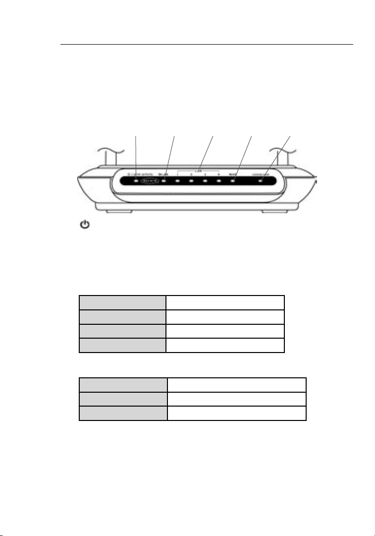
utilit y. The LED ind icators are easil y v isible on the front of t he Ro uter
to pro vide you wi th in formati on about netw ork activi ty an d s tatus.
(1) (2) (3) (4) (5)
2.4GHz • High-Speed Wireless G
1. Power/Ready/Print Activity LED
When you app ly power to the Rou ter or res tart it, a short pe riod
of time elap ses while the Ro ut er boots up . D ur ing this time , t he
LED blink s. When the Router has completely booted up, the
Power/ Ready LED bec om es a S OLID light , i ndicati ng the Router
is rea dy for use. Wh en da ta is being sent to th e p rinter, th e l ight
will blin k f ast.
OFF Router is OF F
Slow Blin king Router is Bo oting Up
Solid Router is Re ady
Fast Blin king Green Printe r A ctivity
2. WLAN: Wireless Network LED
OFF Wireless Netw ork is OFF
Solid Wireless Netw ork is Ready
Blinki ng Indica tes Wireless Acti vity
3. LAN Port-Status LEDs
These LED s a re la be led 1–4 and corres po nd to the numb ered
ports on the rear of th e R ou ter. When a comp uter is properly
connec ted to one of the LAN por ts on the rea r o f t he Router, th e
LED will lig ht. GREEN mea ns a 1 0Base-T de vi ce is connect ed,
ORANGE me ans a 100Base -T de vice is con ne cted. When
inform ation is bein g s en t o ver the por t, th e L ED blinks rap idly.
Page 13
11
Knowing Your Router
OFF No Devic e i s L in ked to the Port
Gre en 10Base -T Device Con ne cted
Orange 100Bas e-Tx Devic e C on nected
Blinki ng
(Orang e o r G reen )
4. WAN Status LED
This LED lig hts SOLID to ind ic ate that yo ur mo dem is connec ted
pro perly to the R ou ter. It blink s r apidly whe n i nf ormatio n i s b eing
sent over th e p ort betwee n t he Router and th e m od em.
OFF No WAN Li nk
Solid Good WAN Link
Blinki ng WAN Act ivity
5. Connected LED
This uniq ue LED shows you wh en the Router is co nn ected to the
Internet. When th e l ight is OFF, the Route r i s N OT co nnected to
the Inter net. Whe n t he light is blin king, the Rou te r is attemp ti ng
to connec t t o t he Inter net. When the li ght is SOLID, th e R outer
is connec ted to the Inter net. Whe n u sing the “Dis co nnect
after x minu tes” featu re, thi s L ED becomes ex trem ely useful in
monito ring the stat us of yo ur Router’s connec tion.
OFF Router is no t C onnecte d t o t he Inter net
Blinki ng Router is At temptin g t o C on nect to the
Solid Router is Co nnected to th e I nt ern et
Port Acti vity
Internet
1
2
sec tion
3
4
5
6
7
8
9
10
11
12
11
Page 14
Knowing Your Router
1312
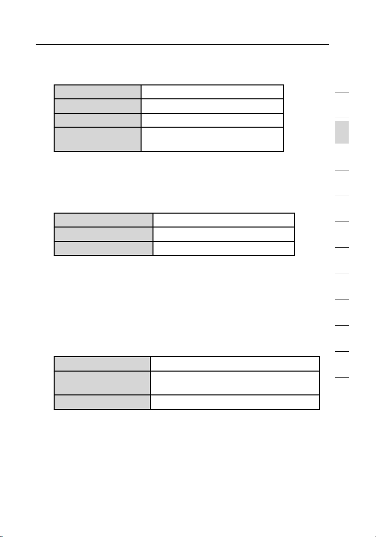
(6) (7) (8) (9)(10)
6. Power Jack - GREY
Connec t t he include d 5 V D C p ow er suppl y t o t hi s j ack.
7. Connections to Computers (LAN Ports) - BLUE
Connec t y our wired (non-wi re le ss) comput ers to these por ts.
These por ts are R J4 5, 10/100 aut o-negot ia tion, au to -uplink ing
ports for st andard UTP catego ry 5 o r 6 Et her ne t c able. The por ts
are la beled 1 through 4. Th ese ports cor resp ond to the numbe red
LEDs on the front of th e R ou ter.
8. Connection to Modem (WAN Port) - GREEN
This port is fo r c onnecti on to your cable or DS L m od em. Use the
cable tha t w as prov ided with the mo dem to connec t t he modem
to this port . U se of a c able other th an the cable sup pl ied with th e
cable mod em may not work properl y.
9. Reset Button
The Reset bu tton is used in rare cases wh en the Router ma y
functi on improperly. Resetti ng the Router wi ll rest ore t he Ro uter’s
normal op eration wh il e m aintain ing the programme d s ettings . You
can also restore the fac tory defau lt se ttings by usi ng the Reset
button . U se the res tore option in ins ta nces where you may ha ve
forgotten you r c us tom passwo rd .
a. Resetting the Router
Push and release th e R eset butto n. The lights on th e R outer
will mome ntarily fl as h. The Power/ Ready ligh t w ill begin to
blink. Wh en the Power/ Re ady light bec omes solid ag ain, the
res et is complet e.
Page 15

13
Knowing Your Router
b. Restoring the Factory Defaults
Pre ss and hold th e R es et button for at le ast ten secon ds
then release it. Th e l ights on the Rou ter will mome ntarily
flash. Th e P ower/Re ad y l ight will beg in to blink. Whe n t he
Power/ Ready ligh t b ec omes solid ag ain, the restore
is comple te.
10. USB Port - PURPLE
For USB prin ters only. See the secti on ca lled “Co nn ecting you r
printe r t o R outer’s print serv er ” o n p age 22.
1
2
sec tion
3
4
5
6
7
8
9
10
11
12
13
Page 16

Connecting and Configuring Your Router
1514
Verify the contents of your box. You should have the following:
• Belkin Wi rele ss 802.11g Ro uter
• Quick Ins tallati on Gu ide
• Belkin Ea sy Install Wi za rd So ftware CD
• RJ45 Ethe rnet Net working Ca ble (for conn ec tion of the
Router to th e c omputer )
• Power Sup ply
• User Manu al
Modem Requirements
Your c able or DSL mode m m ust be equipp ed with an RJ45 Eth er net
port. Man y m odems have bo th an RJ45 Ether net port an d a US B
connec tion. If you hav e a mo de m with both Et he rne t a nd USB, and
are us ing the USB co nn ection at thi s t ime, you will be in structe d t o
use the RJ45 Et herne t p ort during th e i nstalla ti on procedure. If your
modem has on ly a U SB port, you can reques t a di ff eren t t ype of
modem from your I SP, o r y ou can, in some cas es, purchase a mod em
that has an RJ4 5 E thern et port on it.
Ethernet USB
ALWAYS INSTALL YOUR ROUTER FIRST! IF YOU ARE INSTALLING
NUMEROUS NETWORK DEVICES FOR THE FIRST TIME, IT IS
IMPORTANT THAT YOUR ROUTER IS CONNECTED AND RUNNING
BEFORE ATTEMPTING TO INSTALL OTHER NETWORK COMPONENTS
SUCH AS NOTEBOOK CARDS AND DESKTOP CARDS.
Easy Install Wizard
Belkin ha s p rovi ded our Easy Ins tall Wizard softw are t o m ake
instal ling your Rou te r a si mple and ea sy ta sk. You ca n u se it to get
your Rout er up and runnin g i n m inutes.
The Easy Ins tall Wizard requires that you r W indows® 98 SE, Me,
2000, XP or Mac OS 9. 2x, X.1.x com puter be conn ec ted directly to
your cabl e o r D SL modem and tha t t he Inter net connec tion is activ e
Page 17

15
Connecting and Configuring Your Router
and worki ng at the time of inst allatio n. If it is no t, you must us e t he
“Alter nate Set up Method” se ction of this ma nu al to configu re yo ur
Router. A dd itional ly, if you are usin g a n o peratin g s ys tem other tha n
Window s 9 8SE, Me, 2000 , o r X P, you must set up the Ro ut er using
the “Alte rnate Se tup Method ” s ection of thi s m an ual.
IMPORTANT: R un the Easy Inst all Wizard softwa re from the
comput er that is directly con nected to the ca ble or DSL modem .
DO NOT CONNECT THE ROUTER AT THIS TIME.
Step 1 Run the Easy Install Wizard Software
Shut down an y p ro gr ams that are runni ng on your compu te r a t
1.
this time .
2. Make sure you hav e t he fo llowing it ems at the compu ter that is
now directly con nected to the ca ble or DSL modem . D O N OT
CONNEC T T HE ROUTER AT THI S T IM E.
• Quick Inst allatio n G ui de
• The Easy Inst all Wizard CD-ROM
• The Router
• The Router po wer supply
• RJ45 Ether net netw orking cab le
• This User Man ual
3. Turn off a ny fire wall or Inter net co nn ection sha ring softw are o n
your comp uter.
4. Inser t t he Easy Insta ll Wizard software CD int o y our CD–ROM
drive. Th e I nstalla ti on Menu will aut omatica lly appear on yo ur
screen within 15 se conds. If it doe s n ot, select yo ur CD-ROM
drive from “My Co mp uter” and dou ble-cli ck on the file name d
“Start .exe” on the CD- RO M.
1
2
3
sec tion
4
5
6
7
8
9
10
11
12
15
Page 18
Connecting and Configuring Your Router
1716
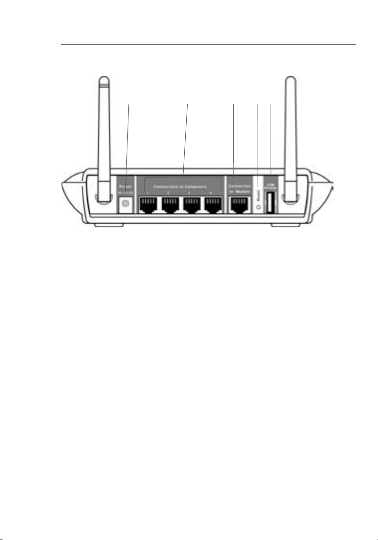
5. Clic k “ Run Router Se tup Wizard”.
Region Screen
The Regio n s cree n w ill appear. S elect your
reg ion from the dropdown box prov ided
and click “O K”.
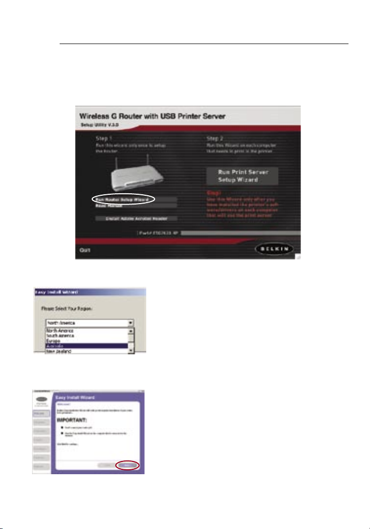
Welcome Screen
The Wizard’s w elcome scree n w ill
appear. M ak e s ure y ou have not
connec ted the Route r a t t hi s p oint. If
you have con nected you r R ou ter, pleas e
rec onnect you r c omputer di re ct ly to
the modem . C lick “Next ” w he n y ou are
rea dy to move on.
Page 19
17
Connecting and Configuring Your Router
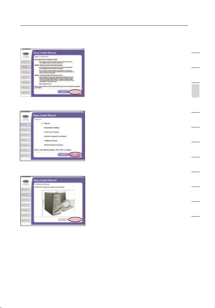
Connection Screen
The Conne ction screen will no w a ppear.
Select th e s cenario th at be st describ es
your current ADS L s etup and clic k “ Next”.
Progress Screen
Easy Inst all will show yo u a progress
screen each time a s te p i n t he setup
has been com pleted. Ea ch ti me you see
the progress screen, clic k “ Next” when
you are rea dy to move to the next st ep.
Examining Settings
The Wizard will n ow ex amine your
comput er’s net work setti ng s a nd gather
inform ation need ed to co mplete the
Router ’s conne ction to the Int er net .
When the Wiz ard i s f in ished exam ining
your comp uter, click “Ne xt” to contin ue.
1
2
3
sec tion
4
5
6
7
8
9
10
11
12
Multi-NICs Screen
If you have more tha n o ne ne twork adap ter instal led in your comp ut er
a Multi-N IC Scre en will appea r. If you have more than one net work
adapte r i nstalle d i n y ou r c omputer, t he Wizard will need to kno w
which ada pter is conne ct ed to your mod em . S elect the net work card
that is conn ected to your mo de m fro m t he list and clic k “ Next”. If you
are no t sure w hich adapt er to choose, se le ct the adap te r a t t he top of
the list. If yo u m istaken ly ch oose the wrong ada pter now, you will be
able to choo se a d iffe re nt one later.
17
Page 20
Connecting and Configuring Your Router
1918
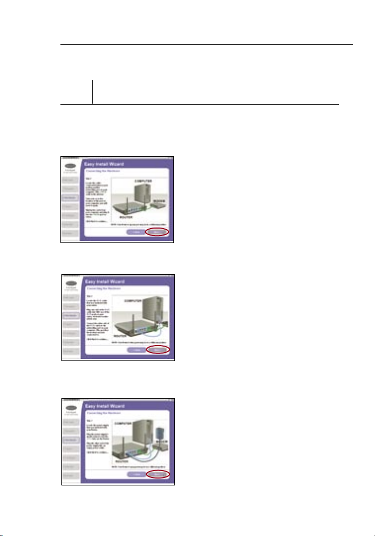
Step 2 Hardware Setup
The Wizard will w al k y ou through conn ec ting your Rou ter to your
comput er and modem. Fo ll ow the steps o n t he sc re en using the
pictures as a gui de .
2.1 Thi s s tep instru cts you to locat e
the cable co nnected be tw een your
modem and th e n etworki ng po rt on
your comp uter. Unplug th is cable
fro m t he compute r a nd plug it into
the GREEN po rt on the Router.
Click “Ne xt” to contin ue .
2.2 Thi s s tep instru cts you to locat e
the BLUE cab le that is inclu de d
with your Ro uter. Plug on e e nd
of this cabl e i nto ANY one of the
BLUE port s o n y our Router. P lu g
the other en d o f t he cable into th e
networ king port on you r c om puter.
Click “Ne xt” to contin ue .
2.3 Thi s s tep instru cts you to locat e
the power su pply that is inc lu ded
with your Ro uter. Plug th e p ow er
supply ’s small co nnector in to th e
GREY port on th e R outer. Plu g t he
power sup ply into an empt y p ow er
outlet . C lick “Next ” t o c on tinue.
Page 21
19
Connecting and Configuring Your Router
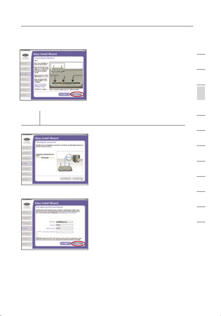
2.4 Thi s s tep instru cts you to look
at the light s o n t he fron t o f y our
Router. M ak e s ure t he appropriate
lights are ON. Re fe r t o t he Easy
Instal l s oftware on your comp uter’s
screen for more detai ls. Click
“Next” to co ntinue.
Step 3 Checking the Connection
Once you hav e c omplete d
3.1
connec ting the Rout er, t he Wizard
will chec k t he connect io n t o t he
Router an d t hen go on to determ ine
what type of In terne t c onnecti on
you have.
3.2 User Name and Password Needed
If you have a connection type that
requires a user name and a password,
the Wizard will ask you to type in
your user name and password. If your
connection type does not require a
user name and password, you will not
see this screen.
Your user name and password is provided to you by your Internet Service
Provider. If you have to type in a user name and password to connect to
the Internet, then type that same user name and password in here. Your
user name looks something like “jsmith@myisp.com” or simply “jsmith”.
The service name is optional and is very rarely required by your ISP. If you
don’t know your service name, leave this blank. When you have entered
your information, click “Next” to move on.
1
2
3
sec tion
4
5
6
7
8
9
10
11
12
19
Page 22
Connecting and Configuring Your Router
2120
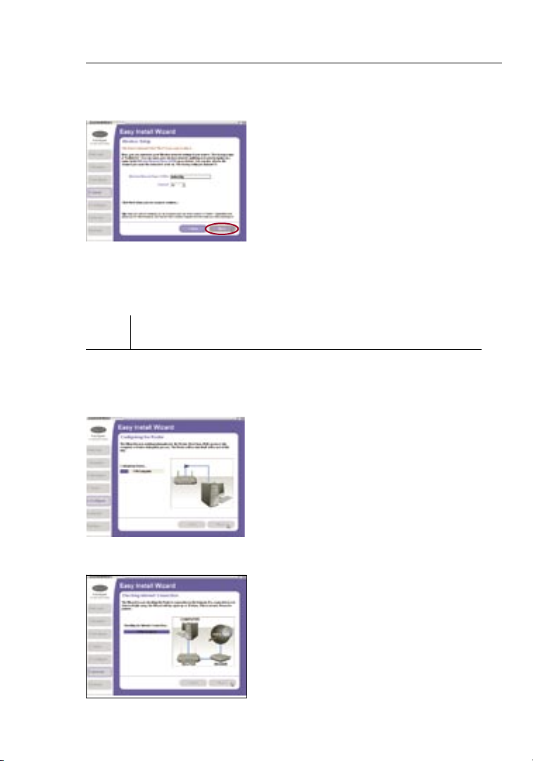
3.3 Wireless Setup
This Step Is Optional. Click “Nex t” if
you want to ski p i t.
Using thi s s tep, you can cus to mise
your wireless ne twork sett ings if
you want to. Fo llow the step s o n
the screen to com pl ete this step .
Click “Ne xt” to contin ue .
Step 4 Configuring the Router
The Wi zard will n ow tran sf er all of the co nfigura tion in formati on to the
Router. This wi ll take a pproximat el y one m inute. During th is time , do
not tu rn off th e Route r or co mp uter. T he Rout er will res ta rt itse lf at t he
end of this s te p.
4.1 Checking Internet
The Wizard will n ow ch eck for an
Internet conne ction. Thi s c an take
a few minute s. The Wizard may not
detect a con nection ri gh t a way. I f
not, it will retr y a nu mb er of times.
The “Conn ected” lig ht on th e f ro nt
panel of the Ro uter will fla sh during
this time . P lease be pati en t t hrough
this process.
Page 23
21
Connecting and Configuring Your Router
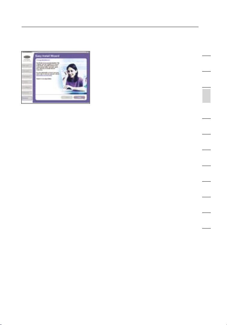
4.2 Finished
When the Int ernet co nnectio n
is comple te, the Wizard will tel l
you that you are fin is hed. The
“Conne cted” LED on the front of
the Router wil l b e SOL ID, i ndicati ng
that the Rou ter is now conne ct ed
to the Inter net.
Your Route r is no w connect ed to t he Internet. N ow you can beg in
surfin g the Int ernet by ope ni ng your b ro wser an d going t o your fa vorite
web pa ge.
Congratulations! You have fi nished in stallin g your ne w Belki n Route r.
You are ready to s et up t he othe r compu te rs in y our hom e. You can
also a dd comp ut ers to your Ro ut er any time yo u want.
1
2
3
sec tion
4
5
6
7
8
9
10
11
12
21
Page 24
Configuring and Using the USB Print Server
2322
Connecting your printer to the Router’s print server
Please closely follow the directions to set up your printer.
Before you start
Install the printer’s drivers and software on each computer from which you
plan to print. This enables the PC to print to the networked printer (printer
that is attached to your USB Print Server). Every manufacturer ships its
printer with a driver and, usually, printing software. In some cases, while
installing the drivers and software for your printer, you may be required to
connect the PC directly to the printer in order to complete the installation.
This varies according to manufacturer. You must also install the Belkin Printer
Port on each of the computers you want to print from. This may be done
using the Printer Server Setup Wizard, or can be done manually.
Start
1.
Insert the CD in to yo ur CD-ROM dri ve. Within 15 se conds, you
should se e t he install at ion menu on th e s cree n. If the menu
does not app ear within 15 se co nds, sel ec t y our CD-ROM dr ive
and view the co ntents of the dr ive. Doubl e- click on the fil e
named “St art.exe ”.
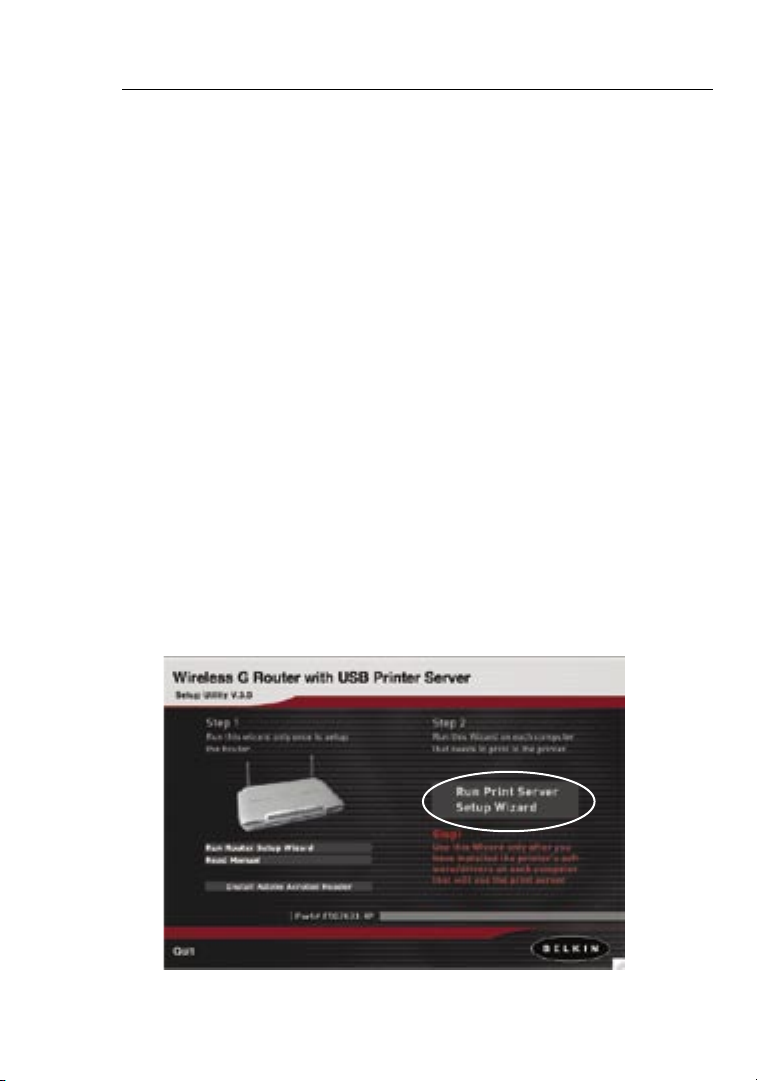
2. Fro m t he menu, cl ic k o n “ Run Print Ser ver Setup Wiz ard” . T his
will open th e P rint Serve r S et up Wizard menu.
Page 25
23
Configuring and Using the USB Print Server
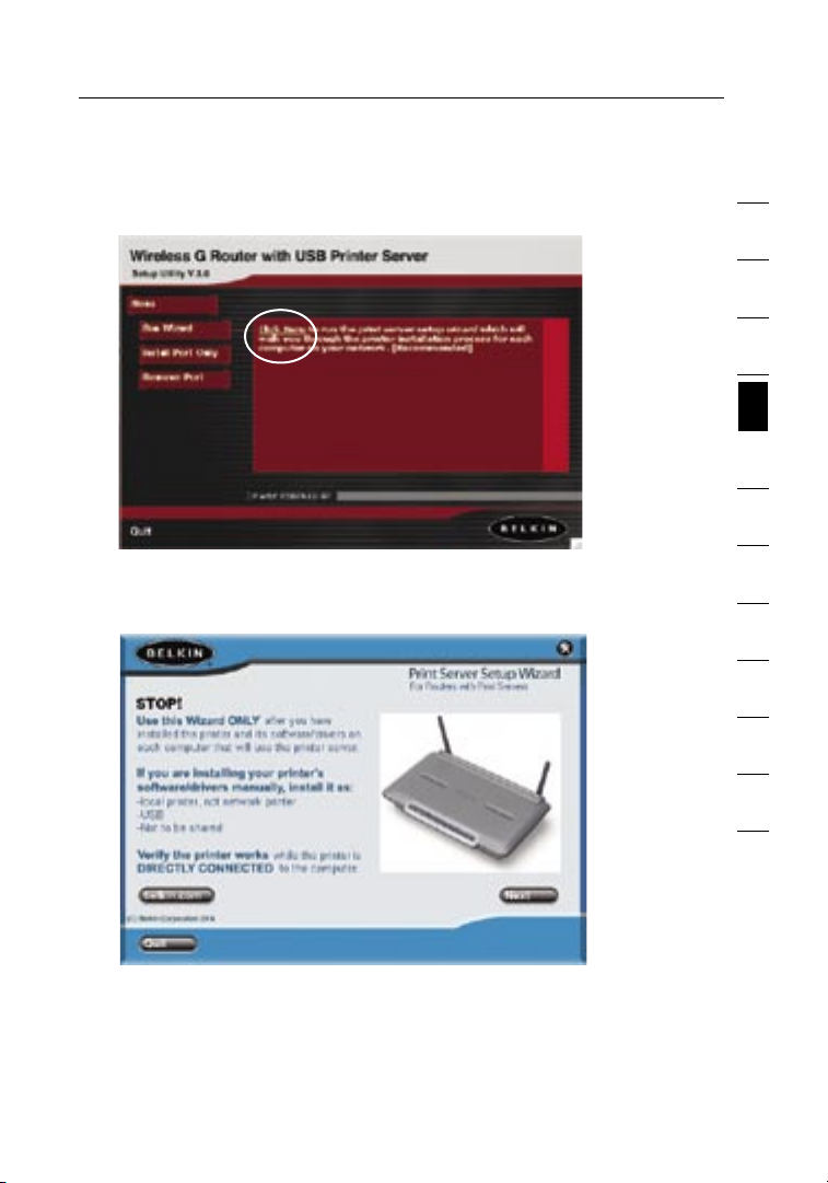
3. On the Wizard men u, dr ag your mouse ov er the “Run Wiza rd ”
button an d c lick the words “Clic k H ere” to start the Wiz ard.
4. The first sc reen of th e W izard appear s. Be su re th at you have
instal led your prin te r’s dr iv ers and softw are o n t he PCs fro m
which you pl an to print. Cli ck “Next”.
1
2
3
4
sec tion
5
6
7
8
9
10
11
12
23
Page 26
Configuring and Using the USB Print Server
2524
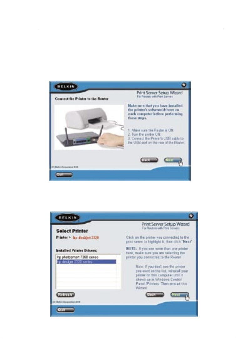
5. Next, mak e s ure t he Ro uter is ON. Make su re th e p rinter is ON.
Plug in the USB ca ble that is conn ected to the pri nt er to the USB
port on the rear of the Ro ut er. The USB port on th e R outer is
color-c od ed purple. Cl ick “Next” .
6. The Wizard will s ca n f or and locate th e P rint Serve r i n t he Router.
Next, a list of th e p rinters in stalled on th e c om puter will ap pear.
Click onc e o n t he name of the prin ter that is conn ec ted to the
Router to hi ghlight it . C li ck “Next”.
Page 27
25
Configuring and Using the USB Print Server
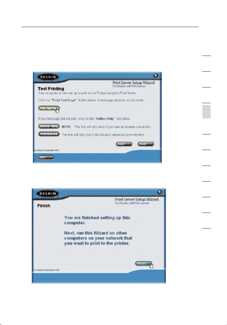
7. The next screen t ha t a ppears wil l a llow you to test pr int. Click
on the “Prin t Test Pag e” button. Wh en your test pag e i s f in ished
printi ng, click “Ne xt ”.
8. You are now fi nished set ti ng up your compu ter to print to the
Print Ser ver. Next, run t hi s W izard on the other co mp uters on
your netw ork fro m w hich you wish to pr int to this prin ter.
1
2
3
4
sec tion
5
6
7
8
9
10
11
12
25
Page 28
Configuring and Using the USB Print Server
2726
Manually installing the print server port
Advanced users can manually install the Belkin Printer Port without using the
Wizard. To do this, from the Installer menu, click “Install Printer Port Only” to
skip the Wizard. Belkin has also included a standalone installer on the CD.
From the CD, double-click on the file called “instportA.exe”.
Configuring Computers to Print to the Print Server
1.
Install Prin ter Port Soft ware on ea ch compute r b y r unning
“instp ortA.ex e” from th e C D o r b y u sing the Wiza rd.
2. Config ure the Be lkin Port Mon itor on each com puter’s printer
driver to po int to the Route r’s Prin t S er ver as foll ow s:
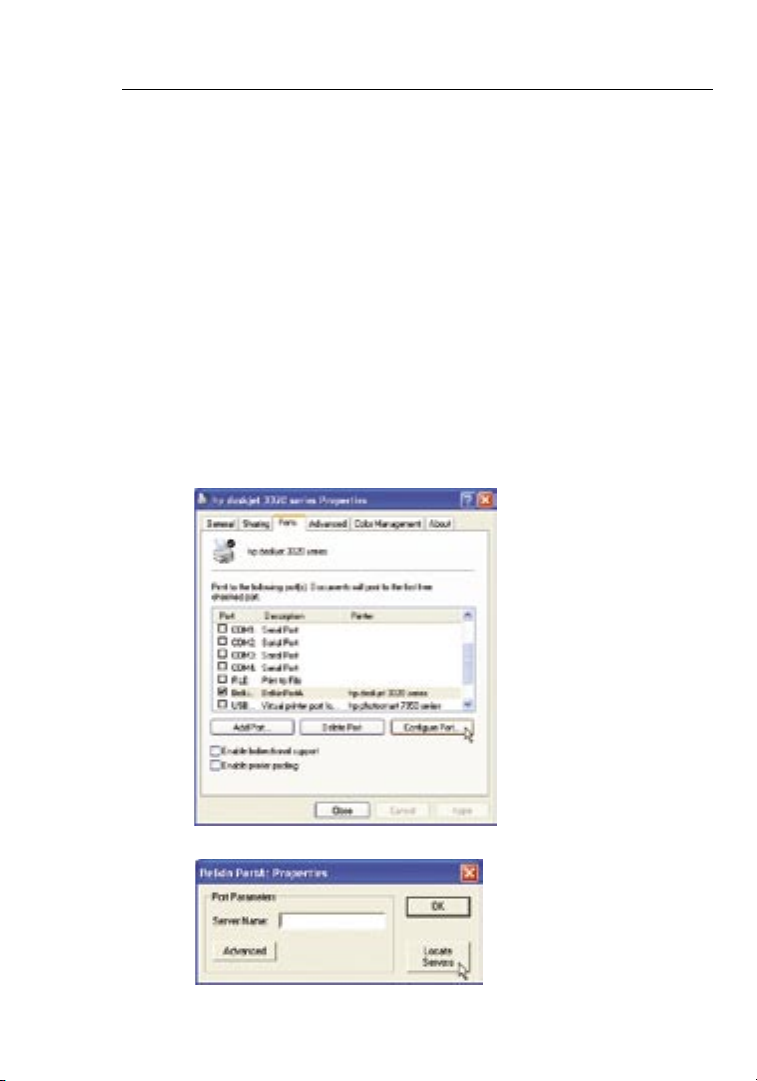
a. In Win dows, sele ct the printe r’s properti es for the print er
connec ted to the Print Se rv er and sele ct th e “ Port” tab,
select th e B elkin port , a nd cl ick “Con fi gure Port... ”
b. On the “Belkin PortA: Properties” window, click “Locate Servers”.
Page 29
27
Configuring and Using the USB Print Server
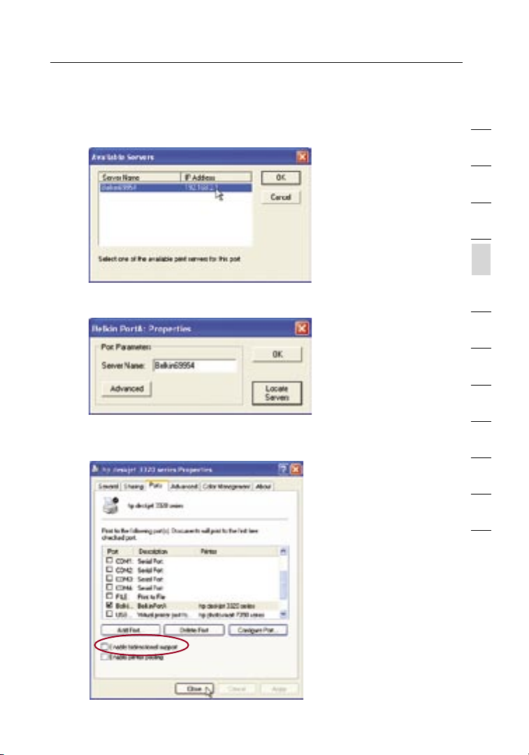
c. On the “Av ailable Se rvers” win dow, y our Router ’s print se rver
name will ap pear. Select th e P rint Serve r. Click “OK” to cl os e.
d. On the “Belki n P or t A: Pro perties ” w indow, the name of the
Print Ser ver will appe ar. C lick “OK” to clo se.
e. On the Port s t ab, unchec k t he box next to “Ena bl e b idirectio na l
suppor t” if currently chec ked. Click “A pp ly”.
1
2
3
4
sec tion
5
6
7
8
9
10
11
12
f. Click “C lose” to clos e t he window.
27
Page 30
Configuring and Using the USB Print Server
2928
Uninstalling the print server port
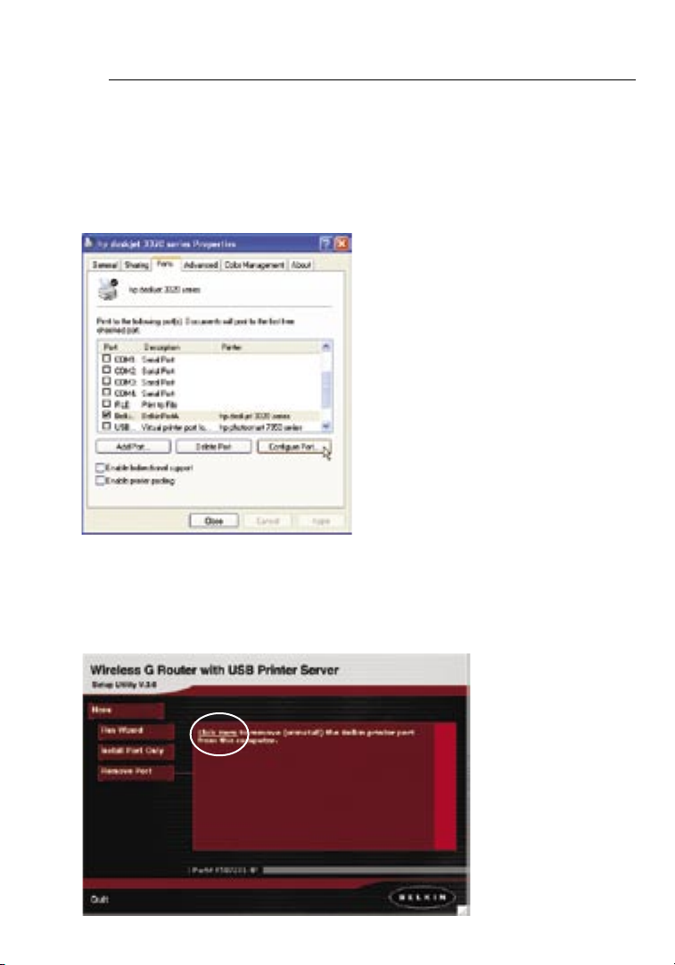
1.
In Wi ndows, s el ect the print er’s prope rt ies for the prin ter connec ted to
the Print Se rver and sele ct th e “Port” ta b, se lect the Belk in port, and cli ck
“Confi gure Po rt...”.
2. Select a different po rt from th e l ist of availa ble ports. You must sel ect a
different port bef ore you ca n rem ove the Belki n p or t.
3. Fro m t he Install er menu, clic k “ Remove Pri nter Port” to un in stall the
printe r p ort. Belki n h as al so provided an uni nstalle r a pp licatio n t hat will
rem ove the Belki n p rinter por t f ro m t he PC . Fro m t he CD, double -click on
the file cal led “rmvpo rt A.exe”. Th is will remove the pr in ter port.
Page 31

29
Configuring and Using the USB Print Server
Using the Print Server
Print Server Configuration Screen
For proper operation of the Print Server, install the printer’s drivers and
software on each computer from which you plan to print. The Belkin Print
Server Port must also be installed on each of these computers. See page 26
of this manual for more information and instructions.
The Print Server Configuration screen is the central point in the Router where
you can find the printer status (ready/not ready) and make certain adjustments.
See page 52 in this manual for directions to access the Advanced Web Based
User Interface.
(1)
(2)
(3)
(4)
(5)
1
2
3
4
sec tion
5
6
7
8
9
10
11
12
Printer field (1)
This line shows you the name of the printer that is connected to the Print
Server and its status.
Print Server Name (2)
The Print Server name identifies the Print Server. If you wish, you can
change it by typing in a new name such as “My Print Server” then clicking
“Apply Changes”.
29
Page 32

Configuring and Using the USB Print Server
3130
LPR Printing (3)
The Belkin Printer Port uses LPR as the main printing method.
Raw TCP/IP Printing (4)
This feature allows clients to print to the Print Server using the standard TCP/IP printer
port built into Windows XP and 2000, instead of the Belkin Port Monitor. Using Raw
Printing requires that you configure all port parameters manually. It is not recommended
for users unfamiliar with TCP/IP printing.
FTP Printing (5)
This feature enables the printer to receive print jobs sent by FTP (see “Using FTP Printing”
on this page). Disabling this feature will prevent FTP jobs from printing
Using FTP Printing
This section describes how to send print jobs to the printer using FTP.
1. In Window s, select the pr in ter’s prop erties.
Page 33

31
Configuring and Using the USB Print Server
2. Set the prin ter port to “Fil e” , click “Ap pl y”.
3. Print the do cument usi ng th e p rinter t ha t y ou configu re d. A
dialog ue box will open prompt ing you to name the pr int file.
After nam ing the file, cl ic k “ OK”. A file wi ll be sa ved to the use r’s
defaul t W indows directo ry (typica ll y “ C:\” or “C: \D ocument s a nd
Settin gs\<use r’s name>” ).
1
2
3
4
sec tion
5
6
7
8
9
10
11
12
31
Page 34

Configuring and Using the USB Print Server
3332
4. On the Windo ws desktop , c li ck “Start> Run” and type in “c md” for
Window s X P a nd 2000 or “comm an d” for Wind ow s 9 8SE and Me;
click “OK ” t o o pen a “Comman d/ MS-DOS P romp t” window.
5. At the prompt, type “f tp” f ollowed by th e I P a ddre ss of the Router
(defau lt is 192.168 .2 .1); press the “En te r” key to create an FTP
connec tion with the Pr in t S erver.
6. When th e c on nection is ma de, the user wil l b e p ro mpted to
enter a user na me and a password. The use r n ame for the Prin t
Server is “a nonymou s” ; t he password sho ul d be left blan k. Af ter
a success ful login, a lis t o f t he printer s c on nected to the Pr int
Server wi ll appear, foll owed by simpl e u sage instr uctions fo r h ow
to print the fi le.
Page 35

33
Configuring and Using the USB Print Server
7. At the prompt, ty pe “p ut”, follo wed by the file pat h a nd file
name, fol lowed by the pri nt er number ( fo r e xample, “p ut c:\
exampl e p rinter1 ”) .
8. The file wil l b e s ent to the Print Se rver. When the t ra nsfer is
comple te, anothe r p romp t w ill appear. I f f in ished, typ e “ quit” and
pre ss “Enter” to en d t he FTP sessio n. Then, clos e t he “Comman d
Pro mpt” windo w.
Note: FTP Printing by default is enabled in the Print Server. It can be
disabled using the Router’s Web-Based Setup Interface. See page 29
for details.
1
2
3
4
sec tion
5
6
7
8
9
10
11
12
33
Page 36

Alternate Setup Method
3534
The Advan ced User Inte rf ace is a web-b as ed tool that you ca n u se to
set up the Rout er if you don’t want to use th e E as y I nstall Wiz ard. You
can also use it to ma nage advan ced functi on s o f t he Router. From th e
Advanc ed User Inter fa ce, you can perf orm the follo wing tasks :
• Vie w t he Router’s current set tings and sta tu s.
• Config ure the Ro uter to conne ct to your ISP with th e s ettings th at
they provided yo u.
• Change th e c urre nt network se ttings suc h a s t he Inter nal IP
address, the IP a dd re ss pool, DHCP se tt ings and more.
• Set the Rout er’s firewal l t o w ork with spec ific appli cations
(port for ward ing).
• Set up secur ity features such as cl ient re stricti ons, MAC addres s
filter ing, WEP and WPA.
• Enable th e D MZ feature for a single co mputer on you r n etwork.
• Change th e R outer’s inter nal passwo rd.
• Enable /Disabl e U Pn P ( Univers al Plug-an d-Play) .
• Reset the Ro uter.
• Back up your co nfigura ti on setting s.
• Reset the Ro uter’s d efault set ti ngs.
• Update th e R outer’s firmware.
Step 1 Connecting your Router
1.1
Turn off the po we r to your mode m b y u np lugging th e p ower
supply from the m od em.
1.2 Loca te the networ k c able that is con ne cted betwe en your modem
and your com puter and unp lu g i t fro m y our comput er, l eaving the
other end co nnected to yo ur mo dem.
1.3 Plu g t he loose end of the ca ble you just unp lugged int o t he gree n
port on the bac k o f t he Router lab eled “Conn ec tion to Modem ”.
1.4 Con nect the new blu e n etwork cab le (i ncluded ) f ro m t he back of
the compu ter to one of the blue po rts labele d “ 1– 4”. Note: It does
not matte r w hich numbe red por t y ou choose.
Page 37

35
Alternate Setup Method
1.5 Tur n your cabl e o r D SL modem on by reconn ec ting the powe r
supply to th e m odem.
Mac or PC computer that was originally
connected to the cable or DSL modem
To Power Adapter
Existing networking cable
Note: Your Rout er may have port s i n d iffe re nt locatio ns th an
1.6 Bef ore p lu gging the pow er cord into the Rout er, p lug the cord
1.7 Veri fy th at your mod em is co nnected to th e R outer by chec king
1.8 Veri fy th at your compu ter is connec ted pro perly to the Rou ter
Network cable
(to computer)
depict ed in the illust ra tion above .
into the wal l, then plug the co rd into th e R outer’s power jack .
the light s o n t he fron t o f t he Router. Th e l ight label ed “WAN ”
should be ON if yo ur modem is conn ected correctl y t o t he
Router. I f i t i s n ot, rec heck your con nection s.
by checki ng the lights la be led “LAN 1, 2, 3,4”. The lig ht which
correspond s t o t he numbered por t c on nected to you r c omputer
should be ON , i f y our comput er is connect ed prop erly. If it is no t,
rec heck your con nection s.
(came with modem)
1
2
3
4
5
sec tion
6
7
8
9
10
11
12
35
Page 38

Alternate Setup Method
3736
Step 2 Set your Computer’s Network Settings to Work
with a DHCP Server
See the sect ion in this manu al called “Ma nu ally Confi guring Net work
Settin gs” for direction s.
Step 3 Configuring the Router Using the Web-Based
Advanced User Interface
Using you r I ntern et brow ser, you can acc ess the Route r’s Web-Bas ed
Advanc ed User Inter fa ce. In your browse r, ty pe “192.16 8.2.1” (yo u d o
not need to typ e i n a nything el se such as “http :/ /” or “www”). Th en
pre ss the “Enter ” k ey.
PLEASE NOTE: If yo u h ave difficul ty ac cessing th e R outer’s web-
based int erface, go to Se ct ion 7 of the user ma nu al titled “Ma nually
Config uring Comp ut er Network Se ttings” .
Logging into the Router
You wi ll see the Route r’s home pa ge in your browser wi nd ow. The
home page is vi sible to any use r w ho wants to see it. To make any
change s t o t he Router’s settin gs , y ou have to log in . C li cking the
“Login ” b utton or clic ki ng on any one of the li nk s o n t he home pag e
will take yo u t o t he login screen. The Ro uter ships wi th no password
entered. In the l og in screen, leav e t he pa ssword blank an d c lick the
“Submi t” button to log in .
Page 39

37
Alternate Setup Method
Logging out of the Router
One compu ter at a time can log in to the Ro uter for the pur poses
of making ch anges to the set ti ngs of the Rou te r. Once a user has
logged in to ma ke changes , t he re are two wa ys that the comp ut er
can be logge d o ut. Clicki ng th e “Logou t” bu tton will log th e c omputer
out. The sec ond method is au to matic. T he lo gin will time ou t a fter a
specif ied period of ti me . T he default lo gin time out is 10 min utes. This
can be chang ed from 1 t o 9 9 m in utes. For m ore inf ormatio n, se e t he
sectio n i n t his manual ti tl ed “Changi ng the Login Tim eout Setti ng”.
Understanding the Web-Based Advanced User Interface
The home pag e i s t he first page yo u w ill see when you ac cess the
Advanc ed User Inter fa ce (UI). The hom e p age shows you a qui ck view
of the Route r’s stat us and settin gs . A ll advance d s etup pages ca n b e
rea ched from this pag e.
(10) (2) (5) (4) (3)
(6)
(1)
(7)
1
2
3
4
5
sec tion
6
7
8
9
10
11
12
(9)
1. Quick-Navigation Links
You ca n g o d irectly to any of the Ro uter’s a dv anced UI pa ge s b y
clicki ng dire ctly on these li nks. The link s a re divi ded into logi cal
catego ries and grouped by tab s t o m ake findin g a pa rticula r
settin g e asier to find . C li cking on th e p ur ple header of ea ch tab
will show yo u a sh ort descri pt ion of the tab ’s funct io n.
(8)
37
Page 40

Alternate Setup Method
3938
(10) (2) (5) (4) (3)
(1)
(6)
(7)
(9)
(8)
2. Home Button
The home but ton is availa bl e i n every pag e o f t he UI . P re ssing
this butt on will take you ba ck to the home page .
3. Internet Status Indicator
This indi cator is visi bl e i n a ll pages of th e R ou ter, indic ating
the conne ction stat us of th e R outer. Whe n t he indicat or says
“conne ction OK” in GRE EN , t he Router i s c on nected to the
Internet. When th e R outer is not con nected to the In terne t, the
indica tor will read “no conne ction” in RED . T he indicat or is
automa tically up da ted when you mak e c hanges to the se ttings of
the Route r.
4. Login/Logout Button
This butt on enables yo u t o l og in and out of the Rout er with the
pre ss of one butt on . W hen you are logged in to the Router, thi s
button wi ll change to read “Logo ut”. Loggi ng into the Rout er wi ll
take you to a sepa rate login pa ge where y ou will need to ent er a
passwo rd. Whe n y ou are l ogged in to the Rou ter, you can make
change s t o t he setting s. Wh en you are finishe d m aking chan ge s,
you can log out of th e R outer by clic king the “Log ou t” button. Fo r
more i nformat ion about log ging into the Ro uter, see the sect ion
called “L ogging int o t he Ro uter”.
Page 41

39
Alternate Setup Method
5. Help Button
The “Help ” b utton give s y ou ac cess to the Ro ut er’s h el p p ages.
Help is also av ailable on ma ny pages by clic ki ng “more info” nex t
to certai n s ections of ea ch pa ge.
6. LAN Settings
Shows you th e s ettings of th e L ocal Area Network (L AN) side of
the Route r. Ch anges can b e m ad e t o t he setting s b y c licking on
any one of the lin ks (IP Address, Subn et Mask, DHCP Se rver) or
by clicki ng the “LAN” Qui ck Na vigatio n l ink on the left sid e o f
the screen.
7. Features
Shows the st atus of the Rout er ’s NAT, firewall, an d w irel ess
features. Cha nges can be made to th e s ettings by cl icking on any
one of the link s o r b y c licking th e “ Quick Navi ga tion” link s o n t he
left side of th e s cree n.
8. Internet Settings
Shows the se ttings of the In te rne t/WA N s ide of the Route r t ha t
connec ts to the Internet. Chan ges to any of these se ttings can
be made by clic king on the link s o r b y c licking on th e “ Inter net/
WAN ” Q uick Navig ation link on th e l ef t s ide of the screen.
9. Version Info
Shows the fi rmware version , b oot-cod e v er sion, ha rdwa re
versio n, and serial nu mb er of the Rout er.
10. Page Name
The page you are on can be id en tified by t hi s n ame. This man ual
will some times refer to pages by na me. For insta nce “LAN > LAN
Settin gs” ref ers to the “LAN Set tings” pag e.
1
2
3
4
5
sec tion
6
7
8
9
10
11
12
39
Page 42

Alternate Setup Method
4140
Step 4 Configuring your Router for Connection to your Internet
Service Provider (ISP)
The “Inte rnet/ WAN” ta b i s w here yo u w ill set up you r R ou ter to
connec t t o y our Internet Servi ce Prov ider (ISP) . T he Router is cap able
of connec ting to virtu al ly any ISP’s s ystem provid ed you have
correctly con figured the Rou te r’s se tt ings for your IS P’s conn ection
type. Your ISP conn ection set ti ngs are prov ided to you by yo ur IS P.
To con figure the Rout er wi th the settin gs that your ISP ga ve you,
click “Co nnectio n Type” (A) on the le ft side of the screen . S el ect
the conne ction type yo u u se . I f your ISP gav e y ou DN S s ettings ,
clicki ng “DNS” (B) allow s y ou to enter DNS add re ss en tries fo r I SP s
that require speci fic settin gs . C licking “M AC address” (C) will le t y ou
clone you r c omputer ’s MAC address or typ e i n a sp ecific WAN MAC
address, if required by your IS P. When you have fi nished mak ing
settin gs, the “Inte rnet Sta tus” indic at or will read “conn ec tion OK” if
your Rout er is set up pro perly.
(A)
(B)
(C)
Page 43

41
Alternate Setup Method
Setting your Connection Type
From the connection type page, you can select the type of connection you
use. Select the type of connection you use by clicking the button (1) next
to your connection type and then clicking “Next” (2).
(1)
1
2
3
4
5
sec tion
6
7
8
9
10
(2)
11
12
41
Page 44

Alternate Setup Method
4342
Setting your Internet Service Provider (ISP) Connection Type
to Dynamic IP
A dynamic co nnectio n t yp e i s t he most com mo n c onnecti on type
found wit h c able modem s. Se tting the c on nection ty pe to “dynami c”
in many case s i s e nough to comp lete the conn ec tion to your ISP.
Some dyna mic connec ti on types may requi re a host nam e. You c an
enter you r h ost name in the spa ce prov ided if you were assi gn ed one.
Your h ost name is assi gned by your ISP. S ome dynami c c on nection s
may re quire that you clo ne the MAC address of the PC tha t w as
origin ally conne ct ed to the modem.
(1)
(2)
(3)
1. Host Name
This spac e i s p ro vi ded to enter a host na me that needs to be
visibl e t o y our ISP. Ente r y ou r host name he re and cli ck “Apply
Change s” (3). If your ISP di d n ot as sign you a hos t n am e, or you
are no t sure, leave this bl ank.
2. Change WAN MAC Address
If your ISP requi res a spec ific MAC address to con nect to the
servic e, you can enter a spe ci fic MAC add ress or cl one the
current compu ter’s MA C a ddre ss through this li nk.
Page 45

43
Alternate Setup Method
Setting your Internet Service Provider (ISP) Connection Type
to Static IP
A static IP address connection type is less common than other connection
types. If your ISP uses static IP addressing, you will need your IP address,
subnet mask, and ISP gateway address. This information is available from
your ISP or on the paperwork that your ISP left with you. Type in your
information, then click “Apply Changes” (5). After you apply the changes,
the Internet Status indicator will read “connection OK” if your Router is set
up properly.
(1)
(2)
(3)
(4)
(5)
1
2
3
4
5
sec tion
6
7
8
9
10
11
12
1. IP Address
Pro vided by your IS P. Enter your IP ad dres s h ere.
2. Subnet Mask
Pro vided by your IS P. Enter your su bnet mask here.
3. ISP Gateway Address
Pro vided by your IS P. Enter the ISP ga teway address h ere.
4. My ISP Provides More Than One Static IP Address
If your ISP ass igns you more than one sta tic IP address, yo ur
Router is ca pable of hand li ng up to five sta ti c WAN IP ad dres ses.
Select “M y I SP prov ides more than one st at ic IP address” and
enter you r a ddition al ad dresses.
43
Page 46

Alternate Setup Method
4544
Setting your ISP connection type to PPPoE
Most DSL provide rs use PPPoE as the co nnectio n t ype. If you use a
DSL modem to co nnect to the Int ernet , y our ISP may use PPP oE to
log you into th e s ervice. If yo u h ave an Internet conne ction in your
home or smal l o ff ic e t hat doesn’t require a modem , y ou ma y also use
PPPoE.
(1)
(2)
(3)
(4)
(5)
Your connection type is PPPoE if:
a) Your ISP gave you a use r n ame and passw ord w hi ch is re quired to
connec t t o t he Inter net
b) Your ISP gave you so ftware such as Win PO ET or Enter net300 t ha t
you use to conn ect to the Inter net
or
c) You have to doubl e-click on a des ktop Icon oth er th an your
bro wser to get on th e I nt ern et
(6)
Page 47

45
Alternate Setup Method
1. User Name
This spac e i s p ro vi ded to type in your Us er name that was
assign ed by your ISP.
2. Password
Type i n y our passwo rd an d re-ty pe it into the “Ret ype Passwo rd”
box to confi rm it.
3. Service Name
A Service na me is rare ly re quired by an ISP. If you are not sure if
your ISP requires a serv ice name, lea ve th is blank.
4. MTU
The MTU sett ing should ne ve r b e change d u nl ess your ISP giv es
you a specif ic MTU settin g. Ma king cha ng es to the MTU setti ng
can cause proble ms with your Int ernet co nnectio n i ncludin g
discon nection from the Int ernet , s low Internet acces s a nd
pro blems with In ter ne t a pplicat ions worki ng prop erly.
5. Disconnect after X...
The Disco nnect feat ure is use d t o a utomati cally disc on nect the
rou ter from your ISP whe n t here is no ac tivity for a spe cified
period of ti me. For insta nc e, placing a c he ckmark nex t t o t his
option an d e ntering 5 int o t he minute fie ld wi ll cause the route r
to discon nect from the Internet after 5 m in utes of no Inter net
activi ty. This op tion shoul d b e u se d i f y ou pay for you r I nt ern et
servic e b y t he minute.
1
2
3
4
5
sec tion
6
7
8
9
10
11
12
45
Page 48

Alternate Setup Method
4746
Setting your Internet Service Provider (ISP) Connection Type to
Point-to-Point Tunneling Protocol (PPTP)
[European Cou ntries Onl y]. Some ISPs require a conn ec tion using
PPTP protocol , a ty pe of connect ion most comm on in Euro pean
countr ies. This set s u p a di rect co nnectio n t o t he ISP’s sy stem. Type
in the infor mation provide d b y y our ISP in the spac e p ro vi ded. When
you have fin ished, cli ck “A pply Chang es” (9). After you app ly th e
change s, the Internet Statu s i ndicato r w il l rea d “ connect io n O K” if
your Rout er is set up pro perly.
(1)
(2)
(3)
(4)
(5)
(6)
(7)
(8)
1. PPTP Account
Pro vided by your IS P. Enter your PP TP account na me here .
2. PPTP Password
Type i n y our passwo rd an d retyp e i t i nto the “Rety pe Password”
box to confi rm it.
3. Host Name
Pro vided by your IS P. Enter your ho st name here.
(9)
Page 49

47
Alternate Setup Method
4. Service IP Address
Pro vided by your IS P. Enter your se rvice IP address h ere.
5. My IP Address
Pro vided by your IS P. Enter the IP add re ss he re .
6. My Subnet Mask
Pro vided by your IS P. Enter the IP add re ss he re .
7. Connection ID (optional)
Pro vided by your IS P. If your ISP did not gi ve you a connect ion
ID, leave th is blank.
8. Disconnect after X….
The Disco nnect feat ure is use d t o a utomati cally disc on nect the
Router from your IS P w hen there is no activ ity for a specif ie d
period of ti me. For insta nc e, placing a c he ck mark next to thi s
option an d e ntering “5 ” i nt o t he minut e f ie ld will cause th e R outer
to discon nect from the Internet after fi ve minutes of no In ter ne t
activi ty. This op tion shoul d b e u se d i f y ou pay for you r I nt ern et
servic e b y t he minute.
1
2
3
4
5
sec tion
6
7
8
9
10
11
12
47
Page 50

Alternate Setup Method
4948
Setting your Connection Type if you are a Telstra
[Austr alia Only] Your user na me and passwo rd are provided to you by
Telstra BigPo nd. Enter thi s i nf ormatio n b elow.
Note: Your user name s hould be the same as your email address,
but with the “@bigpond.com” part removed.
Your password
for your BigPond email account.
Choosi ng your state from the drop- do wn menu (1) will au tomatic al ly
fill in your lo gin server IP ad dres s. If your login se rver address is
different than one provid ed here , you may manu al ly enter the log in
server IP ad dres s b y p lacing a chec k i n t he box next to “Use r d ecide
login ser ver manual ly ” (4) and type in the add re ss ne xt to “Logi n
Server ” (5). W hen you hav e e nt ered all of your info rm ation, c li ck
“Apply Ch anges” (7). Aft er you apply the ch anges, the In terne t S tatus
indica tor will read “conne ction OK” if you r R outer is set up properl y.
should be the same as the password you us e
®
BigPond Cable User
(1)
(2)
(3)
(4)
(5)
(7)
Note: You may have to turn your modem off for 20-40 minutes to allow
any active BigPond connections to disconnect from BigPond servers.
Page 51

49
Alternate Setup Method
1. Select your State
Select yo ur state from the drop-do wn me nu (1). The “Log in
Server ” b ox will autom at ically be fil led in with an IP addres s.
If for some reaso n t hi s a ddress does not ma tch the address
that Telstra has gi ven, you can man ually ente r t he lo gin server
address. See “Us er Decide Log in Server Man ually” (4).
2. User Name
Pro vided by your IS P. Type in yo ur user name h ere (th is should
be the same as you r e mail address, but wi th the “@bigp ond.com ”
part removed) .
3. Password
Type i n y our passwo rd an d retyp e i t i nto the “Rety pe Password”
box to confi rm it (this shou ld be the same as the pas sw ord y ou
use for your Bi gPond emai l a cc ount).
4. User Decide Login Server Manually
If your logi n s erver IP address is not av ailable in th e “ Select Your
State” drop-d own menu (1), yo u m ay ma nually ent er the login
server IP ad dres s b y p lacing a chec k i n t he box next to “Use r
decide lo gin server ma nu ally” and typ e i n t he address next to
“Login Se rver” (5).
1
2
3
4
5
sec tion
6
7
8
9
10
11
12
49
Page 52

Alternate Setup Method
5150
Setting Custom Domain Name Server (DNS) Settings
A “Domain Name Server” is a server located on the Internet that
translates Universal Resource Locator (URLs) like “www.belkin.com”
to IP addresses. Many Inter net Service Providers (ISPs) do not require
you to enter this information into the Router. The “Automatic from ISP”
box (1) should be checked if your ISP did not give you a specific DNS
address. If you are using a static IP connection type, then you may
need to enter a specific DNS address and secondary DNS address for
your connection to work properly. If your connection type is dynamic
or PPPoE, it is likely that you do not have to enter a DNS address.
Leave the “Automatic from ISP” box checked. To enter the DNS address
settings, uncheck the “Automatic from ISP” box and enter your DNS
entries in the spaces provided. Click “Apply Changes” (2) to save
the settings.
(1)
(2)
Page 53

51
Alternate Setup Method
Configuring your WAN Media Access Controller
(MAC) Address
All netwo rk compone nt s i ncludin g c ards , a dapters , a nd ro uters, hav e
a unique “se rial numbe r” ca lled a MAC add ress . Your Int ernet Se rvice
Pro vider may record the MAC a dd re ss of your compu te r’s ad ap ter and
only let tha t p articul ar co mputer con nect to the Inte rnet ser vice. When
you insta ll the Router, i ts ow n M AC address will be “s een” by the
ISP and may cau se the connec ti on not to work . B el kin has provide d
the abili ty to clone (cop y) th e MAC address of the com puter into th e
Router. T hi s M AC address, in tur n, will be see n b y t he ISP’s sy stem as
the origi nal MAC address and wil l a llow the conn ection to wor k. If you
are no t sure w hether you r I SP needs to see the or iginal MAC ad dres s,
simply cl one the MAC address of the co mputer tha t w as origina ll y
connec ted to the modem . C lo ning the ad dres s w ill not cause an y
pro blems with yo ur network .
Note: In some cases we have seen that Bi gPond Cable users have
had to clone the MAC address of the Network Card of the PC with the
BigPond softw are installed.
If you have installed the Be lkin router in place of an old router which
was co nnected to your BigPond service, you wi ll need to clon e t he MAC
address of this router’s WAN p ort (the unit’s MAC address is normally
fou nd on the underside of your ro uter, or on its config page).
Please refer to t he manufacturer’s u ser manual on how to find this
information.
1
2
3
4
5
sec tion
6
7
8
9
10
11
12
51
Page 54

Alternate Setup Method
5352
Cloning your MAC Address
To clo ne your MAC addres s, ma ke sure that you are using th e
comput er that was ORIG IN ALLY CO NNECTED to yo ur modem befo re
the Route r w as install ed . C lick the “C lo ne” button (1). Click “App ly
Change s” (3). Your MAC address is now clon ed to the Router.
Entering a Specific MAC Address
In certai n c ircu mstance s y ou may need a speci fic WAN MA C a ddre ss.
You ca n m anually en ter one in the “MAC Ad dres s” page. Type in a
MAC address in the spa ces pro vided (2) and cl ick “ Apply Chan ges” (3)
to save the cha nges. The Rou te r’s WAN MAC address wil l n ow be
change d t o t he MAC address you spec ified.
(2)
(1)
(3)
Page 55

53
Alternate Setup Method
1
2
3
4
5
sec tion
6
7
8
9
10
53
11
12
Page 56

Using the Web-Based Advanced User Interface
5554
Using you r I ntern et brow ser, you can acc ess the Route r’s Web-Bas ed
Advanc ed User Inter fa ce. In your browse r, ty pe “192.16 8.2.1” (do
not type in any thing else su ch as “http:/ /” or “w ww”) then press th e
“Enter ” k ey.
You wi ll see the Route r’s home pa ge in your browser wi nd ow.
Viewing the LAN Settings
Clicki ng on the header of th e L AN tab (1) wil l t ake you to the LAN
tab’s h eader page . A qu ick descri pt ion of the fun ct ions can be
found here. To view the set ti ngs or make ch an ges to any of the LAN
settin gs, click on “LA N S et tings” (2) or to vi ew the list of conn ected
comput ers, click on “D HC P C lient List ” (3).
(1)
(2)
(3)
Page 57

55
Using the Web-Based Advanced User Interface
Changing LAN Settings
All setti ngs for the inte rnal LAN se tup of the Route r c an be viewed
and chang ed here .
(1)
(2)
(3)
(4)
(5)
(6)
1. IP Address
The “IP address” is th e i ntern al IP address of the Rou ter. The
defaul t I P a ddre ss is “192.16 8.2.1”. To access th e a dvanced
setup int erface, ty pe th is IP address into th e a ddre ss bar of your
bro wser. This ad dres s c an be changed if ne eded. To c hange the
IP address, type in th e n ew IP address and cli ck “Apply Cha ng es”.
The IP address yo u c ho ose should be a non -routable IP.
Exampl es of a n on-routable IP are:
192.16 8.x.x (whe re x is anyth ing betwee n 0 an d 2 55)
10.x.x .x (where x i s a nything be tween 0 and 255)
2. Subnet Mask
There is no need to cha ng e t he subnet mas k. This is a unique ,
advanc ed feature of your Belk in Router. It is po ss ible to chang e
the subne t m ask if necess ar y, how ev er, do NOT ma ke changes to
the subne t m ask unless yo u h av e a specifi c reaso n t o d o s o. The
defaul t s etting is “25 5. 255.255 .0”.
1
2
3
4
5
6
sec tion
7
8
9
10
11
12
55
Page 58

Using the Web-Based Advanced User Interface
5756
3. DHCP Server
The DHCP ser ver functi on ma kes settin g u p a ne twork very ea sy
by assign ing IP addresses to eac h c omputer on th e n etwork
automa tically. The defau lt se tting is “On” . T he DHCP serve r
can be tur ned OFF if neces sary, ho wever, in order to do so you
must manu ally set a stati c I P a ddre ss for each comp uter on
your netw ork. To tu rn off the DHCP ser ver, select “Off” an d c lick
“Apply Ch anges”.
4. IP Pool
The range of IP ad dresses set aside for dynamic assignmen t to the
com puters on yo ur net work. The de fault is 2–1 00 (99 compu ters). If
you want to change this number, you can do so b y ente ring a new
sta rting and ending IP address and cl icking on “App ly Cha nges”.
The DHCP server can assign 100 I P addresses automat ically. Th is
mea ns tha t you cannot specify an IP ad dress pool larger t han 10 0
com puters. For example, starting at 50 means you have to e nd at
150 or lower so as not to exceed the 100- client limit. The starting
IP address must be lower in number than the ending IP address.
5. Lease Time
The lengt h o f t ime the DHCP ser ver will reserve the IP ad dres s
for each com puter. We rec ommend tha t y ou leave the lea se
time set to “Fo re ve r”. The defau lt setting is “F orev er”, meani ng
that any tim e a co mputer is ass igned an IP address by the
DHCP serv er, t he IP address will no t c hange for tha t p articular
comput er. S etting lea se times for sho rter inter va ls such as one
day or one hour free s I P a dd re sses after th e s pecifie d p er iod of
time. Thi s a lso means tha t a pa rticula r c om puter’s IP address
may chang e o ver time. If you ha ve set any of the othe r a dvanced
features of the R ou ter such as DMZ or cli ent IP filter s, these are
depend ent on the IP address. For th is re as on, you wil l n ot wa nt
the IP address to ch an ge.
6. Local Domain Name
The default setting is “Belkin”. You can set a local domain name
(network name) for your network. There is no need to change this
setting unless you have a specific advanced need to do so. You can
name the network anything you want such as “MY NETWORK”.
Page 59

57
Using the Web-Based Advanced User Interface
Viewing the DHCP Client List Page
You ca n v iew a list of the comp uters (kno wn as clients ), wh ich are
connec ted to your netw or k. You a re able to vi ew the IP address (1) of
the compu ter, the host na me (2) ( if the comput er has been assi gn ed
one), and th e M AC address (3) of the comp uter’s n etwork int er face
card ( NIC). Pressi ng the “Refresh” but ton will upda te the list. If the re
have been an y c hanges, th e l is t will be upda te d.
(1) (2) (3)
1
2
3
4
5
6
sec tion
7
8
9
10
11
12
57
Page 60

Using the Web-Based Advanced User Interface
5958
Configuring the Wireless Network Settings
The Wireless tab le ts you make chan ges to the wireles s n et work
settin gs. Fro m t his tab you can mak e c hanges to the wi re le ss network
name (SSI D), operat in g c hannel, en cryptio n s ecurity se tt ings, and
config ure the Ro uter to be used as an acc ess point.
Changing the Wireless Network Name (SSID)
To ide ntify your wi re le ss network , a na me called the SS ID (Servic e
Set Ident ifier) is use d. Th e d efault S SI D o f t he Router is “be lkin54g ”.
You ca n c hange this to an ything you wa nt to or you can leave it
unchan ged. If there are other wireless ne tworks ope ra ting in you r
are a, you will wa nt to ma ke sure that your SSI D i s u nique (doe s n ot
match tha t o f a nother wireles s n etwork in the area). To chan ge th e
SSID, typ e i n t he SSID that you wa nt to use in the SSID fie ld (1) a nd
click “Ap ply Change s” (2). The change is im mediate . I f y ou make a
change to th e S SID, your wireles s-equip pe d comput er s m ay also need
to be reconfigured to co nnect to your ne w n etwork nam e. Re fer to the
docume ntation of yo ur wi re less netwo rk ad apter fo r i nf ormatio n o n
making th is change.
(1)
(2)
Page 61

59
Using the Web-Based Advanced User Interface
Using the Wireless Mode Switch
Your R outer can ope rate in three different wireles s m od es: “802.1 1gAuto”, “8 02.11g- On ly”, and “802 .11g-LR S”. The different mode s a re
explai ned below.
802.11g-Auto Mode
In this mode , t he Router is com patible wi th 80 2.11b and 802 .11g
wireless clie nts simult aneousl y. This is the fa ct ory defaul t m ode and
ensures succe ssful oper ation with al l W i- Fi-comp atible dev ices. If
you have a mix of 802 .11b and 802. 11g client s i n y ou r n etwork, we
rec ommend set ting the Rout er to 802.11g -A uto mode . T hi s s etting
should on ly be changed if yo u h ave a specifi c reaso n t o d o s o.
802.11g-Only Mode
802.11 g-Only mod e w or ks with 802.1 1g clients on ly. This mo de
is rec ommende d o nly if you want to preve nt 802.11b cl ie nts from
access ing your netw or k. To sw it ch modes, s el ect the desired
mode from the “Wi rele ss Mode” drop-dow n b ox. Then, cli ck
“Apply Ch anges”.
802.11g-LRS Mode
We reco mmend you DO NOT us e t his mode unle ss you have a very
specif ic reas on to do so. This mode ex ists only to sol ve unique
pro blems that ma y o ccur with som e 8 02.11b cli ent adapte rs an d i s
NOT neces sary for inte rope rabilit y o f 8 02 .11g and 80 2. 11b standa rd s.
When to Use 802.11g-LRS Mode
In some case s, older 802. 11 b c lients m ay no t b e c ompatib le with
802.11 g w irel ess. These ad apters ten d t o b e o f i nferior de si gn and
may use olde r d rivers or tec hn ology. 8 02.11g- LRS (Limit ed Rate
Suppor t) allows the se cl ients to be co mp atible wit h t he newer
802.11 g t echnolo gy. Swit ch ing to this mode ca n s olve problem s t ha t
someti mes occur wit h t he se clients . I f y ou suspect th at you are us ing
a client ada pter that fal ls in to this cat eg ory of adapte rs, first che ck
with the ada pter vendo r t o s ee if there i s a dr iver updat e. If there
is no driver up date avail ab le, switch ing to 802.11 g-LRS mode ma y
fix your problem . Please note that switching to 802.11g-LRS mode may
decrease 802.11g performance slightly.
1
2
3
4
5
6
sec tion
7
8
9
10
11
12
59
Page 62

Using the Web-Based Advanced User Interface
6160
Using Turbo Mode
The Route r s upports Fr am e B ursting mo de.
Select ing “Frame Bu rs ting” will resu lt in all device s c ap able of
Frame Bur sting to func ti on in Frame Bu rs ting mode, an d a ll clients
not capab le, to operat e i n n or mal 802. 11 g m odes. Fram e B ursting
mode supp orts both Fra me Bu rsting- enabled de vices and non -F rame
Bursti ng-enab le d d evices sim ultaneo us ly. Fr am e Bursting mo de is
based on the un re le ased 802.1 1e specifi ca tion.
Select ing “Off” will disab le Turbo mode .
Page 63

61
Using the Web-Based Advanced User Interface
Changing the Wireless Channel
There are a nu mber of opera ting chann el s y ou can choo se from . I n
the Unite d S tates and Aus tr alia, there are 11 channe ls. In the Unite d
Kingdo m a nd most of Europe, there are 13 channe ls. In a small
number of ot her countr ie s, there are ot her channe l req uire ments.
Your R outer is conf igured to operate on th e p ro per channe ls fo r
the count ry you res ide in. The defa ult channe l i s 1 1 ( unless you are
in a country th at does not allo w c hannel 11) . T he ch annel can b e
change d i f n eeded. If the re are other wi rele ss network s o peratin g i n
your area, your n et work shoul d b e s et to operate on a cha nnel that is
different than the ot her wireless netw orks. For bes t p erformanc e, use
a channel th at is at least five ch annels awa y f rom the ot her wireless
networ k. For instan ce , i f a nother net work is opera ting on chann el 11,
then set you r n etwork to cha nn el 6 or below. To ch ange the chan nel,
select th e c hannel from the drop-d ow n l ist. Click “A pply Chang es”.
The chang e i s i mmediat e.
1
2
3
4
5
6
sec tion
7
8
9
10
11
12
61
Page 64

Using the Web-Based Advanced User Interface
6362
Using the Broadcast SSID Feature
Note: This advanced feature should be employed by advanced users only.
For secur ity, you ca n c hoose not to broadca st your netwo rk’s SSI D.
Doing so wil l k eep your netw or k name hidd en from co mputers th at
are sc anning for th e p re sence of wireless ne tworks. To turn off the
bro adcast of the SS ID, remove the che ck ma rk from the box next to
“Broadcast SS ID”, and then cl ick “Apply Ch anges”. Th e c ha nge is
immedi ate. Each com pu ter now needs to be se t t o c onnect to you r
specif ic SSID; an SSID of “A NY ” will no long er be ac cepted. Re fer to
the docum entatio n o f y ou r w ireless netw or k adapte r f or in formati on
on making th is change.
Protected Mode Switch
As part of the 802 .11g speci fi cation, Prot ected Mode en su re s p ro pe r
operat ion of 802.11 g c li ents and acce ss points whe n t here is he avy
802.11 b t raff ic in the operat ing environmen t. When Protected mo de
is ON, 802.1 1g scans for oth er wire less netwo rk traffic before it
transm its data. The refo re , u si ng this mode in env iron ments with
HEAVY 802. 11b traffic or int er ference achi ev es best perfo rmance
res ults. If you a re in an envi ro nm ent with very li ttle—or no —other
wireless netw ork traffic, yo ur be st perform ance will be ach ieved with
Pro tected mod e O FF.
Page 65

63
Using the Web-Based Advanced User Interface
Securing your Wi-Fi® Network
Here a re a few di ff eren t w ays you can maxi mise the secu ri ty of
your wireless ne twork and prote ct yo ur data from pryin g e yes and
ears. Thi s s ection is int en ded for the ho me , h ome office, and sm al l
off ice user. At the ti me of this manua l’s publ ication , t he re are three
encryp tion metho ds av ailable .
Name 64-bit Wired
Acron ym 64 -b it WEP 128-bit WE P WPA- TK IP WPA- AE S
Security G oo d B et te r Best Best
Feature s St at ic keys St at ic keys Dy na mic ke y
Equivalent
Privacy
Encryption
keys b as ed
on R C4
algorithm
(typically
40-bit k ey s)
128-bit Wired
Equivalent
Privacy
More secure
than 6 4- bi t
WEP us in g a
key le ng th of
104 bi ts plus
24 a dd it io na l
bits o f system
generated
data.
Wi-Fi Protected
Access-TKIP
encryption
and mu tu al
authenticat io n.
TKIP ( te mp or al
key in te gr it y
pro to co l)
added so
that k ey s are
rot at ed and
encryption i s
stren gt he ne d.
With Protected
Access
Dynamic ke y
encryption
and mu tu al
authenticat io n.
AES (Advanced
Encryption
Standard) does
not ca us e any
throu gh pu t
loss.
WEP (Wired Equivalent Privacy)
WEP (Wired Equiv alent Priv acy) is a common protoc ol that adds
securi ty to all Wi-Fi- co mpliant wi re le ss products. WE P w as designe d
to give wireless ne tworks the eq uivalen t l evel of priva cy prot ection as
a compara ble wired network .
1
2
3
4
5
6
sec tion
7
8
9
10
11
12
64-Bit WEP
64-bit WE P w as first introduc ed with 64-bi t e ncrypti on , w hich
includ es a k ey length of 40 bit s p lus 24 additi on al bits of
system -genera te d d ata (64 bits tot al). Some hardw are
manufa cturers ref er to 64-bi t a s 4 0- bit encryp tion. Shor tly after
the techn ology was int rodu ced, re searchers fo un d t hat 64-bit
encryp tion was too eas y
to decode .
63
Page 66

Using the Web-Based Advanced User Interface
6564
128-Bit WEP
As a re sult of 64-bi t W EP ’s pot en tial secur ity weakne sses, a more
secure method of 12 8-bit encr yption was de veloped . 1 28 -bit
encryp tion inclu de s a ke y l ength of 10 4 b it s p lus 24 additi onal
bits of syst em-gene ra ted data (128 bi ts total). So me hard ware
manufa cturers ref er to 128-b it as 10 4-bit encr yption.
Most of the new wi re le ss equipme nt in the market to day suppor ts
both 64-b it and 128-bi t W EP en cryptio n, but you might ha ve
older equ ipment tha t o nl y s upports 64 -bit WEP. All Be lkin
wireless produc ts will suppo rt bo th 64-bit and 12 8-bit WEP.
Encryption Keys
After selecting either the 64-bit or 128-bit WEP encryption mode, it is
critical that you generate an encryption key. If the encryption key is
not consistent throughout the entire wireless network, your wireless
networking devices will be unable to communicate with one another
on your network and you will not be able to successfully communicate
within your network.
You ca n e nter your key by ty ping in the hex key ma nually, or you can
type in a passp hrase in the “Pa ssphras e” fi eld and click “G enerate ”
to cre ate a key. A he x ( hexadec im al) key is a mixture of num bers and
letter s f rom A–F an d 0 –9. For 64-bi t W EP, you need to ent er 10 hex
keys. For 12 8-bit WEP, yo u n ee d to enter 26 hex ke ys .
For insta nce:
AF 0F 4B C3 D4 = 64-bit WEP key
C3 03 0F AF 0F 4B B2 C3 D4 4B C3 D4 E7 = 128-bit WEP key
The WEP pass phrase is NOT th e s ame as a WEP key. Your card uses
this pass phrase to gen er ate your WEP k ey s, but different hardware
manufa cturers might hav e d iffe re nt methods on ge ne rating the ke ys.
If you have mul tiple vend or s’ equipme nts in your netw ork, the easi est
thing to do is to use th e h ex WEP key from your Rou te r o r a ccess
point and en ter it manual ly in to the hex WEP ke y t ab le in your card’s
config uration sc reen .
Page 67

65
Using the Web-Based Advanced User Interface
WPA (Wi-Fi Protected Access)
WPA (Wi -Fi Pro tected Acc ess) is a new Wi-Fi st andard that was
design ed to improve upon the sec urity feat ures of WE P. To us e W PA
securi ty, the dri vers and soft wa re of yo ur wire less equip ment must
be upgrad ed to support WPA. These up da tes will be fo un d o n t he
wireless vend ors websit e. There a re tw o t ypes of WPA se curity, WPAPSK (no serv er) and WPA (w ith radius se rv er).
WPA-PSK (no server) use s w hat is known as a
Pre -Shared key as the Ne twork key. A N etwork key is ba sically a
passwo rd that is be tween 8 and 63 char acters lon g. It can be a
combin ation of lett er s, numbers , o r c haracte rs. Each clie nt us es
the same Net work key to acce ss th e networ k. Typi ca lly, t hi s i s t he
mode that wi ll be used in a home envi ronm ent.
WPA (with radius server) is a s ystem wh ere a radi us server
distri butes the Net wo rk key to the cli en ts automat ically. This is
typica lly found in a busi ne ss environme nt .
For a list of Belk in wire less product s t ha t support W PA, please vi sit
our websi te at www.belkin.com/networking.
1
2
3
4
5
6
sec tion
7
8
9
10
11
12
65
Page 68

Using the Web-Based Advanced User Interface
6766
Sharing the Same Network Keys
Most Wi-F i p rodu cts ship with se curity tur ned off. So once yo u h av e
your netw ork workin g, yo u n eed to acti va te WEP or WPA a nd ma ke
sure y our wireless ne tworkin g d ev ices are sharin g t he same
Networ k k ey.
Network key=
MyPassword
Network key=
MyPassword
The Wireless 802 .11g Deskt op Network Ca rd cann ot access the
networ k b ecause it is usi ng a d iffe re nt Ne twork key t ha n t he Network
key that is con figured on the Wireles s 8 02 .11g Route r.
Network key=
MyPassword
Network key=
WRONG Password
Page 69

67
Using the Web-Based Advanced User Interface
Using a Hexadecimal Key
A hexadec imal key is a mixtu re of numb ers and lette rs from A– F a nd
0–9. 64-b it keys are f ive two-di git number s. 128-bit ke ys are 13
two-di git number s.
For insta nce:
AF 0F 4B C3 D4 = 64-bit key
C3 03 0F AF 0F 4B B2 C3 D4 4B C3 D4 E7 = 128-bit key
In the boxes be low, m ake up your ke y b y w ri ting in two char acters
betwee n A –F and 0–9 in each box . You will us e t his key to program
the encry ption sett in gs on your Route r a nd your wireles s c om puters.
Note to Mac users: Or iginal App le AirPort
bit encry ption only. Apple Air Po rt 2 p ro ducts can sup port 64-bi t o r
128-bi t e ncrypti on . P lease chec k y our pro duct to see wh ic h v ersion
you are using. If yo u c an not config ure y ou r network w it h 1 28-bit
encryp tion, try 64- bi t e ncrypti on.
®
p ro du cts suppor t 6 4-
1
2
3
4
5
6
sec tion
7
8
9
10
11
12
67
Page 70

Using the Web-Based Advanced User Interface
6968
WEP Setup
64-Bit WEP Encryption
1 Sel ec t “ 64-bit WEP ” f ro m t he drop -down menu .
2. After sel ecting you r W EP en cryptio n m ode, you can ent er your
key by typin g i n t he hex key manua lly, or you ca n t ype in a
passph rase in the “Pas sp hrase” fie ld and click “Ge nerate” to
cre ate a key.
A hex (hexad ecimal) ke y i s a mi xture o f n umbers and le tters from
A–F and 0–9. Fo r 6 4-bit WEP, yo u n eed to enter 10 hex ke ys .
For instance:
AF 0F 4B C3 D4 = 64-bit WEP key
3. Click “Ap ply Change s” to fi nish. Encr yption in the Ro uter is now
set. Each of yo ur compute rs on your wireless net work will now
need to be conf igured with the same se curity set tings.
WARNING: If you are confi guring the Wi re le ss Router or Acc ess Point
fro m a computer w it h a wi re less clien t, yo u will need to en su re th at
securi ty is turne d O N f or this wireles s c li ent. If this is not do ne, you
will lose yo ur wire less conne ction.
Page 71

69
Using the Web-Based Advanced User Interface
128-Bit WEP Encryption
®
Note to Mac
Apple® A irPort®. To co nf igure encryp ti on for your Mac com puter,
set the encr yption usi ng th e m anual me th od describ ed in the
next sect ion.
1. Selec t “ 128-bit WE P” from th e d ro p-down men u.
2. After se lecting yo ur WEP encryp ti on mode, yo u c an en ter your
key manua lly by typing in th e h ex key manual ly, or you can ty pe
in a passphr ase in the “Pass ph rase” fi el d a nd click “Gen erate” to
cre ate a key.
A hex (hexad ecimal) ke y i s a mi xture o f n umbers and le tters from
A–F and 0–9. Fo r 1 28-bit WEP, y ou ne ed to enter 26 he x k ey s.
For instance:
C3 03 0F AF 0F 4B B2 C3 D4 4B C3 D4 E7 = 128-bit WEP key
users: The Pas sphrase op tion will not op er ate with
1
2
3
4
5
6
sec tion
7
8
9
10
11
12
3. Clic k “ Apply Chan ges” to finis h. Encrypt io n i n t he Router is now
set. Each of yo ur compute rs on your wireless net work will now
need to be conf igured with the same se curity set tings.
WARNING: If you are confi guring the Wi re le ss Router or Acc ess Point
fro m a computer w it h a wi re less clien t, yo u will need to en su re th at
securi ty is turne d O N f or this wireles s c li ent. If this is not do ne, you
will lose yo ur wire less conne ction.
69
Page 72

Using the Web-Based Advanced User Interface
7170
Changing the Wireless Security Settings
Your R outer is equi pped with WPA (Wireless Protec te d A ccess), th e
latest wi rele ss securit y s tandard. It also sup ports the leg acy securi ty
standa rd, WEP (W ired Equival en t P rivacy) . B y d efault, wi rele ss
securi ty is disable d. To enab le security, you must fi rs t d etermin e
which sta ndard y ou want to use. To access t he se curity set tings, cli ck
“Secur ity” on the Wireless ta b.
WPA Setup
Note: To use WPA se curity, all your clie nt s m ust be upgr ad ed to
driver s a nd software that sup port it. At the tim e o f t his manual ’s
public ation, a secu ri ty patch down load is avail able, for free, from
Microsoft. Th is patch work s o nly with the Win dows XP opera ti ng
system . You also ne ed to downloa d t he latest dri ve r f or your Belki n
Wireless 802. 11g Deskto p o r N otebook Ne tw ork Card fro m the Belki n
suppor t s ite. Other op er ating syst ems are not suppor te d a t t his time.
Microsoft’s patch onl y s upports de vices with WPA-ena bl ed drivers
such as Belk in 802.11g produc ts.
There are t wo types of WPA s ecurity : W PA-PS K ( no server) an d W PA
(with rad ius server ). WPA-P SK (n o s erver) use s a so -called PreShared key as the se cu rity key. A Pre- Shared key is a password tha t
is betwee n 8 an d 6 3 c haracte rs long. It can be a comb in ation of
letter s, numbers , a nd ot her charac ters. Each cl ient uses the sa me key
to access th e n etwork. Typica ll y, thi s m od e will be used in a hom e
environmen t.
WPA (wi th radius ser ver) is a config ur ation wherei n a ra dius serve r
distri butes the key s t o t he cl ients au to matical ly. This is ty pically us ed
in a busines s e nvironment.
Setting WPA-PSK (no server)
1.
Fro m t he “Securi ty Mode” drop-d ow n m enu, selec t “ WPA-P SK
(no serve r)”.
2. For Encry ption Techniqu e, se lect “TKIP ” o r “ AES”. This se tting
will have to be id entical on th e c lients tha t y ou se t u p.
3. Ent er your pre-sha red key. This can b e f rom 8 to 63 char acters
and can be lett ers, numbe rs , o r symbol s. Th is same key must be
used on all of the cl ients that yo u s et up. For examp le , your PSK
might be som ething lik e: “S mith famil y n etwork key ”.
Page 73

71
Using the Web-Based Advanced User Interface
4. Clic k “ Apply Chan ges” to finis h. You mus t n ow set all clien ts to
match the se setting s.
Setting WPA (with radius server) Settings
If your netw ork uses a radiu s s erver to dist ri bute keys to the cl ients,
use this set ting.
1. Fro m t he “Securi ty Mode” drop-d ow n m enu, selec t
“WPA—Radius Se rver”.
2. For Encry ption Techniqu e, se lect “TKIP ” o r “ AES”. This se tting
will have to be id entical on th e c lients tha t y ou se t u p.
3. Enter th e I P a ddress of the radi us se rver into t he “R adius
Server ” f ields.
4. Enter th e r adius key int o t he “Radius Ke y” field.
5. Enter th e k ey interva l. Key interv al is how often the ke ys are
distri buted (in pac ke ts).
6. Click “Ap ply Change s” to fi nish. You must now se t a ll cl ients to
match the se setting s.
1
2
3
4
5
6
sec tion
7
8
9
10
11
12
71
Page 74

Using the Web-Based Advanced User Interface
7372
Configuring your Belkin Wireless 802.11g Network Cards to
Use Security
Please Note:
to config ure you r B elkin Wirele ss 80 2.11g Netw ork Cards to use
securi ty.
At this poin t, you should al read y h ave your Wireless Ro uter or Acces s
Point set to us e W PA or WEP. In order fo r y ou to ga in a wireless
connec tion, you wil l n ee d t o s et your wireles s n otebook ca rd and
wireless desk top card to use the same se cu rity setti ngs.
Connecting your Computer to a Wireless Network that Requires a
64-bit or 128-bit WEP key:
Double -click the Si gn al Indicat or icon to bring up th e W irel ess
1.
Networ k s cree n. The Advanc ed button wil l a llow you to view an d
config ure more opt ions of your card.
2. Under the “W irel ess Networ k P ro pe rties” tab , s elect a netwo rk
name from the “Availa ble networ ks ” l ist and click “C onfigure”.
3. Under “Da ta Encrypt io n” select “WE P”.
4. Ensure the check bo x “ Network ke y i s p ro vi ded for me
automa tically ” a t t he bo ttom is unche cked. If you are usin g t hi s
comput er to connect to a cor po rate net wo rk, please co nsult your
networ k a dminist ra tor if this box nee ds to be checked .
5. Type y our WEP key in
the “Netw ork key” box.
Thi s sect ion is to provid e you with the information on how
Important: A WEP key is
a mixture of numb er s a nd
letter s f rom A–F an d 0 –9.
For 128-b it WEP, you need
to enter 26 key s. For
64-bit WE P, you need to
enter 10 key s. This Netwo rk
key needs to ma tch the key
you assig n t o y our Wireless
Router or Ac cess Point .
6. Cli ck “OK” to sav e
the setti ngs.
Page 75

73
Using the Web-Based Advanced User Interface
Connecting your Computer to a Wireless Network that Requires
WPA-PSK (no server)
Double-c lick the “Sig na l I ndicato r” icon to bring up th e “ Wire less
1.
Networ k” scre en. The Advan ced button wi ll allow you to vie w a nd
config ure more opt ions of your card.
2. Under th e “ Wireless Net wo rks” tab, sel ect a network na me from
the “Availabl e n etworks ” l ist and click “C onfigure”.
3. Under “N etwork Aut hentica ti on” select “W PA-PS K ( No Server) ”.
4. Type your WPA key in the “Netw or k k ey” box.
1
2
3
4
5
6
sec tion
7
8
9
10
11
12
Important: WPA-PSK is a mixture of num be rs and letter s f ro m
A–Z and 0–9. Fo r W PA-PS K y ou can enter 8 to 63 keys . T his
Networ k k ey needs to matc h t he key you assig n t o y ou r W ireless
Router or Ac cess Point .
5. Click “OK ” t o s ave the setti ng s.
73
Page 76

Using the Web-Based Advanced User Interface
7574
Connecting your Computer to a Wireless Network that Requires
WPA (with radius server)
Double-c lick the Sign al In dicator ic on to bring up the “Wi re le ss
1.
Networ k” scre en. The “Adva nced” butt on wi ll allow yo u t o v ie w
and confi gure mo re op tions of your Ca rd.
2. Under th e “ Wireless Net wo rks” tab, sel ect a network na me from
the “Availabl e n etworks ” l ist and click “C onfigure”.
3. Under “N etwork Aut hentica ti on” select WPA.
4. Under th e “ Authent ication ” t ab , s elect the s et tings that are
indica ted by your netw or k a dminist rator.
5. Click “O K” to save the sett ings.
Page 77

75
Using the Web-Based Advanced User Interface
Setting Up WPA for a Non-Belkin Wireless Desktop and
Wireless Notebook Cards
For non-B elkin WPA W irel ess Deskto p a nd Wire less Noteb ook
Cards that are not equip ped with WPA-enabl ed so ftware, a file from
Microsoft cal led “Windo ws XP Support Pa tc h for Wireless Protect ed
Access ” i s a vailabl e f or free do wnload.
Please Note: Th e f ile that Micros of t h as made avail able works on ly
with Wind ows XP. Other op er ating syst ems are no t suppor te d a t
this time .
Important: You also ne ed to ensure that the wi rele ss card
manufa cturer support s W PA and that yo u h ave downlo aded and
instal led the lates t d ri ver from their sup port site.
Suppor ted Operat in g S ystems:
• Windows XP Prof es sional
• Windows XP Ho me Edition
1
2
3
4
5
6
sec tion
7
8
9
10
11
12
75
Page 78

Using the Web-Based Advanced User Interface
7776
Setting Up Windows XP Wireless Network Utility to Use
WPA-PSK
In ord er to use WPA-PSK, ens ure you are usi ng Wi ndows Wirele ss
Networ k U tility by doi ng th e f ollowin g:
1. Under Wi ndows XP, cli ck “Start > Cont rol Pan el > N etwork
Connec tions”.
2. Right -click on “Wi rele ss Network Co nnectio n” , and selec t
“Propertie s”.
3. Click ing on the “Wirele ss Ne tworks” ta b w ill displa y t he followi ng
screen. Ensure the “U se Windows to co nf igure my wireless
networ k s ettings ” c he ck box is checke d.
Page 79

77
Using the Web-Based Advanced User Interface
4. Und er the Wireless Ne tworks tab , c li ck the “Con fi gure” button ,
and you will se e t he followi ng scre en.
5. For a home o r s ma ll busines s u ser, selec t “ WPA-P SK ” u nder
“Netwo rk Authent ic ation”.
Note: Select “WPA” if you are using this co mputer to con nect to
a corpora te network th at su pports an a ut hentica tion serve r s uc h
as a radius ser ver, pleas e c on sult your net work admin istrato r f or
furthe r i nformat io n.
6. Selec t “ TKIP” or “AES ” u nder “Data En cryptio n” . T his settin g w ill
have to be iden tical to the Rou ter that you set up .
7. Type in your enc ry ption key in the “N etwork Key ” b ox.
1
2
3
4
5
6
sec tion
7
8
9
10
11
12
Important: Enter your Pre-S ha re d k ey. This ca n b e f ro m 8 to 63
charac ters and can be let te rs, number s, or symbols . T his same key
must be used on al l o f t he clients th at you set up.
8. Click “O K” to apply sett ings.
77
Page 80

Using the Web-Based Advanced User Interface
7978
Using the Access Point Mode
Note: This advan ced feature sho ul d b e e mployed by ad vanced use rs
only. T he Router can be co nfigured to work as a wirele ss network
access po int. Using th is mo de will def ea t t he NAT IP sharin g f eature
and DHCP ser ver. In Acces s P oi nt (AP) mode, th e R outer will ne ed to
be config ured wi th an IP address that is in th e s ame subnet as th e
res t o f the netwo rk th at you will brid ge to. The defau lt IP address
is 192.16 8.2.254 an d s ub net mask is 25 5. 255.255 .0. These can be
custom ised for your ne ed .
1. Enable th e A P m ode my select in g “Enabl e” in th e “ Use as Access
Point onl y” page. When yo u s el ect this op ti on, you will be abl e t o
change th e I P s ettings .
2. Set your IP set tings to matc h y our networ k. Cl ick “Apply
Change s”.
3. Connec t a ca ble fro m t he WA N p or t o n t he Router to y ou r
existi ng network .
The Route r i s n ow acting as an acc ess point. To access th e R outer’s
advanc ed user inter fa ce again, typ e t he IP address you spe ci fied into
your browser’s naviga tion bar. You can set the enc ryption se tt ings,
MAC address filt ering, SSI D, and channe l n ormally.
Page 81

79
Using the Web-Based Advanced User Interface
Wireless Range Extension and Bridging
Wireless Rang e E xtensio n a nd Bridgin g w or ks with the fo ll owing
models on ly:
F5D723 0au4P Wireless 80 2.11g Rout er wi th Built-I n
USB Print Se rver
F5D723 1au4 High- Sp eed Mode Wirele ss 80 2.11g Rout er
F5D723 0au4 Wireless Rou ter
F5D713 0au Wireless Rang e E xtender /A ccess Poin t
Please make sure to download the latest firmware version for the Router or
Access Point for optimal performance: http://web.belkin.com/support
What is a Wireless Bridge?
A wire less bridg e i s a ctually a “mo de” in which you r W irel ess Router
can directly con nect to a second ary Wireless Acce ss Point. Not e
that you can on ly bridge you r W irel ess 802.11 g R outer (mod el
F5D723 0au4, F5D7 23 1au4P, F5D 7231au4 ) t o a Be lkin Wireless
802.11 g R ange Exten de r/Acces s P oint (mode l F 5D7130a u) . B ridging
with acce ss points of oth er ma nufactu re rs is not suppor te d a t t his
time. You can use the bri dge mode to exte nd the range of you r
wireless netw ork, or add an exte nsion of your ne twork in anot he r a re a
of your office or ho me wi thout runn ing cables .
Range Extension
Range ext ension wil l e xt end the wireles s c overage area in your ho me
or off ice. The ex am ple on the next pag e i llustra tes use of bridg in g to
extend th e r ange of your wireles s n etwork. In th is example , t he Ro uter
is set up to conne ct to an Access Poi nt located in an ot her area.
Laptop s c an roam , o r m ove betwee n t he two wireless co ve rage areas.
1
2
3
4
5
6
sec tion
7
8
9
10
11
12
79
Page 82

Using the Web-Based Advanced User Interface
8180
Adding Another Network Segment Wirelessly
Bridgi ng an Access Poi nt to yo ur Wireless Rou ter allows yo u t o a dd
anothe r n et work segme nt in another area in the hom e o r offic e w it hout
runnin g w ires . C onnecti ng a n etwork swi tc h or hub to the Acce ss
Point’s RJ45 jack wi ll allow a numbe r o f c omputer s c on nected to the
switch ac cess to the rest of the netwo rk.
Page 83

81
Using the Web-Based Advanced User Interface
FCC ID: K7SF5D7130A
model # F5D7131
Wireless
Range Extender/
Access Point
IC: 3623A-F5D7130A
Complies with Canada RSS-210
P81807
F5D7131
WLAN MAC Address
Serial #
LAN MAC Address
Setting Up a Bridge Between your Wireless Router and a
Secondary Access Point
Bridgi ng your Belki n R ou ter to a secon da ry Access Poi nt re qu ires that
you acces s t he Router’s Advanc ed Se tup Utilit y a nd enter the MAC
address of the Ac ce ss Point in the app ro pr iate area. There are also a
few other requirem ents. PLEASE BE SURE TO FOLLOW THE STEPS BELOW,
CAREFULLY.
1. Set your Ac cess Point to th e s ame channe l a s t he Router. By
defaul t, the Router an d A cc ess Point c ha nnels are set to chan ne l
11 at the facto ry. If you hav e n ever chang ed the channe l, yo u
don’t need to do any th ing (for more info rm ation on ch an ging
channe ls, see page 47 of thi s m anual).
2. Find the Ac cess Point ’s MAC addres s o n t he bo ttom of the
Access Po int. There are two MAC addresses on th e b ottom labe l.
You wi ll need the MAC add re ss na med “WLAN M AC Ad dress”.
The MAC address s ta rts with 0030 BD or 001150 and is fo llowed
by six other nu mbers or lett er s (i.e. 003 0B D-XXXXX X). Wri te the
MAC address belo w. G o t o t he next step.
0030BD-XXXX XX
3. Pl ace your seco ndary Acce ss Point with in ra nge of your Wi rele ss
Router an d n ear the area where you want to ext end the range
or add the netw ork segmen t. Typi cally, i nd oor rang e s ho uld be
betwee n 3 0 a nd 60 metres.
4. Conne ct power to your Ac cess Point . M ake sure t he Access Poi nt
is on and proceed to th e n ex t s tep.
1
2
3
4
5
6
sec tion
7
8
9
10
11
12
81
Page 84

Using the Web-Based Advanced User Interface
8382
5. From a comput er alre ady connec ted to your Rout er, a ccess the
Advanc ed Setup Util it y b y o pening you r b ro wser. In the address
bar, type in “1 92 .168.2. 1”. Do not type in “ww w” or “http:/ /”
before the numbe r. Note: If you ha ve changed yo ur Router’s IP
address, use tha t I P a ddress.
6. You will see the Ro ut er’s u se r i nterfac e i n t he browser wind ow.
Click “Wi rele ss Bridge” (2) o n t he left-ha nd si de of the screen.
You wi ll see the follo wing screen.
(1)
(2)
(3)
7. Check th e b ox that says “En able ONLY specifi c A ccess Poin ts to
connec t” (1).
8. In the fiel d n amed AP1 (3), ty pe in the MAC address of your
second ary Access Po in t. When you have ty ped in the address ,
click “Ap ply Change s” .
9. Bridg ing is now set up.
Page 85

83
Using the Web-Based Advanced User Interface
Configuring the Firewall
Your R outer is equi pped with a firewall th at will protect yo ur ne twork
fro m a wide array of co mm on hacker att acks inclu ding:
• IP Spoofin g
• SYN flood
• Land Attac k
• UDP floodi ng
• Ping of Death (P oD)
• Tear Drop At tack
• Denial of Ser vice (DoS)
• ICMP defec t
• IP with zero lengt h
• RIP defect
• Smurf Atta ck
• Fragmen t f looding
• TCP Null Scan
The firewall also masks c ommon ports that are f reque ntly used to
att ack ne tworks. These ports appear to be “Stealth”, me aning that for
all inten ts and purposes, the y do not exist to a would-be hacker. You
can turn t he firewall functio n off if needed, howev er, it is reco mmended
tha t you leave the firewa ll ena bled. Disabling the firewall protectio n will
not leave your network comple tely v ulnerable to hacker attacks, but it
is re commended that you l eave t he firewall enabled .
1
2
3
4
5
6
sec tion
7
8
9
10
11
12
83
Page 86

Using the Web-Based Advanced User Interface
8584
Configuring Internal Forwarding Settings
The Virtual Servers function will allow you to route external ( Internet)
cal ls for services such as a web serve r (por t 80), FTP server (Port 21),
or other applications throug h your Router to your i nter nal ne twork.
Sin ce you r internal compute rs are p rotecte d by a fi rewall, computers
out side y our network (over th e Inte rnet ) cannot get to them be cause
the y cann ot be “seen.” A list of commo n appl ications has b een
provided in case you need to configure the Virtual Server function for
a specifi c application. If yo ur app lication is not list ed, yo u will need to
con tact t he application vendor to f ind out which port setting s you need.
Choosing an Application
Sel ect yo ur application from the drop-down l ist. C lick “Add”. The
set tings will be transferred to the n ext available space in the screen.
Cli ck “Ap ply Changes” to save the setting for that applicatio n. To
remove an application, selec t the number of the row t hat yo u want to
remove then click “Clear”.
Manually Entering Settings into the Virtual Server
To manually enter settings, enter the IP ad dress in the spa ce provided
for the internal (server) machine , the port(s) require d to pass, select the
por t type (TCP or UDP), and clic k “App ly Cha nges”. Each in bound port
ent ry has two fields with 5 char acters maximum per field t hat al lows a
sta rt and end port range, e.g. [ xxxxx]-[xxxxx]. For eac h entr y, you can
ent er a single port value by fil ling i n the two fields with the sam e valu e
(e. g. [75 00]-[7500] or a wide range of ports (e.g. [7500]-[90 00]). If you
nee d mult iple single port val ue or mixture of range s and a s ingle value,
you must use multiple entries up to th e maxi mum of 20 entries (e.g.
1. [7500] -[7500], 2. [8023]-[802 3], 3. [9000]- [9000]). You can only pass
one port per internal IP address. Opening ports in your fi rewal l can
pos e a security risk. You can enable and disable settings very quickl y.
It is recommended that yo u disa ble th e settings whe n you are not using
a specifi c application.
Page 87

85
Using the Web-Based Advanced User Interface
Setting Client IP Filters
The Route r can be configured to restrict access to th e Inte rnet , e-mail,
or other networ k serv ices a t spec ific d ays an d time s. Res triction can be
set for a si ngle c omputer, a range of comput ers, o r multiple computers.
To restric t Internet access to a sing le com puter for example, e nter t he
IP address of the compute r you wish to restrict acces s to in t he IP
fie lds (1). Next, enter “80” in both the port f ields (2). Select “Both” (3).
Sel ect “B lock” (4). You can also select “Always” to block access all
of the time. Select the day to start on t op (5), the time to start on
top (6), the day to e nd on the bottom (7), and the time to stop (8) on
the botto m. Select “Enable” (9). Click “Apply Changes”. The compute r
at the IP ad dress you specified will now be blocked from Internet
acc ess at the times you specified. Note: Be sure y ou hav e sele cted the
cor rect time zone under “ Utilities> System Setti ngs> T ime Zone”.
1
2
3
4
5
6
sec tion
7
8
9
10
11
12
(1) (2)
(5)
(4) (7) (8) (9)
(3)
85
(6)
Page 88

Using the Web-Based Advanced User Interface
8786
Setting MAC Address Filtering
The MAC address filter is a powerful security featu re that allows you
to specif y which computers are allowed on the netwo rk. An y comp uter
att empting to access the netw ork th at is not specified in the fi lter l ist
wil l be denied access. When you enable this feature , you must enter
the MAC address of each client (compu ter) on your network to allow
net work a ccess to each. The “Block” feature lets yo u turn on and off
acc ess to the network easily for any c omputer without having to add
and remove the computer’s MAC address from the list.
(1)
(2)
(3)
To enable t his fe ature, select “Enab le MAC Address F iltering” (1).
Nex t, ent er the MAC addre ss of each computer on your network by
cli cking in the space pro vided (2) and e ntering the MAC address of
the compu ter you want to add to the list. Click “Add” (3), then “Apply
Cha nges” to save the settings . To del ete a MAC address from t he lis t,
sim ply cl ick “Delete” next to the MAC address you wish to de lete. Click
“Ap ply Ch anges” to save the setting s.
Note: You will not be able t o dele te the MAC addre ss of the computer
you are using to access the Router’s administra tive functions (the
com puter you are using no w).
Page 89

87
Using the Web-Based Advanced User Interface
Enabling the Demilitarised Zone (DMZ)
The DMZ feature allows yo u to specify one computer on your n etwork
to be placed outside of the firewall. This may be necessary if the
firewall is causing prob lems with an applica tion s uch as a game or
vid eo con ferenci ng app lication. Use this f eature on a temporary basis.
The compu ter in the DMZ is NOT pro tected from hacker attack s.
To put a computer in the D MZ, enter the last digits of its IP address in
the IP field and s elect “Enable”. Click “Apply Changes” for the change
to take effect. If you are using multiple stati c WAN IP addresses, it is
pos sible to select which WAN IP address the D MZ hos t will be direct ed
to. Type in the WAN IP address yo u wish the DMZ host to direct t o,
ent er the last two digits of the IP address of the DMZ host com puter,
sel ect “E nable” and click “Ap ply Ch anges”.
1
2
3
4
5
6
sec tion
7
8
9
10
11
12
87
Page 90

Using the Web-Based Advanced User Interface
8988
Blocking an ICMP Ping
Com puter hackers use what is known as “pinging” to find po tential
vic tims o n the Internet. By pinging a spec ific I P address and receiving
a res ponse from the I P address, a hacker can dete rmine that something
of interest might be there. The R outer can be set up so it will n ot
respond to an ICMP ping fro m the outside. This height ens th e level of
sec urity of your Router.
(1)
To turn off the ping response, se lect “ Block ICMP Ping” (1) and click
“Ap ply Ch anges”. The Router w ill no t respond to an ICMP ping.
Page 91

89
Using the Web-Based Advanced User Interface
Utilities Tab
Thi s screen lets you mana ge different pa rameters of the Router and
per form c ertain administra tive f unctions.
Parental Control
See separ ate Parental Control User Manual from Belkin.
1
2
3
4
5
6
sec tion
7
8
9
10
11
12
89
Page 92

Using the Web-Based Advanced User Interface
9190
Restarting the Router
Someti mes it may be neces sa ry to re start or reboot th e R ou ter if it
begins wo rking improper ly. Rest arting or rebooti ng the Router wi ll
NOT delet e a ny of your confi gu ration s et tings.
Restarting the Router to Restore Normal Operation
Click the “Res tart
1.
Router ” b utton.
2. The foll owing mess age
will appe ar. C lick “OK”.
3. The foll owing mess age
will appe ar. R estarti ng
the Route r c an take
up to 60 second s. It is
import ant not to tur n o ff
the power to th e R outer
during th e resta rt.
4. A 60-seco nd countdo wn wi ll appear on t he sc re en. When the
countd own rea ches zero, the Rou te r w ill be restarte d. The Router
home page sh ould appea r a ut omatica lly. If not , t ype in the
Router ’s address (def ault = 192.16 8.2.1) int o t he navigatio n b ar of
your browser.
Page 93

91
Using the Web-Based Advanced User Interface
Restoring Factory Default Settings
Using thi s o ption will restore all of th e s ettings in th e R ou ter to the
factor y ( default ) s et tings. It is recom me nded tha t y ou ba ck up your
settin gs before you restore all of the defau lts.
1. Click th e “ Restore
Defaul ts” button .
2. The foll owing mess age
will appe ar. C lick “OK”.
3. The foll owing mess age
will appe ar. R estorin g
the defau lts includ es
res tarting th e R outer.
It can take up to 60
second s. It is importa nt
not to tur n t he power
to the Route r o ff du ri ng
the re start.
4. A 60-sec ond countd own will appe ar on the screen. When the
countd own rea ches zero, the Rou te r’s de fa ults will be resto red.
The Route r h ome page shou ld ap pear aut om aticall y. If it does
not, type in th e R outer’s address (defau lt = 1 92.168. 2.1) into the
naviga tion bar of your browse r.
1
2
3
4
5
6
sec tion
7
8
9
10
11
12
91
Page 94

Using the Web-Based Advanced User Interface
9392
Saving a Current Configuration
You ca n s ave your curren t c on figurat ion by using thi s f eature. Saving
your conf igurati on wi ll allow you to resto re it late r i f y our settin gs are
lost or chan ged. It is re commend ed that you back up yo ur current
config uration be fo re pe rformin g a fi rm ware update.
1. Click “S ave”. A windo w
called “F ile Downlo ad ”
will open . C lick “Save ”.
2. A window wi ll open
that allo ws you to
select th e l ocation
where you want to
save the con figurat io n
file. Sel ect a locatio n.
You ca n n ame the file
anythi ng you want, or
use the defa ult name
“Confi g”. Be sure t o
name the fil e s o y ou
can locat e i t y ourself
later. Wh en yo u h ave
select ed the locati on
and name of the fi le,
click “Sa ve”.
Page 95

93
Using the Web-Based Advanced User Interface
3. When the sav e i s
comple te, you will see
the follo wing windo w.
Click “Cl ose”.
The con figurat io n i s
now saved .
Restoring a Previous Configuration
This opti on will allow yo u t o resto re a previou sly saved con figurat io n.
1. Click “Browse ”. A w indow will op en that allow s y ou to select the
locati on of the config ur ation file . A ll configu ration fil es en d with
a “.bin”. Lo cate the conf ig uration fi le you want to restore and
double -click on it.
1
2
3
4
5
6
sec tion
7
8
9
10
11
12
93
Page 96

Using the Web-Based Advanced User Interface
9594
2. You wil l b e a sked if you want to co ntinue. Cl ic k “ OK”.
3. A re mi nder windo w w ill appear. I t w ill take up to 60 seco nds for
the confi guratio n resto ration to com pl ete. Click “O K”.
4. A 60-seco nd countdo wn wi ll appear on t he sc re en. When the
countd own rea ches zero, the Rou te r’s co nf igurati on will be
res tored. The Rout er home page sho ul d a ppear auto matical ly. If
not, type in th e R outer’s address (defau lt = 1 92.168. 2.1) into the
naviga tion bar of your browse r.
Page 97

95
Using the Web-Based Advanced User Interface
Updating the Firmware
Fro m t ime to time , B el kin may release ne w v ersions of th e R ou ter’s
firmwa re. Fir mware update s c on tain featu re im prov ements and fi xe s
to pro blems that ma y e xist. When Be lkin re leases new fi rmware,
you can down load the firm wa re from th e B el kin update we bsite and
update yo ur Router’s firmwa re to the lat est versio n.
(1)
Checking for a New Version of Firmware
The “Chec k F irmware” (1) button all ow s y ou to instant ly check for a
new versi on of firmware. When yo u c lick the butt on, a new bro wser
window wi ll appear inf or ming you that ei ther no new firm ware is
availa ble or that there is a new versi on availab le. If a new versio n i s
availa ble, you will ha ve th e o ption to do wn load it.
1
2
3
4
5
6
sec tion
7
8
9
10
11
12
95
Page 98

Using the Web-Based Advanced User Interface
9796
Downloading a New Version of Firmware
If you click th e “ Check Firm wa re ” b utton and a new ver sion of
firmwa re is avai lable, you wi ll see a scre en such as the fo ll owing.
1. To dow nload the new ve rsion of firm ware , c lick “Down load”.
2. A window wil l o pen that allo ws you to select th e l oc ation where
you want to sav e t he firmware file. Se lect a locati on. You ca n
name the fil e a nything yo u w an t, or use the def au lt name. Be
sure t o save the fil e i n a pl ac e w here you can locat e i t y ourself
later. Note: We s uggest sav ing this to your de sk top to loca te th e
file easi ly. When yo u h ave select ed th e l ocation , c lick “Save ”.
Page 99

97
Using the Web-Based Advanced User Interface
3. When the sav e i s c omplete , y ou will see the fol lo wing windo w.
Click “Cl ose”.
The downl oad of the firmw are is com plete. To update the fi rmware,
follow th e n ext steps in “Up da ting the Ro ut er’s F ir mware”.
Updating the Router’s Firmware
1. In the “Firm ware
Update ” p age, click
“Browse”. A wind ow
will open th at allows
you to selec t t he
locati on of the firmwa re
update fi le.
2. Bro wse to the fir mw are
file you dow nloaded .
Select th e f ile by
double -clicki ng on th e
file name .
1
2
3
4
5
6
sec tion
7
8
9
10
11
12
97
Page 100

Using the Web-Based Advanced User Interface
9998
3. The “Upda te Firmware”
box will now di splay
the locat ion and name
of the firmw are f il e y ou
just sele cted. Clic k
“Updat e”.
4. You will be aske d i f y ou
are su re yo u w ant to
contin ue. Click “OK ”.
5. You will see one mo re
messag e. This messa ge
tells you that the Router
may not respond f or as
long as one min ute as
the firmw are is l oa ded
into the Rou ter and
the Route r i s reb oo ted.
Click “OK ”.
6. A 60-sec ond countd own will appe ar on the screen. When the
countd own rea ches zero, the Rou te r f irmware upda te wi ll be
comple te. The Route r h om e p age should ap pear autom aticall y. If
not, type in th e R outer’s address (defau lt = 1 92.168. 2.1) into the
naviga tion bar of your browse r.
The firmware update is complete!
 Loading...