

Page 1

Wireless G
Router
User Manual
F5D7230-4
Page 2

Table of Contents
1. Introduction . . . . . . . . . . . . . . . . . . . . . . . . . . . . . . . . . . . . . 1
Benefits of a Home Network . . . . . . . . . . . . . . . . . . . . . . . . .
Advantages of a Wireless Network . . . . . . . . . . . . . . . . . . . .
Placement of your Router for Optimal Performance . . . . . . .
2. Product Overview . . . . . . . . . . . . . . . . . . . . . . . . . . . . . . . . .
Product Features . . . . . . . . . . . . . . . . . . . . . . . . . . . . . . . . .
3. Knowing your Router . . . . . . . . . . . . . . . . . . . . . . . . . . . . . .
Package Contents . . . . . . . . . . . . . . . . . . . . . . . . . . . . . . . .
System Requirements . . . . . . . . . . . . . . . . . . . . . . . . . . . . . .
Easy Install Wizard Software System Requirements . . . . . . .
4. Connecting and Configuring your Router . . . . . . . . . . . . . . 14
5. Alternate Setup Method . . . . . . . . . . . . . . . . . . . . . . . . . .
6. Using the Web-Based Advanced User Interface
Changing LAN Settings. . . . . . . . . . . . . . . . . . . . . . . . . . . . 43
Viewing the DHCP Client List Page . . . . . . . . . . . . . . . . . . 45
Configuring the Wireless Network Settings. . . . . . . . . . . . . 46
Securing your Wi-Fi Network . . . . . . . . . . . . . . . . . . . . . . . 50
WEP Setup . . . . . . . . . . . . . . . . . . . . . . . . . . . . . . . . . . 55
WPA Setup . . . . . . . . . . . . . . . . . . . . . . . . . . . . . . . . . . 59
Setting WPA/WPA2 . . . . . . . . . . . . . . . . . . . . . . . . . . . . 60
Guest Access (Optional) . . . . . . . . . . . . . . . . . . . . . . . . 61
Using the Access Point Mode. . . . . . . . . . . . . . . . . . . . . . . 65
Configuring the Firewall . . . . . . . . . . . . . . . . . . . . . . . . . . . 70
Setting MAC Address Filtering . . . . . . . . . . . . . . . . . . . . . . 73
Enabling the DMZ . . . . . . . . . . . . . . . . . . . . . . . . . . . . . . . . 74
Utilities Tab . . . . . . . . . . . . . . . . . . . . . . . . . . . . . . . . . . . . 76
Restarting the Router. . . . . . . . . . . . . . . . . . . . . . . . . . . 77
Updating the Firmware . . . . . . . . . . . . . . . . . . . . . . . . . 82
7. Manually Configuring Network Settings . . . . . . . . . . . . . . 90
8. Recommended Web Browser Settings . . . . . . . . . . . . . . . . 96
9.
Troubleshooting . . . . . . . . . . . . . . . . . . . . . . . . . . . . . . . . . 98
10.
Information . . . . . . . . . . . . . . . . . . . . . . . . . . . . . . . . . . . 117
. . . . . . . . . 42
24
1
1
2
6
6
9
9
9
9
Page 3

Introduction
Thank you fo r p urchasing the Be lki n Wireless G Router (t he Router).
The followin g t wo short section s d iscuss the benefits of home
networking a nd outline best pra cti ces for maximizing you r wireless
home network ra nge and performa nce . Please be sure to re ad through
this User Ma nua l completely, an d p ay special attentio n t o the section
entitled “Pl ace ment of your Rou ter for Optimal Perfor man ce” on
page 2.
Benefits of a Home Network
• Share one h igh-speed In ternet co nne ction wit h all the c omp uters in
your home
• Share resources, such a s files and hard dri ves among all the
connected computers in you r home
• Share a sin gle print er with the en tire fami ly
• Share documents, music, video, a nd digita l pictures
• Store, retrieve, and co py files from one co mpu ter to another
• Simult ane ously pla y games online, c heck I nte rnet emai l, and chat
Advantages of a Wireless Network
Mo bility – you no lon ger need a dedicate d “ computer
room”—now yo u c an work on a net wor ked laptop or deskt op computer
anywhere wit hin your wireless r ang e
Ea sy installation – T he Belkin Easy Inst all ation Wizard makes
setup simple
Fl exibility – set up and access printers , c omputers, and other
networking d evi ces from anywher e i n your home
Ea sy expansion – t he wide range of Belki n n etworking products let
you expand y our network to incl ude devices such as pr int ers and
gaming conso les
No cabling require d – you can spare the exp ense and hassle of
retrofitting Et hernet cabling t hro ughout the home or off ice
Widespread i ndu stry acceptance – c hoose from a wide r ang e of
interoperabl e n etworking produc ts
sec tion
1
2
3
4
5
6
7
8
9
10
1
Page 4

Introduction
Placement of your Router for Optimal Performance
Important Factors for Placement and Setup
Your wireles s c onnection will b e s tronger the closer you r computer is
to your Rout er. Typical indoor ope rating range for wi rel ess devices is
between 100 and 200 feet.
In the same way , your wireless con nection and perform anc e will
degrade some wha t as the distanc e b etween your Router and
connected de vic es increases. Th is may or may not be n oti ceable
to you. As y ou move farther fro m y our Router, connect ion speed
may decrease . F actors that can wea ken signals simply by getting
in the way o f y our network’s ra dio waves are metal ap pli ances or
obstructions , a nd walls.
If you have con cerns about your ne twork’s performance th at might be
related to r ang e or obstruction fa ctors, try moving t he computer to a
position bet wee n five and 10 fe et away from the Route r i n order to see
if distance is the problem. If dif ficulties persist e ven at close range,
please conta ct Belkin Technical Su pport.
Note: While som e of the items l ist ed below can affect ne twork
performance, th ey will not proh ibi t your wireless net wor k from
functioning; if you are concern ed that your network i s n ot operating at
its maximum eff ectiveness, this ch ecklist may help.
1. Wireless Router Placement
Place your R out er, the central con nection point of yo ur network,
as close as pos sible to the cen ter of your wireless
network devi ces .
To achieve t he best wireless ne two rk coverage for you r “ wireless
clients” (i. e., computers enabl ed by Belkin Wireless Not ebook
Network Card s, Wireless Desktop Ne twork Cards, and Wi rel ess
USB Adapters ):
• Ensure that yo ur
to ea ch other, and are po sit ioned ver tic ally (tow ard the
ceiling). If y our Route r itself is po sit ioned ver tically, poi nt
the a ntennas a s much as p oss ible in an upw ard di rec tion.
• In multistory homes, pl ace the
as cl ose to the center of the home as possible. This may
mean placing t he Router on a n upper floor.
• Try not to place the R out er near a cordless phone.
Router’s networking antennas are pa ral lel
Router on a floor that is
2
Page 5

32
Introduction
2. Avoid Obstacles and Interference
Avoid placin g y our Router near dev ices that may emit rad io
“noise,” suc h a s microwave oven s. Dense objects that can inhibit
wireless com mun ication include:
sec tion
1
2
• R efrigerators
• W ashers an d/or drye rs
• M etal c abi nets
• L arge a qua riums
• M etallic-based, UV-tinted windows
If your wire les s signal seems w eak in some spots, mak e s ure that
objects such as these are not b loc king the signal’s p ath (between
your compute rs and Router).
3. Cordless Phones
If the perfo rma nce of your wire les s network is impair ed after
attending to th e above issues, and you have a cordles s p hone:
• T ry mov ing cordless phones away f rom the Router and your
wireless-ena ble d comp ute rs.
• U nplug and remove the ba ttery fro m any cordless phone
that operates on the 2.4GHz band (che ck the manufacturer’s
information) . If this f ixe s the problem, your pho ne may
be in terfering.
• I f your phone supports c hannel se lec tion, cha nge the
channel on the phone to t he farthest channel from y our
wireless network. For e xam ple, chan ge the phone t o channel
1 and move your Router to channel 11. S ee your phone’s user
manual for det ail ed ins tru ctions.
• I f nece ssa ry, consi der switchin g to a 900M Hz cordless phone.
4. Choose the “Quietest” Channel for your Wireless Network
In locations wh ere homes or off ice s are close togethe r, such as
apartment bu ild ings or office c omp lexes, there may be wi reless
networks nea rby that can confli ct with yours.
Use the Site Su rvey capabilitie s f ound in the wireles s u tility
of your wire les s adapter or car d t o locate any other wir eless
networks tha t a re available (se e y our wireless adapte r’s or card’s
user manual) , a nd move your Rou ter and computers to a ch annel
as far away fro m other networks as possible.
3
4
5
6
7
8
9
10
32
Page 6

Introduction
• Experiment with more than one of the available channels in
ord er to find the clearest conn ecti on and avoid interference from
nei ghbo ring cordle ss phones or other wireless devi ces.
• For Belkin wireless networking products, use the detailed Site
Sur vey and wireless channel information included with you r
Wireless Network Card. See your Network Card’s us er guide for
more information.
These guidel ine s should allow y ou to cover the maximu m
possible are a w ith your Router. Sh ould you need to co ver an even
wider area, we suggest the Belk in Wireless G Range Ex ten der/
Access Point .
5. Secure Connections, VPNs, and AOL
Secure conne cti ons typically re qui re a user name and pas sword,
and are used wh ere security is imp ortant. Secure conn ect ions
include:
• V irtual Pr ivate Net wor k (VPN) connections, often used to connect
remotely to an office network
• T he “Br ing Your Own A cce ss” progr am from America Online
(AOL), which l ets you use AO L through broadband provided by
another cable or DSL service
• M ost on lin e banking websites
• M any co mme rcial web sit es that require a us er name and
password to ac ces s your account
Secure conne cti ons can be inter rup ted by a computer’s po wer
management s ett ing, which cause s i t to “go to sleep.” Th e easiest
solution to avo id this is to si mpl y reconnect by r eru nning the VPN or
AOL software , o r by re-logging int o the secure websit e.
A second alt ern ative is to chan ge your computer’s pow er
management s ett ings so it does not go to sleep; howev er, this may
not be appro pri ate for portable co mputers. To change you r power
management s ett ing under Window s, see the “Power Opti ons ” item
in the Contr ol Panel.
If you conti nue to have difficu lty with secure connec tio ns, VPNs,
and AOL, ple ase review the step s a bove to be sure you ha ve
addressed th ese issues.
4
Page 7

54
Introduction
Free Tech Support* * National call rates may ap ply www.belkin.com
sec tion
1
You can find additional support information on our website www.belkin.
com through the tech-support area. If you want to contact technical support
by phone, please call the number you need from the list below*.
CO UNT RY NU MB ER IN TERNE T A DR ESS
AU STR IA 08 20 2 0076 6 ww w.bel kin. com/ uk/n etwo rking /
BE LGI UM 07 07 00 073 ww w.bel kin. com/ nl/n etwo rkin g/
CZ ECH RE PUB LIC 23 9 00 0 40 6 w ww.belkin .com /uk/ netw orki ng/
DE NMA RK 701 22 4 03 ww w.bel kin. com/ uk/n etwo rking /
FI NL AND 09 7 25 19 123 ww w.bel kin. com/ uk/n etwo rking /
FR AN CE 08 - 25 54 0 0 26 ww w.bel kin. com/ fr/n etwo rking /
GE RMA NY 01 80 - 500 57 09 ww w.bel kin. com/ de/n etwo rkin g/
GR EEC E 00 800 - 44 14 23 90 www.b elki n.co m/uk /net work ing/
HU NGA RY 06 - 17 7 7 49 06 www .belk in.com/u k/n etwo rking /
IC EL AND 80 0 85 34 ww w.bel kin. com/ uk/n etwo rking /
IR EL AND 08 18 55 50 0 6 ww w.bel kin. com/ uk/n etwo rking /
IT ALY 02 - 69 43 0 2 51 ww w.bel kin.c om/i t/s uppo rt/ tech /iss ues_ more .asp
LU XEM BOU RG 34 20 8 0 85 60 ww w.bel kin. com/ uk/n etwo rking /
NE THE RL AND S 09 00 - 040 07 90
NO RWAY 81 50 028 7 www. belki n.co m/uk /net work ing/
PO LA ND 008 00 - 441 17 37 ww w.bel kin. com/ uk/n etwo rking /
PO RTU GA L 707 200 676 ww w.belkin. com/ uk/n etwo rkin g/
RU SSI A 49 5 58 0 95 41 ww w.bel kin. com/ netw orkin g/
SO UTH AF RIC A 0 800 - 99 15 21 ww w.bel kin. com/ uk/n etwo rking /
SP AIN 90 2 - 0 2 43 66
SW EDE N 07 - 71 4 0 04 53
SW ITZ ER LAN D 08 - 48 00 0 2 19 www .belk in.com/u k/n etwo rking /
UN ITE D K ING DOM 08 45 - 607 7 7 87 www. belk in.com/u k/ne twor king /
OT HER CO UNT RIE S +44 - 19 33 35 20 0 0
€0.10 per minute ww w.bel kin. com/ nl/n etwo rkin g/
ww w.belk in.c om/es /sup port /te ch/n etwor king suppo rt. asp
ww w.belk in.c om/se /sup port /te ch/n etwor king suppo rt. asp
2
3
4
5
6
7
8
9
10
54
Page 8

Product Overview
Product Features
In minutes y ou will be able to sha re your Internet co nne ction and
network your co mputers. The fol low ing is a list of fe atu res that
make your ne w B elkin Wireless G Ro uter an ideal solut ion for your
home or smal l o ffice network.
Works with Both PCs and Mac® Computers
The Router s upp orts a variety o f n etworking environme nts including
Mac OS
and XP, Vist a™, and others. All th at is needed is an Int ernet browser
and a networ k a dapter that supp ort s TCP/IP (the stand ard language of
the Internet ).
®
9.x, X v10. x, AppleTalk®, Linux®, Windows® 98, Me, NT®, 2000,
Front-Panel LED Display
Lighted LEDs on the front of th e R outer indicate whic h f unctions are in
operation. Y ou’ ll know at-a-gla nce whether your Route r i s connected
to the Inter net . This feature e lim inates the need for ad vanced software
and status-m oni toring procedure s.
Web-Based Advanced User Interface
You can set up the Router’s adv anc ed functions easily th rough your
web browser, wi thout having to ins tall additional sof twa re onto the
computer. Th ere are no disks to in stall or keep track of and, best of
all, you can ma ke changes and p erf orm setup functions fr om any
computer on the network quickly an d easily.
NAT IP Address Sharing
Your Router emp loys Network Add res s Translation (NAT) to share the
single IP ad dre ss assigned to y ou by your Internet Se rvi ce Provider
while saving th e cost of adding IP addresses to your Int ernet
service acco unt .
SPI Firewall
Your Router is equipped with a fir ewall that will pro tec t your network
from a wide arr ay of common hac ker attacks including IP Spoofing,
Land Attack, Pi ng of Death (PoD ), Denial of Service ( DoS ), IP with zero
length, Smur f A ttack, TCP Null Sca n, SYN flood, UDP f loo ding, Tear
Drop Attack, IC MP defect, RIP d efe ct, and fragment fl ood ing.
6
Page 9

76
Product Overview
Integrated 10/100 4-Port Switch
The Router h as a built-in, 4-po rt network switch to a llo w your wired
computers to sh are printers, da ta and MP3 files, digi tal photos, and
much more. T he switch features aut omatic detection so it will adjust to
the speed of co nnected devices. Th e switch will trans fer data between
computers an d t he Internet simu lta neously without int err upting or
consuming re sou rces.
Universal Plug-and-Play (UPnP) Compatibility
UPnP (Univer sal Plug-and-Play) is a technology that o ffe rs seamless
operation of vo ice messaging, v ide o messaging, games, an d other
applications th at are UPnP-comp lia nt.
Support for VPN Pass-Through
If you conne ct to your office n etw ork from home using a VPN
connection, you r Router will al low your VPN-equipped com puter to
pass through th e Router and to you r office network.
Built-In Dynamic Host Configuration Protocol (DHCP)
Built-In Dyn ami c Host Configura tio n Protocol (DHCP) o n-b oard makes
for the easi est possible connec tio n of a network. The DH CP server
will assign IP addresses to eac h c omputer automatical ly so there is no
need for a c omp licated networki ng setup.
Easy Install Wizard
The Easy Ins tal l Wizard takes t he guesswork out of se tti ng up your
Router. This au tomatic software de termines your netwo rk settings for
you and sets up the Router for con nection to your Int ern et Service
Provider (IS P). In a matter of min utes, your Wireless Ro uter will be up
and running on the Internet.
NOTE: Easy I nst all Wizard softw are is compatible with Wi ndows 98SE,
Me, 2000, XP , V ista, and Mac OS 9. X and Mac OS X. If you are using
another oper ati ng system, the W ire less Router can be set up using the
Alternate Se tup Method describe d i n this User Manual
(see page 24 ).
1
sec tion
2
3
4
5
6
7
8
9
10
76
Page 10

Product Overview
Product Features
In minutes y ou will be able to sha re your Internet co nne ction and
network your co mputers. The fol low ing is a list of fe atu res that make
your new Bel kin Wireless G Rout er an ideal solution f or your home or
small office ne twork.
Works with Both PCs and Mac® Computers
The Router s upp orts a variety o f n etworking environme nts including
Mac OS
2000, XP, Vi sta
and a networ k a dapter that supp ort s TCP/IP (the stand ard language of
the Internet ).
®
9.x, X v10. x, AppleTalk®, Linux®, Windows® 98, Me, NT®,
™
, and others . A ll that is neede d i s an Internet brows er
8
Page 11

Knowing your Router
Package Contents
• Belkin Wireless G Ro ute r
• Quick Installation Guide
• Belkin Easy Install Wiz ard Softw are CD with Us er Manual
• Belkin RJ45 Ethernet Ne tworking Cab le
• Power Supply
System Requirements
• Broadb and Internet connection such as a cable or DSL modem w ith
RJ45 (Ethernet) c onnection
• At least on e compute r with an i nst alled net wor k interfa ce adapter
• TCP/IP networking protocol installed on e ach computer
• RJ45 Ethernet networking cable
• Intern et browser
Easy Install Wizard Software System Requirements
• A PC run nin g Windows 98SE, Me, 200 0, XP, or V ist a, or a Mac
computer running Mac OS 9.x or OS X
• Minimu m 64MB RAM
• Intern et browser
1
2
sec tion
3
4
5
6
7
8
9
10
98
Page 12

Knowing your Router
The Router h as been designed to be placed on a deskto p. All of the
cables exit fro m the rear of th e R outer for better or gan ization and
utility. The LE D indicators are ea sily visible on the fr ont of the Router t o
provide you wit h information ab out network activity a nd status.
(1) (2)
(4)
(3)
1. Power/Ready LED
When you app ly power to the Rou ter or restart it, a s hor t period
of time elap ses while the Route r b oots up. During thi s t ime, the
Power/Ready LED blinks. When th e R outer has completel y b ooted
up, the Powe r/R eady LED becomes a SOLID light, indica tin g the
Router is re ady for use.
OFF Router is OFF
Blinking Green Router is Booting Up
Solid Green Router is Ready
(5)
2. Wireless Network LED
OFF Wireless Network is OFF
Green Wireless Network is Ready
Blinking Indicates Wireless Activity
10
Page 13
1110
Knowing your Router
3. Wired Computer Status LEDs
These LEDs a re labeled 1–4 and cor respond to the numb ere d
ports on the re ar of the Router . W hen a computer is p rop erly
connected to on e of the wired c omp uter ports on the r ear of the
Router, the LED will light. GRE EN means a 10Base-T de vic e is
connected, A MBE R means a 100Bas e-T device is connecte d.
When informa tio n is being sent ove r the port, the LED bl inks
rapidly.
OFF No Device is Linked to the Port
Green 10/100Base-T Device Connected
Blinking
(Orange or Green)
Port Activity
4. Modem Status LED
This LED lig hts in GREEN to ind ica te that your modem is
connected pr ope rly to the Route r. It blinks rapidly w hen
information is being sent over the port between the R out er and
the modem.
OFF No WAN Link
Solid Green Good WAN Link
Blinking Green WAN Activity
5. Internet LED
This unique LED shows you when the Router is connecte d t o the
Internet. Wh en the light is OFF , t he Router is NOT co nne cted to
the Internet . W hen the light is bl inking, the Router is attempting
to connect t o t he Internet. Whe n t he light is solid G REE N, the
Router is co nne cted to the Inte rne t. When using the “ Dis connect
after x minu tes ” feature, this LED becomes extremely use ful in
monitoring t he status of your R out er’s connection.
1
2
sec tion
3
4
5
6
7
8
9
10
OFF Router is not Connected to the Internet
Blinking Green Router is Attempting to Connect to the Internet
Solid Green Router is Connected to the Internet
1110
Page 14
Knowing your Router
(8)
(7)
(6)
(9)
Res et butto n i s
loc ated on the
bottom of the unit.
6. Power Jack
Connect the inc luded 5V DC powe r s upply to this jack.
7. Connections to Computers (Wired Computer Ports) - BLUE
Connect your wi red (non-wireles s) computers to these por ts. These
ports are RJ 45, 10/100 auto-neg oti ation, auto-uplinki ng ports for
standard UTP ca tegory 5 or 6 Et her net cable. The port s a re labeled
1 through 4. Th ese ports corres pon d to the numbered L EDs on the
front of the Ro uter.
8. Connection to Modem (Modem Port) - GREEN
This port is fo r connection to you r cable or DSL mode m. Use the
cable that w as provided with th e m odem to connect the mo dem
to this port . U se of a cable ot her than the cable sup pli ed with the
cable modem may not work proper ly.
9. Reset Button
The “Reset” but ton is used in r are cases when the Rou ter may
function imp rop erly. Resetting the Router will restor e t he Router’s
normal opera tio n while maintain ing the programmed set tin gs. You
can also res tor e the factory de fau lt settings by usin g t he “Reset”
button. Use the restore option in instances where you ma y have
forgotten yo ur custom password.
12
Page 15

1312
Knowing your Router
a. Resetting the Router
Push and relea se the “Reset” button. The lights on the
Router will mo men tarily fl ash. The Power/Ready light will
begin to blink . When the Pow er/Ready lig ht become s solid
again, the res et is complete.
b. Restoring the Factory Defaults
Press and hold the “Reset” b utton for at l east 1 0 seconds,
then release i t. The lights on the Router will m ome ntarily
flash. The Pow er/ Ready lig ht will begin to blink. When
the P ower/Ready l ight b eco mes solid again, the re sto re
is co mplete.
1
2
sec tion
3
4
5
6
7
8
9
10
1312
Page 16

Connecting and Configuring your Router
Verify the contents of your box. You should have the following:
• Belkin Wireless G Ro ute r
• Quick Installation Guide
• Belkin Easy Install Wiz ard Softw are CD with Us er Manual
• RJ45 Ethernet Networking Cable ( for conne cti on of the
Router to the computer)
• Power Supply
Modem Requirements
Your cable o r D SL modem must be eq uipped with an RJ45 Et hernet port.
Many modems hav e both an RJ45 E the rnet port and a USB co nnection.
If you have a m odem with both E the rnet and USB, and a re using the USB
connection a t t his time, you wi ll be instructed to us e t he RJ45 Ethernet po rt
during the i nst allation procedu re. If your modem has onl y a USB port, you
can request a d ifferent type of mo dem from your ISP, or you can, in some
cases, purch ase a modem that ha s a n RJ45 Ethernet por t o n it.
Ethernet USB
ALWAYS INSTALL YOUR ROUTER FIRST! IF YOU ARE INSTALLING
NUMEROUS NETWORK DEVICES FOR THE FIRST TIME, IT IS
IMPORTANT THAT YOUR ROUTER IS CONNECTED AND RUNNING
BEFORE ATTEMPTING TO INSTALL OTHER NETWORK COMPONENTS
SUCH AS NOTEBOOK CARDS AND DESKTOP CARDS.
Setup Assistant
Belkin has p rov ided our Setup A ssi stant software to m ake installing your
Router a sim ple and easy task. You can use it to get you r Router up and
running in m inu tes. The Setup A ssi stant requires that yo ur Windows 2000 or
XP computer be connected direct ly to your cable or DS L m odem and that
the Internet co nnection is acti ve and working at the tim e of installation.
If it is not , y ou must use the “Al ternate Setup Metho d” section of this Use r
Manual to co nfi gure your Router . A dditionally, if you ar e using an operatin g
system ot her than W ind ows 2000 o r XP, you must set u p the Rout er using the
“Alternate S etu p Method” sectio n o f this User Manual.
14
Page 17

1514
Connecting and Configuring your Router
modem
router
computer
Step 1
Hardware Connections – Follow the Quick Installation
Guide (QIG)
A. Unp lug your modem’s power
cord. Put the Router next
to th e modem. Raise the
Router’s antennas.
B. Locate the ne tworking cab le
that connects you r mode m and
computer. Unplug that c abl e
from your mode m, and plug it
into any gray port on the back
of th e Router.
C. Find your new networki ng cable
(included in t he box with yo ur
Router) and co nne ct it to th e
yellow port on the back o f the
Router. Connect t he oth er end
to yo ur modem, in the por t
that’s now fre e.
D. Plug in yo ur modem’s power
cord. Wait 60 seconds for th e
modem to start up. Plug t he
Router’s power su pply i nto
the b lack port on the bac k.
Plug the other end into t he
wall outlet.
1
2
3
sec tion
4
5
6
7
8
9
10
E. Wait 20 se con ds for the Router
to st art up. Look at the display
on th e front of the Route r.
Make sure the “Wired” and
“Router” icons ar e lit up in
blue. If they are not, re che ck
your connections.
1514
Page 18

Connecting and Configuring your Router
Step 2 Set Up the Router – Run the Setup Assistant Software
A. Shut down any programs that are running on your computer at this time.
Turn off any firewall or Internet-connection-sharing software on your
computer.
B. Insert the CD into your computer. The Setup Assistant will automatically
appear on your computer’s screen within 15 seconds. Click on “Go” to
run the Setup Assistant. Follow the instructions there.
IMPORTANT: Run the Setup Assistant from the computer that is directly
connected to the Router from Step 1 – B.
Note for Win dow s Users: If the Set up Assistant does n ot start
up automatic all y, select your C D-R OM drive from “My C omp uter”
and double-c lic k on the file na med “SetupAssistant” t o s tart the
Setup Assist ant .
16
Page 19
1716
Connecting and Configuring your Router
Confirmation Screen
Verify that you have completed all QIG steps by checking the box to the
right of the arrow. Click “Next” to continue.
Progress Screen
Setup Assistant w ill sh ow you a progr ess screen each time a step
in th e setup has been com ple ted.
1
2
3
sec tion
4
5
6
7
8
9
10
1716
Page 20
Connecting and Configuring your Router
1.1 Checking Settings
The Setup Assistant will now examine your computer’s network settings
and gather information needed to complete the Router’s connection to
the Internet.
1.2 Verifying Hardware Connections
The Setup Assistant will now verify your hardware connection.
18
Page 21
1918
Connecting and Configuring your Router
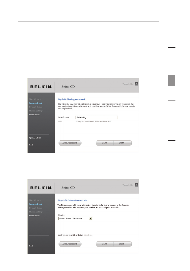
1.3 Naming your Wireless Network
The Setup Assistant will display the default wireless network name
or Service Set Identifier (SSID). This is the name of your wireless
network to which your computers or devices with wireless network
adapters will connect. You can either use the default or change it to
something unique. Write down this name for future reference. Click
“Next” to continue.
1.4 Requesting Internet Account Info (if needed)
If your Internet account requires a login and password, you will be
prompted with a screen similar to the illustration below. Select your
country or ISP from the drop-down boxes.
1
2
3
sec tion
4
5
6
7
8
9
10
1918
Page 22
Connecting and Configuring your Router
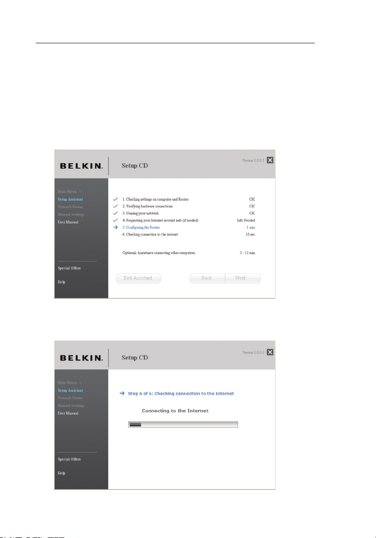
1.5 Configuring the Router
The Setup Assistant will now configure your Router by sending data to the
Router and restarting it. Wait for the on-screen instructions.
Note: Do not disconnect any cable or power off the Router while the
Router is rebooting. Doing so will render your Router inoperable.
1.6 Checking Internet Connection
We are almost done. The Setup Assistant will now check your
connection to the Internet.
20
Page 23

2120
Connecting and Configuring your Router
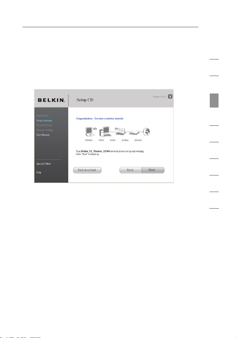
Congratulations
You have finished installing your new Belkin Router. You will see
the Congratulations screen when your Router can connect to the
Internet. You can begin surfing by opening your browser and going
to any website.
You can use the Setup Assistant to set up your other wired and wireless
computers to connect to the Internet by clicking “Next”. If you decide to
add computers to your Router later, select “Exit the Assistant” and then
click “Next”.
1
2
3
sec tion
4
5
6
7
8
9
10
2120
Page 24

Connecting and Configuring your Router
Troubleshooting
If the Setup Assistant is not able to connect to the Internet, you will see
the following screen. Follow the on-screen instructions to go through the
troubleshooting steps.
1.7 Optional: Assistance Connecting Other Computers
This optional step will help you to connect additional wired and wireless
computers to your network. Follow the on-screen instructions.
22
Page 25
2322
Connecting and Configuring your Router
Congratulations
Once you have verified that your other wired and wireless
computers are properly connected, your network is set up and
working. You can now surf the Internet. Click “Next” to take you
back to the main menu.
1
2
3
sec tion
4
5
6
7
8
9
10
2322
Page 26

Alternate Setup Method
The Web-Base d A dvanced User Int erf ace is a web-based too l that you can
use to set u p t he Router if you do n’t want to use the Ea sy Install Wizard.
You can also us e it to manage a dva nced functions of t he Router. From the
Web-Based Ad van ced User Interfa ce, you can perform th e f ollowing tasks:
• View the Ro uter’s cu rre nt settin gs and status
• Config ure the Router to connect to your ISP with the sett ing s that they
provided you
• Change the current n etw ork setti ngs such as th e Interna l IP address, the
IP ad dress poo l, DHCP settings, and m ore
• Set the Rou ter’s fir ewa ll to work with spec ifi c applica tio ns
(port forwarding)
• Set up s ecu rity feat ure s such as c lient res tri ctions, M AC address
filtering, WEP, a nd WPA
• Enable the DMZ featu re for a si ngl e compute r on your netw ork
• Change the Router’s int ernal pas swo rd
• Enable /Di sable UPn P (Universal Plug-and-Pl ay)
• Reset the R outer
• Back up you r configu rat ion setti ngs
• Reset the R outer’s d efa ult setti ngs
• Update the Router’s fir mware
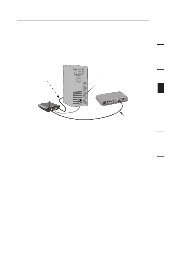
Step 1 Connect your Router
Turn off the power to you r modem by unp lug ging t he power supply
1.1
from the modem .
1.2 L oca te the network cable th at is connected between yo ur mod em
and y our compu ter and unplug it from your computer, leaving the
other end conn ect ed to your modem.
1.3 Plug th e loose end of the cable you just unplugged into th e port on
the b ack of the Router la bel ed “Modem ”.
1.4 Connect a new network cable (no t included) from the ba ck of the
computer to on e of the wi red computer s ports labeled “1–4”.
Note: It does not matter whi ch number ed port you ch oose.
24
Page 27
2524
Alternate Setup Method
1.5 Turn you r cable or DSL modem on b y reconnecti ng the power
supply to the modem.
Mac or PC computer that was originally
connected to the cable or DSL modem
Network cable
To power adapter
Note: Your Router m ay have ports in differ ent location s than
depicted in th e illustr ati on above.
1.6 Before p lug ging t he power cord int o the Router, plug t he cord
into the wall, then plug the cord into the Route r’s power jack.
1.7 Verify t hat your modem is conne cte d to the Ro ute r by checking
the l ights on the front o f the Router. The green light labeled
“Modem” should be ON if y our modem is c onn ected cor rectly to
the R outer. If it is not, recheck your con nections.
(to computer)
Existing networking cable
(came with modem)
1
2
3
4
sec tion
5
6
7
8
9
10
1.8 Verify that your computer is c onnected pro perly to the Router by
checking the l igh ts lab ele d “1-4”. The l ight that correspo nds to
the n umbered p ort conne cte d to your c omp uter shou ld be ON if
your computer is connec ted properly . If it is not, recheck
your connections.
2524
Page 28
Alternate Setup Method
Step 2 Set up your Computer’s Network Settings to Work
with a DHCP Server
See the sect ion in this User Ma nua l called “Manually Con figuring Network
Settings” fo r d irections.
Step 3 Configure the Router Using the Web-Based
Advanced User Interface
Using your I nte rnet browser, yo u c an access the Route r’s Web-Based
Advanced Use r I nterface. In you r b rowser, type “192.1 68. 2.1” (you do not
need to type in anything else s uch as “http://” or “w ww” ). Then press the
“Enter” key.
PLEASE NOTE: If you have diffic ult y accessing the Rou ter ’s
Web-Based Ad van ced User Interfa ce, go to the section ent itled “Manually
Configuring Net work Settings”.
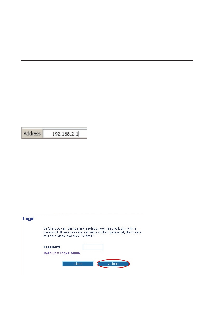
Logging into the Router
You will see th e Router’s home pag e in your browser w ind ow. The home
page is visi ble to any user who wa nts to see it. To m ake any changes to
the Router’s se ttings, you have to log in. Clicking t he “Login” button or
clicking on any one of the link s o n the home page wil l take you to th e l ogin
screen. The Rou ter ships with n o p assword entered. In th e login screen,
leave the pa ssw ord blank and cl ick the “Submit” butto n t o log in.
26
Page 29

2726
Alternate Setup Method
Logging out of the Router
One computer at a time can log int o the Router for th e p urposes
of making ch ang es to the settin gs of the Router. Once a user has
logged in to ma ke changes, ther e a re two ways that th e c omputer
can be logge d o ut. Clicking the “L ogout” button will log the computer
out. The sec ond method is autom ati c. The login will t ime out after a
specified pe rio d of time. The d efa ult login time-out is 10 minutes. This
can be chang ed from 1 to 99 min ute s. For more informa tio n, see the
section in t his manual entitled “C hanging the Login T ime -Out Setting”.
Using the Web-Based Advanced User Interface
The home pag e i s the first page yo u will see when you ac cess the
Web-Based Ad van ced User Interfa ce (UI). The home page sh ows you
a quick view of the Router’s st atu s and settings. All ad vanced setup
pages can be re ached from this pag e.
(10) (2) (5) (4) (3)
(1)
(7)
(8)
1
2
3
4
sec tion
5
6
7
8
9
(6)
10
(9)
1. Quick-Navigation Links
You c an go directly to an y of the Route r’s UI pages b y clickin g
directly on th ese links . The links ar e divided into logical
categories and gr ouped by tabs to mak e finding a pa rticular
setting easier to find. Clicking on t he purple header of eac h tab
will show you a short des cri ption of the t ab’s f unc tion.
2. Home Button
The “ Home” but ton is available in eve ry page of the UI. Pressing
this button wi ll take you ba ck to the h ome page.
2726
Page 30

Alternate Setup Method
3. Internet Status Indicator
This indicator is visib le in all page s of the UI , indicating the
connection status of th e Router. When th e indicat or says
“connection OK” i n GREE N, the Router is connected to the
Internet. When th e Rout er is not conn ect ed to the I nternet, the
indicator will re ad “no connection” in R ED. The indicator is
automaticall y updated when you make changes to th e setting s of
the R outer.
4. Login/Logout Button
This button en abl es you to l og in and o ut of the R out er with the
press of one button. When yo u are logged i nto th e Router, this
button will ch ang e to read “ Logout”. Log ging into the Router wi ll
take you to a se parate lo gin page where yo u will need to enter a
password. When yo u are logged into th e Router, you can make
changes to the settings . When you are finished making changes,
you c an log out of the Router by clicki ng the “Logout” button.
For m ore infor mat ion ab out logging into the Route r, see the
section called “L ogging in to the Router”.
5. Help Button
The “ Help” but ton gives you access to the Router’s help page s.
Help is also available on ma ny pages by cl icking “m ore info”
next to certai n section s of each page .
28
Page 31

2928
Alternate Setup Method
6. LAN Settings
Shows you the settings of th e Local Area N etwork (L AN) side of
the R outer. Ch ang es can be m ade to the set tings by clicking on
any o ne of the l inks (IP Address, Subnet M ask, D HCP Server) or
by cl icking th e “LAN” “Quick Navigation” link on the left si de of
the s creen.
7. Features
Shows the stat us of the R out er’s NAT, firewall, and wireless
features. Changes can b e made to the settings by cl icking on
any o ne of the l inks or by cli cking the “Quick Navigation” links
on th e left side of the screen.
8. Internet Settings
Shows the sett ing s of the In ternet/WAN s ide of the Router th at
connects to th e Interne t. Changes to any of these s ettings c an
be ma de by clicking on th e links or by clicking on th e
“Internet/WA N” “Quick Navigation” link on the left s ide of
the s creen.
9. Version Info
Shows the firm war e vers ion , boot-co de version, hardware
version, and s eri al num ber of the Rou ter .
10. Page Name
The p age you are on can be ide ntified b y this name. T his User
Manual will so met imes r efe r to pages by name. For i nstance
“LAN > LAN Settings” refers to the “LAN Se ttings” p age.
1
2
3
4
sec tion
5
6
7
8
9
10
2928
Page 32

Alternate Setup Method
Step 4 Configure your Router for Connection to your Internet
Service Provider (ISP)
The “Interne t/W AN” tab is where yo u will set up your Rou ter to connect to
your Interne t S ervice Provider (IS P). The Router is c apa ble of connecting
to virtually an y ISP’s system p rov ided you have corre ctl y configured the
Router’s set tin gs for your ISP’ s c onnection type. You r I SP connection
settings are pr ovided to you by yo ur ISP. To configur e t he Router with the
settings tha t y our ISP gave you , c lick “Connection Ty pe” (A) on th e left
side of the scr een. Select the con nection type you us e. If your ISP gave
you DNS sett ing s, clicking “DNS ” (B) allows you to enter DNS ad dre ss
entries for ISP s that require s pec ific settings. Clic kin g “MAC address” (C)
will let you cl one your compute r’s MAC address or typ e i n a specific WAN
MAC address, if required by you r I SP. When you have f ini shed making
settings, th e “ Internet Status” in dicator will read “ con nection OK” if your
Router is se t u p properly.
(A)
(B)
(C)
30
Page 33

3130
Alternate Setup Method
Setting your Connection Type
From the “Connection Type” page, you can select the type of connection
you use. Select the type of connection you use by clicking the button (1)
next to your connection type and then clicking “Next” (2).
(1)
(2)
1
2
3
4
sec tion
5
6
7
8
9
10
3130
Page 34

Alternate Setup Method
Setting your Internet Service Provider (ISP) Connection Type to Dynamic IP
A dynamic connection type is the most common connection type used with
cable modems. Setting the connection type to “dynamic” in many cases is
enough to complete the connection to your ISP. Some dynamic connection
types may require a host name. You can enter your host name in the space
provided if you were assigned one. Your host name is assigned by your ISP.
Some dynamic connections may require that you clone the MAC address
of the PC that was originally connected to the modem.
Change WAN MAC Address
If your ISP req uires a specific MA C address to connec t t o the service,
you can ente r a specific MAC ad dre ss or clone the cur ren t computer’s
MAC address thr ough this link.
32
Page 35
3332
Alternate Setup Method
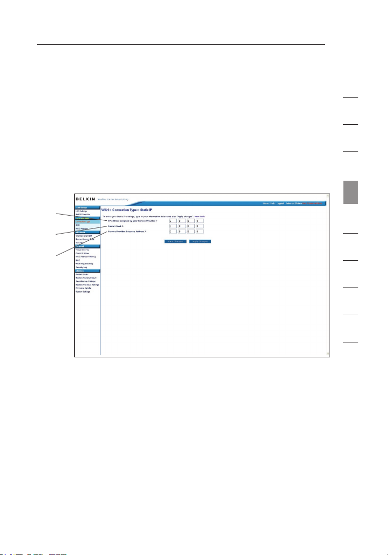
Setting your Internet Service Provider (ISP) Connection
Type to Static IP
A static IP address connection type is less common than other connection
types. If your ISP uses static IP addressing, you will need your IP address,
subnet mask, and ISP gateway address. This information is available from
your ISP or on the paperwork that your ISP left with you. Type in your
information, then click “Apply Changes”
the “Internet Status” indicator will read “connection OK” if your Router is
set up properly.
(1)
(2)
(3)
1. IP Address
Provided by yo ur ISP. Enter your IP address here.
(5). After you apply the changes,
1
2
3
4
sec tion
5
6
7
8
9
10
2. Subnet Mask
Provided by yo ur ISP. Enter your subn et mask here.
3. ISP Gateway Address
Provided by yo ur ISP. Enter the ISP gateway address here.
3332
Page 36

Alternate Setup Method
Setting your ISP Connection Type to PPPoE
Most DSL pro vid ers use PPPoE as th e connection type. If you use a
DSL modem to co nnect to the Int ern et, your ISP may us e P PPoE to
log you into th e service. If yo u h ave an Internet con nec tion in your
home or smal l o ffice that doesn ’t require a modem, yo u m ay also
use PPPoE.
(1)
(2)
(3)
(4)
(5)
Your connection type is PPPoE if:
1.
Your ISP gave you a user name and passw ord , whic h is required
to co nnect to the Internet;
2. Your ISP g ave you software such a s WinPOET or E nternet300
that you use to connect t o the Internet; o r
3. You hav e to double-click on a desktop icon other t han your
browser to get on the Int ern et.
34
Page 37

3534
Alternate Setup Method
1. User Name
This space is provided to ty pe in your use r name that was
assigned by yo ur ISP.
2. Password
Type in your password and re -type it into the “R ety pe
Password” box to confir m it.
3. Service Name
A service n ame is rarely required by an ISP. If you ar e not sure if
your ISP requi res a service name, lea ve this blank.
4. MTU
The M TU settin g should never be chang ed unless your ISP give s
you a specific MTU setting. Making ch ang es to the M TU settin g
can c ause prob lem s with your Internet co nnection inc luding
disconnectio n from the Int ernet, sl ow Internet access, and
problems with Int ernet app lications wo rking pro per ly.
5. Disconnect after x minutes...
This feature i s used to a uto matically di sconnect the Route r
from your ISP when there is no activity fo r a specified period
of ti me. For instance, placing a chec k mark next to this option
and e ntering “ 5” into the mi nute fiel d will cause t he Router to
disconnect from t he Int ern et after five minutes o f no Internet
activity. This op tion s hou ld be used if you pay for your Internet
service by the minute.
1
2
3
4
sec tion
5
6
7
8
9
10
3534
Page 38

Alternate Setup Method
Setting your Internet Service Provider (ISP) Connection Type to
Point-to-Point Tunneling Protocol (PPTP)
[European Co unt ries Only]. Some IS Ps require a connec tio n using PPTP
protocol, a typ e of connection mos t common in Europea n c ountries. This
sets up a di rec t connection to the ISP’s system. Type in the information
provided by you r ISP in the spa ce provided. When you hav e finished,
click “Apply Ch anges” (9). Afte r y ou apply the change s, the “Internet
Status” indi cat or will read “co nne ction OK” if your R out er is set up
properly.
(1)
(2)
(3)
(4)
(5)
(6)
(7)
(8)
1. PPTP Account
Provided by yo ur ISP. Enter your PPTP User ID he re.
2. PPTP Password
Type in your password and re type it into t he “Re typ e Passwor d”
box t o confirm it.
3. Host Name
Provided by yo ur ISP. Enter your host name here.
4. Service IP Address
Provided by yo ur ISP. Enter your PPTP gateway/ser vic e IP
address here.
36
(9)
Page 39

3736
Alternate Setup Method
5. My IP Address
Provided by yo ur ISP. Enter the IP address here.
6. My Subnet Mask
Provided by yo ur ISP. Enter the IP address here.
7. Connection ID
Provided by yo ur ISP. Enter the conne cti on ID here.
8. Disconnect after x minutes...
This feature i s used to a uto matically di sconnect the Route r
from your ISP when there is no activity fo r a specified period
of ti me. For instance, placing a chec k mark next to this option
and e ntering “ 5” into the mi nute fiel d will cause t he Router to
disconnect from t he Int ern et after five minutes o f no Internet
activity. This op tion s hou ld be used if you pay for your Internet
service by the minute.
1
2
3
4
sec tion
5
6
7
8
9
10
3736
Page 40

Alternate Setup Method
Setting your Connection Type if you are a Telstra® BigPond User
[Australia O nly ]. Your user nam e a nd password are pro vid ed to you by
Telstra BigP ond . Enter this inf orm ation below. Choosi ng your state from
the drop-dow n m enu
address. If you r login server a ddr ess is different th an the one provided
here, you ma y m anually enter th e l ogin server IP addr ess by placing a
check in the bo x next to “User dec ide login server ma nua lly”
type in the add ress next to “Lo gin Server” (5). When you h ave entered
all of your inf ormation, click “Ap ply Changes” (7). After you a ppl y the
changes, the “I nternet Status” ind icator will read “c onn ection OK” if
your Router is set up properly.
(1)
(2)
(6) will automatically fi ll in your login se rve r IP
(4) and
(3)
(4)
(5)
(7)
1. Select your State
Select your st ate from the d rop-down men u (6). The “Logi n Server”
box w ill autom ati cally be filled in w ith an IP a ddr ess. If for so me
reason this ad dre ss doe s not match th e address that Telstra has
given, you can manually enter the log in server address. See “Us er
decide login s erv er man ual ly”
(4).
2. User Name
Provided by yo ur ISP. Type i n your user na me her e.
3. Password
Type in your password and re type it into t he “Re typ e Passwor d”
box t o confirm it.
38
(6)
Page 41

3938
Alternate Setup Method
4. User Decide Login Server Manually
If yo ur login server IP a ddr ess is not ava ilable in the “Select Y our
State” drop-down menu
server IP addr ess by placing a check in th e box next to “User
decide login s erv er man ual ly” and typing in the address next to
“Login Server”
Setting Custom Domain Name Server (DNS) Settings
A “Domain Na me Server” is a ser ver located on the Int ern et that
translates U niv ersal Resource L oca tors (URLs) like “w ww. belkin.
com” into IP ad dresses. Many In ter net Service Provide rs (ISPs) do not
require you to enter this infor mat ion into the Router . T he “Automatic
from ISP” bo x
specific DNS ad dress. If you ar e u sing a static IP co nne ction type,
then you may ne ed to enter a sp eci fic DNS address and se condary
DNS address for your connection to work properly. If you r connection
type is dyna mic or PPPoE, it is li kely that you do no t h ave to enter a
DNS address. Le ave the “Automat ic from ISP” box check ed. To enter
the DNS addr ess settings, unche ck the “Automatic from IS P” box and
enter your D NS entries in the s pac es provided. Click “Ap ply Changes”
(2) to save the settings.
(1)
(5).
(1) should be checked if your ISP did not give you a
(6), you may m anu ally e nte r the login
1
2
3
4
sec tion
5
6
7
8
9
10
(2)
3938
Page 42

Alternate Setup Method
Configuring your WAN Media Access Controller (MAC) Address
All network com ponents includin g c ards, adapters, and ro uters, have
a unique “se ria l number” called a MAC address. Your I nte rnet Service
Provider may re cord the MAC add res s of your computer’ s a dapter
and only let th at particular co mpu ter connect to the Int ernet service.
When you ins tal l the Router, it s o wn MAC address will be “seen” by the
ISP and may cau se the connectio n n ot to work. Belkin has provided
the ability to clone (copy) the MA C address of the co mpu ter into the
Router. This MA C address, in tu rn, will be seen by th e I SP’s system as
the original MA C address and wi ll allow the connectio n t o work. If you
are not sure wh ether your ISP n eed s to see the origin al MAC address,
simply clone th e MAC address of th e computer that was or iginally
connected to th e modem. Cloning th e address will not cau se any
problems wit h y our network.
40
Page 43

4140
Alternate Setup Method
Cloning your MAC Address
To clone you r M AC address, make su re that you are usi ng the
computer tha t w as ORIGINALLY CO NNE CTED to your modem bef ore
the Router w as installed. Click th e “Clone” button
Changes” (3). Y our MAC address is now cloned to the R out er.
Entering a Specific MAC Address
In certain c irc umstances you ma y n eed a specific WAN MAC address.
You can manu all y enter one in t he “MAC Address” page. Ty pe in a
MAC address in the spaces provi ded (2) and c lic k “Apply
Changes” (3) to save the chan ges . The Router’s WAN MAC address
will now be cha nged to the MAC add ress you specified.
(1). Click “Apply
(2)
(1)
(3)
1
2
3
4
sec tion
5
6
7
8
9
10
4140
Page 44

Using the Web-Based Advanced User Interface
Using your I nte rnet browser, yo u c an access the Route r’s Web-Based
Advanced Use r I nterface. In you r b rowser, type “192.1 68. 2.1” (do
not type in any thing else such as “http://” or “www”) th en press the
“Enter” key.
You will see th e Router’s home pag e in your browser w ind ow.
Viewing the LAN Settings
Clicking on the header of the “ LAN Setup” tab (1) will take y ou to its
header page. A quick descriptio n o f the functions can be found here.
To view the set tings or make ch ang es to any of the LA N s ettings, click
on “LAN Sett ing s” (2) or to view the list of co nnected computer s, click
on “DHCP Cli ent List” (3).
(1)
(2)
(3)
42
Page 45
4342
Using the Web-Based Advanced User Interface
Changing LAN Settings
All settings fo r the internal L AN setup of the Router ca n be viewed and
changed here .
1. IP Address
The “ IP addres s” is the i nte rnal IP address of t he Router. The
default IP add res s is “192.168.2.1” . To access th e Web-Bas ed
Advanced User Int erface, t ype this IP ad dress int o the address
bar o f your browser. This ad dress can be c hanged if needed.
To ch ange the IP address, ty pe in the n ew IP address and click
“Apply Changes”. The IP address you c hoo se should be a
non-routable IP.
Examples of a non-routa ble IP are:
192.168.x.x (where x is anything between 0 and 255), and
10.x.x.x (where x is anything between 0 and 255).
2. Subnet Mask
There is no need to chang e the subnet m ask . This is a unique,
advanced feature of you r Belkin Router. It is possible to ch ang e
the s ubnet mas k if necessary; however, d o
the s ubnet mas k unless you h ave a specific reason t o do so. Th e
default setting i s “255 .25 5.255.0”.
(1)
(2)
NOT ma ke change s to
1
2
3
4
5
sec tion
6
7
8
9
10
(3)
(4)
(5)
(6)
4342
Page 46

Using the Web-Based Advanced User Interface
3. DHCP Server
The D HCP serve r functio n makes setting u p a network very eas y
by as signing I P address es to each com put er on the n etwork
automaticall y. The default setting is “On”. The D HCP serve r
can b e turned OFF if nece ssa ry; howev er, in order t o do so you
must manually set a static I P address for each c omp uter on your
network. To tu rn off the DHC P server, select “Off” and click
“Apply Changes”.
4. IP Pool
The range of IP addresses set aside for dynamic assignment to the
com pute rs on your network. The defa ult is 2–100 (99 computers). If
you want to change this number, you can do s o by entering a new
sta rtin g and ending IP address and clicking on “Apply Changes”.
The DHCP server can assign 100 IP addresses automatically. This
mea ns that you cannot specify a n IP address pool larger tha n 100
com pute rs. For example, starting at 50 means you have to en d at
150 or lower so as not to exceed the 100 -cli ent limit. The starting IP
add ress must be lower in number than the ending IP address.
5. Lease Time
The l ength of time the DH CP server will re serve the IP address fo r
each computer. We recom men d that you lea ve the lease time se t to
“Forever”. The de fault set ting is “Forever”, meaning that any time
a com puter is assigned an IP address by th e DHCP server, the I P
address will n ot change for that part icu lar compu ter . Sett ing lease
times for shor ter inter val s such as o ne day or o ne hour frees IP
addresses after t he spe cif ied perio d of time. Thi s also means t hat a
particular computer’s IP a ddress ma y change over tim e. If you h ave
set a ny of the o ther adva nce d feature s of the Ro ute r such as D MZ
or cl ient IP filters, these are depen den t on the IP address. For this
reason, you wi ll not want th e IP address t o chan ge.
6. ILocal Domain Name
The default setting is “Belkin”. You can set a local domain name
(network name) for your network. There is no need to change this
setting unless you have a specific advanced need to do so. You can
name the network anything you want such as “MY NETWORK”.
44
Page 47
4544
Using the Web-Based Advanced User Interface
Viewing the DHCP Client List Page
You can view a list of the comp ute rs (known as client s), which are
connected to yo ur network. You are able to view the I P a ddress (1) of
the computer , t he host name (2) (i f t he computer has bee n assigned
one), and th e M AC address (3) of the compute r’s network interfa ce
card (NIC). Pre ssing the “Refre sh” (4) butto n w ill update the l ist . If
there have b een any changes, th e l ist will be updated .
(1) (2) (3)
(4)
1
2
3
4
5
sec tion
6
7
8
9
10
4544
Page 48

Using the Web-Based Advanced User Interface
Configuring the Wireless Network Settings
Clicking on the header of the “ Wir eless” tab will tak e y ou to the
“Wireless” h ead er page. Under t he “Wireless” tab, the re are links that
allow you to ma ke changes to th e w ireless network set tin gs.
Changing the Wireless Network Name (SSID)
To identify you r wireless netwo rk, a name called the SSI D (Service Set
Identifier) is used. The defaul t S SID of the Router i s “ belkin54g”. You
can change t his to anything you wa nt to or you can le ave it unchanged.
If there are other wireless networks operating in your area, yo u will want
to make sure th at your SSID is uni que (does not match th at of another
wireless net wor k in the area). To change the SSID, ty pe in the SSID
that you wan t t o use in the “SS ID” field (1) and clic k “ Apply Changes”
(2). The cha nge is immediate. I f y ou make a change to th e SSID, your
wireless-equ ipp ed computers may al so need to be recon fig ured to
connect to y our new network nam e. Refer to the docume nta tion of your
wireless net wor k adapter for in for mation on making th is change.
46
Page 49

4746
Using the Web-Based Advanced User Interface
1
2
Using the Wireless Mode Switch
Your Router can operate in thre e d ifferent wireless m ode s:
“g and b”, “ g o nly”, and “b onl y”. The different mode s a re
explained on th e next page.
(1)
3
4
5
(2)
sec tion
6
7
8
9
10
4746
Page 50

Using the Web-Based Advanced User Interface
g and b Mode
In this mode , t he Router is com pat ible with 802.11b a nd 802.11g wireless
clients simu lta neously. This is th e factory default m ode and ensures
successful o per ation with all W i-F i-compatible device s. If you have a mix
of 802.11b a nd 802.11g clients in your network, we re com mend setting
the Router t o g and b mode. Thi s s etting should only be changed if you
have a speci fic reason to do so .
g only Mode
g only mode wor ks with 802.11g cli ents only. This mod e i s recommended
only if you wan t to prevent 802 .11 b clients from acce ssi ng your network.
To switch mo des , select the des ire d mode from the “Wi rel ess Mode”
drop-down bo x. Then, click “App ly Changes”.
b only Mode
We recommend yo u DO NOT use thi s m ode unless you have a very
specific rea son to do so. This mod e exists only to so lve unique problems
that may occ ur with some 802.11 b c lient adapters and is NOT necessary
for interope rab ility of 802.11g an d 802.11b standards .
When to use b only Mode
In some case s, older 802.11b cl ien ts may not be compa tib le with 802.11g
wireless. Th ese adapters tend t o b e of inferior desig n a nd may use older
drivers or t ech nology. Switchin g t o this mode can sol ve problems that
sometimes oc cur with these clie nts . If you suspect th at you are using a
client adapt er that falls into thi s category of adapt ers , first check with
the adapter ven dor to see if th ere is a driver update . I f there is no drive r
update avail abl e, switching to b o nly mode may fix yo ur problem. Please
note that sw itc hing to b only m ode will decrease 802. 11g performance.
QoS (Quality of Service) Configuration
QoS prioriti zes important data on your network such a s m ultimedia
content and Voi ce over IP (VoIP ) s o it will not be in ter fered with by
other data b ein g sent over the net work. Based on 802. 11e , you can turn
this feature on or off by selec tin g it from the drop- dow n menu (3) and
choosing the ac knowledgement mo de you want to use. If yo u plan to
stream multi med ia content or us e V oIP on your network , w e recommend
that you ena ble the QoS feature .
Changing the Wireless Channel
There are a num ber of operating ch annels you can choo se from. In the
United State s, there are 11 cha nne ls. In Australia, t he United Kingdom,
and most of Eur ope, there are 1 3 c hannels. In a small nu mber of
other countr ies , there are othe r c hannel requirements . Y our Router is
configured t o o perate on the pr ope r channels for the cou ntry you reside
in. The defa ult channel is 11 ( unl ess you are in a co unt ry that does not
allow channe l 1 1). The channel can be changed if need ed. If there are
other wirele ss networks operati ng in your area, your net work should
be set to op era te on a channel tha t is different than th e other wireless
48
Page 51

4948
Using the Web-Based Advanced User Interface
networks. Fo r b est performance, us e a channel that is at least five
channels awa y f rom the other wi rel ess network. For in sta nce, if another
network is o per ating on channel 11 , then set your net wor k to channel 6
or bel ow. To change the channel, select the channel from the drop-down
list. Click “Ap ply Changes”. Th e c hange is immediate
Using the Broadcast SSID Feature
Note: This advanc ed feat ure should be empl oyed by adv anced u sers only.
For security , y ou can choose no t t o broadcast your ne two rk’s SSID.
Doing so wil l k eep your network na me hidden from comp ute rs that
are scanning fo r the presence o f w ireless networks. T o t urn off the
broadcast of th e SSID, remove t he check mark from the bo x next to
“Broadcast S SID ”, and then clic k “ Apply Changes”. The ch ange is
immediate. E ach computer now ne eds to be set to conne ct to your
specific SSI D; an SSID of “ANY” wi ll no longer be acc ept ed. Refer to
the document ati on of your wirel ess network adapter fo r i nformation on
making this cha nge.
Protected Mode Switch
As part of t he 802.11g specific ati on, Protected mode ens ures proper
operation of 80 2.11g clients an d a ccess points when t her e is heavy
802.11b traf fic in the operatin g e nvironment. When Pr ote cted mode is
ON, 802.11g sca ns for other wir ele ss network traffic bef ore it transmits
data. Theref ore , using this mod e i n environments with HE AVY 802.11b
traffic or i nte rference achieve s b est performance res ult s. If you are in an
environment wit h very little—or no —other wireless net wor k traffic, your
best perform anc e will be achiev ed with Protected mode OF F.
.
1
2
3
4
5
sec tion
6
7
8
9
10
4948
Page 52

Using the Web-Based Advanced User Interface
Securing your Wi-Fi® Network
Here are a few d ifferent way s you can m axi mize t he security of yo ur
wireless network and pr ote ct your data f rom pryin g eyes and ear s. This
section is int end ed for the home, hom e office, and small off ice user.
At th e time of t his User Manual’s publication, there are fou r encryption
methods available.
Name 64-Bit Wired
Acrony m 64-bit WE P 128-bi t W EP WPA -TKIP/A ES
Securi ty Good Be tter Best Best
Featur es Static ke ys Stati c keys Dynami c k ey
Equivalent
Privacy
Encryp tion
keys base d
on RC4
algori thm
(typic ally
40-bit ke ys)
128-Bit Wired
Equivalent
Privacy
More secu re
than 64-b it
WEP using a
key lengt h of
104 bits plus
24 additi onal
bits of systemgenera ted dat a
Wi-Fi Protected
Access-TKIP
(or just WPA)
encryp tion
and mutua l
authen tica tion
TKIP (Tem pora l
Key Integ rity
Protoc ol)
added so
that keys are
rotate d a nd
encryp tion is
streng then ed
Wi-Fi Protected
Access 2
WPA2-A ES
(or just WPA2)
Dynami c k ey
encryp tion
and mutua l
authen tica tion
AES (A dvanced
Encryp tion
Standa rd)
does not
cause any
thr oughput loss
Wired Equivalent Privacy (WEP)
WEP i s a common protocol tha t adds security to a ll Wi-Fi-com pli ant
wireless products. WEP was designed to g ive wirel ess netwo rks the
equivalent level of pri vac y protect ion as a compa rab le wir ed network.
64-Bit WEP
64-bit WEP was first introduced with 64- bit encry pti on, wh ich includes
a key length of 40 bits plus 2 4 additio nal bits of sy stem-generated data
(64 b its total ). Some hardware manufacturers refer t o 64-b it as 40-bit
encryption. Shortly after the techn olo gy was introduced, researchers
found that 64- bit encry pti on was too eas y to decode.
50
Page 53

5150
Using the Web-Based Advanced User Interface
128-Bit WEP
As a result of 6 4-bit WEP ’s potential security weaknesses, a mo re
secure method of 128-bi t encryption was developed. 1 28-bit
encryption includes a k ey length of 1 04 bits plus 2 4 additio nal bits of
system-gener ate d data (128 bits tot al) . Some hardware manufacturers
refer to 128-b it as 104-bit encryption.
Most of the new wireless equ ipment in the market to day suppo rts
both 64-bit an d 128-bit WEP encryption, but you might have o lde r
equipment that only sup ports 64- bit WEP. All Belkin wireless products
will support b oth 64-bi t and 128-bit WEP .
Encryption Keys
After selecting either the 64-bit or 128-bit WEP encryption mode, it is
critical that you generate an encryption key. If the encryption key is
not consistent throughout the entire wireless network, your wireless
networking devices will be unable to communicate with one another
on your network and you will not be able to successfully communicate
within your network.
You c an enter your key by typing in the hex key ma nua lly, or you ca n
type in a passphrase in t he “Passphra se” field and click “Ge ner ate”
to cr eate a key. A hex (hexadecimal) key i s a combination of n umb ers
and l etters fr om A–F and 0–9 . For 64-bit W EP, yo u need to ente r 10
hex k eys. For 128-bit WEP, y ou need to ent er 26 hex k eys.
For i nstance:
AF 0F 4B C3 D4 = 64-bit WEP key
C3 03 0F AF 0F 4B B2 C3 D4 4B C3 D4 E7 = 128-bit WEP key
The W EP passph ras e is NOT th e same as a WEP key. Y our Router
uses this pass phr ase to generate your WE P keys, but different
hardware manufacturer s might have d iff erent met hod s on generating
the k eys. If you have mul tip le vendor s’ equipment in your ne two rk,
the e asiest th ing to do i s to use the hex WEP key from your Rout er or
access point a nd enter it ma nually in to the hex WEP key table in your
Router’s configuratio n screen.
1
2
3
4
5
sec tion
6
7
8
9
10
5150
Page 54

Using the Web-Based Advanced User Interface
Wi-Fi Protected Access™ (WPA™)
WPA is a new Wi-Fi standard that was designed to improve upon the security
features of WEP. To use WPA security, the drivers and software of your
wireless equipment must be upgraded to support WPA. These updates will
be found on the wireless vendor’s website. There are three types of WPA
security: WPA-PSK (no server), WPA (with radius server), and WPA2.
WPA-PSK (no server) uses what is known as a pre-shared key as the
network key. A network key is basically a password that is between eight
and 63 characters long. It can be a combination of letters, numbers, or
characters. Each client uses the same network key to access the network.
Typically, this is the mode that will be used in a home environment.
WPA (with radius server) is a system where a radius server distributes
the network key to the clients automatically. This is typically found in a
business environment.
™
WPA2
requires Advanced Encryption Standard (AES) for encryption
of data, which offers much greater security than WPA. WPA uses both
Temporal Key Integrity Protocol (TKIP) and (AES) for encryption.
For a list of Belkin wireless products that support WPA, please visit our
website at www.belkin.com/networking.
52
Page 55

5352
Using the Web-Based Advanced User Interface
Sharing the Same Network Keys
Most Wi-Fi products ship with security turned off. So once you have your
network working, you need to activate WEP or WPA and make sure your
wireless networking devices are sharing the same network key.
The W ireless G Desktop Card cannot ac ces s the network because i t
is using a different network ke y than the network key that is configured
on th e Wireles s G Router.
1
2
3
4
5
sec tion
6
7
8
9
10
5352
Page 56

Using the Web-Based Advanced User Interface
Using a Hexadecimal Key
A hex adecimal key is a co mbi nation of numbers and l etters fr om A–F and
0–9. 64-bit ke ys are five tw o-digit n umb ers. 128- bit keys are 1 3
two-digit numbers.
For i nstance:
AF 0F 4B C3 D4 = 64-bit key
C3 03 0F AF 0F 4B B2 C3 D4 4B C3 D4 E7 = 128-bit key
In th e boxes below, make up your key by writing in tw o charact ers
between A–F an d 0–9 in ea ch box. You wi ll use this ke y to program t he
encryption settings on you r Router and y our wirel ess compu ter s.
Note to Mac users: Or igi nal Ap ple
64-bit encryption only. Ap ple AirPo rt 2 products can suppo rt 64-bit or
128-bit encryption. Please check yo ur product to see which version you
are u sing. If you cannot con figure yo ur network with 128-bit en cryption,
try 6 4-bit enc ryp tion.
®
A irP ort® p rod ucts supp ort
54
Page 57
5554
Using the Web-Based Advanced User Interface
WEP Setup
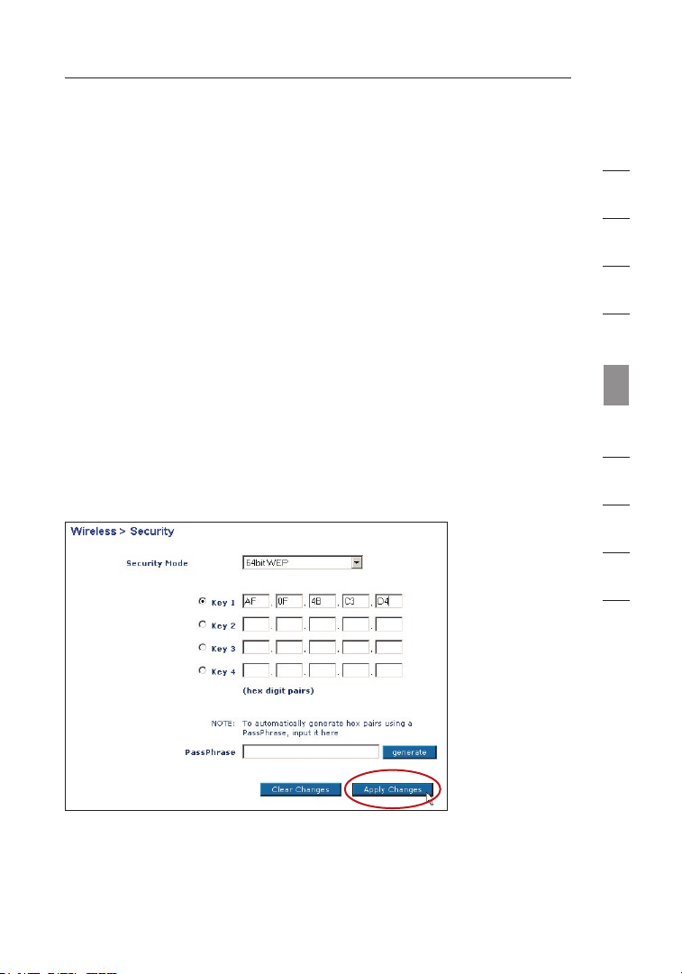
64-Bit WEP Encryption
1.
Select “64-bit WE P” fro m the “Security” menu’s
“Security Mode”.
2. After s electing your WEP encryption mode, you ca n enter your
key b y typing in the hex key m anually, or you can put a check
mark in “Passp hra se”, t hen type in yo ur passphras e. Click
“Generate” to gen erate fou r differe nt hex keys.
A hex (hexadecimal) key is a combination of numbers and le tter s
fro m A–F and 0–9. For 64-bit WEP, you need t o enter 10
hex keys.
For instance: AF 0F 4B C3 D4 = 64-bit WEP key
3.
Click “Apply C han ges” t o save the set tin g.
1
2
3
4
5
sec tion
6
7
8
9
10
WARNING: If y ou are configuring the Wir eless G Router or acces s
point from a computer with a wireless client, you w ill need to en sure
that security is turned ON f or this wireless client. If this is n ot done,
your client wi ll lose its wi reless co nne ction.
5554
Page 58

Using the Web-Based Advanced User Interface
128-Bit WEP Encryption
Note to Mac users:
Apple AirPort. To confi gur e encrypt ion for your M ac comput er, set the
encryption using the ma nua l method described in t he next section.
1. Select “128-bit WEP” from the “Sec urit y” menu’s “Security Mode”.
2. After s electing your WEP encryption mode, you ca n enter your k ey
by ty ping in the hex key manually, or y ou can put a check mark i n
“Passphrase” , then type in your passphrase. Click “G enerate” to
generate the h ex keys.
T he passphras e option will not opera te with
A hex ( hex adecimal) ke y is a c omb ination o f numbers and
letters from A –F and 0–9. Fo r 128-bit WEP, you n eed to enter
26 he x keys.
For instance: C3 03 0F AF 0F 4B B2 C3 D4 4B C3 D4 E7 = 128-bit
WEP ke
3.
Click “Apply C han ges” t o save the set tin g.
y
WARNING: If y ou are configuring the Wir eless G Router or acces s point
from a compute r with a wi rel ess clien t, you will ne ed to ensure t hat
security is tu rne d on for th is wirele ss client. If this is not do ne, your
client will lo se its wireless connection.
56
Page 59

5756
Using the Web-Based Advanced User Interface
Changing the Wireless Security Settings
Your Router is equipped with the late st security standard called Wi-Fi
Protected Access 2 (WPA 2) and the leg acy security standard called
Wired Equivalent Privacy ( WEP). You r Router also sup ports the Wi-Fi
Protected SetupTM (WPS) sp ecification, which si mpl ifies the setup
of a wireless network. WPS u ses famil iar methodol ogi es, su ch as
typing in a Personal Identification Number (PIN) or pushin g a b utton,
to en able user s to automatically configure network n ames a nd strong
WPA/WPA2 data enc ryption a nd authen tic ation. By default, wireless
security is di sab led. T o enable security, you wil l need to d ete rmine
which standard you w ant to use. To acces s the security settings, click
“Security” on the “Wire les s” tab.
Using Wi-Fi Protected Setup
WPS u ses WPA2 (describe d below) for e ncr yption. I t does not
provide additional security, but ra the r, standa rdi zes th e method
for s ecuring y our wirel ess network. You may use either the P ush
Button Configuration (PBC) method o r PIN method t o allow a d evi ce
access to your wireless network. Conceptually, the t wo met hod s
work as follow s:
PBC: Push and hold the WP S button located on the back of your
Router for thr ee second s. Then, initiate the WPS procedure on
the c lient dev ice withi n two minutes. Re fer to your client’s
documentatio n on this p roc edure. Pu shi ng the PBC but ton wi ll
automaticall y enable WPS. The clien t has now been securely added
to yo ur wirele ss networ k.
PIN: The clien t device has a PIN number (e ither fou r or eight dig its)
that is associ ate d with WPS. Enable W PS through the GUI show n
below. Enter t he client ’s PIN into th e Router’s internal registrar
(accessed through this GUI ).The cli ent will be au tom atically enrolled
into your wire les s netw ork within two mi nutes.
1
2
3
4
5
sec tion
6
7
8
9
10
5756
Page 60

Using the Web-Based Advanced User Interface
(1)
(2)
(3)
(4)
1. Wi-Fi Protected Setup (WPS): Enabled or Disabled.
2. Personal Identification Number (PIN) Method: In this method, a wireless
client wishing to access your network must supply a 4- or 8-digit PIN to
the Router. After clicking “Enroll”, you must start the WPS handshaking
procedure from the client within two minutes.
3. Router PIN: If an external registrar is available, you may enter in the
Router’s PIN to the registrar. Click “Generate New PIN” to change the PIN
from the default value. Click “Restore Default PIN” to reset the
PIN value.
4. Push Button Configuration (PBC) Method: PBC is an alternate method to
connect to a WPS network. Push the PBC button located on the back of
the Router for three seconds, and then initiate the PBC on the client device.
Alternatively, push the “Start PBC” soft button to start this process.
5. Ma nual Conf igu ration Me tho d: Thi s section lists t he def aul t securit y
settings if no t using WPS.
The R outer fea tur es WPA 2, which is th e second generation of the
WPA-based 802.11i standard. It offe rs a higher le vel of wireless security
by co mbining a dva nced n etw ork authe nti cation an d stronge r Advanced
Encryption Standard (AES) encryption m ethods.
58
Page 61

5958
Using the Web-Based Advanced User Interface
WPA Setup
Note: To use WPA se curity, a ll your clients must be upgraded to
drivers and so ftw are th at support it. At the time o f this User Ma nual’s
publication, a se curity pa tch downl oad is available, for f ree , from
Microsoft
system. You al so need to dow nload the latest driver for your Belkin
Wireless G Des kto p or Notebook Network C ard from the Belkin
support site. Oth er ope rat ing syste ms are not sup por ted at this time.
Microsoft’s patch only sup ports dev ice s with WPA-enabled drivers
such as Belkin 802.11g products.
WPA u ses a so-called pre-shared key a s the security key. A
pre-shared key is a password that is between eight and 63
characters long. It can be a combinat ion of letters, numbers, a nd
other characters. Each cli ent uses the s ame key to access th e
network. Typically, this m ode will be us ed in a hom e environ men t.
WPA2 is the second generation of WPA, offering a mo re advanc ed
encryption technique over WPA.
®
. Thi s patch works only w ith the Windows X P oper ati ng
1
2
3
4
5
sec tion
6
7
8
9
10
5958
Page 62

Using the Web-Based Advanced User Interface
Setting WPA/WPA2
1.
Select “WPA/WPA2-Per son al (PS K)” from the “ Sec urity Mod e”
drop-down box.
2. Se lect “WPA -PS K” for just WPA auth ent ication, or “WPA2- PSK ” for
just WPA2 auth ent ication, or you may sel ect “WPA- PSK + WPA2PSK” for WPA and WPA2 as the a uthentication type.
3. En ter your pre-share d key. This ca n be from eigh t to 63 cha rac ters
and c an be letters, numbers, or symbo ls. This same key must be
used on all of t he client s that you set up. This
pre-shared key wi ll all ow users full acc ess to your network
including shared files and printers .
4. Cl ick “Appl y Changes ” to finish. Y ou must now se t all clients to
match these se tti ngs de pen ding on the ty pe of access you wan t
them to have.
60
Page 63

6160
Using the Web-Based Advanced User Interface
Guest Access (Optional)
The guest pre-shared key allows guest users an Internet-only access to
restrict them from entering your network and having access to files on
your PCs. Enter your pre-shared key for guest access. This can be from
eight to 63 characters and can be letters, numbers, or symbols. Click
“Apply Changes” to finish.
1
2
3
4
5
sec tion
6
7
8
9
10
6160
Page 64

Using the Web-Based Advanced User Interface
Setting up WPA for Wireless Desktop and Wireless
Notebook Cards that are NOT Manufactured by Belkin
If you do NO T h ave a Belkin WPA Wi reless Desktop or W ire less
Notebook Car d, and it is not eq uip ped with WPA-enable d s oftware,
a file from Mic rosoft called “W ind ows XP Support Patc h f or Wireless
Protected Ac ces s” is available for free download.
Please Note:
with Windows XP . Other operatin g s ystems are not supp ort ed at
this time.
Important: Y ou also need to ensure tha t the wireles s card manufactu rer
supports WPA an d that you have dow nloaded and install ed the latest
driver from the ir support site.
Supported Operating Systems:
• Win dows XP Profession al
• Win dows XP Home Edition
The file th at Microsoft has ma de available works onl y
62
Page 65
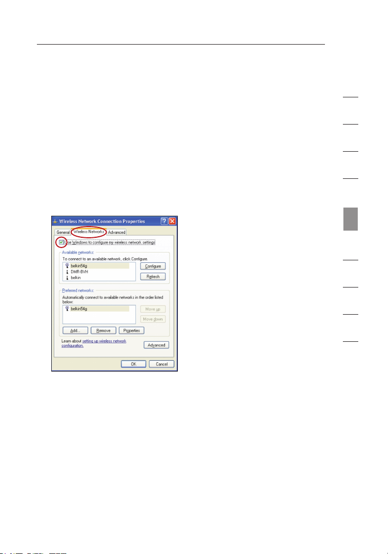
6362
Using the Web-Based Advanced User Interface
Setting up Windows XP Wireless Network Utility to use
WPA-PSK
In order to use WPA-PSK, ensure yo u are using the Win dow s Wireless
Network Util ity by doing the fo llo wing:
1. Und er Window s XP, click “S tar t > Control Pa nel > Network
Connections” .
2. Rig ht- click on “Wireless Network Connection Properties”, and
select “Properties”.
3. Cl icking on the “Wireless Networks” t ab will display the
following screen. Ensure t he “Use Windows to conf igu re my
wireless network settings” box is checked.
1
2
3
4
5
sec tion
6
7
8
9
10
6362
Page 66

Using the Web-Based Advanced User Interface
4. Un der the “Wireless Networks” tab, cl ick the “Configure ” button
and y ou will see the foll owi ng screen .
5. For a ho me or small business us er, selec t “WPA-PS K” under
“Network Authenticati on” .
Note: Se lect “WPA ” if you ar e using this c omp uter to connect to
a cor porate ne two rk tha t supports an aut hentication server su ch
as a radius server. Please c onsult yo ur network administra tor for
further information.
6. Sel ect “TKIP ” or “AES” und er “Data Encryption”. This setting wil l
have to be identical to t he Router that yo u set up.
7. Typ e your encryption key i n the “Network ke y” box .
Important: Enter your pre-shared k ey. This can be from eight to 63
characters and ca n be letters, numbers, or symbol s. This same k ey
must be used on all of the cli ents that you set up .
8. Cli ck “OK” to app ly settin gs.
64
Page 67

6564
Using the Web-Based Advanced User Interface
Using the Access Point Mode
Note: This ad vanced feature shou ld be employed by a dva nced users
only. The Ro ute r can be configu red to work as a wirel ess network
access point . U sing this mode w ill defeat the NAT IP sha ring feature
and DHCP ser ver . In Access Poin t ( AP) mode, the Route r w ill need to
be configure d w ith an IP addres s t hat is in the same sub net as the
rest of the net work that you wi ll bridge to. The defa ult IP address
is 192.168.2 .25 4 and subnet mas k i s 255.255.255.0. Th ese can be
customized f or your need.
1. En able the AP mo de my selecting “Enable” in the “Use as
Access Point o nly ” page . When you sel ect this option, you wi ll
be ab le to change the IP settings.
2. Se t your IP s ett ings t o match your n etw ork. Clic k “Apply
Changes”.
3. Co nnect a cable from t he “Modem” port o n the Router to your
existing network.
The Router i s n ow acting as an acc ess point. To acces s t he Router’s
Web-Based Ad van ced User Interfa ce again, type the IP add ress
you specifie d i nto your browser ’s navigation bar. You ca n set the
encryption s ett ings, MAC addres s f iltering, SSID, and
channel norm all y.
1
2
3
4
5
sec tion
6
7
8
9
10
6564
Page 68
Using the Web-Based Advanced User Interface
Wireless Range Extension and Bridging
Wireless ran ge extension and br idg ing works with the fol lowing models only:
F5D7231-4 Wi rel ess G Plus Route r
F5D7230-4 Wi rel ess G Router
F5D7130 Wire les s G Range Extend er/ Access Point
F5D7132 Wire les s G Universal Ra nge Extender
Please make sure to download the latest firmware version for the Router or Access
Point for optimal performance: http://web.belkin.com/support
What is a Wireless Bridge?
A wireless b rid ge is a “mode” i n w hich your Wireless Rou ter can directly
connect to a se condary Wireless Ac cess Point. Note th at you can only bridge
your Belkin Wireless G Router (model F5D7230-4,
F5D7231-4) t o a Belkin Wireless G Range Extender/Acce ss Point (model
F5D7131, F5D 713 0). We do not su ppo rt bridging with ac ces s points of other
manufacturer s a t this time. You ca n use the bridge mo de to extend the range
of your wire les s network, or ad d a n extension of your ne twork in another
area of your of fice or home wit hou t running cables.
Range Extension
Ran ge e xtension will extend the wireless coverage area in your hom e or
off ice. The example on the next page illustrates the use of bridgi ng t o extend
the ran ge of your wireless network. In this example, the Router is set up to
con nect to an Access Point located in another area. Laptops can ro am o r
mov e be tween the two wireless coverage areas.
66
Page 69

6766
Using the Web-Based Advanced User Interface
Adding Another Network Segment Wirelessly
Bridging an Acc ess Point to you r R outer allows you to ad d a network
segment in a not her area in the hom e or office without ru nning wires.
Connecting a ne twork switch or hub to the Access Poin t’s RJ45 jack will
allow a numb er of computers con nec ted to the switch a cce ss to the rest
of the netwo rk.
1
2
3
4
5
sec tion
6
7
8
9
10
6766
Page 70

Using the Web-Based Advanced User Interface
Setting Up a Bridge Between your Wireless Router and a
Secondary Access Point
Bridging your Belkin Router to a secondary Access Point requires that you
access the Router’s Advanced Setup Utility and enter the MAC address
of the Access Point in the appropriate area. There are also a few other
requirements.
1. Set your Access P oint to the sa me channe l as the Ro ute r. By
default, the R out er and Access Point cha nnels are set to cha nne l
11 at the factory. If you have never ch ang ed the channel, you
don’t need to do anything (f or more information on changing
channels, see pag e 48 of thi s User Manual).
2. Fin d the Access P oint’s MA C address on t he bottom of t he
Access Point. The re are two MAC addre sse s on the bo ttom labe l.
You w ill need the MAC add res s named “WLAN MAC Ad dre ss”.
The M AC addres s starts with 0030BD an d is followed by six
other numbers or letter s (i.e. 0030BD-XXXXXX). Write the M AC
address below. Go to the nex t step.
PLEASE BE SURE TO FOLLOW THE STEPS BELOW, CAREFULLY.
3. Place you r seconda ry Access Point w ithin ran ge of your Wir eless
Router and nea r the area whe re you want to exten d the range
or ad d the network segment. Typically, i ndoor ran ge should be
between 100 an d 200 feet.
4. Con nec t powe r to your Acce ss Point. Make su re the Access
Point is on and proceed t o the next ste p.
68
Page 71

6968
Using the Web-Based Advanced User Interface
5. Fro m a c omputer a lready co nne cted to your R outer, ac cess the
Advanced Setup Ut ility by opening your b rowser. I n the address
bar, type in “192.168.2 .1” . Do not ty pe in “www” or “http:// ”
before the num ber .
address, use t hat IP address.
6. You will see t he Router’s user interface in the browser window.
Click “Wireless B ridge” (2) on the left-hand side of the screen.
You w ill see the following s creen.
(1)
(2)
(3)
Note: If you ha ve changed your R outer’s I P
1
2
3
4
5
sec tion
6
7
8
9
10
7. Che ck the box tha t says “Enable ONLY spe cif ic Acc ess Points
to connec t” (1).
8. In the f ields nam ed “AP1” (3), type in t he MAC address of your
secondary Access Point. Wh en you have ty ped in the address,
click “Apply C han ges”.
9. Bri dgi ng is now s et up.
6968
Page 72

Using the Web-Based Advanced User Interface
Configuring the Firewall
Your Router is equipped with a fir ewall that will pro tec t your network from
a wide array of common hacker a tta cks including:
• IP Spoofin g
• SYN flood
• Land Attac k
• UDP floodi ng
• Ping of De ath (PoD)
• Tear Drop Att ack
• Denial of Ser vice (DoS)
• ICMP defec t
• IP with ze ro length
• RIP defect
• Smurf Atta ck
• Fragment f loo ding
• TCP Null S can
The firewall al so masks common por ts that are frequen tly used to attack
networks. Th ese ports appear to be “Stealth”, meaning th at for all intents
and purposes , t hey do not exist to a would-be hacker. Yo u can turn the
firewall fun cti on off if needed ; h owever, it is recom men ded that you leave
the firewall en abled. Disabling th e firewall protecti on will not leave your
network comp let ely vulnerable t o h acker attacks, but it is recommended
that you lea ve the firewall ena ble d.
70
Page 73

7170
Using the Web-Based Advanced User Interface
Configuring Internal Forwarding Settings
The “Virtual Se rvers” function wil l allow you to rout e e xternal (Internet)
calls for se rvi ces such as a we b s erver (port 80), FT P s erver (Port 21),
or other app lic ations through y our Router to your int ern al network.
Since your i nte rnal computers a re protected by a fire wal l, computers
outside your ne twork (over the Int ernet) cannot get t o t hem because
they cannot be “seen.” A list o f c ommon applications has been
provided in cas e you need to co nfi gure the “Virtual S erv er” function
for a specif ic application. You wi ll need to contact the application
vendor to fi nd out which port s ett ings you need.
Entering Settings into the Virtual Server
To enter set tin gs, enter the IP ad dress in the space pro vided for
the internal (s erver) machine, and the port(s) requir ed to pass. Then
select the p ort type (TCP or UD P), check the “Enable” bo x, and click
“Apply Chang es” . Each inbound p ort entry has two fiel ds with five
characters m axi mum per field th at allows a start and end port range,
e.g. [xxxxx] -[x xxxx]. For each ent ry, you can enter a si ngle port value
by filling i n t he two fields wi th the same value (e.g . [ 7500]-[7500]) or
a wide range of ports (e.g. [75 00] -[9000]). If you ne ed multiple single
port values or a combination of ra nges and a single v alu e, you must
use multiple en tries up to the max imum of 20 entries (e. g. 1. [7500][7500], 2. [ 802 3]-[8023], 3. [9 000 ]-[9000]). You can onl y pass one port
per internal IP address. Openin g p orts in your firewa ll can pose a
security ris k. You can enable a nd disable settings ve ry quickly. It is
recommended tha t you disable th e s ettings when you ar e n ot using a
specific app lic ation.
7170
1
2
3
4
5
sec tion
6
7
8
9
10
Page 74

Using the Web-Based Advanced User Interface
Setting Client IP Filters
The Router c an be configured to re strict access to th e I nternet, email, or
other networ k s ervices at speci fic days and times. Re str iction can be set f or
a single com put er, a range of c omp uters, or multiple com puters.
To restrict Int ernet access to a s ingle computer, for ex ample, enter the IP
address of t he computer you wis h t o restrict access t o i n the IP fields (1).
Next, enter “80 ” in both the po rt fields (2). S elect “Both” (3). Select “ Blo ck”
(4). You can also sele ct “Always” to block a cce ss all of the ti me. Select the
day to start on top (5), the time to start o n t op (6), th e day to end on the
bottom (7), and t he time to stop (8) on the botto m. Select “Enable” (9). C lick
“Apply Chang es” . The computer a t t he IP address you s pec ified will now be
blocked from In ternet access at th e times you specifi ed. Note: Be sure you
have selecte d t he correct time zon e under “Utilities> Sy stem Settings>
Time Zone”.
(1) (2)
(5)
(4) (7) (8) (9)
(3)
72
(6)
Page 75

7372
Using the Web-Based Advanced User Interface
Setting MAC Address Filtering
The MAC addr ess filter is a pow erf ul security feature th at allows you
to specify w hic h computers are all owed on the network . A ny computer
attempting t o a ccess the networ k t hat is not specifie d i n the filter list
will be deni ed access. When you en able this feature, you must enter
the MAC addr ess of each client (co mputer) on your net wor k to allow
network acce ss to each.
(1)
(2)
(3)
(4)
To enable th is feature, select “MA C Address Filtering ” a nd click
“Enable MAC Add ress Filtering” (1). Next, en ter the MAC address of
each compute r o n your network b y c licking in the spac e p rovided (2)
and entering th e MAC address of th e computer you want to add to the
list. Click “Ad d” (3), th en “Apply Changes” (4) to sav e t he settings.
You can have a MAC-address-filt eri ng list of up to 32 co mputers.
Note: You wi ll not be able to d ele te the MAC address of the computer
you are usin g t o access the Rou ter ’s administrative f unc tions (the
computer you ar e using now).
1
2
3
4
5
sec tion
6
7
8
9
10
7372
Page 76
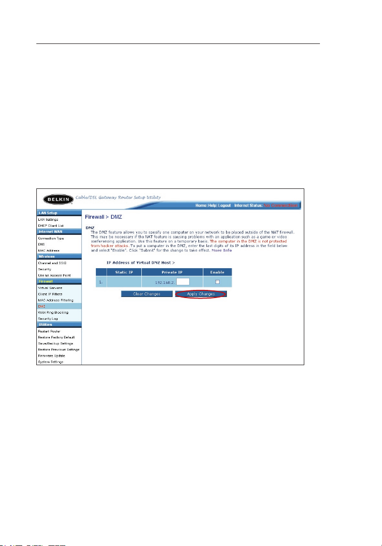
Using the Web-Based Advanced User Interface
Enabling the Demilitarized Zone (DMZ)
The DMZ feat ure allows you to s pec ify one computer on yo ur network to
be placed ou tsi de of the firewa ll. This may be necess ary if the firewall
is causing p rob lems with an app lic ation such as a gam e o r video
conferencing ap plication. Use t his feature on a tempo rar y basis. The
computer in the DMZ is NOT prot ect ed from hacker atta cks .
Note: If your ISP subscription pr ovid es you with additional public (WAN)
IP addr esses, additional computers can be placed outside the firew all
pro vide d each computer uses a different public (WAN) IP.
To put a com put er in the DMZ, e nte r the last digits o f i ts IP address in
the IP field an d select “Enable ”. Click “Apply Change s” for the change to
take effect.
74
Page 77

7574
Using the Web-Based Advanced User Interface
WAN Ping Blocking
Computer hac ker s use what is kn own as “pinging” to fi nd potential
victims on t he Internet. By pin gin g a specific IP add res s and receiving
a response f rom the IP address, a hacker can determin e t hat
something of in terest might be the re. The Router can be set up so it
will not res pon d to an ICMP pin g f rom the outside. Th is heightens the
level of sec uri ty of your Route r.
(1)
To turn off the ping response, select “Block ICMP Ping” (1) an d click
“Ap ply Changes”. The Router will not respond to an ICMP ping.
1
2
3
4
5
sec tion
6
7
8
9
10
7574
Page 78

Using the Web-Based Advanced User Interface
Utilities Tab
Thi s screen lets you manage dif fere nt paramete rs of the Router and perform
cer tain administra tive functions.
76
Page 79

7776
Using the Web-Based Advanced User Interface
Restarting the Router
Sometimes it m ay be necessary to rest art or reboot the Route r if it
begins working im properly. Restarting or reboot ing the Router will
NOT d elete any of your co nfi guration set tings.
Restarting the Router to Restore Normal Operation
1. Cli ck the “Restart
Router” button.
2. Th e followi ng
message will a ppe ar.
Click “OK”.
3. Th e followi ng messag e
will appear. R est arting
the R outer can take
up to 25 seconds. It
is im portant n ot to turn
off t he power to the
Router during
the r estart.
4. A 25-second countdow n will appear on the screen. Wh en the
countdown reaches zero, th e Router will be restar ted . The
Router’s home pag e shou ld appear automatically. If n ot, ty pe in
the R outer’s a ddr ess (d efa ult = 192.168.2.1) into th e navi gat ion
bar o f your browser.
1
2
3
4
5
sec tion
6
7
8
9
10
7776
Page 80

Using the Web-Based Advanced User Interface
Restoring Factory Default Settings
Using this o pti on will restore all of the settings in th e Router to the fac tor y
(default) se tti ngs. It is recom men ded that you back u p y our settings before
you restore all of the defaults .
1. Cl ick the “Restore
Defaults” button.
2. Th e followi ng
message will a ppe ar.
Click “OK”.
3. Th e followi ng messag e
will appear. R est oring
the d efaults i ncl udes
restarting the Ro uter.
It ca n take up t o
25 se conds. It is
important not to turn
the p ower to the
Router off dur ing
the r estart.
4. A 25-second countdow n will appear on the screen. Wh en the
countdown reaches zero, th e Router’ s defaults will b e rest ore d. The
Router’s home pag e shou ld appear automatically. If i t does not, type in
the R outer’s a ddr ess (d efa ult = 192.168.2.1) into th e navi gat ion bar of
your browser.
78
Page 81

7978
Using the Web-Based Advanced User Interface
Saving a Current Configuration
You can save yo ur current confi gur ation by using this fe ature. Saving
your configu rat ion will allow y ou to restore it later if your settings are
lost or chan ged . It is recommen ded that you back up y our current
configuratio n b efore performing a firmware update.
1. Cl ick “Save ”. A
window called “Fi le
Download” will op en.
Click “Save”.
2. A window will op en
that allows yo u to
select the loc ati on
where you want to
save the confi gur ation
file. Select a location .
You c an name the file
anything you w ant , or
use t he defaul t name
“Config”. Be s ure to
name the file so you
can l ocate it yourself
later. When yo u have
selected the l oca tion
and n ame of the file,
click “Save”.
1
2
3
4
5
sec tion
6
7
8
9
10
7978
Page 82

Using the Web-Based Advanced User Interface
3. Whe n the save is
complete, you wil l see
the f ollowing win dow.
Click “Close”.
The c onfiguration is
now s aved.
Restoring a Previous Configuration
This option wil l allow you to r est ore a previously sa ved configuration.
1. Cl ick “Brow se” . A window will open that allows y ou to select t he
location of th e configu rat ion file. All configuration files e nd with a
“.bin”. Locate th e conf igu ration fi le you want to restore and
double-click on i t.
80
Page 83

8180
Using the Web-Based Advanced User Interface
2. Yo u will be a ske d if you wa nt to continue. Click “ OK”.
3. A reminder window will ap pear. It will take up to 35 second s for
the c onfiguration restoration to co mpl ete. Clic k “OK”.
4. A 35-second countdow n will appear on the screen. Wh en the
countdown reaches zero, th e Router’ s configurat ion will be
restored. The Rou ter’s hom e page should appear au tom atically.
If no t, type in the Route r’s address (default = 192 .168.2.1) in to
the n avigation ba r of your b rowser.
1
2
3
4
5
sec tion
6
7
8
9
10
8180
Page 84

Using the Web-Based Advanced User Interface
Updating the Firmware
From time to ti me, Belkin may r ele ase new versions of th e Router’s
firmware. Fi rmw are updates cont ain feature improvemen ts and fixes to
problems tha t m ay exist. When B elk in releases new fir mwa re, you can
download the fi rmware from the Bel kin update website and update your
Router’s fir mwa re to the latest ve rsion.
Searching for a New Version of Firmware
From http:// www .belkin.com/supp ort /do wnloads.asp, typ e i n the
Bel kin part number “F5D7230-4” on the “Search” field. Click “Searc h”.
From the res ult s page, click “F 5D7 230-4 Firmware upda te -
North Americ a”.
82
Page 85

8382
Using the Web-Based Advanced User Interface
Downloading a New Version of Firmware
You will now be taken to the do wnl oad page of “F5D723 0-4 Firmware
update - Nor th America”.
1. To download the new ve rsi on of firmware, click t he downlo ad
logo ( ).
2. A window will open that allows you to select the location where
you want to save the firmware file. Select a location. You can
nam e the file anything you want , or use the default name. Be sure
to save the file in a place where you ca n locate it yourself later.
Note: We sugge st saving this to your desktop to mak e it easy
to lo cate the file. When you have selected the l oca tion,
click “Save”.
1
2
3
4
5
sec tion
6
7
8
9
10
8382
Page 86

Using the Web-Based Advanced User Interface
3. When th e save is comp let e, you will see the following window.
Click “Close”.
The downl oad of the fi rmware is com plete. To upd ate the fi rmw are, follow t he
next steps i n “ Updating the Rou ter ’s Firmware”.
Updating the Router’s Firmware
1. In the “Firmware
Update” page, cli ck
“Browse”. A wi ndo w
will open that allows
you t o select the
location of th e
firmware update f ile.
2. Br owse to the fi rmware
file you downl oad ed.
Select the fil e by
double-click ing on the
file name.
84
Page 87

8584
Using the Web-Based Advanced User Interface
3. Th e “Upd ate Firmw are ”
box w ill now display
the l ocation a nd name
of th e firmwar e file
you j ust selec ted .
Click “Update”.
4. You will be as ked if
you a re sure you
want to contin ue.
Click “OK”.
5. You will see o ne
more message. Thi s
message tells you
that the Route r may
not r espond fo r as
long as one minute
as th e firmwar e is
loaded into the R outer
and t he Router is
rebooted. Click “ OK”.
6. A 60-second countdown will ap pear on the sc reen. Whe n the
countdown reaches zero, th e Router’ s firmware update will be
complete. The Rou ter’s hom e page should appear au tom atically.
If no t, type in the Route r’s address (default = 192 .168.2.1) in to
the n avigation ba r of your b rowser.
1
2
3
4
5
sec tion
6
7
8
9
10
The firmware update is comple te.
8584
Page 88

Using the Web-Based Advanced User Interface
Changing System Settings
The “System Set tings” page is w her e you can enter a n ew administrator
password, se t t he time zone, en abl e remote management , a nd turn on and
off the NAT fun ction of the Rou ter .
Setting or Changing the Administrator Password
The Router s hip s with NO passwo rd entered. If you wis h t o add a
password
your passwor d and keep it in a safe place, as you will need it if you need to log
into the Router in the future. It is also recommended that you set a password if
you plan to use the remote management feature of your Router.
Changing the Login Time-Out Setting
The login ti me- out option allow s y ou to set the perio d o f time that you
can be logge d i nto the Router’s We b-Based Advanced Us er Interface.
The timer st art s when there has be en no activity. For ex ample, you have
made some ch ang es in the advanc ed setup interface, th en left your
computer alo ne without clicking “L ogout”. Assuming th e t ime-out is set to
10 minutes, the n 10 minutes aft er you leave, the logi n s ession will expire.
You will hav e t o log into the R out er again to make an y m ore changes. The
login time-o ut option is for se cur ity purposes and th e d efault is set to 10
minutes.
Note: Only o ne com puter can be log ged into the Router’s Web -Based
Advanced Use r I nterface at one tim e.
Setting the Time and Time Zone
The Router k eep s time by connec tin g to a Simple Netwo rk Time Protocol
(SNTP) serve r. This allows the Rou ter to synchronize the system clock
to the globa l I nternet. The syn chr onized clock in the Ro uter is used to
record the s ecu rity log and con tro l client filtering. Se lect the time zone
that you res ide in. If you resi de in an area that obs erv es daylight saving,
then place a ch eck mark in the box next to “Automatic all y Adjust Daylight
Saving”. The sy stem clock may n ot update immediately. Al low at least 15
minutes for the Router to conta ct the time servers on th e Internet and get
a response. You cannot set the clo ck yourself.
for greater sec uri ty, you can set a p ass word here. Write do wn
86
Page 89

8786
Using the Web-Based Advanced User Interface
Enabling Remote Management
Before you e nab le this advanced fe ature of your Belki n R outer, MAKE
SURE YOU HAV E S ET THE ADMINISTR ATO R P ASSWORD. Remote
management a llo ws you to make c han ges to your Router’ s s ettings
from anywher e o n the Internet. The re are two methods of remotely
managing the Ro uter. The first is to allow access to the Router from
anywhere on the Internet by sel ect ing “Any IP address ca n remotely
manage the R out er”. By typing i n y our WAN IP address fro m any
computer on the Internet, you w ill be presented with a l ogin screen
where you ne ed to type in the p ass word of your Router . T he second
method is to al low a specific I P a ddress only to remo tel y manage the
Router. This is more secure, bu t l ess convenient. To use this method,
enter the IP ad dress you know y ou will be accessing t he Router from
in the space pr ovided and selec t “ Only this IP addres s c an remotely
manage the R out er”. Before you ena ble this function, it is STRONGLY
RECOMMENDED tha t you set your a dmi nistrator password. Le aving the
password emp ty will potentially op en your Router to i ntr usion.
1
2
3
4
5
sec tion
6
7
8
9
10
8786
Page 90

Using the Web-Based Advanced User Interface
Enabling/Disabling Network Address Translation (NAT)
Note: This advanced feature should be modified by advanced users only.
NAT is the m eth od by which the Rou ter shares the sing le IP address
assigned by you r ISP with the o the r computers on your ne twork and is
enabled by d efa ult. NAT should onl y be disabled if yo ur ISP assigns you
multiple IP add resses or you ne ed NAT disabled for an ad vanced system
configuratio n. If you have a si ngl e IP address and yo u t urn NAT off,
the computer s o n your network w ill not be able to acc ess the Internet.
Other proble ms may also occur. Tur ning off NAT will d isa ble your firewall
functions.
Enabling/Disabling UPnP
UPnP (Univer sal Plug-and-Play) is yet another advance d f eature offered
by your Belk in Router. It is a tec hnology that offers se amless operation of
voice messag ing , video messagin g, games, and other ap pli cations that
are UPnP-com pli ant. Some applic ati ons require the Rou ter ’s firewall to
be configure d i n a specific way to operate properly. Thi s usually requires
opening TCP and UDP ports. An a ppl ication that is UPn P-c ompliant has
the ability to communicate with th e Router, basically “t elling” the Router
which way it ne eds the firewall co nfigured. The Route r s hips with the
UPnP feature di sabled. If you a re using any applicati ons that are
UPnP-complia nt, and wish to tak e a dvantage of the UPn P f eatures,
you can enab le the UPnP feature . S imply select “Enabl e” in the “UPnP
Enabling” se cti on of the “Utili tie s” page. Click “App ly Changes” to save
the change.
88
Page 91

8988
Using the Web-Based Advanced User Interface
1
2
Enabling/Disabling Auto Firmware Update
This innovation provides the Router with the built-in capability to automatically
check for a new version of firmware and alert you that the new firmware
is available. When you log into the Router’s Web-Based Advanced User
Interface, the Router will perform a check to see if new firmware is available.
If so, you will be notified. You can choose to download the new version or
ignore it. The Router ships with this feature enabled. If you want to disable it,
select “Disable” and click “Apply Changes”.
3
4
5
sec tion
6
7
8
9
10
8988
Page 92
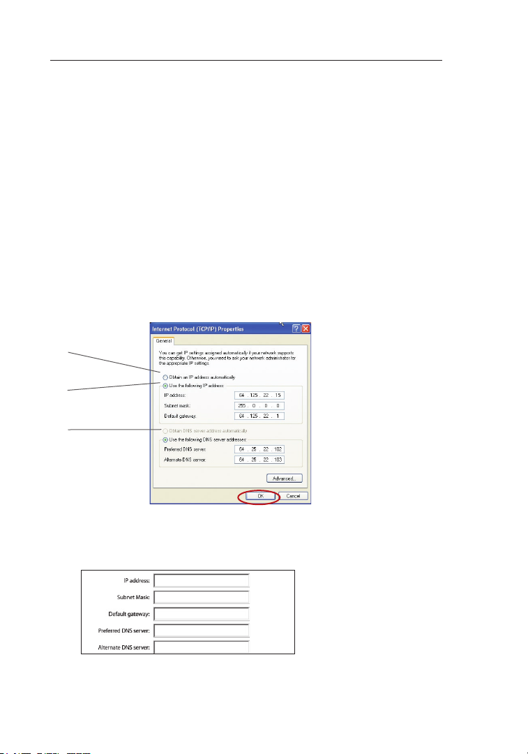
Manually Configuring Network Settings
In order for your computer to properly communicate with your Router, you will need
to change your PC’s TCP/IP settings to DHCP.
Manually Configuring Network Adapters in Windows 2000, NT, XP, or Vista
1.
Click “Start”, “Settings”, then “C ontrol Pa nel ”.
2. Do uble-click o n the “Network and d ial -up conne cti ons” i con (Windows
2000) or the “Network” icon (Windows XP or Vista).
3. Ri ght-click on the “Local Area Con nec tion” ass oci ated w ith your
network adapter a nd sel ect “Propert ies ” from the dro p-down me nu.
4. In the “Local Ar ea Con nec tion Prop ert ies” wind ow, click “Internet
Protocol (TCP/IP)” and cli ck the “Properties” button. The fol lowing
screen will ap pea r:
(1)
(2)
(3)
5. If “Use the following IP address” (2) is selected, your Router will need to
be set up for a static IP connection type. Write the address information in
the table below. You will need to enter this information into the Router.
6. If not already selected, select “Obtain an IP address automatically” (1)
and “Obtain DNS server address automatically” (3). Click “OK”.
Your network adapter(s) are now configured for use with the Router.
90
Page 93

9190
Manually Configuring Network Settings
Manually Configuring Network Adapters in Windows 98SE or Me
1.
Right-cl ick on “My Net wor k Neig hbo rhood” an d select
“Properties” from the d rop -down men u.
2. Sel ect “TCP/ IP -> settings” f or your installed network adapter.
You w ill see the following w indow.
(1)
(3)
(2)
3. If “Specify an IP addr ess ” is selected, your Rou ter will need
to be set up for a static I P connection type. Write t he addres s
information in th e tabl e below. You w ill need to en ter this
information into the Ro ute r.
1
2
3
4
5
6
sec tion
7
8
9
10
4. Wr ite in the IP addres s and subnet m ask from the “ IP Addres s”
tab (3).
5. Cli ck the “Gateway” tab (2). Write the gateway address down i n
the c hart.
6. Cl ick the “DNS Configuration” tab (1). Write t he DNS
address(es) in th e char t.
7. If not already s elected, select “O bta in IP address automatically”
in th e “IP Address” tab. Cli ck “OK”.
9190
Page 94

Manually Configuring Network Settings
Restart the computer. When the computer restarts, your network
adapter(s) are now configured for use with the Router.
Set up the c omp uter that is con nec ted to the cable or DS L modem FIRST
using these ste ps. You can also us e these steps to ad d c omputers to your
Router after th e Router has bee n s et up to connect to th e Internet.
Manually Configuring Network Adapters in Mac OS up to 9.x
In order for yo ur computer to p rop erly communicate wi th your Router, you
will need to ch ange your Mac co mpu ter’s TCP/IP settin gs to DHCP.
1. Pu ll down the Ap ple me nu. Select “Control Panels” a nd
select “TCP/IP”.
2. You will see t he TCP/IP control panel. S ele ct “Et her net Built -In ” or
“Ethernet” in the “Conn ect via:” drop-down menu (1).
(1)
(2)
3. Nex t to “Configure” (2), if “ Manually” is selected , your Router will
need to be set u p for a sta tic IP connection type. Wr ite the address
information in the table below . Y ou wil l n eed to en ter th is inf ormation
into the Route r.
4. If not a lready se t, at “Configure:”, choose “Using D HCP
Server”. This wil l tell the computer to obtain an I P address
from the Route r.
92
Page 95

9392
Manually Configuring Network Settings
1
2
5. Cl ose the window. If y ou made any ch ang es, the following
window will ap pea r. Cli ck “Save”.
Restart the co mpu ter. When the computer restarts, yo ur networ k
settings are n ow config ure d for use w ith the Router.
3
4
5
6
sec tion
7
8
9
10
9392
Page 96

Manually Configuring Network Settings
Manually Configuring Network Adapters in Mac OS X
1. Cl ick on the “Sy stem P ref erences” ico n.
2. Se lect “Net wor k” (1) fr om the “System Preferences” menu.
(1)
3. Se lect “Bui lt- in Eth ern et” (2) n ext to “Show” in the Network menu.
(2)
(3)
(4)
94
(5)
Page 97

9594
Manually Configuring Network Settings
4. Se lect the “TCP/IP” tab (3). Next to “Configur e:” (4), you should
see “ Manually” or “Usin g DHCP”. If yo u do not, c hec k the
PPPoE tab
selected. If i t is, you w ill need to co nfi gure y our Router for a
PPPoE connection type u sin g your user na me and password.
5. If “Manuall y” is selected, your Ro ute r will need to be set up for
a sta tic IP connection type. Write th e address information in t he
table below. Y ou will need t o enter this i nformation into
the R outer.
6. If not already s elected, select “U sin g DHCP” next t o
“Configure:” (4), then click “Apply No w”.
Your network adapter(s) are now configured for use with the Router.
(5) to make su re that “Connect using PPP oE” is NOT
1
2
3
4
5
6
sec tion
7
8
9
10
9594
Page 98

Recommended Web Browser Settings
In most case s, you will not nee d t o make any changes to your web
browser’s se tti ngs. If you are hav ing trouble accessi ng the Internet or
the Web-Base d A dvanced User Int erf ace, then change yo ur browser’s
settings to the recommended set tin gs in this section.
Internet Explorer 4.0 or Higher
1.
St art your web b rowser. S ele ct “Tools ” then “Internet Options”.
2. In the “ Internet Options” scr een, ther e are three se lections: “N ever
dial a connect ion ”, “Di al whenever a net work conn ect ion is not
present”, and “Al ways d ial my default co nnection”. I f you can m ake
a sel ection, s ele ct “Ne ver dial a con nec tion”. If you cannot ma ke a
selection, go to the next st ep.
3. Un der the “Internet Options” screen, click on “Connecti ons ” and
select “LAN Se tti ngs…”.
96
Page 99

9796
Recommended Web Browser Settings
4. Mak e sure there a re no check ma rks next to any of the
displayed options: “Automatically detect settings”, “Use
automatic configurati on script”, and “ Use a proxy se rver”. Cl ick
“OK”. Then cli ck “OK” again in the “Internet Options” page.
Netscape® Navigator® 4.0 or Higher
1.
St art Netsc ape . Click on “Ed it” then “Preferen ces ”.
2. In the “Preferences” window, click on “Advance d” then select
“Proxies”. In the “Prox ies ” window, select “Direct c onnection to
the I nternet”.
1
2
3
4
5
6
7
sec tion
8
9
10
9796
Page 100

Troubleshooting
Problem:
I nst allation CD does not au tomatically start.
Solution:
If th e CD-ROM does not st art the Easy I nst all Wi zar d automat ica lly,
it co uld be that the comp ute r is running o ther a ppl ications tha t are
interfering with the CD drive.
1. If t he Eas y Install Wizard screen do es not appear within 15 —20
seconds, open up your CD-ROM drive by double-clic kin g on the
“My C omputer” ico n that is l ocated on your desktop.
2. Ne xt, double-c lic k on the CD -RO M driv e that the Eas y Install
Wizard Software C D has been placed in to s tart t he installat ion .
3. Th e Easy Install Wi zard shou ld start within a few seconds. If,
instead, a win dow appea rs showing the fi les on the CD, doubl eclick on the icon labeled “E asyInstall.exe”.
4. If the Easy I nst all Wi zar d still does n ot sta rt, referenc e the
section titled “M anually C onfiguring N etwork Se tti ngs” ( pag e 90
of th is User Manual) for an alternate setup method.
98
 Loading...