

Page 1
RADIO TEST REPORT
REPORT NO.: RE920221R04A
MODEL NO.: F5D7000
RECEIVED: Feb. 21, 2003
TESTED: Feb. 20~ Feb. 24, 2003
APPLICANT: Belkin Corporation
ADDRESS:
501 WEST WALNUT STREET COMPTON,
CA 90220
ISSUED BY: Advance Data Technology Corporation
LAB LOCATION: No. 47 14th Ling, Chia Pau Tsuen, Linkou
Hsiang, Taipei, Taiwan, R.O.C.
This test report consists of 54 pages in total. It may be duplicated completely for legal use
with the approval of the applicant. It should not be reproduced except in full, without the
written approval of our laboratory. The client should not use it to claim product endorsement
by NVLAP or any U.S. government agencies. The test results in the report only apply to the
tested sample.
0528
ILAC MRA
Report No.: RE920221R04A 1 Issued: Mar. 14, 2003
Reference No.: RE920221R04
Page 2

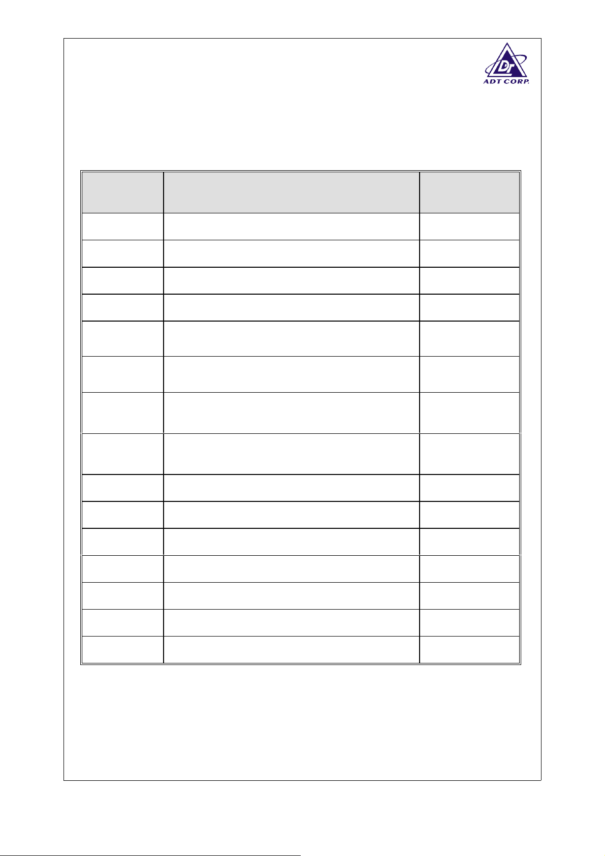
TABLE OF CONTENTS
1. CERTIFICATION ....................................................................................................................... 4
2. GENERAL INFORMATION....................................................................................................... 5
2.1 GENERAL DESCRIPTION OF EUT ..........................................................................................5
2.2 DESCRIPTION OF TEST MODES ............................................................................................6
2.3 GENERAL DESCRIPTION OF APPLIED STANDARDS...........................................................6
2.4 DESCRIPTION OF SUPPORT UNITS ......................................................................................7
2.5 CONFIGURATION OF SYSTEM UNDER TEST .......................................................................7
2.6 LIST OF MEASUREMENTS ......................................................................................................8
3. TEST PROCEDURES AND RESULTS..................................................................................... 9
TRANSMITTER PARAMETERS ..............................................................................................................9
3.1 EFFECTIVE RADIATED POWER (RADIATED)........................................................................9
3.1.1 LIMITS OF EFFECTIVE RADIATED POWER ...........................................................................9
3.1.2 TEST PROCEDURES................................................................................................................9
3.1.3 DEVIATION FROM TEST STANDARD......................................................................................9
3.1.4 TEST SETUP .............................................................................................................................9
3.1.5 TEST RESULTS (A).................................................................................................................10
3.1.6 TEST RESULTS (B).................................................................................................................11
3.2 EFFECTIVE RADIATED POWER (CONDUCTED) .................................................................12
3.2.1 LIMITS OF EFFECTIVE RADIATED POWER .........................................................................12
3.2.2 TEST PROCEDURES..............................................................................................................12
3.2.3 DEVIATION FROM TEST STANDARD....................................................................................12
3.2.4 TEST SETUP ...........................................................................................................................12
3.2.5 TEST RESULTS (A).................................................................................................................13
3.2.6 TEST RESULTS (B).................................................................................................................14
3.3 PEAK POWER DENSITY (DSSS EQUIPMENT) (RADIATED)...............................................15
3.3.1 LIMIT OF PEAK POWER DENSITY ........................................................................................15
3.3.2 TEST PROCEDURES..............................................................................................................15
3.3.3 DEVIATION FROM TEST STANDARD....................................................................................15
3.3.4 TEST SETUP ...........................................................................................................................15
3.3.5 TEST RESULTS (A).................................................................................................................16
3.3.6 TEST RESULTS (B).................................................................................................................17
3.4 PEAK POWER DENSITY (DSSS EQUIPMENT) (CONDUCTED) ..........................................18
3.4.1 LIMIT OF PEAK POWER DENSITY ........................................................................................18
3.4.2 TEST PROCEDURES..............................................................................................................18
3.4.3 DEVIATION FROM TEST STANDARD....................................................................................18
3.4.4 TEST SETUP ...........................................................................................................................18
3.4.5 TEST RESULTS (A).................................................................................................................19
3.4.6 TEST RESULTS (B).................................................................................................................20
3.5 FREQUENCY RANGE (DSSS EQUIPMENT) (RADIATED) ...................................................21
3.5.1 LIMIT OF FREQUENCY RANGE.............................................................................................21
3.5.2 TEST PROCEDURES..............................................................................................................21
3.5.3 DEVIATION FROM TEST STANDARD....................................................................................21
3.5.4 TEST SETUP ...........................................................................................................................21
3.5.5 TEST RESULTS (A).................................................................................................................22
3.5.6 TEST RESULTS (B).................................................................................................................24
3.6 FREQUENCY RANGE (DSSS EQUIPMENT) (CONDUCTED) ..............................................26
3.6.1 LIMIT OF FREQUENCY RANGE.............................................................................................26
Report No.: RE920221R04A 2 Issued: Mar. 14, 2003
Reference No.: RE920221R04
Page 3

3.6.2 TEST PROCEDURES..............................................................................................................26
3.6.3 DEVIATION FROM TEST STANDARD....................................................................................26
3.6.4 TEST SETUP ...........................................................................................................................26
3.6.5 TEST RESULTS (A).................................................................................................................27
3.6.6 TEST RESULTS (B).................................................................................................................29
3.7 TRANSMITTER SPURIOUS EMISSIONS (RADIATED).........................................................31
3.7.1 LIMITS OF TRANSMITTER SPURIOUS EMISSIONS............................................................31
3.7.2 TEST PROCEDURES..............................................................................................................31
3.7.3 DEVIATION FROM TEST STANDARD....................................................................................31
3.7.4 TEST SETUP ...........................................................................................................................31
3.7.5 TEST RESULTS.......................................................................................................................32
3.7.6 TEST RESULTS (A).................................................................................................................33
3.7.7 TEST RESULTS (B).................................................................................................................37
3.8 TRANSMITTER SPURIOUS EMISSIONS (CONDUCTED) ....................................................41
3.8.1 LIMITS OF TRANSMITTER SPURIOUS EMISSIONS............................................................41
3.8.2 TEST PROCEDURES..............................................................................................................41
3.8.3 DEVIATION FROM TEST STANDARD....................................................................................41
3.8.4 TEST SETUP ...........................................................................................................................41
3.8.5 TEST RESULTS (A).................................................................................................................42
3.8.6 TEST RESULTS (B).................................................................................................................44
RECEIVER PARAMETERS....................................................................................................................46
3.9 RECEIVER SPURIOUS RADIATION (RADIATED).................................................................46
3.9.1 LIMIT OF RECEIVER SPURIOUS RADIATION ......................................................................46
3.9.2 TEST PROCEDURES..............................................................................................................46
3.9.3 DEVIATION FROM TEST STANDARD....................................................................................46
3.9.4 TEST SETUP ...........................................................................................................................46
3.9.5 TEST RESULTS.......................................................................................................................47
3.9.6 TEST RESULTS (A).................................................................................................................48
3.9.7 TEST RESULTS (B).................................................................................................................49
3.10 RECEIVER SPURIOUS RADIATION (CONDUCTED)............................................................50
3.10.1 LIMIT OF RECEIVER SPURIOUS RADIATION ......................................................................50
3.10.2 TEST PROCEDURES..............................................................................................................50
3.10.3 DEVIATION FROM TEST STANDARD....................................................................................50
3.10.4 TEST SETUP ...........................................................................................................................50
3.10.5 TEST RESULTS.......................................................................................................................51
4. PHOTOGRAPHS OF THE TEST CONFIGURATION............................................................. 53
5. INFORMATION ON THE TESTING LABORATORIES ........................................................... 54
Report No.: RE920221R04A 3 Issued: Mar. 14, 2003
Reference No.: RE920221R04
Page 4
1. CERTIFICATION
PRODUCT : 2.4GHz wireless PCI
MODEL NO. : F5D7000
BRAND NAME : Belkin
APPLICANT :
Belkin Corporation
STANDARDS : EN 300 328-2 (07-2000)
We, Advance Data Technology Corporation, hereby certify that one sample of the
designation has been tested in our facility from Feb. 20~ Feb. 24, 2003. The test
record, data evaluation and Equipment Under Test (EUT) configurations represented
herein are true and accurate accounts of the measurements of the sample's EMC
characteristics under the conditions herein specified.
Report No.: RE920221R04A 4 Issued: Mar. 14, 2003
Reference No.: RE920221R04
Page 5
2. GENERAL INFORMATION
2.1 GENERAL DESCRIPTION OF EUT
PRODUCT 2.4GHz wireless PCI
MODEL NO.
SOURCE VOLTAGE
F5D7000
V
= 230 V
nom
= 207 V
min
max
= 253
POWER SUPPLY 3.3VDC from host equipment
RATED RF OUTPUT
POWER
MODULATION TYPE
18.69dBm (Measured Max. Average)
22.87dBm (Measured Max. Peak)
CCK, QPSK, DBPSK (DSSS), OFDM
BIT RATE OF
TRANSMITTER
up to 54Mbps
OPERATING FREQUENCY 2.412GHz ~ 2.472GHz
NUMBER OF CHANNEL 13
CHANNEL SPACING 5MHz
L.O. FREQUENCY VCO freq.=2/3 fundamental freq.
ANTENNA TYPE
TEMPERATURE RANGE
Dipole antenna
0℃ ~ 55℃
DATA CABLE NA
I/O PORTS
NA
ASSOCIATED DEVICES NA
NOTE:
1. The EUT operates in the 2.4GHz frequency spectrum with throughput of up to 54Mbps.
2. The EUT complies with IEEE 802.11g draft standards, and backwards compatible with IEEE
802.11b products.
3. For more detailed features description, please refer to the manufacturer's specifications or User's
Manual.
Report No.: RE920221R04A 5 Issued: Mar. 14, 2003
Reference No.: RE920221R04
Page 6

2.2 DESCRIPTION OF TEST MODES
The EUT (2.4GHz wireless PCI) has been tested under operating and standby
condition. Software used to control the EUT for staying in continuous transmitting
and receiving mode is programmed. Channel 1, 7, 10 and 13 are chosen for
testing to fulfill the requirement of frequency spectrum usage in each country.
Two test result were presented in the following sections, test result A is for
transfer rate 11Mbps with CCK technique and test result B is for transfer rate
54Mbps with OFDM technique
2.3 GENERAL DESCRIPTION OF APPLIED STANDARDS
The EUT is a 2.4GHz wireless PCI, according to the specifications of the
manufacturers, it must comply with the requirements of the following standards:
EN 300 328-2 (07-2000)
All tests have been performed and recorded as per the above standards.
Report No.: RE920221R04A 6 Issued: Mar. 14, 2003
Reference No.: RE920221R04
Page 7
2.4 DESCRIPTION OF SUPPORT UNITS
The EUT has been tested as an independent unit together with other necessary
accessories or support units. The following support units or accessories were used to
form a representative test configuration during the tests.
NO. PRODUCT BRAND MODEL NO. SERIAL NO. FCC ID
PERSONAL
1
COMPUTER
2 LCD MONITOR ADI LD-522N 1140A1T00100365A FCC DoC APPROVED
3 KEYBOARD BTC 5121W H013001162 E5XKB5121WTH0110
4 PS2 MOUSE HP M-S48a LZC20508276AW JNZ201213
NO. SIGNAL CABLE DESCRIPTION OF THE ABOVE SUPPORT UNITS
1NA
2 1.8 m braid shielded wire, terminated with VGA connector via metallic frame, w/o core.
HP Brio BA410 SG12902766 FCC DoC APPROVED
3 1.6 m foil shielded wire, terminated with PS/2 connector via metallic frame, w/o core.
4 1.8 m Non shielded wire, terminated with PS/2 connector via drain wire, w/o core.
NOTE: All power cords of the above support units are non shielded (1.8m).
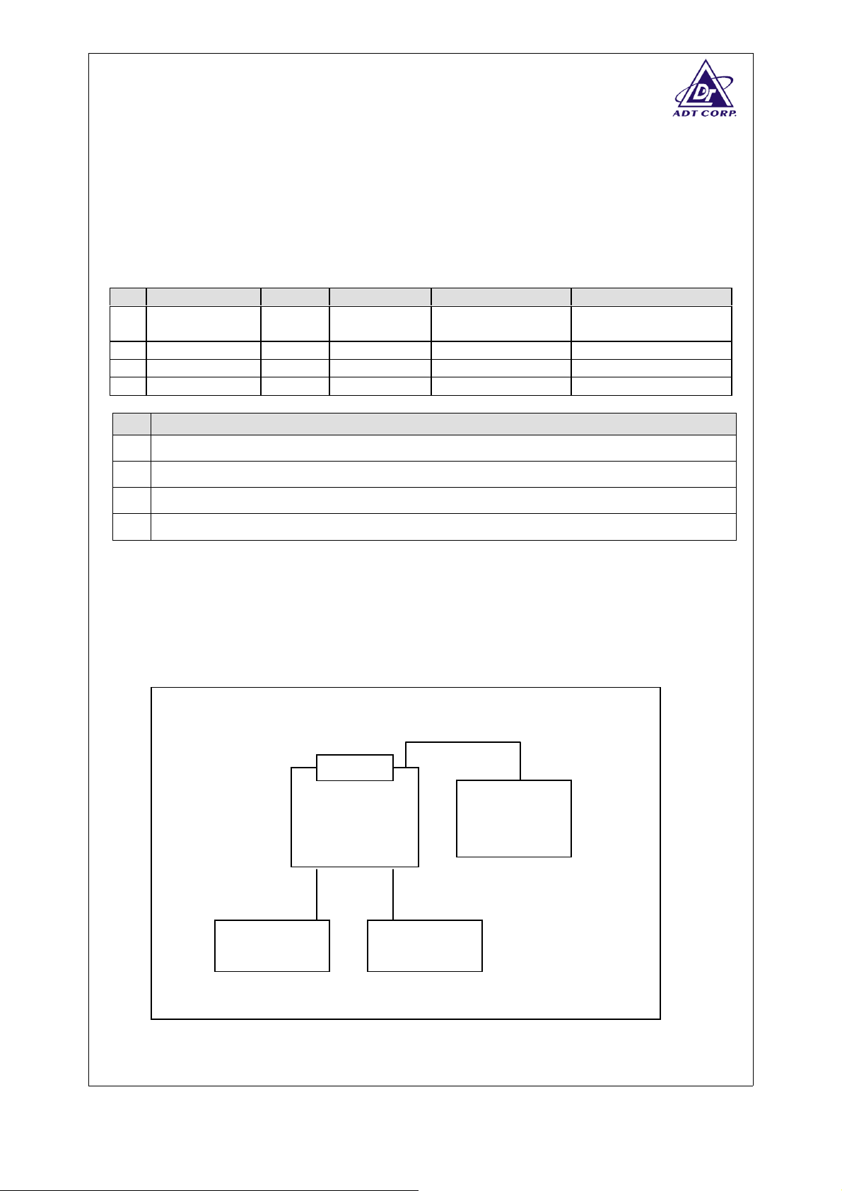
2.5 CONFIGURATION OF SYSTEM UNDER TEST
EUT
PERSONAL PC
MONITOR
MOUSE KEYBOARD
Report No.: RE920221R04A 7 Issued: Mar. 14, 2003
Reference No.: RE920221R04
Page 8
2.6 LIST OF MEASUREMENTS
Clause Test Parameter Remarks
TRANSMITTER PARAMETERS
7.2.1 Effective Radiated Power Applicable
7.2.1 Effective Conducted Power Applicable
7.2.2 Peak Power Density (FHSS Equipment) Not Applicable
7.2.2
7.2.2
Peak Power Density
(DSSS Equipment – Radiated)
Peak Power Density
(DSSS Equipment – Conducted)
7.2.3 Frequency Range of Equipment Using FHSS
Applicable
Applicable
Not Applicable
Modulation
7.2.4 Frequency Range of Equipment Using Other
Forms Of Modulation
Applicable
See Note 2
7.2.5 Spurious Emissions (Operating – Radiated) Applicable
7.2.5 Spurious Emissions (Standby – Radiated) See Note 1
7.2.5 Spurious Emissions (Operating – Conducted) Applicable
7.2.5 Spurious Emissions (Standby – Conducted) See Note 1
RECEIVER PARAMETERS
9.1 Spurious Emissions (Radiated) Applicable
9.2 Spurious Emissions (Conducted) Applicable
NOTE:
1. The emission of the transmitter on standby mode is equal to that of receiving mode.
2. Additionally, channel 10 was recorded, for showing effective use of frequency spectrum on France.
Report No.: RE920221R04A 8 Issued: Mar. 14, 2003
Reference No.: RE920221R04
Page 9
3. TEST PROCEDURES AND RESULTS
TRANSMITTER PARAMETERS
3.1 EFFECTIVE RADIATED POWER (RADIATED)
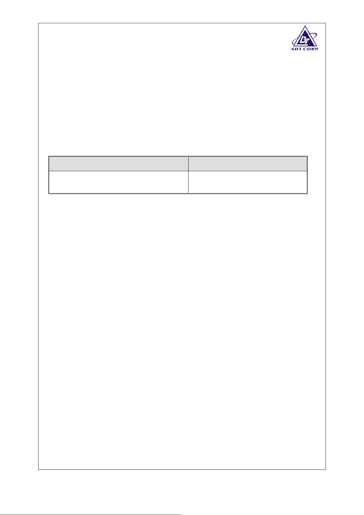
3.1.1 LIMITS OF EFFECTIVE RADIATED POWER
Condition
Under all test conditions
3.1.2 TEST PROCEDURES
Please refer to item 7 of the standard.
3.1.3 DEVIATION FROM TEST STANDARD
No deviation
3.1.4 TEST SETUP
Limit
Av: 20 dBm / -10 dBW
Pk: 23 dBm / -7 dBW
The test setup has been constructed as the normal use condition. The EUT has
been connected with PC and placed on the turn table. Controlling software has
been activated to set the EUT on specific status.
Report No.: RE920221R04A 9 Issued: Mar. 14, 2003
Reference No.: RE920221R04
Page 10

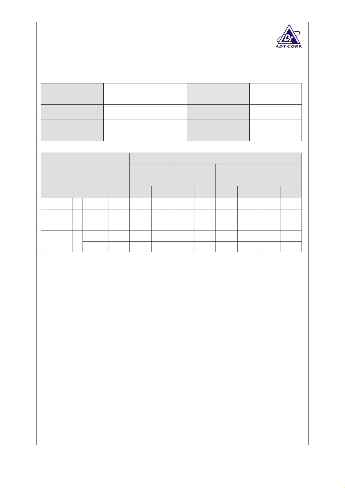
3.1.5 TEST RESULTS (A)
EUT
Modulation bit rate
Environmental
Conditions
TEST CONDITION
Tnom(℃)
Tmin(℃)
Tmax(℃)
20 Vnom(v) 230 V 11.37 9.26 11.50 10.05 12.65 11.48 14.28 12.78
Vmin(v) 207 V 10.33 7.58 12.16 10.08 12.74 11.05 14.40 12.27
0
Vmax(v) 253 V 10.33 7.58 12.16 10.08 12.74 11.05 14.40 12.27
Vmin(v) 207 V 6.33 3.46 7.98 5.83 8.76 6.92 10.57 8.32
55
Vmax(v) 253 V 6.33 3.46 7.98 5.83 8.76 6.92 10.57 8.32
2.4GHz wireless PCI
11Mbps
20deg. C,66%RH
(CH1)
2412 MHz
PK AV PK AV PK AV PK AV
Model
Duty cycle of EUT
Tested By
F5D7000
100 %
Hardaway Lee
TRANSMITTER PEAK POWER (dBm)
(CH7)
2442 MHz
(CH10)
2457 MHz
2472 MHz
(CH13)
Report No.: RE920221R04A 10 Issued: Mar. 14, 2003
Reference No.: RE920221R04
Page 11

3.1.6 TEST RESULTS (B)
EUT
Modulation bit rate
Environmental
Conditions
TEST CONDITION
Tnom(℃)
Tmin(℃)
Tmax(℃)
20 Vnom(v) 230 V 14.64 9.31 16.68 10.82 17.46 11.66 18.35 12.22
Vmin(v) 207 V 19.61 14.04 22.49 17.17 22.44 18.09 22.87 18.69
0
Vmax(v) 253 V 19.61 14.04 22.49 17.17 22.44 18.09 22.87 18.69
Vmin(v) 207 V 9.58 4.24 12.64 6.46 12.58 6.37 13.82 7.20
55
Vmax(v) 253 V 9.58 4.24 12.64 6.46 12.58 6.37 13.82 7.20
2.4GHz wireless PCI
54Mbps
20deg. C,66%RH
(CH1)
2412 MHz
PK AV PK AV PK AV PK AV
Model
Duty cycle of EUT
Tested By
F5D7000
100 %
Hardaway Lee
TRANSMITTER PEAK POWER (dBm)
(CH7)
2442 MHz
(CH10)
2457 MHz
2472 MHz
(CH13)
Report No.: RE920221R04A 11 Issued: Mar. 14, 2003
Reference No.: RE920221R04
Page 12
3.2 EFFECTIVE RADIATED POWER (CONDUCTED)
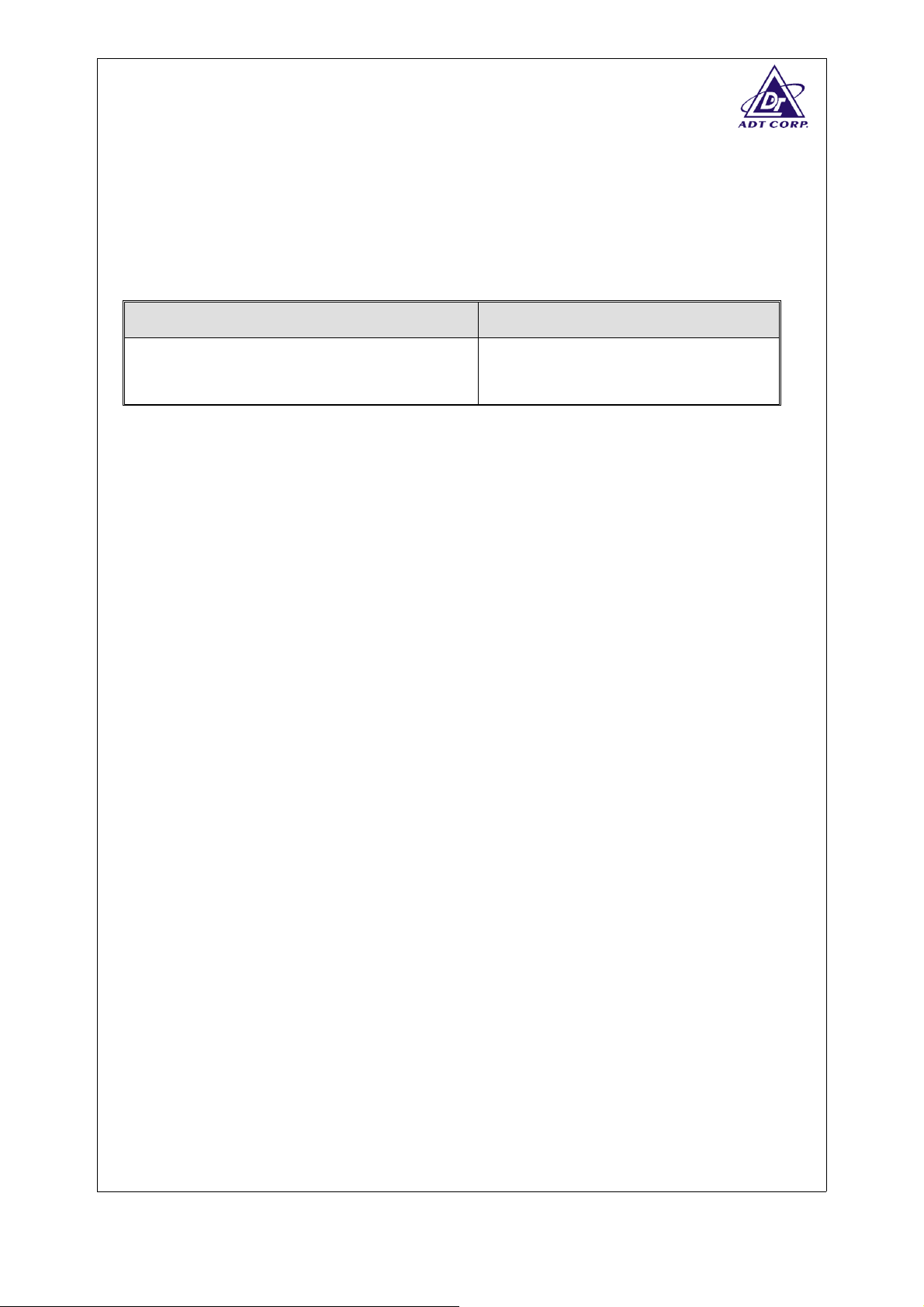
3.2.1 LIMITS OF EFFECTIVE RADIATED POWER
Condition
Under all test conditions
3.2.2 TEST PROCEDURES
Please refer to item 7 of the standard.
3.2.3 DEVIATION FROM TEST STANDARD
No deviation
3.2.4 TEST SETUP
Limit
Av: 20 dBm / -10 dBW
Pk: 23 dBm / -7 dBW
The test setup has been constructed as the normal use condition. The EUT has
been connected with PC and placed on the turn table. Controlling software has
been activated to set the EUT on specific status.
Report No.: RE920221R04A 12 Issued: Mar. 14, 2003
Reference No.: RE920221R04
Page 13
3.2.5 TEST RESULTS (A)
EUT
Modulation bit rate
Environmental
Conditions
TEST CONDITION
Tnom(℃)
Tmin(℃)
Tmax(℃)
20 Vnom(v) 230 V 9.32 4.61 9.22 5.23 8.30 5.75 8.26 5.05
Vmin(v) 207 V 8.28 2.93 9.88 5.26 8.39 5.32 8.38 4.54
0
Vmax(v) 253 V 8.28 2.93 9.88 5.26 8.39 5.32 8.38 4.54
Vmin(v) 207 V 4.28 -1.19 5.70 1.01 4.41 1.19 4.55 0.59
55
Vmax(v) 253 V 4.28 -1.19 5.70 1.01 4.41 1.19 4.55 0.59
2.4GHz wireless PCI
11Mbps
20deg. C,66%RH
(CH1)
2412 MHz
PK AV PK AV PK AV PK AV
Model
Duty cycle of EUT
Tested By
F5D7000
100 %
Hardaway Lee
TRANSMITTER PEAK POWER (dBm)
(CH7)
2442 MHz
(CH10)
2457 MHz
2472 MHz
(CH13)
Report No.: RE920221R04A 13 Issued: Mar. 14, 2003
Reference No.: RE920221R04
Page 14

3.2.6 TEST RESULTS (B)
EUT
Modulation bit rate
Environmental
Conditions
TEST CONDITION
Tnom(℃)
Tmin(℃)
Tmax(℃)
20 Vnom(v) 230 V 3.92 2.90 5.34 4.97 5.71 5.23 6.43 5.27
Vmin(v) 207 V 11.39 10.13 13.65 13.02 13.19 14.16 13.71 13.01
0
Vmax(v) 253 V 11.39 10.13 13.65 13.02 13.19 14.16 13.71 13.01
Vmin(v) 207 V 1.36 0.33 3.80 3.11 3.33 2.44 4.40 2.75
55
Vmax(v) 253 V 1.36 0.33 3.80 3.11 3.33 2.44 4.40 2.75
2.4GHz wireless PCI
54Mbps
20deg. C,66%RH
(CH1)
2412 MHz
PK AV PK AV PK AV PK AV
Model
Duty cycle of EUT
Tested By
F5D7000
100 %
Hardaway Lee
TRANSMITTER PEAK POWER (dBm)
(CH7)
2442 MHz
(CH10)
2457 MHz
2472 MHz
(CH13)
Report No.: RE920221R04A 14 Issued: Mar. 14, 2003
Reference No.: RE920221R04
Page 15
3.3 PEAK POWER DENSITY (DSSS EQUIPMENT) (RADIATED)
3.3.1 LIMIT OF PEAK POWER DENSITY
Condition
Under all test conditions
Limit
10dBm / 1 MHz (DSSS)
3.3.2 TEST PROCEDURES
Please refer to item 7 of the standard.
3.3.3 DEVIATION FROM TEST STANDARD
No deviation
20dBm / 100 KHz (FHSS)
3.3.4 TEST SETUP
The EUT has been programmed to continuously transmit in certain channel during
test.
Report No.: RE920221R04A 15 Issued: Mar. 14, 2003
Reference No.: RE920221R04
Page 16
3.3.5 TEST RESULTS (A)
EUT
Modulation bit rate
Environmental
Conditions
2.4GHz wireless PCI
11Mbps
20deg. C,66%RH
Channel
Channel
Number
Frequency
RF Power
(dBm/KHz)
(MHz)
1
7
10
13
NOTE
1. For equipment using FHSS modulation, the power density shall be limit to –10dBW(100mW) per
100kHz e.i.r.p.
2. For equipment using other types of modulation, the peak power shall be limit to -20dBW(10mW)
per MHz e.i.r.p.
2415.2401 0.53/1000 10/1000 PASS
2443.3997 1.59/1000 10/1000 PASS
2454.0034 2.71/1000 10/1000 PASS
2474.4944 2.42/1000 10/1000 PASS
Model
Tested By
Limit
(dBm/kHz)
F5D7000
Hardaway Lee
PASS/FAIL
Report No.: RE920221R04A 16 Issued: Mar. 14, 2003
Reference No.: RE920221R04
Page 17

3.3.6 TEST RESULTS (B)
EUT
Modulation bit rate
Environmental
Conditions
2.4GHz wireless PCI
54Mbps
20deg. C,66%RH
Channel
Channel
Number
Frequency
RF Power
(dBm/KHz)
(MHz)
1
7
10
13
NOTE
1. For equipment using FHSS modulation, the power density shall be limit to –10dBW(100mW) per
100kHz e.i.r.p.
2. For equipment using other types of modulation, the peak power shall be limit to -20dBW(10mW)
per MHz e.i.r.p.
2417.0539 1.49/1000 10/1000 PASS
2446.7407 -0.60/1000 10/1000 PASS
2461.9411 -0.06/1000 10/1000 PASS
2476.8503 0.19/1000 10/1000 PASS
Model
Tested By
Limit
(dBm/kHz)
F5D7000
Hardaway Lee
PASS/FAIL
Report No.: RE920221R04A 17 Issued: Mar. 14, 2003
Reference No.: RE920221R04
Page 18

3.4 PEAK POWER DENSITY (DSSS EQUIPMENT) (CONDUCTED)
3.4.1 LIMIT OF PEAK POWER DENSITY
Condition
Under all test conditions
Limit
10dBm / 1 MHz (DSSS)
3.4.2 TEST PROCEDURES
Please refer to item 7 of the standard.
3.4.3 DEVIATION FROM TEST STANDARD
No deviation
20dBm / 100 KHz (FHSS)
3.4.4 TEST SETUP
The EUT has been programmed to continuously transmit in certain channel during
test.
Report No.: RE920221R04A 18 Issued: Mar. 14, 2003
Reference No.: RE920221R04
Page 19

3.4.5 TEST RESULTS (A)
EUT
Modulation bit rate
Environmental
Conditions
2.4GHz wireless PCI
11Mbps
20deg. C,66%RH
Channel
Channel
Number
Frequency
RF Power
(dBm/KHz)
(MHz)
1
7
10
13
NOTE
1. For equipment using FHSS modulation, the power density shall be limit to –10dBW(100mW) per
100kHz e.i.r.p.
2. For equipment using other types of modulation, the peak power shall be limit to -20dBW(10mW)
per MHz e.i.r.p.
2415.2378 2.17/1000 10/1000 PASS
2445.3583 2.21/1000 10/1000 PASS
2454.5733 2.65/1000 10/1000 PASS
2474.4330 2.36/1000 10/1000 PASS
Model
Tested By
Limit
(dBm/kHz)
F5D7000
Hardaway Lee
PASS/FAIL
Report No.: RE920221R04A 19 Issued: Mar. 14, 2003
Reference No.: RE920221R04
Page 20

3.4.6 TEST RESULTS (B)
EUT
Modulation bit rate
Environmental
Conditions
2.4GHz wireless PCI
54Mbps
20deg. C,66%RH
Channel
Channel
Number
Frequency
RF Power
(dBm/KHz)
(MHz)
1
7
10
13
NOTE
1. For equipment using FHSS modulation, the power density shall be limit to –10dBW(100mW) per
100kHz e.i.r.p.
2. For equipment using other types of modulation, the peak power shall be limit to -20dBW(10mW)
per MHz e.i.r.p.
2416.7533 -7.46/1000 10/1000 PASS
2446.8409 -5.121000 10/1000 PASS
2461.8033 -7.66/1000 10/1000 PASS
2476.9148 -7.741000 10/1000 PASS
Model
Tested By
Limit
(dBm/kHz)
F5D7000
Hardaway Lee
PASS/FAIL
Report No.: RE920221R04A 20 Issued: Mar. 14, 2003
Reference No.: RE920221R04
Page 21

3.5 FREQUENCY RANGE (DSSS EQUIPMENT) (RADIATED)
3.5.1 LIMIT OF FREQUENCY RANGE
Condition Country Limit
France
Under all test conditions
EU
3.5.2 TEST PROCEDURES
Please refer to item 7 of the standard.
3.5.3 DEVIATION FROM TEST STANDARD
No deviation
FL >= 2446.5MHz
F
<= 2483.5 MHz
H
FL >= 2400.0MHz
F
<= 2483.5 MHz
H
3.5.4 TEST SETUP
The EUT and probe antenna was placed into the temperature oven. The probe has
to be connected with spectrum analyzer. The power source of the EUT has to be
connected with the power supply for voltage change. The frequency has to be
recorded for the right and left end above threshold of highest and lowest channel
respectively.
Report No.: RE920221R04A 21 Issued: Mar. 14, 2003
Reference No.: RE920221R04
Page 22

3.5.5 TEST RESULTS (A)
EUT
Channel
Environmental
Conditions
2.4GHz wireless PCI
10 ~ 13
(for France)
20deg. C, 66%RH
Model
Tested By
F5D7000
Hardaway Lee
FREQUENCY (MHz)
TEST CONDITIONS
Lowest Highest
Tnom 20℃
Tmin 0℃
Tmax 55℃
Measured frequencies (lowest and highest) FL = 2449.57 FH = 2479.45
Vnom(v) 230 2449.57 2479.45
Vmin(v) 207 2449.88 2479.25
Vmax(v) 253 2449.88 2479.25
Vmin(v) 207 2450.18 2478.53
Vmax(v) 253 2450.18 2478.53
NOTE
1. For France market, only channel 10 ~ 13 are allowed. So, only lowest edge of channel 10 and
highest edge of channel 13 under extreme condition are recorded in the above table.
2. The E.U.T is a stand alone radio device (see the clause 6.2.2). The host equipment is powered
by the AC adapter. So, the AC power is used as the extreme voltage source.
Report No.: RE920221R04A 22 Issued: Mar. 14, 2003
Reference No.: RE920221R04
Page 23

EUT
Channel
Environmental
Conditions
2.4GHz wireless PCI
1 ~ 13
(for other EU countries)
20deg. C, 66%RH
Model
Tested By
F5D7000
Hardaway Lee
FREQUENCY (MHz)
TEST CONDITIONS
Lowest Highest
Tnom 20℃
Tmin 0℃
Tmax 55℃
Measured frequencies (lowest and highest) FL = 2404.57 FH = 2479.45
Vnom(v) 230 2404.57 2479.45
Vmin(v) 207 2405.10 2479.25
Vmax(v) 253 2405.10 2479.25
Vmin(v) 207 2405.37 2478.53
Vmax(v) 253 2405.37 2478.53
NOTE
1. For EU market, only channel 1 ~ 13 are allowed. So, only lowest edge of channel 1 and highest
edge of channel 13 under extreme condition are recorded in the above table.
2. The E.U.T is a stand alone radio device (see the clause 6.2.2). The host equipment is powered by
the AC Adapter. So, the AC power is used as the extreme voltage source. (see clause 6.3.2.1)
Report No.: RE920221R04A 23 Issued: Mar. 14, 2003
Reference No.: RE920221R04
Page 24

3.5.6 TEST RESULTS (B)
EUT
Channel
Environmental
Conditions
2.4GHz wireless PCI
10 ~ 13
(for France)
20deg. C, 66%RH
Model
Tested By
F5D7000
Hardaway Lee
FREQUENCY (MHz)
TEST CONDITIONS
Lowest Highest
Tnom 20℃
Tmin 0℃
Tmax 55℃
Measured frequencies (lowest and highest) FL = 2446.58 FH = 2482.25
Vnom(v) 230 2447.67 2481.27
Vmin(v) 207 2446.58 2482.25
Vmax(v) 253 2446.58 2482.25
Vmin(v) 207 2447.97 2481.05
Vmax(v) 253 2447.97 2481.05
NOTE
1. For France market, only channel 10 ~ 13 are allowed. So, only lowest edge of channel 10 and
highest edge of channel 13 under extreme condition are recorded in the above table.
2. The E.U.T is a stand alone radio device (see the clause 6.2.2). The host equipment is powered
by the AC adapter. So, the AC power is used as the extreme voltage source.
Report No.: RE920221R04A 24 Issued: Mar. 14, 2003
Reference No.: RE920221R04
Page 25

EUT
Channel 1 ~ 13
Environmental
Conditions
2.4GHz wireless PCI
(for other EU countries)
20deg. C, 66%RH
Model
Tested By
F5D7000
Hardaway Lee
FREQUENCY (MHz)
TEST CONDITIONS
Lowest Highest
Tnom 20℃
Tmin 0℃
Tmax 55℃
Measured frequencies (lowest and highest) FL = 2401.83 FH = 2482.25
Vnom(v) 230 2402.98 2481.27
Vmin(v) 207 2401.83 2482.25
Vmax(v) 253 2401.83 2482.25
Vmin(v) 207 2403.02 2481.05
Vmax(v) 253 2403.02 2481.05
NOTE
1. For EU market, only channel 1 ~ 13 are allowed. So, only lowest edge of channel 1 and highest
edge of channel 13 under extreme condition are recorded in the above table.
2. The E.U.T is a stand alone radio device (see the clause 6.2.2). The host equipment is powered by
the AC Adapter. So, the AC power is used as the extreme voltage source. (see clause 6.3.2.1)
Report No.: RE920221R04A 25 Issued: Mar. 14, 2003
Reference No.: RE920221R04
Page 26

3.6 FREQUENCY RANGE (DSSS EQUIPMENT) (CONDUCTED)
3.6.1 LIMIT OF FREQUENCY RANGE
Condition Country Limit
France
Under all test conditions
EU
3.6.2 TEST PROCEDURES
Please refer to item 7 of the standard.
3.6.3 DEVIATION FROM TEST STANDARD
No deviation
FL >= 2446.5MHz
F
<= 2483.5 MHz
H
FL >= 2400.0MHz
F
<= 2483.5 MHz
H
3.6.4 TEST SETUP
The EUT and probe antenna was placed into the temperature oven. The probe has
to be connected with spectrum analyzer. The power source of the EUT has to be
connected with the power supply for voltage change. The frequency has to be
recorded for the right and left end above threshold of highest and lowest channel
respectively.
Report No.: RE920221R04A 26 Issued: Mar. 14, 2003
Reference No.: RE920221R04
Page 27

3.6.5 TEST RESULTS (A)
EUT
Channel
Environmental
Conditions
2.4GHz wireless PCI
10 ~ 13
(for France)
20deg. C, 66%RH
Model
Tested By
F5D7000
Hardaway Lee
FREQUENCY (MHz)
TEST CONDITIONS
Lowest Highest
Tnom 20℃
Tmin 0℃
Tmax 55℃
Measured frequencies (lowest and highest) FL = 2449.57 FH = 2479.45
Vnom(v) 230 2449.57 2479.45
Vmin(v) 207 2449.88 2479.25
Vmax(v) 253 2449.88 2479.25
Vmin(v) 207 2450.18 2478.53
Vmax(v) 253 2450.18 2478.53
NOTE
1. For France market, only channel 10 ~ 13 are allowed. So, only lowest edge of channel 10 and
highest edge of channel 13 under extreme condition are recorded in the above table.
2. The E.U.T is a stand alone radio device (see the clause 6.2.2). The host equipment is powered
by the AC adapter. So, the AC power is used as the extreme voltage source.
Report No.: RE920221R04A 27 Issued: Mar. 14, 2003
Reference No.: RE920221R04
Page 28

EUT
Channel
Environmental
Conditions
2.4GHz wireless PCI
1 ~ 13
(for other EU countries)
20deg. C, 66%RH
Model
Tested By
F5D7000
Hardaway Lee
FREQUENCY (MHz)
TEST CONDITIONS
Lowest Highest
Tnom 20℃
Tmin 0℃
Tmax 55℃
Measured frequencies (lowest and highest) FL = 2404.57 FH = 2479.45
Vnom(v) 230 2404.57 2479.45
Vmin(v) 207 2405.10 2479.25
Vmax(v) 253 2405.10 2479.25
Vmin(v) 207 2405.37 2478.53
Vmax(v) 253 2405.37 2478.53
NOTE
1. For EU market, only channel 1 ~ 13 are allowed. So, only lowest edge of channel 1 and highest
edge of channel 13 under extreme condition are recorded in the above table.
2. The E.U.T is a stand alone radio device (see the clause 6.2.2). The host equipment is powered by
the AC Adapter. So, the AC power is used as the extreme voltage source. (see clause 6.3.2.1)
Report No.: RE920221R04A 28 Issued: Mar. 14, 2003
Reference No.: RE920221R04
Page 29

3.6.6 TEST RESULTS (B)
EUT
Channel
Environmental
Conditions
2.4GHz wireless PCI
10 ~ 13
(for France)
20deg. C, 66%RH
Model
Tested By
F5D7000
Hardaway Lee
FREQUENCY (MHz)
TEST CONDITIONS
Lowest Highest
Tnom 20℃
Tmin 0℃
Tmax 55℃
Measured frequencies (lowest and highest) FL = 2446.58 FH = 2482.25
Vnom(v) 230 2447.67 2481.27
Vmin(v) 207 2446.58 2482.25
Vmax(v) 253 2446.58 2482.25
Vmin(v) 207 2447.97 2481.05
Vmax(v) 253 2447.97 2481.05
NOTE
1. For France market, only channel 10 ~ 13 are allowed. So, only lowest edge of channel 10 and
highest edge of channel 13 under extreme condition are recorded in the above table.
2. The E.U.T is a stand alone radio device (see the clause 6.2.2). The host equipment is powered
by the AC adapter. So, the AC power is used as the extreme voltage source.
Report No.: RE920221R04A 29 Issued: Mar. 14, 2003
Reference No.: RE920221R04
Page 30

EUT
Channel
Environmental
Conditions
2.4GHz wireless PCI
1 ~ 13
(for other EU countries)
20deg. C, 66%RH
Model
Tested By
F5D7000
Hardaway Lee
FREQUENCY (MHz)
TEST CONDITIONS
Lowest Highest
Tnom 20℃
Tmin 0℃
Tmax 55℃
Measured frequencies (lowest and highest) FL = 2401.83 FH = 2482.25
Vnom(v) 230 2402.98 2481.27
Vmin(v) 207 2401.83 2482.25
Vmax(v) 253 2401.83 2482.25
Vmin(v) 207 2403.02 2481.05
Vmax(v) 253 2403.02 2481.05
NOTE
1. For EU market, only channel 1 ~ 13 are allowed. So, only lowest edge of channel 1 and highest
edge of channel 13 under extreme condition are recorded in the above table.
2. The E.U.T is a stand alone radio device (see the clause 6.2.2). The host equipment is powered by
the AC Adapter. So, the AC power is used as the extreme voltage source. (see clause 6.3.2.1)
Report No.: RE920221R04A 30 Issued: Mar. 14, 2003
Reference No.: RE920221R04
Page 31

3.7 TRANSMITTER SPURIOUS EMISSIONS (RADIATED)
3.7.1 LIMITS OF TRANSMITTER SPURIOUS EMISSIONS
Transmitter limits for narrowband spurious emissions
Frequency Range Operating Limit Standby Limit
30MHz ~ 1GHz -36dBm -57dBm
Above 1GHz ~ 12.75GHz -30dBm -47dBm
1.8~1.9GHz 5.15~5.3GHz -47dBm -47dBm
3.7.2 TEST PROCEDURES
Please refer to item 7 of the standard.
3.7.3 DEVIATION FROM TEST STANDARD
No deviation
3.7.4 TEST SETUP
For the actual test configuration, please refer to the related Item in this test report
( Photographs of the Test Configuration ).
Report No.: RE920221R04A 31 Issued: Mar. 14, 2003
Reference No.: RE920221R04
Page 32

3.7.5 TEST RESULTS
EUT
Frequency Range
Environmental
Conditions
2.4GHz wireless PCI
Below 1GHz
25deg. C , 70%RH
Model
Tested By
F5D7000
Hardaway Lee
SPURIOUS EMISSION LEVEL
Frequency
(MHz)
84.11 H -70.7 -36.00 -34.70
100.34 H -68.6 -36.00 -32.60
174.47 H -69.1 -36.00 -33.10
174.47 V -68.6 -36.00 -32.60
200.44 V -67.0 -36.00 -31.00
250.22 V -69.7 -36.00 -33.70
479.56 H -64.0 -36.00 -28.00
479.56 V -66.9 -36.00 -30.90
Antenna
Polarization
Level
(dBm)
Limit
(Dbm)
Margin
527.25 H -68.4 -36.00 -32.40
527.25 V -70.8 -36.00 -34.80
664.73 V -63.3 -36.00 -27.30
997.19 H -55.5 -36.00 -19.50
NOTE: The emission behavior belongs to narrowband spurious emission.
Report No.: RE920221R04A 32 Issued: Mar. 14, 2003
Reference No.: RE920221R04
Page 33

3.7.6 TEST RESULTS (A)
EUT
2.4GHz wireless PCI
Model
F5D7000
Channel 1
Environmental
Conditions
25deg. C , 70%RH
Tested By
Hardaway Lee
SPURIOUS EMISSION LEVEL
Frequency
(MHz)
1607.64 H -72.7 -30.00 -42.70
1607.93 V -70.7 -30.00 -40.70
3215.91 V -61.0 -30.00 -31.00
3215.93 H -57.7 -30.00 -27.70
4823.84 H -72.5 -30.00 -42.50
4823.88 V -70.1 -30.00 -40.10
6431.33 H -59.4 -30.00 -29.40
6431.95 V -60.6 -30.00 -30.60
7235.53 V -67.5 -30.00 -37.50
7236.44 H -68.1 -30.00 -38.10
9648.35 V -64.4 -30.00 -34.40
9648.47 H -64.7 -30.00 -34.70
Antenna
Polarization
Level
(dBm)
Limit
(dBm)
Margin
NOTE: The emission behavior belongs to narrowband spurious emission.
Report No.: RE920221R04A 33 Issued: Mar. 14, 2003
Reference No.: RE920221R04
Page 34

EUT
2.4GHz wireless PCI
Model
F5D7000
Channel 7
Environmental
Conditions
25deg. C , 70%RH
Tested By
Hardaway Lee
SPURIOUS EMISSION LEVEL
Frequency
(MHz)
1627.93 V -69.5 -30.00 -39.50
1627.94 H -72.7 -30.00 -42.70
3255.92 V -63.7 -30.00 -33.70
3256.98 H -67.0 -30.00 -37.00
4883.87 V -70.0 -30.00 -40.00
4883.91 H -71.4 -30.00 -41.40
6512.05 V -61.5 -30.00 -31.50
6513.42 H -61.1 -30.00 -31.10
7325.81 H -66.0 -30.00 -36.00
7326.43 V -66.0 -30.00 -36.00
8139.32 V -58.1 -30.00 -28.10
9768.41 H -64.9 -30.00 -34.90
Antenna
Polarization
Level
(dBm)
Limit
(dBm)
Margin
NOTE: The emission behavior belongs to narrowband spurious emission.
Report No.: RE920221R04A 34 Issued: Mar. 14, 2003
Reference No.: RE920221R04
Page 35

EUT
2.4GHz wireless PCI
Model
F5D7000
Channel 10
Environmental
Conditions
25deg. C , 70%RH
Tested By
Hardaway Lee
SPURIOUS EMISSION LEVEL
Frequency
(MHz)
1637.49 H -72.1 -30.00 -42.10
1637.96 V -69.5 -30.00 -39.50
3275.91 V -65.2 -30.00 -35.20
3275.92 H -62.0 -30.00 -32.00
4913.89 H -71.5 -30.00 -41.50
4913.89 V -69.5 -30.00 -39.50
6551.56 V -59.9 -30.00 -29.90
6551.64 H -59.8 -30.00 -29.80
7370.62 H -65.0 -30.00 -35.00
7370.76 V -65.8 -30.00 -35.80
9827.93 H -64.4 -30.00 -34.40
Antenna
Polarization
Level
(dBm)
Limit
(dBm)
Margin
NOTE: The emission behavior belongs to narrowband spurious emission.
Report No.: RE920221R04A 35 Issued: Mar. 14, 2003
Reference No.: RE920221R04
Page 36

EUT
2.4GHz wireless PCI
Model
F5D7000
Channel 13
Environmental
Conditions
25deg. C , 70%RH
Tested By
Hardaway Lee
SPURIOUS EMISSION LEVEL
Frequency
(MHz)
1647.93 H -76.8 -30.00 -46.80
1647.95 V -83.7 -30.00 -53.70
3295.90 H -68.4 -30.00 -38.40
3295.93 V -74.6 -30.00 -44.60
4943.91 V -68.9 -30.00 -38.90
4944.29 H -72.5 -30.00 -42.50
6591.48 H -60.8 -30.00 -30.80
7416.41 H -65.5 -30.00 -35.50
7416.87 V -66.0 -30.00 -36.00
9887.64 H -64.8 -30.00 -34.80
9888.86 V -64.0 -30.00 -34.00
Antenna
Polarization
Level
(dBm)
Limit
(dBm)
Margin
NOTE: The emission behavior belongs to narrowband spurious emission.
Report No.: RE920221R04A 36 Issued: Mar. 14, 2003
Reference No.: RE920221R04
Page 37

3.7.7 TEST RESULTS (B)
EUT
2.4GHz wireless PCI
Model F5D7000
Channel 1
Environmental
Conditions
25deg. C , 70%RH
Tested By
Hardaway Lee
SPURIOUS EMISSION LEVEL
Frequency
(MHz)
1607.48 H -85.6 -30.00 -55.60
1607.94 V -75.0 -30.00 -45.00
3215.91 V -61.3 -30.00 -31.30
3215.93 H -76.7 -30.00 -46.70
4823.90 H -64.2 -30.00 -34.20
4832.47 V -72.5 -30.00 -42.50
6431.89 V -61.3 -30.00 -31.30
6431.92 H -66.2 -30.00 -36.20
7235.28 H -67.6 -30.00 -37.60
7257.79 V -66.9 -30.00 -36.90
9650.47 H -65.1 -30.00 -35.10
9668.79 V -65.4 -30.00 -35.40
Antenna
Polarization
Level
(dBm)
Limit
(dBm)
Margin
NOTE: The emission behavior belongs to narrowband spurious emission.
Report No.: RE920221R04A 37 Issued: Mar. 14, 2003
Reference No.: RE920221R04
Page 38

EUT
2.4GHz wireless PCI
Model
F5D7000
Channel 7
Environmental
Conditions
25deg. C , 70%RH
Tested By
Hardaway Lee
SPURIOUS EMISSION LEVEL
Frequency
(MHz)
1627.62 H -85.1 -30.00 -55.10
1628.28 V -85.2 -30.00 -55.20
3256.56 H -77.4 -30.00 -47.40
4069.41 V -74.6 -30.00 -44.60
4883.35 V -72.1 -30.00 -42.10
4883.88 H -56.5 -30.00 -26.50
6512.82 V -68.2 -30.00 -38.20
6512.91 H -67.9 -30.00 -37.90
7325.03 V -66.6 -30.00 -36.60
7326.83 H -65.7 -30.00 -35.70
9766.89 V -64.8 -30.00 -34.80
9767.39 H -65.3 -30.00 -35.30
Antenna
Polarization
Level
(dBm)
Limit
(dBm)
Margin
NOTE: The emission behavior belongs to narrowband spurious emission.
Report No.: RE920221R04A 38 Issued: Mar. 14, 2003
Reference No.: RE920221R04
Page 39

EUT
2.4GHz wireless PCI
Model
F5D7000
Channel 10
Environmental
Conditions
25deg. C , 70%RH
Tested By
Hardaway Lee
SPURIOUS EMISSION LEVEL
Frequency
(MHz)
1637.92 H -86.6 -30.00 -56.60
1637.92 V -77.9 -30.00 -47.90
3275.92 H -72.6 -30.00 -42.60
3275.92 V -66.6 -30.00 -36.60
4912.93 V -72.8 -30.00 -42.80
4913.88 H -64.5 -30.00 -34.50
6551.86 V -61.2 -30.00 -31.20
7371.81 H -65.0 -30.00 -35.00
7373.42 V -65.0 -30.00 -35.00
9825.72 V -64.3 -30.00 -34.30
9828.04 H -64.9 -30.00 -34.90
Antenna
Polarization
Level
(dBm)
Limit
(dBm)
Margin
NOTE: The emission behavior belongs to narrowband spurious emission.
Report No.: RE920221R04A 39 Issued: Mar. 14, 2003
Reference No.: RE920221R04
Page 40

EUT
2.4GHz wireless PCI
Model
F5D7000
Channel 13
Environmental
Conditions
25deg. C , 70%RH
Tested By
Hardaway Lee
SPURIOUS EMISSION LEVEL
Frequency
(MHz)
1648.00 V -86.4 -30.00 -56.40
1648.25 H -75.2 -30.00 -45.20
3295.89 V -76.8 -30.00 -46.80
3296.18 H -68.9 -30.00 -38.90
4942.51 V -72.1 -30.00 -42.10
4943.62 H -71.8 -30.00 -41.80
6591.87 V -66.8 -30.00 -36.80
6592.43 H -61.2 -30.00 -31.20
7414.65 V -65.0 -30.00 -35.00
7415.75 H -65.5 -30.00 -35.50
8240.06 V -64.6 -30.00 -34.60
9888.24 H -64.9 -30.00 -34.90
9889.73 V -63.9 -30.00 -33.90
Antenna
Polarization
Level
(dBm)
Limit
(dBm)
Margin
NOTE: The emission behavior belongs to narrowband spurious emission.
Report No.: RE920221R04A 40 Issued: Mar. 14, 2003
Reference No.: RE920221R04
Page 41

3.8 TRANSMITTER SPURIOUS EMISSIONS (CONDUCTED)
3.8.1 LIMITS OF TRANSMITTER SPURIOUS EMISSIONS
Transmitter limits for narrowband spurious emissions
Frequency Range Operating Limit Standby Limit
30MHz ~ 1GHz -36dBm -57dBm
Above 1GHz ~ 12.75GHz -30dBm -47dBm
1.8~1.9GHz 5.15~5.3GHz -47dBm -47dBm
3.8.2 TEST PROCEDURES
Please refer to item 7 of the standard.
3.8.3 DEVIATION FROM TEST STANDARD
No deviation
3.8.4 TEST SETUP
For the actual test configuration, please refer to the related Item in this test report
( Photographs of the Test Configuration ).
Report No.: RE920221R04A 41 Issued: Mar. 14, 2003
Reference No.: RE920221R04
Page 42

3.8.5 TEST RESULTS (A)
EUT
Frequency Range
Environmental
Conditions
2.4GHz wireless PCI
Below 1GHz
25deg. C , 70%RH
Model
Tested By
SPURIOUS EMISSION LEVEL
Frequency
(MHz)
974.73 -74.7 -36.00 -38.70
NOTE: The emission behavior belongs to narrowband spurious emission.
Level
(dBm)
Limit
(dBm)
F5D7000
Hardaway Lee
Margin
Report No.: RE920221R04A 42 Issued: Mar. 14, 2003
Reference No.: RE920221R04
Page 43

EUT
2.4GHz wireless PCI
Channel 1, 7, 10, 13
Environmental
Conditions
25deg. C , 70%RH
SPURIOUS EMISSION LEVEL
Frequency
Channel
(MHz)
1
7
10
13
2396.79 -82.6 -30.00 -52.60
3214.43 -70.6 -30.00 -40.60
14797.60 -82.0 -30.00 -52.00
2430.86 -79.1 -30.00 -49.10
3248.50 -79.6 -30.00 -49.60
2430.86 -76.3 -30.00 -46.30
3248.50 -77.4 -30.00 -47.40
4883.77 -79.6 -30.00 -49.60
2464.93 -72.4 -30.00 -42.40
3282.57 -72.0 -30.00 -42.00
4951.90 -80.6 -30.00 -50.60
Level
(dBm)
Model
Tested By
Limit
(dBm)
F5D7000
Hardaway Lee
Margin
NOTE: The emission behavior belongs to narrowband spurious emission.
Report No.: RE920221R04A 43 Issued: Mar. 14, 2003
Reference No.: RE920221R04
Page 44

3.8.6 TEST RESULTS (B)
EUT
Frequency Range
Environmental
Conditions
2.4GHz wireless PCI
Below 1GHz
25deg. C , 70%RH
Model
Tested By
SPURIOUS EMISSION LEVEL
Frequency
(MHz)
968.90 -71.0 -36.00 -35.00
978.62 -66.9 -36.00 -30.90
NOTE: The emission behavior belongs to narrowband spurious emission.
Level
(dBm)
Limit
(dBm)
F5D7000
Hardaway Lee
Margin
Report No.: RE920221R04A 44 Issued: Mar. 14, 2003
Reference No.: RE920221R04
Page 45

EUT
2.4GHz wireless PCI
Channel 1, 7, 10, 13
Environmental
Conditions
25deg. C , 70%RH
SPURIOUS EMISSION LEVEL
Frequency
Channel
(MHz)
1
7
10
13
2839.68 -82.9 -30.00 -52.90
3214.43 -70.4 -30.00 -40.40
4815.63 -83.1 -30.00 -53.10
2430.86 -79.6 -30.00 -49.60
3248.50 -78.4 -30.00 -48.40
4883.77 -77.8 -30.00 -47.80
2430.86 -74.6 -30.00 -44.60
3248.50 -75.7 -30.00 -45.70
4917.84 -70.7 -30.00 -40.70
2464.93 -71.8 -30.00 -41.80
3282.57 -70.5 -30.00 -40.50
4951.90 -70.1 -30.00 -40.10
Level
(dBm)
Model
Tested By
Limit
(dBm)
F5D7000
Hardaway Lee
Margin
NOTE: The emission behavior belongs to narrowband spurious emission.
Report No.: RE920221R04A 45 Issued: Mar. 14, 2003
Reference No.: RE920221R04
Page 46

RECEIVER PARAMETERS
3.9 RECEIVER SPURIOUS RADIATION (RADIATED)
3.9.1 LIMIT OF RECEIVER SPURIOUS RADIATION
Narrowband spurious emission limits for receivers
Frequency Range Limit
30MHz ~ 1GHz -57dBm
Above 1GHz ~ 12.75GHz -47dBm
3.9.2 TEST PROCEDURES
Please refer to item 7 of the standard.
3.9.3 DEVIATION FROM TEST STANDARD
No deviation
3.9.4 TEST SETUP
For the actual test configuration, please refer to the related Item in this test report
(Photographs of the Test Configuration).
Report No.: RE920221R04A 46 Issued: Mar. 14, 2003
Reference No.: RE920221R04
Page 47

3.9.5 TEST RESULTS
EUT
Frequency Range
Environmental
Conditions
2.4GHz wireless PCI
Below 1GHz
25deg. C , 70%RH
Model
Tested By
SPURIOUS EMISSION LEVEL
Frequency
(MHz)
72.20 H -60.5 -57.0 -3.5
72.20 V -64.4 -57.0 -7.4
78.16 H -60.9 -57.0 -3.9
78.16 V -65.6 -57.0 -8.6
479.56 H -62.2 -57.0 -5.2
479.56 V -60.0 -57.0 -3.0
883.57 V -62.8 -57.0 -5.8
997.19 H -61.7 -57.0 -4.7
Antenna
Polarization
Level
(dBm)
Limit
(dBm)
F5D7000
Hardaway Lee
Margin
NOTE: The emission behavior belongs to narrowband spurious emission.
Report No.: RE920221R04A 47 Issued: Mar. 14, 2003
Reference No.: RE920221R04
Page 48

3.9.6 TEST RESULTS (A)
EUT
Channel
Environmental
Conditions
Channel
1
7
10
13
2.4GHz wireless PCI
Model F5D7000
1, 7, 10, 13
25deg. C , 70%RH
Tested By
Hardaway Lee
SPURIOUS EMISSION LEVEL
Frequency
(MHz)
1607.95 H -74.5 -47.00 -27.50
1607.96 V -70.9 -47.00 -23.90
3215.90 V -65.6 -47.00 -18.60
3215.92 H -58.9 -47.00 -11.90
4823.70 H -63.8 -47.00 -16.80
4824.08 V -64.3 -47.00 -17.30
6431.44 V -60.4 -47.00 -13.40
6431.79 H -59.7 -47.00 -12.70
1627.97 V -69.2 -47.00 -22.20
1628.35 H -73.0 -47.00 -26.00
3255.93 H -66.3 -47.00 -19.30
3255.95 V -67.7 -47.00 -20.70
4884.05 V -63.7 -47.00 -16.70
4884.98 H -63.4 -47.00 -16.40
6511.67 V -61.3 -47.00 -14.30
6513.58 H -60.3 -47.00 -13.30
1637.95 H -72.6 -47.00 -25.60
1637.95 V -69.5 -47.00 -22.50
3275.93 V -66.6 -47.00 -19.60
3276.06 H -67.6 -47.00 -20.60
4914.20 H -65.4 -47.00 -18.40
4914.22 V -64.7 -47.00 -17.70
6551.58 H -58.8 -47.00 -11.80
6552.12 V -60.7 -47.00 -13.70
1647.96 V -71.9 -47.00 -24.90
1648.11 H -73.7 -47.00 -26.70
3295.88 V -67.7 -47.00 -20.70
3295.98 H -67.7 -47.00 -20.70
4943.75 V -65.1 -47.00 -18.10
4943.97 H -64.2 -47.00 -17.20
6591.91 V -61.5 -47.00 -14.50
6592.05 H -60.1 -47.00 -13.10
Antenna
Polarization
Level
(dBm)
Limit
(dBm)
Margin
NOTE: The emission behavior belongs to narrowband spurious emission.
Report No.: RE920221R04A 48 Issued: Mar. 14, 2003
Reference No.: RE920221R04
Page 49

3.9.7 TEST RESULTS (B)
EUT
Channel
Environmental
Conditions
Channel
1
7
10
13
2.4GHz wireless PCI
Model F5D7000
1, 7, 10, 13
25deg. C , 70%RH
Tested By
Hardaway Lee
SPURIOUS EMISSION LEVEL
Frequency
(MHz)
1607.94 V -71.4 -47.00 -24.40
1607.97 H -73.6 -47.00 -26.60
3215.51 V -67.7 -47.00 -20.70
3215.80 H -67.5 -47.00 -20.50
4823.82 H -64.9 -47.00 -17.90
4823.92 V -64.9 -47.00 -17.90
6431.73 V -60.6 -47.00 -13.60
6432.12 H -60.2 -47.00 -13.20
1627.92 H -73.0 -47.00 -26.00
1627.94 V -70.2 -47.00 -23.20
3255.43 H -67.7 -47.00 -20.70
3256.13 V -68.4 -47.00 -21.40
4883.76 H -64.1 -47.00 -17.10
4883.91 V -65.0 -47.00 -18.00
6511.51 V -62.1 -47.00 -15.10
6512.02 H -61.7 -47.00 -14.70
1637.61 H -72.8 -47.00 -25.80
1637.94 V -70.3 -47.00 -23.30
3275.96 V -68.5 -47.00 -21.50
3276.31 H -68.4 -47.00 -21.40
4913.68 V -65.2 -47.00 -18.20
4913.95 H -64.8 -47.00 -17.80
6551.38 V -61.2 -47.00 -14.20
6551.58 H -59.8 -47.00 -12.80
1647.78 H -73.0 -47.00 -26.00
1647.93 V -70.1 -47.00 -23.10
3285.48 V -68.2 -47.00 -21.20
3286.37 H -68.0 -47.00 -21.00
4923.59 V -65.5 -47.00 -18.50
4923.65 H -65.0 -47.00 -18.00
6561.65 H -61.3 -47.00 -14.30
6561.80 V -61.2 -47.00 -14.20
Antenna
Polarization
Level
(dBm)
Limit
(dBm)
Margin
NOTE: The emission behavior belongs to narrowband spurious emission.
Report No.: RE920221R04A 49 Issued: Mar. 14, 2003
Reference No.: RE920221R04
Page 50

3.10 RECEIVER SPURIOUS RADIATION (CONDUCTED)
3.10.1 LIMIT OF RECEIVER SPURIOUS RADIATION
Narrowband spurious emission limits for receivers
Frequency Range Limit
30MHz ~ 1GHz -57dBm
Above 1GHz ~ 12.75GHz -47dBm
3.10.2 TEST PROCEDURES
Please refer to item 7 of the standard.
3.10.3 DEVIATION FROM TEST STANDARD
No deviation
3.10.4 TEST SETUP
For the actual test configuration, please refer to the related Item in this test report
( Photographs of the Test Configuration ).
Report No.: RE920221R04A 50 Issued: Mar. 14, 2003
Reference No.: RE920221R04
Page 51

3.10.5 TEST RESULTS
EUT
Frequency Range
Environmental
Conditions
2.4GHz wireless PCI
Below 1GHz
25deg. C , 70%RH
Model
Tested By
SPURIOUS EMISSION LEVEL
Frequency
(MHz)
739.52 -83.5 -57.00 -26.50
780.34 -86.6 -57.00 -29.60
821.16 -85.3 -57.00 -28.30
860.04 -83.0 -57.00 -26.00
900.86 -84.1 -57.00 -27.10
941.68 -82.2 -57.00 -25.20
980.56 -83.4 -57.00 -26.40
NOTE: The emission behavior belongs to narrowband spurious emission.
Level
(dBm)
Limit
(Dbm)
F5D7000
Hardaway Lee
Margin
Report No.: RE920221R04A 51 Issued: Mar. 14, 2003
Reference No.: RE920221R04
Page 52

EUT
Channel
Environmental
Conditions
Channel
1
7
10
13
2.4GHz wireless PCI
Model
F5D7000
1, 7, 10, 13
25deg. C , 70%RH
Tested By
Hardaway Lee
SPURIOUS EMISSION LEVEL
Frequency
(MHz)
2396.79 -72.5 -47.00 -25.50
13230.46 -72.3 -47.00 -25.30
2430.86 -72.7 -47.00 -25.70
6927.86 -73.0 -47.00 -26.00
2430.86 -73.3 -47.00 -26.30
13979.96 -73.3 -47.00 -26.30
1647.29 -75.4 -47.00 -28.40
13332.67 -73.6 -47.00 -26.60
Level
(dBm)
Limit
(dBm)
Margin
NOTE: The emission behavior belongs to narrowband spurious emission.
Report No.: RE920221R04A 52 Issued: Mar. 14, 2003
Reference No.: RE920221R04
Page 53

4. PHOTOGRAPHS OF THE TEST CONFIGURATION
Tx and Rx SPURIOUS EMISSION TEST
Report No.: RE920221R04A 53 Issued: Mar. 14, 2003
Reference No.: RE920221R04
Page 54

5. INFORMATION ON THE TESTING LABORATORIES
We, ADT Corp., were founded in 1988 to provide our best service in EMC and Safety
consultation. Our laboratories are accredited and approved by the following
approval agencies according to ISO/IEC 17025, Guide 25 or EN 45001:
USA FCC, NVLAP
Germany TUV Rheinland
Japan VCCI
New Zealand MoC
Norway NEMKO
R.O.C. BSMI, DGT, CNLA
Copies of accreditation certificates of our laboratories obtained from approval
agencies can be downloaded from our web site: www.adt.com.tw/index.5/phtml.
If you have any comments, please feel free to contact us at the following:
Lin Kou EMC Lab:
Tel: 886-2-26052180
Fax: 886-2-26052943
Lin Kou Safety Lab:
Tel: 886-2-26093195
Fax: 886-2-26093184
Hsin Chu EMC Lab:
Tel: 886-35-935343
Fax: 886-35-935342
Lin Kou RF&Telecom Lab:
Tel: 886-3-3270910
Fax: 886-3-3270892
Email: service@mail.adt.com.tw
Web Site: www.adt.com.tw
The address and road map of all our labs can be found in our web site also.
Report No.: RE920221R04A 54 Issued: Mar. 14, 2003
Reference No.: RE920221R04
 Loading...