


NMV-D2M
4. A1-PC-T V2.1 NMV-D2M 11.02.04/EN
PC-Tool - Module NMV-D2M V2.1
OEM
3.5V
VDC
2
4A1PC-T V2.1 NMV-D2M-EN 11-02-04.doc PM VAV - Subject to technical changes
VAV – Module NMV-D2M
VAV-Compact - Product Information
Full technical information on VAV-Compact products will be found in the
following documentation:
4. NMV-D2M
Product Information
Air Volume Control VAV-Compact
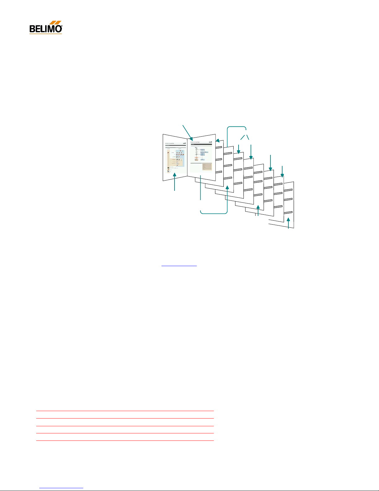
The documentation is structured by subject and provides the following detail information:
Please contact your local Belimo agent or representative for more information and the latest VAV documentation.
All Belimo product documentation (in pdf format) can be downloaded from
www.belimo.ch
Technical
data
Selecting a
syst em
kontrolle
atibilität
Tools
MFT
Bus
Klassisch
Funktionen
Tools
Compatibili ty
Setting up
Daten
Product
overview
Functions
Application
Classic Bus
Functional
testing
Overview
Contents 3 - 4
N-A Applications 5 - 20
N-E Expert 21 - 24
N-S Service 25 - 37
N-D Diagnosis 38 - 47
N-M Miscellaneous 48

3
4A1PC-T V2.1 NMV-D2M-EN 11-02-04.doc PM VAV - Subject to technical changes
VAV – Module NMV-D2M
Contents Designation N-...
Applications ______________________________________________________________ N-A
VAV-Compact NMV-D2M........................................................................................................N-A1
Customised versions..................................................................................N-A1.1
Support for..................................................................................................N-A1.2
Communication links to the NMV-D2M ...................................................................................N-A2
Local connection via diagnostic socket.....................................................N-A2.1
Direct connection to control cabinet or connection box............................N-A2.2
Connection in a bus system.......................................................................N-A2.3
Module NMV-D2M: General ...................................................................................................N-A3
Purpose....................................................................................................... N-A3.1
Description of the elements........................................................................N-A3.2
Operator interface N-A3.2.1
Description of the menu bar N-A3.2.2
Menu functions / Function keys N-A3.2.3
Description of the toolbar N-A3.2.4
Description of the buttons N-A3.2.5
‘Actuator symbol’ (data comparison) N-A3.2.6
Seal-bit function N-A3.2.7
Status line N-A3.2.8
Select required actuator (bus mode) N-A3.2.9
Basic functions..........................................................................................................................N-A4
Print <CTRL> <P>..................................................................................... N-A4.1
Addressing <F2>....................................................................................... N-A4.2
Address setting PP / MP N-A4.2.1
Methods of addressing N-A4.2.2
- by manual disengagement button N-A4.2.3
- according to serial number N-A4.2.4
Reset to OEM settin g <F5>.......................................................................N-A4.3
Log Data display <F3>............................................................................................................N-A5
Log data – Description of the elements..................................................... N-A5.1
Log file.........................................................................................................N-A5.2
Procedure N-A5.2.1
Access to previous months N-A5.2.2
File structure............................................................................................... N-A5.3
File name N-A5.3.1
Storage directory (path) N-A5.3.2
Trend recall <F6>....................................................................................................................N-A6
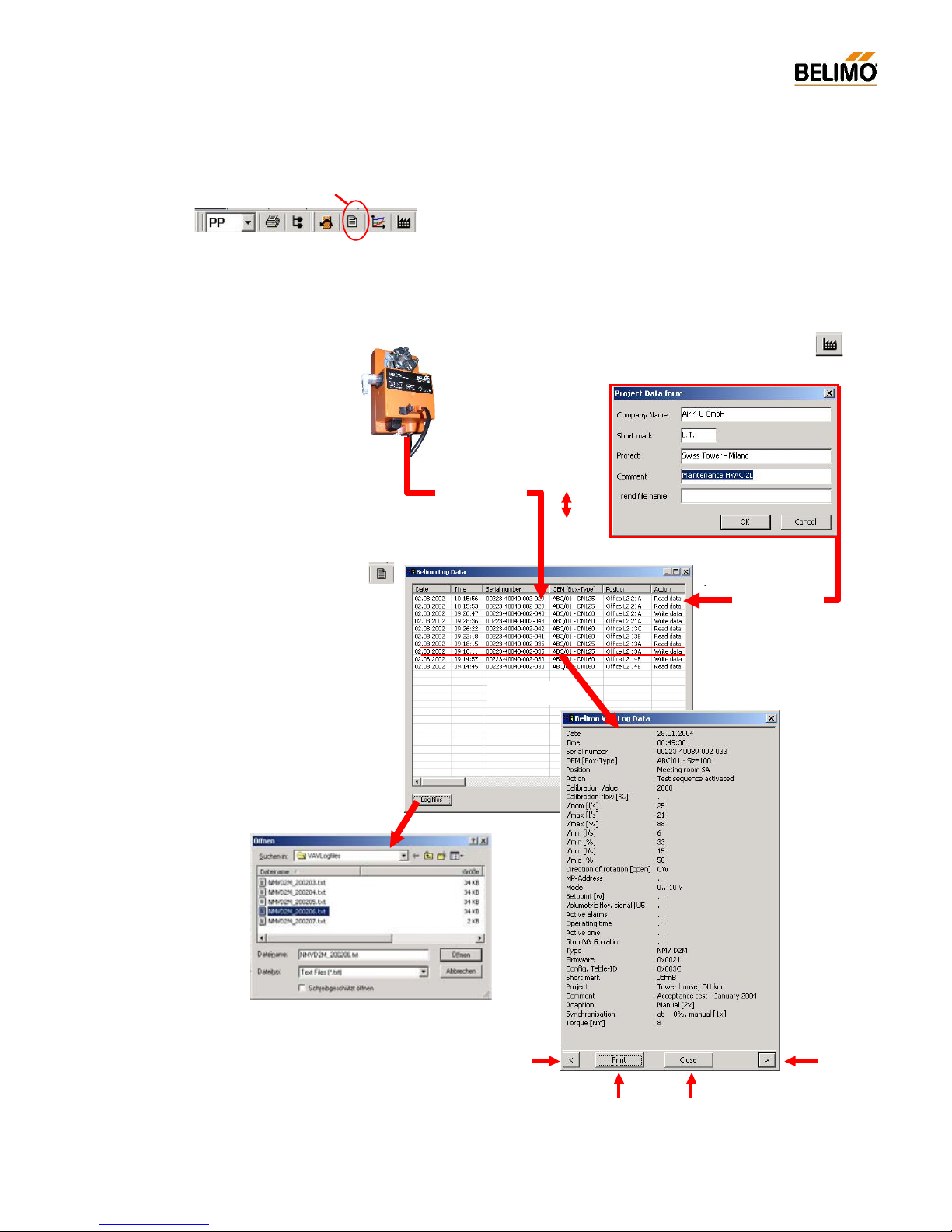
Project Data form <F4>...........................................................................................................N-A7
Data fields...................................................................................................N-A7.1
Procedure....................................................................................................N-A7.2
Extras ¦ Options ¦ NMV-D2M....................................................................................................N-A8
NMV-D2M password.................................................................................. N-A8.1
Flow unit......................................................................................................N-A8.2
Label printer................................................................................................N-A8.3
Box-Type – File selection...........................................................................N-A8.4
Log data - path selection............................................................................N-A8.5
Trend data - path selection........................................................................N-A8.6
Test-Sequence – File selection .................................................................N-A8.7
Help...........................................................................................................................................N-A9
Help entries................................................................................................. N-A9.1
About Belimo PC-Tool................................................................................ N-A9.2
Expert _ _________________________________________________________________ N-E
Using the ‘Expert’ register ........................................................................................................N-E1
Control Signal / Direction of rotation........................................................................................N-E2
Control signal.............................................................................................. N-E2.1
Reference signal (w) N-E2.1.1
Actual volumetric flow signal (U5) N-E2.12.
Sensor connection N-E2.1.3

4
4A1PC-T V2.1 NMV-D2M-EN 11-02-04.doc PM VAV - Subject to technical changes
VAV – Module NMV-D2M
Mode ........................................................................................................... N-E2.2
Direction of rotation, damper opening....................................................... N-E2.3
Actuator settings.......................................................................................................................N-E3
Adaption...................................................................................................... N-E3.1
Synchronisation .......................................................................................... N-E3.2
Torque......................................................................................................... N-E3.3
NMV-D2M versions data............................................................................ N-E3.4
Adaption....................................................................................................................................N-E4
Service___________________________________________________________________ N-S
Settings.....................................................................................................................................N-S1
V’nom.......................................................................................................... N-S1.1
Adjusting the operating value of volumetric flow...................................... N-S1.2
Position.......................................................................................................N-S1.3
NMV-D2M information ............................................................................................................. N-S2
OEM............................................................................................................ N-S2.1
Operating time............................................................................................ N-S2.2
Active time.................................................................................................. N-S2.3
Stop&Go ratio............................................................................................. N-S2.4
Calibration value......................................................................................... N-S2.5
Alarms ......................................................................................................... N-S2.6
Operation..................................................................................................................................N-S3
Enable ‘OPERATION’ ................................................................................ N-S3.1
Disable ‘OPERATION’ ............................................................................... N-S3.2
Status information....................................................................................... N-S3.3
Local override control.................................................................................N-S3.4
Operating steps.......................................................................................... N-S3.5
Reference / Actual value of damper position............................................ N-S3.6
Trend......................................................................................................................................... N-S4
Trend – Description of the elements ......................................................... N-S4.1
Live trend.................................................................................................... N-S4.2
Start/Stop N-S4.2.1
Selecting the operating step N-S4.2.2
Voltage readings in ‘Live Trend’ N-S4.2.3
Trend file ..................................................................................................... N-S4.3
File name N-S4.3.1
Storage directory (path) N-S4.3.2
Trend Recall <F6>.....................................................................................N-S4.4
Read Trend file N-S4.4.1
Test ...........................................................................................................................................N-S5
Test-Sequence ........................................................................................... N-S5.1
Start/Stop N-S5.1.1
‘Test’ – Diagnosis....................................................................................... N-S5.2
Status display – Step control ..................................................................... N-S5.3
Description of the elements....................................................................... N-S5.4
Selecting the operating step...................................................................... N-S5.5
Display of actual values ............................................................................. N-S5.6
Voltage display in ‘Live Trend’ N-S5.6.1
Selecting the Test-Sequence..................................................................... N-S5.7
Available Test-Sequences N-S5.7.1
Test log (Trend file).................................................................................... N-S5.8
File name N-S5.8.1
Storage directory (path) N-S5.8.2
Read Test log (Trend Recall <F6>)........................................................... N-S5.9
Diagnosis ________________________________________________________________ N-P
Index of recorded Test-Sequences.........................................................................................N-P1
Miscellaneous_____________________________________________________________ N-M
Function checks of the NMV-D2M...........................................................................................N-M1
‘Level 2’ function check.............................................................................. N-M1.1
‘Level 3’ function check.............................................................................. N-M1.2
Formulae................................................................................................................................... N-M2

5
4A1PC-T V2.1 NMV-D2M-EN 11-02-04.doc PM VAV - Subject to technical changes
VAV – Module NMV-D2M
N-A Applications
N-A 1 VAV-Compact NMV-D2M
The PC-Tool Module NMV-D2M has been d esigned specifically for the
VAV-Compact NMV-D2M and its use in connection with CAV and VAV air
boxes.
N-A1.1 Customised versions
Belimo VAV-Compact controllers are control devices that have been
manufactured for specific customers and are produced individually for
various air box manufacturers (OEMs). Therefore, each version is an optimum match for the components used by particular manufacturers, such
as measuring transducers, damper spindles and mounting systems.
Some customised versions have different operating step control systems
than the standard NMV-D2M. The technical documentation p rovided b y
the manufacturers of the air boxes should be given close attention.
N-A 1.2 Support for …
… VAV-Compact NMV-D2 / NMV-24V / NMV-24D
These device s are not sold any more and are not supported by PC-Tool
V2.
... VAV-Universal VRD2 / VRD2-L / VRP / VRP-STP
are not supported by PC-Tool V2.
... VAV ...24-MFT2 actuators
These actuator types need the MFT -PC Module of PC-Tool.
Therefore, please change over to the appropriate module.
... VAV ...24 V actuators
These types are pure VAV actuators from the VAV-Universal range and
are not supported by PC-Tool V2.
Designation of customised versions
NMV-D2M xxx
Customer designation
Basic product
Changing old Belimo VAV controllers
When planning to change old Belimo VAV controllers
such as VR1, VR2, NMV24-D and NMV24-V first get in
touch with your local Belimo agent or representative !

6
4A1PC-T V2.1 NMV-D2M-EN 11-02-04.doc PM VAV - Subject to technical changes
VAV – Module NMV-D2M
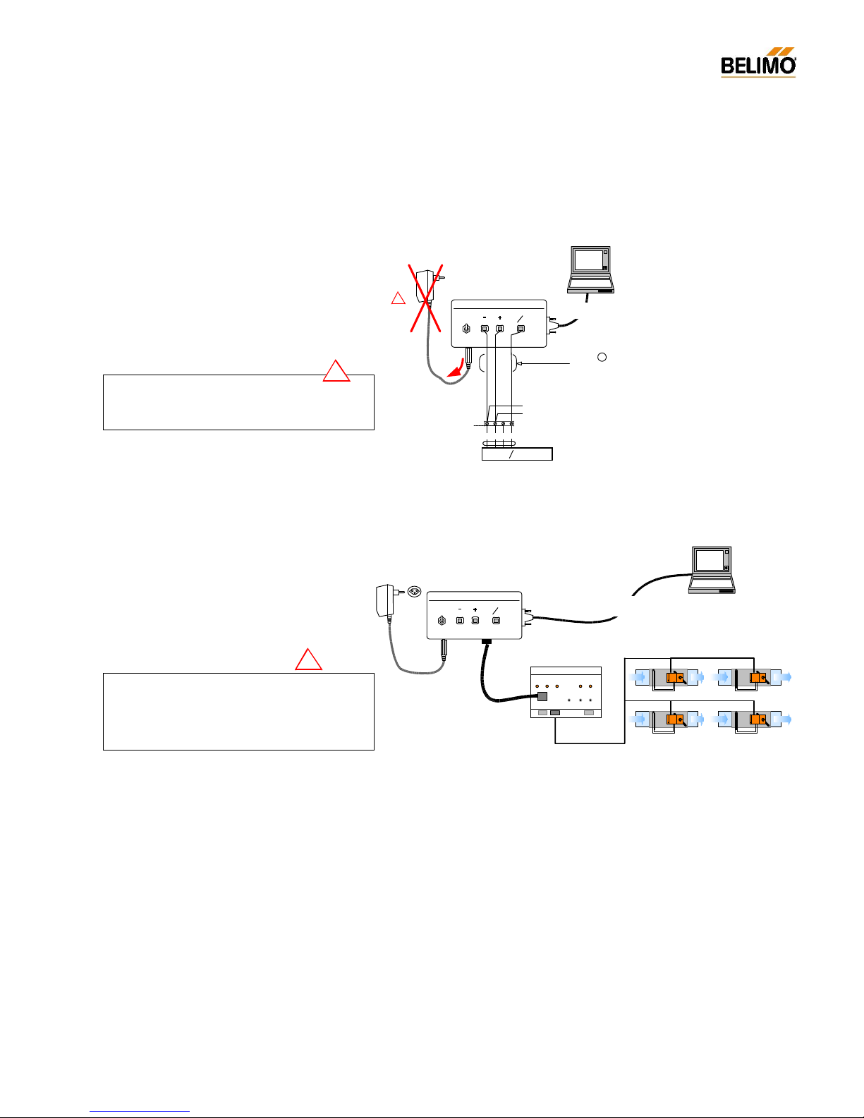
N-A2 Communication links to the NMV-D2M
The NMV-D2M c an be connected to a PC through a ZIP-RS232 or ZIP232-KA interface unit. There are various alternative types of cable (b and
c) available f rom the ZKS-VAV cable sets for making on-site connections
with the combination of the ZIP-RS232.
N-A2.1 Local connection via diagnostic socket
wsswrt
NMV-D2M powered from installation
AC 24 V
ZIP-RS232
1
2 5
OFF
Actuator
RS232
ON
U
PP
~
T
Beli mo
PC-Tool
Cable f rom
kit ZIP-RS232
NMV-D2M
AC 230 V
ZN230-24
Cable
from kit ZKS-VAV
b
!
Power supply AC/DC 24 V
Duplicated NMV-D2M power supply !
The NMV-
D2M must not have a duplicated power
supply! When using this method of connection re-
move the AC 24 V plug from the ZIP-RS232 unit.
!
NMV-D2M powered from installation
Belimo
PC-Tool
Cable RS232 1:1
D-Sub female-female
NMV-D2M
Kabel :
ZK1-VAV
Power supply AC/DC 24 V
Rx/ Tx
Enable
Power
ZIP -2 32- KA
ZIP- 232-KA
Detailed information about the MP-bus interface
- ZIP-232-KA
- ZIP-RS232
can be found in the data sheet ZIP-232-KA and ZIPRS232.
7
4A1PC-T V2.1 NMV-D2M-EN 11-02-04.doc PM VAV - Subject to technical changes
VAV – Module NMV-D2M
N-A2.2 Direct connection to control cabinet or
connection box
N-A2.3 Connection in a bus system
NMV-D2M powered from installation
wsswrt
AC 24 V
ZIP-RS232
1
2 5
OFF
Actuator
RS232
ON
U
PP
~
T
AC 230 V
ZN230-24
~
T
+
_
5321
NMV- D2 M
U
PP
w
~ T
+
_
AC/ DC 24 V
Belimo
PC-Tool
Cable from
kit ZIP-RS232
Cable
from kit ZKS-VAV
c
!
control cabinet or
connecti on box
NMV-D2M powered via bus cable
MP-Bus
Cable from
kit ZIP-RS232
Cable from
kit ZIP-RS232
Belimo
PC-Tool
MP ...
MP 8
-+
-+
MP 1
MP ...
-+
-+
AC 230 V
ZN230-24
AC 24 V
ZIP-RS232
1 2 5
OFF
Actu at or
RS232
ON
U
PP
~
T
UK24 LON
BELI MO
2
Connecting PC-Tool to the bus system !
In bus mode no tools may be operated through the
communications socket of the NMV-
D2M. For this
application the connection is made directly to the
UK24LON unit or the DDC system.
!
Duplicated NMV-D2M power supply !
The NMV-
D2M must not have a duplicated power
supply! When using this method of connection re-
move the AC 24 V plug from the ZIP-RS232 unit.
!
Detailed information about the MP-bus interface
ZIP-RS232 can be found in the da ta sheet ZIP-RS232.

8
4A1PC-T V2.1 NMV-D2M-EN 11-02-04.doc PM VAV - Subject to technical changes
VAV – Module NMV-D2M
N-A3 Module NMV-D2M: General
N-A3.1 Purpose
Module NMV-D2M is used specifically for VAV air bo xes to operate and
assign parameters to the Belimo VAV-Compact NMV-D2M controller. The
functions are shared between the two ‘Service’ and ‘Expert’ registers depending on the particular application.
In addition to these two registers the module also offers users a variety of
basic functions. This chapter describes each of those functions in detail.
N-A3.2 Description of the elements
N-A3.2.1 Operator interface
Menu bar
Toolbar
Actuator ident ifier
Active communication link
Status line
Buttons
Data comparisonRegister

9
4A1PC-T V2.1 NMV-D2M-EN 11-02-04.doc PM VAV - Subject to technical changes
VAV – Module NMV-D2M
N-A3.2.2 Description of the menu bar
N-A3.2.3 Menu functions / Function keys
Menu entry Brief description Function key
File
¦ Print… Controller settings of active <CTRL> <P>
¦ NMV-D2M are printed out
¦ Print to file… Controller settings of active <CTRL> <shift> <P>
¦ NMV-D2M are stored in a text file
¦ Printer setting… Printer option
¦ Windows function
¦ End Close program <ALT> <F4>
Menu entry Brief description Function key
Module
¦ MFT-PC Module for assigning parameters to Belimo MFT actuators,
¦ such as AM24-MFT, AF24-MFT, etc.
¦ NMV -D2M VAV module for VAV-Compact NMV-D2M controllers
Menu entry Brief description Function key
Extras
¦ Address actuators… F2 Change address assigned to NMV-D2M <F2>
¦ Options...
¦ General
¦ - Language Select program language
¦ - Com Port Set communication Port 1...4
¦ - Module release Activate special functions (only for manufacturers)
¦ MFT-PC
¦ - Actuator password Activate password function
¦ NMV-D2M
¦ -
NMV-D2M password Activate password function
¦ - Flow unit Display volumetric flow in m3/h / l/s / cfm
¦ - Label printer Activate label printer (only for manufacturers)
¦ - Box-Type Select Box-Type file (only for manufacturers)
¦ - Log data Select storage directory
¦ - Trend data Select storage directory
¦ - Test-Sequence Select Test-Sequence file
Menu entry Brief description Function key
NMV-D2M
¦ Reset to OEM setting Reset operating flow settings to <F5>
¦ OEM default values
¦ Log Data display Show log file <F3>
¦ Trend Recall Display stored trend data <F6>
¦ Project Data form Open input screen mask for project data <F4>
¦ for trend, log, test and print functions
¦ Select Test sequence… Browse option for the selection of <F7>
Test sequence
10
4A1PC-T V2.1 NMV-D2M-EN 11-02-04.doc PM VAV - Subject to technical changes
VAV – Module NMV-D2M
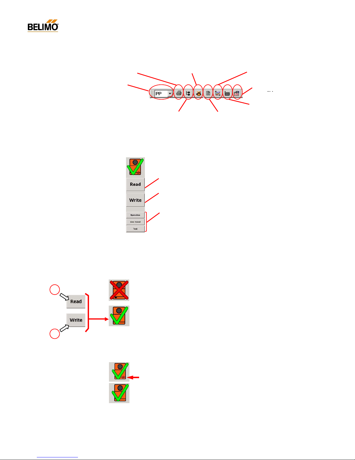
Screen data and NMV-D2M data do not agree:
a) Read data not executed
b) Screen data changed but Write data not e xecuted
Screen data and NMV-D2M data agree.
N-A3.2.4 Description of the toolbar
N-A2.3.5 Description of the buttons
The buttons are adapted to suit the various directories.
N-A3.2.6 ‘Actuator symbol’ (data comparison)
The large NMV-D2M symbol, above the buttons, shows the consistency
of data between the connected NMV-D2M and the scree n display.
N-A3.2.7 Seal-bit function
The settings of operating flow rate programmed by the manufacturer
V’min, V’mid and V’max are flagged by the so-called ‘seal bit’. If any of
these values are adjusted on-site it will be indicated by the ‘broken seal
bit’ symbol. The manufacturer’s value (OEM defaults) can be reset at any
time with the <F5> f unction‚ OEM defaults’. However, the seal bit cannot
be reset by the user.
When used in the MP-Bus system:
‘Select required actuator’
[MP1 ... 8]
Print parameters <CTRL> <P> Reset to OEM setting <F5> Trend Recall <F6>
Address NMV-
D2M <F2>
Display Log Data <F3>
Project Data form <F4>
Read:
Reading parameters from the connected NMV-D2M controller.
Write:
Writing changed parameters to the connected NMV-D2M controller.
Buttons:
See ‘Experts‘ and ‘Service‘ descriptions.
a
b
Select Test
sequence <F7>
11
4A1PC-T V2.1 NMV-D2M-EN 11-02-04.doc PM VAV - Subject to technical changes
VAV – Module NMV-D2M
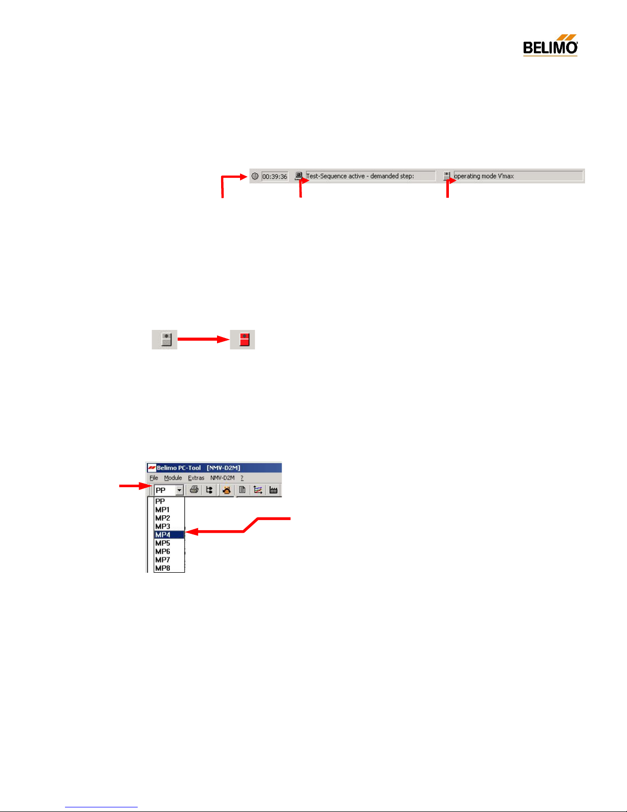
N-A3.2.8 Status line
The active program and the status of the NMV-D2M are indicated on this
line.
NMV-D2M Status indicator – red symbol
If the NMV-D2M cannot be overridden by the PC-Tool it will be indicated
by a red actuator symbol. The following states are indicated:
- Adaption active (triggered locally or via the PC-Tool)
- Synchronisation active
- Local override control active, e.g. CAV ‘Close’ step
N-A3.2.9 Select required actuator (bus mode)
Open address wind o w
Select required ad dress, e.g. MP4
The selected active communication link is shown in the actuator identifier.
Duration of link
hh:mm:ss
Program status
- Read data
- Write data
- Operation active
- Trend data recording active
- Test-Sequence – check system pressure
- Test-Sequence active – demanded step
- ...
NMV-D2M status
- Adaption / Synchronising active
- Motor s top
- Damper opening / closing
- V’m in / V’mid / V’max active
- operating mode V’nom
- Auto [reference input w]
- Variab le cont rol V’mi n... V’m ax
- Local override control active
- ...
Normal
No control function
possible
e.g.
synchronisation
active
12
4A1PC-T V2.1 NMV-D2M-EN 11-02-04.doc PM VAV - Subject to technical changes
VAV – Module NMV-D2M
N-A4 Basic functions
The basic functions described below are available in all directories.
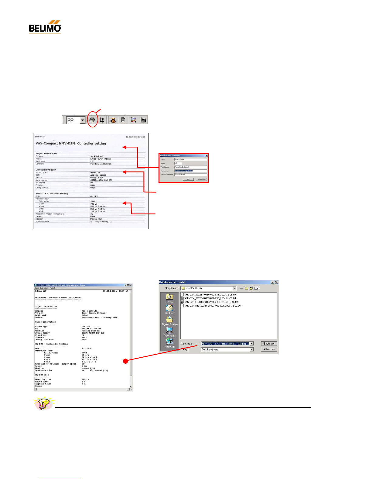
N-A4.1 Print controller date
N-A4.1.1 Print <CTRL> <P>
The following data and s ettings of the active NMV-D2M are printed:
- Project information <F4>
Project-specific information: this is not NMV-D2M data but entries from the ‘Acquire
project data’ inpu t screen mask.
Note: The data of the this screen mask remains
valid until the relevant fields are deleted or overwritten.
- Equipment information
Type / OEM info / Position / Serial number / MP address / Version designation
- NMV-D2M controller settings
Mod e / Oper atin g flow r ate se tti ng (c alibr atio n value / V ’no m / V’ max, V’ mid , V ’min)
/ Direction of rotation / Torque / Adaption an d synchronisation
N-A4.1.2 Print to file <Shift> <CTRL> <P>
The data from the connected NMV-D2M xxx gets stored in a text file:
The created text file name defaults to :
- layout: NMV-D2M_serialnumber_date.TXT
z.B.: NMV-D2M_00223-40039-002-033_2004-01-08.txt
Name and directory might be changed by demand.
Print <CNTRL> <P>
Practical tip – Project documentatio n
A fast a nd easy way to create the project documentation: save the data of the VAV controller to your PC’s hard disk by the use of the
‘Print to file’ feature and print or store them afterwards in your office.
13
4A1PC-T V2.1 NMV-D2M-EN 11-02-04.doc PM VAV - Subject to technical changes
VAV – Module NMV-D2M
Connect via safety
isolating transformer
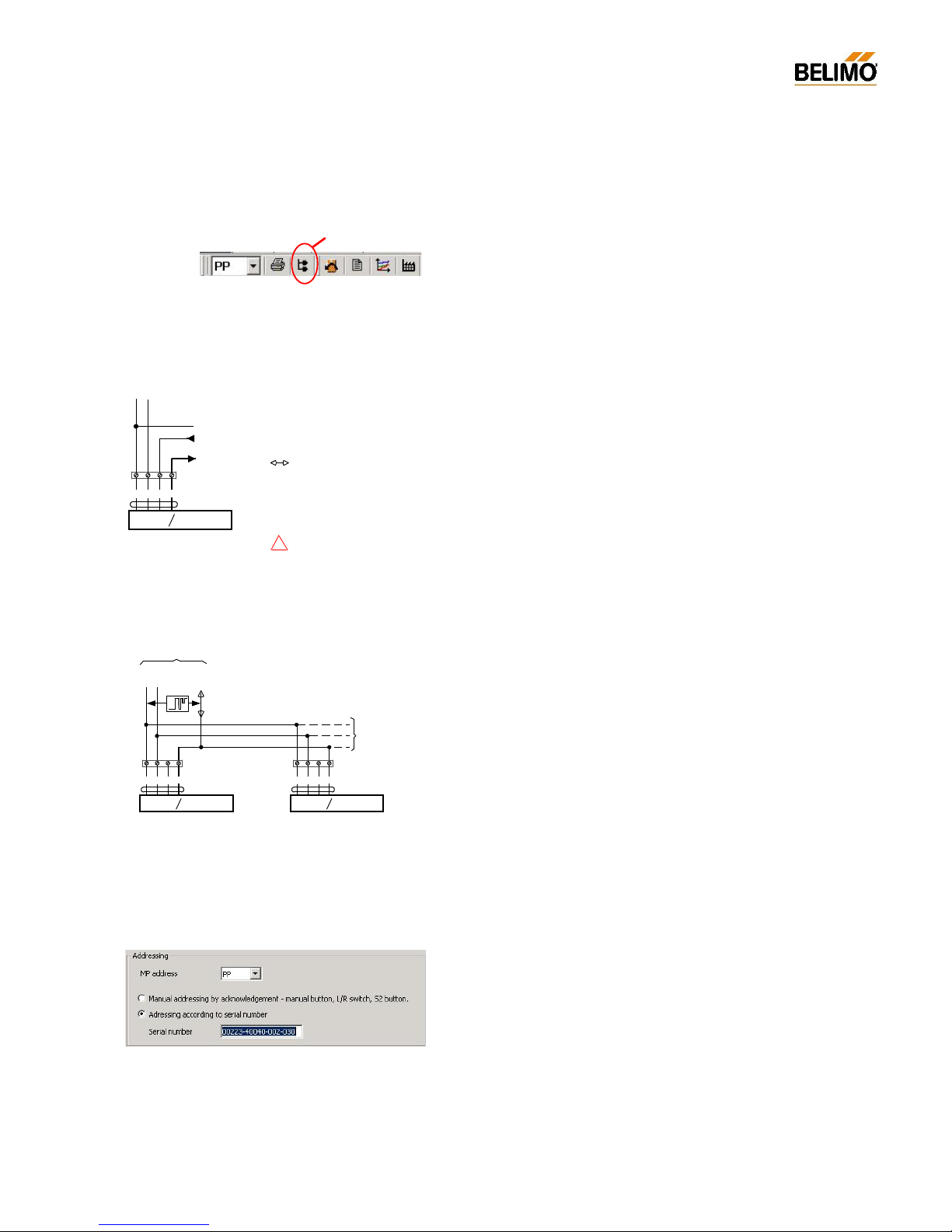
N-A4.2 Addressing <F2>
Conventional mode address: PP
When several NMV-D2M’s or MFT(2) actuators communicate over the
MP-Bus the y must be clearly identifiab le.
Bus mode address: MP1...MP8
N-A4.2.1 Address setting PP / MP
- Conventional mode setting ‘PP’ (Point-to-Point)
The ‘PP’ address is selected when an NMV-D2M under conventional control is connected to the PC-Tool.
See Connection diagram N-A2.1 and N-A2.2.
When an NMV-D2M is addressed ‘PP’ it is automatically assigned parameters for conventional mode.
For VAV, modulating control is ef fected with 0/2...10 V DC or, for CAV, by
means of step control. The signal for the actual value of volumetric flow
U5 is available at Terminal 5.
An NMV-D2M set for bus mode (MP) can be reset for conventional control
by addressing for ‘PP’.
- Bus mode setting ‘MP’ (Multi-Point)
Address ‘MP1...MP8’ is selected when several NMV-D2M’s or other Belimo MFT(2) actuators are incorporated into a higher level system via the
MP-Bus. In this case the connection is always made at the bus interface,
e.g. UK24LON and never directly to the communication socket of the
NMV-D2M. See Connection diagram N-A2.3.
If an NMV-D2M is given an MP address ‘MP1...MP8’ it will automatically
be assigned parameters for MP-Bus operation. I n this case control is effected digitally over the MP-Bus.
N-A4.2.2 Methods of addressing
The screen mask for addressing the NMV-D2M is called from the menu,
the toolbar or the <F2> function key.
There are two methods available:
- Addressing by manual disengagement push-button
- Addressing according to serial number
MP
~
T
+
_
AC 24 V
DC 24 V
5321
NMV-D2M
U
MP
w
~ T
+
_
5321
NMV-D2M
U
MP
w
~ T
+
_
Further
NMV-D2M or
MFT2 actuators
UKK24LON
or
DDC with MP-Bus interface
5321
NMV-D2M
U
MP
w
~ T
+
_
Reference valu e inp ut w
Actual vol umetric flow signal U
5
PP-Communication Tool
T
AC 24 V
~
T
DC 24 V
+
_
Addressing <F2>
!
14
4A1PC-T V2.1 NMV-D2M-EN 11-02-04.doc PM VAV - Subject to technical changes
VAV – Module NMV-D2M
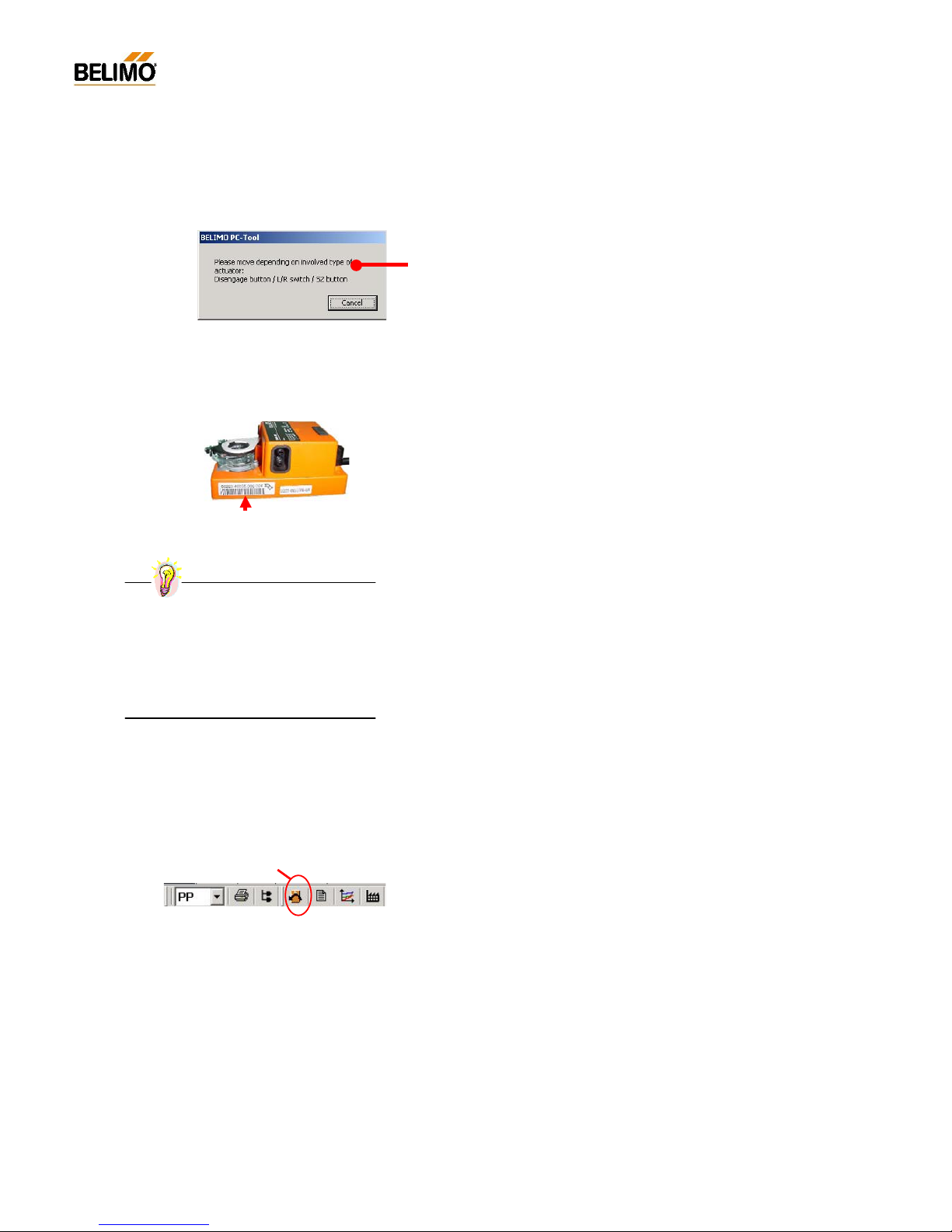
N-A4.2.3 Addressing by manual disengagement push-button
Procedure:
- Set the required address in the ‘MP address’ field.
- Activate ‘Manual addressing by acknowledgement’
- Press ‘OK’
- Press the manual disengagement push-button on the NMV-D2M. An
appropriate signal is given if the setting of the address is successful.
Repeat the procedure if a fault alarm is given.
N-A4.2.4 Addressing according to serial number
Procedure:
- Set the required address in the ‘MP address’ field.
- Activate ‘Addressing according to serial number’
- Enter the serial number (by hand or bar code reader)
When there is a direct link to the actuator the serial number read from
the NMV-D2M appears as the default value.
- Press ‘OK’
- An appropriate signal is given if the setting of the address is successful.
Repeat the procedure if a fault alarm is given.
N-A4.3 Reset to OEM setting <F5>
This f unction allows changed settings of operating volumetric flow to be
reset to the unit m anufacturer’s def ault values.
The following values are reset:
V’max
V’mid
V’min
Reset to OEM setting <F5>
Practical tip – Address stick er
Detach the large sticker and paste it on to the
appropriate installation plan.
This will allow addressing to be carried out
later with no need for direct access to the
controller. It also forms part of the installa
tion’ s
documentation.
15
4A1PC-T V2.1 NMV-D2M-EN 11-02-04.doc PM VAV - Subject to technical changes
VAV – Module NMV-D2M
N-A5 Log Data display <F3>
Each read and write function is recorded in the NMV-D2M module in a
monthly log file. User actions and controller settings that have been executed from the appropriate PC can be displayed on the PC-Tool, and be
printed out if necessary, wit hout an acti ve connection to the NMV-D2M.
N-A5.1 Log data – Description of the elements
Log Data display <F3>
Access to previous
months
New entries
NMV-D2M
Print zoom
Project data form / <F4> /
Close zoom
Controller data
- Identification
- Setting
- Version ID
Read /
Write
Zoom d isplay
Log Data display / <F3> /
Project data
- Project
- File name
- Comment
Old entries
 Loading...