

Page 1
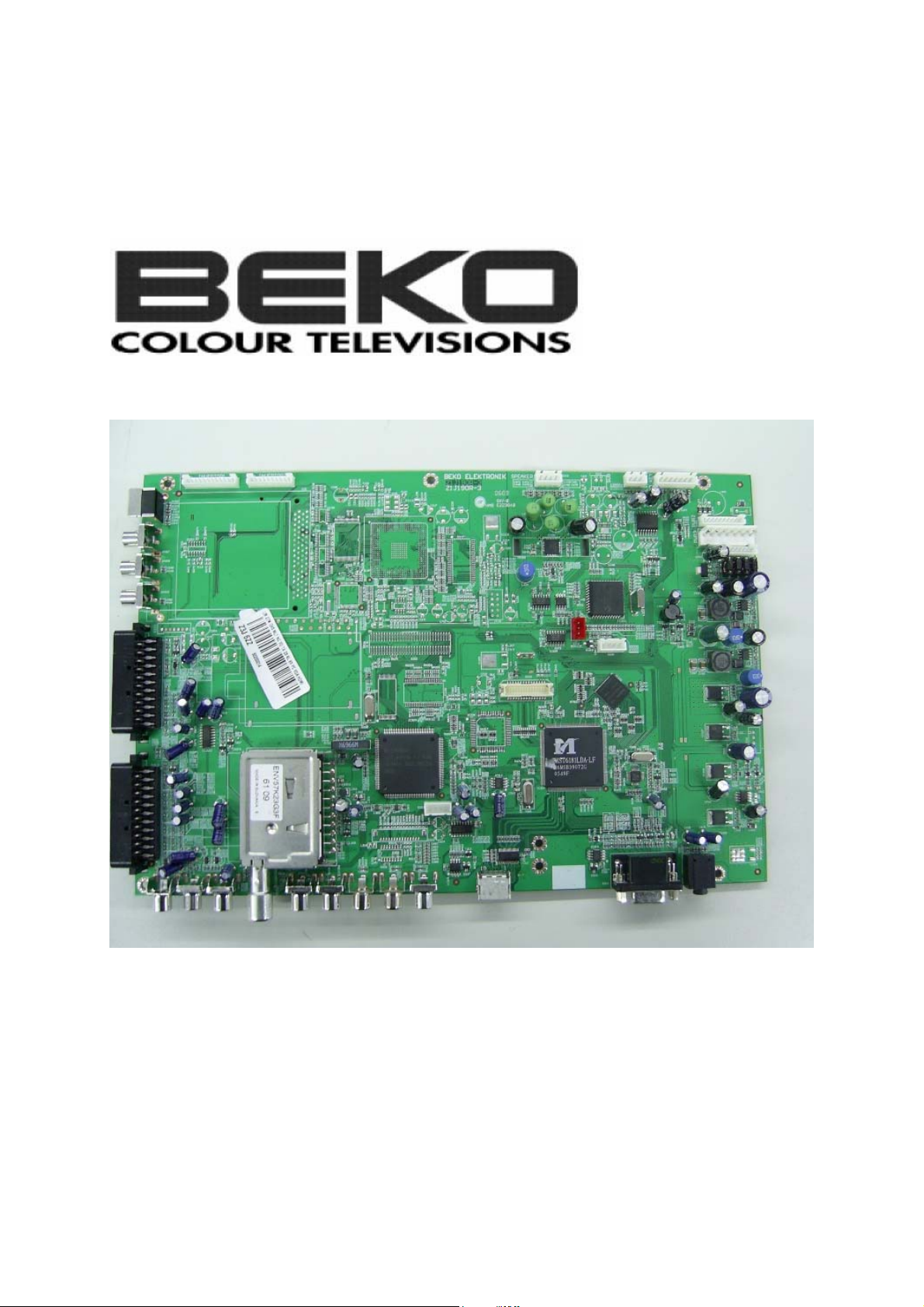
SERVICE MANUAL
LM CHASSIS
Page 2

CONTENTS PAGE
Safety Instructions 3
Technical Specifications 4
Features 5
Inputs/Outputs Diagram 6
Remote Control 7
Set Apperance 8
Service Adjustments 9
Block Diagram 12
Power Supply Diagram 13
Data Sheet VCT4993 14
Data Sheet MST6181 16
Data Sheet MTV512 24
Data Sheet TVP5150A 26
Parts List 32
Circuit Diagram Attached
Page 3

SAFETY PRECAUTIONS
GENERAL GUIDELINES
1. Always use the manufacturer’s replacement safety
components. The critical safety components marked
with on the schematics diagrams should not be
by other substitutes. Other substitute may create the
electrical shock , fire or other hazards. Take
attention to replace the spacers with the originals.
Furthermore where a short circuit has occurred ,
replace those components that indicate evidence of
overheating.
2. After servicing , see that all the protective devices
such as insulation barriers, insulation papers, shields
and isolation R-C combinations are correctly
installed.
3. When the receiver is not being used for a long time
of period of time , unplug the power cord of the
Adaptor from the AC outlet.
Color TFT LCD Module is very sensitive
both electrically and physically.Users,
therefore, are requested to follow the
“Guidance of handling color TFT LCD
Module”on the followings.
1 - Be careful not to make scratch on the
polarizer.
Surface of polarizer is soft and can be physically
damaged easily.
Please do not touch, push or rub polarizer surface
with materials over HB hardness.
2 - Keep clean the surface.
Please wear rubber glove when touch the surface of
LCD screen. Please use so ft and anti-static material
as cleaner.
3 - Keep out of water.
Water on/in the LCD may cause electrical short or
corrosion. Please wipe out dry or water carefully.
4 - Prevent swift Temperature &
Humidity change.
Instantaneous temperature and/or humidity change
can make dew or ice which cause nonconformance
such as malfunction.
5 High temperature & high humidity
reduce the life-time.
LCD is not proper to be used at high temperature
and high humidity. Please keep specified
temperature and humidity condition.
6 - Keep out of Corrosive Gas.
Corrosive gas effect the polarizer and the circuit
chemically and cause defects accordingly.
7 - Electrostatic discharge can make
Damage
There are electro-static sensitive components such
as CMOS in LCD Module. Please earth human
body when handle the LCD.In addition, please do
not touch the interface connector pin with bare.
8 - Do not operate for a long time under
the same pattern
Operating LCD for a long time under the same
pattern can cause image persistence and can
damage it. Please follow following guidance.
1. Turn the power off when do not use.
2. Change the pattern periodically.
Page 4

Technical specifications chart
Picture tube
size/type
Sound outlet
power (10% THD)
Power
consumption
Stand-by Power
consumption
27” 16:9
active matrix TFT
2x7 W
120 W
1 W
General technical specifications
Power supply
AC: ............................................................................
Program memory: ...................................................100
RF Antenna input: ...................................................75 Ohm (Co-axial)
Loudspeaker impedance: ......................................4 Ohm
Sound systems:.......................................................Mono/Stereo/Nicam
Batteries:..................................................................2xUM - 4, IEC R03 or AAA 1.5V
Received channels:.................................................VHF (Band I channel 2-4)
..................................................................................VHF (Band III channel 5-12)
..................................................................................UHF (Channel 21-69)
..................................................................................Cable TV (S1-S20/S21-S41)
Received broadcasting systems............................PAL B G
230V~50 Hz
PAL SECAM BG
PAL SECAM BG DK/DK’
PAL SECAM BG LL’
PAL I
Note: Your television has been manufactured in accordance with your country by selecting from
among the above mentioned broadcasting systems and this system cannot be changed by the user
except the case described below: In countries where BG/DK and BG/LL’ broadcasts are done (BG
or DK / BG and LL’). For further information, see the settings part about your television.
4
Page 5

Your Television
Features
• 27” TFT-LCD WXGA Panel
• Available for cable broadcasts
• 2x7 W Stereo sound
• 12 pages of teletext Feature
• PIP (Picture in Picture) Feature from AV
• Wide angle of vision
• Scart socket, AV Socket and external sound system connection
• S-VHS and Cinch inputs for S-Video connection
• PC connection
• Low energy consumption
•AVL
•ATS
• Programmable power off
• Graphic equalizer
• The feature of sharpness in Colour Transitions (CTI)
• Sharpness feature and picture resolution (LTI) in the black-white transitions
• A clear Picture made possible by the Digital Comb Filter
• On screen viewing of all settings, program numbers and all the processes
• Manual Fine Tuning
• 100 Program memory
• Infrared Remote Control equipped all the functions
• Child Lock
• Feature of viewing the NTSC broadcast to be entered via Scart
Easy performance of the processes via the advanced menu system. Ability to choose 26 different
menu languages.
• HDMI feature
5
Page 6
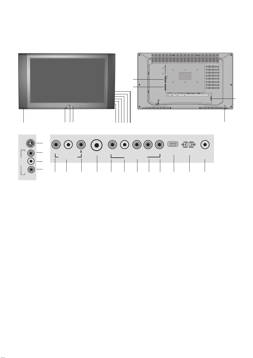
S-VHS
AV-3
12
11
SCART1SCART 2RLV
AUDIO
DVI-D
LRYPbPr
HDMI
PC-
R
LV
ANT IN
COMPONENT
AV-OUT
VIDEO INPUT
PC-DVI
IN
AUDIO-IN
13
10
AV3
S-VHS
V L R
15
16
17
18
123
SPDIF L
AUDIO-OUT
20 22 25 28 29 3019 21 23 24 26 27
1. Standby status indicator
2. Network power on/off button
3. Remote control receiver
4. Volume turn-down button
5. Volume enhancement button
6. Menu Button
7. Source selection
8. Program decrease button
9. Program increase button
10. Speaker
11. Scart 1
12. Scart 2
13. Power supply input
14. Headphones output
15. S-VHS connector
ANT IN
4
567 8 9
AUDIO
L PC-INR Y Pb Pr
COMPONENT
VIDEO INPUT
HDMI
16. Video input CINCH connector
17. Sound input CINCH connector (Left/L)
18. Sound input CINCH connector (Right/R)
19. SPDIF Digital audio output
20. Sound output (Left/L)
21. Sound output (Right/R)
22. Antenna input
23. Component sound input (L)
24. Component sound input (R)
25. Component video input (Y)
26. Component video input (Pb)
27. Component video input (Pr)
28. HDMI
29. VGA (PC connection input)
30. PC sound input
PC
AUDIO-IN
14
Note:
• Please do not use the video RCA and S-Video connection simultaneously, in that case, these
two devices might influence the picture quality of one another.
• RGB offers the best picture quality over the Scart.
6
Page 7
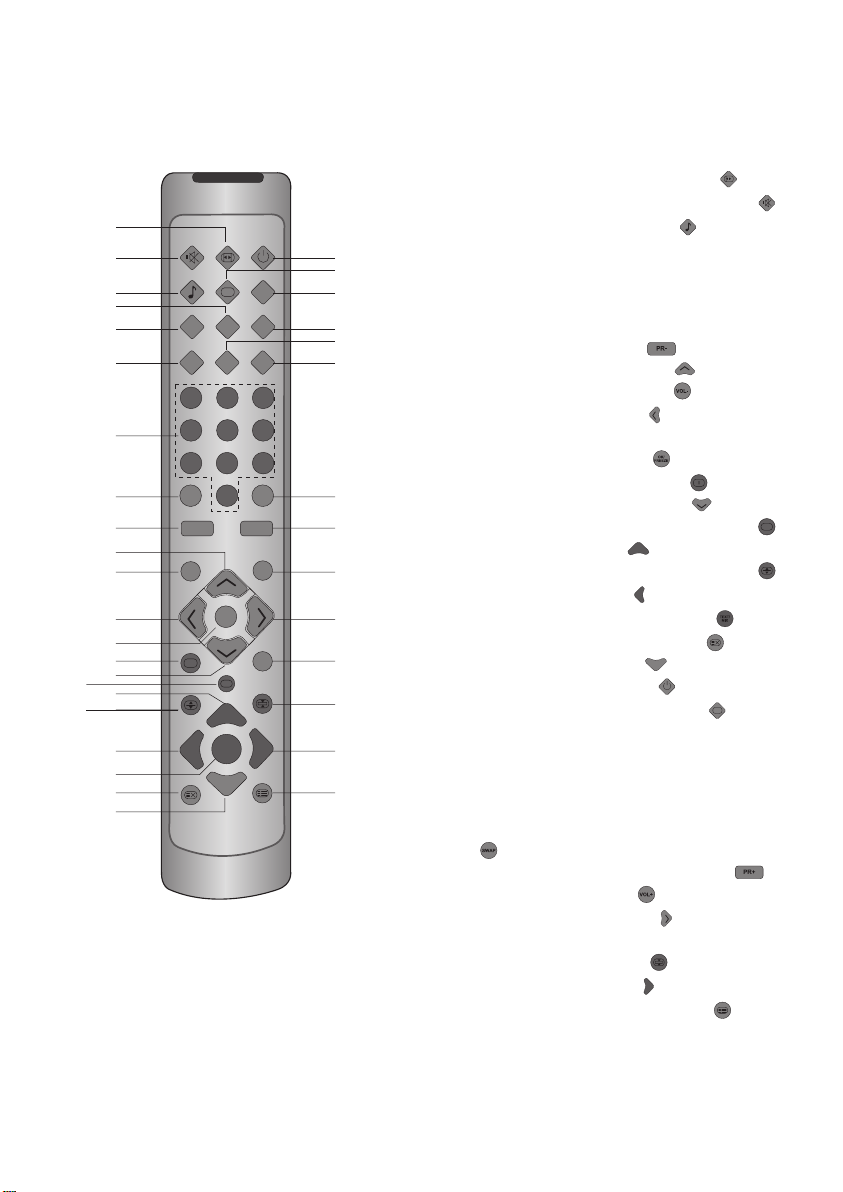
Remote Control
1
2
3
4
5
6
7
8
9
10
11
12
13
14
15
16
17
18
19
20
21
22
PIP SEL.
AV
123
456
789
ZOOM
PR- PR+
VOL-
i
PIP POS.
PC
0
OK/
FREEZE
TEXT/
MIX
1. Picture Format selection button ( )
PAT
PIP SIZE
TV
2. Temporary sound mute (Mute) button (
3. Equalizer selection button (
23
24
25
26
27
28
4. PIP Position selection button
5. PIP/PAP On-Off button
6. AV modes selection menu button
7. Numeric buttons
8. ZOOM mode selection button
9. Program down button (
10. Upward movement button(
11. Volume turn-down button (
12. Left movement button (
)
)
) (Menus)
)
) (Menu)
)
13. Confirmation(OK) and Temporary picture
freeze button (Freeze) ( )
SWAP
29
30
14. Info / Txt index page button (
15. Downward movement button (
16. Txt Question/Answer button (Reveal) (
17. Red teletext button (
VOL+
MENU
?
31
32
33
34
35
18. Teletext page enlarge button (Double) (
19. Blue Teletext button (
)
20. Teletext / Mix selection buttons (
21. UPDATE Button/Teletext time (
22. Yellow teletext button (
23. Stand-by On/Off button (
24. Picture Mode selection button (
25. PAT (Picture and Teletext) Mode
Power On-Off button
)
) (Menus)
)
)
)
)
)
)
)
)
26. PIP size selection button
36
27. PC mode access button
28. PC mode access button
29. Final program selection button (SWAP)
)
(
30. Program forward selection button (
31. Audio turn up button (
32. Right movement button (
)
) (Menus)
)
33. MENU button
34. Txt Stop button (Hold) ( )
35. Green teletext button (
36. Sub page button (SUB PAGE) (
)
)
7
Page 8
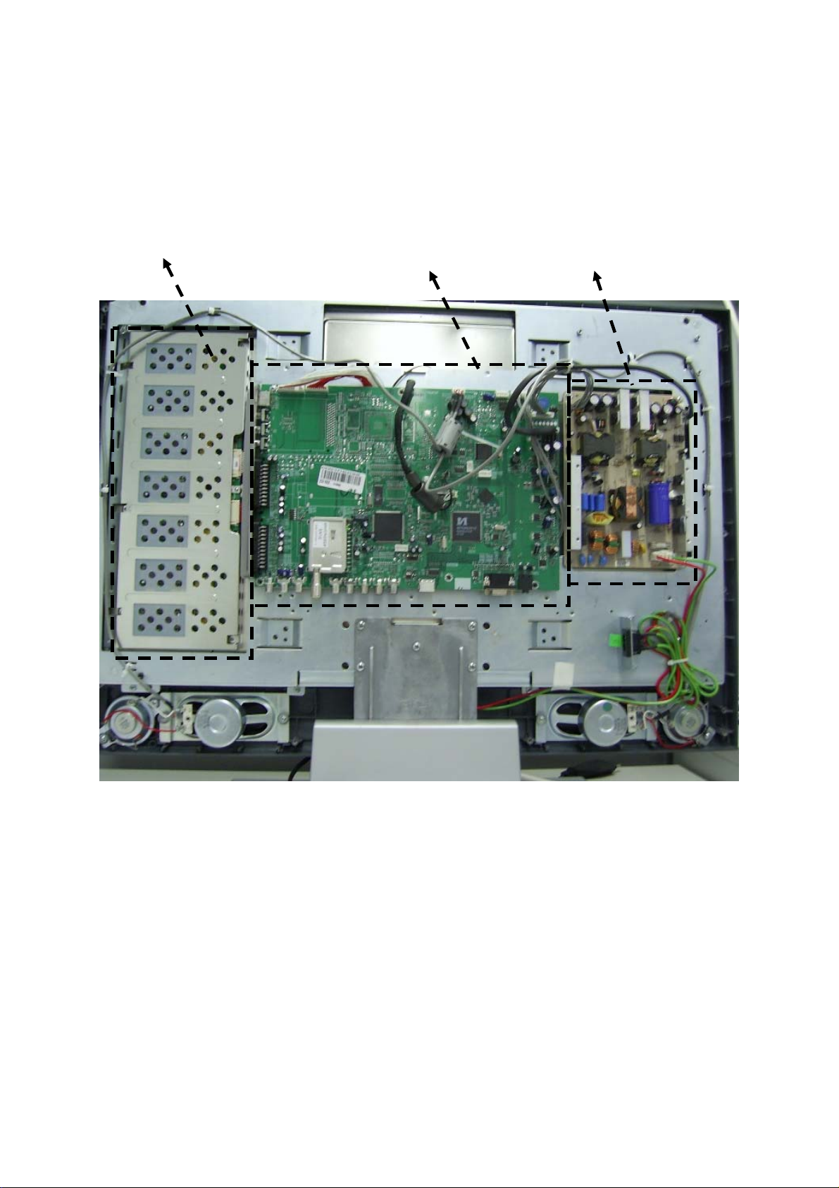
SET APPERANCE
INVERTOR(BUILT IN PANEL) MAIN CHASSIS POWER SUPPLY BOARD
8
Page 9

LM SERVICE MODE
1. Activating the Service Menu
When the menu is on the screen press ‘9’, ‘3’, ’0’, ’1’ on the remote controller. This will activate
the service menu.
2. Service Mode Options
There are 6 submenus in this mode:
OPTIONS0, OPTIONS1, SOUND OPTIONS,IF SETTINGS, DIMMING, ADJUSTMENTS
2.1 OPTIONS0
STANDBY CUSTOME (Customer), FACTORY
TEXT Teletext Type : FAST (Fasttext), FAST TOP (Fastext and Toptext)
TEXT TBL AUTO : Selects the table according to the selected menu language
WEST: English-French-German-Turkish-Spanish-Italian-Finnish-Swedish
Norwegian, Danish
EAST : Polish-French-Hungarian-Czech-German-Sovenian-Italian-Romanian
GREE : WEST + Greek
CYRL : English-Russian-German-Czech-Estonian-Ukrainian-Letvian
ARAB : West + Arabian
FARS : West + Persian
HEBR : West + Hebrew
LANGUAGE A: English-German-French-Italian-Spanish-Portuguese-Greek-Turkish-Dutch-Swedish-
Danish-Norwegian-Finnish-Slovenian-Polish-Hungarian-Russian-Hebrew-RomanianCroatian-Czech-Slovak-Albanian-Bulgarian- Macedonian-Serbian
B: English-German-French-Italian-Spanish-Portuguese-Greek-Turkish-Dutch-Swedish-
Danish-Norwegian-Finnish-Slovenian-Polish-Hungarian-Russian-Romanian-CroatianCzech-Slovak-Albanian-Bulgarian- Macedonian-Arabic-Persian
PANEL Selects the software according to the panel name :
26 AU5, 32 AU3, 26 SS2, 32 SS3, 27 CH5, 32 CH2, 26 LP6,37 LP2, 26
QD2, 32 QD2
PIP NO (PIP via AV is not on), AV (PIP via AV is on)
PLUG PLAY ON (Demo mode), OFF
2.2 OPTIONS1
BLUEBACK ON, OFF
CTI Colour Transient Improvemnet Feature : ON, OFF, MENU
DNR Digital Noise Reduction : ON, OFF, MENU (selection via User Menu)
PROTECTION ON, OFF
PANORAMA AVAIL (On), NAVAIL (Off)
RC UNIT Remote Control Type: 43 Key, 45 key
PAT Picture and Text feature: AVAIL (On, Default), NAVAIL (Off)
HOTEL Simple Hotel TV feature: AVAIL (On), NAVAIL (Off)
HOTEL VOL Maximum sound level for Hotel Mode
9
Page 10

2.3 SOUND OPTIONS
BG EUROPE, NEWZ (New Zelland) AUST (Australia), NAVAIL (no BG)
DK AVAIL, NAVAIL
L/L AVAIL, NAVAIL
DOLBY AVAIL, NAVAIL
BASS OPT NONE (bass is not activated), DYN (Dinamic bass is activated),
SUBW (Subwoofer feature is on)
HEADPHONE AVAIL, NAVAIL
CARRI MUTE MSP (for all markets except Turkey), MICRO (for Turkey)
2.4 IF SETTINGS
TUNER PS DA5, THOMSON, TEMIC, PS D44, ALPS, PHILIPS
VHF III UHF AGC adjustment is 5 for this frequancy band
VHF I AGC adjustment is 5 for this frequancy band
AGC Method AGC adjustment method: FIXED, SYNC&PW, SYNC, S&PW&PD (Default)
SECAM MTD Secam decoding method : OLD, NEW (default)
2.5 DIMMING
No adjustment will be made in this menu for service purposes. Default value is 0.
2.6 ADJUSTMENTS
No adjustment will be made in this menu for service purposes. Default values are given below:
VCTI BLE BLE MODE 3
BLE GAIN 2
BLE TILT 8
BLE STATIC 7
FAC LTI LTI CORING 0
LTI GAIN 0
SLL SUCARR SLLTHDV 6
SUBCARIIER 19
LUMA DELAY DLY PAL 7
DLY SECAM 10
DLY NTSC 9
SCART RGB BRI -14
CONT 47
CB SAT 50
CR SAT 50
TINT 0
RGAIN 34
GGAIN 33
BGAIN 35
10
Page 11

MSTAR 6CR 5
6CG 5
6CB 8
6CC 0
6CM 3
6CY 2
6CF 5
SPECTRUM 1
ADJUST R GAIN 122
G GAIN 128
B GAIN 90
R OFFSET 125
G OFFSET 125
B OFFSET 126
SUBCON 58
SUB BRI 42
2.7 EEPROM EDIT
No adjustment will be made in this menu for service purposes.
11
Page 12
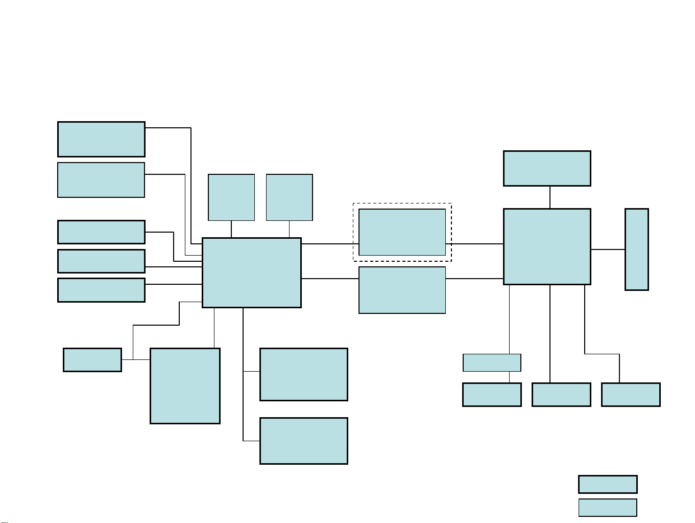
Chassis LM Block Diagram
Analog Tuner1
TU300
Analog Tuner2
TU302
IC329
Flash
IC335
128MB DDR
IC328
TxtRAM
Scart1
Scart2
SVHS
IR&Key
I2C
IC311
MTV512
Monitor
Controller
IC324
VCTi4993G
MAX9704
Audio Amp.
TDA7059
Headph. Amp
IC321
IC338
IC336
FRC 94XXA
IC309
TVP150
Video Decoder
IC301
HDMI
IC334
MST6181
VGA YPrPb
Optional
LVDS
Basic
Page 13

Power Supply Diagram
+12V
+3V3
T300
5V or 12V for LCD Panel
3V3 MST6181
VCTi
MST3383
2V5 DRAM
MST3383
MST6181
1V8 VCTi
MST6181
1V8 FRC
Only for FRC
12V Audio
T300 5V VCTi, Tuner
8V VCTi, Switches
IC300
IC302
IC337
IC306
IC305
IC308
IC307
13
Page 14

VCT 49xyI, VCT 48xyI ADVANCE INFORMATION
Volume 1: General Description
General Description
Release Note: This data sheet describes functions
and characteristics of the VCT 49xyI, VCT 48xyI
version F1.
1. Introduction
The VCT 49xyI, VCT 48xyI is an IC family of high-quality single-chip TV processors. Modular design and
deep-submicron technology allow the economic integration of features in all classes of single-scan TV
sets. The VCT 49xyI, VCT 48xyI family is based on
functional blocks contained and approved in existing
products like DRX 396xA, MSP 34x5G, VSP 94x7B,
DDP 3315C, and SDA 55xx.
Each member of the family contains the entire IF,
audio, video, d isplay, and deflection processing for 4:3
and 16:9 50/60-Hz mono and stereo TV sets. The integrated microcontroller is supported by a powerful OSD
generator with integrated Teletext & CC acquisition
including on-chip page memory.
Video & Sound IF
DRX 396xA
Audio Processing
MSP 34x5G
– Submicron CMOS technology
– Low-power standby mode
– Single 20.25 MHz reference crystal
– 8-bit 8051 instruction set compatible CPU
– Up to 256 kB on-chip program ROM
– WST,PDC,VPS,andWSSacquisition
– ClosedCaptionandV-chipacquisition
– Up to 10 pages on-chip teletext memory
– Multi-standard QSS IF processing with single SAW
– FM Radio and RDS with standard TV tuner
– TV-sound demodulation:
• all A2 standards
• all NICAM standards
• BTSC/SAP with MNR (DBX optional)
•EIA-J
– Baseband sound processing for loudspeaker chan-
nel:
• volume and balance
• bass/treble or equalizer
• loudness and spatial effect (e.g. pseudo stereo)
• Micronas AROUND (virtual Dolby optional)
• Micronas BASS and Subwoofer output
• further optional and licence requiring sound
enhancements as BBE, SRS Wow and Micronas
VOICE
– CVBS, S-VHS, YC
and RGB inputs
bCr
– ITU656 input
Video Processing
VSP 94x7B
Display & Deflection
DDP 3315C
Control, OSD, Text
SDA 55xx
VCT 49xyI
VCT 48xyI
Fig. 1–1: Single-chip VCT 49xyI, VCT 48xyI
1.1. Features
The VCT 49xyI, VCT 48xyI family offers a rich feature
set, covering the whole range of state-of-the-art 50/
60 Hz TV applications.
– PSSDIP88-1 package
– PMQFP144-2 package
– 4H adaptive comb filter (PAL/NTSC)
– multi-standard color decoder (PAL/NTSC/SECAM)
– Macrovision Detection
– Nonlinear horizontal scaling “panorama vision”
– Luma and chroma transient improvement (LTI, CTI)
– Non-linear color space enhancement (NCE)
– Dynamic black level expander (BLE)
– Selective Color Enhancer (SCE)
– 8/10 bit ITU656 output
– Scan velocity modulation output
– Soft start/stop of H-drive
– Vertical angle and bow correction
– Average and peak beam current limiter
– Nonlinear and dynamic EHT compensation
– Black switch off procedure (BSO)
14
Page 15

VCT 49xyI, VCT 48xyI ADVANCE INFORMATION
Volume 1: General Description
1.2. Chip Architecture
R
E
K
T
C
G
F
I
A
T
S
N
I
A
W
A
U
B
E
O
U
P
S
A
S
IFIN+
IFIN-
CVBS in
YCbCr in
RGB in
CVBS out
656 in
IF
Frontend
Video
Frontend
Slicer
24kB
Char ROM
20kB XRAM
IF
Processor
Comb
Filter
Component
Bus
Arbiter
256kB
Prog ROM
Interface
Sound
Demodulator
Color
Decoder
Display
Generator
CPU
8051
Memory
Interface
ADB, DB, PSENQ,
PSWEQ, WRQ, RDQ
Panorama
Scaler
Audio
Processor
I2C Master/
Slave
Timer
CRT
PWM
ADC
UART
Watchdog
RTC
I/O-Ports
Pxy
Display &
Deflection
Processor
Video
Backend
Reset & Test
Logic
Clock
Generator
656 out
PROT
HOUT
HFLB
VERT
EW
SVM
RGB out
RGB in
SENSE
RSW
I2C
RESETQ
TEST
XTAL1
XTAL2
Fig. 1–2: Block diagram of the VCT 49xyI, VCT 48xyI
15
Page 16

FEATURES
MST6181LDA
SXGA/WXGA LCD Multi-Function Monitor Controller with Dual LVDS Transmitter
Product Brief Version 1.0
Ÿ Input supports up to UXGA & 1080P
Ÿ Panel supports up to SXGA/WXGA
Ÿ Integrated 8-bit triple-ADC/PLL
Ÿ Integrated DVI/HDCP/HDMI compliant receiver
Ÿ RGB/YUV 444 and YUV422 digital video input
ports
Ÿ Dual high-quality scaling engines
Ÿ Built-in 3-D video de-interlacer
Ÿ Video-over-graphic PIP
Ÿ Video-by-graphic split screen
Ÿ MStarACE-2 picture/color processing engine
Ÿ Embedded On-screen display controller (OSD)
engine
Ÿ Digital audio I/O & sync processor
Ÿ Built-in dual-link LVDS transmitter
Ÿ 5 Volt tolerant inputs
Ÿ Low EMI and power saving features
Ÿ Supports PWM & GPO controls
Ÿ 256-pin LQFP
n Analog RGB Compliant Input Ports
Ÿ Dual analog ports support up to 165Mhz
Ÿ Supports PC RGB input up to UXGA@60Hz
Ÿ Supports HDTV RGB/YPbPr/YCbCr up to 1080P
Ÿ On-chip high-performance PLLs
Ÿ Supports Composite Sync and SOG
(Sync-on-Green) separator
Ÿ Automatic color calibration
n DVI/HDCP/HDMI Compliant Input Port
Ÿ Operates up to 165 MHz (up to UXGA @60Hz)
Ÿ Single link on-chip DVI 1.0 compliant receiver
Ÿ High-bandwidth Digital Content Protection
(HDCP) 1.1 compliant receiver
Ÿ High Definition Multimedia Interface (HDMI)
1.0 compliant receiver with I2S and S/PDIF
digital audio outputs
Ÿ Long-cable tolerant robust receiving
n Video Input Port
Ÿ One RGB/YUV 4:4:4 24-bit and one 4:2:2
ITU-R BT.656 8-bit digital video input ports
Ÿ 24-bit port supports 8/16-bit YUV 4:2:2 or
24-bit RGB/YUV 4:4:4 interlaced/ progressive
video input up to 1080i/720P
n Auto-Configuration/Auto-Detection
Ÿ Auto input signal format (SOG, Composite,
Separated HSYNC, VSYNC, and DE), and input
mode (all VESA & IBM modes w/ resolution
and polarity) detection
Ÿ Auto-tuning function including phasing,
positioning, offset, gain, and jitter detection
Ÿ Sync Detection for H/V Sync
n Dual High-Performance Scaling Engine
Ÿ Fully Programmable shrink/zoom capabilities
Ÿ Nonlinear video scaling supports various
modes including Panorama
Ÿ Flexible independent control of sharpness for
TV and graphic windows
n Video Processing & Conversion
Ÿ 3-D motion adaptive video de-interlacer with
upgraded edge-oriented adaptive algorithm for
smooth low-angle edges
Ÿ Automatic 3:2 pull-down & 2:2 pull-down
detection and recovery
Ÿ PIP with programmable size and location,
supports multi-video applications
Ÿ Video-over-graphic overlay
Ÿ Video-by-graphic split screen
Ÿ Frame rate conversion for both main window
and sub window
Ÿ MStar 2nd Generation Advanced Color Engine
(MStarACE-2) automatic picture enhancement
gives:
Ÿ Brilliant and fresh color
Ÿ Intensified contrast and details
Ÿ Vivid skin tone
Ÿ Sharp edge
Ÿ Enhanced depth of field perception
Ÿ Accurate and independent color control
Ÿ Independent picture control for main and sub
windows
Ÿ sRGB compliance allows end-user to
experience the same colors as viewed on CRTs
and other displays
Ÿ Programmable 10-bit RGB gamma CLUT
Ÿ 3-D video noise reduction
Version 1.0 - 16 - 1/12/2006
Copyright © 2006 MStar Semiconductor, Inc. All rights reserved.
Page 17

MST6181LDA
SXGA/WXGA LCD Multi-Function Monitor Controller with Dual LVDS Transmitter
Product Brief Version 1.0
n On-Screen OSD Controller
Ÿ 16/256 color palette
Ÿ 256/512 1-bit/pixel font
Ÿ 128/256/512 4-bit/pixel font
Ÿ Supports texture function
Ÿ Supports 4K attribute/code
Ÿ Horizontal and vertical stretch of OSD menus
Ÿ Supports button function
Ÿ Pattern generator for production test
Ÿ Supports OSD MUX and alpha blending
capability
Ÿ Supports blinking and scrolling for closed
caption applications
n LVDS Panel Interface
Ÿ Supports dual link up to 135MHz dot clock for
SXGA
Ÿ Supports 2 data output formats: Thine & TI
data mappings
Ÿ Compatible with TIA/EIA
Ÿ With 6/8 bits options
Ÿ Reduced swing for LVDS for low EMI
Ÿ Supports flexible spread spectrum frequency
with 360Hz~11.8MHz and up to 25%
modulation
n External Connection/Component
Ÿ Support 8051 parallel MCU bus
Ÿ Supports 4-wire double-data-rate direct MCU
bus
Ÿ 32-bit data bus for external frame buffer (SDR
or DDR DRAM)
Ÿ All system clocks synthesized from a single
external clock
GENERAL DESCRIPTION
The MST6181LDA is a high performance and fully integrated graphics processing IC solution for multi-function
LCD monitor/TV with resolutions up to SXGA/WXGA. It is configured with an integrated triple-ADC/PLL, an
integrated DVI/HDCP/HDMI receiver, a video de-interlacer, two high quality scaling engines, an on-screen
display controller, and a built-in output clock generator. By use of external frame buffer, PIP is provided for
multimedia applications. It supports de-interlaced full-screen video, video-on-graphic overlay, split screen,
frame rate conversion, and aspect ratio conversion for various video sources. To further reduce system costs,
the MST6181LDA also integrates intelligent power management control capability for green-mode requirements
and spread-spectrum support for EMI management.
Version 1.0 - 17 - 1/12/2006
Copyright © 2006 MStar Semiconductor, Inc. All rights reserved.
Page 18

SXGA/WXGA LCD Multi-Function Monitor Controller with Dual LVDS Transmitter
PIN DIAGRAM (MST6181LDA)
GND
GND
DVI_R+
DVI_R-
GND
DVI_G+
DVI_G-
AVDD_DVI
DVI_B+
DVI_B-
GND
DVI_CK+
DVI_CK-
AVDD_DVI
REXT
AVDD_PLL
GND
DDCD_DA
DDCD_CK
GND
AVDD_ADC
HSYNC1
VSYNC1
BIN1P
BIN1M
SOGIN1
GIN1P
GIN1M
RIN1P
RIN1M
BIN0M
BIN0P
GIN0M
GIN0P
SOGIN0
RIN0M
RIN0P
AVDD_ADC
GND
HSYNC0
VSYNC0
RMID
REFP
REFM
GND
GND
VDDP
VI_DATA[16]
VI_DATA[17]
VI_DATA[18]
VI_DATA[19]
VI_DATA[20]
VI_DATA[21]
VI_DATA[22]
VI_DATA[23]
VI_DATA[8]
VI_DATA[9]
VI_DATA[10]
VI_DATA[11]
VI_DATA[12]
VI_DATA[13]
AVDD_APLL
GND
VI_DATA[14]
1
2
3
4
5
6
7
8
9
10
11
12
13
14
15
16
17
18
19
20
21
22
23
24
25
26
27
28
29
30
31
32
33
34
35
36
37
38
39
40
41
42
43
44
45
46
47
48
49
50
51
52
53
54
55
56
57
58
59
60
61
62
63
64
AVDD_MPLL
XIN
XOUT
PWM1
256
255
254
253
Pin 1
6566676869
DE
DHSYNC
VI_DATA[15]
GND
PWM0
VI_CKB
252
251
70
VI_CKA
VI_DATA[0]
VI_DATA[1]
VDDC
AIWS
AISCK
AISD
AIMCK
VI_DATA[31]
VI_DATA[30]
244
250
248
249
71
73
72
VI_DATA[2]
VI_DATA[3]
VI_DATA[4]
243
246
247
245
77
78
75
74
76
GND
VDDC
VI_DATA[5]
VI_DATA[6]
VI_DATA[7]
VDDP
BUSTYPE
GND
VI_DATA[29]
VI_DATA[28]
VI_DATA[27]
VI_DATA[26]
VI_DATA[25]
VI_DATA[24]
SPDIFO
240
239
236
238
237
85
838486
ALE
RDZ
WRZ
234
235
233
87
88
DBUS[0]
DBUS[2]
DBUS[1]
242
241
81
82
79
80
INT
GND
VDDP
HWRESET
AUMUTE
AUWS
AUSCK
232
230
231
899192
90
DBUS[3]
DBUS[4]
DBUS[5]
MST6181LDA
Product Brief Version 1.0
LVA1M
LVA1P
LVA2M
LVA2P
LVACKM
LVACKP
LVB0M
LVB0P
VDDC
GND
GND
VDDP
LVB1M
LVB1P
LVB2M
LVB2P
LVBCKM
LVBCKP
LVB3M
LVB3P
VDDC
GND
LVA0M
AUSD
AUMCK
229
227
225
223
221
218
228
226
224
222
MST6181LDA
XXXXXXXXXXX
XXXXX
94
96
93
DBUS[6]
DBUS[7]
98
95
97
99
100
GND
VDDC
FIELD
PWM2
DVSYNC
DDCR_CK
DDCR_DA
216
220
219
217
215
103
105
101
102
104
106
DQS[3]
VDDM
MDATA[31]
MDATA[30]
MDATA[29]
MDATA[28]
LVA0P
214
213
212
211
210
209
208
107
108
109
110
111
112
113
GND
MDATA[27]
MDATA[26]
MDATA[25]
MDATA[24]
MDATA[23]
MDATA[22]
GND
VDDP
LVA3M
LVA3P
NC
NC
NC
NC
207
206
205
204
203
202
201
200
198
199
114
115
116
117
118
119
120
121
123
122
GND
VDDM
DQS[2]
MDATA[21]
MDATA[20]
MDATA[19]
DQM[1]
MDATA[18]
MDATA[17]
MDATA[16]
GNDNCNC
196
194
197
195
193
192
BYPASS
191
NC
190
PWM5
189
PWM4
188
PWM3
187
NC
186
GPO[6]
GPO[5]
185
184
GPO[4]
183
VDDP
182
GND
181
GND
180
VDDC
179
GPO[3]
178
GPO[2]
177
GPO[1]
176
GPO[0]
175
GND
174
VDDM
173
DQS[0]
172
MDATA[0]
171
MDATA[1]
170
MDATA[2]
169
MDATA[3]
168
MDATA[4]
167
MDATA[5]
166
MDATA[6]
165
MDATA[7]
164
MDATA[8]
163
MDATA[9]
162
MDATA[10]
161
MDATA[11]
160
GND
159
VDDM
158
MDATA[12]
157
MDATA[13]
156
MDATA[14]
155
MDATA[15]
154
DQS[1]
153
DQM[0]
152
GND
151
VDDC
150
MADR[11]
149
MADR[10]
148
MADR[9]
147
MADR[8]
146
GND
145
VDDM
144
MADR[7]
143
MADR[6]
142
MADR[5]
141
MADR[4]
140
MADR[3]
139
MADR[2]
138
MADR[1]
137
MADR[0]
136
WEZ
135
CASZ
134
GND
133
VDDM
132
RASZ
131
BADR[0]
130
BADR[1]
129
AVDD_PLL2
125
127
124
126
128
GND
MCLK
MCLKZ
MCLKE
MVREF
Version 1.0 - 18 - 1/12/2006
Copyright © 2006 MStar Semiconductor, Inc. All rights reserved.
Page 19

MST6181LDA
SXGA/WXGA LCD Multi-Function Monitor Controller with Dual LVDS Transmitter
Product Brief Version 1.0
PIN DESCRIPTION
MCU Interface
Pin Name Pin Type Function Pin
HWRESET Schmitt Trigger Input
w/ 5V-tolerant
DBUS[7:0] I/O w/ 5V-tolerant MCU Direct bus; 4mA driving strength 93-86
ALE I w/ 5V-tolerant MCU Bus ALE, active high 83
RDZ I w/ 5V-tolerant MCU Bus RDZ, active high 84
WRZ I w/ 5V-tolerant MCU Bus WDZ, active high 85
INT Output MCU Bus Interrupt; 4mA driving strength 82
BUSTYPE Input (not 5V-tolerant) MCU bus type selection
Hardware Reset, active high 81
240
Ÿ Low (0V): 4-bit (DBUS[3:0]) DDR Direct Bus
Ÿ High (3.3V): 8-bit (DBUS[7:0]) Direct Bus
Analog Interface
Pin Name Pin Type Function Pin
RMID Mid-Scale Voltage Bypass 42
REFP Internal ADC Top De-coupling Pin 43
REFM Internal ADC Bottom De-coupling Pin 44
REXT Analog Input External Resister 390 ohm to AVDD_DVI 15
HSYNC0 Schmitt Trigger Input
w/ 5V-tolerant
VSYNC0 Schmitt Trigger Input
w/ 5V-tolerant
BIN0M Analog Input Reference Ground for Analog Blue Input from Channel 0 31
BIN0P Analog Input Analog Blue Input from Channel 0 32
GIN0M Analog Input Reference Ground for Analog Green Input from Channel 0 33
GIN0P Analog Input Analog Green Input from Channel 0 34
SOGIN0 Analog Input Sync On Green Input from Channel 0 35
RIN0M Analog Input Reference Ground for Analog Red Input from Channel 0 36
RIN0P Analog Input Analog Red Input from Channel 0 37
HSYNC1 Schmitt Trigger Input
w/ 5V-tolerant
VSYNC1 Schmitt Trigger Input
w/ 5V-tolerant
BIN1M Analog Input Reference Ground for Analog Blue Input from Channel 1 25
Analog HSYNC Input from Channel 0 40
Analog VSYNC Input from Channel 0 41
Analog HSYNC Input from Channel 1 22
Analog VSYNC Input from Channel 1 23
Version 1.0 - 19 - 1/12/2006
Copyright © 2006 MStar Semiconductor, Inc. All rights reserved.
Page 20

MST6181LDA
SXGA/WXGA LCD Multi-Function Monitor Controller with Dual LVDS Transmitter
Product Brief Version 1.0
Pin Name Pin Type Function Pin
BIN1P Analog Input Analog Blue Input from Channel 1 24
SOGIN1 Analog Input Sync On Green Input from Channel 1 26
GIN1M Analog Input Reference Ground for Analog Green Input from Channel 1 28
GIN1P Analog Input Analog Green Input from Channel 1 27
RIN1M Analog Input Reference Ground for Analog Red Input from Channel 1 30
RIN1P Analog Input Analog Red Input from Channel 1 29
DVI/HDMI Interface
Pin Name Pin Type Function Pin
DVI_R+ Input DVI/HDMI Input Channel Red + 3
DVI_R- Input DVI/HDMI Input Channel Red - 4
DVI_G+ Input DVI/HDMI Input Channel Green + 6
DVI_G- Input DVI/HDMI Input Channel Green - 7
DVI_B+ Input DVI/HDMI Input Channel Blue + 9
DVI_B- Input DVI/HDMI Input Channel Blue - 10
DVI_CK+ Input DVI/HDMI Input Clock + 12
DVI_CK- Input DVI/HDMI Input Clock - 13
Video Interface
Pin Name Pin Type Function Pin
VI_CKA Input w/ 5V-tolerant Digital Video Input Clock for VI_DATA[23:0] 68
VI_CKB Input w/ 5V-tolerant Digital Video Input Clock for VI_DATA[31:24] 251
VI_DATA[23:0] Input w/ 5V-tolerant Digital Video Input Data[23:0] 55-48, 65, 64,
61-56, 76-69
VI_DATA[31:24] Input Digital Video Input Data[31:24] 244-241, 237-234
FIELD Input w/ 5V-tolerant FIELD Input 96
DVSYNC Input w/ 5V-tolerant Digital VSYNC Input 95
DHSYNC Input w/ 5V-tolerant Digital HSYNC Input 66
DE Input w/ 5V-tolerant DE Input 67
Digital Audio Interface
Pin Name Pin Type Function Pin
AUMCK Output Audio Master Clock Output 228
AUSD Output Audio Serial Data Output; 4mA driving strength 229
AUSCK Output Audio Serial Clock Output; 4mA driving strength 230
Version 1.0 - 20 - 1/12/2006
Copyright © 2006 MStar Semiconductor, Inc. All rights reserved.
Page 21

MST6181LDA
SXGA/WXGA LCD Multi-Function Monitor Controller with Dual LVDS Transmitter
Product Brief Version 1.0
Pin Name Pin Type Function Pin
AUWS Output Word Select Output; 4mA driving strength 231
AUMUTE Output Audio Output Mute Control 232
SPDIFO Output S/PDIF Audio Output; 4mA driving strength 233
AIMCK Input w/ 5V-tolerant Audio Master Clock Input 247
AISD Input w/ 5V-tolerant Audio Serial Data Input 248
AISCK Input w/ 5V-tolerant Audio Serial Clock Input 249
AIWS Input w/ 5V-tolerant Word Select Input 250
LVDS Interface
Pin Name Pin Type Function Pin
LVA0M Output A-Link Negative LVDS Differential Data Output 211
LVA0P Output A-Link Positive LVDS Differential Data Output 210
LVA1M Output A-Link Negative LVDS Differential Data Output 209
LVA1P Output A-Link Positive LVDS Differential Data Output 208
LVA2M Output A-Link Negative LVDS Differential Data Output 207
LVA2P Output A-Link Positive LVDS Differential Data Output 205
LVA3M Output A-Link Negative LVDS Differential Data Output 201
LVA3P Output A-Link Positive LVDS Differential Data Output 200
LVACKM Output A-Link Negative LVDS Differential Data Output 205
LVACKP Output A-Link Positive LVDS Differential Data Output 204
LVB0M Output B-Link Negative LVDS Differential Data Output 227
LVB0P Output B-Link Positive LVDS Differential Data Output 226
LVB1M Output B-Link Negative LVDS Differential Data Output 221
LVB1P Output B-Link Positive LVDS Differential Data Output 220
LVB2M Output B-Link Negative LVDS Differential Data Output 219
LVB2P Output B-Link Positive LVDS Differential Data Output 218
LVB3M Output B-Link Negative LVDS Differential Data Output 215
LVB3P Output B-Link Positive LVDS Differential Data Output 214
LVBCKM Output B-Link Negative LVDS Differential Data Output 217
LVBCKP Output B-Link Positive LVDS Differential Data Output 216
Version 1.0 - 21 - 1/12/2006
Copyright © 2006 MStar Semiconductor, Inc. All rights reserved.
Page 22

MST6181LDA
SXGA/WXGA LCD Multi-Function Monitor Controller with Dual LVDS Transmitter
Product Brief Version 1.0
GPO Interface
Pin Name Pin Type Function Pin
PWM0 Output PWM; 4mA driving strength 252
PWM1 Output PWM; 4mA driving strength 253
PWM2 Output PWM; 4mA driving strength 98
PWM3/GPO[7] Output GPO with PWM Function; 6mA driving strength 188
PWM4/GPO[8] Output GPO with PWM Function; 6mA driving strength 189
PWM5/GPO[9] Output GPO with PWM Function; 6mA driving strength 190
GPO[6:0] Output GPO; 6mA driving strength 186-184,
179-176
DRAM Interface
Pin Name Pin Type Function Pin
MVREF Input Reference Voltage for DDR SDRAM Interface 124
MCLKE Output DRAM Memory Clock Enable 125
MCLKZ Output DRAM Memory Clock Complementary / Input
(for differential clocks)
MCLK Output DRAM Memory Clock 127
RASZ Output Row Address Strobe, active low 132
CASZ Output Column Address Strobe, active low 135
WEZ Output Write Enable, active low 136
DQM[1:0] Output Data Mask Byte Enable 121, 153
DQS[3:0] Output Data Strobe 101, 120, 154, 173
BADR[1:0] Output Memory Bank Address 130, 131
MADR[11:0] Output Memory Address 150-147, 144-137
MDATA[31:0] I/O Memory Data 102-105, 108-119,
126
155-158, 161-172
Misc. Interface
Pin Name Pin Type Function Pin
DDCD_DA I/O w/ 5V-tolerant HDCP Serial Bus Data / DDC Data of DVI Port; 4mA driving
strength
DDCD_CK Input w/ 5V-tolerant HDCP Serial Bus Data / DDC Clock of DVI Port 19
DDCR_CK Input w/ 5V-tolerant DDC Clock for ROM 94
DDCR_DA I/O w/ 5V-tolerant DDC Data for ROM 97
BYPASS For External Bypass Capacitor 192
Version 1.0 - 22 - 1/12/2006
Copyright © 2006 MStar Semiconductor, Inc. All rights reserved.
18
Page 23

MST6181LDA
SXGA/WXGA LCD Multi-Function Monitor Controller with Dual LVDS Transmitter
Product Brief Version 1.0
Pin Name Pin Type Function Pin
XIN Crystal Oscillator Input Xin 255
XOUT Crystal Oscillator Output Xout 254
Power Pins
Pin Name Pin Type Function Pin
AVDD_DVI 3.3V Power DVI/HDMI Power 8, 14
AVDD_ADC 3.3V Power ADC Power 21, 38
AVDD_PLL 3.3V Power PLL Power 16
AVDD_PLL2 3.3V Power PLL Power 129
AVDD_APLL 1.8V Power Audio PLL Power 62
AVDD_MPLL 3.3V Power PLL Power 256
VDDM 2.5V Power (DDR) /
3.3V Power (SDRAM)
Memory Interface Power 106, 122, 133, 145, 159,
174
VDDP 3.3V Power Digital Output Power 47, 80, 183, 202, 222,
238
VDDC 1.8V Power Digital Core Power 77, 99, 151, 180, 213,
225, 246
GND Ground Ground 1, 2, 5, 11, 17, 20, 39,
45, 46, 63, 78, 79, 100,
107, 123, 128, 134, 146,
152, 160, 175, 181, 182,
193, 203, 212, 223, 224,
239, 245
No Connects
Pin Name Pin Type Function Pin
NC No connect. Leave these pins floating. 187, 191, 194-199
Version 1.0 - 23 - 1/12/2006
Copyright © 2006 MStar Semiconductor, Inc. All rights reserved.
Page 24

A
A
8051 Embedded Monitor Controller with 64K Flash ROM
GENERAL DESCRIPTIONS
The MTV512M micro-controller is an 8051 CPU core
embedded device especially tailored for flat panel
display applications. It includes an 8051 CPU core,
768-byte SRAM, 4 channels of 6-bit ADC, 3 external
counters/timers, 6 channels of PWM DAC, VESA
DDC interface, and a 64K-byte internal program
Flash-ROM memory.
FEATURES
• 8051 core, CPU operating frequency up to 24MHz
• 3.3V power supply
• 768-byte RAM; 64K-byte program Flash memory
• Maximum 6 channels of PWM DAC
• Compliant with VESA DDC1/2B/2Bi/2B+/CI
standard
• Watchdog timer with programmable interval
• Support external counters/timers, T0, T1, and ET2
• Single/double frequency clock output
• Two clock output ports
• Two external interrupts, INT1 is shared with Slave
IIC interrupt source
• Maximum 4 channels of 6-bit ADC
• Flash-ROM code protection selection
• Hardware ISP (In System Programming), no Boot
Code required
• Embedded Dual Ports DDCRAM (128-byte x 2)
• 40-pin PDIP, 42-pin SDIP, or 44-pin PLCC/QFP
package
• Green products like Pb-Free Packages or All
Green Packages available
MTV512M
BLOCK DIAGRAM
P1.0-7
P3.0-3.4
RST
X1
X2
CKO
8051
CORE
P0.0-7
P2.0-3
RD
WR
ALE
INT1
P0.0-7
P2.0-7
RD
WR
LE
INT1
D0-3
ADC
XFR
AUXRAM &
DDCRAM1 &
DDCRAM2
P7.6-7
P6.0-7
P5.0-6
AUX
I/O
PWM DAC
DA0-5
DDC & IIC
INTERFACE
HSCL1
HSDA1
HSCL2
HSDA2
**This datasheet is the confidential information of MYSON CENTURY, INC. and is subject to various privileges
against unauthorized disclosure. Recipient shall not disclose this confidential information to any other person,
nor shall one use the confidential information for the purpose of competing with MYSON CENTURY, INC.
Myson Century, Inc.
No. 2, Industry East Rd. III,
Science-Based Industrial Park, Hsin-Chu, Taiwan
Tel: 886-3-578-4866 Fax: 886-3-578-4349
24
sales@myson.com.tw
Confidential
Rev. 1.2 February 2005
page 1 of 30
Page 25

MTV512M
PIN CONFIGURATION & DESCRIPTION
A “CMOS output pin” means it can sink and drive at least 4mA current. It is not recommended to use such pin
as input function.
An “open drain pin” means it can sink at least 4mA current. It can be used as input or output function and needs
an external pull up resistor.
An “8051 standard pin” is a pseudo open drain pin. It can sink at least 4mA current when output is at low level,
and drives at least 4mA current for 160nS when output transits from low to high, then keeps driving at 120μA to
maintain the pin at high level. It can be used as input or output function. It needs an external pull up resistor
when driving heavy load device.
There is an internal pull-up resistance on each CMOS PAD and an internal pull-down resistance on each input
PAD. It is recommended to add a pull high resistance on each open drain pin.
Name
Pin No.
PLCC QFP PDIP SDIP
Direction
Default
Direction
Default
Output
Value*
NC 1 39 - 1 - - - - -
DA0/P5.0 2 40 1 2 I/O O 1(DA0) -
DA1/P5.1 3 41 2 3 I/O O 1(DA1) -
DA2/P5.2 4 42 3 4 I/O O 1(DA2) -
DA3/P5.3 5 43 4 5 I/O O 1(DA3) -
DA4/ P5.4 6 44 5 6 I/O O 1(DA4) -
DA5/P5.5 7 1 6 7 I/O O 1(DA5) -
P5.6/HSCL2 8 2 7 8 I/O I Z(P5.6) -
P5.7/HSDA2 9 3 8 9 I/O I Z(P5.7) -
RST 10 4 9 10 I I 0 down Input
HSCL1/P3.0/RXD 11 5 10 11 I/O I/O Z(HSCL1) -
NC 12 6 - - - - - -
HSDA1/P3.1/TXD 13 7 11 12 I/O I/O Z(HSDA1) -
Internal
Pull
Up/Down
Pin Type Description
No connection
Open
Drain
Open
Drain
Open
Drain
Open
Drain
Open
Drain
Open
Drain
Open
Drain w/
filter
Open
Drain w/
filter
Open
Drain w/
filter
Open
Drain w/
filter
PWM DAC
output/General
purpose I/O (open
drain)
PWM DAC
output/General
purpose I/O (open
drain)
PWM DAC
output/General
purpose I/O (open
drain)
PWM DAC
output/General
purpose I/O (open
drain)
PWM DAC
output/General
purpose I/O (open
drain)
PWM DAC
output/General
purpose I/O (open
drain)
General purpose
I/O/Slave IIC1 SCL2
(open drain)
General purpose
Output/Slave IIC1
SDA2 (open drain)
High Active RESET
Slave IIC
clock/General
purpose I/O/Rxd
(open drain)
No connection
Slave IIC
data/General
purpose I/O/Txd
(open drain)
25
Page 26

1 TVP5150A Introduction
Macrovision is a trademark of Macrovision Corporation.
O
The TVP5150A device is an ultralow power NTSC/PAL/SECAM video decoder. Available in a space saving 32-pin
TQFP package, the TVP5150A decoder converts NTSC, PAL, and SECAM video signals to 8-bit ITU-R BT.656
format. Discrete syncs are also available. The optimized architecture of the TVP5150A decoder allows for
ultralow-power consumption. The decoder consumes 115 mW of power in typical operation and consumes less than
1 mW in power-down mode, considerably increasing battery life in portable applications. The decoder uses just one
crystal for all supported standards. The TVP5150A decoder can be programmed using an I
decoder uses a 1.8-V supply for its analog and digital supplies, and a 3.3-V supply for its I/O.
The TVP5150A decoder converts baseband analog video into digital YCbCr 4:2:2 component video. Composite and
S-video inputs are supported. The TVP5150A decoder includes one 9-bit analog-to-digital converter (ADC) with 2x
sampling. Sampling is ITU-R BT.601 (27.0 MHz, generated from the 14.31818-MHz crystal or oscillator input) and
is line-locked. The output formats can be 8-bit 4:2:2 or 8-bit ITU-R BT.656 with embedded synchronization.
The TVP5150A decoder utilizes Texas Instruments patented technology for locking to weak, noisy, or unstable
signals. A Genlock/real-time control (RTC) output is generated for synchronizing downstream video encoders.
Complementary 4-line adaptive comb filtering is available for both the luma and chroma data paths to reduce both
cross-luma and cross-chroma artifacts; a chroma trap filter is also available.
2
C serial interface. The
Video characteristics including hue, contrast, brightness, saturation, and sharpness may be programmed using the
industry standard I
2
C serial interface. The TVP5150A decoder generates synchronization, blanking, lock, and clock
signals in addition to digital video outputs. The TVP5150A decoder includes methods for advanced vertical blanking
interval (VBI) data retrieval. The VBI data processor slices, parses, and performs error checking on teletext, closed
caption, and other data in several formats.
The TVP5150A decoder detects copy-protected input signals according to the Macrovision standard and detects
Type 1, 2, 3, and colorstripe pulses.
The main blocks of the TVP5150A decoder include:
• Robust sync detector
• ADC with analog processor
• Y/C separation using 4-line adaptive comb filter
• Chrominance processor
• Luminance processor
• Video clock/timing processor and power-down control
• Output formatter
2
• I
C interface
• VBI data processor
• Macrovision detection for composite and S-video
1.1 Features
• Accepts NTSC (M, 4.43), PAL (B, D, G, H, I, M, N), and SECAM (B, D, G, K, K1, L) video data
• Supports ITU-R BT.601 standard sampling
• High-speed 9-bit ADC
• Two composite inputs or one S-video input
ther trademarks are the property of their respective owners.
26
Page 27

• Fully differential CMOS analog preprocessing channels with clamping and automatic gain control (AGC)
for best signal-to-noise (S/N) performance
• Ultralow power consumption: 115 mW typical
• 32-pin TQFP package
• Power-down mode: <1 mW
• Brightness, contrast, saturation, hue, and sharpness control through I
2
C
• Complementary 4-line (3-H delay) adaptive comb filters for both cross-luminance and cross-chrominance
noise reduction
• Patented architecture for locking to weak, noisy, or unstable signals
• Single 14.31818-MHz crystal for all standards
• Internal phase-locked loop (PLL) for line-locked clock and sampling
• Subcarrier Genlock output for synchronizing color subcarrier of external encoder
• Standard programmable video output format:
− ITU-R BT.656, 8-bit 4:2:2 with embedded syncs
− 8-bit 4:2:2 with discrete syncs
• Macrovision copy protection detection
• Advanced programmable video output formats:
− 2x oversampled raw VBI data during active video
− Sliced VBI data during horizontal blanking or active video
• VBI modes supported
− Teletext (NABTS, WST)
− Closed-caption decode with FIFO, and extended data services (EDS)
− Wide screen signaling, video program system, CGMS, vertical interval time code
− Gemstar 1x/2x electronic program guide compatible mode
− Custom configuration mode that allows the user to program the slice engine for unique VBI data signals
• Power-on reset
1.2 Product Family
This data manual covers three devices in the TVP5150A product family: the TVP5150APBS, the TVP5150AM1PBS,
and the TVP5150AM1ZQC. The hardware for these three devices is identical. The following software changes are
the differences between these two devices. For the remainder of this document, unless otherwise noted, TVP5150A
refers to all three devices.
• TVP5150APBS
− ROM version 3.21
− SECAM is masked from the autoswitch process in the default mode of register 0x04
− Only supports ITU-R BT656.4 timing
• TVP5150AM1PBS/TVP5150AM1ZQC
− ROM version 4.00
− SECAM is unmasked from the autoswitch process in the default mode of register 0x04
− Addition of register 0x30 to select ITU-R BT656.3 or ITU-R BT656.4 timing
27
Page 28

1.3 Applications
The following is a partial list of suggested applications:
• Digital television
• PDA
• Notebook PCs
• Cell phones
• Video recorder/players
• Internet appliances/web pads
• Handheld games
1.4 Related Products
• TVP5146 NTSC/PAL/SECAM 4x10-Bit Digital Video Decoder With Macrovision Detection, YPbPr/RGB
Inputs, 5-Line Comb Filter and SCART/Digital RGB Overlay SupportDecoder With Robust Sync Detector,
Literature Number SLES084
1.5 Ordering Information
T
A
0°C to 70°C TVP5150APBS Tray
0°C to 70°C TVP5150APBSR Tape and reel
0°C to 70°C TVP5150AM1PBS Tray
0°C to 70°C TVP5150AM1PBSR Tape and reel
0°C to 70°C TVP5150AM1ZQC Tray
0°C to 70°C TVP5150AM1ZQCR Tape and reel
PACKAGED DEVICES
32TQFP-PBS
PACKAGE OPTION
28
Page 29

1.6 Functional Block Diagram
MACROVISION
DETECTION
AIP1A
AIP1B
M
U
X
AGC
A/D
Y/C SEPARATION
LUMINANCE
PROCESSING
CHROMINANCE
PROCESSING
VBI / DATA SLICER
OUTPUT
FORMATTER
YOUT[7:0]
YCbCr 8-BIT
4:2:2
SCL
SDA
INTERFACE
XTAL1
XTAL2
PCLK/SCLK
I2C
HOST PROCESSOR
PDN
FID/GLCO
VSYNC/PALI
INTERQ/GPCL/VBLK
LINE AND
CHROMA PLLS
SYNC PROCESSOR
HSYNC
AVID
Figure 1−1. Functional Block Diagram
29
Page 30

1.7 Terminal Assignments
NAME
I/O
DESCRIPTION
TQFP PACKAGE
(TOP VIEW)
CH_AVDD
CH_AGND
REFM
32 26 25
31 30 29 28 27
AIP1A
AIP1B
PLL_AGND
PLL_AVDD
XTAL1/OSC
XTAL2
AGND
RESETB
1
2
3
4
5
6
7
8
10 11 12 13 1491516
REFP
PDN
INTREQ/GPCL/VBLK
AVID
HSYNC
24
23
22
21
20
19
18
17
VSYNC/PALI
FID/GLCO
SDA
SCL
DVDD
DGND
YOUT0
YOUT1
ZQC PACKAGE
(BOTTOM VIEW)
G
F
E
D
C
B
A
1
23456
7
YOUT6
YOUT5
YOUT4
YOUT3
YOUT2
IO_DVDD
PCLK/SCLK
YOUT7/I2CSEL
1.8 Terminal Functions
Table 1−1. Terminal Functions
TERMINAL
NUMBER
PBS ZQC
Analog Section
AGND 7 E1 I Substrate. Connect to analog ground.
AIP1A 1 A1 I
AIP1B 2 B1 I
CH_AGND 31 A3 I Analog ground
CH_AVDD 32 A2 I Analog supply. Connect to 1.8-V analog supply.
B2, B3, B6, C4,
NC −
PLL_AGND 3 C2 I PLL ground. Connect to analog ground.
PLL_AVDD 4 C1 I PLL supply. Connect to 1.8-V analog supply.
C5, D3−D6,
E2−E5, F2, F5,
F6
I/O DESCRIPTION
Analog input. Connect to the video analog input via 0.1-µF capacitor. The maximum input range
is 0−0.75 VPP, and may require an attenuator to reduce the input amplitude to the desired level.
If not used, connect to AGND via 0.1-µF capacitor. Refer to Figure 5−1.
Analog input. Connect to the video analog input via 0.1-µF capacitor. The maximum input range
is 0−0.75 VPP, and may require an attenuator to reduce the input amplitude to the desired level.
If not used, connect to AGND via 0.1-µF capacitor. Refer to Figure 5−1.
− No connect
30
Page 31

Table 1−1. Terminal Functions (Continued)
NAME
I/O
DESCRIPTION
TERMINAL
NUMBER
PBS ZQC
Analog Section (continued)
REFM 30 A4 I
REFP 29 B4 I A/D reference supply. Connect to analog ground through 1-µF capacitor. Refer to Figure 5−1.
Digital Section
AVID 26 A6 O
DGND 19 E6 I Digital ground
DVDD 20 E7 I Digital supply. Connect to 1.8-V digital supply
FID/GLCO 23 C6 O
HSYNC 25 A7 O Horizontal synchronization signal
INTREQ/GPCL/
VBLK
IO_DVDD 10 G2 I Digital supply. Connect to 3.3 V.
PCLK/SCLK 9 G1 O System clock at either 1x or 2x the frequency of the pixel clock.
PDN 28 A5 I
RESETB 8 F1 I
SCL 21 D7 I/O I2C serial clock (open drain)
SDA 22 C7 I/O I2C serial data (open drain)
VSYNC/PALI 24 B7 O
XTAL1/OSC
XTAL2
YOUT[6:0]
YOUT7/I2CSEL 11 F3 I/O
27 B5 I/O
56D2D1I
12
13
14
15
16
17
18
I/O DESCRIPTION
A/D reference ground. Connect to analog ground through 1-µF capacitor. Also, it is recommended to
connect directly to REFP through 1-µF capacitor. Refer to Figure 5−1.
Active video indicator. This signal is high during the horizontal active time of the video output. AVID
toggling during vertical blanking intervals is controlled by bit 2 of the active video cropping start pixel
LSB register at address 12h (see Section 2.20.17).
FID: Odd/even field indicator or vertical lock indicator. For the odd/even indicator, a 1 indicates the odd
field.
GLCO: This serial output carries color PLL information. A slave device can decode the information to
allow chroma frequency control from the TVP5150A decoder. Data is transmitted at the SCLK rate in
Genlock mode. In RTC mode, SCLK/4 is used.
INTREQ: Interrupt request output.
GPCL/VBLK: General-purpose control logic. This terminal has two functions:
1. GPCL: General-purpose output. In this mode the state of GPCL is directly programmed via I2C.
2. VBLK: Vertical blank output. In this mode the GPCL terminal indicates the vertical blanking interval
of the output video. The beginning and end times of this signal are programmable via I2C.
Power-down terminal (active low). Puts the decoder in standby mode. Preserves the value of the
registers.
Active-low reset. RESETB can be used only when PDN = 1.
When RESETB is pulled low, it resets all the registers and restarts the internal microprocessor.
VSYNC: Vertical synchronization signal
PALI: PAL line indicator or horizontal lock indicator
For the PAL line indicator:
1 = Indicates a noninverted line
0 = Indicates an inverted line
External clock reference. The user may connect XTAL1 to an oscillator or to one terminal of a crystal
oscillator. The user may connect XTAL2 to the other terminal of the crystal oscillator or not connect
XTAL2 at all. One single 14.31818-MHz crystal or oscillator is needed for ITU-R BT.601 sampling, for
O
all supported standards.
G3
F4
G4
G5
I/O Output decoded ITU-R BT.656 output/YCbCr 4:2:2 output with discrete sync.
G6
G7
F7
I2CSEL: Determines address for I2C (sampled during reset). A pullup or pulldown register is needed
(>1 kΩ) to program the terminal to the desired address.
1 = Address is 0xBA
0 = Address is 0xB8
YOUT7: MSB of output decoded ITU-R BT.656 output/YCbCr 4:2:2 output.
31
Page 32

S
PARTS LIST
Note: For parts other than those of chassis (cosmetic parts and auxiliary boards like power supply etc) please see the parts lists in the web page.
Position Parts code Description Position Parts code Description
CAPACITOR
C1 202476R CC 4.7NF M 250VAC Y5U R:10 C378 294121R CC-CHIP 100NF J 50V /0603 NPO
C1 251105R EC 10UF 16V 5*3.5 R:5 C379 294121R CC-CHIP 100NF J 50V /0603 NPO
C26 251106R EC 10UF 100V 11*6.3 R:5 C380 292153R CC-CHIP 1.5NF K 50V /0603 X7R TAPE
C187 293113R CC-CHIP 10NF K 50V /0603 X7R C381 294121R CC-CHIP 100NF J 50V /0603 NPO
C225 294121R CC-CHIP 100NF J 50V /0603 NPO C382 294121R CC-CHIP 100NF J 50V /0603 NPO
C300 294121R CC-CHIP 100NF J 50V /0603 NPO C383 294121R CC-CHIP 100NF J 50V /0603 NPO
C301 294121R CC-CHIP 100NF J 50V /0603 NPO C384 294121R CC-CHIP 100NF J 50V /0603 NPO
C302 292103R CC-CHIP 1NF J 50V /0603 NPO T&R C385 294121R CC-CHIP 100NF J 50V /0603 NPO
C303 292103R CC-CHIP 1NF J 50V /0603 NPO T&R C386 294121R CC-CHIP 100NF J 50V /0603 NPO
C304 290223R CC-CHIP 22PF J 50V /0603 NPO TAPE C387 294121R CC-CHIP 100NF J 50V /0603 NPO
C305 294121R CC-CHIP 100NF J 50V /0603 NPO C388 294121R CC-CHIP 100NF J 50V /0603 NPO
C306 293113R CC-CHIP 10NF K 50V /0603 X7R C389 294121R CC-CHIP 100NF J 50V /0603 NPO
C307 294121R CC-CHIP 100NF J 50V /0603 NPO C390 294121R CC-CHIP 100NF J 50V /0603 NPO
C308 294121R CC-CHIP 100NF J 50V /0603 NPO C391 294121R CC-CHIP 100NF J 50V /0603 NPO
C309 294121R CC-CHIP 100NF J 50V /0603 NPO C392 294121R CC-CHIP 100NF J 50V /0603 NPO
C310 294121R CC-CHIP 100NF J 50V /0603 NPO C393 294121R CC-CHIP 100NF J 50V /0603 NPO
C311 294121R CC-CHIP 100NF J 50V /0603 NPO C394 294121R CC-CHIP 100NF J 50V /0603 NPO
C312 294121R CC-CHIP 100NF J 50V /0603 NPO C395 294121R CC-CHIP 100NF J 50V /0603 NPO
C315 294121R CC-CHIP 100NF J 50V /0603 NPO C396 294121R CC-CHIP 100NF J 50V /0603 NPO
C316 294121R CC-CHIP 100NF J 50V /0603 NPO C397 294121R CC-CHIP 100NF J 50V /0603 NPO
C317 294121R CC-CHIP 100NF J 50V /0603 NPO C398 294121R CC-CHIP 100NF J 50V /0603 NPO
C318 294121R CC-CHIP 100NF J 50V /0603 NPO C399 294121R CC-CHIP 100NF J 50V /0603 NPO
C319 294121R CC-CHIP 100NF J 50V /0603 NPO C400 294121R CC-CHIP 100NF J 50V /0603 NPO
C320 294121R CC-CHIP 100NF J 50V /0603 NPO C401 294121R CC-CHIP 100NF J 50V /0603 NPO
C321 294121R CC-CHIP 100NF J 50V /0603 NPO C402 294121R CC-CHIP 100NF J 50V /0603 NPO
C322 294121R CC-CHIP 100NF J 50V /0603 NPO C403 294121R CC-CHIP 100NF J 50V /0603 NPO
C323 294121R CC-CHIP 100NF J 50V /0603 NPO C404 294121R CC-CHIP 100NF J 50V /0603 NPO
C324 294121R CC-CHIP 100NF J 50V /0603 NPO C405 294121R CC-CHIP 100NF J 50V /0603 NPO
C326 290223R CC-CHIP 22PF J 50V /0603 NPO TAPE C406 294121R CC-CHIP 100NF J 50V /0603 NPO
C327 290223R CC-CHIP 22PF J 50V /0603 NPO TAPE C407 294121R CC-CHIP 100NF J 50V /0603 NPO
C328 290335R CC-CHIP 33PF J 50V /0603 NPO TAPE C408 294121R CC-CHIP 100NF J 50V /0603 NPO
C329 290335R CC-CHIP 33PF J 50V /0603 NPO TAPE C409 294121R CC-CHIP 100NF J 50V /0603 NPO
C330 294685R CC-CHIP 1UF K 25V X7R 0805 C410 294121R CC-CHIP 100NF J 50V /0603 NPO
C331 295114R CC-CHIP 1UF K 10V /0603 X5R C411 294121R CC-CHIP 100NF J 50V /0603 NPO
C332 295114R CC-CHIP 1UF K 10V /0603 X5R C412 294121R CC-CHIP 100NF J 50V /0603 NPO
C333 295114R CC-CHIP 1UF K 10V /0603 X5R C413 294121R CC-CHIP 100NF J 50V /0603 NPO
C334 295114R CC-CHIP 1UF K 10V /0603 X5R C414 294121R CC-CHIP 100NF J 50V /0603 NPO
C335 294121R CC-CHIP 100NF J 50V /0603 NPO C416 294121R CC-CHIP 100NF J 50V /0603 NPO
C336 295114R CC-CHIP 1UF K 10V /0603 X5R C418 294121R CC-CHIP 100NF J 50V /0603 NPO
C337 295114R CC-CHIP 1UF K 10V /0603 X5R C420 294121R CC-CHIP 100NF J 50V /0603 NPO
C338 294121R CC-CHIP 100NF J 50V /0603 NPO C421 290562R CC-CHIP 56PF J 50V/0603 NPO TAPE
C339 294121R CC-CHIP 100NF J 50V /0603 NPO C422 294121R CC-CHIP 100NF J 50V /0603 NPO
C340 294121R CC-CHIP 100NF J 50V /0603 NPO C424 294121R CC-CHIP 100NF J 50V /0603 NPO
C341 253115R EC 1000UF 16V 20*10 R:5 C431 252112R EC 100UF 16V 11*6 R:5
C350 251107R EC 10UF M 16V 11*5 R:5 C432 252229R EC 220UF 16V 11*8 R:5
C351 293113R CC-CHIP 10NF K 50V /0603 X7R C433 293113R CC-CHIP 10NF K 50V /0603 X7R
C352 293113R CC-CHIP 10NF K 50V /0603 X7R C436 294121R CC-CHIP 100NF J 50V /0603 NPO
C353 293113R CC-CHIP 10NF K 50V /0603 X7R C437 294121R CC-CHIP 100NF J 50V /0603 NPO
C354 293113R CC-CHIP 10NF K 50V /0603 X7R C441 294121R CC-CHIP 100NF J 50V /0603 NPO
C355 294121R CC-CHIP 100NF J 50V /0603 NPO C442 294121R CC-CHIP 100NF J 50V /0603 NPO
C356 294121R CC-CHIP 100NF J 50V /0603 NPO C443 294121R CC-CHIP 100NF J 50V /0603 NPO
C357 294121R CC-CHIP 100NF J 50V /0603 NPO C444 294121R CC-CHIP 100NF J 50V /0603 NPO
C358 290688R CC-CHIP 68PF J 50V /0603 NPO TAPE C445 294121R CC-CHIP 100NF J 50V /0603 NPO
C359 290688R CC-CHIP 68PF J 50V /0603 NPO TAPE C446 294121R CC-CHIP 100NF J 50V /0603 NPO
C360 292153R CC-CHIP 1.5NF K 50V /0603 X7R TAPE C447 294121R CC-CHIP 100NF J 50V /0603 NPO
C361 294121R CC-CHIP 100NF J 50V /0603 NPO C448 294121R CC-CHIP 100NF J 50V /0603 NPO
C362 294121R CC-CHIP 100NF J 50V /0603 NPO C450 294121R CC-CHIP 100NF J 50V /0603 NPO
C363 252112R EC 100UF 16V 11*6 R:5 C451 294121R CC-CHIP 100NF J 50V /0603 NPO
C364 294121R CC-CHIP 100NF J 50V /0603 NPO C452 294121R CC-CHIP 100NF J 50V /0603 NPO
C365 294121R CC-CHIP 100NF J 50V /0603 NPO C465 252250R EC 220UF 25V %20 11*8 R:5MM LOW ESR
C366 294121R CC-CHIP 100NF J 50V /0603 NPO C467 252250R EC 220UF 25V %20 11*8 R:5MM LOW ESR
C367 252112R EC 100UF 16V 11*6 R:5 C469 293235R CC-CHIP 22NF J 16V /0603 X7R
C368 294121R CC-CHIP 100NF J 50V /0603 NPO C471 293235R CC-CHIP 22NF J 16V /0603 X7R
C369 294121R CC-CHIP 100NF J 50V /0603 NPO C472 293235R CC-CHIP 22NF J 16V /0603 X7R
C370 294121R CC-CHIP 100NF J 50V /0603 NPO C473 293235R CC-CHIP 22NF J 16V /0603 X7R
C371 294121R CC-CHIP 100NF J 50V /0603 NPO C474 293235R CC-CHIP 22NF J 16V /0603 X7R
C372 294121R CC-CHIP 100NF J 50V /0603 NPO C475 293235R CC-CHIP 22NF J 16V /0603 X7R
C373 294121R CC-CHIP 100NF J 50V /0603 NPO C476 293235R CC-CHIP 22NF J 16V /0603 X7R
C374 294121R CC-CHIP 100NF J 50V /0603 NPO C477 293235R CC-CHIP 22NF J 16V /0603 X7R
C375 294121R CC-CHIP 100NF J 50V /0603 NPO C478 293235R CC-CHIP 22NF J 16V /0603 X7R
C376 294121R CC-CHIP 100NF J 50V /0603 NPO
32
Page 33

Position Parts code Description Position Parts code Description
C479 293235R CC-CHIP 22NF J 16V /0603 X7R C602 292153R CC-CHIP 1.5NF K 50V /0603 X7R TAPE
C480 293235R CC-CHIP 22NF J 16V /0603 X7R C605 250470R EC 4.7UF 16V 11*5 R:5
C481 293235R CC-CHIP 22NF J 16V /0603 X7R C606 250470R EC 4.7UF 16V 11*5 R:5
C491 293113R CC-CHIP 10NF K 50V /0603 X7R C609 034107R TUBE PVC 1*.25 YELLOW
C492 293113R CC-CHIP 10NF K 50V /0603 X7R C609 250470R EC 4.7UF 16V 11*5 R:5
C494 293113R CC-CHIP 10NF K 50V /0603 X7R C610 034107R TUBE PVC 1*.25 YELLOW
C497 299112R CC-CHIP 22UF Z 10V /1210 Y5V C610 250470R EC 4.7UF 16V 11*5 R:5
C498 299112R CC-CHIP 22UF Z 10V /1210 Y5V C611 250470R EC 4.7UF 16V 11*5 R:5
C503 299112R CC-CHIP 22UF Z 10V /1210 Y5V C612 250470R EC 4.7UF 16V 11*5 R:5
C504 299112R CC-CHIP 22UF Z 10V /1210 Y5V C613 250470R EC 4.7UF 16V 11*5 R:5
C505 253115R EC 1000UF 16V 20*10 R:5 C614 250470R EC 4.7UF 16V 11*5 R:5
C507 252250R EC 220UF 25V %20 11*8 R:5MM LOW ESR C615 250470R EC 4.7UF 16V 11*5 R:5
C509 252112R EC 100UF 16V 11*6 R:5 C616 250470R EC 4.7UF 16V 11*5 R:5
C510 294685R CC-CHIP 1UF K 25V X7R 0805 C617 250470R EC 4.7UF 16V 11*5 R:5
C511 294685R CC-CHIP 1UF K 25V X7R 0805 C618 250470R EC 4.7UF 16V 11*5 R:5
C512 294121R CC-CHIP 100NF J 50V /0603 NPO C619 292103R CC-CHIP 1NF J 50V /0603 NPO T&R
C513 294121R CC-CHIP 100NF J 50V /0603 NPO C620 292103R CC-CHIP 1NF J 50V /0603 NPO T&R
C515 294121R CC-CHIP 100NF J 50V /0603 NPO C621 292103R CC-CHIP 1NF J 50V /0603 NPO T&R
C516 295114R CC-CHIP 1UF K 10V /0603 X5R C622 292103R CC-CHIP 1NF J 50V /0603 NPO T&R
C517 295114R CC-CHIP 1UF K 10V /0603 X5R C627 294480R CC-CHIP 470NF K 10V /0603 X5R
C518 294121R CC-CHIP 100NF J 50V /0603 NPO C628 294480R CC-CHIP 470NF K 10V /0603 X5R
C519 295114R CC-CHIP 1UF K 10V /0603 X5R C629 294480R CC-CHIP 470NF K 10V /0603 X5R
C521 294121R CC-CHIP 100NF J 50V /0603 NPO C630 294480R CC-CHIP 470NF K 10V /0603 X5R
C522 251107R EC 10UF M 16V 11*5 R:5 C631 294480R CC-CHIP 470NF K 10V /0603 X5R
C523 250470R EC 4.7UF 16V 11*5 R:5 C632 294480R CC-CHIP 470NF K 10V /0603 X5R
C524 250332R EC 3.3UF 50V 11*5 R:5 C634 294480R CC-CHIP 470NF K 10V /0603 X5R
C525 293113R CC-CHIP 10NF K 50V /0603 X7R C635 294480R CC-CHIP 470NF K 10V /0603 X5R
C526 293235R CC-CHIP 22NF J 16V /0603 X7R C638 252250R EC 220UF 25V %20 11*8 R:5MM LOW ESR
C531 294121R CC-CHIP 100NF J 50V /0603 NPO C639 252250R EC 220UF 25V %20 11*8 R:5MM LOW ESR
C532 294121R CC-CHIP 100NF J 50V /0603 NPO C649 294685R CC-CHIP 1UF K 25V X7R 0805
C533 294121R CC-CHIP 100NF J 50V /0603 NPO C650 252476R EC 470UF 25V 11*10 R:5
C534 294121R CC-CHIP 100NF J 50V /0603 NPO C657 290223R CC-CHIP 22PF J 50V /0603 NPO TAPE
C535 294121R CC-CHIP 100NF J 50V /0603 NPO C671 291104R CC-CHIP 100PF J 50V /0603 NPO
C536 294121R CC-CHIP 100NF J 50V /0603 NPO C672 291104R CC-CHIP 100PF J 50V /0603 NPO
C537 290159R CC-CHIP 15PF J 50V /0603 NPO C673 251225R EC 22UF 16V 11*5 R:5
C538 290159R CC-CHIP 15PF J 50V /0603 NPO C674 251225R EC 22UF 16V 11*5 R:5
C541 294121R CC-CHIP 100NF J 50V /0603 NPO C675 251225R EC 22UF 16V 11*5 R:5
C542 294685R CC-CHIP 1UF K 25V X7R 0805 C676 251225R EC 22UF 16V 11*5 R:5
C543 293113R CC-CHIP 10NF K 50V /0603 X7R C677 251225R EC 22UF 16V 11*5 R:5
C544 293113R CC-CHIP 10NF K 50V /0603 X7R C678 251225R EC 22UF 16V 11*5 R:5
C545 294685R CC-CHIP 1UF K 25V X7R 0805 C679 293478R CC-CHIP 47NF K 25V /0603 X7R TAPE
C546 252112R EC 100UF 16V 11*6 R:5 C680 293478R CC-CHIP 47NF K 25V /0603 X7R TAPE
C547 290201R CC-CHIP 20PF J 50V/0603 C681 293478R CC-CHIP 47NF K 25V /0603 X7R TAPE
C548 290201R CC-CHIP 20PF J 50V/0603 C682 294121R CC-CHIP 100NF J 50V /0603 NPO
C553 294685R CC-CHIP 1UF K 25V X7R 0805 C683 293478R CC-CHIP 47NF K 25V /0603 X7R TAPE
C554 295114R CC-CHIP 1UF K 10V /0603 X5R C684 293478R CC-CHIP 47NF K 25V /0603 X7R TAPE
C555 294685R CC-CHIP 1UF K 25V X7R 0805 C685 293478R CC-CHIP 47NF K 25V /0603 X7R TAPE
C556 290159R CC-CHIP 15PF J 50V /0603 NPO C686 293478R CC-CHIP 47NF K 25V /0603 X7R TAPE
C558 294685R CC-CHIP 1UF K 25V X7R 0805 C689 251107R EC 10UF M 16V 11*5 R:5
C561 295114R CC-CHIP 1UF K 10V /0603 X5R C692 294121R CC-CHIP 100NF J 50V /0603 NPO
C562 294685R CC-CHIP 1UF K 25V X7R 0805 C693 294121R CC-CHIP 100NF J 50V /0603 NPO
C563 294685R CC-CHIP 1UF K 25V X7R 0805 C702 252112R EC 100UF 16V 11*6 R:5
C564 294685R CC-CHIP 1UF K 25V X7R 0805 C703 252112R EC 100UF 16V 11*6 R:5
C572 290335R CC-CHIP 33PF J 50V /0603 NPO TAPE C704 252112R EC 100UF 16V 11*6 R:5
C573 290335R CC-CHIP 33PF J 50V /0603 NPO TAPE C706 252112R EC 100UF 16V 11*6 R:5
C577 292103R CC-CHIP 1NF J 50V /0603 NPO T&R C708 251478R EC 47UF 16V 11*5 R:5
C578 292103R CC-CHIP 1NF J 50V /0603 NPO T&R C709 251478R EC 47UF 16V 11*5 R:5
C583 292153R CC-CHIP 1.5NF K 50V /0603 X7R TAPE C710 294121R CC-CHIP 100NF J 50V /0603 NPO
C586 292153R CC-CHIP 1.5NF K 50V /0603 X7R TAPE C711 294121R CC-CHIP 100NF J 50V /0603 NPO
C587 292153R CC-CHIP 1.5NF K 50V /0603 X7R TAPE C712 294121R CC-CHIP 100NF J 50V /0603 NPO
C588 292153R CC-CHIP 1.5NF K 50V /0603 X7R TAPE C714 294121R CC-CHIP 100NF J 50V /0603 NPO
C589 292153R CC-CHIP 1.5NF K 50V /0603 X7R TAPE C715 259103R EC 10UF 50V 7*5 R:5
C590 292153R CC-CHIP 1.5NF K 50V /0603 X7R TAPE C716 294480R CC-CHIP 470NF K 10V /0603 X5R
C591 292153R CC-CHIP 1.5NF K 50V /0603 X7R TAPE C719 294121R CC-CHIP 100NF J 50V /0603 NPO
C592 292153R CC-CHIP 1.5NF K 50V /0603 X7R TAPE C720 294121R CC-CHIP 100NF J 50V /0603 NPO
C593 292153R CC-CHIP 1.5NF K 50V /0603 X7R TAPE C722 294121R CC-CHIP 100NF J 50V /0603 NPO
C594 292153R CC-CHIP 1.5NF K 50V /0603 X7R TAPE C729 294121R CC-CHIP 100NF J 50V /0603 NPO
C595 292153R CC-CHIP 1.5NF K 50V /0603 X7R TAPE C731 290107R CC-CHIP 10PF J 50V /0603 NPO TAPE
C596 292153R CC-CHIP 1.5NF K 50V /0603 X7R TAPE C732 290107R CC-CHIP 10PF J 50V /0603 NPO TAPE
C597 292153R CC-CHIP 1.5NF K 50V /0603 X7R TAPE
C598 292153R CC-CHIP 1.5NF K 50V /0603 X7R TAPE
C599 292153R CC-CHIP 1.5NF K 50V /0603 X7R TAPE
C600 292153R CC-CHIP 1.5NF K 50V /0603 X7R TAPE
C601 292153R CC-CHIP 1.5NF K 50V /0603 X7R TAPE
33
Page 34

Position Parts code Description Position Parts code Description
T
S
C
R
H
H
DIODES L354 055626R FERRITE BEAD-CHIP 120R/100MHZ 3A
D1 7S2204F HOLD.LED 28K15 L355 055529R FERRIT-CHIP 600R/100MHZ 500MA/0803
D1 303883R LED 5MM L5B47UWCLD2 WHITE 3V 5MA P.LIGH
D300 303464R DIODE-CHIP STPS340U L357 055626R FERRITE BEAD-CHIP 120R/100MHZ 3A
D303 303464R DIODE-CHIP STPS340U L359 053804R COIL-CHIP 10UH K 0805
D305 303497R DIODE CHIP IMBD4148 SOT 23 L360 053804R COIL-CHIP 10UH K 0805
D314 303818R DIODE-CHIP BAV99LT1 SOT23 T&R L361 055529R FERRIT-CHIP 600R/100MHZ 500MA/0803
D315 303818R DIODE-CHIP BAV99LT1 SOT23 T&R L362 055529R FERRIT-CHIP 600R/100MHZ 500MA/0803
D316 303818R DIODE-CHIP BAV99LT1 SOT23 T&R L363 055529R FERRIT-CHIP 600R/100MHZ 500MA/0803
D326 300107R DIODE-CHIP BAV70LT1 SOT23 L364 055529R FERRIT-CHIP 600R/100MHZ 500MA/0803
D327 300107R DIODE-CHIP BAV70LT1 SOT23 L365 055529R FERRIT-CHIP 600R/100MHZ 500MA/0803
D331 303817R DIODE-CHIP Z. 33V SOD-106 L366 053872R COIL-CH 4.7UH(NL3225-22T-4R7J-SM1210)
INTEGRATED CIRCUIT
IC300 453032R IC-CHIP NCP1117ST33T3G SOT-223 T&R L368 055626R FERRITE BEAD-CHIP 120R/100MHZ3A
IC301 450534R IC-CHIP CM2021-00TR TSSOP-38 L369 055626R FERRITE BEAD-CHIP 120R/100MHZ 3A
IC302 453553R IC-CHIP MP1593DN-LF-Z DC-DC CONV SOIC8N L370 055626R FERRITE BEAD-CHIP 120R/100MHZ 3A
IC304 453553R IC-CHIP MP1593DN-LF-Z DC-DC CONV SOIC8N L371 055626R FERRITE BEAD-CHIP 120R/100MHZ 3A
IC306 453295R IC-CHIP NCP1117DT18RK G TO252 (T&R) L373 055626R FERRITE BEAD-CHIP 120R/100MHZ 3A
IC307 453095R IC-CHIP NCP1117DTARK G (DPAK) T&R TO252 L374 055626R FERRITE BEAD-CHIP 120R/100MHZ 3A
IC308 453095R IC-CHIP NCP1117DTARK G (DPAK) T&R TO252 L375 055626R FERRITE BEAD-CHIP 120R/100MHZ 3A
IC309 453538R IC-CHIP TVP5150AM1PBSRG4 PQFP VIDEO DE
IC310 453537R IC-CHIP MAX810STRG SOT23 RESET IC L377 055626R FERRITE BEAD-CHIP 120R/100MHZ 3A
IC311 453536R IC-CHIP MTV512GMV64 PLCC 8051 MON.CO T&
IC312 451885R-1 IC TL431CLPRA G L382 053580R COIL-CHIP 560NH K 0805 MLF2012DR56
IC314 453031R-2 IC-CHIP AT24C08AN-10SU-2.7 (ATMEL) TAPE& RESISTORS
IC315 453031R-2 IC-CHIP AT24C08AN-10SU-2.7 (ATMEL) TAPE& R1 101163R CFR 150R J 1/4W 26MM
IC317 453412R IC-CHIP CS4334-KSZR SO8 T&R R2 101163R CFR 150R J 1/4W 26MM
IC319 453535R IC-CHIP 74HC4052D SO16 R3 101343R CFR 330R J 1/4W /6 26MM
IC320 453535R IC-CHIP 74HC4052D SO16 R4 101282R CFR 270R J 1/4W /6 26MM
IC321 454311R IC-CHIP MAX9704 ST CLASS-D AUD AMP TQFN R5 101189R CFR 180R J 1/4W /6 26MM
IC323 453077R-1 IC-CHIP AT24C32AN-10SU-2.7 (T&R) R6 102141R CFR 1K J 1/4W /6 26MM
IC324 S-SLM512 SW IC LM BEKO VCT4993G-XM R7 101494R CFR 470R J 1/4W /6 26MM
IC325 453529R IC-CHIP MM74HC4066MX SO14 ANALOG SWITC
IC326 453529R IC-CHIP MM74HC4066MX SO14 ANALOG SWITC
IC327 056298R SAW FILTER X6966M R104 171224R RC-CHIP 220R J 1/16W/0603 TAPE
IC334 453531R IC-CHIP MST6181LDA-LF LQFP LCD MON.CONT. R124 173100R RC-CHIP 10K J 1/10W /0603
IC335 453530R IC-CHIP HY5DU283222BFP-33 FBGA SDRAM R231 170474R RC-CHIP 47R J 1/16W /0603 TAPE
IC337 453073R IC-CHIP KF25BDT(T&R) R232 170754R RC-CHIP 75R J 1/16W /0603
IC338 453528R IC-CHIP TDA7053AT SO16 2*0.5W ST. AMP. R300 172473R RC-CHIP 4.7K J 1/10W /0603
COILS R301 183100R RM-CHIP 10K %1 1/16W /0603
L107 053725R COIL-CHIP 10UH %20/0805 R302 172473R RC-CHIP 4.7K J 1/10W /0603
L300 053383R COIL 1.2MH R:5 R303 183100R RM-CHIP 10K %1 1/16W /0603
L301 055529R FERRIT-CHIP 600R/100MHZ 500MA/0803 R304 179005R RC-CHIP 0R /0603 1.6*0.8 TAPE
L302 055626R FERRITE BEAD-CHIP 120R/100MHZ 3A/1206 R305 172343R RC-CHIP 3.3K %1 1/16W /0603
L303 055626R FERRITE BEAD-CHIP 120R/100MHZ 3A/1206 R306 179005R RC-CHIP 0R /0603 1.6*0.8 TAPE
L304 055529R FERRIT-CHIP 600R/100MHZ 500MA/0803 R307 172933R RC-CHIP 15K %1 1/16W /0603 SERITLI
L306 055529R FERRIT-CHIP 600R/100MHZ 500MA/0803 R308 179005R RC-CHIP 0R /0603 1.6*0.8 TAPE
L308 055529R FERRIT-CHIP 600R/100MHZ 500MA/0803 R309 172567R RC-CHIP 5.6K J 1/16W /0603 TAPE
L309 055529R FERRIT-CHIP 600R/100MHZ 500MA/0803 R310 179005R RC-CHIP 0R /0603 1.6*0.8 TAPE
L310 055529R FERRIT-CHIP 600R/100MHZ 500MA/0803 R311 172228R RC-CHIP 2.2K J 1/10W /0603
L311 055529R FERRIT-CHIP 600R/100MHZ 500MA/0803 R312 179005R RC-CHIP 0R /0603 1.6*0.8 TAPE
L312 055626R FERRITE BEAD-CHIP 120R/100MHZ 3A/1206 R313 173300R RC-CHIP 30K J 1/16W /0603
L313 055626R FERRITE BEAD-CHIP 120R/100MHZ 3A/1206 R314 179005R RC-CHIP 0R /0603 1.6*0.8 TAPE
L314 055626R FERRITE BEAD-CHIP 120R/100MHZ 3A/1206 R315 172751R RC-CHIP 7.5K J 1/16W /0603
L316 055529R FERRIT-CHIP 600R/100MHZ 500MA/0803 R316 173478R RC-CHIP 47K J 1/16W /0603 TAPE
L317 055529R FERRIT-CHIP 600R/100MHZ 500MA/0803 R317 173478R RC-CHIP 47K J 1/16W /0603 TAPE
L323 055626R FERRITE BEAD-CHIP 120R/100MHZ 3A/1206 R318 173478R RC-CHIP 47K J 1/16W /0603 TAPE
L325 055529R FERRIT-CHIP 600R/100MHZ 500MA/0803 R319 173478R RC-CHIP 47K J 1/16W /0603 TAPE
L326 053875R COIL 3.3UH 2.9A RADIAL R320 173478R RC-CHIP 47K J 1/16W /0603 TAPE
L327 055626R FERRITE BEAD-CHIP 120R/100MHZ 3A/1206 R321 173478R RC-CHIP 47K J 1/16W /0603 TAPE
L330 053875R COIL 3.3UH 2.9A RADIAL R322 173478R RC-CHIP 47K J 1/16W /0603 TAPE
L331 053946R COIL-CHIP B82464G4223M EPCOS R323 173478R RC-CHIP 47K J 1/16W /0603 TAPE
L332 053946R COIL-CHIP B82464G4223M EPCOS R324 173478R RC-CHIP 47K J 1/16W /0603 TAPE
L333 055626R FERRITE BEAD-CHIP 120R/100MHZ 3A/1206 R325 172473R RC-CHIP 4.7K J 1/10W /0603
L334 053875R COIL 3.3UH 2.9A RADIAL R328 170105R RC-CHIP 10R J 1/16W /0603
L335 053516R COIL 22UH RADIAL R329 170391R RC-CHIP 39R J 1/10W /0603
L339 053516R COIL 22UH RADIAL R330 172125R RC-CHIP 1.2K J 1/16W/0603 TAPE
L340 053516R COIL 22UH RADIAL R331 179005R RC-CHIP 0R /0603 1.6*0.8 TAPE
L341 053516R COIL 22UH RADIAL R332 173100R RC-CHIP 10K J 1/10W /0603
L344 055626R FERRITE BEAD-CHIP 120R/100MHZ 3A/1206 R334 179005R RC-CHIP 0R /0603 1.6*0.8 TAPE
L345 055626R FERRITE BEAD-CHIP 120R/100MHZ 3A/1206 R335 179005R RC-CHIP 0R /0603 1.6*0.8 TAPE
L346 055547R FERRIT-CHIP MI0603J680R-00 68R 1A /0603 R337 179005R RC-CHIP 0R /0603 1.6*0.8 TAPE
L347 055547R FERRIT-CHIP MI0603J680R-00 68R 1A /0603 R338 173100R RC-CHIP 10K J 1/10W /0603
L348 055547R FERRIT-CHIP MI0603J680R-00 68R 1A /0603 R339 179005R RC-CHIP 0R /0603 1.6*0.8 TAPE
L356 055529R FERRIT-CHIP 600R/100MHZ 500MA/0803
L367 053805R COIL-CHIP 1UH K /0805
L376 055626R FERRITE BEAD-CHIP 120R/100MHZ 3A
L381 053580R COIL-CHIP 560NH K 0805 MLF2012DR56
R8 140472R CFR 47R J 1/4W /3.2 26MM
R9 102572R CFR 5.6K J 1/4W /6 26MM
34
Page 35

Position Parts code Description Position Parts code Description
R340 179005R RC-CHIP 0R /0603 1.6*0.8 TAPE R436 179005R RC-CHIP 0R /0603 1.6*0.8 TAPE
R342 179005R RC-CHIP 0R /0603 1.6*0.8 TAPE R437 179005R RC-CHIP 0R /0603 1.6*0.8 TAPE
R343 179005R RC-CHIP 0R /0603 1.6*0.8 TAPE R442 172473R RC-CHIP 4.7K J 1/10W /0603
R344 172228R RC-CHIP 2.2K J 1/10W /0603 R443 172473R RC-CHIP 4.7K J 1/10W /0603
R345 173478R RC-CHIP 47K J 1/16W /0603 TAPE R445 172473R RC-CHIP 4.7K J 1/10W /0603
R348 179005R RC-CHIP 0R /0603 1.6*0.8 TAPE R446 172473R RC-CHIP 4.7K J 1/10W /0603
R349 172104R RC-CHIP 1K J 1/16W /0603 R447 172473R RC-CHIP 4.7K J 1/10W /0603
R357 173100R RC-CHIP 10K J 1/10W /0603 R448 172473R RC-CHIP 4.7K J 1/10W /0603
R358 171107R RC-CHIP 100R J 1/16W /0603 R449 171107R RC-CHIP 100R J 1/16W /0603
R359 171107R RC-CHIP 100R J 1/16W /0603 R450 172104R RC-CHIP 1K J 1/16W /0603
R360 171107R RC-CHIP 100R J 1/16W /0603 R451 172104R RC-CHIP 1K J 1/16W /0603
R361 171107R RC-CHIP 100R J 1/16W /0603 R452 170754R RC-CHIP 75R J 1/16W /0603
R362 171107R RC-CHIP 100R J 1/16W /0603 R454 172104R RC-CHIP 1K J 1/16W /0603
R363 171107R RC-CHIP 100R J 1/16W /0603 R455 171107R RC-CHIP 100R J 1/16W /0603
R364 171107R RC-CHIP 100R J 1/16W /0603 R456 171107R RC-CHIP 100R J 1/16W /0603
R365 171107R RC-CHIP 100R J 1/16W /0603 R457 171107R RC-CHIP 100R J 1/16W /0603
R366 171107R RC-CHIP 100R J 1/16W /0603 R458 171107R RC-CHIP 100R J 1/16W /0603
R367 171107R RC-CHIP 100R J 1/16W /0603 R459 171107R RC-CHIP 100R J 1/16W /0603
R368 171107R RC-CHIP 100R J 1/16W /0603 R460 171107R RC-CHIP 100R J 1/16W /0603
R370 179005R RC-CHIP 0R /0603 1.6*0.8 TAPE R461 172473R RC-CHIP 4.7K J 1/10W /0603
R371 179005R RC-CHIP 0R /0603 1.6*0.8 TAPE R464 179005R RC-CHIP 0R /0603 1.6*0.8 TAPE
R372 179005R RC-CHIP 0R /0603 1.6*0.8 TAPE R466 179005R RC-CHIP 0R /0603 1.6*0.8 TAPE
R375 171107R RC-CHIP 100R J 1/16W /0603 R467 171107R RC-CHIP 100R J 1/16W /0603
R376 172473R RC-CHIP 4.7K J 1/10W /0603 R468 171107R RC-CHIP 100R J 1/16W /0603
R377 172473R RC-CHIP 4.7K J 1/10W /0603 R469 171107R RC-CHIP 100R J 1/16W /0603
R378 172473R RC-CHIP 4.7K J 1/10W /0603 R470 171107R RC-CHIP 100R J 1/16W /0603
R379 172473R RC-CHIP 4.7K J 1/10W /0603 R471 171107R RC-CHIP 100R J 1/16W /0603
R381 171107R RC-CHIP 100R J 1/16W /0603 R472 173100R RC-CHIP 10K J 1/10W /0603
R382 171107R RC-CHIP 100R J 1/16W /0603 R473 170225R RC-CHIP 22R J 1/10W /0603
R383 171107R RC-CHIP 100R J 1/16W /0603 R474 171107R RC-CHIP 100R J 1/16W /0603
R384 171107R RC-CHIP 100R J 1/16W /0603 R475 171336R RC-CHIP 330R J 1/16W /0603 TAPE
R387 171472R RC-CHIP 470R J 1/16W /0603 TAPE R476 171107R RC-CHIP 100R J 1/16W /0603
R390 171107R RC-CHIP 100R J 1/16W /0603 R477 171107R RC-CHIP 100R J 1/16W /0603
R391 172104R RC-CHIP 1K J 1/16W /0603 R478 171107R RC-CHIP 100R J 1/16W /0603
R392 171107R RC-CHIP 100R J 1/16W /0603 R479 171336R RC-CHIP 330R J 1/16W /0603 TAPE
R394 172104R RC-CHIP 1K J 1/16W /0603 R480 171107R RC-CHIP 100R J 1/16W /0603
R395 172104R RC-CHIP 1K J 1/16W /0603 R481 171107R RC-CHIP 100R J 1/16W /0603
R396 172104R RC-CHIP 1K J 1/16W /0603 R482 171107R RC-CHIP 100R J 1/16W /0603
R397 172104R RC-CHIP 1K J 1/16W /0603 R483 171107R RC-CHIP 100R J 1/16W /0603
R398 172104R RC-CHIP 1K J 1/16W /0603 R484 173478R RC-CHIP 47K J 1/16W /0603 TAPE
R399 172104R RC-CHIP 1K J 1/16W /0603 R485 171107R RC-CHIP 100R J 1/16W /0603
R400 172104R RC-CHIP 1K J 1/16W /0603 R486 171107R RC-CHIP 100R J 1/16W /0603
R401 172104R RC-CHIP 1K J 1/16W /0603 R487 171107R RC-CHIP 100R J 1/16W /0603
R402 172104R RC-CHIP 1K J 1/16W /0603 R488 171107R RC-CHIP 100R J 1/16W /0603
R403 172104R RC-CHIP 1K J 1/16W /0603 R489 171107R RC-CHIP 100R J 1/16W /0603
R404 172104R RC-CHIP 1K J 1/16W /0603 R490 173100R RC-CHIP 10K J 1/10W /0603
R405 172104R RC-CHIP 1K J 1/16W /0603 R491 173100R RC-CHIP 10K J 1/10W /0603
R406 172104R RC-CHIP 1K J 1/16W /0603 R493 173100R RC-CHIP 10K J 1/10W /0603
R407 172104R RC-CHIP 1K J 1/16W /0603 R494 173563R RC-CHIP 56K J 1/16W /0603
R408 172104R RC-CHIP 1K J 1/16W /0603 R495 173563R RC-CHIP 56K J 1/16W /0603
R409 173100R RC-CHIP 10K J 1/10W /0603 R501 171107R RC-CHIP 100R J 1/16W /0603
R410 170754R RC-CHIP 75R J 1/16W /0603 R502 171107R RC-CHIP 100R J 1/16W /0603
R411 170754R RC-CHIP 75R J 1/16W /0603 R504 171472R RC-CHIP 470R J 1/16W /0603 TAPE
R412 170754R RC-CHIP 75R J 1/16W /0603 R505 175105R RC-CHIP 1M J 1/16W/0603 T&R
R413 170754R RC-CHIP 75R J 1/16W /0603 R507 179005R RC-CHIP 0R /0603 1.6*0.8 TAPE
R414 170754R RC-CHIP 75R J 1/16W /0603 R510 173100R RC-CHIP 10K J 1/10W /0603
R415 170754R RC-CHIP 75R J 1/16W /0603 R511 173100R RC-CHIP 10K J 1/10W /0603
R416 170754R RC-CHIP 75R J 1/16W /0603 R512 173100R RC-CHIP 10K J 1/10W /0603
R417 170754R RC-CHIP 75R J 1/16W /0603 R513 173100R RC-CHIP 10K J 1/10W /0603
R418 170754R RC-CHIP 75R J 1/16W /0603 R517 173100R RC-CHIP 10K J 1/10W /0603
R419 170754R RC-CHIP 75R J 1/16W /0603 R518 173100R RC-CHIP 10K J 1/10W /0603
R420 170754R RC-CHIP 75R J 1/16W /0603 R519 172112R RC-CHIP 1K 1% 1/10W /0603
R421 170754R RC-CHIP 75R J 1/16W /0603 R520 183100R RM-CHIP 10K %1 1/16W /0603
R422 170754R RC-CHIP 75R J 1/16W /0603 R521 183100R RM-CHIP 10K %1 1/16W /0603
R423 170754R RC-CHIP 75R J 1/16W /0603 R522 172278R RC-CHIP 2.7K %1 1/16W /0603
R424 170754R RC-CHIP 75R J 1/16W /0603 R523 172336R RC-CHIP 3.3K J 1/16W /0603
R425 170754R RC-CHIP 75R J 1/16W /0603 R524 179005R RC-CHIP 0R /0603 1.6*0.8 TAPE
R427 170754R RC-CHIP 75R J 1/16W /0603 R528 171107R RC-CHIP 100R J 1/16W /0603
R428 170754R RC-CHIP 75R J 1/16W /0603 R529 171107R RC-CHIP 100R J 1/16W /0603
R429 170754R RC-CHIP 75R J 1/16W /0603 R530 171107R RC-CHIP 100R J 1/16W /0603
R430 170391R RC-CHIP 39R J 1/10W /0603 R531 171107R RC-CHIP 100R J 1/16W /0603
R431 170391R RC-CHIP 39R J 1/10W /0603 R532 173100R RC-CHIP 10K J 1/10W /0603
R434 179005R RC-CHIP 0R /0603 1.6*0.8 TAPE R533 172336R RC-CHIP 3.3K J 1/16W /0603
R435 179005R RC-CHIP 0R /0603 1.6*0.8 TAPE R534 173100R RC-CHIP 10K J 1/10W /0603
35
Page 36

Position Parts code Description Position Parts code Description
R535 173100R RC-CHIP 10K J 1/10W /0603 R656 171127R RC-CHIP 120R J 1/16W /0603 TAPE
R536 173100R RC-CHIP 10K J 1/10W /0603 R658 171107R RC-CHIP 100R J 1/16W /0603
R537 173100R RC-CHIP 10K J 1/10W /0603 R659 172104R RC-CHIP 1K J 1/16W /0603
R538 173100R RC-CHIP 10K J 1/10W /0603 R661 171107R RC-CHIP 100R J 1/16W /0603
R539 173100R RC-CHIP 10K J 1/10W /0603 R669 171107R RC-CHIP 100R J 1/16W /0603
R540 179005R RC-CHIP 0R /0603 1.6*0.8 TAPE R675 171107R RC-CHIP 100R J 1/16W /0603
R541 055529R FERRIT-CHIP 600R/100MHZ 500MA/0803 R676 171107R RC-CHIP 100R J 1/16W /0603
R542 172473R RC-CHIP 4.7K J 1/10W /0603 R677 171107R RC-CHIP 100R J 1/16W /0603
R543 172473R RC-CHIP 4.7K J 1/10W /0603 R678 171107R RC-CHIP 100R J 1/16W /0603
R544 172473R RC-CHIP 4.7K J 1/10W /0603 R681 171107R RC-CHIP 100R J 1/16W /0603
R548 179005R RC-CHIP 0R /0603 1.6*0.8 TAPE R685 174273R RC-CHIP 270K J 1/16W /0603 TAPE
R557 171107R RC-CHIP 100R J 1/16W /0603 R686 174273R RC-CHIP 270K J 1/16W /0603 TAPE
R558 171107R RC-CHIP 100R J 1/16W /0603 R689 172104R RC-CHIP 1K J 1/16W /0603
R561 171107R RC-CHIP 100R J 1/16W /0603 R690 172104R RC-CHIP 1K J 1/16W /0603
R562 171107R RC-CHIP 100R J 1/16W /0603 R695 173100R RC-CHIP 10K J 1/10W /0603
R567 171107R RC-CHIP 100R J 1/16W /0603 R696 173100R RC-CHIP 10K J 1/10W /0603
R568 171107R RC-CHIP 100R J 1/16W /0603 R699 172473R RC-CHIP 4.7K J 1/10W /0603
R569 171107R RC-CHIP 100R J 1/16W /0603 R700 172473R RC-CHIP 4.7K J 1/10W /0603
R570 171107R RC-CHIP 100R J 1/16W /0603 R701 171107R RC-CHIP 100R J 1/16W /0603
R571 171107R RC-CHIP 100R J 1/16W /0603 R712 171107R RC-CHIP 100R J 1/16W /0603
R572 171107R RC-CHIP 100R J 1/16W /0603 R713 171107R RC-CHIP 100R J 1/16W /0603
R573 171107R RC-CHIP 100R J 1/16W /0603 R714 171107R RC-CHIP 100R J 1/16W /0603
R574 171107R RC-CHIP 100R J 1/16W /0603 R717 170105R RC-CHIP 10R J 1/16W /0603
R575 171107R RC-CHIP 100R J 1/16W /0603 R718 173153R RC-CHIP 15K J 1/16W /0603 TAPE
R576 172473R RC-CHIP 4.7K J 1/10W /0603 R719 172824R RC-CHIP 8.2K J 1/16W /0603 TAPE
R577 172104R RC-CHIP 1K J 1/16W /0603 R724 172473R RC-CHIP 4.7K J 1/10W /0603
R578 179827R RC-CHIP 6.2K J 1/16W /0603 R725 172473R RC-CHIP 4.7K J 1/10W /0603
R579 179827R RC-CHIP 6.2K J 1/16W /0603 R726 171107R RC-CHIP 100R J 1/16W /0603
R580 171107R RC-CHIP 100R J 1/16W /0603 R728 172104R RC-CHIP 1K J 1/16W /0603
R581 170333R RC-CHIP 33R J 1/16W /0603 TAPE R736 179005R RC-CHIP 0R /0603 1.6*0.8 TAPE
R582 170333R RC-CHIP 33R J 1/16W /0603 TAPE R737 055529R FERRIT-CHIP 600R/100MHZ 500MA/0803
R583 170333R RC-CHIP 33R J 1/16W /0603 TAPE R738 055529R FERRIT-CHIP 600R/100MHZ 500MA/0803
R584 170333R RC-CHIP 33R J 1/16W /0603 TAPE R739 055529R FERRIT-CHIP 600R/100MHZ 500MA/0803
R585 170333R RC-CHIP 33R J 1/16W /0603 TAPE R746 172104R RC-CHIP 1K J 1/16W /0603
R586 170333R RC-CHIP 33R J 1/16W /0603 TAPE R747 173100R RC-CHIP 10K J 1/10W /0603
R587 171107R RC-CHIP 100R J 1/16W /0603 R756 171154R RC-CHIP 150R J 1/16W /0603
R588 171107R RC-CHIP 100R J 1/16W /0603 R757 171154R RC-CHIP 150R J 1/16W /0603
R589 171107R RC-CHIP 100R J 1/16W /0603 R758 171154R RC-CHIP 150R J 1/16W /0603
R590 171107R RC-CHIP 100R J 1/16W /0603 R759 171154R RC-CHIP 150R J 1/16W /0603
R591 171107R RC-CHIP 100R J 1/16W /0603 R760 173183R RC-CHIP 18K J 1/16W /0603 TAPE
R592 171107R RC-CHIP 100R J 1/16W /0603 R761 173183R RC-CHIP 18K J 1/16W /0603 TAPE
R593 171107R RC-CHIP 100R J 1/16W /0603 R762 172276R RC-CHIP 2.7K J 1/16W /0603
R594 171107R RC-CHIP 100R J 1/16W /0603 R763 170105R RC-CHIP 10R J 1/16W /0603
R595 171107R RC-CHIP 100R J 1/16W /0603 R764 170105R RC-CHIP 10R J 1/16W /0603
R596 171107R RC-CHIP 100R J 1/16W /0603 R765 170105R RC-CHIP 10R J 1/16W /0603
R597 171107R RC-CHIP 100R J 1/16W /0603 R766 170105R RC-CHIP 10R J 1/16W /0603
R598 171107R RC-CHIP 100R J 1/16W /0603 R767 170105R RC-CHIP 10R J 1/16W /0603
R599 171107R RC-CHIP 100R J 1/16W /0603 R768 170105R RC-CHIP 10R J 1/16W /0603
R600 171107R RC-CHIP 100R J 1/16W /0603 R769 170105R RC-CHIP 10R J 1/16W /0603
R601 171107R RC-CHIP 100R J 1/16W /0603 R770 170105R RC-CHIP 10R J 1/16W /0603
R602 171107R RC-CHIP 100R J 1/16W /0603 R771 172336R RC-CHIP 3.3K J 1/16W /0603
R610 171107R RC-CHIP 100R J 1/16W /0603 R772 172336R RC-CHIP 3.3K J 1/16W /0603
R611 171107R RC-CHIP 100R J 1/16W /0603 R773 171336R RC-CHIP 330R J 1/16W /0603 TAPE
R612 171107R RC-CHIP 100R J 1/16W /0603 R774 171336R RC-CHIP 330R J 1/16W /0603 TAPE
R625 179827R RC-CHIP 6.2K J 1/16W /0603 R775 171336R RC-CHIP 330R J 1/16W /0603 TAPE
R626 173100R RC-CHIP 10K J 1/10W /0603 R776 171336R RC-CHIP 330R J 1/16W /0603 TAPE
R627 173100R RC-CHIP 10K J 1/10W /0603 R777 173563R RC-CHIP 56K J 1/16W /0603
R628 173100R RC-CHIP 10K J 1/10W /0603 R778 173563R RC-CHIP 56K J 1/16W /0603
R629 173100R RC-CHIP 10K J 1/10W /0603 R779 173563R RC-CHIP 56K J 1/16W /0603
R630 173100R RC-CHIP 10K J 1/10W /0603 R780 173563R RC-CHIP 56K J 1/16W /0603
R631 173100R RC-CHIP 10K J 1/10W /0603 R781 172104R RC-CHIP 1K J 1/16W /0603
R632 173100R RC-CHIP 10K J 1/10W /0603 R782 171395R RC-CHIP 390R J 1/16W /0603 TAPE
R633 173100R RC-CHIP 10K J 1/10W /0603 R783 170225R RC-CHIP 22R J 1/10W /0603
R634 173100R RC-CHIP 10K J 1/10W /0603 R784 170225R RC-CHIP 22R J 1/10W /0603
R637 172104R RC-CHIP 1K J 1/16W /0603 R785 170225R RC-CHIP 22R J 1/10W /0603
R639 172104R RC-CHIP 1K J 1/16W /0603 R786 170225R RC-CHIP 22R J 1/10W /0603
R641 171154R RC-CHIP 150R J 1/16W /0603 R787 170225R RC-CHIP 22R J 1/10W /0603
R642 172824R RC-CHIP 8.2K J 1/16W /0603 TAPE R788 170225R RC-CHIP 22R J 1/10W /0603
R643 173114R RC-CHIP 100K J 1/16W /0603 R789 170225R RC-CHIP 22R J 1/10W /0603
R644 179005R RC-CHIP 0R /0603 1.6*0.8 TAPE R790 170225R RC-CHIP 22R J 1/10W /0603
R645 179005R RC-CHIP 0R /0603 1.6*0.8 TAPE R791 170225R RC-CHIP 22R J 1/10W /0603
R646 179005R RC-CHIP 0R /0603 1.6*0.8 TAPE R792 170225R RC-CHIP 22R J 1/10W /0603
R654 171224R RC-CHIP 220R J 1/16W/0603 TAPE R793 170225R RC-CHIP 22R J 1/10W /0603
R655 171363R RC-CHIP 365R %1 1/16W /0603 TAPE R794 170225R RC-CHIP 22R J 1/10W /0603
36
Page 37

Position Parts code Description Position Parts code Description
S
R795 170225R RC-CHIP 22R J 1/10W /0603 TRANSISTOR
R796 170225R RC-CHIP 22R J 1/10W /0603 T102 401141R TRN-CHIP BC848BLT1G SOT23
R797 170225R RC-CHIP 22R J 1/10W /0603 T106 401142R TRN-CHIP BC858BLT1G SOT23
R798 170225R RC-CHIP 22R J 1/10W /0603 T300 401372R TRN FDS9933A
R799 170225R RC-CHIP 22R J 1/10W /0603 T301 401460R TRN-CHIP BC847BWT1 G SOT323
R800 170333R RC-CHIP 33R J 1/16W /0603 TAPE T302 401460R TRN-CHIP BC847BWT1 G SOT323
R802 172128R RC-CHIP 1.2K %1 1/16W/0603 TAPE T303 401472R TRN-CHIP 2N7002 N-CHANNEL SOT23
R803 172112R RC-CHIP 1K 1% 1/10W /0603 T304 401192R TRN-CHIP BC846BLT1 G SOT23 S-8
R805 170754R RC-CHIP 75R J 1/16W /0603 T305 401141R TRN-CHIP BC848BLT1G SOT23
R824 179005R RC-CHIP 0R /0603 1.6*0.8 TAPE T306 401472R TRN-CHIP 2N7002 N-CHANNEL SOT23
R826 171107R RC-CHIP 100R J 1/16W /0603 T307 401141R TRN-CHIP BC848BLT1G SOT23
R827 171107R RC-CHIP 100R J 1/16W /0603 T308 401141R TRN-CHIP BC848BLT1G SOT23
R828 171107R RC-CHIP 100R J 1/16W /0603 T309 401460R TRN-CHIP BC847BWT1 G SOT323
R829 171107R RC-CHIP 100R J 1/16W /0603 T310 401141R TRN-CHIP BC848BLT1G SOT23
R832 179005R RC-CHIP 0R /0603 1.6*0.8 TAPE T311 401141R TRN-CHIP BC848BLT1G SOT23
R940 141332R CFR 330R J 1/4W /3.2 26MM T312 401141R TRN-CHIP BC848BLT1G SOT23
R941 141332R CFR 330R J 1/4W /3.2 26MM T313 401460R TRN-CHIP BC847BWT1 G SOT323
RA301 190471R R-ARRAY-CHIP 47R*4/YC16 T314 401141R TRN-CHIP BC848BLT1G SOT23
RA302 190471R R-ARRAY-CHIP 47R*4/YC16 T315 401141R TRN-CHIP BC848BLT1G SOT23
RA314 170339R RC-CHIP-ARRAY 4*33R /YC16 T316 401460R TRN-CHIP BC847BWT1 G SOT323
RA315 170339R RC-CHIP-ARRAY 4*33R /YC16 T317 401141R TRN-CHIP BC848BLT1G SOT23
RA316 193105R R-ARRAY-CHIP 0R*4 T318 401141R TRN-CHIP BC848BLT1G SOT23
RA317 193105R R-ARRAY-CHIP 0R*4 T319 401472R TRN-CHIP 2N7002 N-CHANNEL SOT23
RA322 055631R FERRIT ARRAY 68R BK32164L680-T/1206 T&R T320 401142R TRN-CHIP BC858BLT1G SOT23
RA323 055631R FERRIT ARRAY 68R BK32164L680-T/1206 T&R T321 401142R TRN-CHIP BC858BLT1G SOT23
RA324 055631R FERRIT ARRAY 68R BK32164L680-T/1206 T&R T322 401141R TRN-CHIP BC848BLT1G SOT23
RA325 170228R RC-CHIP-ARRAY 4*22R /YC16 T323 401472R TRN-CHIP 2N7002 N-CHANNEL SOT23
RA327 170228R RC-CHIP-ARRAY 4*22R /YC16 T329 401192R TRN-CHIP BC846BLT1 G SOT23 S-8
RA328 170228R RC-CHIP-ARRAY 4*22R /YC16 MISCELLANEOUS
RA329 170228R RC-CHIP-ARRAY 4*22R /YC16 MENU 010844R TACT SWITCH 2 LEG (MTSB)
RA330 170228R RC-CHIP-ARRAY 4*22R /YC16 P- 010844R TACT SWITCH 2 LEG (MTSB)
RA331 170228R RC-CHIP-ARRAY 4*22R /YC16 P+ 010844R TACT SWITCH 2 LEG (MTSB)
RA332 170228R RC-CHIP-ARRAY 4*22R /YC16 V- 010844R TACT SWITCH 2 LEG (MTSB)
RA333 170228R RC-CHIP-ARRAY 4*22R /YC16 V+ 010844R TACT SWITCH 2 LEG (MTSB)
RA340 170339R RC-CHIP-ARRAY 4*33R /YC16 SOURCE 010844R TACT SWITCH 2 LEG (MTSB)
RA341 170339R RC-CHIP-ARRAY 4*33R /YC16 IR1 452521R-1 IR RECEIVER TSOP34838 SS1A
CONNECTORS SW1 010773R POWER SWITCH ALPS SDKLA10300 5A
CN1 031294R CONN.HOUS.JST 2317-4R WHITE TU301 Z1J138R TUNER PANASONIC ENV57K23G3F
CN2 031245R CONN.HOUS.2P 2317-2S JST B 2B-XH-A WHITE X301 056863R CRYSTALL Q 14.318180-SMU4-22-30/50 T1
CN3 031396R CON.CINCH SST 396G1-R 3LU YATIK/2PIN X302 056269R CRYSTAL-CHIP 20.250MHZ SMU-13-30/50
CN3 032997R CONN.HOUS.2 PIN 2317-2R JST 2B-XH-A Y301 056863R CRYSTALL Q 14.318180-SMU4-22-30/50 T1
CN4 031245R CONN.HOUS.2P 2317-2S JST B 2B-XH-A WHITE Z1U117 SPK.CABLE ASSY 8R 10W(NOM)/15W
JA300 031164R KONN. CINCH ........... RED HOR.14.1 ZF7107R SPEAKER 8R 10W(NOM)/15W 58x165MM
JA301 031163R KONN. CINCH ........ WHITE HOR.14.1 038921R MAIN CABLE PC/MONITOR 2MT EURO
JA302 032979R CONN.CINCH FRONT GREEN Z1J820 CIRCUIT DIAGRAM LM
JA303 031164R KONN. CINCH ........... RED HOR.14.1
JA304 032978R CONN.CINCH FRONT BLUE
JA305 031163R KONN. CINCH ........ WHITE HOR.14.1
JA306 031164R KONN. CINCH ........... RED HOR.14.1
JA307 031165R KONN. CINCH ........... YELLOW HOR.14.1
JA308 031163R KONN. CINCH ........ WHITE HOR.14.1
JA309 031164R KONN. CINCH ........... RED HOR.14.1
P100 032937R CONN. CINCH .......BLACK HOR. L6B
S304 031476R CONN.HOUSING.12P 2MM 89400-1210 MOLEX
S305 031658R CONN.HOUSING.10P 2MMM 89400-1010 MOLEX
S307 032951R CONN.HOUSING.7.LI MOLEX 89400-0710
S308 031194R CONN.HOUS.4P 2317-4S JST B 4B-XH-A WHITE
S309 031224R CONN.HOUS.3P 2317-3S JST B 3B-XH-A WHITE
S311 031423R HEADPHONE JACK YKB21-5103
S312 031358R CONN. VGA B10B
S313 031251R SCART SOCKET 14.1
S314 031251R SCART SOCKET 14.1
S315 031281R CON.MALE 7.LI 2317-7S JST B 7B-XH-A WHIT
S316 031646R CONN.HOUS.3P 2317-3S JST B 3B-XH-A RED
S317 032988R CON.500254-1927 MOLEX HDMI
S318 031795R CONN.S-VHS
S320 032449R KONN.MALE 2*15 30.LU SST
S322 032450R TERMINAL MALE 6.3MM FIXED
X940 031224R CONN.HOUS.3P 2317-3S JST B 3B-XH-A WHITE
X941 032150R HP JACK 17 LCD TV (OLD-8R9185)
X941 011424R LOAF HEAD JACK
37
 Loading...