

Page 1

L6B PDP TV
SERVICE MANUAL
Page 2

CONTENTS PAGES
Safety Instuctions 2-5
Technical Specification 6-7
User Instruction 8-29
Back Appearance of TV 30
Interconnection Diagram 31
Block Diagram 32
Block Diagram of Power Supply 33
Service Mode 34-35
Data Sheet of important IC’s and parts 36-46
Part List 47-49
Frequency list of channel 50-52
ATTACHMENT 1: Panel Service Manual
LG-PDP42V6
ATTACHMENT 2: Panel Service Manual
Samsung 42” S3
ATTACHMENT 3: Circuit Diagrams
Page 3

SAFETY PRECAUTIONS
GENERAL GUIDELINES
1. It is advised to insert an isolation transformer in the
AC supply before servicing a hot chassis.
2. Always use the manufacturer’s replacement safety
components. The critical safety components marked
with on the schematics diagrams should not be
by other substitutes. Other substitute may create the
electrical shock , fire or other hazards. Take
attention to replace the spacers with the originals.
Furthermore where a short circuit has occurred ,
replace those components that indicate evidence of
overheating.
3. After servicing , see that all the protective devices
such as insulation barriers, insulation papers, shields
and isolation R-C combinations are correctly
installed.
4. When the receiver is not being used for a long time
of period of time , unplug the power cord of the
Adaptor from the AC outlet.
PDP Module is very sensitive
both electrically and physically.Users,
therefore, are requested to follow the
“Guidance of handling color PDP
Module”on the followings.
1 -
Be careful not to make scratch on the
polarizer.
Surface of polarizer is soft and can be physically
damaged easily.Please do not touch, push or rub
polarizer surface with materials over HB hardness.
2 - Keep clean the surface.
Please wear rubber glove when touch the surface of
PDP screen. Please use soft and anti-static material
as cleaner.
3 -Keep out of water.Water on/in the PDP may
cause electrical short or corrosion. Please wipe out
dry or water carefully.
4 -Prevent swift Temperature & Humidity
change.Instantaneous temperature and/or humidity
change can make dew or ice which cause
nonconformance such as malfunction.
5 - High temperature & high humidity
reduce the life-time.
PDP is not proper to be used at high temperature
and high humidity. Please keep specified
temperature and humidity condition.
6 - Keep out of Corrosive Gas.Corrosive gas
effect the polarizer and the circuit chemically and
cause defects accordingly.
There are electro-static sensitive components
in PDP Module. Please earth human
body when handle the PDP.In addition, please do
not touch the interface connector pin with bare.
8 - Do not operate for a long time under
the same pattern
Operating PDP for a long time under the same
pattern can cause image persistence and can
damage it. Please follow following guidance.
1. Turn the power off when do not use.
2. Change the pattern periodically.
LEAKAGE CURRENT COLD CHECK
1.
Unplug the AC cord and connect a jumper
between the two prongs of the plug.
2. Turn the receiver’s power switch.
3. Measure the resistance value with an ohmmeter,
between the jumpered AC plug and each exposed
metallic cabinet part on the receiver. When the exposed
metallic part a return path to the chassis the reading
should be between 4Mohm and the 20Mohm. When the
exposed metal does not have a return path to the chassis,
the reading must be infinite.
LEAKAGE CURRENT HOT CHECK
1. Plug the AC cord directly in to the AC outlet. Do
not use an isolation transformer for this check.
2. Connect a 2Kohm 10W resistor in series with an
exposed metallic part on the receiver and an earth,
such as a water pipe.
3. Use an AC voltmeter with high impedance to
measure the potential across the resistor.
4. Check each exposed metallic part and check the
voltage at the each point.
5. Reverse the AC plug at the outlet and repeat each of
the above measurements.
6. The potential at the any point should not exceed 1.4
Vrms. In case a measurement is outside the limits
specified , there is the possibility of a shock hazard ,
and the receiver should be repaired and rechecked
before it is returned to the customer.
HOT CHECK CIRCUIT
TO INSTRUMENTS
EXPOSED
METALLIC PARTS
AC-Voltmeter
Water pipe
(earth)
2 K Ohm
7 - Electrostatic discharge can make
Damage
Page 4

Important information
Read and heed the notes on safety so that no hazard to your health arises during contractual use. Errors during
installation and connection can damage the device or subsequently related devices.
Always keep the operating instructions within reach. Heed the warnings on the device and in the operating
instructions.
• General reference
Before you connect the plasma display, please carefully
read throught the general notes on safety and the
operating instructions. Only in this manner can you
utilise all functions safely and reliably.
As far as possible, keep the operating instructions
together with the device so that you can use it to look
up information.
Heed the warnings on the device and in the operating
instructions.
Never allow children to utilise electrical devices without
supervision.
• Operation
The plasma TV acquired by you, meets the highest
quality codes and standards to be found in this
business segment. A plasma display consists of a
multitude of so called pixels. One pixel consists
of 3 elements (red, green and blue). Even using
the highest quality control practices during the
manufacture of the displays, it can not be 100 %
excluded that some pixels or pixel elements will
be defective. These defects may appear as
permanent illuminated pixels, non illuminating
pixels or unstable pixels (flickering) respectively.
We therefore ask for your understanding when
we declare that these defects are not covered
under the warranty liability. This is valid insofar
that the sum of all defective pixels or pixel elements
does not exceed 0,01 % of the total amount.
- Decrease contrast and brightness as much as
possible
- If possible display images with maximum colour
depth and scale
Certain conditions may cause a humming noise in the
displays electonics. This is usually caused by the mains
power supply having different ground wires. One
remedy for solving this problem is to insert a filter
between antenna cable and antenna input. These filters
are available at all specialised trade outlets.
If the plasma display is connected to an external
antenna, it has to be grounded to protect against
electrical hazards and static discharges. The grounding
must conform and be in accordance with the actual
regulations in force.
• Environmental conditions
Never operate the plasma display under
environmental conditions which differ from those
of the technical data. Divergent conditions can lead
to endangerment, fire or breakdown of the device.
Protect the plasma display against moisture. This
pertains to permanent high humidity, the proximity
ta water, water drops and water splashes as well
as rain. Do not place any water-filled containers
(e.g. vases) on the device.
Protect the device against heat. Avoid the proximity,
to fire, heating devices, ovens or permanent exposure
to direct sunlight.
The brightness and contrast of plasma displays
decreases with time.
Plasma displays are phosphor based and under
certain operating conditions, so-called “BurnIn” effect may occur. This is in fact a degrigation
of the phosphor and is a natural process in plasma
technology.
Such operating conditions are:
- static images being displayed for long periods
- continues display of the same background
- use of a non full screen format (e.g. 4:3) for a long
periods.
Once Burn-In has occurred it is normally irreversible.
To avoid or to reduce the Burn-In effect, please
follow the listed recommendations:
- Please use moving images or continuous moving
static images in full screen format (slide show)
during the first 100 hours of operation
- Please use your plasma TV in a full screen format
(16:9)
- In case the plasma display is used as a PC monitor,
please use moving images
- Always switch the screen off, if it is not in use
Protect the display against heat accumulation. Do
not cover the ventilation slots. Maintain a distance
of at least 10 cm above and below the ventilation
from sides 4 cm from rear 4 cm slots as well as
laterally to furniture and to the ceiling. Do not furnish
the device with curtains.
The display is designed for mounting in landscape
format on walls or installations.
• Mains connection
The mains input and the mains switch are located
on the rear side. The mains input is located on the
upper right and the mains switch is placed in the
upper middle. For safe disconnection of the display
from the mains voltage, the mains switch is to be
turned off and the mains cable is to be removed
from the mains input module.
Connect the plasma display only to a socket with
earthing contacts installed according to regulations,
and whose main voltage conforms with the device’s
technical data. See to it that the mains plug and
the socket are accessible at all times. Install the
mains cable in such a fashion that nobody can get
caught in it. Use only the supplied mains cable.
Protect it against damages, and do not make any
alterations to it. Never use a damaged mains cable.
Page 5

• Signal inputs
Always turn the plasma display and the signal
source off before you establish a connection between
both devices.
• Disturbances
In the event of damages to the mains cable or the
device, immediately pull the mains plug from the
socket.
Under no circumstances should you attempt to open
and/or to repair the device yourself. Instead,
contact our Service Hotline or another suitable
professional workshop.
• Batteries
Batteries can be life-threatening when swallowed.
That’s why you should safeguard batteries from
the reach of small children. Immediate medical
assistance should be utilised if a battery has been
swallowed.
Always take the exhausted batteries out of the
remote control immediately, since these leak and
can cause damage as a result.
The enclosed batteries may not be charged or
reactivated by other means, not taken apart, thrown
in fire or short-circuited.
TO FULLY DISCONNECT THE TV, SWITCH OFF
THE MAINS SOCKET AND REMOVE THE
POWER PLUG.
Exhausted batteries do not belong in household
waste. The batteries must be disposed of at the
collection points provided for this purpose.
• Cleaning and maintenance
Before cleaning, turn the device off, and pull the
mains plug from the socket. Wait a few minutes
so that the capacitors in the device can be
completely discharged.
Use only a slightly dampened, soft cloth for cleaning.
You should avoid chemical solvents and cleaning
agents, because these can damage the surfaces.
• The plasma display generates high voltage internally
for the gas discharge. Turn the device off and pull
the mains plug from the socket during installation,
maintenance and repairs. Wait a few minutes so
that the capacitors in the device can be completely
discharged.
• In case foreign elements such as water, liquids,
metal parts, etc. get into the plasma display, pull
the mains plug out immediately. Never attempt to
touch anything inside the device with any kind of
objects. The danger of an electric shock or accident
exists.
• Pull out the mains plug immediately if smoke,
unpleasant odour or unusual noises are emitted
from the device. Also proceed in the same manner
if the display is no longer able to present an image
after being turned on or during operation. Never
attempt to continue operating the display in this
condition.
• In the event of lengthy absence or during
thunderstorms, pull the mains plug from the socket,
and pull the house antenna socket from the antenna
jack.
• Never plug-in or pull-out the mains plug with wet
hands. Never operate the mains switch with wet
hands.
• Utilise only the supplied mains cable. Protect it
against damages, and do not make any alterations
to it. Never use a damaged mains cable.
• The plasma display has a glass surface. Should
the device be subjected to excessive loading (e.g.
through shock, vibration, bending and heat shock),
the glass surface can break. Do not subject the
glass surface to any pressure or shock. Should the
glass be broken, immediately pull the mains plug
and do not touch the broken glass with bare hands.
• When the plasma display has been switched to
the stand-by mode it is still connected to the mains.
You must switch the mains switch into the 0 position
or pull the mains plug from the socket for complete
disconnection.
• For ergonomic reasons it is recommended to avoid
using red and blue fonts or symbols on dark
backgrounds. Such a display causes poor
readability due to the lower contrast, and
prematurely fatigues the eyes. Therefore, please
use high-contrast displays as much as possible,
e.g. black font on a white background.
• During the connection of external laudspeakers,
pay attention to the loudspeaker output technical
data. In the event of insufficient dimensioning of
the loudspeaker, the loudspeaker and/ or the builtin amplifier can be damaged.
• Packaging and packing resources which are no
longer needed are able to be recycled, and should
always be turned in for recycling.
• Place the carton upright with the underside on firm
ground. You will recognise the top side by the
direction of the arrowheads on the longitudinal
side
• The plasma display may only be mounted on
vertical (plumb) walls by means of the wail
mounting unit. Before beginning the mounting,
make sure that the display is turned off and the
mains cable and signal cable are unplugged.
The backgraund has to be firm and structurally
able to carry a load. Appropriate materials are
to be utilised for varying wall superstructures,
such as wooden walls or hollow-space walls. If
there’s any doubt, contact your responsible sales
or service department.
Page 6
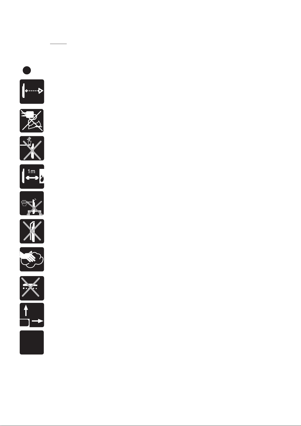
Important notes on safety!
Your safety and the safety of others is important. Please, therefore, ensure you read the Safety
instructions
before
you operate this television.
Safety instructions
Read all the safety instructions before first use of your TV.
!
• Position the television so that direct light does not fall on the screen. Excessive light
will cause a washed out effect.
• Position the power supply lead and other leads so that they are not likely to be walked
on or pinched by things placed on or against them.
• Do not place objects filled with liquid such as vase or flower pot near the television.
• Do not expose the TV to dripping or splashing of liquids.
• Do not place naked flame sources such as lighted candles on the TV set.
• Make sure that no naked flame sources, such as lighted candles, are placed on top
of the appliance.
• Do not place the television near heat sources such as radiators, ovens, stoves, etc.
10
cm
230
• Do not push, hit or screw the screen of your product.
• The heat built up in the set escapes through ventilation holes, so do not cover the set
by drapes, clothes etc. that may block air circulation. Do not place the television on
carpet or soft furnishings.
• Never let children push anything into the holes or slots on the case.
• Clean the TV Screen using a slightly damp cloth or chamois leather. Never use abrasive
cleaning agents like liquid or aerosol cleaners.
• Remove the mains plug from the socket outlet while cleaning.
• Never apply pressure on the screen when cleaning.
• Never put your screen on hard objects. Your PDP screen may be damaged.
• If you wish to place the television on a shelf or in a wall unit always ensure there is a
minimum air gap of 10 cm around the top, sides and rear of the television, to assist
ventilation.
• Your TV set is designed to operate with mains voltages 230V AC; 50Hz. Do not connect
your TV set to power sources other than the mains supply.
• If you don't use the television for a long period, please remove the mains plug from wall
socket outlet.
• Your TV set is designed as a CLASS I apparatus, the TV set has to be connected to a
mains socket outlet with a protective earthing connection.
•To fully disconnect the TV, the mains plug is used as a disconnecting device and therefore
shall be readily operable.
Page 7

PC FORMATS DOS Modes 640 x 400 and 720 x 400
VGA (640 x 480) @ 50Hz - 90Hz repetition rate
SVGA (800 x 600) @ 50Hz - 90Hz repetition rate
WVGA (848 x 600) @ 50Hz - 90Hz repetition rate
XGA (1024 x 768) @ 50Hz - 90Hz repetition rate
IMAGE FORMATS 4:3, 16:9, auto, zoom, letterbox, subtitle
INPUTS/VIDEO Mini DIN................Y/C / Hi 8 (PAL, SECAM, NTSC)
Cinch.....................CVBS Video In (PAL, SECAM, NTSC)
SCART 1 ................CVBS, RGB (PAL, SECAM, NTSC)
CVBS output
SCART 2 ................CVBS, RGB (PAL, SECAM, NTSC)
CVBS output
RF Tuner.................VHF/UHF/HYPERBAND for terrestrial
antennas or cable networks (47MHz to 861 MHz)
(PAL, SECAM)
PC DVI (D)...................VGA/SVGA/WVGA/XGA
Digital (DVI)
AUDIO INPUTS Y/C (S-Video) - CVBS
SCART 1
SCART 2
PC
OUTPUTS Cinch.....................L/R Audio Output
loudspeaker............2 x 7W sine @ 4 Ω
Cinch.....................CVBS Output
CONTROL On-Screen Display Menu.......24 languages
IR remote control
VIDEOTEXT TOP FLOF...............800 pages of memory
control with special keys on the remote control
OPERATING VOLTAGE RANGE 170V - 240V AC alternating voltage
50Hz
POWER CONSUMPTION 275 W
Page 8

Special Features
• 42’’ PDP VGA Panel
• 852x480 pixels
• 16,722,216 color (8 byte)
• Available for Cable Channels (A decoder may be required)
• 3000:1 contrast ratio
• 2x7 W Stereo sound (With detachable speakers)
• 800-Page Teletext Feature
• PIP (Picture in Picture) Feature
• Wide angle perspective
• SCART socket, AV Socket and external sound system connection
• S-VHS and Cinch inputs for S-Video connection
• DVI connection
• PC connection
• AVL – Automatic Volume Limiting
• ATS – Automatic Tuning System
• Programmed power off
• Graphic equalizer
• Color Transfer sharpness feature (CTI)
• Black-White Transfer sharpness feature (LTI) and picture sharpness
• Compound Filter (Digital Comb Filter) Feature for clear images
• On screen viewing of all control commands, program numbers and additional features
• Manual Fine Tuning
• 100 Program memory
• Infrared Remote Control
• Child lock (this feature works like a Panel Lock)
• Ability to watch NTSC broadcasts through SCART input
• East handling through an advanced menu system. Abiltiy to choose from 24 languages.
Page 9
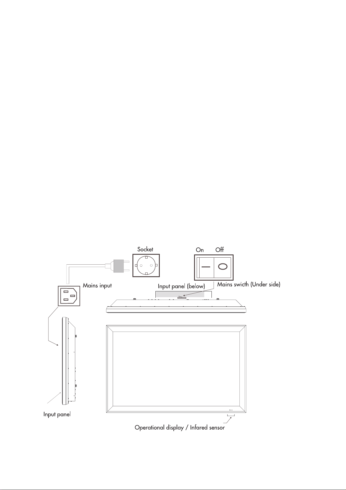
Connection of Mains Cable
Always utilise the enclosed mains cable in order to
guarantee optimal image quality.
First of all, insert the main cable into the input panel,
and only thereafter into the socket.
• Never utilise a damaged mains cable!
• Use only sockets with a protective eathing conductor
system to ensure safe operation.
A line filter and switches for sabilisation of the supply
voltages ensure safe operaion within normal mains
voltage variations. In case the mains voltage lies
beyond the stated limits, please contact your responsible
sales office. In the event the mains cable cannot be
utilised on account of differing standards in your
country, please see to it that you utilise a mains cable
commensurate with the country-specific standards
which are listed in the following:
•USA UL
• Germany VDE
• Canada CSA
• Switzerland SEV
• Great Britain BASE/BS
• Japan MITI
This list is not complete. For reasons of safety it may
be necessary to select a different safety standard.
At any rate, the mains cable has to consist of three
wire conductors of at least 10A/0.75 mm2 in order
to avoid an accident as a result of electric shock. One
of the three wires is impemented on both ends of the
cable as an earthing contact connection.
Page 10
Turning On the Plasma Display
You can only control your plasma display with the
remote control when the device is in stand-by mode.
Switch the mains switch in the input panel into Position I.
The operational display on the front side of the display
screen lights up red.
• Press a numeric button or the Program
Up / Program Down button on the
remote handset or PR+ / PR- or MENU
button on the front panel of the TV to
switch the TV on. The standby indicator
turns into green. The picture will appear
after a few seconds.
Press the Standby button to switch the
TV to standby. The standby indicator turns
into red.
• The plasma display is always connected to the
power supply network in stand-by mode. You must
switch the mains switch into position 0 and pull the
mains plug from the socket for complete disconnection.
• Display has a mains adapter, and can be operated
with a supply voltage of 230V AC and 50HZ.
Note 1: Your TV will go to stand-by mode in five
minutes if there is no broadcast signal.
Note 2: Your TV is equiped to operate with front
panel buttons, “MENU”, “SOURCE”, “
“
VOL ” in case your R/C is broken or the
PROG ”,
batteries are exhausted.
Operating Modes
Operating mode at the beginning of utilisation
Due to the functionality of the Plasma-TV please pay
attention, that particularly during the first 100 to 150
operation hours the display has to operate with a full
screen format adjustment (see submenu Display, Picture
Format). This prevents the formation of brightness
differences in the display areas. As an alternative to
the picture format 4:3 the adjustment Video NLS should
be selected.
Further on, in order to prevent the formation of permanent
shadows in the displayed image, please avoid to show
fixed-images of any kind (PC mode, teletext pages,
Photo CD image etc.) during the first operation hours.
If the Plasma-TV will be used as a PC monitor, the
utilisation of a screensaver is recommended.
PC mode
For optimal image reproduction, we recommend the
848 x 480, 640 x 480 or 720 x 400 pixel resolutions.
The 848 x 480 pixel resolution corresponds to the
display matrix, and offers the best image reproduction.
You can obtain the driver for this resolution on the
Internet pages of mont of the well-know manufacturers
of graphics cards.
In contrast to applications with CRT monitors, with flat
displays it is not necessary to select a high image
refresh for a flicker-free presentation. A refresh of
60Hz is recommended.
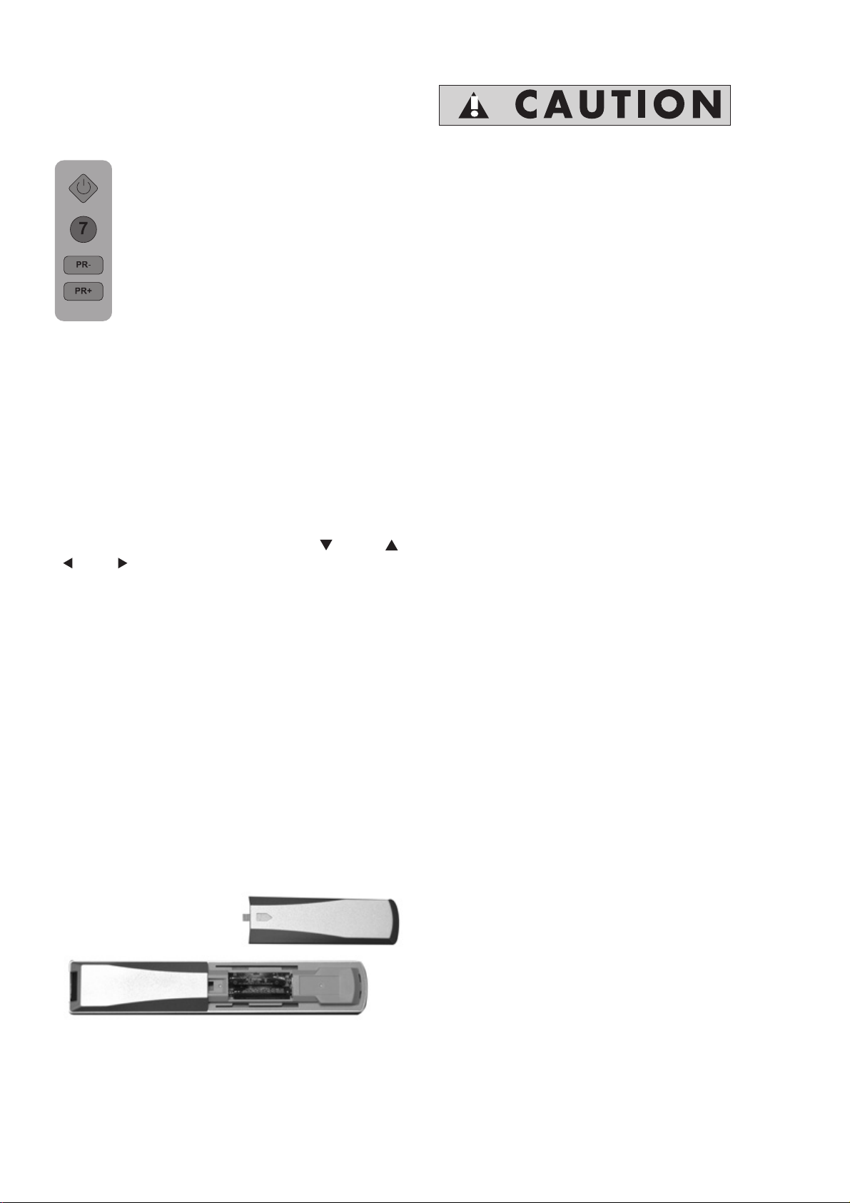
The batteries
Remove the back cover to reveal the battery
compartment and make sure you insert the batteries
the right way round.
Suitable battery types for this remote are UM-4, IEC
R03 or AAA 1.5V.
Do not combine a used, old battery with a new one
or mix battery types.
The performance of the remote control will deteriorate
beyond a distance of 8 metres or outside an angel
of 30 degrees from the centre of the TV.
Video recorder mode
The utilisation of Y/C (S-Video) inputs is recommended
for enhancement of image quality - if your recorder
offers playback in Y/C (S-Video) format.
DVD player mode
The application of the RGB operating mode, which
can be connected to the SCART 1 input, is
recommended for optimal utilisation. In case your
player does not offer this operating mode, please use
the Y/C (S Video) signal mode.
Image sticking
The manufacturer would like to point out to you that
during lengthy viewing of freeze pictures (e.g. PC
playback), the image is still slightly visible in the full
mask for a few minutes during the subsequent playback
of a different source. This is known as “image sticking”
This “vanishing” residual image is caused by the
system, and does not represent a flaw. Therefore it
can not be considered as a case for warranty claim.
Video cable
A high-quality 75Ω coaxial cable should be utilised
for the connection of the video signal. Poor quality
signal cable can result in strong disturbances and
formation of shadows in the displayed image, as well
as exceeding the permissible EMC level. The
mechanical interlocks of the individual plug-and-socket
connectors are necessary for perfect and safe operation
of the device.
Page 11
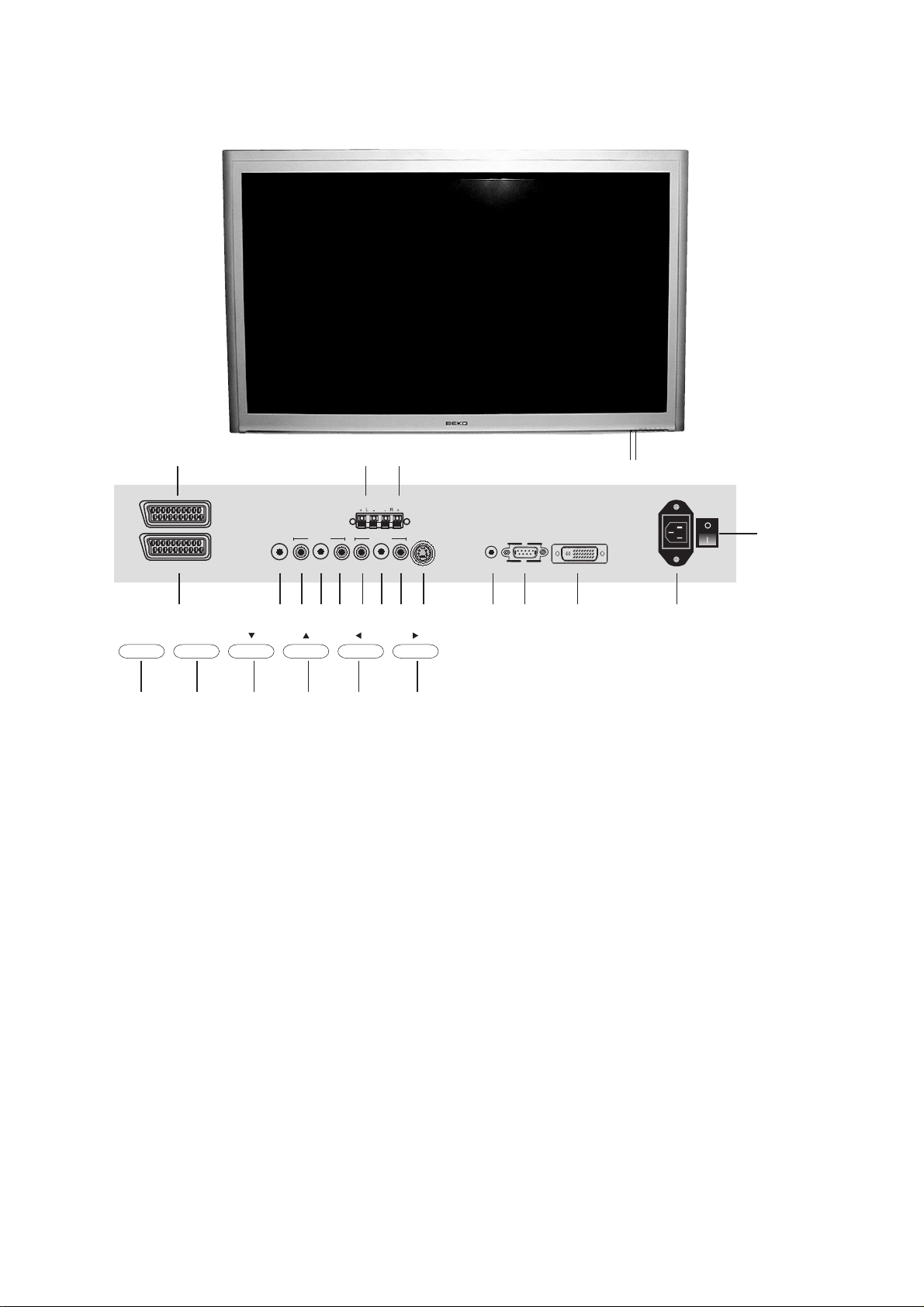
Control Unit
5
SCART - 2
SCART - 1
4 19
1.
Remote control
2.
Stand-by
3.
Power on / off
4.
Scart 1
Scart 2
5.
Antenna input
6.
7.
Video input CINCH connector
Audio RCA input (L)
8.
Audio RCA input (R)
9.
Video output CINCH connector
10.
Audio RCA output (L)
11.
Audio RCA output (R)
12.
S-VHS
13.
14 15
SPEAKER OUT
AV IN AV OUT
ANT VIDEO L R VIDEO L R
6 7 8 9 10 11 12 13 16 17 18
PROGMENUSOURCE VOL
SVHS
252423222120
14.
Speaker out (L)
15.
Speaker out (R)
PC sound input
16.
VGA
17.
DVI-D
18.
Power Input
19.
Source Select
20.
Menu button
21.
Program down
22.
Program up
23.
Volume down
24.
Volume up
25.
PC
AUDIO IN
VGA PC DVI - D
12
3
Please note
• Do not use Video RCA and S-Video connections at the same time, otherwise they will effect the
picture each other.
• RGB inputs from scart will give you better picture quality.
Page 12

Remote control
1
2
3
4
5
6
7
8
9
10
11
12
13
14
15
16
17
18
19
20
21
22
23
24
25
26
27
28
29
30
31
32
33
34
35
36
1. Picture Format choice button ( )
2. Temporary sound mute button (
3. Equalizer selection button (
)
)
4. PIP Position choice button
5. PIP/PAP On-Off button
6. AV modes select button
7. Numeric buttons
8. ZOOM mode choice button
9. Program down button (
10.Upward movement (
11.Volume down button (
12.Left movement (
) (Menu)
)
) (Menu)
)
13.Confirmation and Temporary
picture freezing button (Freeze) (
14.Info / Txt index page button (
15.Down button (
) (Menu)
16.Txt Question/Answer button (Reveal) (
17.Red Fastext Button (
)
18.Teletext enlarge button (Double) (
19.Blue Teletext Button (
)
)
)
)
)
20.Teletext / Mix choice buttons ( )
21.UPDATE Button (
22.Yellow teletext Button (
23.Stand-by On/Off button (
24.Picture mode choice button (
)
)
)
)
25.PAT (Picture and Teletext) Mode
On-Off button
26.PIP size button
27.PC mode input button
28.TV mode input button
29.Return to Selected Program Button (SWAP) (
30.Program Up button (
31.Volume Up button (
32.Right button (
) (Menu)
)
)
33.MENU button
34.Txt Stop Button (Hold) (
35.Green teletext button (
36.SUB PAGE Button (
)
)
)
)
Page 13
Using the TV
Turning on for the first time and Tuning
TV controls
Temporary On-Off (STAND-BY)
When you press the red (
button (temporary on-off function) located
on the upper right hand side of your
remote control of your television when
it is switched on;
indicator of your television will light red.
To switch your television back on, either
press the same button, any of the number
buttons or one of the (
Caution!
If you are not going to use your television
for a long period of time, make sure to
switch it off from the main power button.
There are certain settings which you must make
when setting up the television.
When you first switch it on, the Language menu
appears.
1. Select the menu language by pressing
)/( ) buttons.
) stand-by
( ) or
( ).
2. Select Country with (
the country where you are located with
) or ( ) and then select
( ) or
( ).
3. Select Station search with (
) to start the search.
(
• The automatic station search starts. This may last
a minute or longer, depending on the number
of television stations received.
• After the search, the station list appears.
You can delete any stations which have been
saved more than once. You can also move stations
to a different preset position, and change or
enter the station names.
) or ( ) and press
Programme selection
Press the ( )/( ) buttons on your
remote control, or by selecting a numeric
button in order to get the desired channel
on your television. In order to select a
program whose number is greater than
9, you can use the numeric buttons,
punching in the desired numbers as
required. For example, to select program
12, press the numeric buttons 1 and 2
one after another.
Mute
To temporarily mute the sound of your
television, press the (
the (
on screen as an indication of the
application.
When you press the same button again, the
sound will return. During mute, when you press
the (
automatically get out of the mute function, if you
press the (
and automatically get out of the mute function.
) button the volume will decrease and
) on screen display will appear
) button the volume will increase
) button, where
Return to Selected Button
Program (SWAP)
If you wish to return to the previous
program that you were watching then
you have the ability to return with a
single function, by pressing the (
button. Regardless of whether you are
in AV, or any other program, by using
the SWAP function allows you to swap
between the program you were
watching and the last selected program. If you
hit the same button again, you will return to the
program or AV you were watching before.
)
PR 01
PR 11
PR 01
Page 14
Control Menu
Press the ( ) button. You will see the
MENU with all the headings of the
different controls on screen. The Right/left
buttons (
between the different control menu title where
you can indicate your choice by pressing the
(
) or Up/down ( )/( ) button.
In the event that you wish to exit the application
at any given stage, simply press the MENU or
TV button.
)/( ) enable you to move
Tuning the television
You can either tune the programs automatically
or manually storing them in your television.
Please Note
In the case that your television does not receive
any broadcast signals for 5 minutes it will
automatically go on stand-by. The 5 minute
countdown OSD will be on screen.
Automatic tuning and storing of
the television program channels
with ATS
Press the (
button (
You can reach this menu directly by
pressing the Blue (
Up/down (
ATS line and press the (
screen will show the ATS menu. At the
Country line select the country you want
to watch by using the Right-left (
buttons.
Afterwards press the down (
to select the autoprogram heading and
press the (
buttons. The screen will show a warning
before the Automatic Tuning.
To start Autoprogram press the (
button; the channels will be searched
automatically and those with broadcasting will
be saved from the first program into memory.At
this point, the autoprogram warning menu
appears showing an indicator that displays the
present situation of the Automatic Tuning process.
To stop the process at any given time, press the
) button.
(
After the automatic search the screen will show
the Program Table. The program numbers that
have been stored are reflected in the Program
Table, giving you the ability to assign any
program number to the channel of your choice.
To quit the station list, press the ( ) button.
) button Press the right move
) to select the Adjustment menu.
) button. Using the
)/( ) buttons select the
) button, the
)/( )
) button
) or the Right/left ( )/( )
)
The ATS (Automatic Tuning System) on your
television enables the automatic finding and
sequencing of channels.
Sequencing is done according to the selected
country channels, which broadcast Teletext and
channel names; followed by all channels with
Teletexts without channel names and then by
channels without Teletext, to be concluded by
foreign channels broadcasting Teletext with
channel names.
Page 15
Manual tuning and storing of the
television channels
If you already know the Channel
number
Press the (
button to select the Adjustment menu.
You can reach this menu directly by
pressing the (
Using the Up/down (
select the Set-Up line and press the (
button, the screen will show the Set-Up
menu. Select the program you want to
Set-Up by using the Right-left (
buttons or the numeric keys. Choose
the system in which do a search among
the system lines.
Enter the System line using the down
button(
one system, you can also select from
(
)/( ) more than one systems. Move
to the Band line using the down button
(
). Using the right-left ( )/( ) buttons
on your remote control select “C” for
the cable channels received through the
“S” antena.
) button. Press the right move
) button.
)/( ) buttons
)/( )
).Here your TV can be set to
Using the Up ( ) button select the Channel line
and enter the channel number by using the
numeric keypad or right-left buttons. If the channel
on screen is in the quality you desire and you
want to store it into memory, select the Saving
line with the down (
)
Afterwards press the (
you will see a Stored sign. The channel will be
stored according to the program number of your
choice. In order to store other channels, simply
repeat the above process. In the event that you
wish to exit the Channel Settings, simply press
the (
) button
) button.
) button, after a moment
Page 16
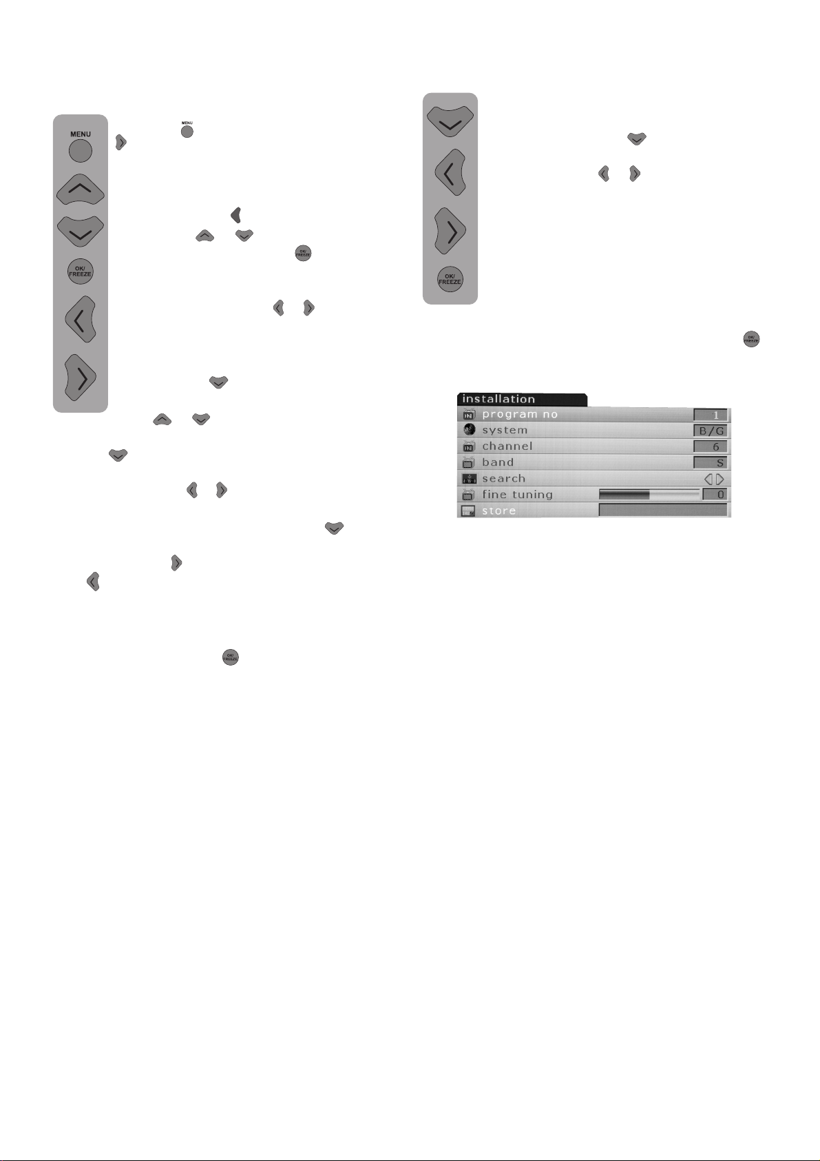
If you do not know the Channel
number
Press the ( ) button. Press the right move
(
) button to select the Adjustment
menu.
You can reach this menu directly by
pressing the (
Up/down (
Set-Up line and press the (
screen will show the Set-Up menu.
Select the program you want to Set-Up
by using the Right-left (
the numeric keys. Choose the system in
which to do a search among the system
lines. Enter the System line using the
down button(
set to one system, you can also select
from (
(option) Move to the Band line using the down
button (
).
)/( ) more than one systems.
) button.Using the
)/( ) buttons select the
) button, the
)/( ) buttons or
).Here your TV can be
Fine tuning
If the current channel requires fine tuning,
select the Manual Fine Tuning bar by
using the down (
Manual Tuning menu. Using the rightleft movement (
remote control you will have the ability
to get the exact quality of tuning
required. Under normal conditions you
will not need Fine Tuning. Your television
will automatically lock channels, which
need AFC values. However, in the event
that the TV transmitters do not work,
then you may need to use this process. For
storing the settings to the memory press (
button.
) button in the
)/( ) buttons on your
)
Using the right-left (
control select “C” for the cable channels received
through the “S” antena. Use the down (
to select the Search line, and scan the channels
using the right (
left (
line if you found the channel in the quality you
desire.
Afterwards press the (
memory. For the other channels using the Program
No line, select the program numbers you want
and repeat the same process.
If you want to Fine Tune or name the channel
you found, please refer to the concerning sections.
) button to decrease. Select the Saving
)/( ) buttons on your remote
) button
) button to increase and the
) button to store into
ENGLISH -18-
Page 17
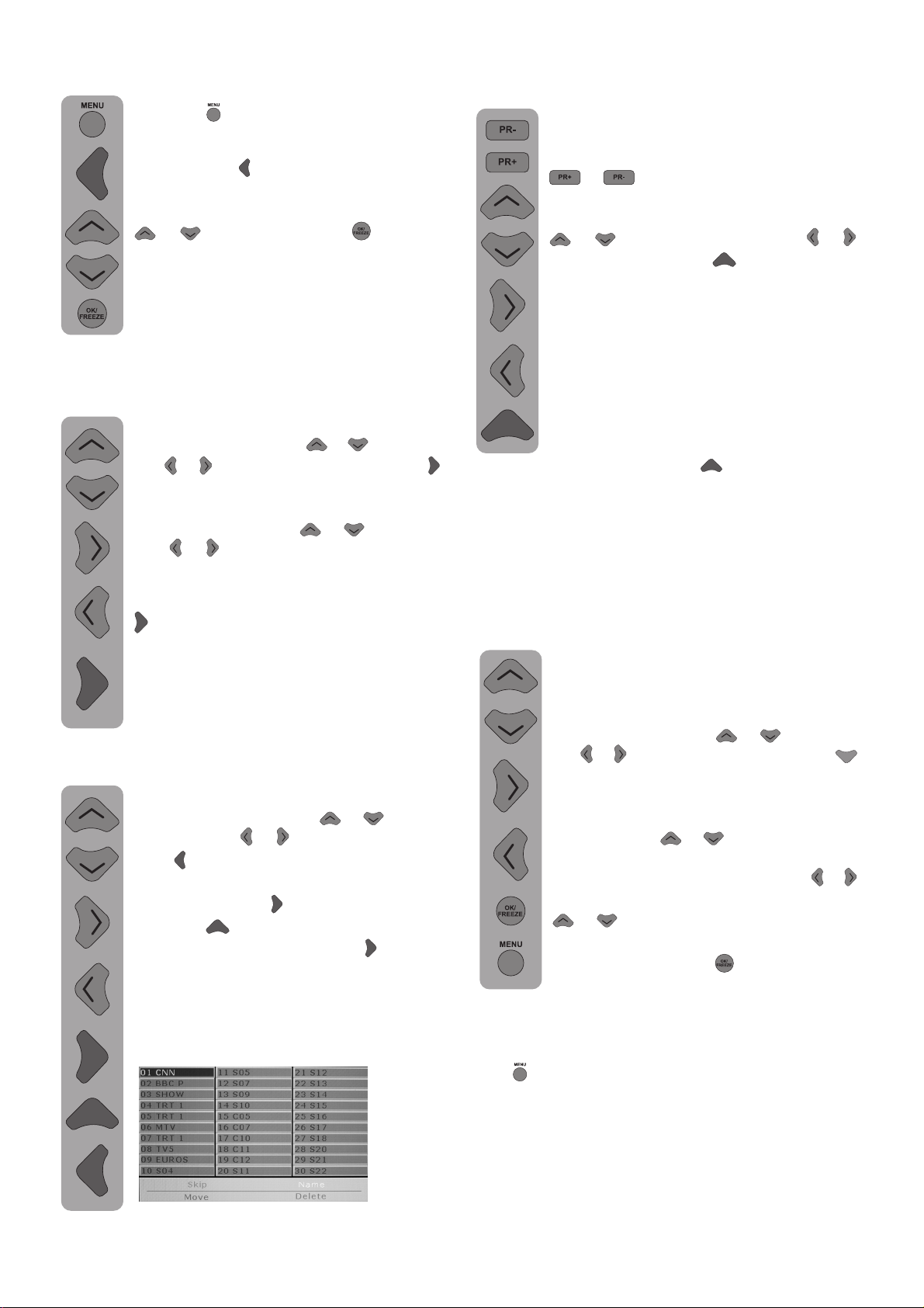
Program Table
Press the (
button to select the Adjustment menu.
You can reach this menu direclty by
pressing the (
show the program table when you select
the program table line with Up/down
(
)/( ) and press the ( ) button.
) button. Press the right move
) button. The screen will
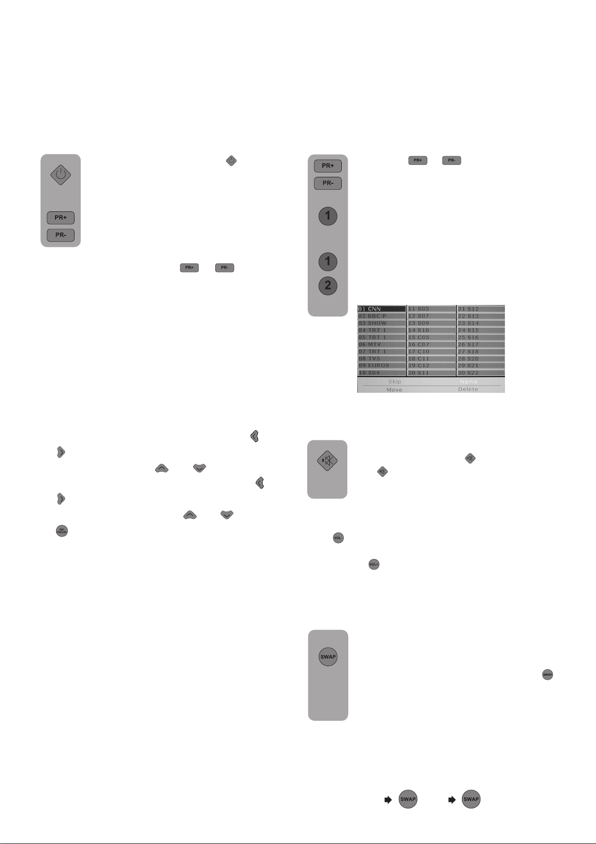
Switching the locations of the
program channels that have
already been stored
Select the program you want to switch
by using the Up-down (
left (
colored button.
number and name will appear green.
Using the Up-down (
left (
program location you want to switch.
To finish the switching press the Green
(
number indicated can be moved to the
second channel program number, which
in turn moves the initial channel program
number that has been indicated.
)/( ) button. Press the Green ( )
)/( ) buttons carry it to other
) button. The first channel program
)/( ) or Right-
)/( ) or Right-
Deleting a program that has been
stored
Select the program you want to delete
by using the Up-down (
or Right-left (
Blue (
show the confirmation menu. You can
press the Green (
the Red (
When you press the Green (
the selected channel will be deleted and
all following channels will move up in
their position accordingly.
) colored button. The screen will
)/( ) button. Press the
) button to delete or
) button to exit the menu.
)/( ) button
) button,
Skipping a program that has been
stored
In the event that you do not wish to come
across certain programs while going up
and down between channels using the
(
)/( ) buttons, then you can use
the following function. Select the program
to be stored by using the Up-down
(
)/( ) button or Right-left ( )/( )
button. Press the Red (
To the right of the name of the program
to be skipped will appear the letter “S”
in red. You have the option of applying
this method on more than one program
channel.
In order to see the program numbers
that are to be skipped, write down the
number of the concealed program
directly. To cancel the program skipping
function press the Red (
The red “S” to the right of the program name
will disappear, an the skipping will be cancelled.
) colored button.
) button again.
To name the programs
The programs in the table might show the channel
names automatically with ATS, but could also
show the channel number instead of the name.
You can name any or all of the programs
with names that have a maximum of
five characters.
Select the program you want to name
using the Up-down (
left (
)/( ) buttons.Press the Yellow ( )
button. The screen will show the number,
volume type and name information for
the channel you want to name. Using
the Up-down (
the desired letter, number or sign.
the second letter use the Right-left (
button and again use the Up-down
)/( ) buttons to select the desired
(
letter, number or sign. After entering all
the letters press the (
the name.
To write names for any of the other programs,
simply repeat the above procedure. In the event
that you wish to exit the application, simply press
the (
If no name is enter for any program, the program
number will be automatically displayed.
) button.
)/( ) buttons to select
)/( ) or Right-
)/( )
) button to store
Page 18
The setup of your television:
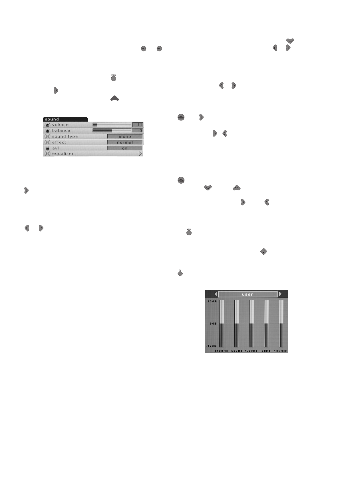
Setting up the Sound Menu
You can set the volume with the “ VOL+” and
“VOL -“ buttons on the television or the (
buttons on the remote control.
You can control the other sound settings by
entering the Sound menu For this application all
you need to do is press the (
remote control. Select the Sound menu with the
direction (
directly by pressing the Red (
the functions from the headings in this menu.
Effect: If you want to add depth to the sound of
the program you watch, select Spatial with the
(
) button.
Television transmitters have different sound levels.
This can be noticed from the different volume
levels that can be heard while switching from one
program to another. Using the right/left movement
)/( ) buttons switch to Open. The AVL
(
(Automatic Volume Limiting) function maintains
the same sound level as you switch from program
to program. To cancel choose Closed.
) button. You can reach this menu
) button of your
) button. Select
) , ( )
Balance: To adjust the volume balance between
the left and right speakers to the desired level,
select the Balance bar using the down (
Using the right/left movement (
adjust the balance.
Sound Type: The program you watch might be
stereo or in two different languages. Using the
right/left keys (
Mono/Stereo or Dual-I/Dual-II language.
Equalizer: Selecting the Equalizer mark press
) or ( ) button. The equalizer setting function
(
will be displayed. You can selected with the
right/left (
unchangeable sound enhancing Music, Sport,
Cinema and Speech, User settings for the
programs you are watching. These can be adjusted
by you in the User selection. To adjust the User
selection; select the User selection and press the
(
) button.You can adjust the frequency levels
with the (
120Hz, 500Hz, 1.5KHz, 5KHz and 10KHz
frequency bands with (
the adjustment levels in memory press the menu
button to exit the user option.
You can exit the equalizer function pressing
)button again.
the(
Please note: You can choose the equalizer
position directly from the (
remote control.
You can exit the equalizer function pressing the
(
) button at any time.
)/( ) in this menu you can select
/ ) buttons, pre-programed,
) and ( ) buttons. You can select
) and ( ) buttons. Storing
) button of your
) button.
)/( ) buttons
Page 19
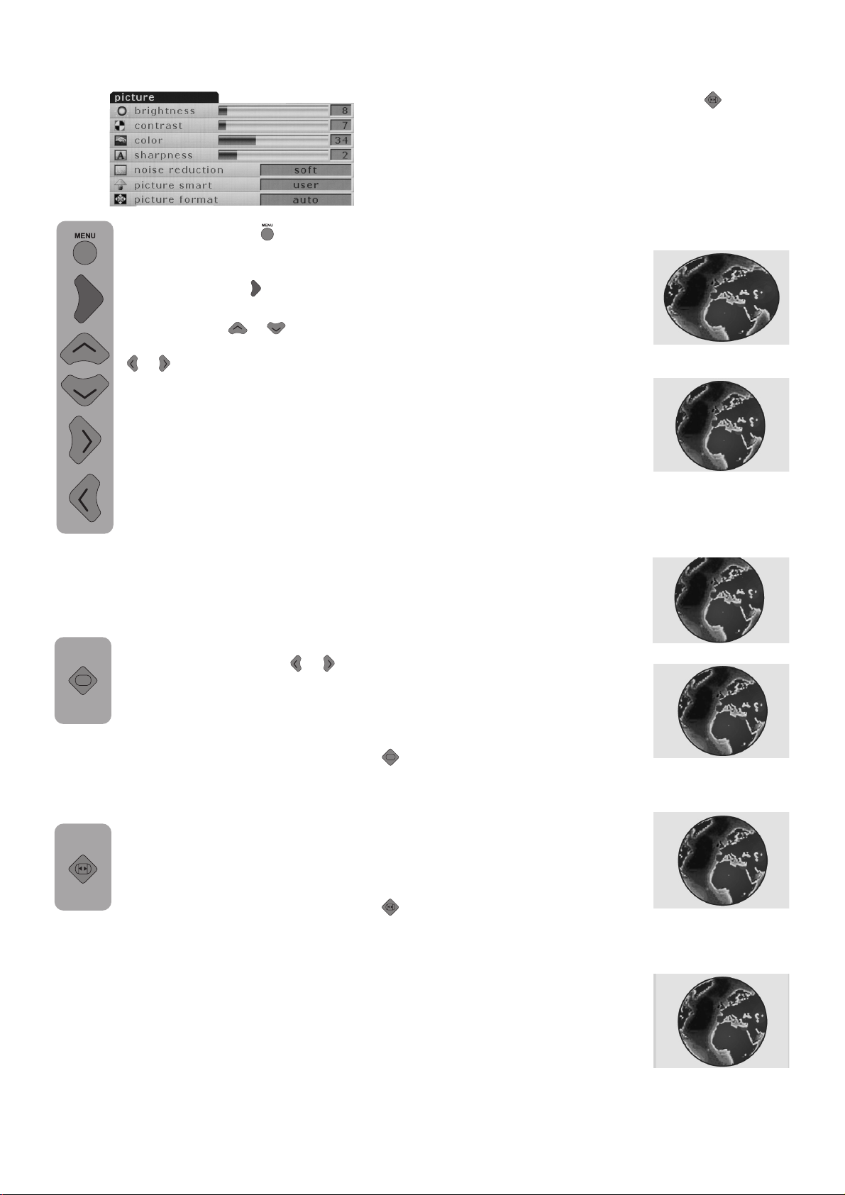
Picture Setup (Green button)
By pressing the ( ) button on your
remote control please enter the Picture
menu. You can enter this menu directly
by pressing the (
function you want using the Up and
down buttons (
levels with the right and left
)/( ).
(
The picture brightness, contrast, color
and sharpness levels can all be adjusted
according to your desire. The changes
you make in the picture settings will be
automatically stored without any further
transactions necessary being your
Personal settings.
Static Reduction: Using this feature you can
reduce static by selecting Normal, Soft, Softest,
Sharpest and Sharp function.
Smart Picture: This is one of the pre-installed
and unchangeable features, to select
this feature use your (
Soft, Natural and Rich are constant
values. User are the values you stored
into memory. Furthermore, you can select
one of the non-adjustable default settings in the
memory (Picture Mode) by pressing the “
button on your remote control.
). Select the setting
)/( ) and adjust their
)/( ) buttons.
Depending on the type of broadcast being
transmitted, programmes can be viewed in a
number of formats. Press the ”
repeatedly to select between Zoom, Letterbox,
Subtitle, Auto, 16:9, and 4:3.
Please note: Whenever the MENU button is
pressed the picture size setting will change while
the menus are ON the screen. This is to ensure
that the menus do not overlap the edges of the
viewable area.
Zoom
This setting will entarge the image
to fit the screen by streching the
image horizontally, holding the
correct proportions at the centre
of the image. Some distrotion may
occur.
Letterbox
Use this setting when watching a
widescreen DVD, widescreen video
tape or a 16:9 broadcast (when
available). Due to the range of
widescreen formats (16:9, 14:9,
20:9 etc.) black bars may be
visible on the top and bottom of
the screen. Letterbox format
removes blck bars or makes it much
less visible.
Subtitle
When subtitles are included on a
letterbox format broadcast, this
setting will raise the picture to
ensure that all the text is displayed.
Auto
Some channels may send
automatic screen formatting. If you
wish to swich automatically to this
format select Auto.
The TV will outomatically switch
“
to detected format from the scart
inputs.
“ button
Picture Format: This feature enables you to
watch any broadcast image in the format
you desire. These are; Auto, 16:9
Subtitle, Letterbox, 4:3 and Zoom. You
can do the selection without entering
the picture menu by using the ”
format selection button.
Color Tint: When NTSC video is used in SCART,
Color Tint settings can be made. If you do not
use such a video type the Color Tint choice is
not seen in the menu. If NTSC video is used in
SCART this choice becomes active and can be
seen in the menu.
16:9
Use this setting when wathching
a widescreen DVD, widescreen
video tape or a 16:9 broadcast
(when available). Due to tre range
of widescreen formats (16:9,
“
14:9, 20:9 etc.) black bars may
be visible on the top and bottom
of the screen.
4:3
Use this setting to view a trie 4:3
broadcast.
Using the special functions to change the size of the
displayed image (i.e. changing the height/width ratio) for
the purposes of public display or commercial gain may
infringe on copyright laws.
Page 20
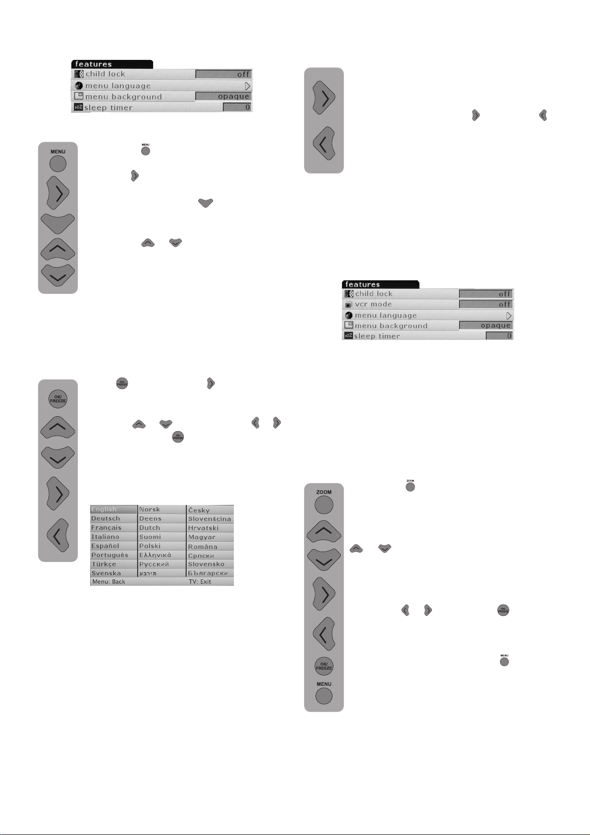
Features Menu (Yellow Button)
Press the ( ) button on your remote
control. Select the Function menu line
with the (
You can reach this menu directly by
pressing the Yellow (
can select the headings you want to
adjust in this menu by using the
Up/down (
Child Lock: If you switch this feature On, the
buttons on the TV will not work when the TV is
in Stand-by mode or on and screen will show
a Child Lock warning.
) button.
) button. You
)/( ) buttons.
Stand-by Control: Your television features an
automatic stand-by feature which can be enabled
between 15 and 120 minutes. If you
want your television to autmatically go
into stand-by, please select the Standby Control line. Select the desired
duration with the Right (
button.
At the end of the choosen duration the
screen will show a 30 second countdown
before switching off the screen and
entering into stand-by. To cancel the
automatic stand-by select “0” at the Stand-by
Control.
VCR mode: Using this feature you can avoid
image distortions from the device or the magnetic
tape while watching. For this you have to swtich
the VCR mode to ON.
) and left ( )
Language: Select the menu language line and
press (
screen will show the menu languages.
Select the desired language using the
Up-down (
buttons. Press the (
television will now feature the language
you have choosen for all the adjustment
indicators.
Menu Background: Using this feature you
can adjust the background of the viewable menus
and other OSDs as Transparent or Opaque.
) or the right ( ) button. The
)/( ) and Right-left ( )/( )
) button again. Your
Please note: This feature is only active for the
AV inputs. This feature will not be seen in Function
menu while watching programs or in PC mode.
This feature becomes automatically active in the
”0” numbered program.When you store the “0”
numbered channel as video device antena output,
you will be able to avoid image distortions from
the device or the magnetic tape while watching.
ZOOM: To activate this feature you have to
press the (
control while watching a program.
When you enter this menu you will see
in the lower right corner of the screen
the Zoom sub-menu. Using the Up/down
)/( ) buttons you can enlarge or
(
shrink the image in 16 steps. During the
Zoom process the image will be enlarge
focused on the center.
want to move the image up/down or
right/left (
on your remote.
buttons to move around.
In the event that you wish to exit the
Zoom menu, simply press the (
Please Note: The Zoom function is not
available during PIP.
) button on your remote
)/( ) press the ( ) button
) button.
Page 21
FREEZE: This feature enables you to freeze the
image of a program you are watching.
For this use the (
) button on your remote
control, make sure you don’t have any
menus on screen. The image will be
frozen until you press the button the
second time.
Please Note: The Freeze function is not
available during PIP.
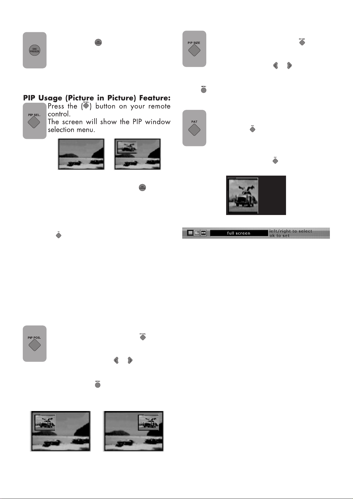
PIP Size
This feature enables you to resize your
PIP window. For this press the (
) button,
while having PIP on screen, to bring the
PIP Size menu on screen.
Press the right/left (
)/( ) buttons to
make the PIP Size selection. After resizing your
PIP window you can exit the menu by pressing
the (
) button on the remote control.
PAT Mode
While watching TV you can enter the
PAT (Picture and Teletext) mode by
pressing the (
) button on your remote
control. This feature enables you to read
the program’s teletext, if available, while
watching the very same program.
To exit this mode press the (
) button on your
remote control again.
In this menu select either Picture in Picture (PIP)
or Divided Screen (PAP) and press the (
) button.
According to the selection a picture will open in
main picture and will position itself in the lower
screen.
If you choose Full Screen mode PIP will go out.
In the event that you wish to exit PIP mode, simply
press the “
” button.
Note:
1) From the program you are watching or from
AV mode, you can open the PIP window, and
change the other programs through the main
image.
2) You can use PIP in PC or DVI mode.
3) The same AV input cannot be watched with
PIP and the main image.
PIP Position
This feature enables you to position your
PIP window. For this press the (
) button,
while having PIP on screen, to bring the
PIP Position menu on screen.
Press the right/left (
)/( ) buttons to
make the PIP Position selection. After you
positioned your PIP window you can exit the
menu by pressing the (
) button on the remote
control.
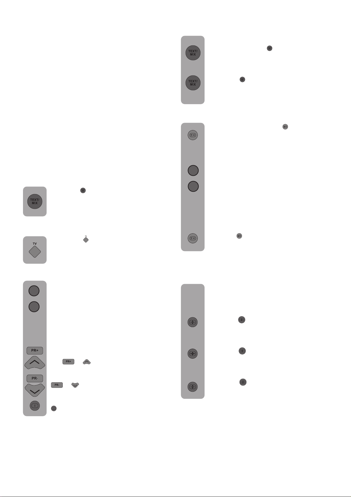
Teletext
Mode
Page 22
Using Teletext
Teletext is an information system that displays
text on your TV screen. Using the teletext control
buttons you can view pages of information that
are listed in the teletext index.
Please Note
No on screen display is available in text mode.
The contrast, brightness and colour cannot be
changed but the volume control is still available.
To enter Text mode
Please Note
Make sure the TV channel you are watching
transmits teletext.
Press the (
appear, normally the index page.
To exit Text mode
Press the (
return to the channel you were watching.
) button. The text page will
) button. The screen will
TV/Text mix
To view a TV programme whilst in text
mode, press the (
will be superimposed over the TV
programme.
Press the (
the channel you are watching.
) button again to return to
) button. The text
Page search whilst watching TV
In Text mode press the (
TV will return to TV mode with the text
page number in the top left hand corner
of the screen.
Enter the page number you want using
0
the Numeric buttons.
9
The top line of the text page will appear
whilst the text searches for your page.
When the page is found the number will
remain in the top left hand corner of the
screen.
Press the (
page of text.
) button to view your selected
) button. The
To select a page of text
Find the number of the page in the index
0
and enter it using the Numeric buttons.
The number of the page will appear in
9
the top left hand corner of the screen.
The page counter will search for your
page. When it finds it, the page will be
displayed.
To move to the next page of text press
the (
To move to the previous page press the
(
To return to the index page press the
(
) button.
)/( ) button.
)/( ) button.
Double height text
If you have difficulty reading the
text on the TV you can double the height
of the text.
Press the (
page will be displayed in double height
text.
Press the (
half of the page will be displayed in
double height text.
Press the (
the full page.
) button. The top half of the
) button again. The bottom
) button again to return to
Page 23

Page Stop
To reveal information
If the page of text you have selected
contains sub pages, these sub pages
will automatically be displayed in order
with a delay to allow you to read the
page.
To stop the move to the next sub page
press the (
To continue moving through the sub
pages press the (
) button.
To select a sub page
If the page of text you are viewing
contains sub pages, the number of the
sub page you are on and the total
number of sub pages is displayed on
the right of the screen i.e. 1/7.
To select a sub page press the (
button. Press the green button to select
next sub-page or press the red button
to select the previous sub-page.
5
Enter the number of the sub page, using
the Numeric buttons in the format S0001
for sub page 1.
) button again.
Press the (
information (quiz answers etc.).
Press the (
the information again.
) button to reveal concealed
) button again to cancel
Clock
Press the (
TV program , to display the time.
) button, whilst watching a
Fastext
At the bottom of the teletext screen is a row of
subject headings in red, green yellow and blue.
The remote control has a row of coloured buttons
corresponding to the row of coloured subjects
)
on the screen.
Pressing one of the coloured buttons will take
you directly to the page corresponding to the
subject heading.
The teletext will search for the sub
page. This may take some time. To
return to the TV whilst the teletext is
searching press the (
When the page number is found it will
appear in the top left hand corner of
the screen.
Press the (
text page.
) button again to view the
) button.
Page 24

Connecting external equipment
AV Inputs:
Press the ( ) button on your remote control. You
will enter the Source menu from where you can
elect the screen input mode. Here select the input
you desire.
TV: To move to TV mode while in AV modes,
move on to the selection and press the (
button.
Scart1: To be able to view the broadcasting
images form the device connected to Scart1,
move on to the selection and press the (
button. (If the connected device has an RGB
output, you will be able to watch it over Scart.)
Scart2: To be able to view the broadcasting
images form the device connected to Scart2,
move on to the selection and press the (
button. (If the connected device has an RGB
output, you will be able to watch it over Scart.)
SVHS: To be able to view the images form the
device connected to the S-Video input, move on
to the selection and press the (
) button.
AV: To be able to view the images form the
device connected to the RCA (Chinch) input,
move on to the selection and press the (
) button.
PC: To be able to view monitor images in PC
mode, move on to the selection and press the
(
) button.
DVI: To be able to view images in DVI mode,
move on to the selection and press the (
) button.
Connecting a video recorder
Via SCART
Make sure the TV and video recorder are both
switched off.
Plug one end of the SCART lead (not supplied)
)
into the back of the video recorder and the other
end into one of the SCART sockets on the back
of the TV.
Switch on the video recorder and the TV.
)
Press the (
control to select SCART1 or SCART2 to
correspond with the SCART socket you
are using on the back of the TV.
)
Please note: You can connect RGB external
equipment via Scart. It is necessary to you use
a full Scart cable for this purpose.
Select the video output of the external device
by using its menu, and set to RGB.
) button on the remote
Via RCA lead (optional)
Make sure the TV and video recorder are both
switched off.
Plug one end of the RCA lead into the video and
audio out sockets on the back of the video
recorder and plug the other end into the video
and audio in sockets of the TV.
If the sound is mono, use the Audio Input L. and
in the SOUND menu select the MONO feature.
Page 25
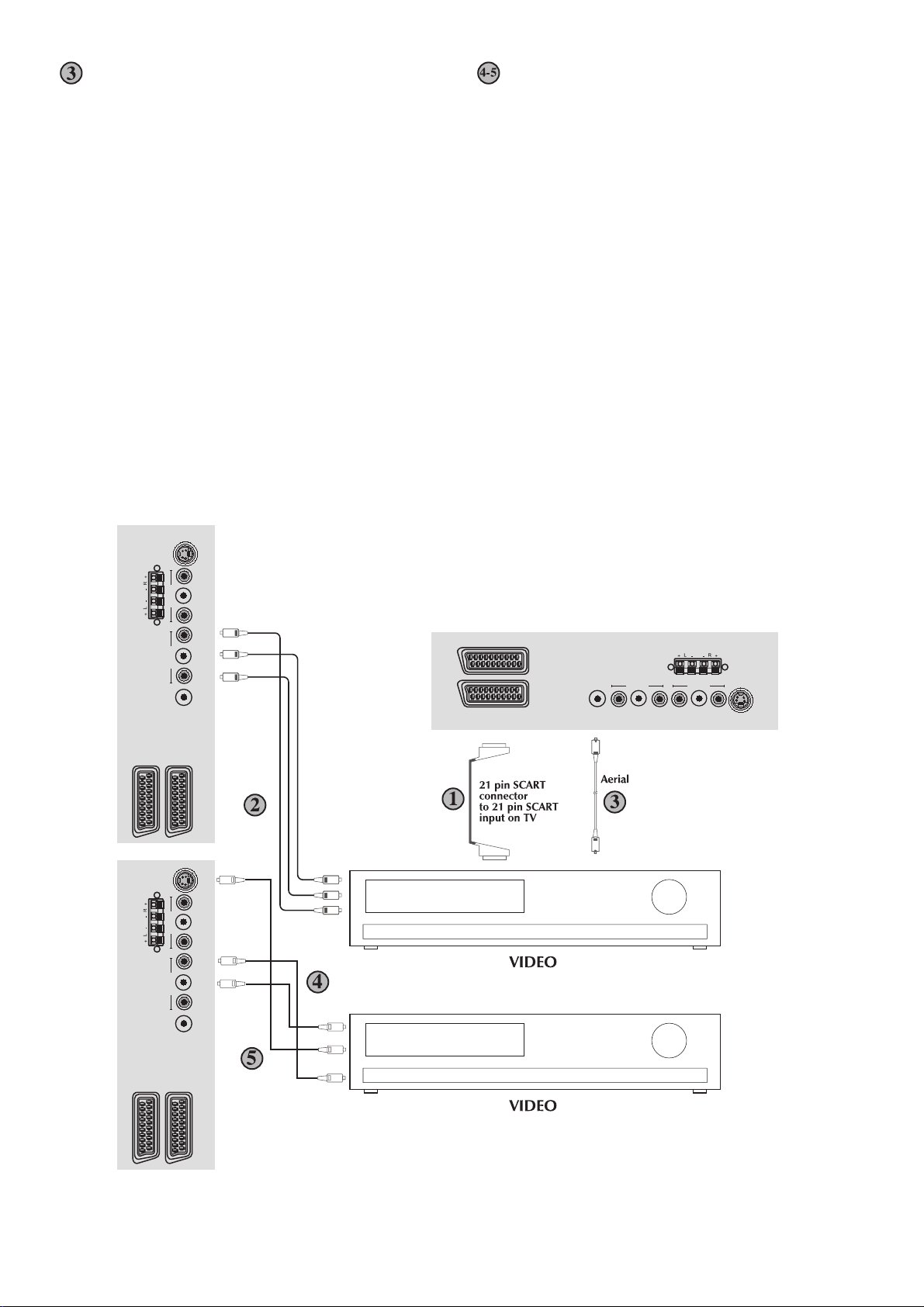
Via aerial socket
Via RCA lead and S-Video socket
Make sure the TV and video recorder are both
switched off.
Unplug the aerial lead form the TV and plug
it into the aerial socket on the video
recorder.
Plug a coaxial plug into the RF out socket on
the rear of the video recorder and plug the
other end into the aerial socket on the TV.
Switch on the video recorder and the TV. If
your video recorder has a test signal, switch
it on. (Refer to the video recorder user guide).
See ‘Tuning the TV’ and carry out the tuning
procedure for the video recorder test signal.
Select a programme number 0.
You can also connect it through the
S-Video socket of the TV.
Plug the S-Video plug into the S-Video socket
and the audio leads into the audio sockets.
SVHS
SPEAKER OUT
AV IN AV OUT
SCART - 1
SCART - 2
SVHS
AV IN AV OUT
SPEAKER OUT
ANT VIDEO L R VIDEO L R
Audio In (R)
Audio In (L)
Video In
S-Video In
Audio In (R)
Audio In (L)
SCART - 2
SCART - 1
SPEAKER OUT
AV IN AV OUT
ANT VIDEO L R VIDEO L R
SVHS
SCART - 2
ANT VIDEO L R VIDEO L R
SCART - 1
Page 26
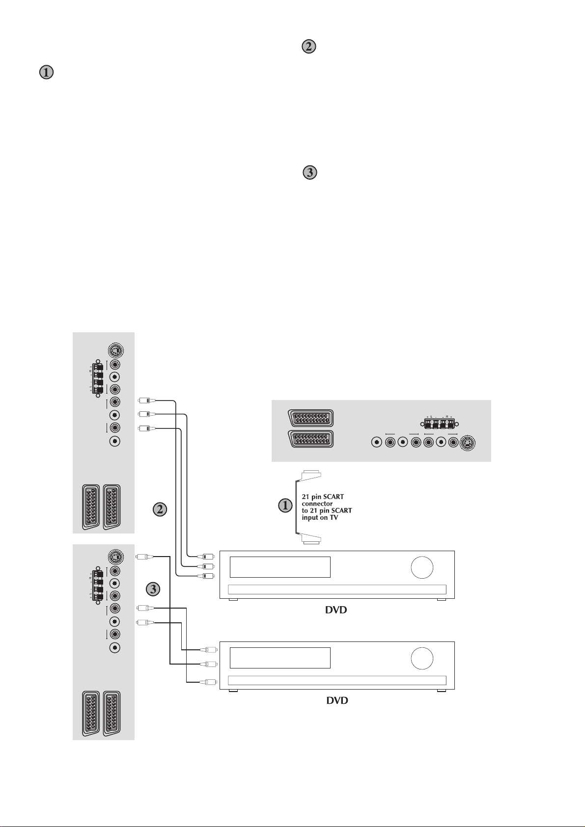
Connecting a DVD player
Via RCA lead
Via SCART
Make sure the TV and DVD player are both
switched off.
Plug one end of the SCART lead (not supplied)
into the back of the DVD player and the other
end into the SCART socket on the back of the
TV.
Switch on the DVD and the TV.
SVHS
Make sure the TV and DVD player are both
switched off.
Plug one end of the RCA lead into the video and
audio out sockets on the back of the DVD player
and plug the other end into the video and audio
in sockets of the TV.
Via RCA lead and S-Video socket
You can also connect it through the S-Video
socket of the TV.
Plug the S-Video plug into the S-Video socket
and the audio leads into the audio sockets.
AV IN AV OUT
SPEAKER OUT
SCART - 1
SCART - 2
SVHS
AV IN AV OUT
SPEAKER OUT
ANT VIDEO L R VIDEO L R
ANT VIDEO L R VIDEO L R
Audio In (R)
Audio In (L)
Video In
S-Video In
Audio In (R)
Audio In (L)
SCART - 2
SCART - 1
SPEAKER OUT
AV IN AV OUT
ANT VIDEO L R VIDEO L R
SVHS
SCART - 2
SCART - 1
Page 27
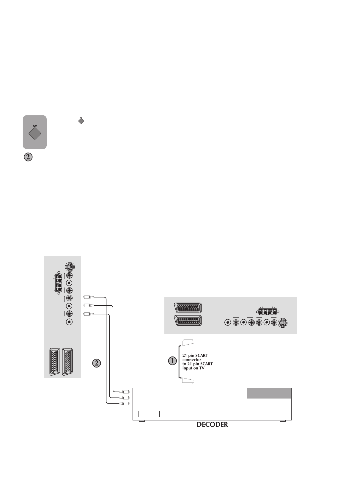
Connecting a decoder
Via SCART
Make sure the TV and decoder are both switched
off.
Plug one end of the SCART lead (not supplied)
into the back of the decoder and the other end
into the SCART on the back of the TV.
Switch on the decoder and the TV.
Press the (
) button on the remote control
to select SCART1.
Via RCA lead
Make sure the TV and decoder are both switched
off.
Note: For Decoder connection Via RCA lead
your Decoder device must have the tuner built
in.
Plug one end of the RCA lead into the video and
audio out sockets on the back of the decoder
and plug the other end into the video and audio
in sockets on the TV.
Connecting DVI-D
Your TV has DVI-D input socket. You can connect
any device such as PC etc. which has DVI digital
out using the proper cable. At the same time you
can listen to the sound from the connected device.
PC or DVI use a special cable to PC-DVI/AUDIO
IN input at the back of your TV.
AV Outputs
You can connect any device which is proper to
Phono inputs via Phono Video and Audio Outs
at the back of your TV set using proper AV cable
(not available with the set).
Any programme or AV input which is seen on
the main screen other than S-VHS, PC or DVI
(which is option) is available as picture and sound
signals at Phono Video/Audio outs.
Scart sockets at the back of your TV set are always
give the signals of selected programme from the
set Tuner.
SVHS
AV IN AV OUT
SPEAKER OUT
SCART - 1
SCART - 2
ANT VIDEO L R VIDEO L R
Audio In (R)
Audio In (L)
Video In
SCART - 2
SCART - 1
SPEAKER OUT
AV IN AV OUT
ANT VIDEO L R VIDEO L R
SVHS
Page 28
INTRODUCTION
Because your 42” 16:9 PDP-TV equipment is provided with VGA inputs, it may be used as a PC
monitor as well. (Pug&Play)
Connecting PC:
Connect your PC through the D-Sub connector
and an appropiate cable (not inlcuded with your
TV) to PC-IN input the back of the TV.
Again using an appriopiate cable you can
connect your PC sound output to the PC-DVI /
AUDIO IN input on the back of the TV and listen
to sound.
Transition to the PC mode
In order for the PDP to switch to the monitor (PC)
mode, you can press the (
remote control. In order to switch from the PC
mode back to the TV mode, use the (
on your remote control.
) button on your
) button
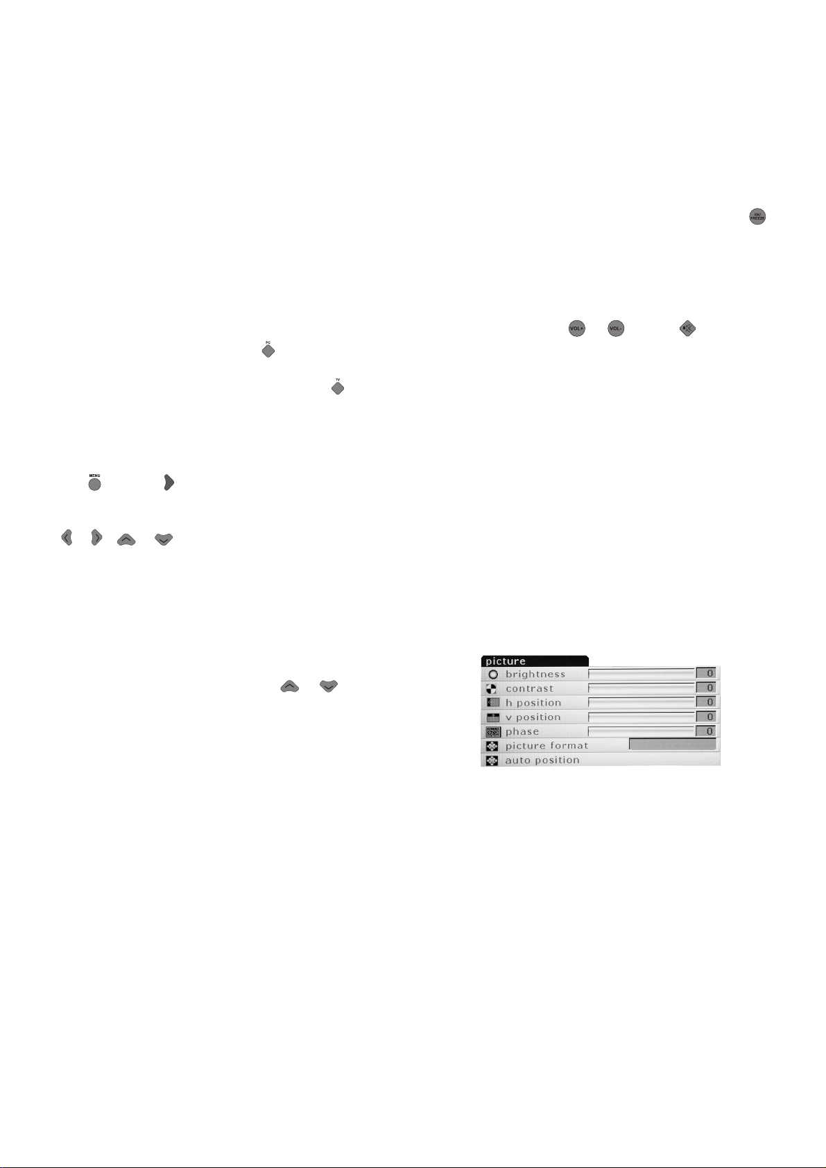
PC Input Settings
You can enter the picture setting menu by pressing
the (
make the necessary adjustments in this menu,
you can use the right-left, up-down direction
(
Here you can make adjustments to Brilliance
and Contrast as well as other adjustments for
the monitor listed below.
H.Position: Horizontal position setting
V.Position: Vertical position setting
) or the ( ) while in PC mode. In order to
)/( ) ( )/( ) buttons on your remote control.
Automatic Configuration: The most suitable
geometric settings in accordance to the entry
mode is configured by this function. For this
application, choice the AUTOMATIC
CONFIGURATION option and press the (
button.
In PC mode you are able to use ZOOM and PIP
as mentioned in the sections above.
You can adjust the volume of the device you
connect to the Audio-In input at the back of the
TV by using the (
)/( ) or /( ) buttons.
Transition to the DVI mode
Connect your PC or digital video device using
its connector and an appropriate cable (not
included with your TV) to the DVI input at the
back of your TV.Again using an appriopiate
cable you can connect your PC or sound device
output to the PC-DVI / AUDIO IN input on the
back of the TV and listen to sound.
Please Note: To be able to view images in
DVI mode your computer must have a graphics
card with DVI output.
Adjustments in DVI mode are the same as in PC
mode. However automatic configuration will not
function in this mode.
)
PHASE: Using the Right/left (
you can adjust color and shape.
Picture Format: You can select your PC viewing
image from auto, 4:3 or one-to-one.
You can make your choices without entering the
picture menu by using the format button on your
remote control.
)/( ) buttons
Page 29
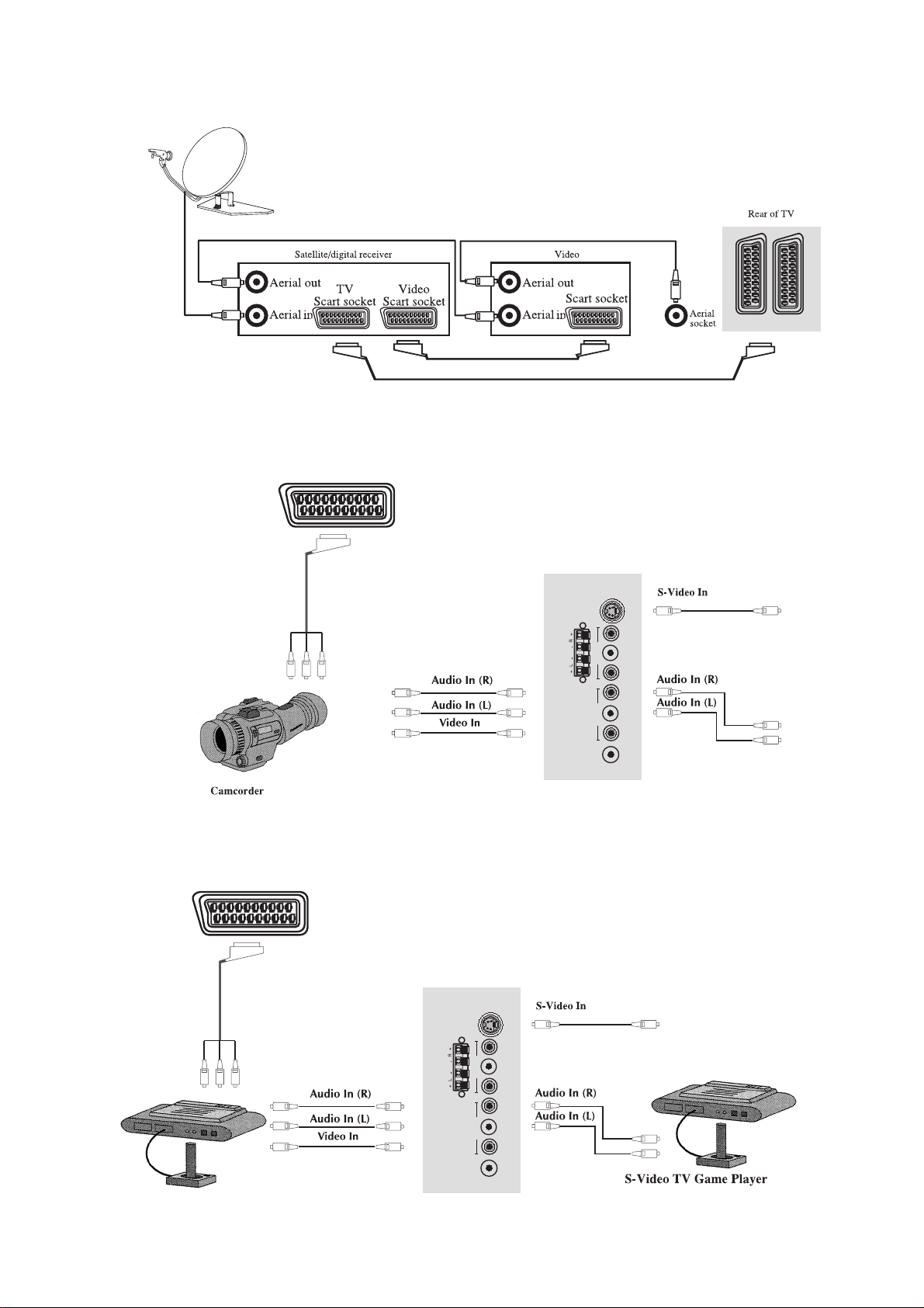
Connecting TV with video and satellite/digital
receiver
Connecting TV with camcorder
AV1
Connecting TV games and computer
AV1
SVHS
SVHS
SPEAKER OUT
AV IN AV OUT
ANT VIDEO L R VIDEO L R
AV IN AV OUT
SPEAKER OUT
ANT VIDEO L R VIDEO L R
Page 30

Technical specifications table
42” 16:9
Plazma TV
2X7 W
275 W
6 W
General technical specifications
Power Supply
AC: ..............................................................................230 V 50 Hz
Number of preset programmes:..............................100
RF Aerial input:..........................................................75 ohm (unbalanced)
Speaker empedance: ................................................4 ohm
Sound Systems: .........................................................Mono/Stereo/NICAM
Batteries:....................................................................2xUM-4, IEC R03 or AAA 1.5 V
Receiving channels:...................................................VHF (Band I Channels 2-4)
....................................................................................VHF (Band II Channels 5-12)
....................................................................................UHF (Channels 21-69)
....................................................................................Cable TV (S1-S20/S21-S41)
Receiving Broad system: ..........................................Pal BG
Pal SECAM BG
Pal SECAM BG DK/DK’
Pal SECAM BG LL'
Pal I
Page 31

L6B
Panel Power
Scart
L6B Cha
ssis
Supply
Power Supply
Adaptor
Chassis
Note: You can find more detailed informations regarding panel and panel modules in the panel
sections of the service manual.
Page 32

TO PANEL PSU
MAIN CHASSIS
SPEAKER
TO
PANEL LOCIG BORD
S50
S150
S2
S350
JP451JP452
S550
JP453
JP450
CN1
POWER
SUPPLY
MODULE
CN2CN3
IR RECEIVER/LED
MODULE
TO HEADPHONE JACK
KEY BOARD
MODULE
MAIN POWER
SWITCH
MODULE
220V AC
INPUT
Page 33

L6B BLOCK DIAGRAM
RF In
AV-Out Video
AV4 Video-In
AV4
Audio-In
Tuner-Main
Tuner-PIP
SCART 1 2 3
Audio-In/Out
Audio-Switch
TDA6420
IF IC TDA9886T
IF IC TDA9886T
Video In/Out
I2C Communication
SC1-SC2 RGB
Audio
In-Out
PIP-Video
Main-Video
Video Switch
TDA6415C
Pin 8 Switch
PCF8591
RGB Switch
PI5V30
AUDIO PROCESSOR
MSP3410D
QSS-Main
QSS-PIP
Video-Main
Video-PIP
Scart RGB
Multi Standard
Video Decoder
SAA7118MP
Multi Standard
16 Bit
YUV
SAA7118MP
Video Decoder
MT48LC16M
De-Interlacer
24 Bit RGB
16 Bit
YUV
IR In
SDRAM
PW1231
PROCESSOR
De-Interlacer
Micro-Cont.
Gamma Corr.
EEPROM
24C64
PW181
IMAGE
Scaler
OSD
48 Bit RGB VS/HS
Flash Memory
AM29VL160
Progressive
or Intrelaced
24 Bit Dual
RGB ,HS,VS
DE,PCLK
DS090C385
LVDS Transmitter
Stand by
LED’s
Reset
Mute
B/L Enable
Digital Dim
TO THE
PANEL
AV Out Audio
Headphone Jack
Headphone
Amp.
TDA1308
PC DVI Audio -In
Audio Amplifier
TA2024
Speaker
SVHS Y/C
SVHS Socket
EEPROM
24LC21
Dual İnterface for
RGB HS/VS-In
D-SUB 15 socket
FPD
AD9887
EEPROM
24LC21
DVI Input
DVI Socket
Page 34

L6B POWER SUPPLY BLOCK DIAGRAM (MAIN CHASSIS)
J450
12V F450 +2,5V_STBY
U451
FDS9933A
DC_IN
GND
S450 +3,3V_STBY
(5V) +5V_STBY
F451
U454
LM2576
VOLTAGE
DOUBLER
U458
NCP1117
GND
12V '33V +1,5V_STBY
U452
FDS9933N
STAND_BY +3,3V
U453
FDS9933N
PNL_EN +12V_INVERTER
12V_AMP
+5V
U457
NCP1117
+12V PANEL_POWER
U455
LM2576
U450
NCP117
U456
LM317
+8V
Page 35

L6B SERVICE MENU
1. Activating the Service Menu
When the menu is on the screen press ‘9’, ‘3’, ’0’, ’1’ on the remote controller. This will
activate the service menu.
2. Service Menu Structure
The service menu has three items: display, calibre and version
2.1 Display
Display item has seven options:
a- Panel
Panel option gives information about the current panel resolution. It is a read only
option and can not be set.
b- Factory mode
Used during production, keep "off".
c- Scart prescale
Scart prescale option sets the prescale values for the input sounds entering the scart
input of the MSP(Micronas Sound Processor). Changing this value you can adjust
the level of the output sound going to loudspeakers for all the sources except the
Tuners. The range is between 0 and 100.
d- nicam prescale
Nicam prescale option sets the prescale values for the Nicam standard sounds for
tuner inputs. Changing this value you can adjust the level of the output sound
going to loudspeakers for Nicam sounds entering the analog sound input of MSP.
The range is between 0 and 100.
e- fm/am prescale
fm/am prescale option sets the prescale values for the FM/AM standard sounds for
tuner inputs. Changing this value you can adjust the level of the output sound
going to loudspeakers for FM/AM sounds entering the analog sound input of MSP.
The range is between 0 and 100.
f- Agc(Automatic Gain Control) adjust
Agc adjust option sets the input voltage going to IF decoder AGC pin. Changing
this value you can adjust this voltage for optimum Tuner performance. The range
is between 0 and 31.
g- R/G/B Brightness/Contrast: These are used for color bias adjustment. The range is
Between 0 and 255
Page 36

2.2 Calibre
2.3 Version
Calibre item has nine options:
a- video format
Video format option force the video format to the desired format. Selectable
formats are Auto, Pal, NTSC and SECAM.
b- colorspace
Colorspace option gives the information about the video input colorspace input to
PW181 IC. Do not change this value unless an error occurred in the colors
displayed.
c- test pattern
This option activates the internal pattern of PW181 IC. There are 3 choices: none,
vert bars, solid color. None will deactivate the internal pattern. Vert bars choice
activates the bar pattern for the selected color component. Solid color activates the
solid pattern with one color selected in color component and also you can change
the level of the color by solid field level.
d- Color components:
This option selects the color for the internal pattern of PW181 IC. There are 4
choices: all, red, green and blue. If you choose all, you can see the white pattern
and if you choose one of the other choices you can see the test pattern with the
selected color.
e- solid field level
This option will adjust the level of the colors for the test pattern. The range is
betwwen 1 and 64.
f- Initial ATS
This option will enable or disable the Initial setup for the TV. Setting this option to
On, the TV will open from the Quick setup menu. Setting this option to Off will
disable this option.
g- factory reset
Factory reset option executes a reset operation for the NVRAM. Pressing OK
when this option is selected will erase the NVRAM and load default values to
NVRAM.
h- dpms
This option selects the Power option for the TV. Setting this option to On the TV
will switch to the last state for power on transition. Setting this to Off will disable
this option and the TV will always switch to Stand-by state while power on
transition.
i- osd timeout
This option sets the OSD timeout for the main menu structure. Selections are 5, 15
and 60 secs. The default is 60 sec.
(backlight:Not used in this product.
This item gives the information about the version of the software. Also you can see the
last modified time for the GUI(graphical user interface).
Page 37

BUS-CONTROLLED VIDEO MATRIX SWITCH
■
20MHz BANDWIDTH
■
CASCADABLE WITH ANOTHER TEA6415C
(INTERNAL ADDRESS CAN BE CHANGED BY
PIN 7 VOLTAGE)
■
8 INPUTS (CVBS, RGB, MAC,CHROMA, ...)
■
6 OUTPUTS
■
POSSIBILITY OF MAC OR CHROMA SIGNAL
FOR EACH INPUT BY SWITCHING-OFF THE
CLAMP WITH AN EXTERNAL RESISTOR
BRIDGE
■
BUS CONTROLLED
■
6.5dB GAIN BETWEEN ANYINPUT AND OUTPUT
■
-55dB CROSSTALKAT5MHz
■
FULLYESD PROTECTED
DESCRIPTION
The main functionof the TEA6415Cis to switch 8
videoinput sources on the 6 outputs.
Each output can be switched to only one of the
inputs whereas but any same input may be connectedto several outputs.
Alltheswitchingpossibilitiesarecontrolledthrough
2
the I
C bus.
TEA6415C
DIP20
(Plastic Package)
ORDER CODE : TEA6415C
SO20
(Plastic Micropackage)
ORDER CODE : TEA6415CD
PINCONNECTIONS
INPUT
DATA
INPUT
CLOCK
INPUT
INPUT
PROG
INPUT
V
CC
INPUT
1
2
3
4
5
6
7
8
9
10
20
19
18
17
16
15
14
13
12
11
INPUT
GROUND
OUTPUT
OUTPUT
OUTPUT
OUTPUT
OUTPUT
OUTPUT
GROUND
INPUT
6415C-01.EPS
Page 38

TEA6415C
BLOCK DIAGRAM
CVBS
(MAC/DEC)
CVBS
(PERI PLUG1)
CVBS
(AMTUNER)
MAC S IGNAL
(AMTUNER)
CVBS
(PERI PLUG2)
CVBS
(FM TUNER)
MAC S IGNAL
(FM TUNER)
SYNCHRO
(TTX/BTX)
PERI
TV2
TTX LUMA
CHROMA
POWER
PERI
TV1
18 17 16 15 14 13 12
1
3
5
6
8
10
11
20
PIP MAC
DEC.
GND
274
DATA GNDCLOCK V
GENERALDESCRIPTION
ThemainfunctionoftheICistoswitch8videoinput
sources on6 outputs.
Each output can be switchedon only one of each
input. On each input an alignment of the lowest
level ofthesignal ismade (bottomof synch.top for
CVBS or blacklevel for RGB signals).
Each nominal gain between any input and output
is 6.5dB. For D2MAC or Chroma signal the alignment is switched off by forcing, with an external
resistor bridge,5 V
ontheinput. Each inputcan
DC
be used asa normal input or as aMAC or Chroma
T
E
BUS
DECODER
A
6
4
1
5
C
919
PROG
CC
input (withexternal resistorbridge). Allthe switching possibilitiesare changedthrough the BUS.
Driving 75Ω load needsan externaltransistor.
It is possible to have the sameinput connectedto
severaloutputs.
The starting configuration upon power on (power
supply: 0 to10V) isundetermined.
In this case, 6 words of 16 bits are necessary to
determineone configuration.In othercase,1 word
of 16 bits isnecessaryto determineone configuration.
6415C-02.EPS
Page 39

I2C-buscontrolled single and multistandard
alignment-free IF-PLL demodulators
1 FEATURES
• 5 V supply voltage
• Gain controlled wide-band Vision Intermediate
Frequency (VIF) amplifier, AC-coupled
• Multistandard true synchronous demodulation with
active carrier regeneration: very linear demodulation,
good intermodulation figures, reduced harmonics, and
excellent pulse response
• Gated phase detector for L and L-accent standard
• Fully integrated VIF Voltage Controlled Oscillator
(VCO), alignment-free, frequencies switchable for all
negative and positive modulated standards via I2C-bus
• Digital acquisition help, VIF frequencies of 33.4, 33.9,
38.0, 38.9, 45.75, and 58.75 MHz
• 4 MHz reference frequency input: signal from
Phase-Locked Loop (PLL) tuning system or operating
as crystal oscillator
• VIF Automatic Gain Control (AGC) detector for gain
control, operating as peak sync detector for negative
modulated signals and as a peak white detector for
positive modulated signals
• External AGC setting via pin OP1
• Precise fully digital Automatic Frequency Control(AFC)
detector with 4-bit digital-to-analog converter, AFC bits
readable via I2C-bus
• TakeOver Point (TOP) adjustable via I2C-bus or
alternatively with potentiometer
• Fully integrated sound carrier trap for 4.5, 5.5, 6.0,
and 6.5 MHz, controlled by FM-PLL oscillator
• Sound IF (SIF) input for single reference Quasi Split
Sound (QSS) mode, PLL controlled
TDA9885; TDA9886
• SIF-AGC for gain controlled SIF amplifier, single
reference QSS mixer able to operate in high
performance single reference QSS mode and in
intercarrier mode, switchable via I2C-bus
• AM demodulator without extra reference circuit
• Alignment-free selectiveFM-PLL demodulatorwith high
linearity and low noise
• I2C-bus control for all functions
• I2C-bus transceiver with pin programmable Module
Address (MAD)
• Four I2C-bus addresses via MAD.
2 GENERAL DESCRIPTION
The TDA9885 is an alignment-free multistandard
(PAL and NTSC) vision and sound IF signal PLL
demodulator for negative modulation only and
FM processing.
The TDA9886 is an alignment-free multistandard
(PAL, SECAM andNTSC) vision andsound IF signal PLL
demodulator for positive and negative modulation,
including sound AM and FM processing.
3 APPLICATIONS
• TV, VTR, PC and STB applications.
4 ORDERING INFORMATION
TYPE NUMBER
NAME DESCRIPTION VERSION
TDA9885T/V3 SO24 plastic small outline package; 24 leads; body width 7.5 mm SOT137-1
TDA9885TS/V3 SSOP24 plastic shrink small outline package; 24 leads; body width 5.3 mm SOT340-1
TDA9885HN/V3 HVQFN32 plastic, heatsink very thin quad flat package; no leads; 32 terminals;
body 5 × 5 × 0.85 mm
TDA9886T/V3 SO24 plastic small outline package; 24 leads; body width 7.5 mm SOT137-1
TDA9886TS/V3 SSOP24 plastic shrink small outline package; 24 leads; body width 5.3 mm SOT340-1
PACKAGE
SOT617-1
Page 40

This text is here in white to force landscape pages to be rotated correctly when browsing through the pdf in the Acrobat reader.This text is here in
_white to force landscape pages to be rotated correctly when browsing through the pdf in the Acrobat reader.This text is here inThis text is here in
white toforce landscape pages tobe rotated correctly whenbrowsing through the pdfin the Acrobat reader.white to force landscapepages to be ...
handbook, full pagewidth
external reference signal
or 4 MHz crystal
7 (5)
DGND
REF AFC
AFC DETECTOR
SOUND TRAPS
4.5 to 6.5 MHz
FM-PLL DEMODULATOR
12 (11)18 (20)20 (22)
SIOMADSDASCL
AUDIO PROCESSING
AND SWITCHES
NARROW-BAND
4 (2)10 (9)
(18) 17
(7) 8
(3) 5
(4) 6
MHC108
CVBS
video output: 2 V (p-p)
[1.1 V (p-p) without trap]
AUD
audio output
DEEM
de-emphasis
network
AFD
C
AF
VIF2
VIF1
SIF2
SIF1
2 (31)
1 (30)
24 (27)
23 (26)
TOP
TUNER AGC
SUPPLY
V
P
C
TAGC
14 (15)
C
AGC(neg)
VAGC(pos)
VIF-AGC
(6, 12, 13, 14, 17,
19, 25, 28, 29, 32)
13
n.c.AGND
VIF-PLL
filter
(1)
VAGC
C
BL
SINGLE REFERENCE QSS MIXER
INTERCARRIER MIXER
AND AM DEMODULATOR
SIF AGC
C
AGC
VPLL
19 (21)9 (8) 16 15 (16) 21 (23)
RC VCO
VIF-PLL
OUTPUT
PORTS
22 (24)3 (1)
OP1 OP2 FMPLL
DIGITAL VCO CONTROL
TDA9885
TDA9886
MAD
I2C-BUS TRANSCEIVER
11 (10)
6 BLOCK DIAGRAM
alignment-free IF-PLL demodulators
I
2
C-buscontrolled single andmultistandard
TDA9885; TDA9886
(1) Not connected for TDA9885.
Pin numbers for TDA9885HN in parenthesis.
sound intercarrier output
and MAD select
Fig.1 Block diagram.
FM-PLL
filter
Page 41

BUS-CONTROLLED AUDIO MATRIX
.
5 STEREOINPUTS
.
4 STEREOOUPUTS
.
GAIN CONTROL 0/2/4/6dB/MUTEFOR EACH
OUTPUT
.
CASCADABLE(2 different addresses)
.
SERIALBUS CONTROLLED
.
VERYLOW NOISE
.
VERYLOW DISTORSION
DESCRIPTION
The TEA6420 switches 5 stereo audio inputs on
4 stereo outputs.
All theswitching possibilitiesare changed through
2
C bus.
the I
TEA6420
SHRINK24
(Plastic Package)
ORDER CODE : TEA6420
SO28
(Plastic Micropackage)
ORDER CODE : TEA6420D
PINCONNECTIONS
GND
CAPACITANCE
V
S
L1
L2
L3
L4
L5
LOUT1
ROUT1
LOUT2
ROUT2
SHRINK24
1
2
3
4
5
6
7
8
9
10
11
12
24
23
22
21
20
19
18
17
16
15
14
13
SDA
SCL
ADDR
R1
R2
R3
R4
R5
ROUT4
LOUT4
ROUT3
LOUT3
GND
CAPACITANCE
V
NC
NC
LOUT1
ROUT1
LOUT2
ROUT2
L1
L2
L3
L4
L5
SO28
28
27
26
25
24
23
22
21
20
19
18
17
16
15
SDA
SCL
ADDR
R1
R2
R3
NC
NC
R4
R5
ROUT4
LOUT4
ROUT3
LOUT3
6420-01.EPS / 6420-02.EPS
1
2
3
S
4
5
6
7
8
9
10
11
12
13
14
Page 42

TEA6420
BLOCK DIAGRAM
RIGHT INPUTS
GND
T
E
A
6
4
2
0
V
S
C
SUPPLY BUS DECODER
LEFT INPUTS
GAIN = 0/2/4/6 dB
GAIN = 0/2/4/6 dB
RIGHT
OUTP UTS
SDA
SCL
ADDR
LEFT
OUTP UTS
ABSOLUTEMAXIMUM RATINGS
Symbol Parameter Value Unit
V
T
T
Supply Voltage 10.2 V
CC
Operating Ambient Temperature 0, + 70
oper
Storage Temperature - 20, + 150
stg
6420-03.EPS
o
C
o
C
6420-01.TBL
THERMALDATA
Symbol Parameter Value Unit
R
th(j-a)
Junction Ambient ThermalResistance SHRINK24
SO28
75
75
o
ELECTRICAL CHARACTERISTICS
=25oC, VS= 10V,RL=10kΩ,RG= 600Ω, f =1kHz (unless otherwisespecified)
T
A
Symbol Parameter Test Conditions Min. Typ. Max. Unit
SUPPLY
V
SVR Ripple Rejection V
MATRIX
V
C
Supply Voltage 8 9 10.2 V
S
Supply Current 5 8 mA
I
S
= 500mV
IN
Input DC Level 4.5 5 5.5 V
IN
Input Resistance 30 50 100 kΩ
R
I
Channel Separation VIN=2V
S
f = 1kHz Gain = 6dB
RMS
, BW = 20 - 20kHz 70 80 dB
RMS
Gain = 0dB
80
70
90
82
C/W
dB
dB
6420-02.TBL
6420-03.TBL
Page 43

PW1231
Product Specification
General
The PW1231 is a high-quality, digital video signal
processor that incorporates Pixelworks’ patented
deinterlacing, scaling, and video enhancement
algorithms. The PW1231 accepts industry-standard video
formats and resolutions, and converts the input into any
desired output format.The video algorithms are highly
efficient, providing excellent quality video.
The PW1231 Video SignalProcessor combines many
functions into a single device, including memory
controller, auto-configuration, and others. This high level
of integration enables simple, flexible, cost-effective
solutions featuring fewer required components.
Cr ystal
Video
PW1231
System Block Diagram
Video
Decoder
PW1231
SDRAM
Digit al
Output
Features
• Built-In Memory Controller
• Motion-Adaptive Deinterlace Processor
• Intelligent Edge Deinterlacing
• Digital Color/Luminance Transient Improvement (DCTI/DLTI)
• Interlaced Video Input Options, including NTSC and PAL
• Independent horizontal and vertical scaling
• Copy Protection
• Two-Wire Serial Interface
Applications:
For use with Digital Displays
• Flat-Panel (LCD, DLP) TVs
• Rear Projection TVs
• Plasma Displays
• LCD Multimedia Monitors
• Multimedia Projectors
Device Application Package
PW1231
PW1231-L
NOTE: “L” denotes lead (Pb) free
Up to XGA 160-pin PQF
Page 44

Data
Digital
Output
Ti m in g
Timing
Dis play
YU V
Digital
Output
Up
Scaler
HSync
Ti mi ng
VSync /
Video
Enhance m ents
Deinterlace r
RGB
Color Space
Converter (CSC)
Blue
Screen
Dis p lay Un i t
Pictur e
Detection
(3:2 & 2:2)
Film-Mode
Memory Unit
Prim ary
Figure 1-1 Internal Block Diagram
Vid eo
Previou s
I-Channel
Noise
Moti on
Reduction
Input Unit
Detect and
Programming Unit
PW1231
Input
Video
Internal Block Diagram
601
ITU-R BT
Primary
Video Port
Secondary
656
ITU-R BT
Video Port
Interface
Tw o -W i re
Page 45

Pinout Information Pin Diagram
2W_A 2
2W_A 1
XTA LO
XTA LI
VR7
VR6
VR5
VR4
VR3
VR2
VR1
VR0
PVHS
PVVS
CREF
PVCL K
VSS
VDD
VG7
VG6
VG5
VG4
VG3
VG2
VG1
VG0
SVCL K
SVVS
SVHS
PVSS
PVDD
VB7
VB6
VB5
VB4
VB3
VB2
VB1
VB0
NC
81
82
83
84
85
86
87
88
89
90
92
93
94
95
96
97
98
99
100
10291103
104
106
107
108
109
110
111
112
113
114
PVDD
PVSS
MPD VSS
MPAVD D
SCL
SDA
TDO
TCK
TDI
TMS
TRSTN
RESETn
VDD
VSS
TEST
DCLK
DVS
DHS
DB0
DB1
DB2
DB3
DB4
DB5
DB6
PVDD
PVSS
DB7
DG0
DG1
DG2
DG3
DG4
DG5
DG6
DG7
DR0
DR1
DR2
PVDD
115
116
117
118
119
120
121
122
123
124
125
126
127
128
129
130
131
132
133
134
135
136
137
138
139
140
141
142
143
144
145
146
147
148
149
150
151
152
153
154
155
156
157
158
159
160
123456789101112131415161718192021222324252627282930313233343536373839
105
101
PW1231
(Top View)
80
79
78
77
76
75
74
73
72
71
70
69
68
67
66
65
64
63
62
61
60
59
58
57
56
55
54
53
52
51
50
49
48
47
46
45
44
43
42
41
40
PVDD
PVSS
DPAVSS
DPAVDD
DPDVSS
DPDVDD
CGMS
DEN
TESTCL K
VSS
VDD
MD0
MD15
MD1
MD14
MD2
MD13
MD3
MD12
MD4
MD11
MD5
MD10
MD6
MD9
MD7
MD8
PVSS
PVDD
MCL K
MWE
MCAS
MRAS
MCLKFB
MA1 2
MA1 1
MA1 3
MA9
MA1 0
MA8
PVSS
DR3
DR4
DR5
DR6
DR7
NCNCNCNCNCNCNCNCNCNCNCNCNCNCNCNCNCNCNC
VSS
VDD
PVSS
NC
NC
NC
MA4
MA3
MA5
MA2
MA6
MA1
MA7
PVDD
MA0
Figure 2-1 PW1231 Pin Layout
Page 46

PW181
Product Specification
General Description
The PW181 ImageProcessor is a highly integrated
“system-on-a-chip” that interfaces computer graphics and
video inputs in virtually any format to a fixed-frequency flat
panel display.
Computer and video images from NTSC/PAL to WUXGA
at virtually any refresh rate can be resized to fit on a fixedfrequency target display device with any resolution up to
WUXGA. Video data from 4:3 aspect ratio NTSC or PAL
and 16:9 aspect ratio HDTV or SDTV is supported. Multiregion, nonlinear scaling allows these inputs to be resized
optimally for the native resolution of the display.
Advanced scaling techniques are supported, such as
format conversion using multiple programmable regions.
Three independent image scalers coupled with frame
locking circuitry and dual programmable color lookup
tables create sharp images in multiple windows, without
user intervention.
Embedded SDRAM frame buffers and memory controllers
perform frame rate conversion and enhanced video
processing completely on-chip. A separate memory is
dedicated to storage of on-screen display images and
CPU general purpose use.
Advanced video processing techniques are supported
using the internal frame buffer, including motion adaptive,
temporal deinterlacing with film mode detection. When
used in combination with the new third-generation scaler,
this advanced video processing technology delivers the
highest quality video for advanced displays.
Both input ports support integrated DVI 1.0 content
protection using standard DVI receivers.
A new advanced OSD Generator with more colors and
larger sizes supports more demanding OSD applications,
such as on-screen programming guides. When coupled
with the new, faster, integrated microprocessor, this OSD
Generator supports advanced OSD animation techniques.
Crystal
Video
Input
Compute r
PW181
System Block Diagram
Video
Decoder
AD C /
TMDS
ROM
Features
• Third-generation, two-dimensional filtering techniques
• Third-generation, advanced scaling techniques
• Second-generation Automatic Image Optimization
• Frame rate conversion
• Video processing
• On-Screen Display (OSD)
• On-chip microprocessor
• JTAG debugger and boundary scan
• Picture-in-picture (PIP)
• Multi-region, non-linear scaling
• Hardware 2-wire serial bus support
Applications
• Multimedia Displays
• Plasma Displays
• Digital Television
Device Application Package
PW181-10V Up to XGA Displays
352 PBGAPW181-20V Up to UXGA Displays
PW181-30V Up to WUXGA Display
Dis p la yPW181
Programmable features include the user interface, custom
start-up screen, all automatic imaging features, and
special screen effects.
Page 47

PortD(7:0)
PortE(7:0)
PortF(7:0)
PortB
PortC
(7:0)
(7:0)
GPIO PWM
PortA
(7:0)
RAMWE,
RAMOE,
ROMWE,
ROMOE
2-Wire
Serial
Microprocessor Bus
Processor ROM/
RAM Interface
A(19:0),
D(15:0),
BHEN,
CS(1:0),
RD, WR
CPUTDO
16-bit
Turbo µP
CPUTMS,
CPUTCK,
CPUTDI
Watchdog and
Timers
NMI EXTINT
Interrupt
Controller
RxD, TxD
UART
IRRCVR (1:0)
IR
Decoders
VRGB
(23:0)
VCLK, VPEN,
VVS, VHS,
Field
GCLK, GFBK,
GPEN, GVS,
GHS, GSOG
GRGB
(47:0)
GCOAST,
GREF,
GBLKSPL,
GHSFOUT
Video Port
Sync Decoder
Auto I mag e
Optimizer
Color Space
Converter HDCP
Graphics Port
Sync Decoder
Auto Image
Optimizer
Color Space
Converter HDCP
Horizontal
Image
Scaler
CRISP
Image
Scaler
Video
Deinterlace
Spatial
Noise
Reduction
Bus
Memory In
Master Reset
Processor
Memory
Interface
SDRAM
Memory
Controller
Reset
Frame
Buffer
Frame
Buffer
Memory Out Bus
Image
Scaler
MCLK DCLK UCLK
Dual PLL
Clock
Generator
MCLKEXT,
XI*
XO*
OSD and CPU
SDRAM
OSD
Memory
Bus
OSD/CPU
Memory
Controller
Display Port
OSD
Control &
Blend
Color Matrix,
Gamma Correction
CLTs, Color Space
Expander
Display
Timing
Generator
PW181 Internal Block
Diagram
*For internal clock generatorDCLKEXT,
RGBE
(23:0)
RGBO
(23:0)
DVS,
DHS,
DEN,
DCLK
Figure 1-1 Internal Block Diagram
Page 48

PART LIST
Part Codes Part Definition Quantity
BOARDS AND MODULES 031491 PLUG AC INLET TWO PHASE NOISE FILTER 1
BRAND-BEKO/TEST 42P6B43 SIL CU 038980R MAIN CABLE PC/MONITOR 2MT EUROWITH FERR 1
CU ASSY 42P6L43 010860R TACT SW LONG STEN 1
FRONT FRAME 42P6B43 SILVER(V6 ) 010690R ROCKER SWITCH R19 DPST 1
L6B CHASSIS 031194 CONN.HOUS.4P 2317-4S JST B 4B-XH-A WHITE 1
L6B CHASSIS 111395R RMO 390R J 1W 2
R79110 L6B PDP CHASIS 42" 1
R82172 CU ASSY 42P6L43 1
R82175 SPEAKER BOARD COMPLETED L6B PDP 42" 1
R82185 SCART BOARD COMPLETED L6B PDP 42" 1
X47102 PDP 42" LG V6 PANEL VE PW SP.DAEGIL PSU 1
ZR1910 ADAPTOR SPS 180W 24/5 12/5 PFC 2PIN(LISH 1
ZR4187R R/C L6B SASI REMOTE CONTROL JAECS SILVER 1
X24251F FRONT COVER 42"PDP B43 WITH KEY.B.SIL.P. 1
303447R LED 3MM RED-BLUE LIGITEK LSRFSBK2092 1
452521R-1 IR RECEIVER TSOP34838 SS1A 1
R82174 CU PN 42P6L43 (X24193-01) 1
R73028 MESH FILTER (E)M4213JW0345L S1(SKC)V6 1
R79356 42" PDP L6B V6 AV BOARD BOX 1
R79357 42" PDP L6B V6 AV BD BOX BACK COV.BOT 1
R79362 42" PDP L6B LG V6 PW BOARD MONT.SH. IRON 1
R79363 42" PDP L6B LG V6 PW BD MONT.SH. IRON EA 1
X24204F LENS IR/LED 42" PDP MODELP 1
X24262F "KNOB PRG UP/DOWN SIL. P.ED 42""PDP MOD. 1
X24330 FRONT COV.ALU.SUP.RIG/LEFT LG-SDI+EMI+CU 1
X24331 FRONT COVER ALU.SUPP.BOTTOM LG+EMI+CUSH 1
X24332 FRONT COVER ALU.SUPP.TOP LG+EMI+CUSHION 1
X24355 42" PDP BACK COVER B43/B41 MODEL 1
X24359 42" PDPLG PANEK BRIDGE RIGHT 1
X24360 42" PDPLG PANEK BRIDGE LEFT 1
X24380 42" PDP ANGLE IRON 1
X24805 STROPOR TOP LEFT-RIGHT 42 PDP PLS 1
X24806 STROPOR BOT.LEFT-RIGHT 42 PDP PLS 1
X41359 42" PDP PANEL CONNECTION PART LG V6 1
X52372 42" PDP BACK COVER COMP.SCREW(M8) 1
031245 CONN.HOUS.2P 2317-2S JST B 2B-XH-A WHITE 1
031251 SCART SOCKET 14.1 2
031299 CONN.HOUS.10P 2317-10S JST4B-XH-A BEYAZ 1
031358 CONN. VGA B10B 1
031423R HEADPHONE JACK YKB21-5103 1
031476 CONN.HOUSING.12P 2MM 89400-1210 MOLEX 1
031508R CONN. RF IEC TO RCA 1
031658 CONN.HOUSING.10P 2MMM 89400-1010 MOLEX 1
031769R CONN.HOUS.4P 2317-4S JST B 4B-XH-A RED 1
031795 KONN.S-VHS 1
032945R CONN.MALE 2*15 30LU MOLEX 53505-3090 1
053352R COIL- CHOKE 10UH R0814 14.1 4
053500R COIL 10UH K AXIAL LAL04 2
053725R COIL-CHIP 10UH %20/0805 18
053782R COIL 47UH K LAL04 2
053881R COIL 1UH K LAL04 AXIAL 4
053901R COIL SHOKE TOROID 100UH M 0.07R 2
054290 FUSE 5.0A 250V ROUND 2
054290R FUSE 5.0A 250V ROUND 2
055622R FERRIT BEAD-CHIP 100MHZ 4A 2
055628 FERRIT ARRAY 1K BK32164M102-T/1206 T&R 1
055628R FERRIT ARRAY 1K BK32164M102-T/1206 T&R 1
056010R SAW FILTER OFW K9656M 2
056013R CRYSTAL 4 MHZ HC49-U 2
056119 CRYSTAL 14.31818MHz CL=18PF30/30PPMHC49U 1
056119R CRYSTAL 14.31818 MHz / HC49U 1
056121R CRYSTAL 10 MHz / HC49U 20PF 30PPM 1
056708R SAW FILTER OFW K3958M 2
056753R CRYSTALL 24.576MHZ 20PF 30PPM 2
056952R CRYSTAL 18.432MHZ +-30PPM 1
102397R CFR 3.9K J 1/4W /6 52MM 1
Page 49

Part Codes Part Definition Quantity
170102R RC-CHIP 10R J 1/8W /1206 2
170112R RC-CHIP 2K J 1/16W /0603 TAPE 1
170154R RC-CHIP 150R J 1/16W /0603 TAPE 3
170181R RC-CHIP 18R J 1/16W /0603 8
170474R RC-CHIP 47R J 1/16W /0603 TAPE 12
170560R RC-CHIP 56R J 1/16W /0603 TAPE 8
170686R RC-CHIP 68R J 1/10W /0603 3
170751R RC-CHIP 75R J 1/10W/0603 15
171108R RC-CHIP 100R J 1/10W /0603 51
171224R RC-CHIP 220R J 1/16W/0603 TAPE 4
171275R RC-CHIP 270R F 1/10W /0603 1
171336R RC-CHIP 330R J 1/16W /0603 TAPE 3
171472R RC-CHIP 470R J 1/16W /0603 TAPE 3
171562 RC-CHIP 560R J 1/16W/0603 TAPE 1
171562R RC-CHIP 560R J 1/16W/0603 TAPE 1
171683R RC-CHIP 680R J 1/16W /0603 7
171824R RC-CHIP 820R J 1/16W /0603 TAPE 1
172104R RC-CHIP 1K J 1/16W /0603 2
172111R RC-CHIP 1K J 1/10W /0603 32
172112 RC-CHIP 1K 1% 1/10W /0603 2
172112R RC-CHIP 1K 1% 1/10W /0603 2
172228R RC-CHIP 2.2K J 1/10W /0603 5
172336R RC-CHIP 3.3K J 1/16W /0603 14
172393R RC-CHIP 3.9K J 1/16W/0603 TAPE 1
172473R RC-CHIP 4.7K J 1/10W /0603 37
172567R RC-CHIP 5.6K J 1/16W /0603 TAPE 2
172686 RC-CHIP 6.8K J 1/16W /0603 2
172686R RC-CHIP 6.8K J 1/16W /0603 2
172824R RC-CHIP 8.2K J 1/16W /0603 TAPE 1
173100R RC-CHIP 10K J 1/10W /0603 23
173108R RC-CHIP 10K J 1/16W /0603 2
173124R RC-CHIP 12K J 1/16W /0603 TAPE 4
173228R RC-CHIP 22K J 1/10W /0603 6
173229 RC-CHIP 22K J 1/16W /0603 2
173229R RC-CHIP 22K J 1/16W /0603 2
173332R RC-CHIP 33K J 1/16W /0603 TAPE 2
173563R RC-CHIP 56K J 1/16W /0603 2
174152R RC-CHIP 150K J 1/16W /0603 TAPE 2
175105R RC-CHIP 1M J 1/16W/0603 T&R 2
175221R RC-CHIP 2.2M J 1/16W /0603 1
179005R RC-CHIP 0R /0603 1.6*0.8 TAPE 75
179475R RC-CHIP 4.7R J 1/16W/0603 2
190471R R-ARRAY-CHIP 47R*4/YC16 25
250332 EC 3.3UF 50V 11*5 R:5 1
250332R EC 3.3UF 50V 11*5 R:5 1
250333R EC 3.3UF 16V 11*5 R:5 1
251112R EC 10UF 50V RS 11*5 TAPING R=5MM 9
251222R EC 22UF 50V RS 11*6.3 TAPING 8
251475R EC 47UF 63V 11*6.3 R:5 13
252105R EC 100UF 50V 12*8 R:5 6
252112R EC 100UF 16V 11*6 R:5 28
252241R EC 220UF 35V WL 16*8 LESR/HRPL 2
253109 EC 1000UF 35V 30*10 R:5 4
273121R C-PEM 10NF J 100V R:5 5
274227 C-PEM 220NF J 50V R:5 4
274227R C-PEM 220NF J 50V R:5 4
274474R C-PEM 470NF J 63V R:5 6
280107R TC-CHIP 1UF 25V /A3216 2
280225R TC-CHIP 2.2UF 10V /A3216 2
290019R CC-CHIP 1.8PF C 50V/0603 NPO 2
290107R CC-CHIP 10PF J 50V /0603 NPO TAPE 5
290122R CC-CHIP 12PF J 50V /0603 3
290186R CC-CHIP 18PF J 50V /0603 NPO 5
290223R CC-CHIP 22PF J 50V /0603 NPO TAPE 2
290335R CC-CHIP 33PF J 50V /0603 NPO TAPE 1
290390R CC-CHIP 39PF J 50V /0805 NPO 4
290391R CC-CHIP 39PF J 50V /0603 NPO 6
L6B CHASSIS 290475R CC-CHIP 47PF J 50V /0603 NPO TAPE 3
291104R CC-CHIP 100PF J 50V /0603 NPO 4
Page 50

Part Codes Part Definition Quantity
291155R CC-CHIP 150PF J 50V /0603 TAPE 10
291393 CC-CHIP 390PF J 50V /0603 NPO TAPE 2
291393R CC-CHIP 390PF J 50V /0603 NPO TAPE 2
292114R CC-CHIP 1NF K 50V /0603 X7R 51
292115R CC-CHIP 1NF J 50V /0603 4
292153R CC-CHIP 1.5NF K 50V /0603 X7R TAPE 2
292392R CC-CHIP 3.9NF K 50V /0603 X7R 1
292475R CC-CHIP 4.7NF K 50V /0603 X7R 2
293391R CC-CHIP 39NF K 50V /0603 X7R 1
293478R CC-CHIP 47NF K 25V /0603 X7R TAPE 36
294122R CC-CHIP 100NF K 50V /0603 X7R 205
294234R CC-CHIP 220NF K 16V /0603 X7R 27
294476R CC-CHIP 470NF K 16V /0805 X7R 6
302318 DIODE Z. BZX55C33 52MM 1
302318R DIODE Z. BZX55C33 52MM 1
302948R DIODE 1N4007 1
303180-AS DIODE 1N5820 SCHOTTKY FERRIT 2
303195R DIODE 4148 MELF SOD-80C 8
303197 DIODE BAV70 2
303197R DIODE BAV70 2
303223R DIODE-CHIP BA682 SOD80 2
303420 DIODE-CHIP BA591 SOT323 TAPE 2
303818R DIODE-CHIP BAV99LT1 SOT23 T&R 9
303864R DIODE Z.TZMC5V6-5.6V SOD80C 2
303867R DIODE-CHIP SL23 DO214AA 4
401141R TRN-CHIP BC848BLT1G SOT23 25
401372R TRN FDS9933A 1
451569R IC-CHIP TDA9886T/V3 118(SO24) T&R 2
452863R IC MT48LC4M16A2P-7E SDRAM 54PIN TSOP 1
453007 IC LM2596S-5.0 1
453095R IC-CHIP NCP1117DTARK G (DPAK) T&R TO252 1
453124R IC-CHIP NCP1117DT33RK G TO-252 PACKAGE 4
453195R IC PI5V330WEX SOIC(W) 1
453233 IC-CHIP AM29LV160DB-90EC (TRAY)TSOP48 1
453261 IC-CHIP 24LC21A-I/SN-CMOS18K/2.5V SE.T&R 2
453262R IC-CHIP AD9887AKSZ-100 DUAL IN.FACE TRAY 1
453263R IC-CHIP AT24C64AN-10SU-2.7 SO8 T&R 1
453271R IC-CHIP TEA6415CDT -VIDEO-MAT-SW.T&R 1
453294R IC-CHIP LM2576D2TR4-005V 3A TO263 STPT&R 1
453310R IC-CHIP SAA7118E/V1/M5 BGA156 T&R 2
453346R IC-CHIP PW1231A L 1
453347R IC-CHIP PW181A-10V L BGA352 1
453349R IC-CHIP TLC7733 /SO8 1
453350R IC-CHIP PCF8591 /SO16 1
453351R IC-CHIP TEA6420DT T&R 1
453352R IC-CHIP MSP3410-MQFP64 1
453428R IC-CHIP LM317MDTRK G TO-252 T&R 1
453494R IC-CHIP TRIPATH TA2024 STEREO CLAS-D T&R 1
453921R IC-CHIP DS90C385A MTD56 1
R84501R CABLE L=65MM GREEN AWG28 1
Y11136R TUNER HOR.PHILLIPS UV1316/A I H-4 1
Y11501R CABLE RF TUNER L=50MM L5B PH.TUN. 1
Y51136RPH1 TUNER PH UV1316T/SIGH-3 SPL ASIMTRK YAT 1
Y51501R CABLE PIP TUNER L=230MM 1
L6B PDP 42" CABLE V6 PANEL 055145R FERRIT CORE Z=276R (100MHZ) STEWARD 1
R79525R KONN.CAB.4PL=150MM 250G2-H04 FERRIT 1
R82523-AS CABLE L6B PDP 42" POW.SUP.2 PIN L=530MM 1
R82527-AS CABLE WITH.TERM.L=500MM YEL-GR AWG22 1
R82535-AS CABLE WITH.KON.2P L=480+340MM FERRIT 1
X56523-AS CABLE WITH TERM SW-LINE FILTRE L=110MM 1
X56525-AS CABLE WITH.KONN.2P L=60MM 1
X56525R CABLE WITH.KONN.2P L=60MM 1
Note:This list tentative and also cabinet and other cosmetics parts can be changed with your model,
For such a issue please contact Beko Spare part department by giving your model .For panel modules codes, see in the panel service manual.
Page 51

FREQUENCY TABLE (MHz)
Channel Number BG I DK L/L'
CH 1 49.75 49.75 47.75
CH 2 48.25 59.25 59.25 55.75
CH 3 55.25 77.25 77.25 60.50
CH 4 62.25 85.25 85.25 63.75
CH 5 175.25 93.25 93.25 176.00
CH 6 182.25 175.25 175.25 184.00
CH 7 189.25 183.25 183.25 192.00
CH 8 196.25 191.25 191.25 200.00
CH 9 203.25 199.25 199.25 208.00
CH 10 210.25 207.25 207.25 216.00
CH 11 217.25 215.25 215.25 189.25
CH 12 224.25 223.25 223.25 182.25
CH 13 53.75 45.75 196.25
CH 14 62.25 53.75 210.25
CH 15 82.25 61.75
CH 16 175.25 69.75
CH 17 183.25 95.25
CH 18 192.25
CH 19 201.25
CH 20 210.25
CH 21 471.25 471.25 471.25 471.25
CH 22 479.25 479.25 479.25 479.25
CH 23 487.25 487.25 487.25 487.25
CH 24 495.25 495.25 495.25 495.25
CH 25 503.25 503.25 503.25 503.25
CH 26 511.25 511.25 511.25 511.25
CH 27 519.25 519.25 519.25 519.25
CH 28 527.25 527.25 527.25 527.25
CH 29 535.25 535.25 535.25 535.25
CH 30 543.25 543.25 543.25 543.25
CH 31 551.25 551.25 551.25 551.25
CH 32 559.25 559.25 559.25 559.25
CH 33 567.25 567.25 567.25 567.25
CH 34 575.25 575.25 575.25 575.25
CH 35 583.25 583.25 583.25 583.25
CH 36 591.25 591.25 591.25 591.25
CH 37 599.25 599.25 599.25 599.25
CH 38 607.25 607.25 607.25 607.25
CH 39 615.25 615.25 615.25 615.25
CH 40 623.25 623.25 623.25 623.25
CH 41 631.25 631.25 631.25 631.25
CH 42 639.25 639.25 639.25 639.25
CH 43 647.25 647.25 647.25 647.25
CH 44 655.25 655.25 655.25 655.25
Page 52

Channel Number BG I DK L/L'
CH 45 663.25 663.25 663.25 663.25
CH 46 671.25 671.25 671.25 671.25
CH 47 679.25 679.25 679.25 679.25
CH 48 687.25 687.25 687.25 687.25
CH 49 695.25 695.25 695.25 695.25
CH 50 703.25 703.25 703.25 703.25
CH 51 711.25 711.25 711.25 711.25
CH 52 719.25 719.25 719.25 719.25
CH 53 727.25 727.25 727.25 727.25
CH 54 735.25 735.25 735.25 735.25
CH 55 743.25 743.25 743.25 743.25
CH 56 751.25 751.25 751.25 751.25
CH 57 759.25 759.25 759.25 759.25
CH 58 767.25 767.25 767.25 767.25
CH 59 775.25 775.25 775.25 775.25
CH 60 783.25 783.25 783.25 783.25
CH 61 791.25 791.25 791.25 791.25
CH 62 799.25 799.25 799.25 799.25
CH 63 807.25 807.25 807.25 807.25
CH 64 815.25 815.25 815.25 815.25
CH 65 823.25 823.25 823.25 823.25
CH 66 831.25 831.25 831.25 831.25
CH 67 839.25 839.25 839.25 839.25
CH 68 847.25 847.25 847.25 847.25
CH 69 855.25 855.25 855.25 855.25
CH 70 863,25 863.25
CH 71 871,25
CH 72 879,25
CH 73 887,25 160.00
CH 74 69.25 172.00
CH 75 76.25 220.00
CH 76 83.25 232.00
CH 77 90.25 244.00
CH 78 97.25 256.00
CH 79 59.25 268.00
CH 80 93.25 280.00
S 1 105.25 103.25 103.25 116.75
S 2 112.25 111.25 111.25 128.75
S 3 119.25 119.25 119.25 140.75
S 4 126.25 127.25 127.25 152.75
S 5 133.25 135.25 135.25 164.75
S 6 140.25 143.25 143.25 176.75
S 7 147.25 151.25 151.25 188.75
S 8 154.25 159.25 159.25 200.75
S 9 161.25 167.25 167.25 212.75
S 10 168.25 231.25 231.25 224.75
S 11 231.25 239.25 239.25 236.75
S 12 238.25 247.25 247.25 248.75
S 13 245.25 255.25 255.25 260.75
S 14 252.25 263.25 263.25 272.75
Page 53

Channel Number BG I DK L/L'
S 15 259.25 271.25 271.25 284.75
S 16 266.25 279.25 279.25 296.75
S 17 273.25 287.25 287.25 55.75
S 18 280.25 295.25 295.25 60.50
S 19 287.25 303.25 303.25 63.75
S 20 294.25
S 21 303.25 303.25
S 22 311.25 311.25 311.25 311.25
S 23 319.25 319.25 319.25 319.25
S 24 327.25 327.25 327.25 327.25
S 25 335.25 335.25 335.25 335.25
S 26 343.25 343.25 343.25 343.25
S 27 351.25 351.25 351.25 351.25
S 28 359.25 359.25 359.25 359.25
S 29 367.25 367.25 367.25 367.25
S 30 375.25 375.25 375.25 375.25
S 31 383.25 383.25 383.25 383.25
S 32 391.25 391.25 391.25 391.25
S 33 399.25 399.25 399.25 399.25
S 34 407.25 407.25 407.25 407.25
S 35 415.25 415.25 415.25 415.25
S 36 423.25 423.25 423.25 423.25
S 37 431.25 431.25 431.25 431.25
S 38 439.25 439.25 439.25 439.25
S 39 447.25 447.25 447.25 447.25
S 40 455.25 455.25 455.25 455.25
S 41 463.25 463.25 463.25 463.25
Page 54

PDP MODULE
SERVICE MANUAL
CAUTION
1. BEFORE SERVICING THE PDP MODULE,
READ THE SAFETY PRECAUTIONS IN THIS MANUAL.
2. WHEN REPLACEMENT PARTS ARE REQUIRED, BE SURE TO USE
REPLACEMENT PARTS SPECIFIED BY THE MANUFACTURER..
MODEL : PDP42V6####
English
Page 55

- 2 -
PDP Module is a display device to be divided into a Panel part
and a Drive part. The Panel part consists of
Electrodes, Phosphor, various dielectrics and gas, and the Drive
part includes electronic circuitry and PCB.
When using/handling this PDP Module, pay attention to the
below warning and cautions.
Warning?
Indicates a hazard that may lead to death or injury if the
warning is ignored and the product is handled incorrectly.
Caution?
Indicates a hazard that can lead to injury or damage to
property if the caution is ignored and the product is handled
incorrectly.
¥.WARNING
(1) Do not supply a voltage higher than that specified to this
product. This may damage the product and may cause a
fire.
(2) Do not use this product in locations where the humidity is
extremely high, where it may be splashed with water, or
where flammable materials surround it.
Do not install or use the product in a location that does no
satisfy the specified environmental conditions. This may
damage the product and may cause a fire.
(3) If a foreign substance (such as water, metal, or liquid) gets
inside the product, immediately turn off the power.
Continuing to use the product, it is may cause fire or
electric shock.
(4) If the product emits smoke, and abnormal smell, or makes
an abnormal sound, immediately turn off the power.
Continuing to use the product, it may cause fire or electric
shock.
(5) Do not disconnect or connect the connector while power to
the product is on. It takes some time for the voltage to drop
to a sufficiently low level after the power has been turned
off.
Confirm that the voltage has dropped to a safe level before
disconnecting or connecting the connector.
(6) Do not pull out or insert the power cable from/to an outlet
with wet hands. It may cause electric shock.
(7) Do not damage or modify the power cable. It may cause
fire or electric shock.
(8) If the power cable is damaged, or if the connector is loose,
do not use the product: otherwise, this can lead to fire or
electric shock.
(9) If the power connector or the connector of the power cable
becomes dirty or dusty, wipe it with a dry cloth. Otherwise,
this can lead to fire.
(10) PDP Module uses a high voltage (Max.450V dc). Keep
the cautions concerning electric shock and do not touch
the Device circuitry when handling the PDP Unit. And
because the capacitor of the Device circuitry may remain
charged at the moment of Power OFF, standing by for 1
minute is required in order to touch the Device circuitry.
¥–.CAUTIONS
(1) Do not place this product in a location that is subject to
heavy vibration, or on an unstable surface such as an
inclined surface. The product may fall off or fall over,
causing injuries.
(2) Before disconnecting cable from the product, be sure to
turn off the power. Be sure to hold the connector when
disconnecting cables. Pulling a cable with excessive force
may cause the core of the cable to be exposed or break
the cable, and this can lead to fire or electric shock.
(3) This product should be moved by two or more persons. If
one person attempts to carry this product alone, he/she
may be injured.
(4) This product contains glass. The glass may break, causing
injuries, if shock, vibration, heat, or distortion is applied to
the product.
(5) The temperature of the glass of the display may rise to
80°C or more depending on the conditions of use.
If you touch the glass inadvertently, you may be burned.
(6) If glass surface of the display breaks or is scratched, do
not touch the broken pieces or the scratches with bare
hands. You may be injured.
(7) PDP Module requires to be handled with care not to be
touched with metal or hard materials, and must not be
stressed by heat or mechanical impact.
(8) There are some exposed components on the rear panel of
this product. Touching these components may cause an
electric shock.
(9) When moving the product, be sure to turn off the power
and disconnect all the cables. While moving the product,
watch your step. The product may be dropped or all,
leading to injuries of electric shock.
SAFETY PRECAUTIONS
Page 56

English
(10) In order to protect static electricity due to C-MOS circuitry of
the Drive part, wear a wrist band to protect static electricity
when handling.
(11) If cleaning the Panel, wipe it with a soft cloth moistened with
water or a neutral detergent and squeezed, being careful not
to touch the connector part of the Panel. And don’t use
chemical materials like thinner or benzene.
(12) If this product is used as a display board to display a static
image, “image sticking” occurs. This means that the luminance
of areas of the display that remain lit for a long time drops
compared with luminance of areas that are lit for a shorter
time, causing uneven luminance across the display.
The degree to which this occurs is in proportion to the
luminance at which the display is used. To prevent this
phenomenon, therefore, avoid static images as much as
possible and design your system so that it is used at a low
luminance, by reducing signal level difference between bright
area and less bright area through signal processing.
(13) Because PDP Module emits heat from the Glass Panel part
and the Drive circuitry, the environmental temperature must
not be over 40°C.
The temperature of the Glass Panel part is especially high
owing to heat from internal Drive circuitry. And because the
PDP Module is driven by high voltage, it must avoid
conductive materials.
(14) If inserting components or circuit board in order to repair, be
sure to fix a lead line to the connector before soldering.
(15) If inserting high-power resistor(metal-oxide film resistor or
metal film resistor) in order to repair, insert it as 10mm away
as from a board.
(16) During repairs, high voltage or high temperature components
must be put away from a lead line.
(17) This is a Cold Chassis but you had better use a cold
transformer for safety during repairs. If repairing electricity
source part, you must use the cold transformer.
(18) Do not place an object on the glass surface of the display.
The glass may break or be scratched.
(19) This product may be damaged if it is subject to excessive
stresses (such as excessive voltage, current, or temperature).
The absolute maximum ratings specify the limits of these
stresses.
(20) The recommended operating conditions are conditions in
which the normal operation of this product is guaranteed. All
the rated values of the electrical specifications are guaranteed
within these conditions.
Always use the product within the range of the recommended
operating conditions. Otherwise, the reliability of the product
may be degraded.
(21) This product has a glass display surface. Design your
system so that excessive shock and load are not applied to
the glass. Exercise care that the vent at the corner of the glass
panel is not damaged.
If the glass panel or vent is damaged, the product is
inoperable.
(22) Do not cover or wrap the product with a cloth or other
covering while power is supplied to the product.
(23) Before turning on power to the product, check the wiring of
the product and confirm that the supply voltage is within the
rated voltage range. If the wiring is wrong or if a voltage
outside the rated range is applied, the product may
malfunction or be damaged.
(24) Do not store this product in a location where temperature
and humidity are high. This may cause the product to
malfunction. Because this product uses a discharge
phenomenon, it may take time to light (operation may be
delayed) when the product is used after it has been stored for
a long time. In this case, it is recommended to light all cells for
about 2 hours (aging).
(25) This product is made from various materials such as glass,
metal, and plastic. When discarding it, be sure to contact a
professional waste disposal operator.
(26) If faults occur due to arbitrary modification or disassembly,
LG Electronics is not responsible for function, quality or other
items.
(27) Use of the product with a combination of parameters,
conditions, or logic not specified in the specifications of this
product is not guaranteed. If intending to use the product in
such a way, be sure to consult LGE in advance.
(28) Within the warranty period, general faults that occur due to
defects in components such as ICs will be rectified by LGE
without charge. However, IMAGE STICKING due to
misapplying the above (12) provision is not included in the
warranty. Repairs due to the other faults may be charged for
depending on responsibility for the faults.
- 3 -
Page 57

- 4 -
[PDP42V6#### Module]
CONTENTS
¥ . Formation and Specification of Module
¥–. Adjustment
¥†. Trouble Shooting
1. Checking for No Picture
2. Hitch Diagnosis Following Display Condition
2-1. 4/7 or 3/7 of the screen doesn’t be shown
2-2. Screen doesn’t be shown as Data COF
2-3. It is generated unusual pattern of Data COF IC unit
2-4. Regular Stripe is generated about the quantity of one Data COF IC or more
2-5. Screen doesn’t be shown at all as scan COF
2-6. Regular stripe is generated at regular internal on the whole screen
2-7. Data copy is generated to stripe direction
2-8. One or more stripe is generated on the screen
2-9. One or more horizontal line is generated on screen
2-10. Lightness of screen is wholly darken though there is input-signal-pattern
2-11. Different color is shown partially during full-white-screen or electric discharge is generated
during full-black-screen
2-12. Full-white pattern it happened that the lightness of middle is darken while full-white pattern
2-13. Some lightness of some color doesn’t not generated well
3. Checking for component damage
3-1. Y IPM(IC 12) or Z IPM(IC 4) damage
3-2. FET Ass’y(Y B/D: HS1) damage
3-3. SCAN IC(Y drv B/D: IC1~8) damage
3-4. COF damage
3-5. Crystal(CTRL B/D: X1) damage
¥‡. Block Diagram
¥·. Records of Revision for Boards, components and ROM DATA
* Annexing : Schematic Diagram
Page 58

NO
1
2
3
4
5
6
7
Part No.
6871QCH034A
6871QDH066A
6871QDH067A
6871QRH037A
6871QLH034A
6871QYH029A
6871QZH033A
PWB(PCB) ASSY
PWB(PCB) ASSY
PWB(PCB) ASSY
PWB(PCB) ASSY
PWB(PCB) ASSY
PWB(PCB) ASSY
PWB(PCB) ASSY
Description
LVDS CTRL B/D ASSY
Y DRV UPPER B/D ASSY
Y DRV LOWER B/D ASSY
X RIGHT B/D ASSY
X LEFT B/D ASSY
Y SUS B/D ASSY
Z SUS B/D ASSY
English
¥ . Formation and Specification of Module
- 5 -
External Cable Connection
NO
1
2
3
4
Connector
P1[Z SUS B/D]
P5[Y SUS B/D]
P6[Y SUS B/D]
P31[CTRL B/D]
Input Voltage & Signal
5V, Va, Vs
Vs
5V
Video Signal
Page 59

- 6 -
1. Application Object
This standard is applied to the PDP42V6#### PDP Module
which is manufactured by the manufacturing team of PDP
promotion department or elsewhere.
2. Notes
(1) Without any special specification, the Module should be at
the condition of preliminaries more than 10minutes before
adjusting.
- Service signal : 100% Full White signal
- Service DC voltage : Vcc: 5V, Va: 65V, Vs: 185V
- DC/DC Pack voltage : Vsetup: 200V, Vscw: 115V,
-Vy: -75V
- Preliminaries environment : Temp (25
!5°C), Relative
humidity (65!10%)
(2) Module should get the Aging for the equilibrium after finish
the assembling. Aging condition is shown below.
- Service signal: 100% Full White, Red, Green, Blue pattern
signal(Service time of each pattern : within 5minutes/cycle)
- Service DC voltage : Match the voltage with the set up
voltage in the first adjustment.
- Aging time : More than 4Hrs
- Aging environment : Temp (60!2°C), Relative humidityLess than 75%
(3) Module adjustment should be followed by below sequence.
- Setting up the initial voltage and adjusting the voltage
wave form of Vsetup
- Measuring the Margin of Vs voltage and deciding the voltage
- Adjusting and checking the voltage of DC/DC pack
(Vsetup, Vscw, -Vy)
- Adjusting the voltage wave form of Vset-down
- Measuring the Margin of Vset-up voltage and
deciding the
voltage
- Adjusting the wave form of final voltage
But, these items above can be changed by the
consideration of mass production. (When changing the
sequence, there should be an agreement of the Module
development 2Gr./ QA Gr./ Manufacturing Gr.)
(4) Without any special specification, you should adjust the
Module in the environment of Temp (25!5°C) and Relative
humidity (65!10%)
Caution) If you let the still image more than 10 minutes(especially
The Digital pattern or Cross Hatch Pattern which has
clear gradation), after image can be presented in the
black level part of screen.
3. Adjustment items
3-1. Adjusting the Board Group
(1) Adjusting the voltage wave form of Vset-up
(2) Adjusting the voltage wave form of Vset-down
(3) Adjusting the voltage wave form of Vramp
3-2 Adjustment after assembling
(PDP Module adjustment)
(1) Setting up the initial voltage and adjusting the voltage
wave form of Vsetup
(2) Measuring the voltage Margin of Vs and deciding the voltage
(3) Adjusting and checking the voltage of DC/DC pack
(Vsetup, Vscw, -Vy)
(4) Adjusting the voltage wave form of Vset-down
(5) Measuring the Margin of Vset-up voltage and
deciding the
voltage
(6) Adjusting the wave form of final voltage
4. Adjusting the Board Group
(Applying the Jig Set)
4-1. Using Tools
(1) Digital oscilloscope : More than 200MHz
(2) DVM(Digital Multimeter) : Fluke 87 or similar one
(3) Signal generator : VG-825 or similar one
(4) DC power supply
- DC power supply for Vs (1) : Should be changeable more
than 0-200V/ more than 10A
- DC power supply for Va (1) : Should be changeable more
than 0-100V/ more than 5A
- DC power supply for 5V (1) :Should be changeable more
than 0-10V/ more than 10A
- DC-DC Converter Jig (1) : The Jig which has voltage
equivalent output of PDP42V6#### Module after taking
the Vs, Va, 5V voltage
- Voltage stability of power supply : Within !1% for Vs/Va,
within !3% for 5V
4-2. Connection diagram of measuring
instrument and setting up the initial
voltage
(1) Connection diagram of measuring instrument
Refer to Fig. 1.(Connection diagram of measuring
instrument that adjusting the voltage wave form)
(2) Setting up the initial voltage
Initially setting up voltage : Vcc: 5V, Va: 65V, Vs: 185V
But, Initially setting up voltage can be changed by the set
up range according to the Module’s characteristic.
4-3. How to Adjust
(1) Adjusting the Voltage Wave form of Vsetup
¤ Connect measuring instrument like the connection
diagram Fig. 1.
¤ŁTurn on the power of the measuring instrument like the
<Caution> item Fig. 1.
¤ØConnect the oscilloscope probe to P4 connecter(80 Pin)
of Y-SUS PCB and GND.
¤Œ Turn the VR1 of Y-SUS PCB and make the “A“ wave
form Fig. 2 to be 20!1µs.
¥–. Adjustment
Page 60

English
- 7 -
(2) Adjusting Vset-down Voltage Wave form
Turn the VR2 of Y-SUS PCB and make the “B” wave form
Fig. 2 to be 150!5µs.
(3) Adjusting the Voltage Wave form of Vramp
¤ Connect oscilloscope Probe to the B37 Pin on Z PCB
and the GND.
¤ŁTurn the VR3 of Z PCB and make the “C“ wave form Fig.
3 to be 7µs.
But, in case of not setting up the Test point, produce
same output and adjust wave form connect to other
pattern or parts which has no possibility of short.
5. Adjustment after Assembling
(PDP Module Adjustment)
5-1. Using Tools
(1) Digital oscilloscope : More than 200MHz
(2) DVM(Digital Multimeter): Fluke 87 or similar one
(3) Signal generator: VG-825 or similar one
(4) DC power supply
- DC power supply for Vs (1) : Should be changeable more
than 0-200V/ more than 10A
- DC power supply for Va (1) : Should be changeable more
than 0-100V/ more than 5A
- DC power supply for 5V (1) : Should be changeable more
than 0-10V/ more than 10A
- DC-DC Converter Jig (1) : The Jig which has voltage
equivalent output of PDP42V6#### Module after taking
the Vs, Va, 5V voltage
- Voltage stability of power supply : Within !1% for Vs/Va,
within !3% for 5V
5-2. Connection diagram of measuring
instrument and setting up the initial
voltage
(1) Connection diagram of measuring instrument
Refer to figure 1. (Connection diagram of measuring
instrument that adjusting the voltage wave form)
(2) Setting up the initial voltage
Initially setting up voltage : Vcc: 5V, Va: 65V, Vs: 185V
But, Initially setting up voltage can be changed by the set
up range according to the Module’s characteristic.
5-3. How to Adjust
(1) Adjusting initial voltage wave form
Check the voltage wave form like the mentioned way on
the 4-3(How to adjust) and readjust the wave form when it
is wrong.
(2) Checking the DC/DC pack voltage
¤ Convert the signal of signal generator to the 100% Full
White signal
¤ŁConnect the GND terminal of DVM to the R30’s right leg
of the Y B/D and set the Plus terminal to the left leg of
R30 to check the Vscw voltage(115!1V) and when there
is abnormality in voltage turn the variable resistor(VR5)
of DC/DC Pack(Vscw) on Y B/D to adjust.
¤ØConnect the GND terminal of DVM to the R31’s right leg
of the Y B/D and set the Plus terminal to the left leg of
R31 to check the -Vy voltage(-75!1V) and when there is
abnormality in voltage turn the variable resistor(VR6) of
DC/DC Pack(-Vy) on Y B/D to adjust.
¤ŒConnect the GND terminal of DVM to the R27’s right leg
of the Y B/D and set the Plus terminal to the left leg of
R27 to check the Vsetup voltage(200!1V) and when
there is abnormality in voltage turn the variable
resistor(VR4) of DC/DC Pack(Vsetup) on Y B/D to
adjust.
(Fig. 2) Y, Z set-up Waveform
Z B/D Waveform
(Fig. 3) Z ramp Waveform
Page 61

- 8 -
(3) Measuring the Vs voltage Margin and deciding
the voltage
¤ Convert the signal of signal generator to the 100% Full
Red signal.
¤ŁTurn the voltage adjusting knob of Vs DC power supply
to the voltage -down direction and make the cell of
screen turned off.
¤Ø Turn the voltage adjusting knob of Vs DC power supply to
the voltage -up direction until the cell of screen turned on.
The first voltage, which make the cell of full screen
turned on, is named as Vsmin1 and record it.
¤Œ Turn the voltage adjusting knob of Vs DC power supply
to the voltage-up direction slowly until the cell of screen
turned off or over electric discharge.
The first voltage, which makes the cell of screen turned
off or over electric discharge, is named as Vsmax1 and
records it. (Only, Vs voltage variable passes over the
maximum 190V)
¤º Convert the signal of signal generator to the 100% Full
Green signal.
¤ Repeat the adjustment (2) item and name each voltage
as Vsmin2/Vsmax2 and record them.
¤ Convert the signal of signal generator to 100% Full Blue
signal.
¤ Repeat the adjustment (2) item and name each voltage
as Vsmin3/Vsmax3 and record them.
¤ Convert the signal of signal generator to 100% Full
White signal.
¤ Repeat the adjustment (2) item and name each voltage
as Vsmin4/Vsmax4 and record them.
¤æ Convert the signal of signal generator to 100% Full
Black signal.
¤ Repeat the adjustment (2) item and name each voltage
as Vsmin5/Vsmax5 and record them.
¤ At this time decided Vs voltage adds 6V to Max
value(Vsmin1~Vsmin5) and set up the voltage within the
set-up range(180V < Vs
# 190V) in consideration of
other features.
¤ Turn the voltage adjusting knob of Vs DC power supply
make deciding the Vs voltage.
¤ıAdjust Vset-down wave form using setting up Vs voltage
like mentioned on the 4-3.
(4) Adjusting the final voltage wave form
Check the voltage wave form like the mentioned way on the 43(How to adjust) and readjust the wave form when it is twisted.
(5) DC-DC Pack Voltage Set up Range
Vsetup : 185V ~ 225V
Vsc : 90V ~ 120V
-Vy : -60V ~ -80V
Page 62

English
- 9 -
<Caution>
(1) The power of the signal generator should be turned on before turning on the power of DC power supply.
(2) The voltage of DC power supply , in standard of Module input voltage, should be preset as below.
Vcc: 5V, Va: 65V, Vs: 185V
(3) The power of power supply must turned on by this sequence. Reverse direction When turning off.
* Module on : 5V
(Va(
Vs, Module off: Vs(Va(5V
(4) Signal generator should be selected with 852*480(WVGA) mode
E/X Tub e
(Fig. 1) Connection diagram of measuring instrument
Y - S US
Z - SUS
X L ef t
Signal Generator(VG-825)
CONTROLLER
Power
185 1.0
5 1. 5
0.1
65
X rig ht
volta ge
DC Power Supply for 5V
volta ge
DC Power Supply for Va
volta ge
DC Power Supply for Vs
Page 63

- 10 -
1. Checking for no Picture
A screen doesn¡flt display at all and condition of black pattern or power off.
(1) Check whether the CTRL B/D LED(D10, D11, D12, D13, D17) is turned on or not.
(2) Check the power and signal cable of CTRL B/D.
(3) X B/D, Y B/D, Z B/D is well plugged in.
(4) Check the connection of X B/D, Y B/D and Z B/D to CTRL B/D.
(5) Measure the output wave of X, Y, Z B/D with oscilloscope(more than 200MHz)
and find the trouble of B/D by comparing the output wave with below figure.
- Measure Point fo Y B/D : TP(Bead B103)
- Measure Point fo Z B/D : TP(Bead B37)
- Measure Point fo X B/D : COF TP
(6) Check the SCAN(Y side) IC
(7) Check the DATA(X side) COF IC
(8) Replace the CTRL B/D.
¥†. Trouble Shooting
<A: Y B/D Output wave - 1 FRAME>
<B: Y B/D Output wave - 1 SF>
Page 64

English
- 11 -
<A: Y B/D Output wave - 1Frame>
<B: Y B/D Output wave - 2~12 SF>
<A: Z B/D Output wave - 1Frame>
<B: Z B/D Output wave - 1SF>
<X B/D Output wave - 1 FRAME>
<X B/D Output wave - 1 SF>
<X B/D Output wave - Enlargement>
Page 65

2. Hitch Diagnosis Following
Display Condition
2-1. 4/7 or 3/7 of the screen doesn’t be
shown
(1) Confirm the power connector of X B/D is well plugged in
which is correspond to not showing screen.
(2) Confirm the connector that is connected between CTRL
B/D and X B/D correspond to not showing part.
(3) Replace relevant X B/D.
[[
Relationship between screen and X B/D
Screen X B/D
Left of the Screen 4/7 <--> Right X B/D
Right of the Screen 3/7 <--> Left X B/D
[[
Screen Display Form
2-2. The screen doesn’t be shown as Data
COF
(Include not be shown part of Data COF quantity or a part)
(1) The problem between Data COF and X B/D is more
possible that the screen is not be shown as data COF.
(2) Confirm the connector of Data COF is well connected to X
B/D. Correspond to the part that screen is not showing
(3) Confirm whether the Data COF is failed and replace X B/D
[[
Example of the screen display form
(Anything of the 7 Data COF can be shown beside below
pictures)
- 12 -
Left of the Screen(4/7) Right of the Screen(3/7)
Display
Not display
: All
: Partial
: not at all
Change ' GND' into ANODE, ' Resistance'
into CATHOD and then examine the Diode to the
forward or reverse direction.
Measure the resistance value(10Ω)
1 2
GND
1
Resistance
2
[[
How to examine Data COF IC
Page 66

English
2-3. It Generates Unusual Pattern of Data
COF IC unit
(1) In case of generating unusual pattern of Data COF IC unit
as below picture, there is problem in the check that is input
into Data COF IC
(2) In case of <case 1, 2, 3>
- confirm the connection of Data COF connector
- replace the relevant X B/D
(3) In case of <case 4, 5>
- confirm the connector that is connected from CTRL to X B/D
- Replace relevant XB/D or CTRL B/D
[[
Screen Display Form
2-4. Regular Stripe is Generated about the
Quantity of one Data COF IC or more
(1) In case of generating regular stripe about the quantity of
one Data COF IC, there is problem at the output of outputflatworm of X B/D
In case of generating regular stripe about the quantity of
two Data COF IC, that means the data which is conveyed
from CTRL B/D doesn’t conveyed well.
(2) Confirm the XB/D connection connector plugged in well.
Correspond to unusual screen.
(3) Replace relevant XB/D or CTRL B/D.
[[
Relationship between screen and X B/D
Screen X B/D
Left of the Screen 4/7 <--> Right X B/D
Right of the Screen 3/7 <--> Left X B/D
[[
Screen Display Form
- 13 -
<Case 1>
<Case 2>
<Case 3>
<Case 4>
<Case 5>
Unusual screen comes out
about one IC quantity in
one COF
Unusual screen comes out
across one quantity about
two IC quantities in one
COF
Unusual screen comes out
about 4IC quantities in
one COF
Unusual screen comes out
as a unit of Data COF IC
through one X B/D
Unusual screen comes out
as a unit of Data COF IC
through Top or Bottom
screen
It comes out partial field about
the quantity of one IC or more
or It may come out together
at other field of screen.
Page 67

2-5. The screen display has a problem for
Scan FPC.
(1) It’s may be a problem between Scan FPC and Y B/D.
(2) Check the connection of Y B/D and Scan FPC.
(3) If the Scan IC is failed, replace the Y DRV B/D.
[[
Screen Display Form
[[
Check a method of SCAN IC
Change the Vpp Pin into ANODE and GND Pin into CATHOD
and then test the Diode with forward or reverse direction.
2-6. The screen has a vertical line with
regular gap.
(A vertical stripe flash at especial color)
(1) This is a problem about control B/D.
(2) Replace Control B/D.
[[
Screen Display Form
2-7. A data copy is happened into vertical
direction
(1) In this case, it’s due to incorrect marking of scan wave.
(2) Replace a Y DRV B/D or Y SUS B/D.
[[
Screen Display Form
- 14 -
one eighth
of screen
The screen display is very good
The screen display is poor
The screen has a vertical line
with regular gap
<Case 1 : Entire Copy><Display Pattern>
<Case 2 : Top Copy>
<Case 3 : Bottom Copy> <Case 4 : Entire Copy>
Page 68

English
2-8. The screen has one or several vertical
line
(1) In this case, It isn’t a problem about controller B/D or X
B/D.
(2) It may cause followings.
- It’s out of order a panel
- Open or short of DATA COF FPC attached panel
- It’s out of order a DATA COF attached panel
(3) Replace Module.
[[
Screen Display Form
2- 9. The screen has one or several
horizontal line
(1) In this case, it isn’t a problem about controller B/D or X
B/D.
(2) It may cause followings.
- It’s out of order a panel
- Open or short of SCAN FPC attached panel
- It’s out of order a SCAN IC attached panel
(3) Replace Y DRV B/D
[[
Screen Display Form
2-10. The screen displays input signal
pattern but the brightness is dark
(1) In this case, Z B/D operation isn’t complete.
(2) Check the power cord of Z B/D.
(3) Check the connector of Z B/D and Controller B/D.
(4) Replace the Controller B/D or Z B/D.
2-11. The screen displays other color
partially on full white screen or happens
discharge partially on full black screen.
(1) Check the declination of Y B/D set up, set down wave.
(2) Check the declination of Z B/D ˙ramp wave.
(3) Measure each output wave with oscilloscope(more than
200MHz) and compare the data with below figure data.
Adjust the Y B/D set up(Test-up:B/C[¥s/¥s])/setdown(Test-
down:D[¥s]) and Z B/D ramp(Tramp:F/G[¥s/¥s]) declination
by changing VR1/VR2/VR3.
- Measuring Point of Y B/D : B103(SUS_UP)
- Measuring Point of Z B/D : B37(SUS_OUT)
- 15 -
It may show several vertical
lines in a quarter or other
division part of screen
including left case.
It may show several horizontal
lines including left case.
Y Output Voltage Wave form Z RAMP Voltage Wave form
Page 69

- 16 -
2-12. A center of screen is darker than
a edge of screen at full white pattern.
(1) In this case, it’s a problem about Z B/D ramp wave.
(2) Check the connection cable of Z B/D and CTRL B/D.
(3) Replace the Z B/D.
[[
Screen Display Form
2-13. It doesn’t display a specified
brightness at specified color
(1) Check the connector of CTRL B/D input signal.
(2) Replace the CTRL B/D.
Page 70

English
- 17 -
3. Checking for component damage
3-1. Y IPM(IC 12) or Z IPM(IC 4) damage
(1) When the internal Sustain_FET of Y IPM(IC 12) or Z
IPM(IC 4) is damaged, screen doesn’t be shown or electric
discharge is generated.
O Test Point: GND~B103(Y B/D), GND~B37(Z B/D)
O Wave format: B103(Y B/D) or B37(Z B/D) has no wave
output
(2) When the internal ER_FET of Y IPM(IC 12) or Z IPM(IC 4)
is damaged, Y IPM or Z IPM emission is increased.
O Test Point: GND~B103(Y B/D), GND~B37(Z B/D)
O Wave format: As shown (Fig. 1)
O Measurance position: Sustain section enlarge the after
measuring B103 wave of Y B/D and B37 wave of Z B/D.
(Full White Pattern)
3-2. FET Ass’y(Y B/D: HS1) damage
(1) When Set_Up FET is damaged, screen doesn’t be shown
O Test Point: Enlarge the after measuring GND~B103(Y
B/D)
O Wave format: As shown (Fig. 2)
(2) When Set_Down FET is damaged, electric discharge of
entire screen is generated.
O Test Point: Enlarge the after measuring GND~B103(Y
B/D)
O Wave format: As shown (Fig. 3)
O Measurance position: Reset section enlargement wave of
TP B103(Y B/D) (Full White Pattern)
(Fig. 1) When the ER_FET is damaged
<IPM Normal Output Wave >
(Fig. 2) When the Set_Up FET is damaged
(Fig. 3) When the Set_Down FET is damaged
<FET Ass’y Normal Output Wave >
Page 71

- 18 -
3-3. SCAN IC(Y drv B/D: IC1~8) damage
(1) In case of SCAN IC poor, one horizontal line may open at
screen.
O Test Point: ICT measurance of GND~Y drive B/D output
O Wave format: As shown (Fig. 4)
(2) Screen may not shown when SCAN IC is damaged by
SCAN IC poor, external electricity or spark.
O Test Point: ICT measurance of GND~Y drive B/D output
O Wave format: Output wave format isn’t output (You can
see the damage for Y drive B/D Top or Bottom’s SCAN
IC)
(3) Screen shaked horizontally when Y drv B/D Top and
Bottom cable is poor
O Test Point: ICT measurance of GND~Y drive B/D output
O Wave format: As shown (Fig. 5)
(4) In case of shorting the SCAN IC output by a dust, foreign
substance, it may overlap two horizontal lines on screen.
O Test Point: ICT measurance of GND~Y drive B/D output
O Wave format: As shown (Fig. 6)
O Measurance position: SCAN section enlarge the after
measuring output ICT of Y drive B/D. (Full White
Pattern)
(Fig. 4) When SCAN IC is poor
(Fig. 5) When Y drv B/D Top and Bottom cable is poor
(Fig. 6) When SCAN IC output is short
<SCAN IC Normal Output Wave >
Page 72

English
- 19 -
3-4. COF damage
(1) In case of shorting or opening the IC output of COF, it may
show one or several vertical lines.
O Test Point: Enlarge the after measuring output TP of
GND~COF
O Wave format: As shown Output of (Fig. 7)
In case of normal wave output, when STB signal is
generated, maintain High output. And when STB signal
is generated again must be fall Low.
But when IC of COF is poor, STB signal is not generated
Output falls with Low.
(2) In case of being damage IC of COF or power resistance,
the screen doesn’t be shown or happens discharge partially.
O Test Point: Enlarge the after measuring output TP of
GND~COF
O Wave format: Output wave doesn’t come out
O Measurance position: Enlarge the after measuring output
TP of COF (Full White Pattern)
3-5. Crystal(CTRL B/D: X1) damage
(1) When Crystal is damage, the screen doesn’t be shown.
O Test Point: Measuring 3pin of GND~Crystal(Ctrl B/D: X1)
O Wave format: Output wave doesn’t come out
(2) In case of unusual launch of the Crystal, it may blink the
screen.
O Wave format: As shown (Fig. 8)
O Measurance position: Measuring output 3pin of
Crystal(X1: 100MHz) on Ctrl B/D (Full White Pattern)
(Fig. 7) When IC output of COF is poor
<COF Normal Output Wave >
(Fig. 8) When Crystal is poor
<Crystal Normal Output Wave >
Page 73

- 20 -
¥‡. Block Diagram
Y - SUS
Z - SUS
E/ X Tube
X right
X Left
CONTROLLER
In
p
u
t
S
i
g
n
a
l
:
F
u
l
l
Wh
i
te
Cu
r
r
e
n
t
(
ty
p
.
)
:
r
m
s
<
+5
V
,
1.
483
A
>
<
+V
s
, 0.
821A >
1.
6
8
A
p
-
p
5.
86
A
p
-
p
0.
53
A
p
-
p
0.
59
A
p
-
p
6.
6
A
p
-
p
<+
V
s
,
0.
72
A
>
<
+V
a
, 0.
035A
>
<
+5
V , 0.
063A
>
185 1.0
voltage
65
0.1
voltage
5 1.5
voltage
DC Power Supply for 5V
DC Power Supply for Va
DC Power Supply for Vs
Page 74

English
- 21 -
¥·. Records of Revision for Boards, components and ROM DATA
1. Boards
No.
1
2
3
4
5
6
7
8
9
10
11
12
Date
2004.01.21
2004.01.21
2004.01.21
2004.01.21
2004.01.21
2004.01.21
2004.01.21
2004.02.23
2004.02.23
2004.02.23
2004.02.23
2004.02.23
Part Number
6871QCH034A
6871QDH066A
6871QDH067A
6871QYH029A
6871QZH033A
6871QRH037A
6871QLH034A
6871QCH034A
6871QYH029A
6871QZH033A
6871QRH037A
6871QLH034A
Note
Initial Product
Initial Product
Initial Product
Initial Product
Initial Product
Initial Product
Initial Product
COF Resistor added
R90, R91, C33, P5, P6 changed
C7 added
4 layers changed
4 layers changed
Board
CTRL B/D ASSY(LVDS)
YDRV Upper B/D ASSY
YDRV Lower B/D ASSY
Y SUS B/D ASSY
Z SUS B/D ASSY
X RIGHT B/D ASSY
X LEFT B/D ASSY
CTRL B/D ASSY(LVDS)
Y SUS B/D ASSY
Z SUS B/D ASSY
X RIGHT B/D ASSY
X LEFT B/D ASSY
Page 75

- 22 -
2. COMPONENTS
No.
1
2
3
4
5
6
7
8
9
10
Date
2004.01.21
2004.01.21
2004.01.21
2004.01.21
2004.01.21
2004.01.21
2004.03.01
2004.04.05
2004.04.05
2004.04.05
Part Number
4921QP1023A
4921QP1024A
4921QF2004A
0ILNRAZ015D
6212AB4004A
0ILNRMA011A
0ILNRHS001A
0ILNRTI020A
4921QP1025A
4921QP1026A
Remark
Initial Product
Apply to DRIVER IC: IR2113S
Initial Product
Apply to DRIVER IC: IR2113S
Initial Product
Set_up/Set-dn FET Ass’y
Initial Product
Check the inner resistance in 0 Ohm
Initial Product
Initial Product
Matsushida: AN16001A
Check the inner resistance in 10 Ohm
TI: SN755866
Apply to DRIVER IC: IXYS
Apply to DRIVER IC: IXYS
COMPONENT
Y IPM(Y B/D: IC 12)
Z IPM(Z B/D: IC 4)
FET(Y B/D: HS1)
COF
Crystal(CTRL B/D: X1)
SCAN IC(Y drive B/D: IC1~8)
COF
SCAN IC(Y drive B/D: IC1~8)
Y IPM(Y B/D: IC 12)
Z IPM(Z B/D: IC 4)
Page 76

English
- 23 -
3. ROM DATA
No.
1
2
Date
2004.02.18
2004.02.18
Contents
Initial ROM Data for DND
Initial ROM Data for HTC
ROM Data Version
42V62MS01
42V62JN01
Page 77

SPARE PART LIST
V6 (LG)
Parts Code Description
X56101 PCB ASSY LVDS LV42V6 (6871QCH034A)
X56103 PCB ASSY Y-DRIVE UP LG42V6 (6871QDH066A)
X56104 PCB ASSY Y-DRIVE(UST) LG42V6 (6871QDH067A)
X56105 PCB ASSY X-DRIVE(LEFT)LG42V6(6871QLH034A)
X56106 PCB ASSY X-DRIVE(LEFT)LG42V6 (6871QRH037A)
X56107 PCB ASSY YSUS LG42V6 (6871QYH029A)
X56108 PCB ASSY XSUS LG42V6 (6871QZH033A)
X56109 PCB ASSY SMPS(PSU) LG42V6 (6709Q00150A)
Page 78

Beko Elektronik A.S Service Manual Plasma Display Module-Samsung V3
DATE: July 15, 2004
Beko
SERVICE MANUAL
107cm (42 Inch) Wide Plasma Display Module
MODEL : 42” S3.1 PDP
1 / 44
Page 79

Beko Elektronik A.S Service Manual Plasma Display Module-Samsung V3
CONTENTS
1.Overview
1-1 Model Name of plasma Display
1-2 External View
1-3 Specifications
2. Precaution
2-1 Handling Precaution for Plasna Display,
2-2 Safety Precautions for Service (Handling, prevention of a electrical shock, measure against
power outage, etc)
3. Name & Function
3-1 Layout of Assemblies
3-2 Block Diagram:
3-3 Main function of Each Assembly
3-4 Product/Serial Label Location
4. Operation checking after rectification
4-1 Flow chart
4-2 Defects , Symptoms and Detective Parts
5. Disassembling / Assembling
5-1 Tools and measurement equipment
5-2 Exploded View
5-3 Disassembling & Re-assembling
6. Operation Check after Repair Service
6-1 Check Item
6-2 Check Procedure
7. Operation Check
7-1 Adjustment Specification, Checking Position etc.
7-2 Adjusting procedure
8. Spare part list for the panel
2 / 44
Page 80

Beko Elektronik A.S Service Manual Plasma Display Module-Samsung V3
1. Overview
1-1 Model Name of Plasma Display
MODEL : 42” S3.1 PDP (S42SD-YD05)
1-2 External View
【 M1 = X Board + Y Board + Logic Board 】
3 / 44
Page 81

Beko Elektronik A.S Service Manual Plasma Display Module-Samsung V3
1-3 Specifications
No
Item Specification
1 Pixel 852 (H) × 480 (V) pixels (1 pixel = 1 R,G,B cells)
2 Number of Cells 2556 (H) × 480 (V)
3 Pixel Pitch 1.095 (H) ㎜ × 1.110 (V) ㎜
R 0.365 (H) ㎜ × 1.110 (V) ㎜
4
Cell Pitch
G 0.365 (H) ㎜ × 1.110 (V) ㎜
B 0.365 (H) ㎜ × 1.110 (V) ㎜
5 Display size
932.940 (H) ㎜ × 532.800(V) ㎜
[ 36.73 inch × 20.98 inch ]
6 Screen size Diagonal 42" Color Plasma Display Module
7 Screen aspect 16 : 9
8 Display color 16.77 million colors
Over 160°
9 Viewing angle
(Angle with 50% and greater brightness perpendicular to PDP
module)
10
11
12
13
14
Dimensions 982 (W) × 582 (H) × 52.9 (D) ㎜
Weight Module 1 About 16.6 kg
Packing weight Module 1
Packing size L 1175 * W 1140 * H 970 (mm) / 10pcs/BOX
Broadcasting reception
PL42SD003C 60Hz/ 50Hz, LVDS
Vertical frequency
and
Video/Logic Interface
4 / 44
240kg ± 5kg (including modules) /
10pcs/BOX
Page 82

Beko Elektronik A.S Service Manual Plasma Display Module-Samsung V3
2. PRECAUTIONS
** To prevent the risks of unit damage, electrical shock and radiation, take the
following safety, service, and ESD precautions.
2-1 Handling Precautions for Plasma Display
n PDP module use high voltage that is
dangerous to human. Before operating
PDP, always check the dust to prevent
circuit short. Be careful touching the
circuit device when power is on.
n PDP module is sensitive to dust and
humidity. Therefore, assembling and
disassembling must be done in no dust
place.
n PDP module has a lot of electric
devices. Service engineer must wear
equipment(for example , earth ring) to
prevent electric shock and working
n PDP module use a fine pitch connector
which is only working by exactly
connecting with flat cable. Operator
must pay attention to a complete
connection when connector is
reconnected after repairing.
n The capacitor’s remaining voltage in
the PDP module’s circuit board
temporarily remains after power is off.
Operator must wait for discharging of
remaining voltage during at least 1
minute.
clothes to prevent electrostatic.
2-2 Safety Precautions for Service (Handling, prevention of a electrical shock, measure
against power outage, etc)
5 / 44
Page 83

Beko Elektronik A.S Service Manual Plasma Display Module-Samsung V3
( Safety Precautions )
n Before replacing a board, discharge forcibly
The remaining electricity from board.
n When connecting FFC and TCPs to the
module, recheck that they are perfectly
connected.
n To prevent electrical shock, be careful not
to touch leads during circuit operations.
n To prevent the Logic circuit from being
damaged due to wrong working, do not
connect/disconnect signal cables during
circuit operations.
n Do thoroughly adjustment of a voltage label
and voltage-insulation.
n Before reinstalling the chassis and the
n If any parts of wire is overheats of damaged,
replace it with a new specified one
immediately, and identify the cause of the
problem and remove the possible
dangerous factors.
n Examine carefully the cable status if it is
twisted or damaged or displaced. Do not
change the space between parts and circuit
board. Check the cord of AC power
preparing damage.
n Product Safety Mark : Some of electric or
implement material have special
characteristics invisible that was related on
safety. In case of the parts are changed
with new one, even though the Voltage and
chassis assembly, be sure to use all
protective stuffs including a nonmetal
controlling handle and the covering of
partitioning type.
n Caution for design change : Do not install
any additional devices to the module, and
do not change the electrical circuit design.
n For example: Do not insert a subsidiary
audio or video connector. If you insert It, It
cause danger on safety. And, If you change
the design or insert, Manufactor guarantee
will be not effect. .
Watt is higher than before, the Safety and
Protection function will be lost.
n The AC power always should be turned off,
before next repair..
n Check assembly condition of screw, parts
and wire arrangement after repairing.
Check whether the material around the
parts get damaged.
6 / 44
Page 84

Beko Elektronik A.S Service Manual Plasma Display Module-Samsung V3
( Precaution when repairing ESD )
n There is ESD which is easily damaged by
electrostatics.(for example Integrated circuit,
FET ) Electrostatic damage rate of product
will be reduced by the following technics
n Before handling semiconductor
parts/assembly, must remove positive
electric by ground connection, or must wear
the antistatic wrist-belt and ring. ( It must be
operated after removing dust on it – It
comes under precaution of electric shock.)
n After removing ESD assembly, put on it with
aluminum stuff on the conductive surface to
prevent charging.
n Do not use chemical stuff using Freon. It
n Must use anti-static solder removal device.
Most removal device do not have antistatic
which can charge a enough positive electric
enough damaging ESD.
n Before removeing the protective material
from the lead of a new ESD, bring the
protective material into contact with the
chassis or assembly that the ESD is to be
installed on.
n When handing an unpacked ESD for
replacement, do not move around too much.
Moving (legs on the carpet, for example)
generates enough electrostatic to damage
the ESD.
generates positive electric that can damage
ESD.
n Must use a soldering device for ground-tip
when soldering or de-soldering ESD.
n Do not take a new ESD from the protective
case until the ESD is ready to be installed.
Most ESD have a lead, which is easily
short-circuited by conductive materials
(such as conductive foam and aluminum)
7 / 44
Page 85

Beko Elektronik A.S Service Manual Plasma Display Module-Samsung V3
3.NAME & FUNCTION
3-1 Layout of Assemblies
8 / 44
Page 86

Beko Elektronik A.S Service Manual Plasma Display Module-Samsung V3
1. L-Main 7. F-Buffer
9 / 44
Page 87

Beko Elektronik A.S Service Manual Plasma Display Module-Samsung V3
2. X-Main 3. Y-Main
4, Y-Buffer (upper) 5. Y-Buffer (lower)
6. E-Buffer 8. G-Buffer
10 / 44
Page 88

Beko Elektronik A.S Service Manual Plasma Display Module-Samsung V3
9. Logic + Y-Main 10. Logic + X-Main
11. 12. 13. Logic + Logic Buf’(E,F,G) 14. 15. Logic Buffer 間
3-2 BLOCK DIAGRAM
3-2-1 BLOCK DIAGRAM FOR DRIVE CIRCUIT OPERATION
11 / 44
Page 89

Beko Elektronik A.S Service Manual Plasma Display Module-Samsung V3
Logic 신호입력부
SignalinputSection
Ysc,SIA,SIB,CLK,LESTB
(
(Ysc,SIA,SIB,CLK,LE,STB)
(5Vd,17Vcc,75Vsc,165Vs,220Vset)
PowerSupplyInput
Logic 신호 Buffer)
Logicsignalbuffer
FetGateDriver)
Recovery
Switching
5V
17V
165V
Main
Switching
Recoverycircuit
(RecoveryCap)
< DRIVE Y Board >
220V
Vset
Switching
Vscan
Switching
75V
Logic 신호입력부
Signalinputsection
(Xr,Xf,Xs,Xg)
(Xr,Xf,Xs,Xg)
Logic 신호 Buffer)
Logicsignalbuffer
FetGateDriver)
Recovery
Switching
5V
17V
Recoverycircuit
(RecoveryCap)
< DRIVE X Board >
Powersupplyinput
(5Vd,17Vcc,195Ve,165Vs)
165V
Main
Switching
Switching
195V
Ve
12 / 44
Page 90

Beko Elektronik A.S Service Manual Plasma Display Module-Samsung V3
Vs
12
Vsc_h
Vset
12
Vs
Yr
Panel
Vset
Ysc_h
Ysc_l
Ysc
10us
Vsc
R5124
1k
Yfr
R5117R5118
RAMP
Ypn
RAMP
Yset
Ypp
RAMP
YDCL
Ys
YgYer
GND
1 2
GND
Vs
YDCH
bead
bead
12
12
YDr
12
YDf
Yf
GND
GND
Vsc_h
Vfr=Vsc_l+12V
30us
< Drive waveforms >
3-2-2 Block Diagram for Logic circuit
13 / 44
Vsc_l
Vs
30us
Page 91

Beko Elektronik A.S Service Manual Plasma Display Module-Samsung V3
3-3 Main function of Each Assembly
■ X-main board : The X-main board generate a drive signal by switching the FET in synchronization with logic
main board timing and supplies the X electrode of the panel with the drive signal through the
connector.
1) Maintain voltage waveforms (including ERC)
2) Generate X rising ramp signal
3) Maintain Ve bias between Scan intervals
■.Y-main board : The Y-main board generate a drive signal by switching the FET in synchronization with the logic
Main Board timing and sequentially supplies the Y electrode of the panel with the drive signal
through the scan driver IC on the Y-buffer board. This board connected to the panel’s
Y terminal has the following main functions.
1) Maintain voltage waveforms (including ERC)
2) Generate Y-rising Falling Ramp
3) Maintain V scan bias
■ Logic main board : The logic main board generates and outputs the address drive output signal and the X ,Y
drive signal by processing the video signals. This Board buffers the address dirve output
14 / 44
Page 92

Beko Elektronik A.S Service Manual Plasma Display Module-Samsung V3
signal and feeds it to the address drive IC (COF module)
(video signal- X Y drive signal generation , frame memory circuit / address data rearrangement)
■.Logic buffer(E,F) : The logic buffer transmits data signal and control signal.
■.Y-buffer board (Upper, Lower) : The Y-buffer board consisting of the upper and lower boards supplies the
Y-terminal with scan waveforms. The board comprises 8 scan driver IC’s
(ST microelectronics STV 7617 : 64 or 65 output pins) , but 4 ICs for the SD class
■.AC Noise Filter : The AC Noise filter has function for removing noise(low Frequency) and blocking surge.
It effects Safety standards(EMC,EMI)
■.TCP( Tape Carrier Package ) : The TCP applies Va pulse to the address electrode and constitutes address
discharge by the potential difference between the Va pulse and the pulse
applied to the Y electrode. The TCP comprise 4 data driver Ics(STV7610A
:96 pins output pins) 7 TCPs are required for signal scan .
3-4 PRODUCT/ SERIAL LABEL LOCATION
Voltage label
Serial No.
Panel module label
4. OPERATION CHECKING AFTER RECTIFICATION
15 / 44
Page 93

Beko Elektronik A.S Service Manual Plasma Display Module-Samsung V3
4-1 Flow chart
* A/S Check Point *
1.Checking the voltage for each assembly
2. Judging the Logic board working or not
3. Adjusting the output signal through test points
4. Checking the panel’s crack
4-1-1 No voltage output
16 / 44
Page 94

Beko Elektronik A.S Service Manual Plasma Display Module-Samsung V3
4-1-2 NO display (operating Voltage but an image doesn’t exist on Screen)
⇒ No Display is related with Y-MAIN, X-MAIN, Logic Main and so on.
This page shows you how to check the boards, and the following pages show you how to find
the defective board.
17 / 44
Page 95

Beko Elektronik A.S Service Manual Plasma Display Module-Samsung V3
18 / 44
Page 96

Beko Elektronik A.S Service Manual Plasma Display Module-Samsung V3
4-1-3 Abnormal Display (Abnormal Image is on Screen. (except abnormality in Sustain or Address)
⇒ Abnormal Display is related with Y-MAIN, X-MAIN, Logic Main and so on.
This page shows you how to check the boards, and the following pages show you how to find the
defective board.
19 / 44
Page 97

Beko Elektronik A.S Service Manual Plasma Display Module-Samsung V3
20 / 44
Page 98

Beko Elektronik A.S Service Manual Plasma Display Module-Samsung V3
4-1-4 Sustain Open (some horizontal lines don’t exist on screen)
21 / 44
Page 99

Beko Elektronik A.S Service Manual Plasma Display Module-Samsung V3
4-1-5 Sustain Short ( some horizontal lines appear to be linked on Video )
4-1-6 Address Open ( some vertical lines don’t exist on screen )
⇒ Address Open is related with Logic Main, Logic Buffer, FFC, TCP and so on.
This page shows you how to check the boards, and the following pages show you how to find
the defective board.
22 / 44
Page 100

Beko Elektronik A.S Service Manual Plasma Display Module-Samsung V3
4-1-7 Address Short (some vertical lines appear to be linked on screen
⇒ Address Short is related with Logic Main, Logic Buffer, FFC, TCP and so on.
This page shows you how to check the boards, and the following pages show you how to find
the defective board.
23 / 44
 Loading...