How it Works
Log In / Sign Up
Buy Points
How it Works
FAQ
Contact Us
Questions and Suggestions
Users
Beko
Loading...
H
HCA62844ZH
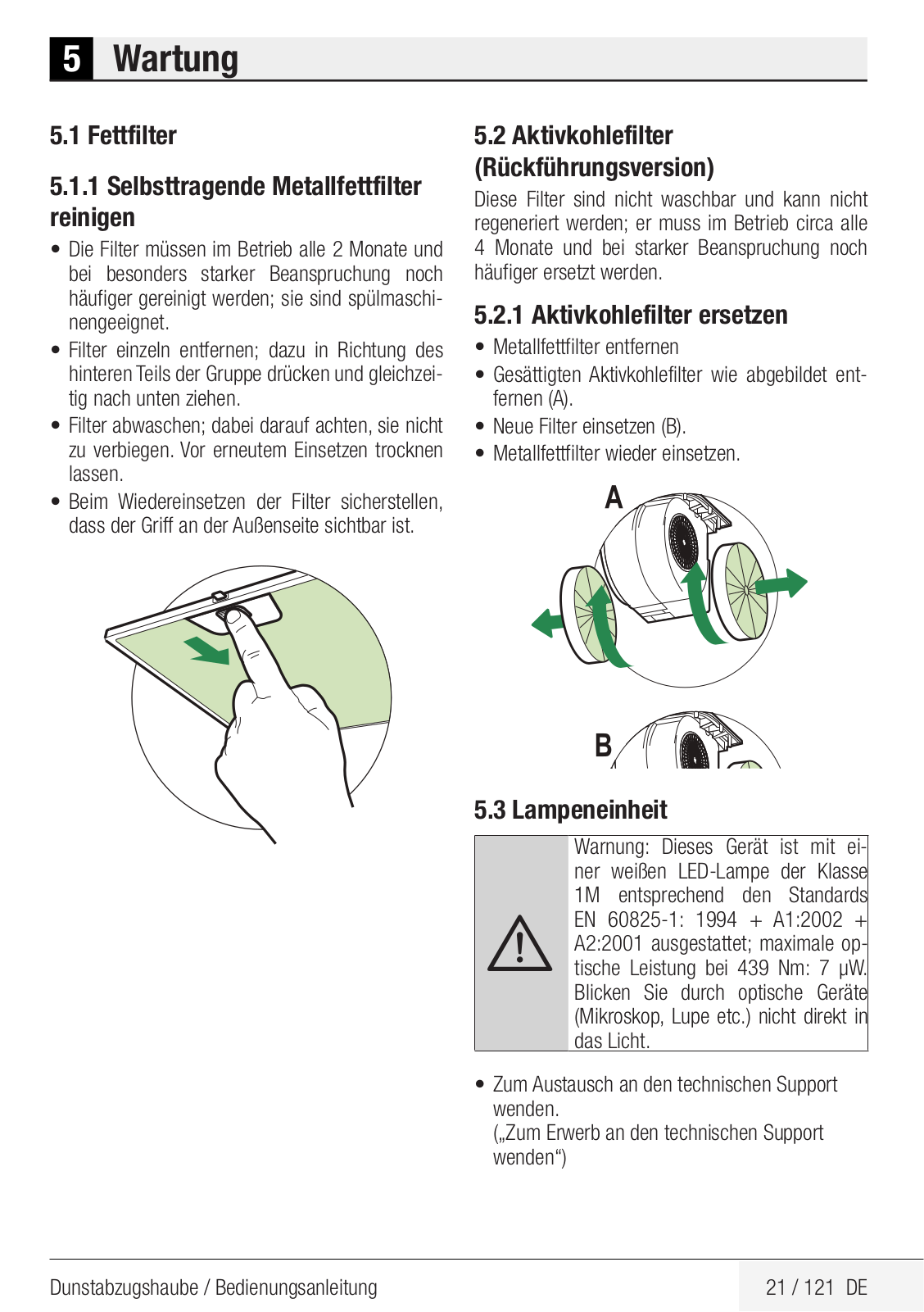
5
HCA63640B
6
HCA63640BH
8
HCA63640W
HCA63640Z
5
HCA91531X
2
HCA91731X
HCA91844XH
HCA92540B
3
HCA92640WH
3
HCA92741B
6
HCA92741BH
2
HCA92741W
4
HCA92844BH
4
HCA92844WH
3
HCA93640BH
8
HCA93641BH
4
HCA93641WH
HCAW64225SX
HCB19173BX
2
HCB61630BX
5
HCB61630BXH
2
HCB61731BX
5
HCB61731BXH
2
HCB61734BX
6
HCB61734BXH
5
HCB6173BXH
HCB62741BGH
3
HCB62741BWH
3
HCB62741BZH
4
HCB63741BX
5
HCB63741BXH
4
HCB 63744 BXH
HCB91630BX
4
HCB91630BXH
2
HCB91731BX
4
HCB91731BXH
4
HCB91734BX
5
HCB 91736 BX
2
HCB91845BDXH
2
HCB91845BX
4
HCB 91845 BXH
4
HCB91847BXHI
HCB93041XB
HCB93042X
HCB93741BX
6
HCB93741BXH
3
HCB93744BX
6
HCB93845BXH
6
HCB93847BXHI
2
HCB98744AH
HCC64103
2
HCF61531X
2
HCF61620X
4
HCF 91531 X
2
HCF91620X
2
HCG 61531 X
HCG61620X
3
HCG 91531 X
2
HCG91710X
HCG92741B
HCI91845BXH
12
HCI93847BXHI
HCMW64225SX
HCP 61310 B
HCP61310I
8
HCP61310IH
5
HCP 61310 W
9
HCP 61310 X
2
HCP91030X
HCP91310I
4
HCP 91310 IH
2
HCP 91310 W
3
HDB 30200 X
HDC
HDC32200X
HDCC32200
13
HDCC32200X
20
HDCC62200
HDCE 32200
6
HDCE 32200 X
13
HDCE 32201
7
HDCE 32201 X
12
HDCG 32200FX
HDCG 32220 F
11
HDCG 32220 FX
21
HDCG 32220 SX
2
HDCG32221F
6
HDCG32221FX
6
HDCG 32221 FX NL
2
HDCS32220F
5
HDCS 32220 FX
HDE32200W
HDF 7412 CSRX
HDF7434CSRX
2
HDG32210
3
HDG32210S
HDG 32210 SW
2
HDG 32210 W
2
HDMC 32200
Loading...
Loading...
Nothing found
HCB98744AH
User manual
124 pgs
12.17 Mb
0
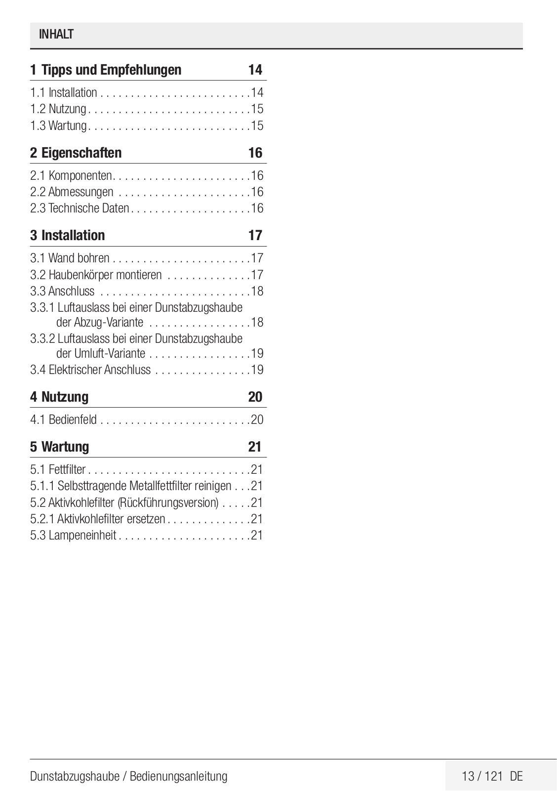
Table of contents
Loading...
Beko HCB98744AH User manual
...
Beko User manual
Download
Specifications and Main Features
Frequently Asked Questions
User Manual
Download
Loading...
+
94
hidden pages
Unhide
You need points to download manuals.
1 point = 1 manual.
You can buy points or you can get point for every manual you upload.
Buy points
Upload your manuals
 Loading...