

Page 1

LC CHASSIS
TFT- LCD TV SERVICE MANUAL
Page 2

CONTENTS
PAGES
Safety instructions
Technical specifications
Power rating and Panel Specifications
Remote control explanations
Service Menu of the TV
Set appearrances
Block diagram of the VCTI
Block diagram of Microcontroller (Genesis)
Block diagram of power supply
Data sheet of important IC’s
1
2
3
4
5
9
10
11
12
14
Service mode items and explanations
Replacement part List
Frequency list of channels
12
23
28
Page 3

SAFETY PRECAUTIONS
GENERAL GUIDELINES
1. Always use the manufacturer’s replacement safety
components. The critical safety components marked
with on the schematics diagrams should not be
by other substitutes. Other substitute may create the
electrical shock , fire or other hazards. Take
attention to replace the spacers with the originals.
Furthermore where a short circuit has occurred ,
replace those components that indicate evidence of
overheating.
2. After servicing , see that all the protective devices
such as insulation barriers, insulation papers, shields
and isolation R-C combinations are correctly
installed.
3. When the receiver is not being used for a long time
of period of time , unplug the power cord of the
Adaptor from the AC outlet.
Color TFT LCD Module is very sensitive
both electrically and physically.Users,
therefore, are requested to follow the
“Guidance of handling color TFT LCD
Module”on the followings.
1 - Be careful not to make scratch on the
polarizer.
Surface of polarizer is soft and can be physically
damaged easily.
Please do not touch, push or rub polarizer surface
with materials over HB hardness.
2 - Keep clean the surface.
Please wear rubber glove when touch the surface of
LCD screen. Please use so ft and anti-static material
as cleaner.
3 - Keep out of water.
Water on/in the LCD may cause electrical short or
corrosion. Please wipe out dry or water carefully.
4 - Prevent swift Temperature &
Humidity change.
Instantaneous temperature and/or humidity change
can make dew or ice which cause nonconformance
such as malfunction.
5 High temperature & high humidity
reduce the life-time.
LCD is not proper to be used at high temperature
and high humidity. Please keep specified
temperature and humidity condition.
6 - Keep out of Corrosive Gas.
Corrosive gas effect the polarizer and the circuit
chemically and cause defects accordingly.
7 - Electrostatic discharge can make
Damage
There are electro-static sensitive components such
as CMOS in LCD Module. Please earth human
body when handle the LCD.In addition, please do
not touch the interface connector pin with bare.
8 - Do not operate for a long time under
the same pattern
Operating LCD for a long time under the same
pattern can cause image persistence and can
damage it. Please follow following guidance.
1. Turn the power off when do not use.
2. Change the pattern periodically.
Page 4

SPECIFICATIONS
Receiving System PAL B/G+I+D/K SECAM L/L'
Tuning System PLL FST
Comb Filter Adaptive 4H\2H
LTI, CTI Filters Optional
Sync On Green (SOG) support on graphics YES
Scaling Upto SXGA at 75Hz
Stereo Decoding (German A2, Nicam, BTSC) German A2, Nicam
Virtual Dolby Optional
Subwoofer Optional
YPbPr In (Progressive) Through D-sub 15 conn. Optional
Number of speakers 2 (L+R)
Level (1.5, 2.5, Teleweb) Teletext 1.5
No Text- Optional
Teletext
Supported Menu Languages
Type
List Mode Optional
Page Memory 10p
ENGLISH, DEUTSCH, DUTCH, FRANCAIS,
ESPAÑOL, ITALIANO, PORTUGUESA,
EHΛΛNIKA, SVENSKA, NORSK, SUOMI,
TÜRKÇE, POLSKI, MAGYAR, ČEŠTINA,
ROMANESTE, SLOVENČINA, DANSK,
SERBIAN, PЧCCKИЙ, Bulgarian, Crotian
Fast Text -Optional
Top Text&Fast-Default
>> 22 Languages
4:3 YES
16:9
14:9
Picture Formats
(4:3, 16:9, 14:9, Panorama, LetterBox, Subtitle)
WSS (Wide Screen Signalling) Optional
ATS (Automatic Tuning System) Frequency Search
Manual Search Frequency Search
AFT (Auto Fine Tuning) YES
Number of Program Storage 100
No Ident Timer YES
Equalizer YES
AVL (Automatic Volume Level) YES
Sound Status Memory YES
Picture Status Memory YES
Zapping\Swap Optional
Panel Lock YES
Picture Format Switching Through Scart (Pin 8) YES
Auto RGB Detect Through Scart (Pin 16) YES
Timer On\Off or Sleep Optional
Picture Smart Modes YES
Sound Smart Modes YES
Simple Hotel Mode Optional
Wake Up in PC
Panorama NO
Letterbox
Subtitle
Zoom NO
Stby to On in PC mode
when last watched is PC
Stby to On automatically
when PC signal is available
4:3 Panels: Depends on LCD
16:9 Panels: YES
4:3 Panels: NO
16: 9 Panels: Depends on LCD
4:3 Panels: NO
16: 9 Panels: Depends on LCD
4:3 Panels: NO
16: 9 Panels: Depends on LCD
Optional
Optional
Memory Card Reader Optional
Page 5

p
z
(
POWER RATING AND PANEL SPECIFICATION
15" 17" 20" 22W" 26" 27" 32"
Adaptor Input
Current rating
Power consumptions
St-By Power
Consum
Input Range
Audio Output Power
%10) THD
Manufacturer
Interface
Resolution
Brightness (cd/m2)>
Contrast>
tion
12V 12V 15V 24V Built-in Power Built-in Power Built-in Power
3A 4A 4A 3A
48W 60W 75W 100W 130W 130W 130W
<3W <3W <3W <3W <3W <3W <3W
100-240V/50, 60Hz 100-240V/50, 60Hz 100-240V/50, 60Hz 100-240V/50, 60H
2X2W 2X3W 2X3W 2X7W 2X7W 2X7W
Samsung
CMO
AUO
Double TTL\Single
LVDS
XGA (1024x768)
250 300 500 450 450 550 550
300 400 500 500 400 600 600
Samsung CMO AUO Samsung
Dual LVDS
SXGA
(1280x1024)
Single TTL\Single
LVDS
SVGA (800x600)
VGA (640x480)
Single LVDS Singlel LVDS Singel LVDS Singel LVDS
WXGA
(1280x720)
100-240V/50, 60Hz 100-240V/50, 60H100-240V/50, 60Hz
Samsung
LG-Philips
AUO
WXGA (1280x768)
Chimei Chimei
WXGA
(1280x720)
WXGA (1280x720)
Page 6

11
12
13
14
15
16
10
REMOTE CONTROL
1.Picture Format ( )
1
2
123
3
4
5
6
7
8
9
456
789
AV
TXT/MIX
VOL+
‹
X
0
PC TV
OK
VOL-
?
SWAP
MENU
PR-
PR+
17
18
19
20
21
22
23
24
25
26
27
28
29
30
31
2. Temporary mute of volume (MUTE) (
3.Numeric buttons
4. Audio/Video (AV) (
5.PC mode transition (
)
)
6. Teletext / MIX / TV choice buttons (
7. Up (Menu -Teletext) (
8. Left (Menu) (
9. Volume UP (
)
)
10. Volume DOWN (
)
)
11. Red Fastext Button
12. Green Fastext Button
13. Index Button (P100) (
)
14. Question/Answer button (REVEAL) (
15. UPDATE Button (
16. SUB PAGE Button (
17. STAND-BY Button (
)
)
)
18. Return to Selected Program Button (SWAP) (
19. TV mode transition button (
20. Menu Button (
21. OK Button (
22. Right (Menu) (
)
)
)
23. Down (Menu/Teletext) (
24. Program up button (P+) (
25. Program down button (P-) (
)
)
)
)
26. Blue Fastext Button
27. Yellow Fastext Button
28. STOP Button (
)
29. Teletext enlarge button (DOUBLE) (
30. Equalizer selection button (
31. Picture control button (
)
)
)
)
)
)
)
Page 7

SERVICE MENU OF THE TV
DEFAULT VALUES OR
ITEM NAME
OPTIONS/ VALUES
OPTIONS
SCART 2 ON/OFF OFF
FAV ON/OFF ON
SVHS ON/OFF ON
HOTEL MODE ON/OFF OFF
STBY RECALL ON/OFF OFF
RECALL LAST AV ON/OFF OFF
MSP CARRIER MUTE ON/OFF OFF
WSS RF ON/OFF ON
AUTO AV 16:9 ON/OFF ON
FIRST ATS ON/OFF OFF
BACKLIGHT POL ON/OFF OFF
FACTORY MODE ON/OFF OFF
ADJUSTMENTS
SETUP
WHITE R 0-255 128
WHITE G 0-255 128
WHITE B 0-255 128
BRIGHTNESS 0-255 130
CONTRAST 0-257 158
COLOR 0-255 128
PRESCALE FM 0-127 37
PRESCALE NICAM 0-127 63
PRESCALE SCART 0-127 27
HOTEL VOLUME 0-63 16
AGC 0-31 23
FACTORY RESET
SW DOWNLOAD
SELECTIONS
TUNER TYPE
TELETEXT
PHILIPS , SAMSUNG
FAST&TOP , NO TEXT ,FAST
PHILIPS
FAST&TOP
TIMER MODE
MSP CLIP
SWAP/ZAPP
DOLBY VIRTUEL
SLEEP TIMER OFF TIMER
REDUCE VOL REDUCE
VOLUME
ON/OFF OFF
SLEEP TIMER
REDUCE VOL
ZAPP
Page 8

LC (L5C) SERVICE MENU
Service Menu is entered by pressing 9, 3, 0, 1 keys on the remote controller when the Picture icon is
highlighted in the Main Menu.
Service Menu has 3 sub-menus. These are:
• Options
• Adjustments
• Selections.
Navigation through these menus can be done by pressing OK button. Every adjustment made in this
menu is saved automatically.
OPTIONS
Options are adjustments that the user can select On or Off.
• SCART 2
• FAV
• SVHS
• HOTEL MODE
• STAND BY
• MSP CARRIER MUTE
• WSS SCART
• FIRST ATS
SCART 2 / FAV / SVHS
If a source is disabled in the Service Menu, it will be skipped during source switches. If SCART2 is
enabled, SW assumes that the FAV source share the same path as the SVHS source on the HW. If it is
disabled, it is assumed that FAV and SVHS share separate paths. TUNER and SCART1 are enabled by
default.
HOTEL MODE
Enabling Hotel Mode has two effects. First, SETUP menu is no longer accessible by the user. Second,
maximum adjustable volume value is limited to HOTEL VOLUME value. This value can be adjusted in the
ADJUSTMENTS sub-menu of the Service Menu.
STAND BY
If this Option is OFF, the TV will stay in Stand By mode after a Power On. If this Option is ON, the TV will
recall its last stand by status before the Power Off, and switch on from Stand By automatically, if the last
state was ‘Stand by On’.
MSP CARRIER MUTE
If this option is ON, sound processor’s carrier mute functionality will be enabled. The MSP will mute the
sound automatically if the signal quality is bad. Setting this option Off will disable this functionality.
ATS
If this option is set to ON, TV will display Country Selection menu in the next start. After some country is
selected, the user will be prompted for the start of AutoProgramming process.
Page 9

ADJUSTMENTS
This sub-menu contains numeric adjustments. These items are:
• WHITE R
• WHITE G
• WHITE B
• BRIGHTNESS
• CONTRAST
• COLOR
• PRESCALE FM
• PRESCALE NICAM
• PRESCALE SCART
• HOTEL VOLUME
WHITE R / WHITE G / WHITE B
These are used for color bias adjustment. Unlike other items in the service menu, changes will take effect
immediately.
PRESCALE FM / PRESCALE NICAM / PRESCALE SCART
These are prescale values that will be used for the initialization of the sound processor (MSP), at the next
switch on.
HOTEL VOLUME
This value is used as the volume limit, when the Hotel Mode is on.
SELECTIONS
This sub-menu contains selections.
• TUNER TYPE SAMSUNG / PHILIPS
• TELETEXT NO TEXT / FAST / FAST&TOP
• MSP CLIP REDUCE VOL / REDUCE TONE
TUNER TYPE
One of two supported tuner can be selected from this item. System must be restarted for this change to
take effect.
TELETEXT
NO TEXT: Teletext is totally disabled. TXT/MIX button will not be functional. AUTO picture format mode
will be disabled in RF, F-AV and SHVS modes. Naming and sorting functionality during Autoprogramming
will be disabled.
FAST: TOPtext functionality will be disabled.
FAST&TOP: TOPtext functionality is enabled.
TIMER MODE
If OFF TIMER is selected, the user will be able to enter time of the day info for the TV to switch off. If
SLEEP TIMER is selected, the user can specify some time period, after which the TV will go to stand by
automatically.
Page 10

MSP CLIP
This selection identifies which method will be used by the sound processor to prevent clipping effects on
volume.
AUTOPROGRAMMING
When the user selects the Autoprogram item in Setup menu, Country Selection menu is opened. The user
must select a country before the Autoprogramming starts. Broadcast system will be selected according to
the country selected.
Broadcast systems according to countries:
BELGIUM BG + L
CROATIA BG
CZECH REP. DK
DENMARK BG
FINLAND BG
FRANCE L + BG
GERMANY BG
GREECE BG
HUNGARY DK
IRELAND I
ITALY BG
NETHERLANDS BG
NORWAY BG
POLAND DK
PORTUGAL BG
SPAIN BG
SWEDEN BG
SWITZERLAND BG + L
TURKEY BG
UNITED KINGDOM I
For countries France, Belgium and Switzerland, autoprogramming is done twice. For Belgium and
Switzerland, first BG channels will be searched, after the search in BG is done, searching will restart for L
standard. If the selected country is France, the sequence of standards is reversed, thus, first L then BG.
TELETEXT LANGUAGES
L5C SW decides which teletext language group will be used for teletext decoding, according to the
country selected for autoprogramming.Teletext languages according to countries:
EAST EUROPE:CROATIA ,CZECH_REP, POLAND
WEST EUROPE: BELGIUM ,DENMARK, FINLAND, UK, FRANCE, GERMANY,
IRELAND ,ITALY ,NETHERLANDS, NORWAY, PORTUGAL,SPAIN, SWEDEN, SWITZERLAND,
HUNGARY
TURKISH-GREEK:GREECE TURKEY
PC MODE
PC mode can be entered by pressing PC button on the remote controller. User can return back to TV
mode by pressing the PC or TV buttons.
After the switching to PC mode, VGA input will be displayed on screen, as soon as the mode (input
resolution and frequency) is determined.
If there is no input from the VGA input, NO SIGNAL dialog will be displayed for 15 seconds. At the end of
this period if there is no signal from VGA input, the TV will go to Sleep State. While in the sleep state, the
TV will keep monitoring the VGA input. If VGA signal is detected, the TV will wake from Sleep State, to PC
mode. Alternatively, the user may select to switch the TV on from Sleep State, just like switching on from
Stand-by. In this case, the set will switch on from TV mode.
Page 11

SET APPEARANCE OF 26-32 INCH
Back light module
(Built-in Panel)
Back light module
Main
Chassis
Audio Amplifier
SET APPEARANCE OF 15-23 INCH
Main
Chassis
Power Supply board
Page 12
MULTISYSTEM
TUNER
SCART 1
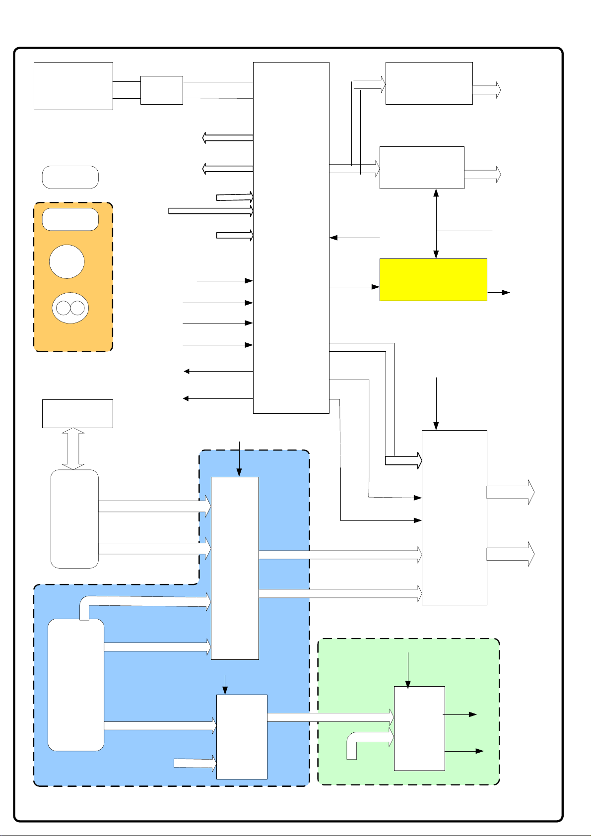
BLOCK DIAGRAM OF VCTI AND PERIPHERALS
SAW
FILTER
SC1-AUDIO-OUT
SC2-AUDIO-OUT
SC1 AUDIO-IN
IF INPUT
VCTI IC
PSS DIP88
U303
Aout1 R/L
Aout2 R/L
Ain2 L/R
L/R OUT
HEADPHONE
AMPL.TDA1308
AUDIO AMPL.
MAX9704
HEADPHONE
JACK
SPEAKERS
SCART 2
CVBS
RCA-IN
SVHS IN
OPTIONAL
EEPROM
24LC02
RGB-DSUB
RGB-IN
SC1-CVBS-IN
SC2-CVBS-IN
SVHS-C/Y IN
RCA-CVBS-IN
SC1-CVBS-OUT
SC2-CVBS-OUT
Ain1 L/R
PC-SD-SW
RESET Q
SUBWOOF.
HS-VCT
VS-VCT
MUTE
SUBWOOFER AMP.
MP7731
OPTIONAL
VCT-RGB-OUT
S1-MAIN-SW
2nd RGB
SWITCH
PI3V512
SUBWOOFER
SPEAKER
RGB-G
VGA
SOCKET
MEMORY
CARD
HS/VS-DSUB
RGB
RGB-SW
SWITCH
PI3V512
HS/VS-SW
RGB-SD
HS/VS-SD
MEMORY CARD
RCA SWITCH
AUDIO-R/L
MEMORY CARD
CD4053
MR-R/L
AUDIO
AUDIO-R/L-RCA
SWITCH
AUDIO-R/L-SC2
OPTIONAL OPTIONAL
RCA-S2SWITCH
CD4053
AUDIO
SWITCH
HS/VS-G
Ain1R
Ain1L
Page 13

BLOCK DIAGRAM OF GENESIS IC AND PERIPHERALS
U201 EEPROM
24LC16
RESET Q
RGB-G
HS/VS-G
IR INPUT
KEYBOARD
24 BIT RGB OUTPUT
TO LVDS INTERFACE
HS/VS
PANEL CTRL
DE
CLOCK
PANEL EN
MEMORY CARD-RCA SW
RCA-S2-SW
S1-MAIN-SW
U203
SERIAL FLASH
25VF040
SCART1 PIN 8
SCART2 PIN 8
STANDBY
STANDBY 2
MUTE
U200 GM5221-1 GENESIS LCD TV CONTROLLER
PC-SD-SW
LED
LED 2
BACKLIGHT-EN
BRT-ADJ.
UART RX/TX
PANEL PWR
BACK LIGHT
CONNECTOR
S202 SW
UPDATE CONN.
Page 14

BLOCK DIAGRAM OF 14-23 INCH POWER SUPPLY
OPTIONAL FOR 14"-17"-20"
S600
S601
15"-17" 12V
20" 15V
OPTIONAL FOR 20"W- 22"-23"
S603
S602
4
3
2
1
2 1
1 2 3 4 5 6 7
24V
GND
F600
FUSE 5A
GND
F601
FUSE 5A
INV_POW
AMP_POW
INV_POW
SUB_POW
AMP_POW
U602 MP1593
STEP DOWN
CONVERTOR
12V
(15V)
U605
MC78L08
U600 MP1593
STEP DOWN
CONVERTOR
Tuner Supply
VOLTAGE
DOUBLER
33V For Tuner
5V_STBY
PNL_EN
STBY
U603 LM1117
U601 LM1117
U604
SI9933
MOSFET
POWER
SWITCH
1.8V STBY
3.3V STBY
PANEL POWER
5V
8V
U606
LM1117
3.3V
Page 15

24V
GND
GND
12V
Stand-by 2
S101
1
2
3
4
5
6
7
8
9
10
JP100
1
2
3
4
5
6
7
BLOCK DIAGRAM OF 26 - 32 INCH POWER SUPPLY
12V-- R101 150K R609 220K R102 10K
INV_POW
AMP_POW_S
24V
12V
5V-- R101 56K R609 NI R102 18K
U600 MP1593
STEP DOWN
CONVERTOR
U100 MP1593
STEP DOWN
CONVERTOR
U101 MC34063
STEP-UP
CONVERTOR
U605 MC78L08
PNL_PWR
Enable
5V _ STBY
33V For
Tuner
8V
AMP_POW_S
STBY
U604
SI9933
MOSFET
POWER
SWITCH
U601 LM1117
U603 LM1117
AMP_POW
5V
3V3_STBY
1V8_STBY
3V3
U606 LM1117
Page 16

GENESIS GM5221 LCD TV CONTROLLER
The gm5221 is an LCD TV controller supporting resolutions up to SXGA (1280x1024). The gm5221
leverages Genesis patented advanced image-processing technology as well as a proven integrated
ADC/PLL and an Ultra-Reliable DVI™ compliant digital receiver to provide excellent image quality.
gm5221 also integrates a microcontroller, an OSD controller, advanced color management and dual
LVDS transmitters.
1.1 gm5221 System Design Example
Figure 1 below shows a typical dual interface LCD TV system based on the gm5221. Designs based on
the gm5221 have reduced system cost, simplified hardware and firmware design and increased reliability
because only a minimal number of components are required in the system.
C
V
B
S
S
V
I
D
E
O
Y
Pb
Pr
V
G
A
D
V
I
TUNER
PACK
VIDEO
DECODER
V CHIP
M
U
X
AUDIO
PROCESSOR
IR
KEY BOARD
gm5221
EEPROM
AUDIO
AMPL
L
C
D
D
I
S
P
L
A
Y
Figure 1. gm5221 System Design Example
Page 17

1.2 gm5221 Family Features
• Intelligent Image Processing™
• Fully programmable zoom ratios
• High-quality shrink capability from UXGA resolution
• Programmable coefficients for variable sharpness control
• RealRecovery™ provides full color recovery image for
refresh rates higher than those supported by the LCD panel
• Analog RGB Input Port
• Supports SDTV RGB inputs in interlaced mode
• Supports EDTV (480p) up to 1080i HDTV inputs
• Supports mid level clamp for YPbPr inputs
• Macro vision decoding
• Supports up to 162 MHz (SXGA 75Hz / UXGA 60Hz)
• On-chip high-performance PLLs (single reference crystal
required)
• Composite-sync, Sync-on-Green (SOG) and Sync-on-Y
(SoY) support
• Input format detection
• Phase and image positioning
• Ultra-Reliable DVI-Compliant Input Port
• Operating up to 165 MHz (up to UXGA 60Hz)
• Direct connect to all DVI 1.0-compliant transmitters
• High-bandwidth Digital Content Protection (HDCP)
Note: HDCP function is available H version only.
• CCIR-656 8-bit Video Input Port
• Supporting NTSC / PAL interlaced and progressive
• Direct connect to commercially available video decoders
• Spatial de-interlacing
• Advanced Color Management
• Programmable gamma correction (CLUT)
• TV color controls including hue and saturation controls
• Full color matrix allows end-users to experience the same
colors as viewed on CRTs and other displays (e.g. sRGB
compliance)
• Advanced Active Color Management ™ (ACM-II) provide
flesh-tone compensation and image enhancement for video
preset modes like sport, nature .
• Adaptive Contrast and Color™ (ACC) ensures full dynamic
range is used in video content
• Embedded X86 On-chip Microcontroller
• High-performance X86 MCU with on-chip RAM and ROM
• External parallel ROM or serial SPI ROM interface
• Unified memory architecture simplifies chip programming
• 23 general-purpose inputs/outputs (GPIOs) available
• 2-wire serial bus master to control NVRAM, video decoder
• Two DDC2Bi ports with DMA buffer to internal RAM
• Four PWM outputs for analog backlight control, audio, etc.
• General-purpose ADC’s for keypad and temperature sensing
• Integrated reset circuit
• Slow clock mode for 50mW sleep mode power consumption
• JTAG debug / ICE support for firmware debugging
• Built-in Test Pattern Generator
• Simplifies manufacturing / test
• Energy Spectrum Management (ESM™)
• Digital clock spectrum management
• Eliminates EMI suppression components and shielding
• Built-in LVDS Transmitters
• Four channel 6/8-bit LVDS transmitter
• Support for 8 or 6-bit panels with high-quality dithering
• Single / double wide up to SXGA 75Hz output
• Pin swap, odd / even swap and red / blue group swap of RGB
outputs for flexibility in board layout
• Highly integrated System-on-a-Chip
• All system clocks synthesized from a single external crystal
• 50mW power saving mode
• 5-Volt tolerant inputs
• Two Layer PCB support
• On-chip reset feature to eliminate external reset component
• Integrated Schmitt trigger for HSYNC and VSYNC
PACKAGE
• 208-pin PQFP
• 3.3V IO and 1.8V core power supplies
• On-chip Versatile OSD Controller
• On-chip RAM for high-quality programmable menus
• 1, 2 and 4-bit per pixel character cells
• Horizontal and vertical stretch of OSD menus
• Blinking, transparency and blending
• Supports two independent OSD menu rectangles
• Proportional fonts
Page 18

2 gm5221 Pinout
The gm5221 devices are packaged in a 208-pin Plastic Quad Flat Pack (PQFP).
ROM_DATA4
ROM_DATA5
CRVSS
RVDD_3.3
ROM_DATA6
ROM_DATA7
ROM_ADDR0
ROM_ADDR1
ROM_ADDR2
ROM_ADDR3
ROM_ADDR4
ROM_ADDR5
ROM_ADDR6
ROM_ADDR7
ROM_ADDR8
ROM_ADDR9
ROM_ADDR10
CRVSS
RVDD_3.3
ROM_ADDR11
ROM_ADDR12
ROM_ADDR13
ROM_ADDR14
ROM_ADDR15
ROM_ADDR16
ROM_ADDR17
VSYNC
HSYNC/CSYNC
CRVSS
CVDD_1.8
RESETn
LBADC_GND
LBADC_RETURN
LBADC_IN3
LBADC_IN2
LBADC_IN1
LBADC_VDD_3.3
AVDD_RPLL_3.3
TCLK
XTAL
AGND_RPLL
ROM_DATA3
ROM_DATA2
ROM_DATA1
ROM_DATA0
ROM_OEn
ROM_WEn
ROM_CSn
CRVSS
CVDD_1.8
RESERVED
AVDD_LV_E_3.3
AVSS_LV_E
CH3P_LV_E/ER0
CH3N_LV_E/ER1
CLKP_LV_E/ER2
CLKN_LV_E/ER3
CH2P_LV_E/ER4
CH2N_LV_E/ER5
CH1P_LV_E/ER6
CH1N_LV_E/ER7
CH0P_LV_E/EG0
CH0N_LV_E/EG1
AVSS_LV_E
AVDD_LV_E_3..3
AVSS_LV
AVDD_LV_3.3
AVDD_LV_O_3.3
AVSS_LV_O
CH3P_LV_O/EG2
CH3N_LV_O/EG3
CLKP_LV_O/EG4
CLKN_LV_O /EG5
CH2P_LV_O/EG6
CH2N_LV_O/EG7
CH1P_LV_O/EB0
CH1N_LV_O/EB1
CH0P_LV_O/EB2
CH0N_LV_O/EB3
AVSS_LV_O
AVDD_LV_O_3..3
CVDD_1..8
RVDD_3.3
CRVSS
CVSS
EB4
EB5
EB6
EB7
DEN
DHS
DVS
N/C
1
208
207
206
205
204
203
202
201
200
199
198
197
196
195
194
193
192
191
190
189
188
187
186
185
184
183
182
181
180
179
178
177
176
175
174
173
172
171
170
169
2
3
4
5
6
7
8
9
10
11
12
13
14
15
16
17
18
19
20
21
22
23
24
25
26
27
28
29
30
31
32
33
34
35
36
37
38
39
40
41
42
43
44
45
46
47
48
49
50
51
52
5354555657585960616263646566676869707172737475767778798081828384858687888990919293949596979899
N/C
N/C
DCLK
RESERVED
RESERVED
RESERVED
RESERVED
RESERVED
RESERVED
JTAG_RESET
RESERVED
JTAG_TDO
JTAG_TDI
RESERVED
PPWR
PBIAS
GPIO15
RESERVED
HOST_SCL/UART_DI
HOST_SDA/UART_DO
GPIO0
GPIO1
GPIO2
GPIO3
GPIO4
GPIO5
CRVSS
CRVSS
RVDD_3.3
CVDD_1.8
DDC_SCL_DVI
DDC_SDA_DVI
DDC_SCL_VGA
DDC_SDA_VGA
CRVSS
CVDD_1.8
168
GPIO6
GPIO9/SCL
GPIO7/IRQin
GPIO10/SDA
GPIO8/IRQout
RESERVED
VDD_RPLL_1.8
167
166
CRVSS
RVDD_3.3
GND_RPLL
165
CVDD_1.8
VDD_ADC_1.8
GND_ADC
164
163
CRVSS
N/C
N/C
N/C
N/C
N/C
N/C
AGND_ADC
162
161
100
GPIO11/PWM0
GPIO12/PWM1
156
160
159
158
157
RESERVED
155
AVDD_ADC_3.3
154
AGND_RED
153
RED-
152
RED+
151
AVDD_RED_3.3
150
AGND_GREEN
149
GREEN-
148
GREEN+
147
SOG_MCSS
146
AVDD_GREEN_3.3
145
AGND_BLUE
144
BLUE-
143
BLUE+
142
AVDD_BLUE_3.3
141
CRVSS
140
CVDD_1.8
139
RESERVED
138
VDD_RXPLL_1.8
137
GND_RXPLL
136
RESERVED
135
AVDD_RXC_3.3
134
RXC-
133
RXC+
132
AGND_RXC
131
AVDD_RX0_3.3
130
RX0-
129
RX0+
128
AGND_RX0
127
VDD_RX0_1.8
126
AVDD_RX1_3.3
125
RX1-
124
RX1+
123
AGND_RX1
122
VDD_RX1_1.8
121
AVDD_RX2_3.3
120
RX2-
119
RX2+
118
AGND_RX2
117
VDD_RX2_1.8
116
AGND_IMB
115
REXT
114
AVDD_IMB_3.3
113
VCLK
112
GPIO23/VDATA0
111
GPIO22/VDATA1
110
GPIO21/VDATA2
109
GPIO20/VDATA3
108
GPIO19/VDATA4
107
GPIO18/VDATA5
106
N/C
105
101
102
103
104
N/C
GPIO13/PWM2
GPIO14/PWM3
GPIO16/VDATA7
GPIO17/VDATA6
Figure 2. gm5221 Pin Out Diagram
Page 19

VCT49xxI
Volume 1: General Description
General Description
1. Introduction
The VCT 49xxI is an IC family of high-quality singlechip TV processors. Modular design and deep-submicron technology allow the economic integration of features in all classes of single-scan TV sets. The
VCT 49xxI family is based on functional blocks contained and approved in existing products like
DRX 396xA, MSP 34x5G, VSP 94x7B, DDP 3315C,
and SDA 55xx.
Each member of the family contains the entire IF,
audio, video, display, and deflection processing for 4:3
and 16:9 50/60-Hz mono and stereo TV sets. The integrated microcontroller is supported by a powerful OSD
generator with integrated Teletext & CC acquisition
including on-chip page memory.
Video & Sound IF
DRX 396xA
Audio Processing
MSP 34x5G
1.1. Features
The VCT 49xxI family offers a rich feature set, covering the whole range of state-of-the-art 50/60-Hz TV
applications.
– PSSDIP88-1/-2 package
– Submicron CMOS technology
– Low-power standby mode
– Single 20.25-MHz reference crystal
– 8-bit 8051 instruction set compatible CPU
– Up to 256 kB on-chip program ROM
– WST,PDC,VPS,andWSSacquisition
– ClosedCaptionandV-chipacquisition
– Up to 10 pages on-chip teletext memory
– Multi-standard QSS IF processing with single SAW
– FM Radio and RDS with standard TV tuner
– TV-sound demodulation:
• all A2 standards
• all NICAM standards
• BTSC/SAP with MNR (DBX optional)
•EIA-J
Video Processing
VSP 94x7B
Display & Deflection
DDP 3315C
Control, OSD, Text
SDA 55xx
Fig. 1–1: Single-chip VCT 49xxI
VCT 49xyI
– Baseband sound processing for loudspeaker chan-
nel:
• volume
• bass and treble
• loudness
• balance
• spatial effect (e.g. pseudo stereo)
• Micronas AROUND (virtual Dolby optional)
• Micronas BASS
– CVBS, S-VHS, YC
and RGB inputs
rCb
– 4H adaptive comb filter (PAL/NTSC)
– multi-standard color decoder (PAL/NTSC/SECAM)
– Nonlinear horizontal scaling “panorama vision”
– Luma and chroma transient improvement (LTI, CTI)
– Non-linear color space enhancement (NCE)
– Dynamic black level expander (BLE)
– Scan velocity modulation output
– Soft start/stop of H-drive
– Vertical angle and bow correction
– Average and peak beam current limiter
– Nonlinear and dynamic EHT compensation
– Black switch off procedure (BSO)
Page 20

R
PSSDIP88-2 package
E
K
C
G
F
I
A
T
S
T
A
U
E
N
O
I
P
A
S
A
IFIN+
IFIN-
CVBS in
YCrCb in
RGB in
CVBS out
IF
Frontend
Video
Frontend
Slicer
24kB
Char ROM
20kB XRAM
IF
Processor
Comb
Filter
Component
Bus
Arbiter
256kB
Prog ROM
Interface
Sound
Demodulator
Color
Decoder
Display
Generator
Memory
Interface
CPU
8051
Panorama
Scaler
Audio
Processor
Display &
Deflection
Processor
I2C Master/
Slave
Timer
CRT
PWM
ADC
UART
Watchdog
RTC
I/O-Ports
Video
Backend
Reset & Test
Logic
Clock
Generator
PROT
HOUT
HFLB
VERT
EW
SVM
RGB out
RGB in
SENSE
RSW
I2C
RESETQ
TEST
XTAL1
XTAL2
ADB, DB, PSENQ,
PSWEQ, WRQ, RDQ
Fig. 1–2: Block diagram of the VCT 49xxI
45
GND
P10
P11
P12
P13
P14
P15
P16
P17
SCL
SDA
HOUT
HFLB
GND
GND
XREF
VRD
BOUT
GOUT
ROUT
BIN
GIN
RIN
FBIN
RSW1
RSW2
EW
TEST
GND
46
47
48
49
50
51
52
53
54
55
56
57
58
59
60
61
62
63
64
65
66
67
68
69
70
71
72
73
74
75
76
77
78
79
80
81
82
83
84
85
86
87
88
VSUP3.3FE
P20 / DFVBL
P21 / PWMV
VPROT
SAFETY
GNDDAC
VSUP3.3DAC
VSUP3.3IO
VSUP3.3BE
SVMOUT
GNDM
SENSE
VERT-
VERT+
VSUP5.0BE
Pxy
44
GND
43
VSUP1.8FE
42
VOUT3
41
VOUT2
40
VOUT1
39
VIN1
38
VIN2
37
VIN3
36
VIN4
35
VIN5
34
VIN6
33
VIN7
32
VIN8
31
VIN9
30
VIN10
29
VIN11
28
P23
27
P22
26
XTAL2
25
XTAL1
24
VSUP1.8DIG
23
GND
22
GND
21
VSUP3.3DIG
20
VSUP5.0IF
19
GNDIF
18
RESETQ
17
IFIN+
16
IFIN-
15
VREFIF
14
VCT 49xyI
TAGC
13
SIF / AIN1R
12
AIN1L
11
AIN2R
10
AIN2L
9
AIN3R / AOUT2R
8
AIN3L / AOUT2L
7
AOUT1R
6
AOUT1L
5
SPEAKERR
4
SPEAKERL
3
VREFAU
2
VSUP8.0AU
1
GND
Page 21

Si9933ADY
Si9933ADY
Dual P-Channel PowerTrench MOSFET
January 200 1
General Description
This P-Channel MOSFET is a rugged gate version of
Fairchild Semiconductor’s advanced PowerTrench
process. It has been optimized for power management
applications with a wide range of gate drive voltage
Features
• –5 A, –20 V, R
R
R
= 75 m Ω @ VGS = –4.5 V
DS(ON)
= 105 m Ω @ VGS = –3.0 V
DS(ON)
= 115 mΩ @ VGS = –2.7 V
DS(ON)
(2.5V – 12V).
• Extended V
range (±12V) for battery applications
GSS
Applications
• Load switch
• Motor drive
• DC/DC conversion
• Power management
Absolute Maximum Ratings T
=25oC unless otherwise noted
A
• Low gate charge
• High performance trench technology for extremely
low R
DS(ON)
• High power and current handling capability
5
Q1
6
7
Q2
8
4
3
2
1
Symbol Parameter Ratings Units
V
DSS
V
GSS
I
D
P
D
TJ, T
STG
Drain-Source Voltage
Gate-Source Voltage
Drain Current – Continuous (Note 1a)
– Pulsed
Power Dissipation for Dual Operation 2
Power Dissipation for Single Operation (Note 1a) 1.6
(Note 1b)
(Note 1c)
Operating and Storage Junction Temperature Range –55 to +175 °C
–20
±12
–3.4
–16
1
0.9
V
V
A
W
Thermal Characteristics
R
θJA
R
θJC
Thermal Resistance, Junction-to-Ambient (Note 1a) 78 °C/W
Thermal Resistance, Junction-to-Case (Note 1) 40 °C/W
Package Marking and Ordering Information
Device Marking Device Reel Size Tape width Quantity
9933A Si9933ADY 13’’ 12mm 2500 units
2001 Fairchild Semiconductor International Si9933ADY Rev A(W)
Page 22

Monolithic Power Systems
MP1593
3A, 28V
Step Down Converter
PRELIMINARY
General Description
The MP1593 is a step-down regulator with an
internal Power MOSFET. It achieves 3A
continuous output current over a wide input
supply range with excellent load and line
regulation.
Current mode operation provides fast transient
response and eases loop stabilization.
Fault condition protection includes cycle-by-cycle
current limiting and thermal shutdown.
Adjustable soft-start reduces the stress on the
input source at turn-on. In shutdown mode the
regulator draws 20µA of supply current.
The MP1593 requires a minimum number of
readily available external components to
complete a 3A step down DC to DC converter
solution.
Ordering Information
Part Number ∗
MP1593DN
∗ For Tape & Reel use suffix - Z (e.g. MP1593DN-Z)
Package Temperature
SOIC8 w/ Exposed
Paddle
-40 to + 85°C
Features
3A Output Current
Programmable Soft-Start
100mΩ Internal Power MOSFET Switch
Stable with Low ESR Output Ceramic
Capacitors
Up to 95% Efficiency
20µA Shutdown Mode
Fixed 385KHz Frequency
Thermal Shutdown
Cycle-by-Cycle Over Current Protection
Wide 4.75 to 28V Operating Input
Range
Output Adjustable From 1.22
Under Voltage Lockout
Available in 8 pin SOIC Package
Applications
Distributed Power Systems
Battery Charger
Pre-Regulator for Linear Regulators
Typical Application Circuit
INPUT
4.75 to 28V
IN
EN
MP1593
SS
BS
SW
FB
COMPGND
OUTPUT
2.5V, 3A
Page 23

Monolithic Power Systems
Pin Description
MP1593
3A, 28V
Step Down Converter
PRELIMINARY
Exposed Pad on
Backside.
Connect to Pin 4.
BS 1
IN
SW
GND
2
3
4
Table 1: Pin Designators
# Name Description
1 BS
2 IN
3 SW
4 GND Ground. (Note: Connect the exposed pad on backside to Pin 4).
5 FB
6 COMP
7 EN
8 SS
High-Side Gate Drive Boost Input. BS supplies the drive for the high-side n-channel MOSFET
switch. Connect a 10nF or greater capacitor from SW to BS to power the high side switch.
Power Input. IN supplies the power to the IC, as well as the step-down converter switches.
Drive IN with a 4.75V to 28V power source. Bypass IN to GND with a suitably large capacitor
to eliminate noise on the input to the IC. See Input Capacitor section.
Power Switching Output. SW is the switching node that supplies power to the output.
Connect the output LC filter from SW to the output load. Note that a capacitor is required from
SW to BS to power the high-side switch.
Feedback Input. FB senses the output voltage to regulate that voltage. Drive FB with a
resistive voltage divider from the output voltage. The feedback threshold is 1.222V. See
Setting the Output Voltage section.
Compensation Node. COMP is used to compensate the regulation control loop. Connect a
series RC network from COMP to GND to compensate the regulation control loop. In some
cases, an additional capacitor from COMP to GND is required. See Compensation section.
Enable Input. EN is a digital input that turns the regulator on or off. Drive EN high to turn on
the regulator, drive EN low to turn it off. An Under Voltage Lockout (UVLO) function can be
implemented by the addition of a resistor divider from V
shutdown its needs to be less than 0.7V. For automatic startup, leave EN unconnected.
Soft Start Control Input. SS controls the soft start period. Connect a capacitor from SS to
GND to set the soft-start period. A 0.1µF capacitor sets the soft-start period to 10ms. To
disable the soft-start feature, leave SS unconnected.
to GND. For complete low current
IN
8
SS
7
EN
6
COMP
5
FB
Page 24

U
REPLACEMENT PART LIST
The components which are referred positions may changes by model, size, cosmetic and specification of the LCD TV.
Please apply web pages for current part list. The items marked with red are safety components or need to be replaced with
original/approved parts.
POS
X941 032150R HP JACK 17"LCD TV (OLD-8R9185) R217 172479R RC-CHIP 4.7K J 1/16W /0603 TAPE
X940 031224R CONN.HOUS.3P 2317-3S JST B 3B-XH-A WHITE R222 172479R RC-CHIP 4.7K J 1/16W /0603 TAPE
C940 273471R C-PEM 47NF K 63V R:5 R406 170474R RC-CHIP 47R J 1/16W /0603 TAPE
C941 273471R C-PEM 47NF K 63V R:5 R407 170474R RC-CHIP 47R J 1/16W /0603 TAPE
C639 252482R EC 470UF 16V 12.5*10 R:5 R410 170474R RC-CHIP 47R J 1/16W /0603 TAPE
U605 452904R IC LM78L08ACZ R411 170474R RC-CHIP 47R J 1/16W /0603 TAPE
Y300 056161R CRYSTAL 20.25MHZ HC49-U U402 458931R IC-CHIP PI3V512 RGB SW PERICOM
S300 031224R CONN.HOUS.3P 2317-3S JST B 3B-XH-A WHITE U402 450526R IC-CHIP PI3V512QEX (QSOP24)
S301 031251R SCART SOCKET 14.1 D301 303818R DIODE-CHIP BAV99LT1 SOT23 T&R
Y200 056119R CRYSTAL 14.31818MHz CL=18PF30/30PPMHC49
SW201 010844R TACT SWITCH 2 LEG (MTSB) Q201 401472R TRN-CHIP 2N7002 N-CHANNEL SOT23
J310 031163R KONN. CINCH ........ WHITE HOR.14.1 R363 170754R RC-CHIP 75R J 1/16W /0603
J309 031164R KONN. CINCH ........... RED HOR.14.1 R365 170754R RC-CHIP 75R J 1/16W /0603
L200 053352R COIL- CHOKE 10UH R0814 14.1 R366 170754R RC-CHIP 75R J 1/16W /0603
L202 053352R COIL- CHOKE 10UH R0814 14.1 R367 170754R RC-CHIP 75R J 1/16W /0603
L300 053352R COIL- CHOKE 10UH R0814 14.1 R368 170754R RC-CHIP 75R J 1/16W /0603
L301 053352R COIL- CHOKE 10UH R0814 14.1 R369 170754R RC-CHIP 75R J 1/16W /0603
L312 053352R COIL- CHOKE 10UH R0814 14.1 R415 170754R RC-CHIP 75R J 1/16W /0603
S204 031194R CONN.HOUS.4P 2317-4S JST B 4B-XH-A WHITE R416 170754R RC-CHIP 75R J 1/16W /0603
S202 031194R CONN.HOUS.4P 2317-4S JST B 4B-XH-A WHITE R417 170754R RC-CHIP 75R J 1/16W /0603
SAW300 056298R SAW FILTER X6966M C413 290223R CC-CHIP 22PF J 50V /0603 NPO TAPE
U303
U303
C629 253128R EC 1000UF 16V 20*10 R:5 LOW ESR R236 171107R RC-CHIP 100R J 1/16W /0603
P400 031358R CONN. VGA B10B R341 171107R RC-CHIP 100R J 1/16W /0603
R237 171250R RC-CHIP 249R F %1 / 0603 R342 171107R RC-CHIP 100R J 1/16W /0603
U201 452662R-2 IC-CHIP AT24C16AN 10SU2.7 TAPE&REEL R345 171107R RC-CHIP 100R J 1/16W /0603
U300 452706R-1 IC TDA1308T/N2 SO-G8 (T&R) R346 171107R RC-CHIP 100R J 1/16W /0603
U200 453296R IC-CHIP GM2221-LF-BC 208PIN PQFP TRAY R257 171107R RC-CHIP 100R J 1/16W /0603
R325 170225R RC-CHIP 22R J 1/10W /0603 R255 171107R RC-CHIP 100R J 1/16W /0603
C371 292114R CC-CHIP 1NF K 50V /0603 X7R R347 171107R RC-CHIP 100R J 1/16W /0603
C372 292114R CC-CHIP 1NF K 50V /0603 X7R R348 171107R RC-CHIP 100R J 1/16W /0603
C373 292114R CC-CHIP 1NF K 50V /0603 X7R R357 171107R RC-CHIP 100R J 1/16W /0603
C376 292114R CC-CHIP 1NF K 50V /0603 X7R R358 172104R RC-CHIP 1K J 1/16W /0603
C377 292114R CC-CHIP 1NF K 50V /0603 X7R R607 172104R RC-CHIP 1K J 1/16W /0603
C378 292114R CC-CHIP 1NF K 50V /0603 X7R R258 172104R RC-CHIP 1K J 1/16W /0603
C379 292114R CC-CHIP 1NF K 50V /0603 X7R R423 172104R RC-CHIP 1K J 1/16W /0603
C380 292114R CC-CHIP 1NF K 50V /0603 X7R R424 172104R RC-CHIP 1K J 1/16W /0603
C381 292114R CC-CHIP 1NF K 50V /0603 X7R R418 172104R RC-CHIP 1K J 1/16W /0603
C390 292114R CC-CHIP 1NF K 50V /0603 X7R R419 172104R RC-CHIP 1K J 1/16W /0603
C391 292114R CC-CHIP 1NF K 50V /0603 X7R C394 292153R CC-CHIP 1.5NF K 50V /0603 X7R TAPE
C392 292114R CC-CHIP 1NF K 50V /0603 X7R C395 292153R CC-CHIP 1.5NF K 50V /0603 X7R TAPE
C393 292114R CC-CHIP 1NF K 50V /0603 X7R R401 171336R RC-CHIP 330R J 1/16W /0603 TAPE
J304 179005R RC-CHIP 0R /0603 1.6*0.8 TAPE R402 171336R RC-CHIP 330R J 1/16W /0603 TAPE
J235 179005R RC-CHIP 0R /0603 1.6*0.8 TAPE R385 172513R RC-CHIP 5.1K J 1/16W /0603
J305 179005R RC-CHIP 0R /0603 1.6*0.8 TAPE R378 172567R RC-CHIP 5.6K J 1/16W /0603 TAPE
J314 179005R RC-CHIP 0R /0603 1.6*0.8 TAPE R379 172567R RC-CHIP 5.6K J 1/16W /0603 TAPE
R422 172686R RC-CHIP 6.8K J 1/16W /0603 C321 294125R CC-CHIP 100NF K 25V /0603 X7R
R398 173277R RC-CHIP 27K J 1/16W /0603 TAPE C446 294125R CC-CHIP 100NF K 25V /0603 X7R
PART
NUMBER
Y10184 H.PHONE MOD-PN LCD TV L5A CHASIS R213 172479R RC-CHIP 4.7K J 1/16W /0603 TAPE
Y10187R R/C L5A SASI KUMANDA KMK-01 SILVER R408 170474R RC-CHIP 47R J 1/16W /0603 TAPE
N1F110 LC SD-32W M/NX/2/K/SV/VGA/A-OSD/AU3 R409 170474R RC-CHIP 47R J 1/16W /0603 TAPE
S-SWVCTI01BG SW IC VCTI 5LC BEKO/GRUNDIG C414 290223R CC-CHIP 22PF J 50V /0603 NPO TAPE
S-SWVCTI01BGV SW IC VCTI 5LC BEKO/GRUNDIG VD R235 171107R RC-CHIP 100R J 1/16W /0603
PART DESCRIPTION POS
Q200 401472R TRN-CHIP 2N7002 N-CHANNEL SOT23
PART
NUMBER
PART DESCRIPTION
Page 25

POS
C200 294125R CC-CHIP 100NF K 25V /0603 X7R C448 294125R CC-CHIP 100NF K 25V /0603 X7R
C201 294125R CC-CHIP 100NF K 25V /0603 X7R C449 294125R CC-CHIP 100NF K 25V /0603 X7R
C202 294125R CC-CHIP 100NF K 25V /0603 X7R C450 294125R CC-CHIP 100NF K 25V /0603 X7R
C203 294125R CC-CHIP 100NF K 25V /0603 X7R C451 294125R CC-CHIP 100NF K 25V /0603 X7R
C204 294125R CC-CHIP 100NF K 25V /0603 X7R C456 294125R CC-CHIP 100NF K 25V /0603 X7R
C205 294125R CC-CHIP 100NF K 25V /0603 X7R C609 294125R CC-CHIP 100NF K 25V /0603 X7R
C206 294125R CC-CHIP 100NF K 25V /0603 X7R C610 294125R CC-CHIP 100NF K 25V /0603 X7R
C207 294125R CC-CHIP 100NF K 25V /0603 X7R C615 294125R CC-CHIP 100NF K 25V /0603 X7R
C208 294125R CC-CHIP 100NF K 25V /0603 X7R C616 294125R CC-CHIP 100NF K 25V /0603 X7R
C228 294125R CC-CHIP 100NF K 25V /0603 X7R C617 294125R CC-CHIP 100NF K 25V /0603 X7R
C229 294125R CC-CHIP 100NF K 25V /0603 X7R C619 294125R CC-CHIP 100NF K 25V /0603 X7R
C230 294125R CC-CHIP 100NF K 25V /0603 X7R C620 294125R CC-CHIP 100NF K 25V /0603 X7R
C231 294125R CC-CHIP 100NF K 25V /0603 X7R C621 294125R CC-CHIP 100NF K 25V /0603 X7R
C232 294125R CC-CHIP 100NF K 25V /0603 X7R C622 294125R CC-CHIP 100NF K 25V /0603 X7R
C233 294125R CC-CHIP 100NF K 25V /0603 X7R C623 294125R CC-CHIP 100NF K 25V /0603 X7R
C234 294125R CC-CHIP 100NF K 25V /0603 X7R C624 294125R CC-CHIP 100NF K 25V /0603 X7R
C235 294125R CC-CHIP 100NF K 25V /0603 X7R C316 294125R CC-CHIP 100NF K 25V /0603 X7R
C236 294125R CC-CHIP 100NF K 25V /0603 X7R C327 294125R CC-CHIP 100NF K 25V /0603 X7R
C237 294125R CC-CHIP 100NF K 25V /0603 X7R C242 294125R CC-CHIP 100NF K 25V /0603 X7R
C238 294125R CC-CHIP 100NF K 25V /0603 X7R C311 294125R CC-CHIP 100NF K 25V /0603 X7R
C239 294125R CC-CHIP 100NF K 25V /0603 X7R C312 294125R CC-CHIP 100NF K 25V /0603 X7R
C300 294125R CC-CHIP 100NF K 25V /0603 X7R R200 173100R RC-CHIP 10K J 1/10W /0603
C301 294125R CC-CHIP 100NF K 25V /0603 X7R R201 173100R RC-CHIP 10K J 1/10W /0603
C302 294125R CC-CHIP 100NF K 25V /0603 X7R R202 173100R RC-CHIP 10K J 1/10W /0603
C303 294125R CC-CHIP 100NF K 25V /0603 X7R R203 173100R RC-CHIP 10K J 1/10W /0603
C304 294125R CC-CHIP 100NF K 25V /0603 X7R R243 173100R RC-CHIP 10K J 1/10W /0603
C305 294125R CC-CHIP 100NF K 25V /0603 X7R R245 173100R RC-CHIP 10K J 1/10W /0603
C306 294125R CC-CHIP 100NF K 25V /0603 X7R R300 173100R RC-CHIP 10K J 1/10W /0603
C307 294125R CC-CHIP 100NF K 25V /0603 X7R R302 173100R RC-CHIP 10K J 1/10W /0603
C308 294125R CC-CHIP 100NF K 25V /0603 X7R R304 173100R RC-CHIP 10K J 1/10W /0603
C309 294125R CC-CHIP 100NF K 25V /0603 X7R R322 173100R RC-CHIP 10K J 1/10W /0603
C310 294125R CC-CHIP 100NF K 25V /0603 X7R R323 173100R RC-CHIP 10K J 1/10W /0603
C313 294125R CC-CHIP 100NF K 25V /0603 X7R R334 173100R RC-CHIP 10K J 1/10W /0603
C314 294125R CC-CHIP 100NF K 25V /0603 X7R R604 173100R RC-CHIP 10K J 1/10W /0603
C315 294125R CC-CHIP 100NF K 25V /0603 X7R R247 173100R RC-CHIP 10K J 1/10W /0603
C317 294125R CC-CHIP 100NF K 25V /0603 X7R R248 173100R RC-CHIP 10K J 1/10W /0603
C318 294125R CC-CHIP 100NF K 25V /0603 X7R R249 173100R RC-CHIP 10K J 1/10W /0603
C319 294125R CC-CHIP 100NF K 25V /0603 X7R R250 173100R RC-CHIP 10K J 1/10W /0603
C463 293113R CC-CHIP 10NF K 50V /0603 X7R R227 173100R RC-CHIP 10K J 1/10W /0603
C405 292229R CC-CHIP 2.2NF J 50V/0603 NPO R228 173100R RC-CHIP 10K J 1/10W /0603
C406 292229R CC-CHIP 2.2NF J 50V/0603 NPO R229 173100R RC-CHIP 10K J 1/10W /0603
C407 292229R CC-CHIP 2.2NF J 50V/0603 NPO R246 173100R RC-CHIP 10K J 1/10W /0603
C408 292229R CC-CHIP 2.2NF J 50V/0603 NPO R256 173100R RC-CHIP 10K J 1/10W /0603
C251 299501R CC-CHIP 5PF J 50V /0603 NPO R230 173100R RC-CHIP 10K J 1/10W /0603
C252 299501R CC-CHIP 5PF J 50V /0603 NPO R231 173100R RC-CHIP 10K J 1/10W /0603
U604 401372R TRN FDS9933A R273 173100R RC-CHIP 10K J 1/10W /0603
C243 291226R CC-CHIP 220PF J 50V /0603 NPO TAPE R386 173100R RC-CHIP 10K J 1/10W /0603
C244 291226R CC-CHIP 220PF J 50V /0603 NPO TAPE R361 173183R RC-CHIP 18K J 1/16W /0603 TAPE
C245 291226R CC-CHIP 220PF J 50V /0603 NPO TAPE C253 293113R CC-CHIP 10NF K 50V /0603 X7R
C246 291226R CC-CHIP 220PF J 50V /0603 NPO TAPE C330 293113R CC-CHIP 10NF K 50V /0603 X7R
C337 291476R CC-CHIP 470PF J 50V /0603 NP0 T&R C331 293113R CC-CHIP 10NF K 50V /0603 X7R
C338 291476R CC-CHIP 470PF J 50V /0603 NP0 T&R C457 293113R CC-CHIP 10NF K 50V /0603 X7R
C339 291476R CC-CHIP 470PF J 50V /0603 NP0 T&R C458 293113R CC-CHIP 10NF K 50V /0603 X7R
C340 291476R CC-CHIP 470PF J 50V /0603 NP0 T&R C459 293113R CC-CHIP 10NF K 50V /0603 X7R
C335 291561R CC-CHIP 560PF J 50V /0603 NPO TAPE C460 293113R CC-CHIP 10NF K 50V /0603 X7R
C336 291561R CC-CHIP 560PF J 50V /0603 NPO TAPE C461 293113R CC-CHIP 10NF K 50V /0603 X7R
C363 291561R CC-CHIP 560PF J 50V /0603 NPO TAPE C462 293113R CC-CHIP 10NF K 50V /0603 X7R
Q303 401142R TRN-CHIP BC858BLT1G SOT23 L323 053804R COIL-CHIP 10UH K 0805
PART
NUMBER
PART DESCRIPTION POS
PART
NUMBER
PART DESCRIPTION
Page 26

POS
Q311 401142R TRN-CHIP BC858BLT1G SOT23 L324 053804R COIL-CHIP 10UH K 0805
Q312 401142R TRN-CHIP BC858BLT1G SOT23 C386 290475R CC-CHIP 47PF J 50V /0603 NPO TAPE
Q313 401142R TRN-CHIP BC858BLT1G SOT23 C387 290475R CC-CHIP 47PF J 50V /0603 NPO TAPE
R329 172276R RC-CHIP 2.7K J 1/16W /0603 D300 304412R DIODE-CHIP ZENER BZX84C33 SOT23
U601 453124R IC-CHIP NCP1117DT33RK G TO-252 PACKAGE R233 172338R RC-CHIP 3.3K J 1/10W /0603
U606 453124R IC-CHIP NCP1117DT33RK G TO-252 PACKAGE R234 172338R RC-CHIP 3.3K J 1/10W /0603
U603 453295R IC-CHIP NCP1117DT18RK G TO252 (T&R) R337 172338R RC-CHIP 3.3K J 1/10W /0603
U203 453355R IC M25P40 - VMN6T R338 172338R RC-CHIP 3.3K J 1/10W /0603
R374 170154R RC-CHIP 150R J 1/16W /0603 TAPE R324 172338R RC-CHIP 3.3K J 1/10W /0603
R375 170154R RC-CHIP 150R J 1/16W /0603 TAPE C638 293235R CC-CHIP 22NF J 16V /0603 X7R
R330 170154R RC-CHIP 150R J 1/16W /0603 TAPE R326 170333R RC-CHIP 33R J 1/16W /0603 TAPE
R331 170154R RC-CHIP 150R J 1/16W /0603 TAPE R327 170333R RC-CHIP 33R J 1/16W /0603 TAPE
R332 170154R RC-CHIP 150R J 1/16W /0603 TAPE R328 170333R RC-CHIP 33R J 1/16W /0603 TAPE
C417 291337R CC-CHIP 330PF J 50V /0603 NPO R412 171107R RC-CHIP 100R J 1/16W /0603
C418 291337R CC-CHIP 330PF J 50V /0603 NPO R413 171107R RC-CHIP 100R J 1/16W /0603
L309 053806R COIL-CHIP 8.2UH K /0805 R403 173100R RC-CHIP 10K J 1/10W /0603
L201 053725R COIL-CHIP 10UH %20/0805 R420 173471R RC-CHIP 47K J 1/10W /0603
L203 053725R COIL-CHIP 10UH %20/0805 R421 173471R RC-CHIP 47K J 1/10W /0603
L302 053725R COIL-CHIP 10UH %20/0805 D400 303497R DIODE CHIP IMBD4148 SOT 23
L303 053725R COIL-CHIP 10UH %20/0805 D401 303818R DIODE-CHIP BAV99LT1 SOT23 T&R
L304 053725R COIL-CHIP 10UH %20/0805 D402 303818R DIODE-CHIP BAV99LT1 SOT23 T&R
L305 053725R COIL-CHIP 10UH %20/0805 D403 303818R DIODE-CHIP BAV99LT1 SOT23 T&R
L306 053725R COIL-CHIP 10UH %20/0805 D404 303818R DIODE-CHIP BAV99LT1 SOT23 T&R
L307 053725R COIL-CHIP 10UH %20/0805 D405 303818R DIODE-CHIP BAV99LT1 SOT23 T&R
L308 053725R COIL-CHIP 10UH %20/0805 U400 453010R IC-CHIP M24C02 - MN6TP SO8
L310 053725R COIL-CHIP 10UH %20/0805 C627 252476R EC 470UF 25V 11*10 R:5
L311 053725R COIL-CHIP 10UH %20/0805 C637 252476R EC 470UF 25V 11*10 R:5
L316 053725R COIL-CHIP 10UH %20/0805 C347 251112R EC 10UF 50V RS 11*5 TAPING R=5MM
L400 053725R COIL-CHIP 10UH %20/0805 C361 251112R EC 10UF 50V RS 11*5 TAPING R=5MM
R351 171476R RC-CHIP 470R J 1/16W /0603 C362 251112R EC 10UF 50V RS 11*5 TAPING R=5MM
R353 171476R RC-CHIP 470R J 1/16W /0603 C364 251112R EC 10UF 50V RS 11*5 TAPING R=5MM
R354 171476R RC-CHIP 470R J 1/16W /0603 C365 251112R EC 10UF 50V RS 11*5 TAPING R=5MM
R414 171476R RC-CHIP 470R J 1/16W /0603 C366 251112R EC 10UF 50V RS 11*5 TAPING R=5MM
C256 294234R CC-CHIP 220NF K 16V /0603 X7R C367 251112R EC 10UF 50V RS 11*5 TAPING R=5MM
C396 294234R CC-CHIP 220NF K 16V /0603 X7R C441 251478R EC 47UF 16V 11*5 R:5
C397 294234R CC-CHIP 220NF K 16V /0603 X7R C442 251478R EC 47UF 16V 11*5 R:5
C398 294234R CC-CHIP 220NF K 16V /0603 X7R C107 252476R EC 470UF 25V 11*10 R:5
C399 294234R CC-CHIP 220NF K 16V /0603 X7R C112 252105R EC 100UF 50V 12*8 R:5
L317 053804R COIL-CHIP 10UH K 0805 C150 251222R EC 22UF 50V RS 11*6.3 TAPING
L319 053804R COIL-CHIP 10UH K 0805 C411 250332R EC 3.3UF 50V 11*5 R:5
C350 251112R EC 10UF 50V RS 11*5 TAPING R=5MM C443 251478R EC 47UF 16V 11*5 R:5
C354 251112R EC 10UF 50V RS 11*5 TAPING R=5MM C444 251478R EC 47UF 16V 11*5 R:5
C355 251112R EC 10UF 50V RS 11*5 TAPING R=5MM C384 251478R EC 47UF 16V 11*5 R:5
C356 251112R EC 10UF 50V RS 11*5 TAPING R=5MM C410 252105R EC 100UF 50V 12*8 R:5
C357 251112R EC 10UF 50V RS 11*5 TAPING R=5MM C368 252112R EC 100UF 16V 11*6 R:5
C358 251112R EC 10UF 50V RS 11*5 TAPING R=5MM C369 252112R EC 100UF 16V 11*6 R:5
C360 251112R EC 10UF 50V RS 11*5 TAPING R=5MM C370 252112R EC 100UF 16V 11*6 R:5
C464 251112R EC 10UF 50V RS 11*5 TAPING R=5MM C630 252112R EC 100UF 16V 11*6 R:5
C346 251112R EC 10UF 50V RS 11*5 TAPING R=5MM C631 252112R EC 100UF 16V 11*6 R:5
C359 251112R EC 10UF 50V RS 11*5 TAPING R=5MM C632 252112R EC 100UF 16V 11*6 R:5
C409 251112R EC 10UF 50V RS 11*5 TAPING R=5MM C633 252112R EC 100UF 16V 11*6 R:5
C247 251222R EC 22UF 50V RS 11*6.3 TAPING C634 252112R EC 100UF 16V 11*6 R:5
C248 251222R EC 22UF 50V RS 11*6.3 TAPING C635 252112R EC 100UF 16V 11*6 R:5
C249 251222R EC 22UF 50V RS 11*6.3 TAPING C341 251112R EC 10UF 50V RS 11*5 TAPING R=5MM
C250 251222R EC 22UF 50V RS 11*6.3 TAPING C342 251112R EC 10UF 50V RS 11*5 TAPING R=5MM
C333 251222R EC 22UF 50V RS 11*6.3 TAPING C343 251112R EC 10UF 50V RS 11*5 TAPING R=5MM
C334 251222R EC 22UF 50V RS 11*6.3 TAPING C344 251112R EC 10UF 50V RS 11*5 TAPING R=5MM
C412 250479R EC 4.7UF 50V 11*5 R:5 C345 251112R EC 10UF 50V RS 11*5 TAPING R=5MM
PART
NUMBER
PART DESCRIPTION POS
PART
NUMBER
PART DESCRIPTION
Page 27

POS
C403 294234R CC-CHIP 220NF K 16V /0603 X7R C348 251112R EC 10UF 50V RS 11*5 TAPING R=5MM
C404 294234R CC-CHIP 220NF K 16V /0603 X7R C419 291337R CC-CHIP 330PF J 50V /0603 NPO
C332 294125R CC-CHIP 100NF K 25V /0603 X7R C420 291337R CC-CHIP 330PF J 50V /0603 NPO
C402 294125R CC-CHIP 100NF K 25V /0603 X7R C382 292114R CC-CHIP 1NF K 50V /0603 X7R
C329 294125R CC-CHIP 100NF K 25V /0603 X7R C383 292114R CC-CHIP 1NF K 50V /0603 X7R
R371 170754R RC-CHIP 75R J 1/16W /0603 C388 292114R CC-CHIP 1NF K 50V /0603 X7R
R372 170754R RC-CHIP 75R J 1/16W /0603 C389 292114R CC-CHIP 1NF K 50V /0603 X7R
R373 170754R RC-CHIP 75R J 1/16W /0603 C322 294125R CC-CHIP 100NF K 25V /0603 X7R
C421 292114R CC-CHIP 1NF K 50V /0603 X7R C324 294125R CC-CHIP 100NF K 25V /0603 X7R
C422 292114R CC-CHIP 1NF K 50V /0603 X7R C326 294125R CC-CHIP 100NF K 25V /0603 X7R
R301 173100R RC-CHIP 10K J 1/10W /0603 C323 294125R CC-CHIP 100NF K 25V /0603 X7R
R319 173100R RC-CHIP 10K J 1/10W /0603 L318 053804R COIL-CHIP 10UH K 0805
R387 173100R RC-CHIP 10K J 1/10W /0603 L321 053804R COIL-CHIP 10UH K 0805
C400 294234R CC-CHIP 220NF K 16V /0603 X7R R313 173471R RC-CHIP 47K J 1/10W /0603
C401 294234R CC-CHIP 220NF K 16V /0603 X7R R314 173471R RC-CHIP 47K J 1/10W /0603
Q301 401141R TRN-CHIP BC848BLT1G SOT23 R315 173471R RC-CHIP 47K J 1/10W /0603
Q308 401141R TRN-CHIP BC848BLT1G SOT23 R316 173471R RC-CHIP 47K J 1/10W /0603
Q304 401142R TRN-CHIP BC858BLT1G SOT23 R317 173471R RC-CHIP 47K J 1/10W /0603
Q305 401142R TRN-CHIP BC858BLT1G SOT23 R318 173471R RC-CHIP 47K J 1/10W /0603
Q306 401142R TRN-CHIP BC858BLT1G SOT23 R320 173471R RC-CHIP 47K J 1/10W /0603
R376 170154R RC-CHIP 150R J 1/16W /0603 TAPE R321 173471R RC-CHIP 47K J 1/10W /0603
R377 170154R RC-CHIP 150R J 1/16W /0603 TAPE U302 452985R IC-CHIP MC14053BDR2G SOIC16
R364 170754R RC-CHIP 75R J 1/16W /0603 R335 172338R RC-CHIP 3.3K J 1/10W /0603
R370 170754R RC-CHIP 75R J 1/16W /0603 R336 172338R RC-CHIP 3.3K J 1/10W /0603
R343 171107R RC-CHIP 100R J 1/16W /0603 R333 172338R RC-CHIP 3.3K J 1/10W /0603
R344 171107R RC-CHIP 100R J 1/16W /0603 S125 032449R KONN.MALE 2*15 30.LU SST
R399 171336R RC-CHIP 330R J 1/16W /0603 TAPE L116 053946R COIL-CHIP B82464G4223M EPCOS
R400 171336R RC-CHIP 330R J 1/16W /0603 TAPE Q100 401141R TRN-CHIP BC848BLT1G SOT23
R352 171476R RC-CHIP 470R J 1/16W /0603 Q101 401141R TRN-CHIP BC848BLT1G SOT23
R355 171476R RC-CHIP 470R J 1/16W /0603 Q150 401141R TRN-CHIP BC848BLT1G SOT23
R356 171476R RC-CHIP 470R J 1/16W /0603 Q151 401141R TRN-CHIP BC848BLT1G SOT23
R359 172104R RC-CHIP 1K J 1/16W /0603 Q152 401141R TRN-CHIP BC848BLT1G SOT23
R360 172104R RC-CHIP 1K J 1/16W /0603 Q208 401141R TRN-CHIP BC848BLT1G SOT23
R384 172479R RC-CHIP 4.7K J 1/16W /0603 TAPE R150 172479R RC-CHIP 4.7K J 1/16W /0603 TAPE
R362 173183R RC-CHIP 18K J 1/16W /0603 TAPE R276 172479R RC-CHIP 4.7K J 1/16W /0603 TAPE
R110 173229R RC-CHIP 22K J 1/16W /0603 R277 172479R RC-CHIP 4.7K J 1/16W /0603 TAPE
R152 170112R RC-CHIP 2K J 1/16W /0603 TAPE D100 303867R DIODE-CHIP SL23 DO214AA
R106 171184R RC-CHIP 180R J 1/16W /0603 R103 171107R RC-CHIP 100R J 1/16W /0603
R153 171476R RC-CHIP 470R J 1/16W /0603 R100 173100R RC-CHIP 10K J 1/10W /0603
J100 179835R RC-CHIP 0.75R %1 0805 R107 173100R RC-CHIP 10K J 1/10W /0603
C113 291688R CC-CHIP 680PF J 0603 50V NPO R108 173100R RC-CHIP 10K J 1/10W /0603
C101 293235R CC-CHIP 22NF J 16V /0603 X7R R151 173100R RC-CHIP 10K J 1/10W /0603
U101 452667R IC-CHIP MC34063ADR2G SO8 T&R R155 173100R RC-CHIP 10K J 1/10W /0603
U100 453553R IC-CHIP MP1593DN-LF-Z DC-DC CONV SOIC8N R156 173100R RC-CHIP 10K J 1/10W /0603
D101 304413R DIODE-CHIP PMEG4010EH SOD123 R104 173563R RC-CHIP 56K J 1/16W /0603
C100 294125R CC-CHIP 100NF K 25V /0603 X7R J200 179005R RC-CHIP 0R /0603 1.6*0.8 TAPE
C102 294125R CC-CHIP 100NF K 25V /0603 X7R J201 179005R RC-CHIP 0R /0603 1.6*0.8 TAPE
C106 294125R CC-CHIP 100NF K 25V /0603 X7R J202 179005R RC-CHIP 0R /0603 1.6*0.8 TAPE
C151 294125R CC-CHIP 100NF K 25V /0603 X7R J203 179005R RC-CHIP 0R /0603 1.6*0.8 TAPE
C103 294125R CC-CHIP 100NF K 25V /0603 X7R J204 179005R RC-CHIP 0R /0603 1.6*0.8 TAPE
C109 294125R CC-CHIP 100NF K 25V /0603 X7R J205 179005R RC-CHIP 0R /0603 1.6*0.8 TAPE
C115 294125R CC-CHIP 100NF K 25V /0603 X7R J206 179005R RC-CHIP 0R /0603 1.6*0.8 TAPE
J316 179005R RC-CHIP 0R /0603 1.6*0.8 TAPE J207 179005R RC-CHIP 0R /0603 1.6*0.8 TAPE
R102 173183R RC-CHIP 18K J 1/16W /0603 TAPE J208 179005R RC-CHIP 0R /0603 1.6*0.8 TAPE
R101 173563R RC-CHIP 56K J 1/16W /0603 J209 179005R RC-CHIP 0R /0603 1.6*0.8 TAPE
C104 293113R CC-CHIP 10NF K 50V /0603 X7R J318 179005R RC-CHIP 0R /0603 1.6*0.8 TAPE
C636 292153R CC-CHIP 1.5NF K 50V /0603 X7R TAPE R154 172104R RC-CHIP 1K J 1/16W /0603
R615 173563R RC-CHIP 56K J 1/16W /0603 R157 172104R RC-CHIP 1K J 1/16W /0603
PART
NUMBER
PART DESCRIPTION POS
PART
NUMBER
PART DESCRIPTION
Page 28

POS
N
N
E
D608 303867R DIODE-CHIP SL23 DO214AA R105 172224R RC-CHIP 2.2K J 1/16W/0603 TAPE
L609 053946R COIL-CHIP B82464G4223M EPCOS R109 173229R RC-CHIP 22K J 1/16W /0603
U600 453553R IC-CHIP MP1593DN-LF-Z DC-DC CONV SOIC8N X52527R CABLE WITH.TERM.L=110MM YEL
C600 294125R CC-CHIP 100NF K 25V /0603 X7R ZF7524R CABLE HARNESS AC POW PLUG-SW
C601 294125R CC-CHIP 100NF K 25V /0603 X7R L7J172 CU ASSY 32W L97. L5A (TX8193-10)
C602 294125R CC-CHIP 100NF K 25V /0603 X7R CN1 038889R CONN.MALE 5 RIGHT-A 2317-5R
C603 294125R CC-CHIP 100NF K 25V /0603 X7R IR1 452521R-1 IR RECEIVER TSOP34838 SS1A
C604 294125R CC-CHIP 100NF K 25V /0603 X7R D1 303884R LED 3MM WHITE 3V 5MA P.LIGHT
C625 293113R CC-CHIP 10NF K 50V /0603 X7R R2 101163R CFR 150R J 1/4W 26MM
R601 173183R RC-CHIP 18K J 1/16W /0603 TAPE R1 101163R CFR 150R J 1/4W 26MM
J307 031795R CONN.S-VHS R4 102141R CFR 1K J 1/4W /6 26MM
J308 031163R KONN. CINCH ........ WHITE HOR.14.1 R8 101494R CFR 470R J 1/4W /6 26MM
J311 031164R KONN. CINCH ........... RED HOR.14.1 L8J172 CU ASSY 32L97 L5A VER
J312 031165R KONN. CINCH ........... YELLOW HOR.14.1 CN1 032997R CONN.HOUS.2 PIN 2317-2R
S303 031251R SCART SOCKET 14.1 TX9174 CU ASSY PN 32L94 L5A VER.
C110 253128R EC 1000UF 16V 20*10 R:5 LOW ESR R3 101343R CFR 330R J 1/4W /6 26MM
S100 031658R CONN.HOUSING.10P 2MMM 89400-1010 MOLEX R7 101494R CFR 470R J 1/4W /6 26MM
S149 031658R CONN.HOUSING.10P 2MMM 89400-1010 MOLEX R5 101189R CFR 180R J 1/4W /6 26MM
C111 252112R EC 100UF 16V 11*6 R:5 R6 102141R CFR 1K J 1/4W /6 26MM
C563 253227R EC 2200UF 35V 16*25 R:7.5 R9 102400R CFR 3.9K J 1/4W /6 26MM
C116 253115R EC 1000UF 16V 20*10 R:5 SOURCE 010860R TACT SW LONG STEN
S150 031476R CONN.HOUSING.12P 2MM 89400-1210 MOLEX VOL+ 010860R TACT SW LONG STEN
L103 053937R BOBIN RAD. 100UH K R:5MM LHL06TB VOL- 010860R TACT SW LONG STEN
C105 253131R EC 1000UF 35V 20*13 R:5 PROG+ 010860R TACT SW LONG STEN
JP203 031281R CON.MALE 7.LI 2317-7S JST B 7B-XH-A WHIT PROG- 010860R TACT SW LONG STEN
TU351 QW1136RTH1 TUNER HOR. THOMSON CTF5547 MENU 010860R TACT SW LONG STEN
C114 253115R EC 1000UF 16V 20*10 R:5 CN2 031396R CON.CINCH SST 396G1-R 3?LU
JP100 032951R CONN.HOUSING.7.LI MOLEX 89400-0710 CN3 031396R CON.CINCH SST 396G1-R 3?LU
JP101 032951R CONN.HOUSING.7.LI MOLEX 89400-0710 SW1 010861R ON/OFF SWITCH BK98
J451 BW9524R CABLE HARNESS DC POWER 10 PIN L5 SAMSU
J450 KW3506R CON.CAB. AUDIO MODULE/L5 CHASSIS L=200 C411 250115R EC 1UF 50V 11*5 R:5
S421 KW3524R CABLE HARNESS 7.LI AMP. 26"-32" L5A C460 250227R EC 2.2UF 16V 11*5 R:5
R448 173228R RC-CHIP 22K J 1/10W /0603 C251 294476R CC-CHIP 470NF K 16V /0805 X7R
R465 170102R RC-CHIP 10R J 1/8W /1206 C496 294476R CC-CHIP 470NF K 16V /0805 X7R
R466 170102R RC-CHIP 10R J 1/8W /1206 C258 294122R CC-CHIP 100NF K 50V /0603 X7R
R467 172824R RC-CHIP 8.2K J 1/16W /0603 TAPE C473 294122R CC-CHIP 100NF K 50V /0603 X7R
U402 453494R IC-CHIP TRIPATH TA2024 STEREO CLAS-D T&R C493 294122R CC-CHIP 100NF K 50V /0603 X7R
R468 179005R RC-CHIP 0R /0603 1.6*0.8 TAPE C254 292114R CC-CHIP 1NF K 50V /0603 X7R
C471 252241R EC 220UF 35V WL 16*8 LESR/HRPL C255 292114R CC-CHIP 1NF K 50V /0603 X7R
C472 252241R EC 220UF 35V WL 16*8 LESR/HRPL C256 292114R CC-CHIP 1NF K 50V /0603 X7R
S409 031194R CONN.HOUS.4P 2317-4S JST B 4B-XH-A WHITE C257 292114R CC-CHIP 1NF K 50V /0603 X7R
S421 032951R CONN.HOUSING.7.LI MOLEX 89400-0710 C495 292114R CC-CHIP 1NF K 50V /0603 X7R
CAB1 KW3527R CAB.TERM. L5/AUDIO MODULE GROUND L=280 C422 294234R CC-CHIP 220NF K 16V /0603 X7R
S422 031387R CON.MALE 8POL.250G1-V08 D407 303867R DIODE-CHIP SL23 DO214AA
S423 031387R CON.MALE 8POL.250G1-V08 D408 303867R DIODE-CHIP SL23 DO214AA
L412 051371R LINE FILTER 2X28MH 3A D409 303867R DIODE-CHIP SL23 DO214AA
TU301 Y11137R TUNER HOR. SAMSUNG TECC2949PG39E L405 055622R FERRIT BEAD-CHIP 100MHZ 4A
S503 Y56502R KAB.PANEL INTERFACE LCD TV 15 MOLEX L R437 173228R RC-CHIP 22K J 1/10W /0603
PART
NUMBER
KW5502R CABLE PANEL LVDS 32# AUO-VERS.V5 L=300MM TW5140 LC 26"/32" AUDIO AMPLIFIER
MW1504R CON.CAB. PSU/AUDIO MODULE L=380 MAKARO
031491R PLUG AC INLET TWO PHASE NOISE FILTER C250 294476R CC-CHIP 470NF K 16V /0805 X7R
Y56913R ADAPTOR AC12V/4A 15"CLASSII W/O GND D410 303867R DIODE-CHIP SL23 DO214AA
C4A187F U/K L5A KUMANDA KMK-01 SILVER BEKO S.LI L406 055622R FERRIT BEAD-CHIP 100MHZ 4A
Y92913R ADAPTOR AC12V/5A CLASS II W/O GND UK TYP
038948R MAIN CABLE CLSII UK TYPE R434 173228R RC-CHIP 22K J 1/10W /0603
8R9183RFJ1 INVERTOR 17"W FUJITSU PLCD0817410 R435 173228R RC-CHIP 22K J 1/10W /0603
X60183RSS2 INVERTOR 15 LTM150XH-L06A (PLCD2615412) F600 054290R FUSE 5A/250V ROUND
ZH1183RLP2 INVERTOR 20" LC201V02-A3KB (PLCD0320613)
PART DESCRIPTION POS
C259 250115R EC 1UF 50V 11*5 R:5
C484 250227R EC 2.2UF 16V 11*5 R:5
L411 055622R FERRIT BEAD-CHIP 100MHZ 4A
PART
NUMBER
PART DESCRIPTION
Page 29

FREQUENCY TABLE (MHz)
Channel Number BG I DK L/L'
CH 1 49.75 49.75 47.75
CH 2 48.25 59.25 59.25 55.75
CH 3 55.25 77.25 77.25 60.50
CH 4 62.25 85.25 85.25 63.75
CH 5 175.25 93.25 93.25 176.00
CH 6 182.25 175.25 175.25 184.00
CH 7 189.25 183.25 183.25 192.00
CH 8 196.25 191.25 191.25 200.00
CH 9 203.25 199.25 199.25 208.00
CH 10 210.25 207.25 207.25 216.00
CH 11 217.25 215.25 215.25 189.25
CH 12 224.25 223.25 223.25 182.25
CH 13 53.75 45.75 196.25
CH 14 62.25 53.75 210.25
CH 15 82.25 61.75
CH 16 175.25 69.75
CH 17 183.25 95.25
CH 18 192.25
CH 19 201.25
CH 20 210.25
CH 21 471.25 471.25 471.25 471.25
CH 22 479.25 479.25 479.25 479.25
CH 23 487.25 487.25 487.25 487.25
CH 24 495.25 495.25 495.25 495.25
CH 25 503.25 503.25 503.25 503.25
CH 26 511.25 511.25 511.25 511.25
CH 27 519.25 519.25 519.25 519.25
CH 28 527.25 527.25 527.25 527.25
CH 29 535.25 535.25 535.25 535.25
CH 30 543.25 543.25 543.25 543.25
CH 31 551.25 551.25 551.25 551.25
CH 32 559.25 559.25 559.25 559.25
CH 33 567.25 567.25 567.25 567.25
CH 34 575.25 575.25 575.25 575.25
CH 35 583.25 583.25 583.25 583.25
CH 36 591.25 591.25 591.25 591.25
CH 37 599.25 599.25 599.25 599.25
CH 38 607.25 607.25 607.25 607.25
CH 39 615.25 615.25 615.25 615.25
CH 40 623.25 623.25 623.25 623.25
CH 41 631.25 631.25 631.25 631.25
CH 42 639.25 639.25 639.25 639.25
CH 43 647.25 647.25 647.25 647.25
CH 44 655.25 655.25 655.25 655.25
Page 30

Channel Number BG I DK L/L'
CH 45 663.25 663.25 663.25 663.25
CH 46 671.25 671.25 671.25 671.25
CH 47 679.25 679.25 679.25 679.25
CH 48 687.25 687.25 687.25 687.25
CH 49 695.25 695.25 695.25 695.25
CH 50 703.25 703.25 703.25 703.25
CH 51 711.25 711.25 711.25 711.25
CH 52 719.25 719.25 719.25 719.25
CH 53 727.25 727.25 727.25 727.25
CH 54 735.25 735.25 735.25 735.25
CH 55 743.25 743.25 743.25 743.25
CH 56 751.25 751.25 751.25 751.25
CH 57 759.25 759.25 759.25 759.25
CH 58 767.25 767.25 767.25 767.25
CH 59 775.25 775.25 775.25 775.25
CH 60 783.25 783.25 783.25 783.25
CH 61 791.25 791.25 791.25 791.25
CH 62 799.25 799.25 799.25 799.25
CH 63 807.25 807.25 807.25 807.25
CH 64 815.25 815.25 815.25 815.25
CH 65 823.25 823.25 823.25 823.25
CH 66 831.25 831.25 831.25 831.25
CH 67 839.25 839.25 839.25 839.25
CH 68 847.25 847.25 847.25 847.25
CH 69 855.25 855.25 855.25 855.25
CH 70 863,25 863.25
CH 71 871,25
CH 72 879,25
CH 73 887,25 160.00
CH 74 69.25 172.00
CH 75 76.25 220.00
CH 76 83.25 232.00
CH 77 90.25 244.00
CH 78 97.25 256.00
CH 79 59.25 268.00
CH 80 93.25 280.00
S 1 105.25 103.25 103.25 116.75
S 2 112.25 111.25 111.25 128.75
S 3 119.25 119.25 119.25 140.75
S 4 126.25 127.25 127.25 152.75
S 5 133.25 135.25 135.25 164.75
S 6 140.25 143.25 143.25 176.75
S 7 147.25 151.25 151.25 188.75
S 8 154.25 159.25 159.25 200.75
S 9 161.25 167.25 167.25 212.75
S 10 168.25 231.25 231.25 224.75
S 11 231.25 239.25 239.25 236.75
S 12 238.25 247.25 247.25 248.75
S 13 245.25 255.25 255.25 260.75
S 14 252.25 263.25 263.25 272.75
Page 31

Channel Number BG I DK L/L'
S 15 259.25 271.25 271.25 284.75
S 16 266.25 279.25 279.25 296.75
S 17 273.25 287.25 287.25 55.75
S 18 280.25 295.25 295.25 60.50
S 19 287.25 303.25 303.25 63.75
S 20 294.25
S 21 303.25 303.25
S 22 311.25 311.25 311.25 311.25
S 23 319.25 319.25 319.25 319.25
S 24 327.25 327.25 327.25 327.25
S 25 335.25 335.25 335.25 335.25
S 26 343.25 343.25 343.25 343.25
S 27 351.25 351.25 351.25 351.25
S 28 359.25 359.25 359.25 359.25
S 29 367.25 367.25 367.25 367.25
S 30 375.25 375.25 375.25 375.25
S 31 383.25 383.25 383.25 383.25
S 32 391.25 391.25 391.25 391.25
S 33 399.25 399.25 399.25 399.25
S 34 407.25 407.25 407.25 407.25
S 35 415.25 415.25 415.25 415.25
S 36 423.25 423.25 423.25 423.25
S 37 431.25 431.25 431.25 431.25
S 38 439.25 439.25 439.25 439.25
S 39 447.25 447.25 447.25 447.25
S 40 455.25 455.25 455.25 455.25
S 41 463.25 463.25 463.25 463.25
Page 32

L5C : POWER ADDITION FOR 22-23
MOLCON7
S603
S602
4
3
2
1
MOLCON4
1234567
GND
GND
F601
FUSE 5A
15-24V
GND
L604
3.3uH
C645
1000U16V
TP608
GND
C646
100N
GND
C647
100U50V
GND
C648
10N
C641
22N
R612
100R
1
2
3
4
U602
BS
VIN
OUT
GND
MP1593
GND
D604
MBRS130LTR
COMP
EN
FB
SS
15uH
L607
C640
GND
C642
100N
390P
GND
R610
33K
R611
15K
C650
1000U16V
C643
1N5
GND
GND GND
GND
C649
100N
C644
4N7
TP609
R609
10K
GND
12V
8
7
6
5
4.7uH
15-24V AMP_POW
L608
4.7uH
L606
L611
4.7uH
INV_POW15-24V
SUB_POW15-24V
Page 33

L5C : INVERTER INTERFACE FOR 22-23
GND GND
BRT_ADJ
BKL_EN
BRT_ADJ
BKL_EN
R268
1K
R272
1K
5V
R266
2K
Q250
BC848BLT1
GND
5V
R270
10K
Q252
BC848B
GND
J254
0R
J250
0R
R267
470R
TP275
C257
22U
GND GND
R269
10K
R271
1K
5V
Q251
BC848B
INV_POW
GND
C258
100N
J253
0R
GND
TP276
Inverter interface for 22-23" panels
J2510RJ252
INV_GND
L250
FTZ COIL
L251
FTZ COIL
0R
S250
1
2
3
4
53398-0490
S252
15
14
13
12
11
10
9
8
7
6
5
4
3
2
1
53398-1590
C259
1000U35V
INV_GND
S251
14
13
12
11
10
9
8
7
6
5
4
3
2
1
2mm soket
Page 34

PIN13
PIN14
PIN15
PIN16
PIN17
PIN18
PIN19
PIN20
PIN21
PIN22
PANELCTRL
PANELPWR
PIN29_A
PIN30_A
PIN31_A
PIN32_A
PIN33_A
PIN34_A
PIN35_A
PIN36_A
PIN37_A
PIN38_A
PIN43_A
PIN44_A
PIN45_A
PIN46_A
TXE_3P
J200
0R
TXE_3N
J201
0R
TXCLKEP
J202
0R
TXCLKEN
J203
0R
TXE_2P
J204
0R
TXE_2N
J205
0R
TXE_1P
J206
0R
TXE_1N
J207
0R
TXE_0P
J208
0R
TXE_0N
J209
0R
PANELCTRL
DE
DE
HS
HS
VS
VS
PANELPWR
L5C : LVDS INTERFACE FOR 26-32
TP203
TP205
TP206
TP207
TP208
TP209
TP210
TP212
TP213
TP214
TP272
TP215
TP222
TP216
TP217
TP218
TP219
TP220
TP221
TP223
TP224
TP225
TP202
TP230
TP231
TP232
J1250R
GND
J1270R J1280R
GND
J1290R
GND
PANELCTRL
S125
30
29
28
27
PANELPWR
PANELPWR
TXE_0N
TXE_0P
TXE_1N
TXE_2N
TXE_1P
TXE_2P
TXCLKEN
TXE_3N
TXCLKEP
TXE_3P
J1260R
HS
VS
J1300R
DE
J1310R
3V3
J1320R
26
25
GND
24
GND
23
GND
22
GND
21
20
GND
19
18
17
16
15
14
GND
13
GND
12
11
10
9
8
GND
7
6
5
4
3
2
1
30 pin soket
Page 35

L5C : INVERTER INTERFACE FOR 26-32
5V
R150
BRT_ADJ
4K7
R151
10K
GND
R154
BRT_ADJ
1K
R158
BKL_EN
BKL_EN
1K
J150
0R
5V
R152
2K
R153
470R
C150
CAP22U50V
Q150
BC848B
GND GND
GND
5V
R155
5V
10K
R156
10K
R157
Q151
BC848B
1K
Q152
BC848B
GND
GND
J151
0R
TP150
TP151
TP152
C151
100N
TP153
INV_POW
S150
1
2
3
4
INV_POW
5
6
GND
7
8
9
10
11
12
MOLCON12
INV_POW
S100
1
2
3
4
5
6
7
8
9
GND
10
MOLCON10
S149
1
2
3
4
5
6
7
8
9
GND
10
MOLCON10
Page 36

Li-Shin PSU Option
12V
C627
470U25V
GND
Panel Power is 5V or 12V depen ding on the panel
24V
GND
PNL_EN
H=OFF, L=ON
5V_STBY
5V_STBY
12V 8V
5V 3V3
L600
3.3uH
TP600
C602
C637
100N
470U25V
GND
GND
TP100
L100
3.3uH
C105
C106
CAP1000U35V
100N
GND
GND
5V
R103
10K
ENABLE
Q102
PNL_EN
BC848B
GND
REGULATORS
U601 LM1117 3V3
3
C609
C630
100N
100U16V
U603 LM1117 1V8
3
C615
C631
100N
100U16V
U605
3
C619
100N
GND GND GND
U606 LM1117 3V3
3
C623
C634
100N
100U16V
C638
1
22N
2
3
GND
TUNER_SU
C626
10N
R605
100R
C101
22N
C107
100U50V
GND
C108
10N
2
IN
OUT
ADJ
1
GND GNDGND GND
GND
2
IN
OUT
ADJ
1
GND GNDGND GND
GND
1
IN
OUT
GND
MC78L08CP
2
GND
2
IN
OUT
ADJ
1
GND GNDGND GND
GND
U600
BS
VIN
OUT
GND4FB
MP1593
MBRS130LTR
GND
U100
1
2
3
MP1593
R111
100R
C639
470U16V
C632
100U16V
TP603
C633
100U16V
C635
100U16V
EN
COMP
D608
10uH - CDRH104R
BS
VIN
OUT
GND4FB
D100
GND
MBRS130LTR
3V3_STBY
C610
100N
1V8_STBY
C616
100N
C620
100N
TP606
C624
100N
SS
10uH
L609
8
7
6
5
L603
COMP
SS
EN
15uH
L101
L116
10uH - CDRH104R
C600
100N
C601
100N
8
ENABLE
7
6
5
5V de 18K
12V da 10K
L5C : POWER ADDITION FOR 26-32
GND
C636
GND
GND
C625
R600
1N5
GND
10K
R615
10N
56K
R601
TP602
GND
18K
C628
1000U16V
GND GND GND GND
C100
GND
390P
R101
R614
150K
R102
18K
C110
1000U16V
GND GND
C111
CAP100U16V
GND
12V -> 33V Step-up conversion
STBY
C603
100N
C103
100N
56K
GND
AMP_POW_S
5V_STBY
STBY
L601
3.3uH
GND
C104
4N7
5V de 56K
12V da 150K+220K
C109
100N
Panel Volt Amp (Max)
T260XW02
T260XW01
LC260W01
QD26HL01
LTA260W01
J100
0.75R
AMP_POW_S
R108
10K
R110
22K
5V_STBY
C604
Q100
100N
PANELPWR
6
7
8
MC34063A
GND
L103
100uH
U101
I_S
DRVC
D104
1N4148
BC848B
To The External Audio Amplif ier
JP101
1
2
3
4
5
6
7
MOLCON7
COMP5VCC
1
SWC
SWE2TIM3GND
4
GNDGND
U604
1
S1
D1
2
G1
D1
3
S2
D2
4
G2
D2
SI9933ADY
R604
10K
C622
100N
GND
AMP_POW
SPEAKERL
SPEAKERR
AMP_EN
GND
LE PSU Option
24V_B
C113
680P
8
7
6
5
C629
1000U16V
C102
GND
1N5
R100
GND
10K
TP101
12V 700mA
5V 2.2A
12V 430mA
12V 700mA
5V 1.6A
R106
180R
R107
10K
R109
22K
Q101
BC848B
R116
5V_STBY
22K
GND
R607
1K
TP607
L117
24V_B
24V
4.7uH
L114
24V_B AMP_POW_S
4.7uH
L606
INV_POW24V_B
4.7uH
L605
12V INV_POW
4.7uH
L602
12V AMP_POW_S
4.7uH
C117
U102
C118
TP103
1
L109
3.3uH
C122
CAP1000U35V
GND
GND
SPEAKERL
SPEAKERR
AMP_EN
GND
D101
1N5819
D103
IMBD4148
R104
56K
R105
2K2
GND
AMP_POW
C617
100N
GND
5V
TP604
C621
100N
GND
BS
22N
2
VIN
C123
C124
3
OUT
100N
100U50V
GND
GND4FB
GND
MP1593
C125
10N
R115
100R
GND
33V12V
C112
CAP100U50V
GND
AMP_POW
GND
390P
8
SS
7
EN
6
COMP
5
15uH
L110
D102
L115
10uH - CDRH 104R
MBRS130LTR
24V
C116
CAP1000U35V
GND
STBY2
24V_B
12V
GND
1000U16V
GND
CAP1000U35V
C119
C120
GND
GND
1N5
C121
R112
100N
GND
10K
R113
4N7
33K
R114
TP104
GND
15K
12V
C126
C127
100N
GND GND
S102
STBY2
5V_STBY
STBY2
TP102
1
L111
2
GND
3
Ferrite
4
L112
5
Ferrite
MOLCON5
LE PSU Option
FROM THE PSU
S101
L102
1
Ferrite
2
C115
3
L104
100N
4
Ferrite
5
6
L107
7
GND
Ferrite
8
9
L108
10
GND
Ferrite
MOLCON10
TP274
J1010R
TP105
JP100
L113
7
FERRITE
6
5
L105
4
FERRITE
3
C114
2
L106
1
FERRITE
MOLCON7
FROM THE PSU
Page 37

SPEAKERL
AMP_POW
C563
CAP2200U35V
GND
L5C : AUDIO AMP MP7720
SPEAKERR
AMP_POW
SUBWOOFER
SPEAKERL
SPEAKERR
GND
GND
L552
SUBWOOFER
C550
22P
R550
120K
AMP_POW
FERRITE 0805 4A
MPS_24V
R552
R551
GND
4.7U/16V/X5R
1UF/16V/X7R
R555
10K
1UF/16V/X7R
R565
10K
GND
C556
AMP_EN
C570
AMP_EN
C555
2N7
R553
10K
GND
R554
AMP_EN
10K
C560
100N
GND
GND
4.7U/16V/X5R
C569
2N7
R563
10K
GND
R564
AMP_EN
10K
C574
100N
GND
1
2
3
S551
FB550
100K
100K
C552
4N7
C553
GND
U550
1
8
PIN
PGND
GND
2
7
NIN
SW
3
6
AGND
VPP
5
EN4BS
MP7720
R558
10R
C562
390P
GND
R559
PIN
NIN
AGND
EN4BS
AMP_POW
PGND
20K
MPS_24V
FB551
C566
4N7
GND
8
GND
7
SW
6
VPP
5
R568
10R
C576
390P
GND
R569
MPS_24V
C56422P
R560120K
R562
R561
100K
100K
C567
U551
1
2
3
MP7720
MPS_24V
C551
CAP100U50V
C554
1UF/25V/X7R
C565
CAP100U50V
C568
1UF/25V/X7R
20K
C558
330N / 0805
C572
330N / 0805
2
1 3
2
D553
1N4148-SOT23
D557
1N4148-SOT23
1 3
MPS_24V
GND
D550
MBRS130LTR
CAP1000U25V
C557
L550
10uH/3.5A
R556
D552
10K
ZENER 6V2
GND
MPS_24V
GND
R566
D556
10K
ZENER 6V2
GND
MBRS130LTR
GND
D554
MBRS130LTR
MBRS130LTR
GND
D551
D555
10uH/3.5A
C559
R557
10R
GND
C561
100N
470N/Metal Film
GND
S550
1
GND
CAP1000U25V
L551
C571
R567
C573
10R
GND
C575
100N
470N/Metal Film
GND
2
3
4
MOLCON4
Page 38

8
AUDIO AMPLIFIER WITH TA2024
S422
CON8
S421
MHDR1X7
MAIN_L
MAIN_R
+12VGND_2
1
2
3
4
5
6
7
L405
100MHz Bead
L406
100MHz Bead
MAIN_L
MAIN_R
MUTE
+12V_AMP
GND
C261
1N
GND
C262
1N
GND
C460
CAP2.2U10V
C484
12
CAP2.2U10V
GND
R434
22K
R435
22K
GND
GND
C260
100N
1U50V
GND
C411
R437
22K
22K
R448
C493
100N
C473
100N
R467
8K2 %1
MUTE
R468
0R
GND
1
2
3
4
5
6
7
8
9
10
11
12
13
14
15
16
17
18
+5VGEN
DCAP2
DCAP1
V5D
AGND1
REF
OVERLOADB
AGND2
V5A
VP1
IN1
MUTE
NC
VP2
IN2
BIASCAP
AGND3
SLEEP
U402
CPUMP
PGND1
NC
VDDA
NC
OUTP1
VDD1
VDD1
OUTM1
OUTM2
VDD2
VDD2
OUTP2
NC
DGND
NC
PGND2
FAULT
36
35
34
33
32
31
30
29
28
27
26
25
24
23
22
21
20
19
C259
1U50V
VDD
GND
GND
C258
100N
C422
100N
SPEAKER
GND
L411
100MHz Bead
C471
CAP180U25V
C472
CAP180U25V
S409
123
VDD
OUTP1
VDD
OUTM1
OUTM2
VDD
OUTP2
SST
4
250G2-V04
GND
GND
GND
C495
1N
+12V_AMP
D1
DRILL1
D3
D2
DRILL2
D4
7
6
5
4
3
2
1
STNDBY
s423
CON8
1
+12V_2
2
L412
2x10mH
6
3 4
+12VGND_1
7
8
1 2
+12V_1
3
4
5
OUTP1
D407
D Schottky
GND
OUTM1
D408
D Schottky
GND
OUTM2
D409
D Schottky
GND
OUTP2
L407
10uH
GND
L408
10uH
L409
10uH
GND
L410
D410 D Schottky
10uH
GND
C496
470N
63V
C497
470N
63V
C498
470N
63V
C499
470N
63V
C250
470N
63V
R465
10R
C251
470N
63V
R466
10R
C252
100N
C253
100N
C254
1N
GND
C255
1N
C256
1N
GND
C257
1N
DRILL 3
FID1 FID2
DRILL4
Page 39

L5C LCD TV 14’’,20’’
QW2.820
VCT-IF AND PERIPHERALS
L300
10uH
C341
C300
10U25V
100N
L301
1V8_STBY VDD1V8FE
10uH
C342
C301
10U25V
100N
L302
3V3_STBY VDD3V3FE
10uH
C344
C338
10U25V
470P
L303
3V3_STBY VDD3V3IO
10uH
C345
C303
10U25V
100N
L304
3V3
10uH
C346
C304
10U25V
100N
L305
3V3
10uH
C348
C339
10U25V
470P
L306
5V VDD5VFE
10uH
C305
100N
L307
5V VDD5VIF
10uH
C350
C306
10U25V
100N
L308
5V VDD5VBE
10uH
C354
C307
10U25V
100N
L310
3V3 VDD3V3DAC
10uH
C358
C340
10U25V
470P
L311
5V VDD5VAUD
10uH
C314
C360
100N
10U25V
GND
SVHS_C_AV
J307
R371
1
GND
75R
2
GND
3
2341
4
TP311
0
R372
GND
75R
Gnd
CONN-DIN4
GND
341
GND
Gnd
TP312
GND
SVHS_Y_AV
J312
C329
Gnd
RCA_CVBS
CVBS_AV
Signal
R373
100N
2
75R
Gnd
GND
GND
175mA
C337
470P
225mA
C371
1N
48mA
11mA
95mA
25mA
65mA
18mA
26mA
150mA
SC1_IN_L
SC1_IN_R
SC1_OUT_L
SC1_OUT_R
SC2_IN_L
SC2_IN_L
SC2_IN_R
SC2_IN_R
SVHS_C
C332
100N
SVHS_Y
C402
100N
VDD1V8D1V8_STBY
GND
GND
GND
GND
VDD3V3D
GND
VDD3V3BE
GND
GND
GND
GND
GND
GND
SC1_IN_L
SC1_IN_R AIN2R
SC1_OUT_L
SC1_OUT_R
GND GND
GND GND
SCL5V
SDA5V
C376
1N
GND GND
C377
1N
GND GND
L323
10uH
L324
10uH
R355
470R
C382
1N
R356
470R
C383
1N
J308
341
GND
Gnd
J311
3412Signal
Gnd
GND
J224
0R
Q200
SCL5V
R233
2N7002
3K3
R202
10K
Q201
2N7002
J225
0R
SC1_BLUE
SC1_BLUE
R365
75R
GND
SC1_GREEN
SC1_GREEN
R367
75R
GND
SC1_RED
SC1_RED
R368
75R
GND
SC1_FBL
SC1_FBL
R369
75R
GND
C398
R353
AIN2L
470R
C417
220N
330P
C399
R354
470R
C418
220N
330P
C333
R345
100R
22U50V
C378
1N
C334
R346
100R
22U50V
C380
1N
GND
C400
SC2_I_L
C419
220N
330P
C401
SC2_I_R
C420
220N
330P
GND
TP313
Gnd
R423
LEFT_AV
Signal
1K
C421
2
1N
Gnd
Gnd
C422
R424
1N
RIGHT_AV
1K
Gnd
TP316
GND
POWER
L600
12V
3.3uH
TP600
C627
C602
470U25V
100N
GND
GND
REGULATORS
U601 LM1117 3V3
3
2
IN
5V_STBY 3V3_STBY
C630
100U16V
5V_STBY 1V8_STBY
C631
100U16V
12V 8V
5V 3V3
C634
100U16V
OUT
ADJ
C609
100N
U603 LM1117 1V8
3
C615
100N
U605
3
C619
100N
GND GND GND
U606 LM1117 3V3
3
C623
100N
C639
470U16V
1
GND GN DGND GND
GND
2
IN
OUT
ADJ
C632
100U16V
1
GND GN DGND GND
GND
1
IN
OUT
GND
C633
100U16V
MC78L08CP
2
GND
2
IN
OUT
ADJ
C635
100U16V
1
GND GN DGND GND
GND
C318
100N
C319
100N
C320
100N
R323
10K
C379
1N
GNDGND
C381
1N
GND
Option for Side AV
JP300
7
6
5
4
3
2
1
MOLCON7
GND
GND
L5C - SCALER
J316
L316
12V 12V-A
SCL3V3
SCL3V3
R234
3K3
3V3_STBY5V_STBY
R203
10K
SDA3V3SDA5V
SDA3V3
8V
C356
C309
10U25V
100N
BIN
GIN
RIN
R322
VDD3V3D
10K
FBLIN
C321
100N
Q309
BC848
GND
GND
J306
0R
FBLINSC1_FBL
Optional
Close to VCTi
L317
AOUT1L
10uH
C386
47P
GND
L319
AOUT1R
10uH
C387
47P
GND
Close to VCTi
SVHS_Y_AV
SVHS_C_AV
GND
CVBS_AV
RIGHT_AV
GND
LEFT_AV
C403
RCA_LEFT
220N
C404
RCA_RIGHT
220N
C637
470U25V
GND
TUNER_SU
C626
10N
C610
100N
C616
100N
TP603
C620
PNL_EN
100N
TP606
C624
100N
AOUT2R
C638
22N
GND
TUNER_SU
STBY
SC1_CVBS_IN
SC2_CVBS_IN
1
2
3
R605
100R
3V3_STBY
PNL_EN
22P
22P
5V_STBY
GND GND
RESETQ
RESETQ
VDD5VIF
C413
VDD3V3D
Y300
20.25MHz
1 2
C414
SC1_CVBS_IN
SC2_CVBS_IN
8V
R335
3K3
R359
1K
C390
1N
8V
R360
1K
AOUT2L
C3921NC393
GND
U600
BS
VIN
OUT
GND4FB
MP1593
MBRS130LTR
D608
GND
C605
220N
1 2
GND
J600
0R
J601
0R
J602
12V
0R
R603
10K
TP605
STBY
C411
3.3U50V
L314 Ferrite Bead
Q305
BC858B
GND
C443
47U16V
R336
3K3
GND
C444
47U16V
3
C611
220N
U303
1
GND GND
GND
GND
C308
2
VSUP8.0AU
100N
3
VREFAU
4
SPEAKERL
SPEAKERL
SPEAKERL
SPEAKERR
5
SPEAKERR
SPEAKERR
AOUT1L
6
AOUT1L
7
AOUT1R
AOUT1R
8
AOUT2L
AIN3L/AOUT2L
AOUT2R
9
VDD5VFE
AIN3R/AOUT2R
10
AIN2L
AIN2L
AIN2R
11
AIN2R
R422
12
AIN1L
AIN1L
6K8
AIN1R
13
SIF/AIN1R
14
AGC
GND
C322
Q306
BC858B
COMP
TAGC
15
C310
VREFIF
100N
16
IFIN-
IFIN-
17
IFIN+
IFIN+
L309
18
RESETQ
19
8.2uH
VSUP5.0FE
VDD5VFE
20
VSUP5.0IF
Ferrite Bead
21
VSUP3.3DIG
22
L315
GND
GND
23
GND
GND
24
VSUP1.8DIG
VDD1V8D
25
XTAL1
26
XTAL2
27
UART_RX
J3050R
P22
28
VS_VCT
P23
VS_VCT
29
FBLIN
VIN11
BIN
30
VIN10
GIN
31
VIN9
32
RIN
C316
VIN8
100N
33
VIN7
34
VIN6
35
VIN5
GND
100N
36
SVHS_C
VIN4
SVHS_Y
37
VIN3
38
VIN2
GND
39
RCA_CVBS
VIN1
40
VOUT1
VOUT1
41
VOUT2
VOUT2
42
VOUT3
43
VSUP1.8FE
VDD1V8FE
GND44GND
GND GND
VCT-IF PSSDIP88(2)
C441
L318
R399
SC2_OUT_R
10uH
330R
47U16V
C388
1N
GND
GND
J309
TP314
Gnd
R401
341
GND
Signal
Gnd
330R
C391
2
1N
Gnd
GNDGND
GND
C442
L321
R400
SC2_OUT_L
10uH
330R
47U16V
C389
1N
GND
GND
J310
TP315
Gnd
R402
341
GND
Signal
Gnd
330R
2
1N
Gnd
GND
GND
C600
GND
100N
8
SS
C601
7
GND
EN
100N
6
R608
5
56K
R601
18K
L603
10uH
L609
22uH - CDRH104R
D600
BAV99L
TP607
GND GND GND GND
D601
BAV99L
C606
3
220N
C612
1 2
220N
R602
10K
C618
100N
Q600
BC848B
GND
5V_STBY
R604
10K
GND
R607
1K
C628
1000U16V
GND
88
GND
GND
87
VSUP5.0BE
VDD5VBE
86
SUBWOOFER
TEST/SUBW
85
VERT+
GND
84
VERT-
GND
83
EW
GND
82
RSW2
81
RSW1
80
SENSE
GND
79
GNDM
GND
78
FBIN
GND
77
RIN
GND
76
GIN
GND
75
BIN
GND
74
SVMOUT
VDD5VBE
RED
73
ROUT
GREEN
72
GOUT
71
BLUE
BOUT
70
VRD
69
XREF
68
VSUP3.3BE
VDD3V3BE
67
GND
GND
66
GND
GND
VCT-IF
65
VSUP3.3IO
VDD3V3IO
64
VSUP3.3DAC
VDD3V3DAC
63
GNDDAC
GND
62
SAFETY
SAFETY
61
HFLB
60
HS_VCT
HOUT
59
VPROT
58
SDA
57
SCL
56
P21
55
P20
54
P17
53
P16
52
P15
51
P14
50
P13
49
P12
48
P11
47
P10
46
VSUP3.3VFE
VDD3V3FE
45
SC2_OUT_R
8V
R325
22R
C327
R329
100N
2K7
GND
SC2_OUT_L
C636
GND
C625
R600
1N5
10K
10N
TP602
GND
L601
3.3uH
C603
100N
D602
BAV99L
C607
3
220N
C613
1 2
220N
U604
1
8
S1
D1
2
7
G1
D1
3
6
S2
D2
4
5
G2
D2
SI9933ADY
C622
100N
10uH
SUBWOOFER
SC1_CVBS_OUT
1K
R358
GND
C313
C412
100N
4.7U50V
GND
GND GND
3V3_STBY
C423
33P
SAFETY
HS_VCT
GND
SDA3V3
SCL3V3
UART_R X
J3140R
UART_RX
UART_T X
J3150R
UART_TX
TP306
TP309
S304
TP317
1
TP321
TP319
GND
2
TP322
A connector for the
TP320
Light Sensor option.
Q310
R326
C335
C385
33R
560P
47U16V
BC848
12
GND
D301
Q311
BAV99L
3
BLUE
BC858ALT1
R330
150R
BLUE_VCT
BLUE_VCT GREEN_VCT RED_VCT
R347
270R
VDD5VBE
VDD5VBE
GND
GND
5V_STBY
C629
C604
1000U16V
100N
D603
C608
BAV99L
3
220N
C614
1 2
220N
PANELPWR
C617
100N
GND
5V
TP604
C621
100N
GND
0R
Q314
125mA
C359
C311
C312
R383
10U25V
100N
100N
BC337-16
220R
GND
GND
This circuit is used for 15V panels. Otherwise the jumper is mounted .
5V
C323
100N
Q303
BC858B
R363
R374
SC1_CVBS_OUT
75R
180R
C470
470P
R337
R338
3K3
3K3
SC2_CVBS_OUT
SC2_CVBS_OUT
R327
C336
33R
560P
Q312
GREEN
BC858ALT1
R331
150R
GREEN_VCT RED_VCT
R348
270R
VDD5VBE
GND
L605
12V INV_POW
4.7uH
L602
12V AMP_POW
4.7uH
STBY2
STBY2
Significant for 26"-27"-30" chassis
R606
1K
PANELPWR
D302
BZX84C12 SOT23
GND
RED
VDD5VBE
C384
47U16V
GND
R351
470R
R361
18K
Q307
C343
BC848
VOUT1
10U25V
R300
10K
R375
150R
GND
5V
R352
470R
R362
C324
18K
100N
Q304
Q308
BC858B
BC848
R301
R364
R376
10K
75R
180R
R377
150R
GND
C471
470P
GND
R328
C363
33R
560P
Q313
BC858ALT1
R332
150R
R357
270R
GND
TUNERS
TU351
VCC+5V
TP274
CTF5540
AUDIO AMP
33V
33V
SPEAKERL
AMP_EN
5V
GND
5V
GND
SPEAKERR
3V3_STBY
3V3AVDD
L200
10uH
TP200
C247
C212
C200
C201
C202
C203
C204
C205
C206
C207
C208
C209
C210
C211
22U50V
100N
100N
100N
100N
100N
100N
3V3_STBY
3V3DVDD
L201
10uH
TP201
C248
C222
22U50V
100N
1V8_STBY
1V8CVDD
L202
10uH
TP204
C249
C232
22U50V
100N
1V8_STBY
1V8AVDD
L203
10uH
TP211
C250
C238
22U50V
100N
5V_STBY
D200
BAV99L
3
CLKOUT
5V_STBY
1 2
GND
D201
3
BAV99L
DATA
1 2
GND
R256
IR
KEYBOAR D
BOOTSTRAP CONFIGURATION
5V_STBY
TP266
SW201
TU300
IF1
IF2/NC
VST
NC/ADC
VCC+5V
NC
SDA
SCL
ADD
TU
AGC
ENV57K##08G3F
AUVDD
C507
100U50V
GND
10
14
C523
470N
13
11
17
18
19
5V
20
5V
C525
15
470N
16
470N
10K
3V3_STBY
3V3_STBY
R258
1K
10K
R204
10K
R205
10K
R206
10K
R207
10K
R208
10K
R209
10K
R210
10K
R211
10K
R213
TP267
10K
R214
10K
R215
10K
R216
10K
R217
10K
R219
10K
R220
10K
R222
10K
R224
10K
R225
21
TU301
11
10
9
8
7
6
5
4
3
2
1
DTQS441IH241C
4
VDD3VDD
PGND1PGND
9
INL-
INL+
REG
AGND
SHDN
GAIN1
GAIN2
FS1
FS2
INR-
INR+
U501
MAX9704
C347
VOUT2
10U25V
11
IF1
10
IF2
9
VT
8
NC
7
6
UB
5
SDA
4
SCL
3
AS
2
TU
1
AGC
BK1608HM601
L500
12V
C521
GND
470N
C522
TP501
C530
470N
100P
GND
GND
AMP_EN
J500 0R
J501 0R
J502 0R
J503 0R
GND
C526
TP504
C531
100P
GND
C213
100N
C223
100N
C233
100N
R242
10K
Q206
2N7002
R244
10K
Q205
2N7002
J227
0R
3V3_STBY
R246
10K
Q207
BC848B
GND
3V3 5V
J2340RJ233
100R
GND GND
LED1
IR
LED2
GND GND
KEYBOARD I/F
ROM_ADDR0
ROM_ADDR1
ROM_ADDR2
ROM_ADDR3
ROM_ADDR4
ROM_ADDR5
ROM_ADDR6
ROM_ADDR7
ROM_ADDR8
ROM_ADDR9
ROM_ADDR10
ROM_ADDR11
ROM_ADDR12
ROM_ADDR13
ROM_ADDR14
ROM_ADDR15
ROM_ADDR16
ROM_ADDR17
IF1
NC
VST
NC/ADC
VCC+5V
NC
SDA
SCL
AS
TU
AGC
C500
100N
GND GND
22
2
C214
100N
C224
100N
C234
100N
SC_UPDT_CTR
SC_UPDT_CTR
VDD21VDD
100N
C215
C216
C217
C218
100N
100N
100N
100N
C225
C226
C227
C228
100N
100N
100N
100N
C235
C236
C237
C245
100N
100N
100N
220P
GND
5V_STBY
R243
10K
SCL5V
5V_STBY
R245
10K
SDA5V
R255
IR_INV
100R
JP202
JP203
1
2
7
3
6
4
5
5
4
6
3
7
2
8
1
MOLCON8
MOLCON7
R388
56R
J318
0R
11
0R
10
33V
9
8
7
6
5
R341
100R
4
R342
100R
3
GND
J304
0R
2
1
33V
C409
CAP100U50V
C501
100N
GND
8
24
NC
PGND23PGND
31
OUTL+
32
OUTL+
29
OUTL-
30
OUTL-
6
CIP
5
CIN
7
CHOLD
12
SS
27
OUTR+
28
OUTR+
25
OUTR-
26
OUTR-
100N
C219
100N
C229
100N
C246
220P
SPI FLASH
J317
C508
100U50V
C243
100N
100N
100N
100N
100N
220P
GND
C220
C221
100N
100N
GND
C230
C231
C244
100N
100N
220P
GND
SCL5V
SDA5V
TP226
UART_TX
UART_RX
DDC_SCL_VGA
TP228
DDC_SDA_VGA
TP229
RESETQ
GND
Should be close to VCT-IF
GND
ROMCS
ROM_ADDR15
R231
3V3DVDD
10K
GND
1
IF1
L313 1uH
2
IF2
X6966D
TP302
J313
GND
0R
No longer needed
R385
5K1
SDA5V
C330
10N
SCL5V
GND GND
33V
D300
GND
L502
22UH
053516
L503
22UH
053516
C503
100N
C532
1UF25V
AUVDD
C524
GND
470N
L504
22UH
053516
L505
22UH
053516
R398
AMP_EN
AMP_EN5V
27K
BC848B
R334
MUTE
10K
Q302
GND
3V3DVDD
3V3AVDD
GND
5V_STBY
R201
R200
10K
10K
S202
3V3AVDD
4
C251
3
5PF
Y200
2
14.318MHz
C252
1 2
1
GND
TP227
MTA100_4
5PF
UART_TX
UART_RX
DDC_SCL_VGA
DDC_SDA_VGA
Optional
J232
RESETQ
0R
C253
C256
220N
R227
10K
3V3DVDD
GND
SAW300
3
GND
BLUE+
BLUE+
10N
BLUE-
BLUE-
TP270
SOG_MCSS
SOG_MCSS
GND
GREEN+
GREEN+
GREEN-
GREEN-
RED+
RED+
RED-
TP271
RED-
GND
HS_PC
HS_PC
VS_PC
VS_PC
3V3AVDD
R237
ROM_ADDR17
ROM_ADDR16
ROM_ADDR15
ROM_ADDR14
ROM_ADDR13
ROM_ADDR12
ROM_ADDR11
ROM_ADDR10
ROM_ADDR9
ROM_ADDR8
ROM_ADDR7
ROM_ADDR6
ROM_ADDR5
ROM_ADDR4
ROM_ADDR3
ROM_ADDR2
ROM_ADDR1
ROM_ADDR0
ROMWOE
ROMWE
ROMCS
R228
R229
10K
10K
GND
C242
100N
U203
1
8
CE
VCC
10K
2
7
SO
HOLD
ROM_ADDR17
3
6
WP
SCK
4
5
ROM_ADDR16
VSS
SI
25VF040
4
IFIN-
5
IFIN+
C317
100N
AGC
C331
10N
GND
GND
R501
100R
C511
22N
C512
22N
C513
C502
22N
100N
C514
22N
C515
22N
R502
100R
GND
GND
GND
GND
R503
100R
C516
22N
C517
22N
C518
C504
22N
100N
C519
22N
C520
22N
R504
100R
GND
GND
250R%1
R230
TP241
GNDGND
TP502
TP503
113
120
125
130
134
141
145
150
154
172
171
115
117
122
127
131
144
149
153
156
168
177
136
170
169
178
142
143
146
147
148
151
152
181
182
155
118
119
123
124
128
129
132
133
138
114
183
184
185
186
187
188
189
192
193
194
195
196
197
198
199
200
201
202
203
204
207
208
C410
100U10V
TP500
TP505
11
24
26
27
40
12
23
25
28
39
71
72
77
78
79
80
1
2
3
4
5
6
7
3V3DVDD
L312
AVDD_LV_ E_3.3
AVDD_LV_ E_3.3
AVDD_lv_3.3
AVDD_LV_ O_3.3
AVDD_LV_ O_3.3
AVDD_IMB_ 3.3
AVDD_RX2_ 3.3
AVDD_RX1_ 3.3
AVDD_RX0_ 3.3
AVDD_RXC _3.3
AVDD_BLU E_3.3
AVDD_GREE N_3.3
AVDD_RED_3.3
AVDD_ADC_ 3.3
LBADC_VDD_3.3
AVDD_RPL L_3.3
AVSS_LV _E
AVSS_LV _E
AVSS_LV
AVSS_LV _O
AVSS_LV _O
AGND_IMB
AGND_RX2
AGND_RX1
AGND_RX0
AGND_RXC
AGND_BLUE
AGND_GREEN
AGND_RED
AGND_ADC
AGND_RPLL
LBADC_GND
GND_RXPLL
TCLK
XTAL
HOST_SCL/UART_ DI
HOST_ SDA/UAR T_DO
DDC_SCL_VGA
DDC_S DA_VGA
DDC_S CL_DVI
DDC_S DA_DVI
RESETn
BLUE+
BLUESOG_MCSS
GREEN+
GREENRED+
REDHSYNC/ CSYNC
VSYNC
ADC_TEST/RESERVED
RX2+
RX2RX1+
RX1RX0+
RX0RXC+
RXC-
CLKOUT/RESERVED
REXT
ROM_ADDR17
ROM_ADDR16
ROM_ADDR15
ROM_ADDR14
ROM_ADDR13
ROM_ADDR12
ROM_ADDR11
ROM_ADDR10
ROM_ADDR9
ROM_ADDR8
ROM_ADDR7
ROM_ADDR6
ROM_ADDR5
ROM_ADDR4
ROM_ADDR3
ROM_ADDR2
ROM_ADDR1
ROM_ADDR0
ROM_DATA7
ROM_DATA6
ROM_DATA5
ROM_DATA4
ROM_DATA3
ROM_DATA2
ROM_DATA1
ROM_DATA0
ROM_OEn
ROM_WEn
ROM_CSn
coilrad10
MOLCON4
3V3DVDD 1V8AVDD 1V8CVDD
50
GPIO16/VDATA7
GPIO17/VDATA6
GPIO18/VDATA5
102
103
106
107
R273
10K
R265
10K
GND
SUBWOOFER
5V
SUBWOOFER
C541
CAP4.7U50V
GND
SCART INTERFACE
S301
SHIELD
VOUT
BL_GND
V_GND
BLNK
D_GND
R_GND
DATA
CLKOUT
G_GND
SWTCH
AIN_L
B_GND
AGND
AO_LM
AIN_R
AO_R
S500
SCART1
1
2
SHIELD
3
VOUT
4
BL_GND
V_GND
BLNK
D_GND
R_GND
DATA
CLKOUT
G_GND
SWTCH
AIN_L
B_GND
AGND
AO_LM
AIN_R
AO_R
SCART2
95
RVDD_3.3
RVDD_3.3
GPIO19/VDATA4
GPIO20/VDATA3
108
109
SUBVCC
GND
VIN
R
G
B
S303
VIN
R
G
B
96
139
164
190
205
RVDD_3.3
RVDD_3.3
GPIO21/VDATA2
GPIO22/VDATA1
110
111
R512
100K %1
R513
100K %1
179
137
166
116
121
126
RVDD_3.3
VDD_RX2_1.8
VDD_RX1_1.8
VDD_RX0_1.8
VDD_RXPLL_1.8
GM2221
N/C52N/C53N/C
GPIO23/VDATA0
VCLK
112
0R
J231
TP507
C534
1UF25V
REF
21
SC1_CVBS_IN
20
SC1_CVBS_OUT
19
18
17
16
SC1_FBL
15
SC1_RED
14
13
12
DATA
11
SC1_GREEN
10
CLKOUT
9
8
7
SC1_BLUE
SC1_IN_L
6
5
4
3
SC1_OUT_L
2
SC1_IN_R
SC1_OUT_R
1
21
SC2_CVBS_IN
20
SC2_CVBS_OUT
19
18
17
16
15
14
13
12
11
10
9
8
7
SC2_IN_L
6
5
4
SC2_OUT_L
3
SC2_IN_R
2
SC2_OUT_R
1
GM5221_1
CVDD_1.8
CVDD_1.8
CVDD_1.8
CVDD_1.8
CVDD_1.8
CVDD_1.8
CVDD_1.8
10
VCO_LV/RESERVED
VDD_ADC_1.8
VDD_RPLL_1.8
N/C
N/C
54
104
105
157
SC_UPDT_CTR
R500
10K
AMP_EN
13
CH3P_LV_E/ER0
PIN13
14
CH3N_LV_E/ER1
PIN14
15
CLKP_LV_E/ER2
PIN15
16
CLKN_LV_E/ER3
PIN16
17
CH2P_LV_E/ER4
PIN17
18
CH2N_LV_E/ER5
PIN18
19
CH1P_LV_E/ER6
PIN19
20
CH1N_LV_E/ER7
PIN20
21
CH0P_LV_E/EG0
PIN21
22
CH0N_LV_E/EG1
PIN22
29
CH3P_LV_O/EG2
PIN29_A
30
CH3N_LV_O/EG3
PIN30_A
31
CLKP_LV_O/EG4
PIN31_A
32
CLKN_LV_O/EG5
PIN32_A
33
CH2P_LV_O/EG6
PIN33_A
34
CH2N_LV_O/EG7
PIN34_A
35
CH1P_LV_O/EB0
PIN35_A
36
CH1N_LV_O/EB1
PIN36_A
37
CH0P_LV_O/EB2
PIN37_A
38
CH0N_LV_O/EB3
PIN38_A
43
EB4
PIN43_A
44
EB5
PIN44_A
45
EB6
PIN45_A
46
EB7
PIN46_A
56
OR0/JTAG_RESET
57
OR1/RESERVED
58
OR2/RESERVED
59
OR3/RESERVED
60
OR4/RESERVED
61
OR5/RESERVED
62
OR6/RESERVED
63
OR7/RESERVED
64
OG0/JTAG_TDO
65
OG1/RESERVED
66
OG5/JTAG_TDI
DE
47
DEN
HS
48
DHS
VS
49
DVS
55
CLK
R232
DCLK
47R
67
PNL_EN
PPWR
PNL_EN
68
BKL_EN
PBIAS
BKL_EN
R257
81
100R
LED2
GPIO0
82
S1_MAIN_SW
GPIO1
S1_MAIN_SW
83
GPIO2
84
LED1
GPIO3
85
PANELCTRL
GPIO4
PANELCTRL
88
STBY
GPIO5
STBY
89
GPIO6
90
IR_INV
GPIO7/IRQin
91
PC_SD_SW
GPIO8/IRQout
PC_SD_SW
92
GPIO9/SCL
93
GPIO10/SDA
98
BRT_ADJ
GPIO11/PWM0
BRT_ADJ
99
MEMCRD_RCA_S
GPIO12/PWM1
MEMCRD_RCA_S
100
RCA_S2_S
GPIO13/PWM2
RCA_S2_S
101
MUTE
GPIO14/PWM3
Optional
J235
69
RESETQ
GPIO15
0R
167
RESERVED/VBUFC_RPLL
135
VBUFC_DVI/RESERVED
TP258
70
STI_TM2/RESERVED
206
CRVSS
191
CRVSS
180
CRVSS
140
CRVSS
97
CRVSS
94
CRVSS
76
CRVSS
74
CRVSS
51
CRVSS
42
CVSS
8
CRVSS
87
CRVSS
165
GND_RPLL
163
GND_ADC
GND
173
LBADC_IN1
174
SC1_PIN8
LBADC_IN2
175
SC2_PIN8
LBADC_IN3
176
LBADC_RETURN
GND
N/C
N/C
N/C
N/C
N/C
N/C
158
159
160
161
162
R247
R248
GND GND
10K
10K
R260
R261
3V3_STBY
3V3_STBY 3V3_ STBY 3V3_S TBY 3V3_STBY
10K
10K
C537
R505
15P
150K
AMP_POW
L501
C533
1UF25V
R509
180K
TP509
GND
GND
GND
GND
GND
GND
GND
GND
GND
GND
GND
GND
GND
GND
GND
GND
BK1608HM601
U500
1
20
NC
PGND1
GND
REF
2
19
PIN1
SW1
C505
2N2
3
18
NIN1
VPP1
4
17
AGND1
BS1
GND
5
16
NC
NC
GND
6
15
EN1
PGND2
7
14
NIN2
SW2
C506
2N2
8
13
PIN2
VPP2
REF
9
12
AGND2
BS2
GND
11
EN210NC
MP7731
R506
C538
150K
15P
GND
R366
75R
TP303
SC1_CVBS_IN
SC1_CVBS_OUT
TP304
SC1_FBL
SC1_RED
DATA
SC1_GREEN
CLKOUT
SC1_BLUE
SC1_IN_L
SC1_OUT_L
SC1_IN_R
SC1_OUT_R
GND
R370
75R
TP307
SC2_CVBS_IN
SC2_CVBS_OUT
TP308
SC2_IN_L
SC2_OUT_L
SC2_IN_R
SC2_OUT_R
U200
9
41
73
75
86
TO THE LVDS INTERFACE
SAFETY
J238
0R
C258_A
22P
GND
C258
DE
22P
HS
VS
GND
3V3_STBY
R253
4K7
S204
4
5V
SCL3V3
3
SDA3V3
2
1
GND
MOLCON4
KEYBOARD
SC1_PIN8
SC2_PIN8
R249
R250
GND GND GND
10K
10K
R262
R263
10K
10K
SUBVCC
C509
C510
1000U25V
1000U25V
GNDGND
GND
TP305
R386
10K
SC1_PIN8
SC1_PIN8
R324
3K3
GND
TP310
R387
10K
SC2_PIN8
R333
SC2_PIN8
3K3
GND
GND GND
R254
4K7
SDA3V3
SCL3V3
C535
1UF25V
C536
1UF25V
V4
V3
1
1
2
2
3
3
4
4
5
5
6
6
7
7
8
8
9
9
VIDA
VIDA
GND GND
3V3_STBY
R274
R277
4K7
4K7
J236
0R
R276
Q208
BC848
4K7
GND
3V3_STBY
8
C239
100N
7
GND
6
R235
100R
5
TP262
100R
R236
TP263
SDA3V3
SCL3V3
GND
GND
C257
C257_A
22P
22P
J237
TP273
0R
R251
10K
R252
R264
10K
10K
GND
D500
IMBD4148
R507
20K
13
R510
10R
D502
BZX84C6V2
GND GND
13
R511
10R
D503
BZX84C6V2
R508
20K
GND GND
D501
IMBD4148
FID1
FID2
V1
V2
1
1
2
2
3
3
4
4
5
5
6
6
7
7
8
8
9
9
VIDA
VIDA
STBY2
NVRAM
U201
1
VCC
A0
2
WP
A1
3
SCL
A2
4
SDA
GND
GND
24LC16
SAFETY
SAFETY
L506
10uH
D504
MBRS130LTR
C539
390P
L507
10uH
D505
MBRS130LTR
C540
390P
FID3
Fiducial
Fiducial
Fiducial
FID4
FID5
Fiducial
Fiducial
TP506
C527
S501
470N
1
C528
GND
2
470N
MOLCON2
TP508
C529
470N
GND
SUBVCC
Subject to change without notice
Page 40

L5C LCD TV 14’’,20’’
LVDS INTERFACE
TXE_3P
J200
0R
C2
22P
J201
0R
J202
0R
J203
0R
J204
0R
J205
0R
J206
0R
J207
0R
J208
0R
J209
0R
PANELCTRL
PANELPWR
RCA_RIGHT
RCA_LEFT
AUDIO_L_SD
R1
J210
0R
J211
0R
J212
0R
J213
0R
J214
0R
J215
0R
J216
0R
J217
0R
J218
0R
J219
0R
J220
0R
J221
0R
J222
0R
J223
0R
TP230
TP231
TP232
TP233
TP234
TP235
TP236
TP237
TP238
TP239
TP240
TP242
TP243
TP244
TP245
TP246
TP247
TP248
TP249
TP250
TP251
TP252
TP253
TP254
TP255
TP256
TP257
TP259
C352
10U25V
+3.3V
+5V
TP203
TXE_3N
TP205
TXCLKEP
TP206
TXCLKEN
TP207
TXE_2P
TP208
TXE_2N
TP209
TXE_1P
TP210
TXE_1N
TP212
TXE_0P
TP213
TXE_0N
TP214
TP272
DE
HS
VS
TP215
PIN29
TP222
PIN30
TP216
PIN31
TP217
PIN32
TP218
PIN33
TP219
PIN34
TP220
PIN35
TP221
PIN36
TP223
PIN37
TP224
PIN38
TP225
PIN43
PIN44
PIN45
PIN46
Optional
J302
RCA_LEFT
0R
J303
Optional
0R
R303
C349
10K
R305
10K
10U25V
R306
12V-A
10K
R307
GND
10K
R308
C355
10K
R309
10U25V
10K
R311
C357
10K
R312
10U25V
10K
S2
EB3 EB2
1 2
EB1 EB0
3 4
5 6
7 8
9 10
11 12
13 14
15 16
17 18
19 20
21 22
23 24
25 26
27 28
29 30
VS
31 32
HS
33 34
DE
35 36
EB7 EB6
37 38
EB5 EB4
39 40
HEADER2X20
MR_L
MR_R
12V-A
GND
12V-A
GND
12V-A
GND
EG6EG7
EG4EG5
EG2EG3
EG0EG1
ER6ER7
ER4ER5
ER2ER3
ER0ER1
PIN13
PIN14
PIN15
PIN16
PIN17
PIN18
PIN19
PIN20
PIN21
PIN22
PANELCTR L
DE
HS
VS
PANELPWR
PIN29_A
PIN30_A
PIN31_A
PIN32_A
PIN33_A
PIN34_A
PIN35_A
PIN36_A
PIN37_A
PIN38_A
PIN43_A
PIN44_A
PIN45_A
PIN46_A
ER0
ER1
ER2
ER3
ER4
ER5
ER6
ER7
EB0
EB1
EB2
EB3
EB4
EB5
EB6
EB7
EG0
EG1
EG2
EG3
EG4
EG5
EG6
EG7
CLK
VS
HS
DE
AUDIO SWITCHES
AUDIO_R_SD
AUDIO_R_SD
AUDIO_L_SD
DAUGTHER BOARD
PANEL_POWER
CLK
47R
GND
PANELPWR PANELPWR
3V3 3V3
5V 5V
CLK
VS
HS
DE
12V-A
C325
100N
GND
16
U301
CD4053
VCC
12
1Y0
1Z
13
1Y1
2Z
2
2Y0
GND
GND
3Z
1
2Y1
S1
5
3Y0
S2
3
3Y1
S3
E6VEE7GND
8
GNDGND GND
L1
PANEL_POWER
FERRITE BEAD
PANEL_POWER
+3.3V
+5V
GND
JP200
HEADER2X20
14
15
4
11
10
9
Q300
BC848B
GND
ER7
ER6
ER5
ER4
ER3
ER2
ER1
ER0
EG7
EG6
EG5
EG4
EG3
EG2
EG1
EG0
EB7
EB6
EB5
EB4
EB3
EB2
EB1
EB0
TXE_3P
TXE_3N
TXCLKEP
TXCLKEN
TXE_2P
TXE_2N
TXE_1P
TXE_1N
TXE_0P
TXE_0N
PANELPWR
1 2
3 4
5 6
7 8
9 10
11 12
13 14
15 16
17 18
19 20
21 22
23 24
25 26
27 28
29 30
31 32
33 34
35 36
37 38
39 40
GND
R310
10K
C1
220N
RG3
RG5
C351
10U25V
C353
10U25V
R382
4K7
SC2_I_R
GND
HS
VS
DE
CLK
47R
RG2
47R
47R
RG4
47R
47R
RG6
47R
TP202
GND
GND
GND
GND
GND
GND
GND
EB2EB3
EB0EB1
EG6EG7
EG4EG5
EG2EG3
EG0EG1
ER6ER7
ER4ER5
ER2ER3
ER0ER1
EB6EB7
EB4EB5
R339
100R
R340
100R
12V-A
MEMCRD_RCA_S
C361
MR_R
10U25V
C364
10U25V
MR_L
SC2_I_L
GND
GND
GND
GNDRG1
GND
GND
GND
GND
GND
GND
GND
FH12-50S-0.5S-top contact
S201
1
2
3
4
5
6
7
8
9
10
11
12
13
14
15
16
17
18
19
20
20 PIN LVDS
GND
MR_R
MR_L
MEMCRD_RCA_S
R313
10K
R314
R315
10K
12V-A
10K
R316
GND
10K
R317
C366
10K
R318
10U25V
10K
R320
C367
10K
R321
10U25V
10K
S1
1
2
3
4
5
6
7
8
9
10
11
12
13
14
15
16
17
18
19
20
21
22
23
24
25
26
27
28
29
30
31
32
33
POWER INPUT FOR 14-20
34
35
36
37
38
39
40
41
42
43
44
45
46
47
48
49
50
12V-A
GND
PIN29
PIN30
PIN31
PIN32
PIN33
PIN34
PIN35
PIN36
PIN37
PIN38
PIN43
PIN44
PIN45
PIN46
12V-A
GND
12V-A
GND
RG200
RG47R
RG201
RG47R
RG202
RG47R
RG47R
RG203
RG204
RG47R
RG205
RG47R
12
13
2
GND
1
GND
5
3
12V INPUT
S601
TP601
CONN-POWER
GND
ER0
ER1
ER2
ER3
ER4
ER5
ER6
ER7
EG0
EG1
EG2
EG3
EG4
EG5
EG6
EG7
EB0
EB1
EB2
EB3
GND
CD4053
EB4
EB5
EB6
EB7
C326
100N
U302
1Y0
1Y1
2Y0
2Y1
3Y0
3Y1
GNDGND GND
S600
MOLCON2
GRAPHICS
S200
50
49
48
47
GND
46
PANELPWR
12V-A
8
1
2
45
44
43
42
41
GND
HS
40
VS
39
38
GND
DE
37
36
GND
35
CLK
34
GND
33
ER7
32
ER6
31
ER5
30
ER4
29
GND
28
ER3
27
ER2
26
ER1
25
ER0
24
GND
23
EG7
22
EG6
21
EG5
20
EG4
19
GND
18
EG3
17
EG2
16
EG1
15
EG0
14
GND
13
EB7
12
EB6
11
EB5
10
EB4
9
GND
8
EB3
7
EB2
6
EB1
5
EB0
4
GND
3
GND
2
1
FH12-50S-0.5SH
3V3_STBY
DDC_SDA_VGA
DDC_SCL_VGA
15
14
13
12
11
10
9
8
7
6
5
4
3
2
1
S400
HEADPHONE
SPEAKERR
J300
MR_R
0R
J301
MR_L
0R
16
C362
VCC
R343
100R
10U25V
14
1Z
15
C365
2Z
R344
4
3Z
11
100R
S1
10U25V
10
S2
9
S3
R319
12V-A
10K
E6VEE7GND
Q301
R384
BC848B
4K7
GND
F600
12V
FUSE 5A
SPEAKERR
AIN1R
AIN1L
AIN1R
AIN1L
LG PL DAUGTHER BOARD
RCA_S2_S
RCA_S2_S
PANEL_POWER +12V
PANEL_POWER
TP10
CLK
TP11
C2
GND
D400
EDID
DDC_SDA_VGA
DDC_SCL_VGA
AUDIO_R_SD
AUDIO_L_SD
GND
L400
10uH
BLUE_VCT
GREEN_VCT
RED_VCT
GND
5V_STBY
3
2
1
GND
BLUE_SD
GREEN_SD
RED_SD
VS_SD
HS_SD
C464
10U25V
GND
C396
220N
C405
2N2
5V_STBY
GND
U400
HT24LC02
UART_TX
UART_RX
AUDIO_R_SD
AUDIO_L_SD
R425
75R
R426
75R
R427
75R
R380
4K7
1N4148
VSS4SDA
A2
A1
A0
VCC
C448
100N
GND GND GND
R420
47K
5
6
SCL
7
GND
WP
8
5V
3
5V
1 2
GND
D404
BAV99L
3
1 2
GND
C449
C450
C451
C452
100N
100N
100N
100N
GND GND GN D GND
Optional for 2nd RGB switch.
L401
C467
3.3uH
330P
GND
L402
C468
3.3uH
330P
GND
L403
C469
3.3uH
330P
GND
C394
R378
1N5
5K6
C406
2N2
GND
GND
VDD5VAUD
MC7812K
U2
1
3
C3
100N
TP1
TP2
TP3
TP4
TP5
TP6
TP7
TP8
TP9
+3.3V
+5V
R1
TP12
47R
TP13
TP14
22P
TP15
TP16 TP17
3
IN
OUT
GND
2
GND
LM1117 12V
2
IN
OUT
ADJ
U1
1
S2
EB3 EB2
1 2
EB1 EB0
3 4
5 6
7 8
9 10
11 12
13 14
15 16
17 18
19 20
21 22
23 24
25 26
27 28
29 30
VS
31 32
HS
33 34
DE
35 36
EB7 EB6
37 38
EB5 EB4
39 40
HEADER2X20
R421
47K
D402
BAV99L
C453
100N
3V3_RGB
GND
C454
100N
VS_VCT
HS_VCT
GND
TDA1308
1
OUTA
2
INA(NEG)
3
INA(POS)
VSS4INB(POS)
U300
R302
10K
C4
10U50V
EG6EG7
EG4EG5
EG2EG3
EG0EG1
ER6ER7
ER4ER5
ER2ER3
ER0ER1
PANEL_POWER
TP30
C446
100N
C455
100N
3V3_RGB
VS_SW
VS_VCT
HS_SW
BLUE_SW
HS_VCT
GREEN_SW
RED_SW
GND
P400
GND
3V3_RGB
GND
3V3_RGB
GND
3V3_RGB
SEL12E1
YE
GND
VDD
YD
GND
YC
YB
VDD
GND
YA
VDD
TP300
TP301
RG1
47R
RG4
47R
RG5
47R
TP29
TP403
TP404
11
10
9
8
7
6
5
4
3
2
1
GND
C408
2N2
RG6 47R
5V
3
R415
75R
1 2
5V
GND
GND
D403
BAV99L
3
R416
75R
GREEN_SD GREEN_SW
1 2
5V
GND
GND
D405
BAV99L
3
RED_DSUB RED_SW
R417
75R
RED_SD RED_SW
1 2
GND GND
J403
HS_DSUB
0R
J408
HS_SD HS_SW
0R
J406
VS_DSUB
0R
J409
VS_SD VS_SW
0R
VS_SW
GND
3V3_RGB
HS_SW
GND
BLUE_SW
GREEN_SW
3V3_RGB
GND
RED_SW
3V3_RGB
RGB SWITCHES
S1_MAIN_SW
C456
S1_MAIN_SW
100N
3
2
GND
1
S300
SPEAKERL
SPEAKERL
ER1_S
ER3_S
ER7_S
EB6_S
S1
1
2
3
4
5
6
7
8
9
10
11
12
13
14
15
RG2
16
47R
17
18
19
20
21
22
23
24
25
RG3
26
47R
27
28
29
30
31
32
33
34
35
36
37
38
39
40
41
DF9-41P-1V
D401
BAV99L
J400
BLUE_DSUB BLUE_SW
0R
J404
BLUE_SD BLUE_SW
0R
J401
GREEN_SWGREEN_DSUB
0R
J405
0R
J402
0R
J407
0R
HS_SW
VS_SW
PC_SD_SW
PC_SD_SW
C447
100N
GND
2nd RGB Switch
Components designated by the safety symbol should only be replac ed by original parts produced and proofed by the manufacturer
R406
BLUE_G
GND
BLUE+
C457
47R
R407
47R
GREEN_G
R409
47R
RED_G
R411
47R
VS_G
HS_G
BLUE+
10N
BLUE-
C458
BLUE-
10N
R414
SOG_MCSS
C459
470R
R408
47R
GREEN-
C461
10N
R410
47R
RED-
C463
10N
R418
75R
R404
10K
GND
GND
R419
75R
R405
10K
GND
GND
SOG_MCSS
10N
GREEN+
GREEN+
C460
10N
GREEN-
C462
RED+
RED+
10N
RED-
VS_PC
VS_PC
C465
22P
HS_PC
HS_PC
C466
22P
.
Sicherheitsbautelle im Sinn der sicherheitsbestimmung. Diese Teile durfen nur durch Originalteile ersetzt werden.
Contrassegno di sicurezza. I componenti devono, corrispondere a ricambi originali e devono essere montati a regola d’arte.
Note:
Inverter and panel are also designed by the safety symbol and should only be replaced
by orginal parts produced and proofed by manufacturer.
Der Inverter und das Panel sind ebenfalls mit dem Sicherheitssymbol gekennzeichnet und sollten nur durch
Originalersatzteile, die vom Hersteller erzeugt und genehmigt wurden, ersetzt werden.
l'invertitore e il pannello sono identificati anche dal simbolo di sicurezza e devono
essere sostituiti solo con parti originali prodotte e verificate dal produttore.
INVERTER INTERFACE FOR 14-20
BRT_ADJ
BRT_ADJ
BKL_EN
CLK
HS
GND
ER1_S
ER3_S
GND
ER6
EG0
EG1
EG3
GND
EG6
EB0
EB1
EB3
GND
EB6_S
GND
GND
J226
0R
5V
R239
Q202
BC848B
TP264
1K
GND
R241
BKL_EN
TP265
1K
KEYBOARD MODULE
CN1
3.3V
7
6
LED_RED
5
IR
4
KEY_PMU
3
KEY_DRL
2
GND
1
7 HEADER
GND
OPTION POWER
P3
4
3
2
1
SPEAKER
R212
10K
P2
7 HEADER
R238
470R
J228
0R
7
6
5
4
3
2
1
GND GND
5V
R226
10K
Q204
BC848B
GND
R2
150R
C254
22U50V
R240
1K
OUT
1
GND
2
GND
Vs
3
12
C1
10uF/10V
R1
GND
150R
R5
180RR3330RR7470RR61K
S2P+S5P-S1
10uF/16V
GND
TP260
C241
100N
5V
GND
IR1
Out
GND
Vs
IR
GND
C2
TP261
R223
10K
Q203
BC848B
INV_POW
MENUS4V+S3V-
R10
10K
R9
10K
GND
SW1
SW SPST
C255
1000U16V
GND
L205
4.7uH
S203
JP201
1
2
7
3
6
4
5
5
4
6
3
7
2
8
1
9
MOLCON7
10
11
12
MOLCON12
OPTION
1
OUT
GND
2
GND
GND
3
Vs
12
D3
C1
10uF/10V
LED_BLUE
GND
R1
CN1
150RR2150R
LED_BLUE
6
3.3V
5
GND
4
LED_RED
3
IR
2
1
R9
3K9
LED
R8
S6
AV/TV
270R
U1
1
S
2
S
3
S
G4D
FDS6675A
MOLCON6
R3
D1
R4
470R
GND
8
D
7
D
6
D
5
LED_GREEN
HEAD PHONE MODULE
R941
X940
39R
1
2
HEADPHONE
3
R940
39R
POWER
SW1
SW-SPST
4K7
R943
C941
330R
47n/100V
R942
C940
330R
47n/100V
P2
4
3
2
1
4 HEADER
IR1
Out
GND
Vs
IR
R6
100R
D1
R5
Q2
BC848B
4K7
R4
100R
Q1
BC848B
GND
LED_RED
GND
GND
D2
LED_GREEN
GND
X941
R
GND
L
HEADPHONE JACK
VGA
TP401
TP406
TP407
VS_DSUB
VS_SD
HS_DSUB
BLUE_DSUB
HS_SD
BLUE_SD
GREEN_DSUB
GREEN_SD
RED_DSUB
RED_SD
SEL12E1
YE
GND
VDD
YD
GND
YC
YB
VDD
GND
YA
VDD
C302
100N
GND
C395
R379
1N5
5K6
GND GND
C315
100N
ER0
ER2
ER4
ER5
ER7_S
EG2
EG4
EG5
EG7
EB2
EB4
EB5
EB7
FERRITE
+12V
L1
1617
15
5
10
14
4
9
13
3
8
12
2
7
11
1
6
DB15HF
GND
TP405
U401
13
14
E0
15
D1
16
C1
17
D0
18
C0
19
VDD
20
GND
21
B1
22
B0
23
A1
24
A0
PI3V512
VS_G
11
10
9
HS_G
8
7
BLUE_G
6
GREEN_G
5
4
3
RED_G
2
1
TO GENESIS
C368
100U16V
C372
1N
GND
GND
C373
C369
1N
100U16V
C397
R381
4K7
220N
C407
2N2
ER1
ER3
ER7
EB6
GND
VS
GND
GND
DE
C1
220N
GND
R412
TP400
100R
R403
10K
GND
R413
TP402
100R
3V3_RGB
GND
U402
13
14
E0
15
D1
16
C1
17
D0
18
C0
19
VDD
20
GND
21
B1
22
B0
23
A1
24
A0
PI3V512
VDD5VAUD
8
VDD
7
OUTB
6
INB(NEG)
5
R304
C370
10K
100U16V
GND
GND
C5
100N
GND
TP28
TP27
TP26
TP25
TP24
TP23
TP22
TP21
TP20
TP19
+3.3V
+5V
GND
TP18
Subject to change without notice
 Loading...