

Page 1

Service Manual
C7-C8 Chassis
Page 2

CONTENTS PAGE
Safety Instructions
Technical Specifications
Special Features
Remote Control
Preperations
Operating the TV
IC Datasheets&Specs
Pin Voltages of IC’s
Electrical and Service Adjustments
Channel Frequency Tables
Part List
Circuit Diagrams Attached
- 2 -
Page 3
1. SAFETY INSTRUCTIONS ^
GENERAL GUIDELINES
1. It is advised to insert an isolation transformer
in the AC supply before servicing a hot
chassis.
2. Potentials as high as 33KV are present when
this receiver is in operation. Operation of the
receiver without the rear cover involves the
danger of a shock hazard from the receiver
power supply. Servicing should not be
attempted by any one who is not
competent with the precautions necessary
when working on the high voltage
equipment. Always discharge the anode of
the tube.
3. When servicing observe the original lead
dress in the high voltage circuits. If a short
circuit is found, replace all the parts which
have been overheated or damaged by the
short circuit.
4. Always use the manufacturer’s replacement
safety components. The critical safety
components marked with
on the
schematics diagrams should not be
replaced by other substitutes. Other
substitute may create the electrical shock,
fire or other hazards. Take attention to
and each exposed metallic cabinet part on
the receiver, such as screw heads, aerials,
connectors, control shafts etc. When the
exposed metallic part a return path to the
chassis the reading should be between
4Mohm and the 20Mohm. When the
exposed metal does not have a return path
to the chassis, the reading must be infinite.
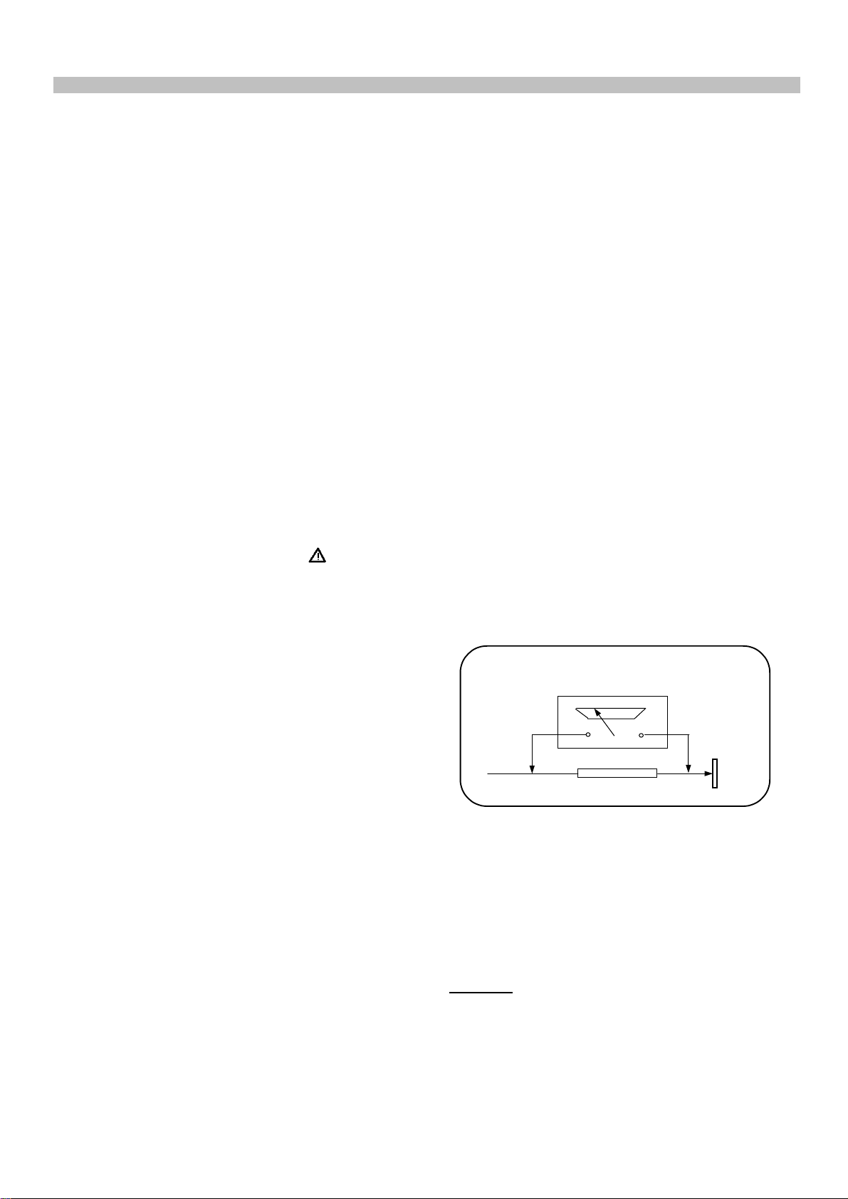
LEAKAGE CURRENT HOT CHECK
1. Plug the AC cord directly in to the AC
outlet. Do not use an isolation transformer
for this check.
2. Connect a 2Kohm 10W resistor in series with
an exposed metallic part on the receiver
and an earth, such as a water pipe.
3. Use an AC voltmeter with high impedance
to measure the potential across the resistor.
4. Check each exposed metallic part and
check the voltage at the each point.
5. Reverse the AC plug at the outlet and
repeat each of the above measurements.
6. The potential at the any point should not
exceed 1.4 Vrms. In case a measurement is
outside the limits specified, there is the
possibility of a shock hazard, and the
receiver should be repaired and rechecked
before it is returned to the customer.
replace the spacers with the originals.
Furthermore where a short circuit has
occurred, replace those components that
indicate evidence of overheating.
5. After servicing, see that all the protective
devices such as insulation barriers, insulation
HOT CHECK CIRCUIT
TO INSTRUMENTS
EXPOSED
METALLIC PARTS
AC-Voltmeter
Water pipe
(earth)
papers, shields and isolation R-C
combinations are correctly installed.
2 K Ohm
6. When the receiver is not being used for a
long time of period of time, unplug the
power cord from the AC outlet.
7. After servicing make the following leakage
current checks to prevent the customer
from being exposed to shock hazard.
LEAKAGE CURRENT COLD CHECK
1. Unplug the AC cord and connect a jumper
between the two prongs of the plug.
2. Turn the receiver’s power switch on.
3. Measure the resistance value with an
ohmmeter, between the jumpered AC plug
Figure 1
X-RAY RADIATION WARNING
The primary source of X-ray radiation in this receiver
is the picture tube. The chassis is specially
constructed to limit X-ray radiation. For continued Xray radiation protection, replace the tube with the
same type of the original one.
CAUTION
AFTER REMOVAL OF THE ANODE CAP, DISCHARGE
THE ANODE OF THE PICTURE TUBE AND THE ANODE
CAP TO THE METAL CHASSIS, CRT SHIELD, OR THE
CARBON PAINTED ON THE CRT WITH A HIGH
VOLTAGE PROBE AND MULTIMETER (SELECT VDC)
AND THEN SHORT CIRCUIT DIRECTLY TO DISCHARGE
COMPLETELY.
- 3 -
Page 4

Television
Thank you for buying this television which is designed to give you many years of
satisfactory service.
You may already be familiar with using a television but do please take time to read these
instructions. They are designed to familiarise you with the unit’s many new features
and to ensure you get the very best out of your purchase.
Special features
• Your TV can receive stereo channels directly (NICAM optional).
• Automatic tuning system with country selection.
• 100 Programme Memory
• Available for Cable Channels (A decoder maybe required)
• Manual Fine Tuning
2
• Child Lock
• Return to the last channel viewed (SWAP)
• Spatial Sound effect
• 16:9 picture format
• S-Video connection (optional)
• Audio/Video RCA sockets (optional).
• Back Audio Out (optional)
• Normalisation system to recall the setting in memory after the colour,contrast,
brightness setting have been changed.
• Picture adjustment using one button (Smart control).
• Sound adjustment using one button (Smart control).
• Equalizer Sound Setup
• Automatic Volume Limiting
• Your TV set is equipped with an On-Screen Display system. This system
enables the user to see the function on-screen and to control them efficiently.
• Infrared Remote Control
• Virtual Dolby Surround (optional)
• Multi language menu system
• On Timer
• Off Timer
• Stereo headphone socket (optional)
• 2 Scart Socket: Video cassette recorder, satellite receiver, video disc player,DVD, TV
games or a home computer can be connected to this AV socket with an appropriate
connecting cable.
• Third scart socket (optional).
• Subwoofer (optional)
• Zoom, Letterbox, Subtitle picture formats ( for Widescreen TV sets)
• Naming the channels
• Teletext reception
• Auto recognition of the broadcasting format (4:3, 16-9 or Letterbox) via WSS feature.
Page 5

Safety is Important
Your safety and the safety of others is important. Please, therefore, ensure you read
the Safety
instructions
before you operate this television.
Safety instructions
Read all the safety instructions before first use of your TV.
!
• Position the television so that direct light does not fall on
the screen. Excessive light will cause a washed out effect.
• Position the power supply lead and other leads so that
they are not likely to be walked on or pinched by things
placed on or against them.
• Do not use the appliance in humid or damp conditions.
Do not allow the appliance to get wet, i.e. dripping or
splashing, as this may be dangerous. Do not place water
filled objects, such as vases and flower top on top of the
appliance.
• Make sure that no naked flame sources, such as lighted
candles, are placed on top of the appliance.
• Do not place the television near heat sources such as
radiators, ovens, stoves, etc.
• Do not use the television near any apparatus that produces
a magnetic field such as HI-FI speakers or electric motors
otherwise colourpurity may be affected.
3
• The heat built up in the set escapes through ventilation
holes, so do not cover the set by drapes, clothes etc. that may
block air circulation. Do not place the television on carpet
or soft furnishings.
• NEVER let children push anything into the holes or slots
on the case.
• Clean the TV Screen using a slightly damp cloth or chamois
leather. Never use abrasive cleaning agents like liquid or
aerosol cleaners.
• Remove the mains plug from the socket outlet while cleaning.
• If you wish to place the television on a shelf or in a wall
unit always ensure there is a minimum air gap of 8 cm
around the top, sides and rear of the television, to assist
ventilation.
• Your TV set is designed to operate with mains voltages
230V AC; 50Hz. Do not connect your TV set to power sources
other than the mains supply.
Page 6
Getting started
Remove your Television carefully
from the box. You may wish to
store the packaging for future use.
In the box
Inside your this package you should have:
• Television
• Remote control
• User guide
• AAA batteries x 2
4
Read these instructions before use.
Aerial connection
To connect an aerial, plug the aerial lead
into the aerial socket on the rear of the
TV.
You can use an outdoor or indoor aerial.
However, if you use an indoor aerial the
quality of the reception may be reduced
and adjustment of the aerial may be
required when changing programs.
Please note
If you live in a poor reception area or use an
indoor aerial you may experience loss or
corruption of teletext transmissions.
Please Note
When not in use disconnect the plug
from the mains power supply.
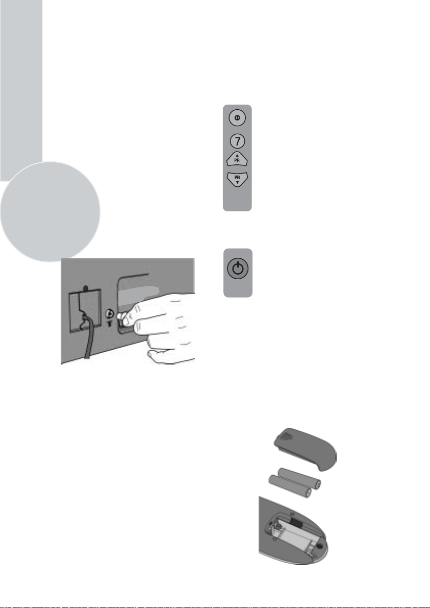
Press the Power button on
the front of the TV. The
standby indicator will
illuminate.
Press a Numeric button or the
Program up or Program down
button on the remote handset or
Program up or Program down
button on the front panel to
switch the TV on.
The standby indicator remains on.
The picture will appear after a
few seconds.
Press the Standby
the TV to standby. The standby
indicator will brighter.
Please Note
Do not leave the television on standby
unattended or overnight.
Switching the TV on for the first time
To install your TV, please read the sections
“TV controls” and “ Tuning the television”.
button to switch
Battery fitting
Insert the 2 AAA Batteries supplied into
the compartment on the rear of the remote
control, ensure you follow the polarity
diagram inside the compartment.
Switching on
Mains power
Connect the mains plug into the mains
socket and switch on.
Connect the TV mains plug into your domestic
mains socket outlet (230 V 50 Hz AC).
Page 7
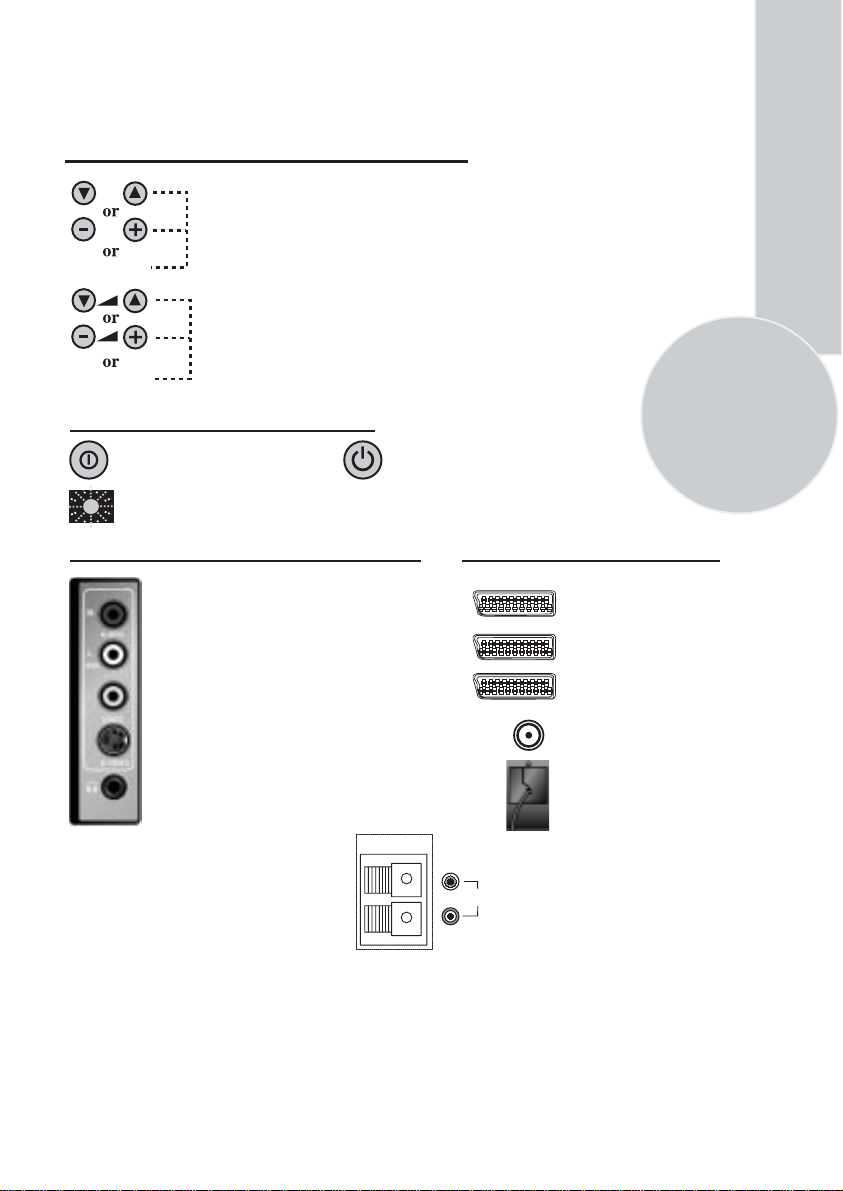
Control Unit
Front Panel
Program Down/Up button
P- P+
Volume Down/Up button.
V- V+
General
Program ON/OFF switch Stand by (Depends on model)
Stand by indicator
External Connections: (Front or side)
Right audio RCA (Red)
Left audio RCA/Mono RCA (White)
Video RCA (Yellow)
S-Video connection
Headphone socket
Optional
SUBWOOFER
It is used for external
subwoofer in 33” televisions
Please note
• See the external connections table on next page for available connections depending the
size and model of your TV set.
• Do not use Video RCA and S-Video connections at the same time, otherwise they will effect
the picture each other.
(External connections: (Rear)
AV1 scart
AV2 scart
AV3 scart (optional)
Aerial socket
Power cable
You may wish to connect
R
L
audio amplifier or any
similar devices to audio
AUDIO
OUT
out. The output is always
the current channel you
are watching.
5
Page 8
External connections table
Picture tube
size/typee
AV1 Scart
AV2 Scart
AV3 Scart
Headphone
socket
Audio/Video
RCA
6
S-Video
socket
Back Audio
Out
: Standart
STD
: Optional
OPT
: Not available
N/A
25”
4:3
STD. STD. STD. STD. STD.
STD.
OPT. OPT. OPT. OPT. OPT.
OPT. OPT. OPT. OPT. OPT.
OPT. OPT. OPT. OPT. OPT.
OPT. OPT. OPT. OPT. OPT.
OPT. OPT. OPT. OPT. OPT.
26”
16:9
STD.
STD.
OPT.
OPT.
OPT.
OPT.
OPT.
28”
4:3
STD. STD. STD. STD.
28”
16:9
29”
4:3
32”
16:9
33”
4:3
STD.
STD.
OPT.
OPT.
OPT.
OPT.
OPT.
Please note:
The Audio/Video RCA, S-Video and Headphone socket can be placed on the front panel
or on the right-hand side of the cabinet depending to the model of your TV.
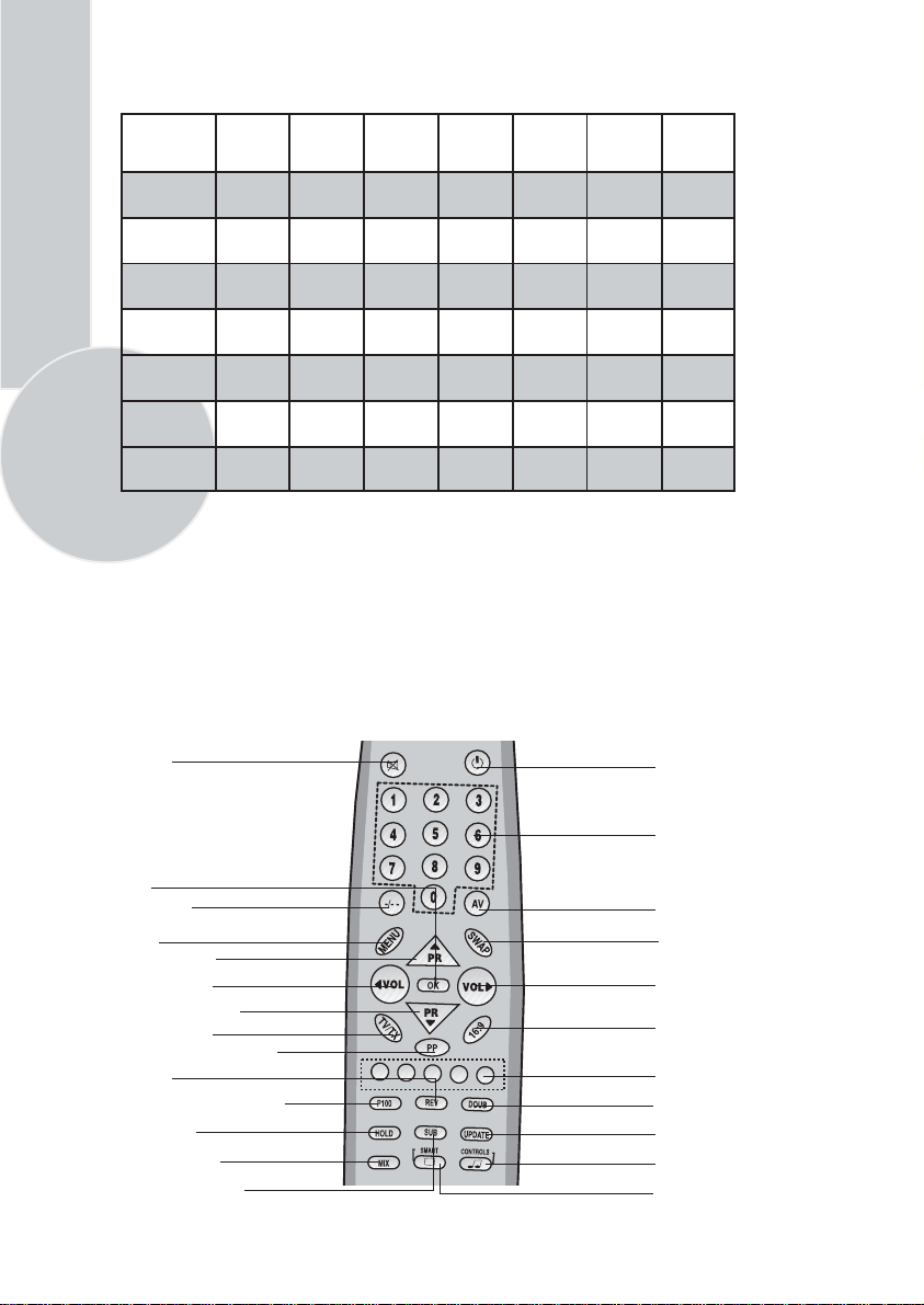
Remote control
Mute
Standby
OK
Two digit
Menu
Program up
Volume down
Program down
TV/Teletext
Personal preference
Reveal
Info/Index page (text)
Page hold
TV/Text mix
Sub page/Clock
Numeric
AV
Swap
Volume up
Picture format
Menu/Fast text
Double height text
Update
Sound smart control
Picture smart control
Page 9
Using the TV
TV controls
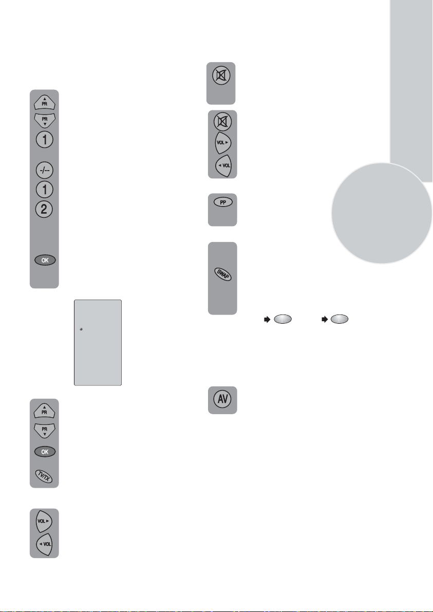
Programme selection
Press the Program up or Program
down buttons on the TV or remote
control or press a Numeric button
to select a programme.
To select a programme whose
number is greater than 9 using the
numeric buttons, press the -/--
button first and then press the two
Numeric buttons. For example, to
select programme 12, press the-/--
button followed by1 and then 2.
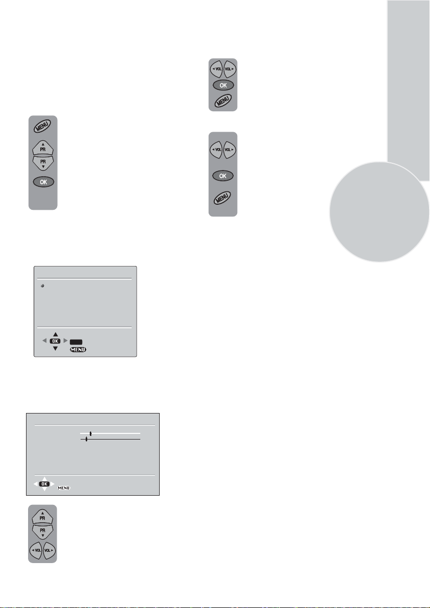
You can also select a program by
pressing in the OK button.
Press the OK button and a grey
box will appear on the screen
with programme numbers on it.
P00
P01
P02
P03 TRT1
P04 TRT2
P05 STAR
P06 CY 470
P07
P08
P09
P10
P11
P12
P13
P14
P15
Use the Program up and Program
down buttons to scroll through the
programme numbers. When you
find the program number you want
press theOK button again.
Press theTV/TX button to close
the grey box.
Volume
Press theVolume + or Volume -
button on the TV or the Vol or
▲
Vol button on the remote control.
A sound level bar will appear on the
screen.
▲
Mute
To mute the sound press the Mute
button on the remote control. A
loudspeaker symbol will appear on
the screen.
Press the Mute button again to
restore the sound. The symbol
will disappear.
Pressing Volume up buttons
to decrease headphone volume.
Pressing the Volume down button
increase tne headphone volume.
PP
Personal preference. Press the
PP
button to revert to the
default settings for the TV.
Swap
(See TV setup).
Allows you to swap between the
program you are watching and the
last selected program. i.e. If you were
watching Program 1 and change to
Program 11, press theSwap button
to go back to Program 1. Press it
again to return to Program 11.
PR 01
SWAP
PR 11
SWAP
PR 01
AV
For use when you are connecting an external
source to your TV (Video recorder, DVD
player etc.) via the SCART sockets or RCA
sockets.
See ‘Connecting external equipment’.
Press theAV button to select your
input as follows:
2 Scart models:
1 AV1 when using SCART socket 1.
2 AV2 when using SCART socket 2.
3 AV2S for S-Video equipment.
4 AV3 when using the RCA sockets
of the TV. (Optional)
5 AV3S when using the S-video socket and
RCA audio sockets of the TV. (Optional)
3 Scart models:
1 AV1 when using SCART socket 1.
2 AV2 when using SCART socket 2.
3 AV2S for S-Video equipment.
4 AV3 when using SCART socket 3.
5 AV4 when using the RCA sockets
of the TV. (Optional)
6 AV4S when using the S-video socket and
RCA audio sockets of the TV. (Optional)
7
Page 10
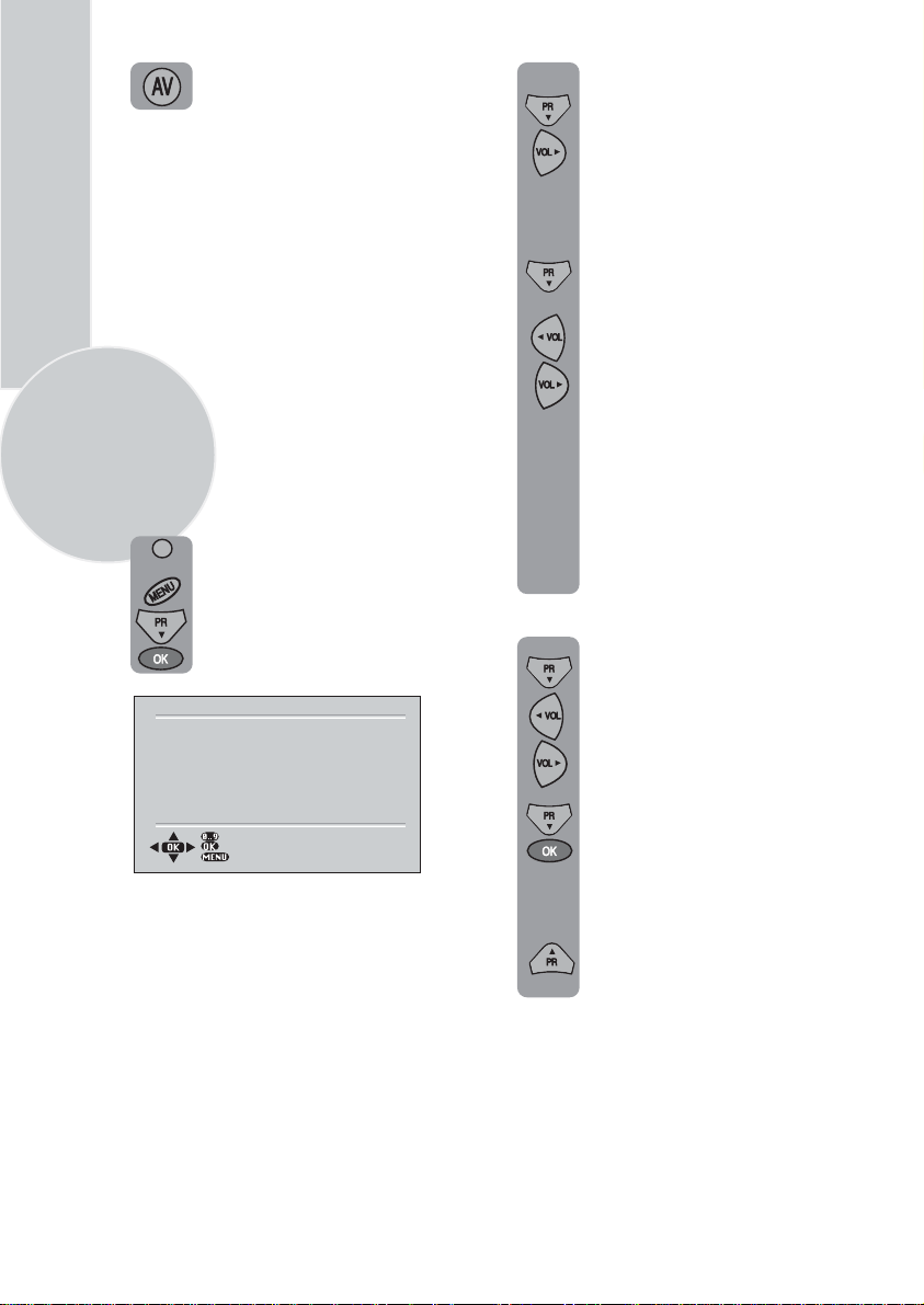
Press the AVbutton again to return
to TV.
In the Setup menu select PROG
NO and change to P1 using
the Program down button to
Tuning the television
There are two ways of tuning your television:
Manual, where you control the tuning process
or
Autoprogram where the television does it all
automatically.
Please Note
select it and the Volume up
button to change it.
Starting with Program 1, tune
in the first channel as follows:
Use the Program down button
to select SEARCH.
If the TV is set to a channel with no signal the
TV will return to standby after 5 minutes.
The time remaining is displayed on the screen
last 60 second.
8
Manual tuning
Tuning the TV is accessed through the
SETUP menu.
Press the Volume up or Volume
down button to start the tuning
search.
When the search finds a strong
channel signal it will stop
searching. The picture will appear.
There are two ways to access the SETUP
menu:
Press the blue Setup button.
or
Press the Menu button and use the
Program down button to select
SETUP. Press theOK button to
enter the SETUP menu.
C/S
BACK
SETUP
S 07
BG
0
< >
OFF
P1
CHANNEL
SYSTEM
FINE TUNE
SEARCH
AUTOPROGRAM
CHILD LOCK
PROGRAM NO
STORE
Please note
The system will displayed automatically on
SYSTEM row i.e.BG, L, I, DK depending
the receiving broadcasting system of the
country. In some countries the broadcasting
system can be both in BG/DK or BG/LL´.
Only the TV sets produced with Pal Secam
BG/DK or Pal Secam BG/LL´ systems can
receive both BG/DK or BG/LL´ broadcasts.
In this case the user can select the required
SYSTEM using Volume up/down buttons.
Identify which channel you are
watching (BBC 1, ITV 1 etc.) and
decide which program number you
want it to be.
Use the Program down
button to
select PROGRAM NO.
Use the
Volume up/down
buttons
to select the program number.
Use the Program down button to
select Store. Press theOKbutton
and STORED will appear on the
STORE line.
You have now stored the first
channel.
Use the Program up button to
select again SEARCH and
continue the tuning procedure
until you have tuned in all the
programmes you want or the
television can receive.
Please note
If you do not press any buttons for 15 seconds
the TV will exit the menu system.
Page 11
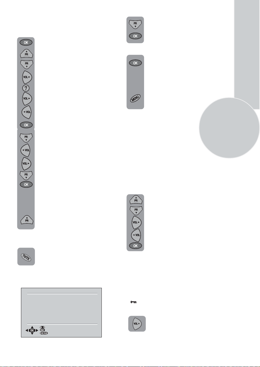
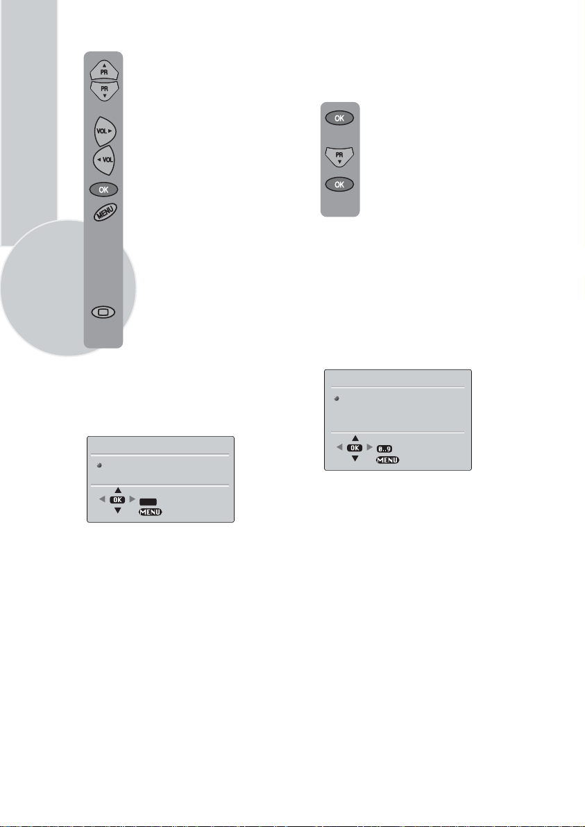
Tuning with channel numbers
Enter the SETUP menu by pressing
the blue button.
Press the OK button to enter the
CHANNEL row.
Use the OK button to select
“S” for cable channels and
“C” for terrestrial broadcast.
Use Volume up button to select
the channel number buttons.
Enter the channel number using
the Numeric buttons.
Use the Program down button to
select AUTOPROGRAM and
press
the OK button. A list of
countries will appear. Select
the desired country using
Program and Volume buttons.
When you are sure the aerial is
connected properly press the OK
button. Autoprogam will start.
To cancel Autoprogram whilst it
working press the Menu button.
is
Press the Program down/up
buttons to exit the channel row.
Use the Program down button to
select PROGRAM NO.
Use the Volume up/down buttons
to select the program number.
Use the Program down button to
select STORE. Press the
OKbutton
and STORED will appear on the
STORE line.
You have now stored the first
channel.
Use the Program up button to
select again SEARCH and continue
the tuning procedure until you
have tuned in all the programmes
you want or the television can
receive.
To exit the SETUP menu press the
TV/TX button.
Automatic tuning (Autoprogram)
Enter the SETUP menu as before.
C/S
BACK
SETUP
S 07
BG
0
< >
OFF
P1
CHANNEL
SYSTEM
FINE TUNE
SEARCH
AUTOPROGRAM
CHILD LOCK
PROGRAM NO
STORE
Your TV is now tuned and ready to use.
Please note:
If auto sort fails to arrange the programmes
in the required sequence please refer to
programme table.
Fine tuning
Although the search and Autoprogram
will automatically try and tune to the
best reception, in areas of poor reception
a bit of fine tuning may be required.
In the SETUP menu use the
Program up/down buttons to
select FINE TUNE. Use the
Volume up and Volume down
buttons to fine tune.
When you have finished use the
Program down button to select
STORE and press the OK button.
Child lock
Childlock switches off the programme you are
watching when you select it. All other
programmes are unaffected. If you go back to
the programme with childlock on you will see
a black screen with the OSD showing
“
”. You can lock as many programs
as you want.
Press the Volume up button to
switch the Child lock on or off.
9
Page 12
10
Program Table
Once you have tuned in all the channels you
want, you can change their programme
number, if required, and name them.
To enter the PROGRAM TABLE
menu press the Menu button and
select PROGRAM TABLE and
press
the
OK button or press
directly the Yellow button.
PROGRAM TABLE
P05
P06
P07
P08
P09
PROGRAM 01 will be selected and the
channel stored under PROGRAM 01 will be
showing on the screen.
The buttons used to edit the programs are
shown at the bottom of the display:
Blue button - Name
Green button - Move
Pink button - Delete
Red button - Skip
To name the programmes
OK
P10
P11
P12
P13
P14
SELECT
SKIP
MOVE
P15
P16
P17
P18
P19
BACK
NAME
DELETE
Press theBlue button, the selected
line will turn blue and the CH will
turn white.
Use the Program up and Program
down buttons to select the letters
and numbers and the Volume up
and Volume down buttons to
move through the name.
Press the Blue button again to store
the name.
Repeat this process to name all the
programmes.
Please Note
Some TV channels may send their
names with teletext transmission. In this
case their names will be automatically
shown on the name line.
To move the programmes
You can move the programmes around the
programme list to the order you want
Select the programme you want to
move and press the
Green button.
The programme will turn to green.
Select the number you want to move
the programme to and press the
Green button again and the
programme will be moved to that
number.
All the following programmes are
shifted down by one place.
To delete a programme
To delete a programme, select it and
press the Pink button. The
programme will turn pink and
the programme will be deleted.
All the following programmes are
shifted up by one position.
To skip programmes
Skipped programmes will not appear
when you move through the program
list using the Program up/
Program down buttons.
They can still be selected using the
numeric buttons or the OK button.
Select the programs you want to
skip
and press the Red button. The
program will turn red. To unskip the
program press the Red button again.
To exit the PROGRAM TABLE press
the TV/TX button once,Yellow button
or the Menu button twice.
When you select a programme, the
information you entered in the
PROGRAM TABLE menu will appear
on the top of the screen i.e. P1
BBC1.
This will disappear after
about three seconds.
Page 13
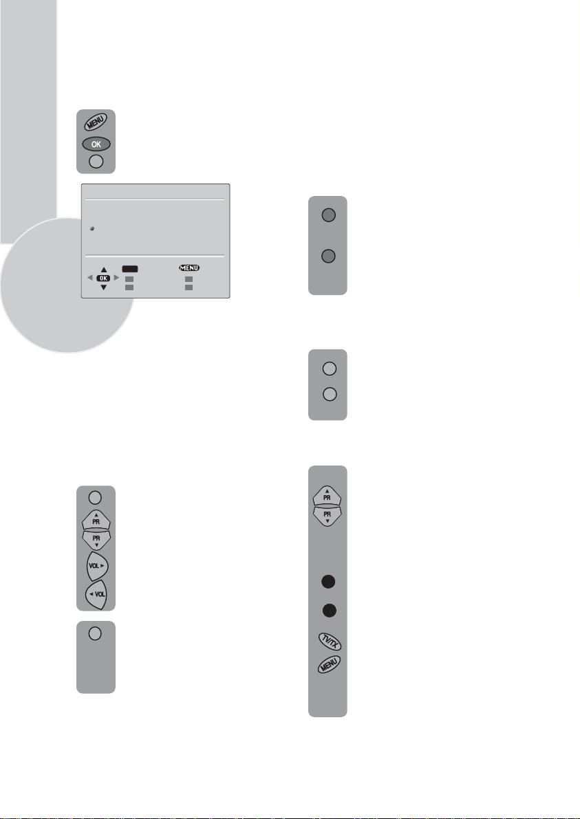
TV set up
The TV set up is accessed through a menu
system.
Once you have stored your set up, this is the
set up the TV will default to when you switch
it on.
To enter the MAIN menu press the
Menu button.
Once in the MAIN menu use the
Program up and Program down
buttons to select items in the menu
and the OK to access sub menus
or use the coloured fastext buttons
for quick access.
Red button
Green button
Yellow button
Blue button
Pink button
SOUND
PICTURE
PROGRAM TABLE
SETUP
FEATURES
Please note
If you do not press any buttons for 15 seconds
the TV will exit the menu system.
Sound menu (red button)
VOLUME
BALANCE
SOUND TYPE
SOUND MODE
AVL
DYNAMIC BASS
EQUALIZER
STORE
- SOUND
- PICTURE
- PROGRAM TABLE
- SETUP
- FEATURES
MAIN MENU
OK
SELECT
EXIT
SOUND
MONO
NORMAL
ON
ON
BACK
Volume
Sets default volume using the Volume up
and down buttons.
To save your settings, select
STORE
and press the OK button.
STORED
will be displayed. Press
the Menu button to go back to
the previous menu.
Balance
Sets the sound balance when the
is in stereo mode using the
TV
Volume up and down buttons
To save your settings, select
STORE
and press the OK button.
STORED
will be displayed. Press
the Menu button to go back to the
previous menu.
Sound type
This item shows STEREO when receiving
stereo
transmission and MONO for mono
transmissions.
The TV can be produced to receive the
NICAM broadcasts as a optional
feature.
If the channel you are watching
Nicam stereo the On
Screen Display
is in
will show NICAM STEREO for a
while.
Please Note
If, while watching a nicam stereo channel,
the signal strength drops and the system
cannot receive nicam stereo the OSD will
show MONO. If the signal strength
increases again and nicam stereo can be
received again, the OSD will show
NICAM STEREO.
11
Select the required item in the menu
using the Program up/down buttons
and make the changes pressing
Volume up/down buttons. Use the
OK button to enter EQUALIZER
sub menu.
Page 14
12
Sound mode
You can select NORMAL, SPATIAL or
DOLBY VIRTUAL (optional)using the
Volume up/down buttons or mix button.
SPATIAL sound is an ‘expanded stereo’. It
gives the impression that the two speakers in
the TV are further apart than they really are.
DOLBY VIRTUAL is based on Dolby Pro
Logic decoding for production of the Left,
Right, Centre and Virtual Surround Sound
channels using two loudspeaker.
® “DOLBY”, “VIRTUAL DOLBY
SURROUND” and the double- D
symbols are trademarks of Dolby
Laboratories Licensing Corporation.
Please Note
To get the surround effects in Virtual Dolby
mode, you must apply a Dolby Pro Logic
coded input to the TV.
You can’t adjust the AVL and EQUALIZER
in DOLBY VIRTUAL mode.
To save your settings, select STORE
and press theOK button. STORED
will be displayed. Press the Menu
button to go back to the previous
menu.
AVL
TV transmitters have different sound levels.
AVL (automatic volume limiting) maintains
the same sound level as you switch from
program to program.
To supply this press Volume up or down
button and select ON for AVL.
To save your settings, select STORE
and press theOK button. STORED
will be displayed. Press the Menu
button to go back to the previous
menu.
Dynamic Bass (optional)
Set DYNAMIC BASS to ON if you
wish to deepen the bass sound specifically.
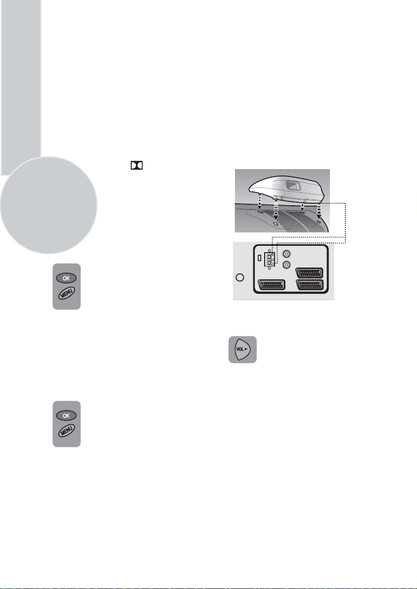
Subwoofer (optional)
A sub woofer speaker can be fitted
within the TV case as an option
depending to the model.
For 33”(84cm) TV sets there
is an external subwoofer (optional)
to be fixed as shown below.
R
AUDIO OUT
L
AV3
AV1
AV2
Select Sound menu and press
Program down button to access
subwoofer.
Press the Volume up button to
switch the Subwoofer on or off.
Please Note
If you move the loudspeaker switch, on the
rear of the TV, to the external position, the
internal speakers in the TV will be switched
off but the Subwoofer will remain on if
switched on.
Page 15
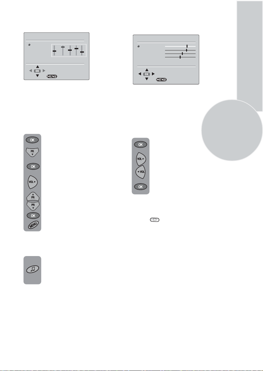
Equalizer
MUSIC
SPORTS
CINEMA
SPEECH
USER
EQUALIZER
0.1 0.5 1.5 5 10
Picture menu (Green button)
PICTURE
BRICGHTNESS
CONTRAST
COLOUR
SHARPNESS
COLOUR TEMPERATURE
STORE
BACK
In this menu are a series of preset equalizer
settings for different types of sound output.
There are five music settings - MUSIC,
SPORTS, CINEMA, SPEECH and USER
mode.
USER allows you to set your own sound
output as follows:
Plase the OK button to enter the
use EQUALIZER menu.
Use the Program down button to
select USER.
Press OK button to adjust the
frequency band levels.
Use the Volume up button to select
the KHz column you want to
change.
Use the Program up/down
buttons to make the changes.
To save your settings,
press the OK
button. Press the Menu button to
go back to the previous menu.
You can change the equalizer setting
whilst watching the TV using the
sound Smart control.
BACK
The picture menu allows you to set up the
following:
BRIGHTNESS
CONTRAST
COLOUR
SHARPNESS
COLOUR TEMPERATURE
To change, for example, the colour,
select it using Program buttons.
Use the Volume up and Volume
down buttons to change the setting.
To save your settings, select STORE
and press the OK button. STORED
will be displayed.
Smart cont.
This gives you a choice of picture type:
SOFT, NATURAL, RICH or USER.
Use the
button to change this type.
13
Press the sound Smart control to
page through the different equalizer
settings and select the one you
want.
Once you have switched the TV off
the equalizer setting will revert to the
stored setting.
Page 16
14
Select BRIGHTNESS,
CONTRAST, COLOUR and
SHARPNESS using the Program
up/down
buttons.
Change the settings with the
Volume up/down buttons.
To save your settings, select STORE
and press the OK
button. STORED
will be displayed. Press the Menu
button to go back to the previous
menu.
You can change the picture type
whilst watching the TV using the
picture Smart control.
Press the picture Smart control to
page through the different picture
types and select the one you want.
Once you have switched the TV off
the picture type will revert to the
stored setting.
Features Menu (Pink button)
Language
There are many languages available for the On
Screen Displays (OSD).
Press the OK button to select the
language list.
Press the Program down button to
page through all the languages and
OK to select.
Timer:
Use Program up and down
buttons to select Timer in the features
menu. Using the Timer fuction, you can
switch to a specific programme at a preprogrammed time or you can turn your TV
off at the time you want your TV to be
turned off.
Press OK to access the Timer menu.
TIMER
CLOCK
ON TIME
OFF TIME
PROGRAM No
--:--
--:--
--:-P1
LANGUAGE
TIMER
FEATURES
OK
SELECT
BACK
BACK
Clock:
Use the numeric buttons to set the
real time.
On Time:
Use the numeric buttons to set
the time that you want your TV to be turned
on (TV should be on stand-by mode).
Off Time:
Use the numeric buttons to set
the time that you want your TV to be turned
off (Stand-by mode).
Program No:
Use the numeric buttons to
set the programme number that will be
shown when you set the On Time.
Page 17
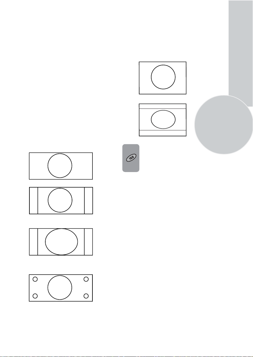
Picture format
This allows you to select the picture size on
corresponding to the scren type widescreen
of your TV:
Avaible formats for widesereen TV sets are
16:9, 4:3, zoom, Letterbox and Subtitle.
Avaible formats of 4:3 TV sets are 4:3 and
16:9.
The formats of the broadcasts (4:3 or 16:9)
you watch by means of aerial input are chosen
automatically. (4:3, 16:9 and Letterbox for
16:9 TV) This feature is active if the channel
you are watching sends WSS (Wide Screen
Signalling) information.
Note: The feature mentioned above is relevant
for TV sets having tele-text.
Widescreen TV sets:
16:9, this is the screen format of widescreen
TV sets (26” PF, 28” SF/PF, 32” SF/PF).
The TV will automatically switch to this
format if it detects 16:9 format from the
SCART inputs.
4:3, conventional TV picture format.
4:3 Sets:
4:3, is the screen format of 25”, 28”, 29”
and 33” TV sets But you can change
the picture format to 16:9 to able
to watch the inputs in 16:9 format, i.e.
some broadcasts and DVD’s.
15
Press the 16:9 button to page
through the different picture formats
and select the one you want. The
selected format will appear on the
lower center of the screen for
a short while.
Once you have switched the TV off
the picture format will revert to the
stored setting.
Zoom, an enlarged 4:3 format retaining the
same aspect ratio.
L Box (Letter box), Useful for watching
video, some film formats and Pal-Plus
format.
Page 18

Using Teletext
16
Teletext is an information system that displays
text on your TV screen. Using the teletext
control buttons you can view pages of
information that are listed in the teletext
index.
Please Note
No on screen display is available in text mode.
The contrast, brightness and colour cannot be
changed but the volume control is still
available.
To enter Text mode
Please Note
Make sure the TV channel you are watching
transmits teletext.
Press the button. The text
page will appear, normally the index
page.
To exit Text mode
Press the button. The TV
will return to the channel you were
watching.
To select a page of text
Find the number of the page in the
index and enter it using the
Numeric
the page will appear in the top left
hand corner of the screen.
The page counter will search for your
page. When it finds it, the page will
be displayed.
To move to the next page of text
press the button.
To move to the previous page press
the button.
TV/TX
TV/TX
buttons. The number of
Program up
Program down
TV/text mix
To view a page of text whilst
watching a TV programme press
the
Mix
button. The text will be
superimposed over the TV
programme.
Press the
to the text page.
Page search whilst watching TV
In Text mode press theUpdate
button. The TV will return to TV
mode with the text page number in
the top left hand corner of the
screen.
Enter the page number you want
using the buttons.
The top line of the text page will
appear whilst the text searches for
your page. When the page is found
the number will remain in the top
left hand corner of the screen.
Press the button to view
your selected page of text.
Double height text
If you have difficulty reading the
text on the TV you can double the
height of the text.
Press the button.
The top half of the page will be
displayed in double height text.
Press the button again.
The bottom half of the page
will be displayed in double height
text.
button again to return
Mix
Numeric
Update
Doub
Doub
To return to the index page press the
button.
P100
Press the button
again to return to the full page.
Doub
Page 19

Page hold
If the page of text you have selected
contains sub pages, these sub pages
will automatically be displayed in
order with a delay to allow you to
read the page.
To stop the move to the next sub
page press the Hold button. STOP
will appear in the top left hand
corner.
To continue moving through the sub
pages press the Hold button again.
To select a sub page
If the page of text you are viewing
contains sub pages, the number of
the sub page you are on and the total
number of sub pages is displayed on
the right of the screen i.e. 1/7.
To select a sub page press the Sub
button. The number in the top left
hand corner will be replaced by S
followed by 4 asterisks.
Enter the number of the sub page,
using the Numeric buttons in the
format S0001 for sub page 1.
The teletext will search for the sub
page. This may take some time. To
return to the TV whilst the teletext
is searching press the Update
button.
When the page number is found it
will appear in the top left hand
corner of the screen.
To reveal information
Press the Rev button to reveal
concealed information (quiz
answers etc.).
Press the Rev button again to
conceal the information again.
Clock
Press the Sub button, whilst
watching a TV program , to
SUB
display the time.
Fastext
At the bottom of the teletext screen is a row
of subject headings in red, green yellow and
blue.
The remote control has a row of coloured
buttons corresponding to the row of
coloured subjects on the screen.
Pressing one of the coloured buttons will
take you directly to the page
corresponding to the subject heading.
Toptext (optional)
At the bottom of the teletext screen is a row
of subject headings in yellow and blue.
Pressing yellow or blue buttons on the
remote control, selects the related Subject.
Next page can be selected by pressing the red
button and previous page can be selected
by pressing the green button.
Note: Fastext and Toptext features are not
available in every program.
17
Press the Update button again to
view the text page.
Page 20

Connecting external
equipment
18
Headphones (optional)
The headphones must have an impedance of
between 8 and 32 ohms and have a 3.5 mm
stereo jack plug.
Plug the headphone jack into the headphone
socket of the TV.
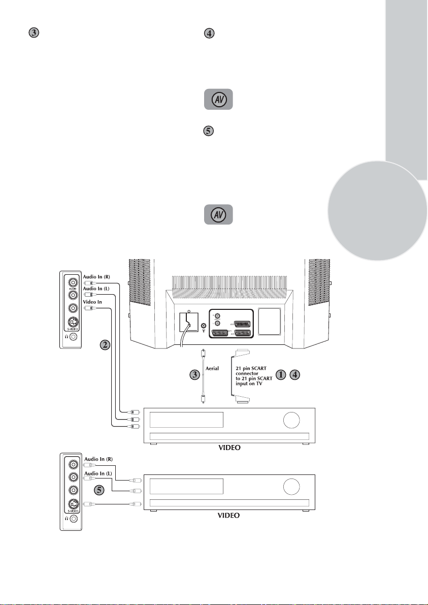
Connecting a video
recorder
Via SCART
Make sure the TV and video recorder are
both switched off.
Plug one end of the SCART lead (not
supplied) into the back of the video recorder
and the other end into one of the SCART
sockets on the back of the TV.
Switch on the video recorder and the TV.
Press the AV button on the remote
control to select AV1, AV2 or AV3
(optional) to
SCART socket you
back of the TV.
correspond with
are using on the
Please note:
You can connect a RGB external equipment
via Scart 1. It is necessary to you use full
Scart cable for this purpose.
Select the video outputs of external device
by using its menu to RGB if it’s available.
Via RCA lead (optional)
Make sure the TV and video recorder are
both switched off.
Plug one end of the RCA lead into the video
and audio out sockets on the back of the
video recorder and plug the other end into
the video and audio in sockets of the TV.
If the sound is in mono use the Audio Input
L. In the SOUND menu select MONO.
Press the AV button repetitively
and select the AV3 mode by two
scart models or select AV4 mode
by three scart models.
Page 21
Via aerial socket
Make sure the TV and video recorder are
both switched off.
Unplug the aerial lead from the TV and plug
it into the aerial socket on the video
recorder (if fitted).
Plug a coaxial plug into the RF out socket on
the rear of the video recorder and plug the
other end into the aerial socket of the TV.
Switch on the video recorder and the TV.
If your video recorder has a test signal, switch
it on. (Refer to the video recorder user guide).
See ‘Tuning the TV’ and carry out the tuning
procedure for the video recorder test signal.
Select a programme number 0 or between 55
and 99.
R
L
MONO
VIDEO
S-Video Player
If you have an S-Video player you can
connect it to SCART socket 2
via an adaptor from scart to S-Video/RCA
audio (not supplied).
Press the AV button three times
to select AV2S (available by two
scart models).
Via RCA lead and S-Video socket
You can also connect it through the
S-Video socket of the TV (optional).
Plug the S-Video plug into the S-Video
socket and the audio leads into the audio
sockets.
Press the AV button repetitively
to select AV3S by two scart
models or AV4S by three scart
models.
R
AUDIO OUT
L
AV3
AV1
AV2
19
R
L
MONO
VIDEO
S-Video In
Page 22

Connecting a DVD
player
Via SCART
Make sure the TV and DVD player are both
switched off.
Plug one end of the SCART lead (not
supplied) into the back of the DVD player
and the other end into one of the SCART
sockets on the back of the TV.
Switch on the DVD and the TV.
Via RCA lead (optional)
Make sure the TV and DVD player are both
switched off.
Plug one end of the RCA lead into the video
and audio out sockets on the back of the
DVD player and plug the other end into the
video and audio in sockets of the TV.
Press the AV button repetitively and
select the AV3 mode by two scart
models or select AV4 mode by three
scart models.
20
Press theAV button on the remote
control to select AV1, AV2 or AV3
(optional) to correspond with
SCART socket you are using
on the back of the TV.
R
L
MONO
VIDEO
Via RCA lead and S-Video socket
You can also connect it through the
S-Video socket of the TV (optional).
Plug the S-Video plug into the S-Video
socket and the audio leads into the audio
sockets.
Press the AV button repetitively
to select AV3S by two scart
models or AV4S by three scart
models.
R
AUDIO OUT
L
AV3
AV1
AV2
R
L
MONO
VIDEO
S-Video In
Page 23
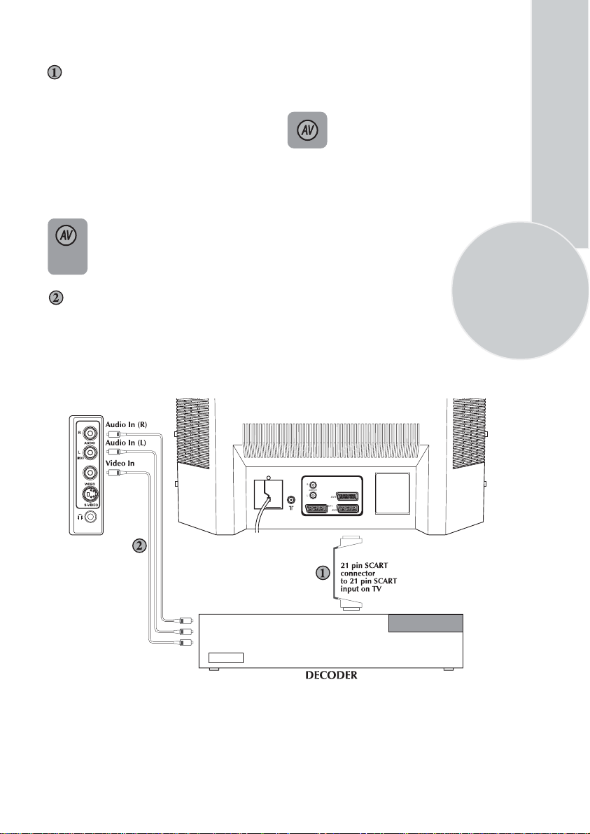
Connecting a decoder
Via SCART
Make sure the TV and decoder are both
switched off.
Plug one end of the SCART lead (not
supplied) into the back of the decoder and the
other end into the SCART1 on
the back of the TV.
Switch on the decoder and the TV.
Press the AV button on the remote
control to select AV1.
Via RCA lead (optional)
Make sure the TV and decoder are both
switched off.
Plug one end of the RCA lead into the video
and audio out sockets on the back of the
decoder and plug the other end into the video
and audio in sockets on
the TV.
Press the AV button repetitively and
select the AV3 mode by two scart
models or select AV4 mode by three
scart models.
Please Note
You can record from one external piece of
equipment to another via the TV by
connecting the playback to SCART 1 and the
recorder to SCART 2 or SCART 3 and
selecting AV1. You cannot watch the TV.
You can connect NTSC supported equipment
to the TV via the SCART sockets and
adjusting the colour via the PICTURE
menu.
Select TINT by using Program down
button and use the adjust the colour to
Volume up and down buttons.
21
R
AUDIO OUT
L
AV3
AV1
AV2
Page 24
22
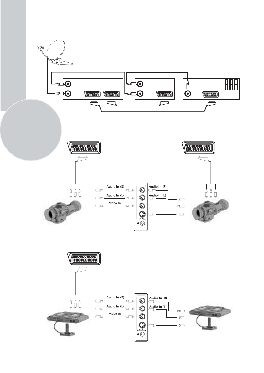
Connecting TV with video and satellite/digital
receiver
Satellite/digital receiver Video Rear of TV
Aerial out
Aerial in
TV
Scart socket
Video
Scart socket
Aerial out
Aerial in
Scart socket
Aerial
socket
Scart 1
Connecting TV with camcorder
AV1/AV2/AV3
R
L
VIDEO
Camcorder
AV3
(3 scart models only)
S-Video In
Connecting TV games and computer
AV1
R
L
VIDEO
S-Video In
S-Video camcorder
S-Video TV Game Player
Page 25

Help and service tips
The TV does not work
Make sure it is plugged into the mains supply
and switched on.
Poor picture
• Is the aerial plugged in?
• If you are using a set top aerial is it
properly aligned for the best signal.
• Make sure the aerial is not to close to
neon lights, loudspeakers etc.
• Try changing the direction of the outdoor
aerial. High buildings and mountains can
cause ghost pictures or double images.
• The picture quality may be reduced by
connecting two external sources at once.
Disconnect one of the sources.
• Adjust the fine tuning.
No picture
• Is the aerial plugged in properly?
• Is the aerial lead damaged?
• Are all the plugs in the aerial lead fitted
correctly?
• Have you pressed the correct buttons on
the remote control?
No sound
• Is the sound muted? Press the Mute
button.
• Is the volume turned down?
• Are there headphones connected?
Sound coming from only one
speaker
• Is the balance set to one side? See the
sound menu.
• If you have external speakers, has one of
them become disconnected.
No response to the remote control
• Try changing the batteries.
• Is there an obstruction between the
remote control and the sensor on the TV.
If nothing works
If you have tried the above solutions and none
seem to work, try switching the unit off and
on again.
If this does not work contact your supplier or
TV repair technician. Never attempt to
repair a defective TV yourself.
23
Page 26

Technical specifications table
24
Picture tube
size/type
Screen size
Visible
screen size
Sound Output
(%10 THD)
Power
consumption
Stand by
Power
consumption
Subwoofer
Dolby
Virtual
SF
PF
16:9
4:3
25”
4:3
63 cm 70 cm 70 cm 70 cm 70 cm 72 cm 82 cm 82 cm 84 cm
59 cm 66 cm 66 cm 66 cm 68 cm 68 cm 77 cm 77 cm 80 cm
2x10 W 2x10 W 2x10 W 2x10 W 2x10 W 2x10 W 2x10 W 2x10 W 2x10 W
3 W 3 W 3 W 3 W 3 W 3 W 3 W 3 W 3 W
optional optional optional optional optional optional optional optional optional
: Superflat picture tube
: Pureflat picture tube
: Widescreen TV
: Conventional TV
26”
28”
16:9 PF
68 cm
65 cm
2x10 W
90 W
3 W
optional
optional
28”
4:3
16:9 SF
90 W
optional—optional optional optional optional optional optional optional
28”
16:9 PF
29”
4:3 SF
95 W
29”
4:3 PF
95 W
32”
16:9 SF
95 W
32”
16:9 PF
95 W
33”
4:3
Please note:
Using a subwoofer causes 20 W extra power consumption and supplies maximum 20 W
extra sound output.
General technical specifications
Power Supply
AC: ................................................... 230-240V 50Hz
Number of preset programmes ......... 100
RF Aerial input .................................... 75
Speaker empedance ...........................
Audio output ...................................... Mono/Stereo/NICAM (optional)
Batteries ............................................ 2x AAA
Receiving channels ............................... VHF (Band I Channels 2-4)
............................................................. VHF (Band III Channels 5-12)
............................................................... UHF (Channels 21-69)
.............................................................. Cable TV (S1-S20/S21-S41)
ohm (unbalanced)
8 ohm
Please note: Your TV set is produced to receive only “one “ of this colour and sound system
options which is based one your countries norms and can not be changed by user except
BG/DK and BG/LL´ if both systems are avaible to receive (BG or DK and BG or LL´). Please
refer to “Tuning the TV”.
Page 27

VCT 49xxI ADVANCE INFORMATION
Volume 1: General Description
General Description
1. Introduction
The VCT 49xxI is an IC family of high-quality singlechip TV processors. Modular design and deep-submicron technology allow the economic integration of features in all classes of single-scan TV sets. The
VCT 49xxI family is based on functional blocks contained and approved in existing products like
DRX 396xA, MSP 34x5G, VSP 94x7B, DDP 3315C,
and SDA 55xx.
Each member of the family contains the entire IF,
audio, video, display, and deflection processing for 4:3
and 16:9 50/60-Hz mono and stereo TV sets. The integrated microcontroller is supported by a powerful OSD
generator with integrated Teletext & CC acquisition
including on-chip page memory.
Video & Sound IF
DRX 396xA
Audio Processing
MSP 34x5G
1.1. Features
The VCT 49xxI family offers a rich feature set, covering the whole range of state-of-the-art 50/60-Hz TV
applications.
– PSSDIP88-1/-2 package
– PMQFP144-2 package
– SubmicronCMOS technology
– Low-power standby mode
– Single 2 0.25-MHz reference crystal
– 8-bit 8051 instruction set compatible CPU
– Up to 256 kB on-chip program ROM
– WST,PDC,VPS,andWSSacquisition
– ClosedCaptionandV-chipacquisition
– Up to 10 pages on-chip teletext memory
– Multi-standard QSS IF processing with single SAW
– FM Radio and RDS with standard TV tuner
– TV-sound demodulation:
• all A2 standards
• all NICAM standards
• BTSC/SAP with MNR (DBX optional)
•EIA-J
Video Processing
VSP 94x7B
Display & Deflection
DDP 3315C
Control, OSD, Text
SDA 55xx
Fig. 1–1: Single-chip VCT 49xxI
VCT 49xyI
– Baseband sound processing for loudspeaker chan-
nel:
• volume
• bass and treble
• loudness
• balance
• spatial effect (e.g. pseudo stereo)
• Micronas AROUND (virtual Dolby optional)
• Micronas BASS
– CVBS, S-VHS, YC
and RGB inputs
rCb
– 4H adaptive comb filter (PAL/NTSC)
– multi-standard color decoder (PAL/NTSC/SECAM)
– Nonlinear horizontal scaling “panorama vision”
– Luma and chroma transient improvement (LTI, CTI)
– Non-linear color space enhancement (NCE)
– Dynamic black level expander (BLE)
– Scan velocity modulationoutput
– Soft start/stop of H-drive
– Vertical angle and bow correction
– Average and peak beam current limiter
– Nonlinear and dynamic EHT compensation
– Black switch off procedure (BSO)
1-4 Dec. 6, 2002; 6251-573-1-1AI Micronas
Page 28

VCT 49xxI ADVANCE INFORMATION
Volume 1: General Description
1.2. Chip Architecture
R
E
K
C
G
F
I
A
T
S
T
A
U
E
N
O
I
P
A
S
A
IFIN+
IFIN-
CVBS in
YCrCb in
RGB in
CVBS out
IF
Frontend
Video
Frontend
Slicer
24kB
Char ROM
20kB XRAM
IF
Processor
Comb
Filter
Component
Bus
Arbiter
256kB
Prog ROM
Interface
Sound
Demodulator
Color
Decoder
Display
Generator
Memory
Interface
CPU
8051
Panorama
Scaler
Audio
Processor
Display &
Deflection
Processor
I2C Master/
Slave
Timer
CRT
PWM
ADC
UART
Watchdog
RTC
I/O-Ports
Video
Backend
Reset & Test
Logic
Clock
Generator
PROT
HOUT
HFLB
VERT
EW
SVM
RGB out
RGB in
SENSE
RSW
I2C
RESETQ
TEST
XTAL1
XTAL2
Fig. 1–2: Block diagram of the VCT 49xxI
ADB, DB, PSENQ,
PSWEQ, WRQ, RDQ
Pxy
1-6 Dec. 6, 2002; 6251-573-1-1AI Micronas
Page 29

ADVANCE INFORMATION VCT 49xxI
Volume 1: General Description
1.3. System Application
20.25MHz
AOUT1
AV1
AIN1
RGB/FB/C1
VOUT1
CVBS1/Y1
ID1
IFIN+
SAW
IFIN-
TAGC
I2C
Tuner
AOUT2
AIN2
C2
VOUT2
CVBS2/Y2
AV2
ID2
C3
CVBS3/Y3
AIN3
AV3
Video L - Audio - RS-Video
Fig. 1–3: Stereo TV set with VCT 49xxI
separate
AIN3 only
available in
QFP package
H/V/EW
4:3/16:9 CRT
RGB/SVM
VCT 49xxI
SENSE
Lo udsp eaker
SPEAKER
Headphone
Micronas Dec. 6, 2002; 6251-573-1-1AI 1-7
Page 30

VCT 49xxI ADVANCE INFORMATION
Volume 1: General Description
20.25MHz
VOUT2
VOUT1
AOUT1
IFIN+
SAW
IFIN-
Tuner
Mon
AV1
AV2
AV3
Video L - Audio - RS-Video
DVD
Cb CrY
YCrCb
C1
CVBS1/Y1
AIN1
TAGC
I2C
4:3/16:9 CRT
H/V/EW
RGB/SVM
VCT 49xxI
SENSE
Video L - Audio - RS-Video
Video L - Audio - RS-Video
Video L - Audio - RS-Video
C2
CVBS2/Y2
AIN2
C3
CVBS3/Y3
AIN3
separate
AIN3 only
available in
QFP package
Lo udsp eaker
SPEAKER
Headphone
AOUT2
Fig. 1–4: Stereo TV set with VCT 49xxI
Page 31

ADVANCE INFORMATION VCT 49xxI
Volume 1: General Description
3. Control Interface
Table 3–1: I2C Slave Device Addresses
Block Device Address
Write Read
DRX h’8E h’8F
MSP h’8C h’8D
VSP h’B0 h’B1
DDP h’BC h’BD
TVT programmable
Computer
VCTI
IO-
Port
TVT
8051
I2C M/S
Interface
Buffer
DRX
int. I2C-Bus
ext. I2C-Bus
MSP
VSP
DDP
Fig. 3–1:
Tuner
I2C Environment
NVM
MSP
DPL
PIP
Page 32

VCT 49xxI ADVANCE INFORMATION
Volume 1: General Description
4. Specifications
4.1. Outline Dimensions
SPGS703000-3(P88)/1E
4488
±0.1
18
1 43
±0.1
57.7
0.87
±0.05
±0.2
±0.1
0.8
3.8
19.5
±0.15
1.27
±0.05
X
43 x 1.27 = 54.61
X 10:1
30 ˚C
±0.1
±0.1
3.35
0.28
±0.06
22.5
22.5
19.5
±0.15
±0.15
±0.15
2.77
Ø 1.5
2.02
Ø 0.75
1.27
±0.05
1.27
1.5
0.23
1.75
0.48
0.2
±0.06
1.97
Fig. 4–1:
88-Pin Plastic Staggered Shrink Dual Inline Package
(PSSDIP88-1/-2)
Weight approximately 9.6 g
Dimensions in mm
1-12 Dec. 6, 2002; 6251-573-1-1AI Micronas
Page 33

VCT 49xxI ADVANCE INFORMATION
Volume 1: General Description
PinConnectionsandShortDescriptions
NC = not connected
LV = if not used, leave vacant
OBL = obligatory; connect as described in circuit diagram
IN = Input Pin
OUT = Output Pin
SUPPLY = Supply Pin
Pin No. Pin Name Type Connection Short Description
PSSDIP
88-pin
1 128 GND SUPPLY OBL Ground Platform
2 129 VSUP5.0BE SUPPLY OBL Supply Voltage Analog Video Back-end, 5.0 V
3 130 TEST IN GND Test Input, reserved for Test
4 131 VERT+ OUT LV Differential Vertical Sawtooth Output
PMQFP-2
144-pin
(If not used)
5 132 VERT- OUT LV Differential Vertical Sawtooth Output
6 133 EW OUT LV Vertical Parabola Output
7 134 RSW2 OUT LV Range Switch 2 Output
8 135 RSW1 OUT LV Range Switch 1 Output
9 136 SENSE IN GND Sense ADC Input
10 137 GNDM IN GND Reference Ground for Sense ADC
11 138 FBIN IN GND FastBlank Input, Back-end
12 139 RIN IN GND Analog Red Input, Back-end
13 140 GIN IN GND Analog Green Input, Back-end
14 141 BIN IN GND Analog Blue Input, Back-end
15 142 SVMOUT OUT VSUP5.0BE Scan Velocity Modulation Output
16 143 ROUT OUT VSUP5.0BE Analog Red Output
17 144 GOUT OUT VSUP5.0BE Analog Green Output
18 1 BOUT OUT VSUP5.0BE Analog Blue Output
19 2 VRD OBL Reference Voltage for RGB DACs
20 3 XREF OBL Reference Current for RGB DACs
21 4 VSUP3.3BE SUPPLY OBL Supply Voltage Analog Video Back-end, 3.3 V
22 5 GND SUPPLY OBL Ground Platform
23 6 GND SUPPLY OBL Ground Platform
24 7 VSUP3.3IO SUPPLY OBL Supply Voltage I/O Ports, 3.3 V
25 8 VSUP3.3DAC SUPPLY OBL Supply Voltage Video DACs, 3.3 V
26 9 GNDDAC SUPPLY OBL Ground Video DACs
27 10 SAFETY IN GND Safety Input
1-14 Dec. 6, 2002; 6251-573-1-1AI Micronas
Page 34

ADVANCE INFORMATION VCT 49xxI
Volume 1: General Description
Pin No. Pin Name Type Connection Short Description
PSSDIP
88-pin
28 11 HFLB IN HOUT Horizontal Flyback Input
29 12 HOUT OUT LV Horizontal Drive Output
30 13 VPROT IN GND Vertical Protection Input
PMQFP-2
144-pin
(If not used)
37 PWMV OUT LV PWM Vertical Output
38 DFVBL OUT LV Dynamic Focus Vertical Blanking Output
31 39 SDA IN/OUT OBL I
32 40 SCL IN/OUT OBL I
2
C Bus Data Input/Output
2
C Bus Clock Input/Output
33 41 P21 IN/OUT LV Port 2, Bit 1 Input/Output
34 42 P20 IN/OUT LV Port 2, Bit 0 Input/Output
35 43 P17 IN/OUT LV Port 1, Bit 7 Input/Output
36 44 P16 IN/OUT LV Port 1, Bit 6 Input/Output
37 45 P15 IN/OUT LV Port 1, Bit 5 Input/Output
38 46 P14 IN/OUT LV Port 1, Bit 4 Input/Output
39 47 P13 IN/OUT LV Port 1, Bit 3 Input/Output
40 48 P12 IN/OUT LV Port 1, Bit 2 Input/Output
41 49 P11 IN/OUT LV Port 1, Bit 1 Input/Output
42 50 P10 IN/OUT LV Port 1, Bit 0 Input/Output
43 53 VSUP3.3FE SUPPLY OBL Supply Voltage Analog Video Front-end, 3.3 V
44 54 GND SUPPLY OBL Ground Platform
45 55 GND SUPPLY OBL Ground Platform
46 56 VSUP1.8FE SUPPLY OBL Supply Voltage Analog Video Front-end, 1.8 V
47 57 VOUT3 OUT LV Analog Video 3 Output
48 58 VOUT2 OUT LV Analog Video 2 Output
49 59 VOUT1 OUT LV Analog Video 1 Output
50 60 VIN1 IN GND Analog Video 1 Input
51 61 VIN2 IN GND Analog Video 2 Input
52 62 VIN3 IN GND Analog Video 3 Input
53 63 VIN4 IN GND Analog Video 4 Input
54 64 VIN5 IN GND Analog Video 5 Input
55 65 VIN6 IN GND Analog Video 6 Input
56 66 VIN7 IN GND Analog Video 7 Input
57 67 VIN8 IN GND Analog Video 8 Input
58 68 VIN9 IN GND Analog Video 9 Input
Micronas Dec. 6, 2002; 6251-573-1-1AI 1-15
Page 35

VCT 49xxI ADVANCE INFORMATION
Volume 1: General Description
Pin No. Pin Name Type Connection Short Description
PSSDIP
88-pin
59 69 VIN10 IN GND Analog Video 10 Input
60 70 VIN11 IN GND Analog Video 11 Input
61 98 P23 IN/OUT LV Port 2, Bit 3 Input/Output
62 99 P22 IN/OUT LV Port 2, Bit 2 Input/Output
63 100 XTAL2 OUT OBL Analog Crystal Output
64 101 XTAL1 IN OBL Analog Crystal Input
65 102 VSUP1.8DIG SUPPLY OBL Supply Voltage Digital Core, 1.8 V
66 103 GND SUPPLY OBL Ground Platform
67 104 GND SUPPLY OBL Ground Platform
PMQFP-2
144-pin
(If not used)
(main and standby supply)
68 105 VSUP3.3DIG SUPPLY OBL Supply Voltage Digital Core, 3.3 V
(main and standby supply)
69 106 VSUP5.0IF SUPPLY OBL Supply Voltage Analog IF Front-end, 5.0 V
70 107 GNDIF SUPPLY OBL Ground Analog IF Front-end
71 108 RESETQ IN/OUT OBL Reset
72 109 IFIN+ IN VREF
73 110 IFIN- IN VREF
IF
IF
Input/Output
Differential IF Input
Differential IF Input
74 111 VREFIF OBL Reference Voltage, IF ADC
75 112 TAGC OUT LV Tuner AGC Output
76 113 AIN1R /
SIF
IN/OUT GND Analog Audio 1 Input, Right
Analog 2nd Sound IF Output
77 114 AIN1L IN GND Analog Audio 1 Input, Left
78 115 AIN2R IN GND Analog Audio 2 Input, Right
79 116 AIN2L IN GND Analog Audio 2 Input, Left
117 AIN3R IN GND Analog Audio 3 Input, Right
118 AIN3L IN GND Analog Audio 3 Input, Left
119 AOUT2R OUT LV Analog Audio 2 Output, Right
120 AOUT2L OUT LV Analog Audio 2 Output, Left
80
81
AIN3R /
AOUT2R
AIN3L /
AOUT2L
IN /
OUT
IN /
OUT
LV Analog Audio 3 Input, Right
Analog Audio 2 Output, Right
LV Analog Audio 3 Input, Left
Analog Audio 2 Output, Left
82 121 AOUT1R OUT LV Analog Audio 1 Output, Right
83 122 AOUT1L OUT LV Analog Audio 1 Output, Left
84 123 SPEAKERR OUT LV Analog Loudspeaker Output, Right
1-16 Dec. 6, 2002; 6251-573-1-1AI Micronas
Page 36

ADVANCE INFORMATION VCT 49xxI
Volume 1: General Description
Pin No. Pin Name Type Connection Short Description
PSSDIP
88-pin
85 124 SPEAKERL OUT LV Analog Loudspeaker Output, Left
86 125 VREFAU OBL Reference Voltage, Audio
87 126 VSUP8.0AU SUPPLY OBL Supply Voltage Analog Audio, 8.0 V
88 127 GND SUPPLY OBL Ground Platform
PMQFP-2
144-pin
(If not used)
71 P37 /
656IO7
72 P36 /
656IO6
73 P35 /
656IO5
74 P34 /
656IO4
75 P33 /
656IO3
IN/OUT LV Port 3, Bit 7 Input/Output
Digital 656 Bus 7 Input/Output
IN/OUT LV Port 3, Bit 6 Input/Output
Digital 656 Bus 6 Input/Output
IN/OUT LV Port 3, Bit 5 Input/Output
Digital 656 Bus 5 Input/Output
IN/OUT LV Port 3, Bit 4 Input/Output
Digital 656 Bus 4 Input/Output
IN/OUT LV Port 3, Bit 3 Input/Output
Digital 656 Bus 3 Input/Output
76 GNDEIO SUPPLY OBL Ground Extended I/O Ports
77 VSUP3.3EIO SUPPLY OBL Supply Voltage Extended I/O Ports, 3.3 V
78 P32 /
656IO2
79 P31 /
656IO1
80 P30 /
656IO0
IN/OUT LV Port 3, Bit 2 Input/Output
Digital 656 Bus 2 Input/Output
IN/OUT LV Port 3, Bit 1 Input/Output
Digital 656 Bus 1 Input/Output
IN/OUT LV Port 3, Bit 0 Input/Output
Digital 656 Bus 0 Input/Output
81 P26 /
656VIO
82 P25 /
656HIO
83 P24 /
656CLKIO
IN/OUT LV Port 2, Bit 6 Input/Output
Digital 656 Vsync Input/Output
IN/OUT LV Port 2, Bit 5 Input/Output
Digital 656 Hsync Input/Output
IN/OUT LV Port 2, Bit 4 Input/Output
Digital 656 Clock Input/Output
31 ADB19 OUT LV Address Bus 19 Output
21 ADB18 OUT LV Address Bus 18 Output
19 ADB17 OUT LV Address Bus 17 Output
22 ADB16 OUT LV Address Bus 16 Output
23 ADB15 OUT LV Address Bus 15 Output
18 ADB14 OUT LV Address Bus 14 Output
17 ADB13 OUT LV Address Bus 13 Output
26 ADB12 OUT LV Address Bus 12 Output
14 ADB11 OUT LV Address Bus 11 Output
Micronas Dec. 6, 2002; 6251-573-1-1AI 1-17
Page 37

VCT 49xxI ADVANCE INFORMATION
Volume 1: General Description
Pin No. Pin Name Type Connection Short Description
PSSDIP
88-pin
PMQFP-2
144-pin
96 ADB10 OUT LV Address Bus 10 Output
15 ADB9 OUT LV Address Bus 9 Output
16 ADB8 OUT LV Address Bus 8 Output
27 ADB7 OUT LV Address Bus 7 Output
28 ADB6 OUT LV Address Bus 6 Output
29 ADB5 OUT LV Address Bus 5 Output
30 ADB4 OUT LV Address Bus 4 Output
84 ADB3 OUT LV Address Bus 3 Output
85 ADB2 OUT LV Address Bus 2 Output
86 ADB1 OUT LV Address Bus 1 Output
(If not used)
87 ADB0 OUT LV Address Bus 0 Output
88 DB0 IN/OUT LV Data Bus 0 Input/Output
89 DB1 IN/OUT LV Data Bus 1 Input/Output
90 DB2 IN/OUT LV Data Bus 2 Input/Output
91 DB3 IN/OUT LV Data Bus 3 Input/Output
92 DB4 IN/OUT LV Data Bus 4 Input/Output
93 DB5 IN/OUT LV Data Bus 5 Input/Output
94 DB6 IN/OUT LV Data Bus 6 Input/Output
95 DB7 IN/OUT LV Data Bus 7 Input/Output
32 RDQ OUT LV Data Read Enable Output
33 WRQ OUT LV Data Write Enable Output
34 OCF OUT LV Opcode Fetch Output
35 ALE OUT LV Address Latch Enable Output
36 RSTQ OUT LV Internal CPU Reset Output
97 PSENQ OUT LV Program Store Enable Output
20 PSWEQ OUT LV Program Store Write Enable Output
51 XROMQ IN OBL External ROM Enable Input
52 EXTIFQ IN LV Enable External Interface Input
24 STOPQ IN LV Stop CPU Input
25 ENEQ IN LV Enable Emulation Input
1-18 Dec. 6, 2002; 6251-573-1-1AI Micronas
Page 38

ADVANCE INFORMATION VCT 49xxI
Volume 1: General Description
PinDescriptions
SupplyPins
VSUP1.8DIG
This pin is main and standby supply for the digital core
logic of controller, video, display and deflection processing.
− Supply Voltage 1.8 V
VSUP1.8FE − Supply Voltage 1.8 V
This pin is main supply for the analog video front-end.
VSUP3.3FE − Supply Voltage 3.3 V
This pin is main supply for the analog video front-end.
VSUP3.3IO − Supply Voltage 3.3 V
This pin is main and standby supply for the digital I/Oports.
VSUP3.3DIG − Supply Voltage 3.3 V
This pin is main supply for the digital core logic of IF
and audio processing and digital video back-end.
VSUP3.3BE − Supply Voltage 3.3 V
This pin is main supply for the analog video back-end.
VSUP5.0BE − Supply Voltage 5.0 V
This pin is main supply for the analog video back-end.
than one capacitor. By choosing different values, the
frequency range of active decoupling can be extended.
IFPins
VREFIF
This pin must be connected to
according to the application circuit. Low inductance
caps are necessary .
− Reference Voltage for Analog IF (Fig. 4–9)
GNDIF via a circuitry
IFIN+, IFIN- − Balanced IF Input (Fig. 4–6)
These pins must be connected to the SAW filter output. The SAW filter has to be placed as close as possible. The layout of the IF input should be symmetrical
with respect to
SIF − 2nd Sound IF Output (Fig. 4–8)
Output level is set via I
processor (e.g. MSP) can be connected to this pin.
This pin is also configurable as audio input (see
Fig. 4–10).
GNDIF.
2
C-Bus. An appropriate sound
TAGC − Tuner AGC Output (Fig. 4–7)
This pin controls the delayed tuner AGC. As it is a
noise-shaped-I-DAC output, it has to be connected
according to the application circuit.
VSUP8.0AU − Supply Voltage 8.0 V
This pin is main supply for the analog audio processing.
GND − Ground Platform
This pin is main ground for all above supplies.
VSUP3.3DAC − Supply Voltage 3.3 V
This pin is main supply for the video DACs.
GNDDAC − Ground for 3.3 V Video DAC Supply
VSUP5.0IF − Supply Voltage 5.0 V
This pin is main supply for the analog IF front-end.
GNDIF − Ground for 5.0 V IF Supply
VSUP3.3EIO − Supply Voltage 3.3 V
This pin is main and standby supply for the extended
digital I/O-ports available in QFP package only. It is
internally connected to
GNDEIO
It is internally connected to GND.
− Ground for 3.3 V Extended I/O Supply
VSUP3.3IO.
Application Note:
All GND pins must be connected to a low-resistive
ground plane underneath the IC. All supply pins must
be connected separately with short and low-resistive
lines to the power supply. Decoupling capacitors from
VSUPxx to GND have to be placed as closely as pos-
sible to these pins. It is recommended to use more
AudioPins
VREFAU
4–14)
This pin serves as the internal ground connection for
the analog audio circuitry. It must be connected to the
– Reference Voltage for Analog Audio (Fig.
GND pinwitha3.3µF and a 100 nF capacitor in paral-
lel. This pins shows a DC level of typically 3.77 V.
AIN1 L – Audio 1 Inputs (Fig. 4–10)
The analog input signal for audio 1 is fed to this pin.
Analog input connection must be AC coupled.
AIN1 R – Audio 1 Inputs (Fig. 4–10)
The analog input signal for audio 1 is fed to this pin.
Analog input connection must be AC coupled. This pin
is also configurable as sound IF output (see Fig. 4–8).
AIN2 R/L – Audio 2 Inputs (Fig. 4–10)
The analog input signal for audio 2 is fed to this pin.
Analog input connection must be AC coupled.
AIN3 R/L – Audio 3 Inputs (Fig. 4–10)
The analog input signal for audio 3 is fed to this pin.
Analog input connection must be AC coupled.
Page 39

VCT 49xxI ADVANCE INFORMATION
Volume 1: General Description
AOUT1 R/L – Audio 1 Outputs (Fig. 4–11)
Output of the analog audio 1 signal. Connections to
these pins are intended to be AC coupled.
AOUT2 R/L – Audio 2 Outputs (Fig. 4–11)
Output of the analog audio 2 signal. Connections to
these pins are intended to be AC coupled.
SPEAKER R/L – Loudspeaker Outputs (Fig. 4–13)
Output of the loudspeaker signal. A 1 nF capacitor to
GND must be connected to these pins. Connections to
these pins are intended to be AC-coupled.
VideoPins
VIN 1–11
These are the analog video inputs. A CVBS, S-VHS,
YCrCb or RGB/FB signal is converted using the luma,
chroma and component AD converters. The input signals must be AC-coupled by 100nF. In case of an analog fast blank signal carrying alpha blending information
the input signal must be DC-coupled.
VOUT 1-3 − Analog Video Output (Fig. 4–16)
The analog video inputs that are selected by the video
source select matrix are output at these pins.
RIN, GIN, BIN − Analog RGB Input (Fig. 4–17)
These pins are used to insert an external analog RGB
signal, e.g. from a SCART connector which can be
switchedto the analog RGB outputswiththe fast blank
signal. Separate brightness and contrast settings for
the external analog signals are provided.
FBIN − Fast Blank Input (Fig. 4–18)
This pin is used to switch the RGB outputs to the external analog RGB inputs. The active level (low or high)
can be selected by software.
ROUT, GOUT, BOUT − Analog RGB Output (Fig. 4–
19)
These pins are the analog Red/Green/Blue outputs of
the back-end. The outputs are current sinks.
SVMOUT − Scan Velocity Modulation Output (Fig. 4–
19)
This output delivers the analog SVM signal. The D/A
converter is a current sink like the RGB D/A converters. At zero signal the output current is 50% of the
maximum output current.
− Analog Video Input (Fig. 4–15)
XREF − DAC Current Reference (Fig. 4–20)
External reference resistor for DAC output currents,
typical 10 kΩ to adjust the output current of the D/A
converters. (see recommended operating conditions).
This resistor has to be connected to ground as closely
as possible to the pin.
4.3.5. CRT Pins
VPROT
The vertical protection circuitry prevents the picture
tube from burn-in in the event of a malfunction of the
vertical deflection stage. If the peak-to-peak value of
the sawtooth signal from the vertical deflection stage is
too small, the RGB output signals are blanked.
SAFETY − Safety Input (Fig. 4–22)
This input has two thresholds. A signal between the
lower and upper threshold means normal function. A
signal below the lower threshold or above the upper
threshold is detected as malfunction and the RGB signals will be blanked.
HOUT − Horizontal Drive Output (Fig. 4–21)
This open source output supplies the drive pulse for
the horizontal output stage. An external pulldown
resistor has to be used. The polarity and gating with
the flyback pulse are selectable by software.
HFLB − Horizontal Flyback Input (Fig. 4–22)
Via this pin the horizontal flyback pulse is supplied to
the VCT 49xxI.
VERT+, VERT−−Vertical Sawtooth Output (Fig. 4–23)
These pins supply the symmetrical drive signal for the
vertical output stage. The drive signal is generated
with 15-bit precision. The analog voltage is generated
by a 4 bit current-DAC with an external resistor of
6.8 kΩ and uses digital noise shaping.
EW − East-West Parabola Output (Fig. 4–24)
This pin supplies the parabola signal for the East-West
correction. The drive signal is generated with 15 bit
precision. The analog voltage is generated by a 4 bit
current-DAC with an external resistor of 6.8 kΩ and
uses digital noise shaping.
PWMV − PWM Vertical Output (Fig. 4–35)
This pin provides an adjustable vertical parabola with 7
bit resolution and appr. 79.4 kHz PWM frequency.
− Vertical Protection Input (Fig. 4–22)
VRD − DAC Reference Decoupling (Fig. 4–20)
Via this pin the RGB-DAC reference voltage is decoupled by an external capacitor. The DAC output currents depend on this voltage, therefore a pulldown
transistor can be used to shut off all beam currents. A
decoupling capacitor of 4.7 µF in parallel to 100 nF
(low inductance) is required.
1-20 Dec. 6, 2002; 6251-573-1-1AI Micronas
DFVBL − Dynamic Focus Vertical Blanking (Fig. 4–35)
This pin supplies the blank pulse for dynamic focus
during vertival blanking period or a free programmable
horizontal pulse for horizontal dynamic focus generation.
Page 40

ADVANCE INFORMATION VCT 49xxI
Volume 1: General Description
SENSE − Measurement ADC Input (Fig. 4–27)
This is the input of the analog to digital converter for
the picture and tube measurement. Three measurement ranges are selectable with RSW1 and RSW2.
GNDM − Measurement ADC Reference Input
This is the reference ground for the measurement A/D
converter. Connect this pin to GND.
RSW1 − Range Switch1 for Measuring ADC (Fig. 4–
25)
These pin is an open drain pulldown output. During
cutoff and white drive measurement the switch is off.
Duringtherestoftimeitison.TheRSW1pincanbe
used as second measurement ADC input for picture
beam current measurement.
RSW2 − Range Switch2 for Measuring ADC (Fig. 4–
26)
These pin is an open drain pulldown output. During
cutoff measurement the switch is off. During white
drive measurement the switch is on. Also during the
rest of time it is on. It is used to set the range for white
drive current measurement.
4.3.6. Controller Pins
XTAL1
− Crystal Input and XTAL2 Crystal Output (Fig.
4–28)
These pins connect a 20.25 MHz crystal to the internal
oscillator. An external clock can be fed into XTAL1.
RESETQ − Reset Input/Output (Fig. 4–29)
A low level on this pin resets the VCT 49xxI. The internal CPU can pull down this pin to reset external
devices connected to this pin.
ADB0−ADB19 − Address Bus Output (Fig. 4–35)
These 20 lines provide the CPU address bus output to
access external memory.
DB0−DB7 − Data Bus Input/Output (Fig. 4–36)
These 8 lines provide the bidirectional CPU data bus
to access external memory.
WRQ − Data Write Enable Output (Fig. 4–35)
This pin controls the direction of data exchange
between the CPU and the external data memory
device (SRAM).
RDQ − Data Read Enable Output (Fig. 4–35)
Thispinisusedtoenabletheoutputdriverofthe
external data memory device (SRAM) for read access.
PSENQ − Program Store Enable Output (Fig. 4–35)
Thispinisusedtoenabletheoutputdriverofthe
external program memory device (ROM/FLASH) for
read access.
PSWEQ − Program Store Write Enable Output (Fig. 4–
35)
This pin is used to write into the external program flash
memory device.
XROMQ − External ROM Enable Input (Fig. 4–37)
This pin must be pulled low to access the external program memory.
XROMQ has an internal pull-up resis-
tor.
EXTIFQ − Enable External Memory Interface Input
(Fig. 4–37)
This pin must be pulled low to enable the external
memory interface.
EXTIFQ has an internal pull-up
resistor.
TEST − Test Input (Fig. 4–30)
This pin enables factory test modes. For normal operation, it must be connected to ground.
SCL − I
This pin delivers the I
2
C Bus Clock (Fig. 4–31)
2
C bus clock line. The signal can
be pulled down by external slave ICs to slow down
data transfer.
SDA − I
This pin delivers the I
2
C Bus Data (Fig. 4–31)
2
C bus data line.
P10−P13, P20−P23 − I/O Port (Fig. 4–32)
These pins provide CPU controlled I/O ports.
P14−P17 − I/O Port (Fig. 4–33)
These pins provide CPU controlled I/O ports. Additionally they can be used as analog inputs for the controller ADC.
P24−P26, P30−P37 − I/O Port (Fig. 4–34)
These pins provide CPU controlled I/O ports.
STOPQ − Stop CPU Input (Fig. 4–37)
Applying a low level during the input phase freezes the
realtime relevant internal peripherals such as timers
and interrupt controller.
STOPQ has an internal pull-up
resistor.
ENEQ − Enable Emulation Input (Fig. 4–37)
Only if this pin is set to low level, STOPQ and OCF are
operational.
ENEQ has an internal pull-up resistor.
ALE − Address Latch Enable Output (Fig. 4–35)
This signal indicates changes on the address bus.
OCF − Opcode Fetch Output (Fig. 4–35)
A high level driven by the CPU during output phase
indicates the beginning of a new instruction.
RSTQ − Internal CPU Reset Input/Output (Fig. 4–38)
This pin is used for emulation purpose only. A low level
on this pin resets the CPU. It also indicates an internal
reset of the CPU.
Page 41

VCT 49xxI ADVANCE INFORMATION
Volume 1: General Description
PinConfiguration
GND
VSUP1.8FE
VOUT3
VOUT2
VOUT1
VIN1
VIN2
VIN3
VIN4
VIN5
VIN6
VIN7
VIN8
VIN9
VIN10
VIN11
P23
P22
XTAL2
XTAL1
VSUP1.8DIG
GND
GND
VSUP3.3DIG
VSUP5.0IF
GNDIF
RESETQ
IFIN+
IFIN-
VREFIF
TAGC
SIF / AIN1R
AIN1L
AIN2R
AIN2L
AIN3R / AOUT2R
AIN3L / AOUT2L
AOUT1R
AOUT1L
SPEAKERR
SPEAKERL
VREFAU
VSUP8.0AU
GND
45
46
47
48
49
50
51
52
53
54
55
56
57
58
59
60
61
62
63
64
65
66
67
68
69
70
71
72
73
74
75
76
77
78
79
80
81
82
83
84
85
86
87
88
VCT 49xyI
44
43
42
41
40
39
38
37
36
35
34
33
32
31
30
29
28
27
26
25
24
23
22
21
20
19
18
17
16
15
14
13
12
11
10
9
8
7
6
5
4
3
2
1
GND
VSUP3.3FE
P10
P11
P12
P13
P14
P15
P16
P17
P20 /DFVBL
P21 /PWMV
SCL
SDA
VPROT
HOUT
HFLB
SAFETY
GNDDAC
VSUP3.3DAC
VSUP3.3IO
GND
GND
VSUP3.3BE
XREF
VRD
BOUT
GOUT
ROUT
SVMOUT
BIN
GIN
RIN
FBIN
GNDM
SENSE
RSW1
RSW2
EW
VERTVERT+
TEST
VSUP5.0BE
GND
VSUP3.3FE
P20 / DFVBL
P21 / PWMV
VPROT
SAFETY
GNDDAC
VSUP3.3DAC
VSUP3.3IO
VSUP3.3BE
SVMOUT
SENSE
VERT+
VSUP5.0BE
GND
P10
P11
P12
P13
P14
P15
P16
P17
SCL
SDA
HOUT
HFLB
GND
GND
XREF
VRD
BOUT
GOUT
ROUT
BIN
GIN
RIN
FBIN
GNDM
RSW1
RSW2
EW
VERT-
TEST
GND
45
46
47
48
49
50
51
52
53
54
55
56
57
58
59
60
61
62
63
64
65
66
67
68
69
70
71
72
73
74
75
76
77
78
79
80
81
82
83
84
85
86
87
88
VCT 49xyI
44
GND
43
VSUP1.8FE
42
VOUT3
41
VOUT2
40
VOUT1
39
VIN1
38
VIN2
37
VIN3
36
VIN4
35
VIN5
34
VIN6
33
VIN7
32
VIN8
31
VIN9
30
VIN10
29
VIN11
28
P23
27
P22
26
XTAL2
25
XTAL1
24
VSUP1.8DIG
23
GND
22
GND
21
VSUP3.3DIG
20
VSUP5.0IF
19
GNDIF
18
RESETQ
17
IFIN+
16
IFIN-
15
VREFIF
14
TAGC
13
SIF / AIN1R
12
AIN1L
11
AIN2R
10
AIN2L
9
AIN3R /AOUT2R
8
AIN3L /AOUT2L
7
AOUT1R
6
AOUT1L
5
SPEAKERR
4
SPEAKERL
3
VREFAU
2
VSUP8.0AU
1
GND
Fig. 4–3:
PSSDIP88-1 package Fig. 4–4:PSSDIP88-2 package (pinning mirrored)
1-22 Dec. 6, 2002; 6251-573-1-1AI Micronas
Page 42

MC44608
Few External Components
Reliable and Flexible
SMPS Controller
The MC44608 is a high performance voltage mode controller
designed for off−line converters. This high voltage circuit that
integrates the start−up current source and the oscillator capacitor,
requires few external components while offering a high flexibility and
reliability.
The device also features a very high efficiency stand−by
management consisting of an effective Pulsed Mode operation. This
technique enables the reduction of the stand−by power consumption to
approximately 1.0 W while delivering 300 mW in a 150 W SMPS.
• Integrated Start−Up Current Source
• Lossless Off−Line Start−Up
• Direct Off−Line Operation
• Fast Start−Up
General Features
• Flexibility
• Duty Cycle Control
• Undervoltage Lockout with Hysteresis
• On Chip Oscillator Switching Frequency 40, 75, or 100 kHz
• Secondary Control with Few External Components
Protections
• Maximum Duty Cycle Limitation
• Cycle by Cycle Current Limitation
• Demagnetization (Zero Current Detection) Protection
• “Over V
• Programmable Low Inertia Over Voltage Protection
Against Open Loop
• Internal Thermal Protection
SMPS Controller
• Pulsed Mode Techniques for a Very High Efficiency
Low Power Mode
• Lossless Startup
• Low dV/dT for Low EMI Radiations
Protection” Against Open Loop
CC
8
PDIP−8
P SUFFIX
CASE 626
PIN CONNECTIONS AND
MARKING DIAGRAM
Demag
Control Input
Device
MC44608P40 40 kHz
MC44608P75 75 kHz
1 8
2
I
sense
3
(Top View)
44608Pxxx
4
GND
(Top View)
AWL = Manufacturing Code
YYWW = Date Code
ORDERING INFORMATION
Switching
Frequency Shipping
1
AWL
YYWW
Package
7
6
5
Plastic
DIP−8
Plastic
DIP−8
V
i
V
CC
Driver
50/Rail
50/Rail
MC44608P100 100 kHz
Plastic
DIP−8
50/Rail
Page 43

Isense
10
S1
2
200 A
DMG
Demag
Logic
Output
Start−up
Phase
Stand−by
+
−
50 mV
/20 mV
Switching
Phase
&
Management
Leading Edge
Blanking
Latched off
Phase
Start−up
Phase
Stand−by
Output
MC44608
Demag Vi
18
1 V
>24 A
Enable
NOCOC
+
CS
−
OSC
>120 A
OSC
&
2 S
Clock
+
PWM
−
VPWM
4 kHz Filter
&
&
&
Regulation
Block
Latched off Phase
Start−up Phase
Switching Phase
S
R
Latched off Phase
UVLO2
OVP
UVLO1
UVLO2
OUT Disable
DMG
Thermal
Shutdown
PWM
Latch
Q
Stand−by
9 mA
Switching Phase
Start−up
Source
V
CC
Management
&
S2 S3
Buffer
6
V
CC
5
Driver
4
GND
3
Control
Input
Figure 1. Representative Block Diagram
MAXIMUM RATINGS
Rating Symbol Value Unit
Total Power Supply Current I
Output Supply Voltage with Respect to Ground V
All Inputs except Vi V
Line Voltage Absolute Rating V
Recommended Line Voltage Operating Condition V
Power Dissipation and Thermal Characteristics
Maximum Power Dissipation at TA = 85°C P
Thermal Resistance, Junction−to−Air R
Operating Junction Temperature T
Operating Ambient Temperature T
CC
CC
inputs
i
i
D
JA
J
A
30 mA
16 V
−1.0 to +16 V
500 V
400 V
600 mW
100 °C/W
150 °C
−25 to +85 °C
Page 44

preparedcheckedcheckedapproved
PRODUCT STANDARDS
AN15526A
CircuitFunctionBlockDiagram
D-1
PagesTotal pages
THERMAL
PROTECTION
Vcc
In
PinDescriptions
PUMP
UP
-
AMP
+
54321 6 7
+
+
DY
+
+
Vref
Pin No.
1
2
3
4
5
6
7
PinName
InvertingInput
PowerSupply
Pump‑upOutput
GNDGND
VerticalOutput
VerticalOutputPowerSupply
Non‑invertingInput
Page 45

ICs for Audio Common Use
AN5277
Dual Channel SEPP Power Amplifier
■ Overview
The AN5277 is a monolithic integrated circuit designed
for 10.0 W (26 V, 8 Ω)output audio power amplifier. It is
a dual channel SEPP IC suitable for stereo operation in
TV application.
■ Features
• Few external components :
• No Boucherot cells(output C, R)
• No Bootstrap Capacitors
• No Negative Feedback Capacitors
• Built-in muting circuit
• Built-in standby circuit
• Built-in various protection circuits (Load-short, thermal,
over-voltage and current)
• High ripple rejection(55 dB)
• Compatible with AN5275, AN5276
• Operating voltage range 10 ∼ 32 V(26 V typ.)
■ Applications
• TV
■ Block Diagram
20.0±0.3
28.0±0.3
29.75±0.30
φ3.6
(10.0)(10.0)
R1.8
0.6
(12.5)
1.2±0.1
HSIP012-P-0000A
7.7±0.3
21.9±0.3
19.1±0.3
(1.2)
Unit : mm
121
(1.27) (1.3)
(1.27)
+0.15
–0.05
0.6
2.54
+0.10
–0.05
1.45±0.151.80±0.15
0.25
29.6±0.3
3.5±0.3
1
N.C.
2
ch.1 In.
Ripple
filter
3
RF
Att.
4
GND
5
(Input)
ch.2 In
6
N.C.
Att. con
7
ch.2 Out
8
Mute
Protection circuit
Temperature
Over voltage
Over current
Load short
9
10
GND
(Output)
11
12
CC
V
Standby
ch.1 Out
Page 46

1. ELECTRICAL ADJUSTMENTS
1.1. Supply Voltage Adjustment
Connect a digital voltmeter to the cathode of diode D611 at the AV1 mode of the TV and set the
screen voltage to the minimum with the screen potentio me te r. Adjust the main supp ly voltage ( B+)
with P601 potentiometer to the following value (after adjustment, readjust Screen voltage).
Size CPT Beko Code CPT Definition Voltage
25" 056325-TE1 CPT TES A59EMZ43X07 147V
056325-VC4 CPT VC A59EHJ13X38 146V
26" 056426-VC1 CPT VC W60ELC011X001 PF 117V
056426-VC2 CPT VC W60ELC011X101 PF SVM 117V
28" 056328-PH10 CPT PH 28"4:3 A66EAK075X11/L (CEK) 147V
056328-SB4 CPT SEB A66QEW13X10 147V
056328-TE1 CPT TES A66EMZ43X07 147V
056328-VC9 CPT VC A66EHJ13X62 (POLONYA) 145 V
056329-SS2 CPT SS A68QCP993X011 PF DY SCD29333 MACR 128V
056428-GS2 CPT GS W66QDS757X54 (G.Y.K) 127V
056428-GS3 CPT GS TINT W66QDS770X59S (GYK) PF SVM 127V
056428-PH13 CPT PH W66ERF022X013 PF WW (CEK) 142V
056428-PH18 CPT PH W66ERF122X013 PF CEK(MCB DY+TINT) 142V
056428-PH20 CPT PH W66ECK011X13/L SF MCB DY CEK 140V
056428-PH3 CPT PH W66ECK011X13 (S.FLAT) FRANCE 140V
056428-PH6 CPT PH W66ERF022X013 P.FLAT WW 142V
056428-PH8 CPT PH W66ECK011X13(S.FLAT)HR-PO3 GUN 140V
056428-SS2 CPT SS W66QDE993X041 PF (MACAR) 139V
056428-VC1 CPT VC W66EJU023X015 (S.FLAT) 140V
056428-VC6 CPT VC W66ELC011X001 (GEN2) P.FLAT 118V
056428-VC8 CPT VC W66EJU023X215 28 16:9 SF SVM 135V
056528-PH1 CPT PH 28"4:3 A66EAK075X11-50HZ(HRANICE) 147V
29" 056329-MT1 CPT MTH A68EPD10X20 PF D-COM SVM (ALM.) 131V
056329-OR2 CPT OR A68QFD290X012 PF (KORE) SVM.LI 126V
056329-OR5 CPT OR A68KTB359X048(P) 1.3R KORE S.TINT 142V
056329-PH3 CPT PH A68QCU770X77N P.FLAT (MEXICO) 140V
056329-PH6 CPT PH A68ERF112X013/M PF T.MIDY WW FRA 128V
056329-SB5 CPT SEB A68QCP993X001 (GERMANY) PF 128V
056329-SB8 CPT SEB A68QCP993X011 PF DY(SCD-29333) 134V
056329-SS2 CPT SS A68QCP993X011 PF DY SCD29333 MACR 128V
056329-TE1 CPT TES.A68EXZ196X107 P.FLAT SVM 139V
056329-VC0 CPT VC A68AGA25X105 29" SF 1.3R (MEXICO) 142V
056329-VC13 CPT VC A68ELA021X001 P.FLAT 133V
056329-VC14 CPT VC A68AGA25X95 29" SF 1.3R WW (MEX.) 142V
056329-VC15 CPT VC A68AGA20X105 29 SF 1.3R (CHINA) 142V
056329-VC17 CPT VC A68ELM021X101 P.FLAT SVM ITALY 134V
056329-VC18 CPT VC A68ELA021X101 P.FLAT SVM ITALYA 133V
056329-VC19 CPT VC A68ELA011X101 P.FLAT SVM ITALYA 133V
056329-VC20 CPT VC A68AGA20X105 29 SF 1.3R(DONGGUAN) 142V
056329-VC9 CPT VC A68ELA011X001 P.FLAT 133V
056333-HT1 CPT HT A80LZX70X46(C ) SVM (CIN) 128V
32" 056432-GS2 CPT GS W76QDD259X11 (P.FLAT) G.Y.K 127V
056432-PH8 CPT PH W76ESF011X14 CEK SF P03GUN SVM 140V
056432-PS2 CPT PS W76EKW10X21 P.FLAT 140V
056432-SS1 CPT SS W76QEN693X041 P.FLAT (HUNG)SNG. 140V
056432-VC2 CPT VC W76EGV023X015 (S.FLAT) 133V
056432-VC6 CPT VC W76ELC011X101 (GEN2) P.FLAT 135V
33" 056333-HT1 CPT HT A80LZX70X46(C) SVM (CIN) 128V
056333-PH4 CPT PH A80QCF330X22N (KOREA) DY.SIZ 159V
Page 47

2. SERVICE ADJUSTMENTS
To enter “SERVICE MENU” , edit “9301” by remote control while main menu on the secreen.To exit
from service menu ,press TV/TXT button.
2.1. AGC Adjustment
• Enter service menu
• Enter “OPTION” sub menu and set “AGC METHOD” item as a “SYNC+PEAK WHITE”
• Exit from “OPTION”
• Enter “IF ADJ.” and set “AGC” as “2” and “AGC FOR VHF I” as “2”
Not: For Panasonic DB2G3 (PS4) tuner , set “AGC” as “4” and “AGC FOR VHF I” as “4”
• Set "PIP AGC" as "15" and "PIP AGC FOR VHF I" as "20"
• Exit from the service menu
2.2. Screen Adjustment
• Enter the Service Menu and select “VIDEO AD J. I” and find “SCREEN ADJ.”
• Enter the value from the table of preset values
• Press “ok” button on RC
• Adjust the screen potentiometer to the level where the screen is just black.
• By pressing “ok” please see the picture on TV
• Exit from the Service menu.
2.3. Geometry Adjustments
• In C7 and C8 chassis ,There is different geometric adjustment memory for PAL/SECAM and
NTSC. For PAL/SECAM “50Hz GEOM.” , "50Hz GEOM. HOR.I" ve "50Hz GEOM. EHT", For NTSC
"60Hz GEOM.", "60Hz GEOM. HOR.I" ve "60Hz GEOM. EHT" menus are used.For all version both of
them have to be adjust.
• Apply a Cross Hatch Test pattern.
• Enter Service Menu
• If the product has “TILT “ propertis, Please select TILT as available under the “SOUND OPTION”
and set “TILT 0” as “32”
• Set the value of this item as given in the preset table EHT TRESHOLD" , "EHT TIME CONSTANT" ,
"VERTICAL EHT 1" , "VERTICAL EHT 2", "HORIZONTAL EHT 1", "HORIZONTAL EHT 2", "EHT DTC", "EHT
P1", "EHT P2", "EHT A1", "EHT A2", "START LINE MEASUR.", "VER. BLANKING STOP", "VER. BLANKING
START", "HOR. BLANKING STOP" ve "HOR. BLANKING START"
• Adjust item "HORIZONTAL WIDTH, "VERTICAL AMPLITUDE" , "VERTICAL SHIFT" to vertical shift ,
"LINEARITY", "S-CORRECTION", "VERTICAL ANGLE", "VERTICAL BOW", "HORIZONTAL SHIFT" ,
"TRAPEZE CORR. I" "CUSHION CORR I.", "UPPER CORNER 1 I" and "UPPER CORNER 2 I" "LOWER
CORNER 1 I" and "LOWER CORNER 2 I" , "HORIZONTAL OSD POSITION" "VERTICAL OSD POSITION"
• Adjust 16:9 TV's 4:3 picture format or 4:3 TV's 16:9 picture format by entering "50HZ GEOM.
HOR.I" sub menu.Adjust the items "TRAPEZE CORR.II", "CUSHION CORR.II" , "UPPER CORNER 1 II"
"UPPER CORNER 2 II", "LOWER CORNER 1 II" ve "LOWER CORNER 2 II"
• For NTSC geometry, connect NTSC signal to Scart 1(AV1). Enter "60Hz GEOM. VER.", "60H z
GEOM. HOR.I" and "60Hz GEOM. EHT" and adjust geometry like PAL/SECAM
2.4. White Balance Adjustment
• Enter the Service Menu, select "VIDEO ADJ. I" menu
• Set "G. CUTOFF" as "156" , "G. DRIVE" as "356". Change "R. DRIVE" high red light, "B. DRIVE" high
blue ligt , "R. CUTOFF" red low light and "B. CUTOFF" blue low ligt .If white color can not be
setted , change the value of "G. CU TOFF" and "G. DRIVE" (The values in the preset table are
aproximate and these values have to be setted for each tv sets)
• Exit from the Service menu.
Page 48

2.5. Feature Options
FEATURE OPTIONS AND SERVICE MENU
AVAILABLE : Scart1 component input available , N/A : Scart1 component input not
*AV1 YUV
AV2&AV3
AV4
TELETEXT
LANGUAGE
TXT TABLE
MAIN TUNER
*PIP TUNER
*PIP
BG
DK
I
L/L'
*NICAM
*DOLBY VIRTUAL
HEADPHONE
available
AV2&AV3 N/A : Scart2 and AV3 not available
AV2 AVAIL.-AV3 N/A : Scart2 yes, AV3 no
AV2&AV3 AVAILABLE : Scart2 and AV3 yes
NONE : Front AV no
CVBS + SVHS : Front AV + S-VHS available
CVBS ONLY :Only Front AV available. (S-VHS not)
SVHS ONLY : Only S-VHS available. (Front AV not)
DEFAULT : Teletext ; FASTEXT : Fastext ; TOPTEXT : Toptext
FASTEXT + TOPTEXT : Fastext + Toptext
It is used to select menu language
A : English-German-French-Italian-Spanish-Portuguese-Greek-Turkish-Dutch-Swedish Danish-Norwegian-Finnish-Slovenian-Polish-Hungarian-Russian-Hebrew-Romanian
Croatian-Czech-Slovak-Albanian-Bulgarian- Macedonian-Serbian
B : English-German-French-Italian-Spanish-Portuguese-Greek-Turkish-Dutch-Swedish
Danish-Norwegian-Finnish-Slovenian-Polish-Hungarian-Russian-Romanian-Croatian
Czech-Slovak-Albanian-Bulgarian- Macedonian-Arabic-Persian
AUTO : Automatic selection of TXT table with Menu Language.
WEST : English,French,German,Turkish,Spanish,Italian,Finnish,Swedish,Norwegian,Dannish
EAST : Polish
GREEC :English
,French,Hungarian,Czech,German,Slovak,Italian,Romanian
,French,Turkish,German,Finnish,Norwegian,Swedish,Danish,Spanish,
Italian,Greek
CYRILLIC :English
ARABIC :English
,Russian,German,Czech,Estonian,Ukrainian,Letvian,
,French,German,Turkish,Spanish,Italian,Finnish,Swedish,Norwegian,
Dannish,Arabic
FARSI :
English,French,German,Turkish,Spanish,Italian,Finnish,Swedish,Norwegian,
Dannish,Persian
HEBREW :
English,French,German,Turkish,Italian,Finnish,Swedish,Norwegian,Dannish,
To select used main tuner
Philips; Panasonic DB2G3; Temic; Panasonic D44G3; Sharp or Alps
To select PIP tuner
Philips; Panasonic DB2G3; Temic; Panasonic D44G3; Sharp or Alps
AVAILABLE : PIP available ; N/A : PIP not available.
EUROPE : BG Europe ; NEW ZELLAND : BG New Zelland.
AUSTRALIA : BG Australia ; N/A : BG Not available.
AVAILABLE : DK available ; N/A : DK not available
AVAILABLE :" I" available ; N/A :" I " not available.
AVAILABLE : LL' available ; N/A : LL' not available.
AVAILABLE : Nicam available ; N/A : Nicam not available.
AVAILABLE : Virtual Dolby available ; N/A : Virtual Dolby not available.
AVAILABLE : Headphone available ; N/A : Headphone not available.
DYNAMIC BASS : Dinamik Bass open ; SUBWOOFER : Subwoofer
*BASS OPTION
open.
NONE : Bass option not available.
VIA MSP : For all market except Turkey; VIA MICRO : For Turkey
CARRIER MUTE
*FM RADIO
/ TV GUIDE
*LTI & COMB
NOT:
*CTI
market.
NONE: Radio and EPG closed. FM RADIO: Only radio open.
TV GUIDE : Only EPG open.
ON: LTI ve Comb. Filter opened ; OFF: LTI ve Comb. Filter closed
LTI&COMB selected for C7 chassis it is OFF, for C8 chassis it is ON
ON : Color Transient Improvement properties opened
OFF :Color Transient Improvement properties closed.
MENU :Color Transient Improvement properties can be selected on user menu.
Page 49

CTI normaly selected for chassis C7 as OFF and for chasis C8 as
NOT:
*PAT
SIMPLE HOTEL
HOTEL MAX VOL
CRT
MENU
AVAILABLE : Picture and Text available
N/A : Picture and Text not available
AVAILABLE : Hotel TV , N/A : Normal TV
Hotel TV maximum volume level can be selected
4:3 : 4:3 TV's ; 16:9 : 16:9 TV's.
ON : Scan Velocity Modulation available ; OFF : Scan Velocity Modulation not
*SVM&DCI
BLUEBACK
NOT:
*CALCULATOR
*GAME
*ALARM TIMER
PROTECTION
NOT:
*PANORAMA
*DYNAMIC FOCUS
KEYBOARD
NOT:
DEMO
*TILT
AGC METHOD
CRT4:3,MODE16:9
NOT:
NOT:
available.
MENU : SVM option can be selected via user menu
ON : Blueback opened ; OFF : Blueback closed
Normaly BLUEBACK is selected for C7 as OFF and for C8 as ON
AVAILABLE : Caculater opened ; N/A : closed
AVAILABLE : Game opened ; N/A : closed.
AVAILABLE : Alarm opened ; N/A : Alarm closed
N/A : Protection circuitry not available ;
BCL ONLY : Only Beam Current Limitation protection available.
VERTICAL ONLY : Only vertical protection available.
BCL & VERTICAL : Both of them available.
All C7-C8 protection default value is N/A .
If the related circuitry does not exist ,DO NOT SELECT AVAILABLE
AVAILABLE : Panorama mode opened ; N/A : Panorama mode closed.
NOT1: This item not functioanal for 4:3 TV's
ON : Dynamic Focus available ; OFF : Dynamic Focus not available.
P- P+ V- V+ ; Selects this button configuration on TV.
MENU P/V - + ; Selects this button configuration on TV
KEYBOARD items have to be selected with product properties
0 : Automatic tuning at first opening is closed
1 :Automatic tuning at first opening is opened.
N / A : Tilt adjutment not available ; Available :Available
Microcontroller AGC adjustment method. Sync peak white ; Fixed.
VIA FLYBL : Cutoff lines make not visable by moving top.
DISABLE CUTOFF : Cutoff lines directly disabled
Default vaule is VIA FLYBL
* items not availabe in C7 Mono S/W.
2.6. Factory Settings for Service Mode (Preset Table)
1. Values given in Preset Table are typical values and can vary according to the CRT type.
2. Also in the list some changing value are givens acording to CPT type.CPT called in the list as
last digits after “-“ of CPT Beko codes.CPT Beko codes are given in Voltage adjustment
section.
3. PF means Pure Flat and SF means Super Flat.
4. The items marked with “ * “ in Preset Table can be changed for each tv set.
Page 50

VIDEO ADJ. I
25" MASTER CPT
25" -TE1 CPT DIFF.
CPT
26" 16:9 MASTER
CPT
28" 4:3 SF MASTER
DIFF.
DIFF.
DIFF.
28 16:9 SF
CPT DIFF.
28" 16:9 PF
28" 16:9 SF "VC1"
28" 4:3 SF "TE1"CPT
28" 4:3 SF "SB4"CPT
28" 4:3 SF "PH1" CPT
CPT DIFF.
CPT DIFF .
28" 16:9 PF "SS2"
29" 4:3 PF
28" 16:9 PF "VC6"
DIFF.
"SB5" CPT DIFF.
29" 4:3 PF "SS2"and
29" 4:3 PF "PH3" CPT
DIFF.
29" 1,3R SF and
"VC14","VC20"
DIFF.
32 16:9 SF
29" 1,3R SF "OR5"
CPT DIFF.
32" 16:9 PF
32 16:9 SF "PH8"
32" 16:9 PF "SS1"
29" 4:3 PF "SB8" CPT
*R. DRIVE : 356 : 356 : 356 : 356 : 356 : 356 : 356 : 356 : 356 : 356
G. DRIVE : 356 : 356 : 356 : 356 : 356 : 356 : 356 : 356 : 356 : 356
*B. DRIVE : 356 : 356 : 356 : 356 : 356 : 356 : 356 : 356 : 356 : 356
*R. CUTOFF : 156 : 156 : 156 : 156 : 156 : 156 : 156 : 156 : 156 : 156
G. CUTOFF : 156 : 156 : 156 : 156 : 156 : 156 : 156 : 156 : 156 : 156
*B .CUTOFF : 156 : 156 : 156 : 156 : 156 : 156 : 156 : 156 : 156 : 156
IBRM : 320 :330 : 330 : 330 :260 :270 : 320 :240 : 340 :300 :290 : 310 :290 :330 :300 : 320 :300 : 340 : 330 : 310 : 300 : 330
WDRM : 300 :248 : 320 : 290 :265 :300 : 310 :280 : 310 :270 :280 : 290 :260 :310 (SS2) :300 : 350 :270 : 290 : 280 : 300 : 260 : 280
SCREEN ADJ. : 170 :200 : 95 : 176 :165 :170 : 100 :150 : 80 :175 :175 : 90 :176 :174 : 215 :147 : 90 : 176 : 170 : 135 : 180
VIDEO ADJ. III
DPWL GAIN :-300 : 0 :-250 :-350 :-300 :-250 :-300 :-250 :-360 : 0 :-350 :-300 :-300
DPWL START P. : 520 : 0 : 550 : 600 : 650 :550 : 520 :550 :460 : 0 : 520 : 520 :450 : 600
PWL TIME CONSTANT : 1 : 1 : 1 : 1 : 1 : 1 :1 : 1 : 1 : 1 : 1
PWL : 100 : 60 : 80 : 70 : 250 :90 : 250 :250 : 150 : 150 : 150 :130 : 150
SVM GAIN : 0 : 0 : 0 : 0 : 20 : 30 : 0 : 20 : 20 : 0
SVM CORING : 0 : 0 : 0 : 0 : 7 : 7 : 0 : 7 : 7 : 0
SVM LIMITTER : 0 : 0 : 0 : 0 : 63 : 63 : 0 : 63 : 63 : 0
SVM DELAY : 0 : 0 : 0 : 0 : 3 : 3 : 0 : 3 : 3 : 0
SVM DIFF.WINDOW : 0 : 0 : 0 : 0 : 4 : 4 : 0 : 4 : 4 : 0
5OHZ GEOM. EHT
EHT TRESHOLD : 60 :50 : 40 : 63 :63 : 50 :40 : 40 :86 :55 : 100 : 55 :70 :75 : 40 :63 : 60 : 60 : 53 : 40
EHT TIME CONSTANT : 40 : 40 : 40 : 40 : 30 :40 :40 : 40 : 40 : 40 : 40 : 40
VERTICAL EHT 1 :-35 :-100 :-225 :-100 :+100 :-60 :-60 : -60 :-120 :-185 :-130 :-270 :-30 :-170 :-90 :-160 :-184 :-140 :-185 :-100 :-140 :-110 :-185
VERTICAL EHT 2 :-10 :+15 :+35 :+34 :+34 :-10 :-5 :-10 :-25 :-25 :+30 :+44 :-90 :+45 :-30 :+90 : 14 :+10 :-20 :+20 :-30 :-10 : 0
HORIZONTAL EHT 1 :-185 :-270 :-350 :-237 :-237 :-160 :-155 :-160 :-180 :-390 :-70 :-170 :-140 :-150 :-115 :-200 :-340 :-300 :-225 :-180 :-20 :-90 :-470
HORIZONTAL EHT 2 :-80 :-50 :-45 :-46 :-36 :-90 :-90 :-110 :-60 :-60 :-50 :-30 :-65 :-50 :-70 :0 :-66 :-50 :-100 :-90 :-150 :-60 :-90
EHT DTC :-50 :-30 :-50 :-50 :-20 :-50 :-10 :-75 :-25 :-50 :-50
EHT P1 :-60 :-40 :-50 :-49 :-40 :-30 :-40 :-30 :-35 :-40 :-40 :-50 :-30 :-42 :-20 :-40 :-50 :-50 :-60
EHT P2 :-45 :-40 :-40 :-40 :-30 :-40 :-40 :-17 :-30 :-15 :-30 :-40 :-36 :-30 :-25 :-25 :-50 :-40 :-25
VIDEO ADJ. II
BCL GAIN : 280 : 250 : 280 : 260 : 250 :200 : 250 :200 : 250 : 250 : 280 : 250
BCL TRESHOLD :+180 :+240 :+265 :+260 :+230 :329 :+240 :+230 :+260 :+240 :265 :+250
BCL TRESHOLD II :+140 :+100 :+235 :+150 :+130 :330 :+220 :+160 :+180 :+130 :180 :+220
BCL TIME CONSTANT 1 : 511 : 511 : 511 : 511 : 511 : 511 : 511 : 511 : 511 : 511
BCL TIME CONSTANT 2 : 0 : 0 : 0 : 0 : 0 : 0 : 0 : 0 : 0 : 0
OSD BRIGHTNESS : 120 : 110 : 110 : 100 : 120 :110 : 100 : 110 : 120 : 130 : 120
OSD CONTRAST : 200 : 150 : 170 : 170 : 200 : 200 : 200 : 230 : 200 : 200
TXT BRIGHTNESS : 100 : 110 : 110 : 100 : 100 :140 : 120 : 140 : 120 : 120 : 110
TXT CONTRAST : 130 : 130 : 120 : 120 : 140 :130 : 170 : 150 : 140 : 160 : 170
YC DELAY FOR PAL : 9 : 9 : 9 : 9 : 9 : 9 : 9 : 9 : 9 : 9
YC DELAY FOR SECAM : 2 : 2 : 2 : 2 : 2 : 2 : 2 : 2 : 2 : 2
YC DELAY FOR NTSC : 10 : 10 : 10 : 10 : 10 : 10 : 10 : 10 : 10 : 10
SUBCARRIER ADJ. : 18 : 18 : 18 : 18 : 18 : 18 : 18 : 18 : 18 : 18
SOUND OPTIONS
BCL DELTA : 50 : 50 : 50 : 50 : 50 : 50 : 50 : 50 : 50 : 50
TILT 0 : 0 : 0 : 32 : 0 : 32 : 32 : 32 : 0 : 32 : 0
PIP POSITION
*HORIZONTAL : 59 : 54 : 54 : 56 : 52 : 58 : 58 : 54 : 55 : 52
*VERTICAL : 14 : 14 : 14 : 16 : 14 : 15 : 16 : 17 : 15 : 14
6OHZ GEOM. EHT
EHT TRESHOLD : 50 : 30 : 50 :63 : 90 :40 : 50 :80 : 120 :100 :70 :40 : 60 :+50 : 60 : 60 :40 : 60
EHT TIME CONSTANT : 40 : 40 : 40 : 40 : 40 : 40 : 40 : 40 : 40 : 40
CPT DIFF.
33" 4:3 SF
Page 51

CPT
25" MASTER CPT
25" -TE1 CPT DIFF.
26" 16:9 MASTER
VERTICAL EHT 1 :-43 :-80 :-350 :-133 :-60 :-60 :-50 :-120 :-80 :-20 :-180 :-30 :-150 :-90 :-140 :-143 :-155 :-140 :-100 :-60 :-120 :-180
CPT
28" 4:3 SF MASTER
DIFF.
DIFF.
DIFF.
28 16:9 SF
CPT DIFF.
28" 16:9 PF
28" 16:9 SF "VC1"
28" 4:3 SF "TE1"CPT
28" 4:3 SF "SB4"CPT
28" 4:3 SF "PH1" CPT
CPT DIFF.
CPT DIFF .
28" 16:9 PF "SS2"
29" 4:3 PF
28" 16:9 PF "VC6"
DIFF.
"SB5" CPT DIFF.
29" 4:3 PF "SS2"and
29" 4:3 PF "PH3" CPT
DIFF.
29" 1,3R SF and
"VC14","VC20"
DIFF.
32 16:9 SF
29" 1,3R SF "OR5"
CPT DIFF.
32" 16:9 PF
32 16:9 SF "PH8"
CPT DIFF.
32" 16:9 PF "SS1"
29" 4:3 PF "SB8" CPT
VERTICAL EHT 2 : 0 :-20 :-15 :-13 :-20 :-30 : 0 :-45 :-10 :-80 :-40 :-10 :+35 :-60 :-25 : 2 :-15 :10 :+20 :-25 :-25 :-30
HORIZONTAL EHT 1 :-230 :-270 :-390 :-270 :-160 :-200 :-120 :-190 :-410 :-70 :-220 :-150 :-200 :-165 :-200 :-250 :-310 :-225 :-180 :-170 :-190 :-430
HORIZONTAL EHT 2 :-90 :-100 :-45 :-97 :-90 :-115 :-75 :-60 :-160 :-50 :-35 :-175 :-70 :-50 :-65 :-80 :-80 :-90 :-100 :-70 :-60
EHT DTC :-50 :-30 :-50 :-50 :-50 :-50 :-50 :-50 :-50 :-40
EHT P1 :-50 :-40 :-40 :-39 :-20 :-40 :-40 :-60 :-40 :-32 :-49 :-30 :-40 :-30 :-40 : 0
EHT P2 :-55 :-40 :-35 :-34 :-40 :-15 :-20 :-40 :-60 :-34 :-45 :-40 :-34 :-25 :-40 :-20 :-40 :-20 :-35 :-45
50HZ GEOM.
*VERTICAL AMPLITUDE :+104 :+40 :+240 :-144 :+297 :+24 :+85 :-17 :0 :-65 :-270 :+80 :-144 :+44 :+79 :-144 :-5 :-2 :-260 :-56 :-40 :+16
*VERTICAL SHIFT :-3 :+3 :+1 :-2 :-3 :-5 :0 :-2 :-5 :-2 :-105 :-6 :-2 :-5 : 0 :-6 :-5 : 0
*LINEARITY :+5 :0 : 0 :-40 :0 :0 :-20 : 0 :-40 :-2 :-23 :-40 :0 :-20 :-40 :0 :-18 :0 :+13 :-10 :+7
*S-CORRECTION :-7 :+100 : 0 :+30 :+140 :+140 :+130 : 0 :+60 :+30 :0 :+80 :+30 :0 :+140 :+135 :+30 :+85 :+100 :+40 :+36 :+80 :+80
*VERTICAL ANGLE :+1 :-2 : 0 : 0 :-4 : 0 :+2 : 0 : 0 :+100 : 0 : 0 :-1 :-1 :+3 : 0
*VERTICAL BOW :-5 :+7 : 0 : 0 : 0 : 0 : 0 : 0 :-10 :0 :+3 : 0
START LINE MEASUR. : 12 :13 : 11 : 11 : 12 : 12 :11 :11 : 10 : 12 : 12 :11 : 12 : 12
VER. BLANKING STOP : 19 : 20 : 20 : 19 : 23 :20 :20 : 20 :24(SB5) : 20 : 23 :20 : 23 : 23
VER. BLANKING START : 311 : 333 : 310 : 320 : 333 :320 :310 : 333 : 310 : 333 :310 : 333 : 333
*HORIZONTAL WIDTH :+104 :+97 :+101 :+65 :+65 :+66 :+133 :+23 :+105 :20 :+20 :+101 :+44 :+62 :+101 :+55 :+40 :45 :+70 :+95 :+118
*HORIZONTAL SHIFT :-42 :-28 :-35 :+48 :-45 :-45 :-34 :-34 :-45 :-38 :-34 :-35 :-5 :-39 :-40 :-35 :-35 :-39 :-34 :-41 :-37
*TRAPEZE CORR. I :-7 :-30 :-16 :-26 :-56 :-46 :-36 :-20 :-39 :-13 :-26 :-26 :-26 :-15 :-17 :0 :-30 :-14 :-79
*CUSHION CORR. I :-155 :-110 :-61 :-187 :-291 :-246 :-141 :-151 :-145 :-154 :-55 :-187 :0 :-240 :-187 :-200 :-170 :-141 :-124 :-168 :-289
*UPPER CORNER 1 I :-10 :0 :-18 :-44 :-14 :-18 :-18 :-10 :-20 :-11 :-44 :-165 :0 :-44 :+30 : 0 :-18 : 0 :-14 :+47
*LOWER CORNER 1 I :-10 :+20 :-3 :-9 :+31 :-3 :+10 :+16 :0 :-9 :+10 :-9 :+30 :+10 :-23 : 0 :-12 :+90
*UPPER CORNER 2 I :-30 :-10 :-1 :+59 :-1 :-1 :-3 :0 :+59 :+15 :+59 :0 :+20 :-1 : 0 :+27 : 0
*LOWER CORNER 2 I :-30 :0 :-2 :-12 :+18 :-2 :-2 :-10 :-1 :-8 :-12 :+34 :-12 :+10 : 0 :-2 :+16 :+20 :+3
HOR. BLANKING STOP : 215 : 190 : 225 : 210 : 230 :225 :225 : 200 : 200 : 215 :225 : 225 : 230
HOR. BLANKING START : 1235 : 1275 : 1245 : 1260 : 1220 :1245 :1245 : 1220 : 1240 : 1240 :1245 : 1220 : 1220
*HOR. OSD POSITION : 32 : 31 : 31 : 27 :34 : 32 : 31 : 29 : 32 : 32 : 32
*VER. OSD POSITION : 19 : 18 : 18 : 18 : 19 : 19 : 20 : 18 : 19 : 19
50HZ GEOM. HOR.II
HOR. WIDTH II : No Value : 0 : No Value : 0 : 0 : No Value : No Value : 0 : 0 : 0
VER. ZOOM II : 60 : 90 : 60 :+89 : 90 : 90 :3 :90 : 60 :63(SB5) : 60 : 90 :30 : 85 : 60
FLYBL : 14 :16 : No Value : 13 :14 :14 :14 : No Value : No Value : 14 : 15 :13(SB5) : 15 : No Value : No Value : 16
*TRAPEZE CORR. II :-46 :-40 :-16 :-26 :-42 :-50 :-36 -36 :-20 :-45 :-13 :-26 :-30 :-26 :-46 :+5 :-36 :-19 :-90
*CUSHION CORR. II :-161 :-100 :-61 :-151 :-291 :-190 :-130 :-151 :-145 :-170 :-70 :-151 :-160 :-200 :-151 :-170 :-162 :-128 :-180 :-229
*UPPER CORNER 1 II :-18 :0 :-18 :-18 :+10 :-18 :-20 :+10 :-18 :0 :-18 :0 :+10 :-18 : 0 :+20 : 0
*LOWER CORNER 1 II :-3 :+50 :-3 :-63 :0 :-3 :-3 :+15 :0 :-63 :-63 : 0 :-3 : 0 :+10 : 0
*UPPER CORNER 2 II :-1 :-1 :-11 :0 :+16 :-1 :+2 :0 :-11 :+30 :-11 :+5 :+10 :-1 : 0 : 0
*LOWER CORNER 2 II :-2 :-2 :+28 :0 :-2 :-2 :-1 :-5 :+28 :+28 :0 :+13 :-2 :+20 : 0
60HZ GEOM.
*VERTICAL AMPLITUDE :+69 :+30 :-192 :-147 :+7 :+80 :+10 :-30 :-145 :-276 :+50 :-147 :-30 :+40 :-147 :-40 :-70 :-312 :-110 :-40 :-40
*VERTICAL SHIFT :+6 :+10 :+2 :+4 :+6 :+7 :0 :+5 :+4 :+4 :0 :+6 :+1 :+4 : 0
*LINEARITY : 0 :-10 : 0 :-30 : 0 :-30 :0 :0 :-30 :0 :-20 :-30 :15 : 0 :-20 : 0 :-30
*S-CORRECTION : 0 :+70 : 0 : 0 :+140 :+90 : 0 :+90 :+30 :0 :+80 : 0 :+20 :+110 : 0 :+110 :+80 :+40 :+50 : 0 :+30
*VERTICAL ANGLE :-3 : 0 :+3 :-1 :-3 : 0 :+2 : 0 :-4 :+3 :0 :+3 :0 : 0 : 0 :+3 : 0
*VERTICAL BOW : 0 : 0 : 0 : 0 : 0 : 0 : 0 : 0 : 0 : 0
START LINE MEASUR. : 12 :13 : 9 :12 :10 : 10 : 10 :11 : 10 :+11 : 13 : 10 : 11 : 8 : 9
VER. BLANKING STOP : 18 :19 : 16 : 18 :16 : 19 :18 : 19 :16 :18 : 19 :17 : 19 : 19 : 16 : 16 : 310 : 15
VER. BLANKING START : 261 : 333 : 250 : 323 : 333 :303 :250 : 333 : 323 : 333 : 255 : 256 : 333
*HORIZONTAL WIDTH :+121 :+105 :+101 :+70 :+75 :+130 :+31 :+108 :22 :+34 :+101 :+10 :+75 :+101 :+50 :+51 :+43 :+80 :+105 :+108
*HORIZONTAL SHIFT :-62 :-46 :-53 :-64 :-66 :-51 :-64 :-40 :-55 :-53 :-60 :-60 :-53 :-48 :-63 :-53 :-60 :-64
*TRAPEZE CORR. I :-26 :-16 :-26 :-70 :-36 :-36 :-39 :-19 :-26 :-40 :-26 :-15 :-17 :-47 :-30 :-14 :-79
*CUSHION CORR. I :-171 :-110 :-61 :-187 :-270 :-141 :-151 :-145 :-134 :-57 :-187 :-195 :-220 :-187 :+200 :-170 :-141 :-124 :-168 :-289
33" 4:3 SF
Page 52

CPT
25" MASTER CPT
*UPPER CORNER 1 I :-18 :-20 :-18 :-44 :+40 :-18 :-18 :-10 :-20 :-1 :-44 :-44 :+30 : 0 :-18 : 0 :-14 :+47
*LOWER CORNER 1 I :-3 :-3 :-9 :+71 :-3 :+10 :+16 :-6 :-9 :-9 :0 :+10 :-3 : 0 :-12 :+90
*UPPER CORNER 2 I :-1 :-10 :-1 :+59 :+16 :-1 :-10 :-3 :-11 :+59 :+42 :+59 :+59 :+20 :-1 : 0 :+27 : 0
*LOWER CORNER 2 I :-2 :+10 :-2 :-12 :+20 :-2 :-2 :-1 :-2 :-12 :+10 :-12 :-12 : 0 :-2 :+16 :+20 :+3
HOR. BLANKING STOP : 175 : 195 : 175 : 185 :135 : 175 : 200 : 165 : 175 : 190 : 190
HOR. BLANKING START : 1220 : 1240 : 1220 : 1210 : 1220 :1225 : 1220 : 1230 : 1220 : 1230 : 1220
*HOR. OSD POSITION : 18 : 13 : 18 : 11 :17 : 17 : 16 : 13 : 17 : 15 : 18 : 17
*VER. OSD POSITION : 9 : 11 : 6 : 11 : 11 :9 : 9 : 11 : 11 : 8 : 14 : 9 : 11
60HZ GEOM. HOR.II
HOR. WIDTH II : No Value : 0 : No Value : 0 : 0 : No Value : No Value : 0 : 0 : 0
VER. ZOOM II : 53 : 90 : 60 : 90 : 90 :100 : 60 : 60 : 90 :30 : 85 :90 : 60
FLYBL : 10 : No Value : 10 : No Value : No Value : 10 : 10 : No Value : No Value : 10
*TRAPEZE CORR. II :-47 :-30 :-16 :-46 :-66 :-36 :-40 :-39 :-19 :-46 :-36 :-25 :-46 :-16 :-29 :-36 :-36 :-104
*CUSHION CORR. II :-161 :-110 :-81 :-161 :-280 :-121 :-151 :-154 :-57 :-161 :-170 :-210 :-161 :-180 :-161 :-131 :-160 :-241
*UPPER CORNER 1 II :-18 :-25 :+2 :-18 :+90 :-30 :-18 :-10 :-20 :-10 :-18 :-18 :+32 :-20 :-18 :+18 :0 : 0
*LOWER CORNER 1 II :-3 :-3 :-3 :+130 :-25 :-3 :+7 :+16 :+10 :-3 :+7 :-3 :+17 :-20 :-3 :-13 :0 :+50
*UPPER CORNER 2 II :-1 :-60 :-1 : 0 :-40 :-1 :+10 :-3 :-1 : 0 : 0 :-20 :+40 :-1 :-11 :+4 :+7
*LOWER CORNER 2 II :-2 :-2 : 0 :+30 :-2 :+3 :-1 :-2 : 0 : 0 :+8 :+50 :-2 :+28 :0 :-23
25" -TE1 CPT DIFF.
26" 16:9 MASTER
CPT
28" 4:3 SF MASTER
DIFF.
DIFF.
DIFF.
28 16:9 SF
28" 4:3 SF "TE1"CPT
28" 4:3 SF "SB4"CPT
28" 4:3 SF "PH1" CPT
CPT DIFF.
28" 16:9 PF
28" 16:9 SF "VC1"
CPT DIFF.
CPT DIFF .
28" 16:9 PF "SS2"
29" 4:3 PF
28" 16:9 PF "VC6"
DIFF.
"SB5" CPT DIFF.
29" 4:3 PF "SS2"and
29" 4:3 PF "PH3" CPT
DIFF.
"VC14","VC20"
29" 1,3R SF and
29" 4:3 PF "SB8" CPT
DIFF.
32 16:9 SF
29" 1,3R SF "OR5"
CPT DIFF.
32" 16:9 PF
32 16:9 SF "PH8"
CPT DIFF.
32" 16:9 PF "SS1"
33" 4:3 SF
Page 53

Part CodePart DefinitionNotesPosition
010712-03POWER SWITCH S40 4/100A-250V S.BRAC.GDE29"
010844TACT SWITCH 2 LEG (MTSB)28"P(-)
010845TACT SW WITH GREEN LED29"
010971MAIN SWITCH GDE S40 4/100A-250V28"
030409HEATSINK KLIPS BIG V2T504
031021PIN HEADETR 2.54MM 3.PC.MOLEX 14.1X783
031163KONN. CINCH ........ WHITE HOR.14.1X923
031164KONN. CINCH ........... RED HOR.14.1X922
031165KONN. CINCH ........... YELLOW HOR.14.1X921
031197SCART SOKET HR-DM2441S-OSK202
031251SCART SOCKET 14.1SK201
031280CINCH AUDIO 2PX785
031423HEADPHONE JACK YKB21-5103X941
031530-02INCHANG/CRT SOCKET ISHM23S-WX703
031672CON.HOUSING 2P MALE REDX602
031675CON.HOUSING 2P MALEX601
031794CONN.MALE HOR. 4.PIN PLUGX502
031795KONN.S-VHSX925
031821CON.HOUSING X2.5TMK 2204 GRAYX503
031850CONN.HOUSING 2'LI GREY29"X303
031854CONN.HOUSING X2003 GREYX302
031856CONN.HOUSING X2003 BLACK29"X404
031858CONN.HOUSING X2004 GREYX301
031866CONN.HOUSING X2006 GREYX206
031872CONN.HOUSING X2007 BLACK28"X403
040014-EL1FBT 28 4:3/U TYPE SL EL/1352.5081A C828"
040014-TR1FBT 110/U TYPE SLOT TR/... C828"
040017-EL3FBT 29" U TIP EL/1372.0126 32KV C829"
040017-TR3FBT 29" TR/... 32KV C829"
044116-02PE BAG 320*195*.06 B.LI HOLE
044413PE BAG28"
044743PE BAG TV 33" 1450*1300*129"
044763PE PAG 1050*1200*.05 DELIKLI29"
050024-EL1SMPS EL/........ 29PF C829"TR601
050024-TR1SMPS TR/........ 29PF C829"
050029-EL1SMPS 2528 EL/......... C828"
050029-TR1SMPS 2528 TR/......... C828"
051315DRIVER TRANSFORMER C8 E TYPE 1.9 MHTR501
051707-10COIL 6MH E/WL501
051729-10BRIDGE COIL 1.5MH28"L503
051737-10LINE FILTRE 2*18MH E-TYPEL601
051771DRIVER TRANSFORMER TR/2416 005 08 011129"TR503
051798-10BRIDGE COIL 1.8MH29"L503
051805COIL PFC 56MH DTH30563H ELIM TECHTR602
052693COIL LINEARITY 25UH (TERMAL)29"L502
053331COIL 10UH LAL02L109
053352COIL- CHOKE 10UH R0814 14.1L701
053370COIL H.LINEARITE 35UH28"L502
053500COIL 10UH K AXIAL LAL04L105
053711COIL 10UH K (TAIYO) LAL03L101
PDF created with pdfFactory Pro trial version www.pdffactory.com
28"P(+)
28"V(-)
28"V(+)
X784
X501
29"X405
29"X402
X406
28"PLS
L110
L111
L112
L114
L115
L209
L104
L107
L108
L301
L801
Page 54

Part CodePart DefinitionNotesPosition
053732COIL 4.7UH LAL04 52MML103
053734COIL 4.7UH LAL03L405
053739-10COIL CHOKE 50UHL604
053804COIL-CHIP 10UH K 0805L203
053806COIL-CHIP 8.2UH K /0805L113
053823COIL CHOKE 10UH LAN02 280MA/1RL401
054280FUSE 3.15AT (215)FS601
055127CORE FERRITMOD-AV-SASI
055531FERRIT-CHIP 600R/100MHZ 200MA/0805FB102
056013CRYSTAL 4 MHZ HC49-UQ801
056038CRYSTAL 20.25MHZ 20PPM (106478)Q101
056210CER.RESONATOR GSB455EQ01
056298SAW FILTER X6966MF101
056328-VC9CPT VC A66EHJ13X6228"
056329-PH6CPT PH A68ERF112X013/M CO7T.MIDY WW FRA29"
056709SAW FILTER OFW K3953MF801
064159PERTINAX FR2V0
090116-01SOLDER BAR 60/40 1MM 3% FSW26
090117SOLDER BAR
090118-01SOLDER BAR (L-SN 60PB)1.2MM
100220CFR 22R J 1/2W 52MMR639
100473CFR 47R J 1/4W /6 52MMR617
100751CFR 75R J 1/4W /6 26MMR842
100752CFR 75R J 1/4W /6 52MMR837
101106CFR 100R J 1/4W 52MMR126
101117CFR 100R J 1/4W 26MMR105
101121CFR 120R J 1/2W (A) 52MMR515
101154CFR 150R J 1/4W 52MMR422
101163CFR 150R J 1/4W 26MMR812
101184CFR 180R J 1/2W (A) 52MMR940
101223CFR 220R J 1/4W 52MMR903
101236CFR 220R J 1/4W 26MMR456
101282CFR 270R J 1/4W /6 26MMR718
PDF created with pdfFactory Pro trial version www.pdffactory.com
L804
L106
L603
L803
L805
L204
L205
L206
L207
L208
L402
L403
L404
L406
FB103
Q802
R920
R921
R838
R839
R106
R107
R123
R124
R402
R404
R405
R406
R407
R408
R409
R783
R784
R423
R901
R902
R941
Page 55

Part CodePart DefinitionNotesPosition
101343CFR 330R J 1/4W /6 26MMR781
101396CFR 390R J 1/4W /6 26MMR942
101473CFR 470R K 1/2W /9 52MMR532
101494CFR 470R J 1/4W /6 26MMR922
102101CFR 1K J 1/4W /6 52MMR111
102141CFR 1K J 1/4W /6 26MMR314
102159CFR 1.5K J 1/2W /9 52MMR711
102185CFR 1.8K J 1/4W /6 26MM29"R340
102227CFR 2.2K J 1/4W /6 52MMR312
102228CFR 2.2K J 1/4W /6 26MM29"R342
102487CFR 4.7K J 1/4W /6 26MMR443
102685CFR 6.8K J 1/4W /6 52MMR521
103116CFR 10K J 1/4W /6 52MMR204
103136CFR 10K J 1/4W /6 26MMR311
103155CFR 15K J 1/4W 52MM29"R645
103234CFR 22K J 1/4W 26MM29"R334
103484CFR 47K J 1/4W /6 26MMR705
104133CFR 130K J 1/4W 26MMR604
104338CFR 330K J 1/4W /6 26MMR722
105221CFR 2.2M J 1/4W /6 52MMR708
109151CFR 1.5R K 1/2W /9 52MMR539
109472CFR 0.47R J 1/2W /9 52MMR513
109473CFR 4.7R J 1/4W /6 26MM29"R317
109474CFR 4.7R J 1/2W /9 52MMR318
110476RMO 47R J 3WR615
112113RMO 1K J 2WR608
112433RM 4.3K %1 1/4W 52MMR605
113113RMF 10K J 1/2WR524
113275RMO 27K J 2WR629
113335RMO 33K J 1WR531
113681RMO 68K J 2WR609
114110RM 100K %1 1/4W 26MMR508
114115RM 115K %1 1/4W29"R625
114151RM 150K J 1/2W ' SAFETY'R514
114152RM 150K F 1/4W 52MM28"R625
115110RM 1M J .5W 52MM SAFETYR669
115470RM 4.7M J 1/2W 52MM 'SAFETY 'R610
119110RMF 1R J 1W28"R529
119113RMF 0.1R J 1/4W (FM 1/4)R526
119159RMO 1.5R J 3W28"R525A
119220RM 2.2R J 1/2WR518
119224RMF 0.22R J 1W29"R529
119336RM 0.33R %1 1WR606
119342RM 3.3R J 1/2W /9 52MMR519
119476RMF 4.7R J 1WR516
119480RM 0.47R J 1/2WR607
120234RMF 22R J 1/2WR503
121182RW 180R J 2W 73MMR510
122114RWF 1K J 1.5W 73MMR523
129487RW 4.7R J 7W R:529"R525
133118R-VAR 10K V(2.5MM) 5*3P601
PDF created with pdfFactory Pro trial version www.pdffactory.com
R782
R943
R923
R502
R611
R803
R316
R446
R630
R713
R715
R716
R328
R458
R482
R319
R517
R527
R612
Page 56

Part CodePart DefinitionNotesPosition
141103CFR 100R J 1/4W /3.2 26MMR710
141182CFR 180R J 1/4W /3.2 26MM29"R905
141222CFR 220R J 1/4W /3.2 26MMR709
154216NTC 5.1R M (S234R)R601
154225PTC 18R/3 PIN BOX TYPE29"R602
154234PTC 9R/2 PIN - 3 CYCLE BOX TYPE28"R602
160110CAP VARISTOR 5006V00001AR668
170106RC-CHIP 10R J 1/16W /0603R481
170225RC-CHIP 22R J 1/10W /0603R420
170333RC-CHIP 33R J 1/16W /0603 TAPER424
170754RC-CHIP 75R J 1/16W /0603R112
171107RC-CHIP 100R J 1/16W /0603R101
171124RC-CHIP 120R %1 1/16W /0603 TAPER659
171154RC-CHIP 150R J 1/16W /0603R421
PDF created with pdfFactory Pro trial version www.pdffactory.com
R712
R714
29"R906
29"R907
R425
R426
R113
R114
R115
R116
R208
R209
R210
R211
R212
R213
R214
R247
R249
R250
R251
R102
R103
R104
R117
R125
R127
R215
R216
R217
R218
R221
R222
R233
R401
R403
R410
R411
R412
R413
R414
R415
R462
R463
R468
29"R477
R537
R801
R802
R808
R809
R820
R821
R822
R823
R667
Page 57

Part CodePart DefinitionNotesPosition
171184RC-CHIP 180R J 1/16W /0603R430
171224RC-CHIP 220R J 1/16W/0603 TAPER120
171227RC-CHIP 270R J 1/16W/0603 TAPER225
171241RC-CHIP 240R %1 1/16W /0603 TAPER649
171336RC-CHIP 330R J 1/16W /0603 TAPER219
171363RC-CHIP 365R %1 1/16W /0603 TAPER656
171392RC-CHIP 390R %1 1/16W/0603 TAPER648
171472RC-CHIP 470R J 1/16W /0603 TAPER220
171479RC-CHIP 470R %1 1/16W /0603 TAPER658
171562RC-CHIP 560R J 1/16W/0603 TAPER201
171683RC-CHIP 680R J 1/16W /060329"R338
171825RC-CHIP 820R %1 1/16W /0603 TAPER660
172104RC-CHIP 1K J 1/16W /0603R234
172113RC-CHIP 1.05K %1 1/16W /0603 TAPER666
172125RC-CHIP 1.2K J 1/16W/0603 TAPER449
172131RC-CHIP 1.3K %1 1/16W/0603 TAPER647
172154RC-CHIP 1.5K J 1/16W /0603 TAPER460
172182RC-CHIP 1.8K J 1/16W /0603R309
PDF created with pdfFactory Pro trial version www.pdffactory.com
R824
R121
R832
R840
R226
R229
R230
R231
R232
R427
R428
R429
R476
R702
R703
R704
R650
R651
R223
R324
R325
R811
R852
R657
R224
R248
R451
R813
R834
R836
R202
R807
R235
R236
R237
R238
R239
R240
R241
R313
R315
R416
R479
R505
R652
R830
R841
R851
R461
R520
R542
R719
Page 58

Part CodePart DefinitionNotesPosition
172224RC-CHIP 2.2K J 1/16W/0603 TAPER130
172276RC-CHIP 2.7K J 1/16W /0603R418
172278RC-CHIP 2.7K %1 1/16W /0603R623
172336RC-CHIP 3.3K J 1/16W /0603R322
172393RC-CHIP 3.9K J 1/16W/0603 TAPER132
172479RC-CHIP 4.7K J 1/16W /0603 TAPER320
172567RC-CHIP 5.6K J 1/16W /0603 TAPER445
172686RC-CHIP 6.8K J 1/16W /0603R110
172751RC-CHIP 7.5K J 1/16W /0603R472
173108RC-CHIP 10K J 1/16W /0603R128
173114RC-CHIP 100K J 1/16W /0603R805
173124RC-CHIP 12K J 1/16W /0603 TAPER804
173153RC-CHIP 15K J 1/16W /0603 TAPER544
173183RC-CHIP 18K J 1/16W /0603 TAPER227
PDF created with pdfFactory Pro trial version www.pdffactory.com
R310
R131
R252
R253
R444
R626
R633
R323
R432
R433
R434
R435
R447
R450
R631
R653
R670
R671
R133
R339
R436
R437
R438
R439
R440
R441
R442
R810
R474
R701
R473
R129
R203
R206
R304
R306
R307
R308
29"R333
29"R341
R419
R471
R522
R622
R627
R628
R634
R636
R681
R827
R828
R829
R831
R833
R835
R806
Page 59

Part CodePart DefinitionNotesPosition
173229RC-CHIP 22K J 1/16W /0603R321
173332RC-CHIP 33K J 1/16W /0603 TAPER109
173396RC-CHIP 39K %1 1/16W /0603 TAPER533
173478RC-CHIP 47K J 1/16W /0603 TAPER134
173563RC-CHIP 56K J 1/16W /0603R303
173681RC-CHIP 68K %1 1/10W /0805R534
179001RC-CHIP 0R /0805 2*1.25L201
179002RC-CHIP 0R /1206R01
179005RC-CHIP 0R /0603 1.6*0.8 TAPER108
179475RC-CHIP 4.7R J 1/16W/0603R246
200680CC 68PF J 500V NPO R:5C506
201103CC 100PF 100V R:5C532
201108CC 100PF 500V NPO R:5C631
201227CC 220PF M 250VAC R:10 Y5U AH/NSAC650
201481CC 470PF K 2KV +15%, -30% 105C R:5C614
202105CC 1NF K 1KV Y5P R:5C604
202106CC 1NF K 50V Y5P R:5C920
202220CC 2.2NF M 250VAC Y5U R:10 AH/NSAC616
203330C-PPM 33NF J 630V R:15C615
222477CC 4.7NF K 1KV Z4V R:7.5C705
250100EC 1UF 160V 11*6.3 R:5C522
250111EC 1UF 16V 11*5 R:5C831
250113C-ELA 1UF 25V 11*5 R:5C301
250151EC 15UF 25V 11*5 R:5C610
250227EC 2.2UF 16V 11*5 R:529"C353
250333EC 3.3UF 16V 11*5 R:5C124
250470EC 4.7UF 16V 11*5 R:5C233
PDF created with pdfFactory Pro trial version www.pdffactory.com
R264
R506
29"R335
29"R336
29"R337
R452
R478
R530
R254
R255
R256
R263
R538
29"R326
R305
R535
L202
R257
29"R327
R417
R466
R483
R484
R685
R707
R723
R814
R843
R480
C651
C619
C605
C607
C608
C921
C922
C923
C834
C839
C302
C234
C235
C236
Page 60

Part CodePart DefinitionNotesPosition
250475EC 4.7UF 63V 11*5 R:5C142
250479EC 4.7UF 50V 11*5 R:5C502
251105EC 10UF 16V 5*3.5 R:5C901
251107EC 10UF M 16V 11*5 R:5C239
251109EC 10UF 250V 16*10 R:5C702
251116EC 10UF 63V 11*5 R:5C244
251219EC 22UF 25V 105 DEG 11*5 R:5C645
251225EC 22UF 16V 11*5 R:5C642
251226EC 22UF 25V 11*5 R:529"C330
251230EC 22UF 250V 20*13 R:5C525
251469EC 47UF 35V 105 DEG 11*6.3 R:5C639
251478EC 47UF 16V 11*5 R:5C227
251479EC 47UF 25V 11*5 R:5C504
251484EC 47UF 35V 11*6.3 R:5C153
251487C-ELA 47UF M 6.3V 11*5 R:5C01
252104EC 100UF 200V 25*16 R:7.5C627
252106EC 100UF 63V 11*5.8 R:5C511
252112EC 100UF 16V 11*6 R:5C125
252113EC 100UF 25V 11*6 R:529"C306
252124C-ELA 100UF 35V 11*6.3 R:5C313
PDF created with pdfFactory Pro trial version www.pdffactory.com
C237
C238
C247
C248
C253
C254
C430
C707
C803
C321
C407
C408
C420
C517
C662
C817
C824
C703
C245
C648
C643
C646
C647
C655
C644
C228
C229
C230
C231
C232
C249
C250
C444
C649
C808
C841
C629
C628
C126
C127
C128
C129
C131
C324
C325
C338
C413
C414
C415
C805
Page 61

Part CodePart DefinitionNotesPosition
252150EC 150UF 400V 40*22 R:1028"C613
252222EC 220UF M 400V 40*25 R:1029"C613
252240EC 2.2UF 25V 11*5 R:529"C304
252476EC 470UF 25V 11*10 R:5C508
253101EC 1000UF 35V 25*13 R:5C315
253118EC 1000UF 25V 105 20*13 R:5C620
253129EC 1000UF 16V 105DEG 13*10 WL RC1.1C623
253155EC 1500UF 35V 20*13 R:529"C334
253334EC 3300UF 25V 105DEG 31.5*16 R:7.5C658
259223EC 2.2UF 63V 11*5 R:5C507
271390C-PPM 390NF J 250V R:15 CLASS-B29"C521
272101C-PEM 1NF K 50V R:5C503
272154C-PPM 1.5NF J 1600V R:1528"C513
272220C-PPM 2.2NF J 1.6KV R:1529"C513
273105C-PEM 10NF K 100V R:5C536
273114C-PPM 10NF J 1.5/1.6KV R:15 CLASS-B28"C518
273132C-PPM 13NF J 1.5/1.6KV R:15 CLASS-B29"C518
273151C-PPM 15NF J 1KV R:1529"C519
273225C-PEM 22NF J 63V R:5C704
273226C-PEM 22NF J 100V R:5C534
273228C-PPM 22NF J 1KV R:1528"C519
273471C-PEM 47NF K 63V R:5C529
274104C-PEM 100NF K 63V R:5C318
274105C-PEM 100NF J 250V R:10C603
274230C-PEM 220NF J 100V R:5C505
274238C-PEM 220NF K 275V-AC R:15 CLASS-BC601
274240C-PPM 240NF J 250V R:15 CLASS-B29"C521A
274274C-PPM 270NF J 250V R:1528"C520
274330C-PEM 330NF J 250V R:15C523
274363C-PPM 360NF J 250V R:15 CLASS B29"C515
274483C-PEM 470NF J 100V R:5C531
274563C-PPM 560NF J 250V R:15 CLAAS-B29"C520
290107CC-CHIP 10PF J 50V /0603 NPO TAPEC424
290159CC-CHIP 15PF J 50V /0603 NPOC828
290223CC-CHIP 22PF J 50V /0603 NPO TAPEC133
PDF created with pdfFactory Pro trial version www.pdffactory.com
C509
C526
C527
C316
C317
29"C335
C621
C781
C782
C784
C785
28"D508
C940
C941
C320
29"C332
29"C333
C512
C632
C701
C524
C602
C630
C667
C520A
28"C521
28"C521A
C425
C426
C427
C829
C134
C144
C145
C423
Page 62

Part CodePart DefinitionNotesPosition
290335CC-CHIP 33PF J 50V /0603 NPO TAPEC409
290475CC-CHIP 47PF J 50V /0603 NPO TAPEC132
291101CC-CHIP 100PF J 50V /1206 NPOC02
291104CC-CHIP 100PF J 50V /0603 NPOC139
291226CC-CHIP 220PF J 50V /0603 NPO TAPEC201
291337CC-CHIP 330PF J 50V /0603 NPOC401
291393CC-CHIP 390PF J 50V /0603 NPO TAPEC812
292114CC-CHIP 1NF K 50V /0603 X7RC102
PDF created with pdfFactory Pro trial version www.pdffactory.com
C438
C533
C801
C802
C819
C838
C846
C847
C848
C849
C850
C135
C136
C137
C138
C148
C149
C150
C151
C152
C155
C157
C158
C159
C160
C161
C837
C03
C140
C255
C256
C421
C804
C807
C826
C827
C202
C203
C204
C205
C206
C207
C208
C209
C402
C403
C103
C104
C105
C106
C107
C143
C242
C251
C252
C303
C305
C307
C308
C309
C310
C311
Page 63

Part CodePart DefinitionNotesPosition
292153CC-CHIP 1.5NF K 50V /0603 X7R TAPEC326
292475CC-CHIP 4.7NF K 50V /0603 X7RC221
293113CC-CHIP 10NF K 50V /0603 X7RC130
293155CC-CHIP 15NF K 50V /0603 X7RC851
293234CC-CHIP 22NF K 50V/0603 X7R TAPEC210
293271CC-CHIP 27PF J 25V /0603C101
PDF created with pdfFactory Pro trial version www.pdffactory.com
C312
C314
C337
C439
C440
C441
C446
C447
C448
C449
C450
C455
C456
C809
C327
C816
C222
C223
C224
C225
C226
C212
C213
C216
C219
C220
C241
C322
29"C336
29"C341
C416
C417
C418
C419
C436
C437
C443
C501
C609
C611
C612
C654
C664
C806
C810
C811
C813
C814
C825
C832
C835
C840
C842
C852
C853
C211
C214
C215
C217
C218
C246
29"C331
C422
C820
Page 64

Part CodePart DefinitionNotesPosition
293334CC-CHIP 33NF K 50V /0603 X7RC429
293478CC-CHIP 47NF K 25V /0603 X7R TAPEC243
293685CC-CHIP 68NF K 50V /0603 X7RC319
294118CC-CHIP 100NF K 16V /0603 X7RC111
294122CC-CHIP 100NF K 50V /0603 X7RC108
294233CC-CHIP 220NF K 50V /0805 X7RC240
294480CC-CHIP 470NF K 10V /0603 X5RC818
295110CC-CHIP 1UF K 16V /0805 X7RC146
299682CC-CHIP 6.8PF D (+-0.5) 0603 NPO 50VC706
300305DIODE BA157D510
302289DIODE 1N4148 52MMD201
PDF created with pdfFactory Pro trial version www.pdffactory.com
C640
C657
C300
C323
C435
C606
C622
C625
C626
C633
C634
C635
C636
C637
C638
C653
C428
C843
C844
C845
C339
C109
C110
C112
C113
C114
C115
C116
C117
C118
C119
C120
C121
C122
C123
C154
C156
C340
C410
C411
C412
C442
C445
C514
C815
C830
C836
C709
C710
D511
D232
D401
D402
D405
D503
D504
D505
D607
D616
Page 65

Part CodePart DefinitionNotesPosition
302299DIODE 1N400129"D301
302318DIODE Z. BZX55C33 52MMZD502
302786DIODE Z. MTZJ6.2B 52MMZD650
302948DIODE 1N4007D701
303103DIODE BY228D507
303195DIODE 4148 MELF SOD-80CD202
303206DIODE RGP30MSD611
303209DIODE BAV21D702
303214DIODE UF4006D608
303217DIODE RGP10JD601
303227DIODE RGP15JD512
303228DIODE RGP30DD612
303244DIODE RGP30K28"
303246DIODE 1N5819 SCHOTTKYD101
303308DIODE RF2007D501
303441DIODE-CHIP Z. BZT55C12 0.5W SOD80-QMELF29"ZD404
303813DIODE RGP15DD613
303900LED ROTD901
303991LED IR SIR563SB3F 23/940D01
303993LED LTL4221N D:3 R/D REDD02
401047TRN BC337-25T01
401141TRN-CHIP BC848B SOT23T101
401142TRN-CHIP BC858B SOT23T201
PDF created with pdfFactory Pro trial version www.pdffactory.com
D631
D801
29"D302
D626
D627
D403
D404
D506
D703
D704
D609
D615
D628
D630
D513
D614
29"D508
D602
D603
D604
D605
29"ZD405
T102
T203
T204
T205
T206
T207
T307
29"T310
29"T311
29"T353
T404
T406
T407
T410
T411
T412
T604
T605
T609
T610
T650
T801
T805
T808
T202
Page 66

Part CodePart DefinitionNotesPosition
401218TRN BC618T503
401279TRN 2SK2381T501
401455TRN 2SK3562 TO220FP (2-10R1B)T601
401492TRN 2SD2499 1500V/6AT504
410026THRYSTOR MCR22-8TH601
451518IC KA317TU T0220CASEIC604
451569-01IC-CHIP TDA9886T/V4 118(SO24) T&RIC801
451570-01IC-CHIP SDA9489B31 SOP28 T&RIC802
451885-01IC TL431CLP (ON SEMICONDUCTOR)ZD602
452297-02IC OPTOCOUPLER TCET1100/V310U27 VISHAYPH601
452382IC-CHIP S3C1840DA9/SMB1 T&RIC01
452487-01IC MC44608P40IC601
452521-01IR RECEIVER TSOP34838 SS1AIC901
452662-02IC-CHIP AT24C16AN 10SI2.7 TAPE&REELIC401
453170IC AN5277IC301
453172IC TDA8177IC501
453173IC TDA6109JIC701
453174IC-CHIP MC14052BD T&RIC201
453176IC LM317LZRA 0.1A TO92IC602
453177IC MC33269T 0.8A LD TO220IC603
453185IC TDA204029"IC302
453584IC VCT4977F D5 VDOL/NC-A2ST PSSDIP88-2IC101
500235RONDEL PLST 6*3*2.5IC501
500275HOLDER DEGAUSSING COIL D=3529"
500276HOLDER MAIN POWER (FASON)
500296CABLE HOLDER 3P
500297CABLE HOLDER 5P
500298CABLE HOLDER 9P28"
500307SPRING CRT EARTH LEAD
500545-ASCABLE BROWN L=500AQUA
500597-ASCABLE PVC DIZA.34*0.15 GREEN L=45MMMET-SC2/3
502507-ASCABLE AWG24 TER L=160MM BLUE29"CAB2
502511-ASCABLE AWG24 TER L=100MM BLUECAB1
502516-ASKAB.AWG24 TER.LI L=120MM YELLOWCAB4
502520-ASCABLE AWG24 TER L=100MM WHITE29"CAB3
50G278COVER SWITCH (FASON)
50S291BRACKET LED28"
50S312INSULATER SILICON 19.5*12*.25IC501
51A301SPRING POWER KNOB28"
54C500-01CORD POWER
58A280HOLDER MAIN CABLE (FASON)28"
5AT100-ASMAIN SW ASSY 14MN1 FILTER W/COVER28"
5LZ539-ASCABLE LONG DB.ISO. BROWN28"CRT-SMPS
5S4516-ASCABLE HARNESS 4+2' LI SAPT L=240+370MM28"SAPKAB
5ZJ320-01NAME PLATE BEKO 33P1TL6 D.C. 13*6028"
5ZZ541-ASCABLE BROWN CRT-CPT GREEN L=500MM29"CRT-SMPS
PDF created with pdfFactory Pro trial version www.pdffactory.com
T301
T302
T303
T304
T305
T306
29"T312
T401
T402
T403
T413
T701
T802
T803
T804
IC607
IC605
IC606
IC603
IC604
IC605
IC603
IC604
IC605
Page 67

Part CodePart DefinitionNotesPosition
600186-ASSHIELD WIRE L=1230 28"28"
600189-ASSHIELD WIRE L=1310 29"29"
600301TERMINAL BATT.BOX(+) R/C29"
600302TERMINAL BATT.BOX(-) R/C29"
600303TERMINAL BATT.BOX(+-) R/C
628169-ASDEGAUSSING COIL ASSY 28" BAND28"
629169-ASDEGAUSSING COIL ASSY 29" BAND29"
6PA107-ASSPE.8R 10W(N)/15W(M) 126X5728"
6X1320-01NAME PLT SILVER BEKO D.C.60*13*.529"
6YS222-10PLATE FUNCTION GREY HP/AV /SVHS28"
7KA227-ASSPE.FUN+SUBW. 29T1229"
7KA283COVER FUNNEL TOP FU.MAS.21AV1 T04(S.CONT29"
7KA285WOOFER ADOPTER FUME MAS.21AV1 T04 (S.CON29"
7KA297FUNNEL FRONT FUME MAS.21AV1 T04 MIT.(S.C29"
7NA292COVER SIDE SIL.COM.KL+AV(3)+SVHS T44/T5728"
7PA282KNOB PROGRAM CONT.PANEL 29T1729"
7PB278KNOB POWER SILVER 29T25(FASON)29"
7PB279PANEL 29T25(FASON)29"
7PZ159IR/LED AUTO INSER 29"T12 14.129"
7PZ172CU ASSY 29"T12 14.129"
7PZ173CU AUTO INSER 29T12 /T33/T23/T2529"
7PZ223-10PLATE FUNCTION LG GREY KLK+AV+SV T27/29"
7PZ231SPEAK.COVER PVC LG GRI 29T12 14.129"
7PZ277HOLDER MAIN CABLE 29T12(FASON)29"
7PZ282COVER SIDE LG-GREY PAINTED KLK+AV(3)+SV.29"
7PZ287HOLDER CU 29T1229"
7PZ292COVER SIDE K.GRI HP+AV3+SV T1229"
7PZ505-ASCABLE HARNESS 4+2B. L=400 HOR.14.129"SAPKAB
7PZ506-ASCABLE HARNESS 6P L=1200 14.129"
7PZ508-ASCABLE HARNESS 6B. L=500 S-VHS MOD.29"X920
7PZ509-ASCABLE HARNESS 3B.GREEN L=50029"X940
7PZ510-ASCABLE PVC 7*.2 RED L=200MM29"
7PZ511-ASCABLE PVC 7*.2 WHITE L=200MM29"
7PZ524-ASCABLE HARNESS DBIS 4P L=1250 2*7*.229"
7PZ525-ASCABLE HARNESS DBIS 2P L=550 SP.2*7*.229"
7PZ805STROPOR TOP 29B4T12 FLAT29"
7PZ806STROPOR BOTTOM 29B4T12 FLAT29"
7RZ286-20CHASSIS BRACKET 14.1 II.KALIP (S.CONT.)
7RZ290HOLDERIR IR RECEIVER TSOP 1838 14.128"
7RZ305MEAT SINK CRT 14.1HS701
7SZ129S-VHS AUTO INSER 29" 14.1
7SZ130S-VHS/KLK MODULE ASSY 29" 14.129"
7SZ186CHIP INSERT R/C 14.129"
7SZ506-ASCABLE HARNESS 7P L=500 14.128"X901
7TT100-ASMAIN SW ASSY 28TL2/TL3 FILT./COVER 14.129"
7UA117SPK.CABLE ASSY 28B4T07 8R/15W(MAX) 14.128"
7UA517-ASCABLE HARNESS 3P L=470HP-ST.MOD.28T0728"X940
7UA525-ASCABLE HARNESS DBIS 4P L=1100 2*7*.228"
7UB107-ASSPEAKER 8R 10W/15W(M) 102X10229"
7UB108-ASTWEETER SPEAKER 10R 5W(N)/10W(M) 53X2829"
7UB109-ASSUBWOOFER SPEAKER 4R 20W(N)/...29"
7X1901RUBBER CONTACT BEKO TYPE 22.129"
7XB186CHIP INSERT R/C 14.128"
7XB301TERMINAL BATT.BOX(+) R/C FLAT28"
7XB302TERMINAL BATT.BOX(-) R/C FLAT28"
7XB901RUBBER CONTACT PURE FLAT COMMON 14.128"
871273DEGAUSSING COIL HOLDER FASON
885906BATTERY AAA 1.5V
DST10018FBT-DUMMY C8 110/50HZ 28 4:328"TR502
DST10020FBT-DUMMY C8 110/50HZ 29PF29"TR502
G99136-PH3TUNER PH ASM.PLL UV1316/AIG-4 (SHORTTU202
IG9187FRC BEKO TYPE SILV/LG GREY.22.129"
S01172CU ASSY 28"T39 14.228"
S01173CU AUTO INSER 28"T39 14.228"
S01258POWER KNOB SILVER PAINTED 28T3928"
S01262KNOB VOL.SILVER 28T3928"
S01263KNOB PRG.SILVER 28T3928"
S01278KNOB POWER SWITCH SILVER MAS.28T3928"
S01279PANEL 28B8T3928"
S01282KNOB VOLUME SILVER 28T3928"
PDF created with pdfFactory Pro trial version www.pdffactory.com
Page 68

Part CodePart DefinitionNotesPosition
S01283KNOB PROGRAM SILVER MAS.28T3928"
S01805STROPOR TOP 28B8T3928"
S01806STROPOR BOTTOM 28B8T3928"
S01903CUSHION 28T39/T40/T4728"
S03130S-VHS/KLK MODULE ASSY 28" T47 14.228"
S99136-PH1TUNER PH SPL ASIMETRIK UV1316 T / ALG-3TU101
SMT10013SMT-SANAL C8 110/50HZ 28"28"TR601
SMT10015SMT-SANAL C8 110/50HZ 29PF29"TR601
U47222PLATE FUNCTION 29T25/T33 SILV.PROG./SES29"
U47258KNOB MAIN SW.SILV.PAINTED 29T25/29T3329"
U98160IR/LED ASSY 29"T12 14.229"
V80508-ASCABLE HARNESS 6B. L=450 S-VHS MOD.28"X920
V99507-ASCABLE HARNESS 4P L=450MM29"
Y01554-ASCONN.CABLE WITH HOLDER 3+1P L=425 CRT/CHX702
ZA1141BZ PN-AUDIO-BACK MODULE
ZA1143BZ AUDIO-BACK MODULE
ZX8110C8 CHASIS-SD SD 28" P/VDNX/3S/KLK/SVH/AU28"
ZX8111C8 CHASIS-PN 28" P/SX/3S/KLK/SVH/AUB 28"28"
ZX8112C8 CHASSIS-CH 28" P/SX/3S/KLK/SVH/AUB28"
ZX8187FRC FLAT A-TIP SILVER C7/C828"
ZX8301HEAT SINK C8HS101
ZX8304HEAT SINK AUDIO C8HS301
ZX8307HEAT SINK C8HS601
ZX8325METAL BOX
ZX8553-ASCABLE WITH HOLDER 5P L=425 CRT/CHAS29"X701
ZX8558-ASCABLE WITH HOLDER 5P L=375 CRT/CHAS28"X701
ZX8800-00AGIFT BOX BEKO/PIL.28C8T39 P/VDNX/2S/SVKL28"
ZX8801INS.MAN.NO BRAND ENGLISH C8
ZX8820CIRCUIT DIAGRAM C8
ZX9110C8 CHASIS-SD SD 29PF P/VDNX/3S/KLK/SVH/A29"
ZX9111C8 CHASIS-PN 29PF P/VDNX/3/KSV/AU/PIP/SW29"
ZX9112C8 CHASSIS-CH 29PF P/VDNX/3/KSV/AU/PIP/S29"
ZX9800-00AGIFT BOX BEKO/PIL.29C8T33 P/VDNX/3S/SVKL29"
Please note that Product part list files should be invastigated for the mechanical parts like cabinet, etc.
PDF created with pdfFactory Pro trial version www.pdffactory.com
Page 69

C7,C8 CTV CHASSIS
ZX8.820
STATUS_2
5V
R201
C248
1N4148
1N4148
STATUS_3
560R
R227
18k
T203
BC848B
R220
D202
470R
R219
D232
330R
4.7u/16V
R248
OPTION PIP
TU202
TUNER
AGC1n.c.2AS3SCL4SDA5+5V6+5V7n.c.8+33V9IF110IF2
R801
100R
SDA
SCL
C801
22p
5V
L801
10uH
C805
100u/16V
C808
C809
1n
47u/16V
X602
1
C603
2
100n/250V
DEGAUSS
220V AC INPUT
R669
MAINS
FS601
1MR/0.5W
2
3.15A
1
X601
C601
R668
S14K385
table
HS601
SMPS HEATSINK
123
R203
10k
220p/50V
T201
BC858B
R249
75R
220p/50V
470R
LINE FILTER
220p /250V
L203
SK202
1OuH
L201
C201
R206
10k
0R
C205
5V
5VTUNER
C806
10n
1 2
PTC1
L601
C650
T206
BC848B
R250
75R
R806
12k
R602
R802
100R
D801
1N4148
C802
22p
C807
100p
3
R215
1
100R
2
3
L204
4
1OuH
5
R216
6
7
100R
8
9
10
11
12
13
14
15
R208
161820
75R
17
19
C206
21
220p
R213
75R
SCART 2
R221
R231
270R
47u/16V
100R
L207
C217
1OuH
22n
SK203
1
SCART 3
C803
4.7u/63V
R804
12K
R805
100K
2
4
6
8
10
12
14
161820
R222
3
100R
L208
1OuH
5
7
9
11
13
C207
220p
15
17
19
C208
21
220p
R212
75R
15
GND4
14
GND3
13
GND2
12
GND1
F801
K3953M
11
1
2
33V C846
C813
10n
R803
R810
1K
5.6k
C810
C804
100p
R807
680R
JUMPER
C630
220n/275V
PFC Coil
70mH
C651
220p /250V
R601
TR602
5.1R
C602
table
D602
RF2007
RF2007
D603
22R 1/2W
D628
RGP10J
D601
RGP10J
IC601
MC44608
5
DRVER
6
VCC
7
NC
8
V!
C610
15u/25V
C606
47n/25V
C667
220n/275VAC
C210
22n
C211
22n
C202
220p
C231
C219
10n
R232
270R
C218
22n
R238
1k
R239
1k
GND
10n
R809
100R
R808
100R
C604
1n/1kV
1n/1kV
22R 1/2W
R639
4.7M 1/2W
2.2n/250V
C227
R225
47uF/16V
270R
C212
10n
C228
R226
47u/16V
270R
C213
10n
R234
C233
4.7u/16V
1k
C221
4.7n
R235
C234
4.7u/16V
1k
C223
4.7n
8V
R255
33k
T204
C243
BC848B
47n/25V
R240
C244
1k
10u/63V
R263
R252
33k
2.2k
8V
T205
R254
BC848B
33k
C245
R241
C232
47u/16V
1k
10u/63V
R253
R256
2.2k
33k
C220
10n
C237
4.7u/16V
C224
4.7n
R257
C238
4.7u/16V
0R
C225
4.7n
IC801
4
1
24
VIF1
SIF2
2
23
VIF2
SIF1
5
3
22
OP1
3
C811
C605
R680
GND
CNTIN
ISENSE
DEMAG
OP2
4
21
FMPLL
AFC
C812
390p
5
20
DEEM
Vp
C815
RF2007
1N4148
D604
RF2007
D605
1k 1/4W
C659
6
7
8
9
10
11
TDA9886
D629
R611
NS
AFD
DGND
AUD
TOP
SDA
SCL
SIOMAD12n.c.
C607
1n/1kV
C608
1n/1kV
R606
D607
RM 0.33R %1 1W
1N4148
220n
19
VPLL
18
AGND
17
CVBS
16
VAGC
15
REF
14
TAGC
13
C613
table
T601
2SK3562
D608
UF4006
D626
1N4001
D627
R607
0.47R 1/2W
1N4001
L603
4.7uH
C656
NS
R681
10K
10n
R685
0R
R605
4.3K %1
4
3
2
1
R610
C616
HSYNC
C820
22n
C615
33n/630V
R604
130K
KEYBOARD MODULE
KEYBOARD
1
2
3
L205
SK201
1OuH
R217
R229
L202
0R
8V
C251
R118
8.2k
22p
OPTION 2W
T611
BC848B
R615
47R/3W
D630
D614
RGP30D
C623
D613
C620
C621
8.5V
2.7K
1n
C252
1n
Q802
20.25 MHz
C847
22p
STATUS_1
R247
75R
5V
5V''
R246
4.7R
R202
R264
C239
18k
560R
10u/16V
1N4148
FR_AV_C
100p
C255
100p
C256
FR_AV_Y
C827
R823
100R
R822
100R
R821
C826
100R
100p
R820
100R
C825
10n
C838
22p
C850
22p
C848
22p
C849
22p
R637
100k
28V
C640
33n
TL431C
C641
NS
ZD602
T207
BC848B
D201
R224
R223
470R
330R
TU101
TUNER
AGC1n.c.2AS3SCL4SDA5+5V6+5V7n.c.8+33V9IF110IF2
0R
R108
SCL
SDA
C101
27n
C147
5V
47p
L101
10uH
CVBS_TUNER2
IC802
1
28
XIN
CVBS1
2
27
XQ
VREFM
C831
1u/16V
3
26
HSP
CVBS2
C837
100p
47p
4
25
VSP
VREFL
C834
1u/16V
5
24
SDA
CVBS3
6
23
SCL
VSSA1
7
22
VDD
VDDA1
C839
1u/16V
8
21
VSS
VREFH
9
20
I2C
VSSA2
C841
47u/16V
10
19
INT
VDDA2
R843 0R
11
18
IN1
OUT1
17
IN212OUT2
13
16
IN3
OUT3
14
15
FSW
SEL
SDA9489B31
R830
1k
R841
1k
8V 8V
T613
BC858B
C618
R619
5.6k
R638
22u/16V
D620
56k
1N4148
145V 33V
R531
L604
33k 1W
50uH
33V
C627
C628
ZD502
100u/200V
100u/200V
8.5V
C658
C626
3300u/25V
47n
47u/35V
15V
IC602
LM317LZRA
OUT IN
ADJ
C625
C629
47n
47u/25V
R647
1.3k %1
TH601
MCR22-8
D615
RGP10J
R625
table
R629
R645
C631
27k
table
R673
100p/500V
18K
C632
P601
100n
10k
R642
R630
1K
NS
C624
100N
T604
BC848B
R623
2.7k %1
C133
22p
R110
6.8K
R650
240R %1
10n
R109
C639
C609
R258
0R
R259
0R
R260
0R
R261
0R
IC201
10
MC14052B
B9A
4
Y3
1
Y0
3
Y
5
Y1
2
Y2
11
X3
12
X0
13
X
14
X1
15
X2
VSS8VEE7INH
VDD
6
16
R233
100R
C247
C242
C246
4.7u/16V
22n
1n
X206
C253
CINCH_L
6
5
4.7u/16V
C254
CINCH_R
4
5V
4.7u/16V
0R
3
12V
R242
ZD230
1N4148
5V
RL601
RELAY
TR601
PH601
D230
D231
T808
BC848B
R851
1k
10u/16V
R813
470R
T608
BC858B
SMPS145
ZD650
2
1
ZD231
FV_AV
12V
R243
0R
C829
15p
C828
15p
R852
330R
VSYNC
SDA
R814
SCL
3.3V
0R
L803
C817
4.7uH
C824
R812
10u/16V
150R
15V
R672
75R
R635
3.9k
D610
BAV21
C619
470p/2kV
D611
13
RGP30MS
RGP10J
R612
11
0.1R
1000u/16V
14
R661
15
RGP15D
0R
1000u/25V
12
D612
RGP30D
R613
16
0R
1000u/35V
17
R617
47R
213
D631
1N4148
9.1 V
R626
R622
10k
1N4148
5V
C814
10n
R811
C816
330R
1.5n
T801
BC848B
C818
C819
470n
22p
Q801
4 MHz
2
R609
68k/2W
D609
UF4006
4
C614
470p/2kV
R608
1K 2W
8
6
TCET1100
4
T650
BC848B
33k
D616
1N4148
220p/50V
T202
BC858B
R101
C830
220n
5V
R662
2.2k
R664
22k
IN
R652
1k
R204
10k
C203
C840
C842
10n
C843
68n
C844
68n
C845
68n
T805
BC848B
R840
220R
C240
220n
100R
C832
10n
C835
10n
ADJ
8V
C139
100p
10n
OUT
R648
390R %1
8.5V
R102
100R
C643
22u/16V
R251
75R
C134
22p
C130
R824
150R
C836
220n
R827 10k
R831
IC603
MC33269T
R641
3.3k
R633
2.7k
T605
BC848B
1
2
3
4
5
6
7
8
9
10
11
12
13
14
15
161820
17
19
21
SCART 1
10n
3.3V
L805
4.7uH
L804
10uH
10k
470R
220R
R832
R828
R834
T802
BC858B
T803
10k
10k
R833
Stand-by
R671
R649
3.3k
240R %1
C622
47n
IC607
LM317LZ
OUT IN
C653
ADJ
47n
R666
1.05k %1
R636
10k
R634
10k
R209
75R
R210
75R
R211
75R
R214
75R
C131
100u/16V
R835
3.3V_STB
MLM317L
MC33269T
C635
47n
100R
C214
10k
C633
47n
R829
10k
5V
470R
R836
T804
BC858B
C649
47u/16V
R667
120R %1
C654
10n
C644
22u/25V
C611
10n
C645
22u/25V
C612
10n
R842
GND4
GND3
GND2
GND1
C660
22u/16V
22n
R218
100R
C215
22n
R236
1k
C204
220p
R237
1k
C209
220p
15
14
13
12
33V
12VReg
F102
table
IN OUT
IN OUT
75R
IC604
R839
Bpip
22u/16V
ADJ
365R %1
ADJ
ADJ
75R
C655
OUT IN
R656
R657
390R%1
R838
Gpip
LM317
C141
table
75R
C636
47n
470R %1
R837
Rpip
R658
4.7u/63V
75R
R659
120R %1
T609
BC848B
R651
240R %1
C142
IC606
MC33269T
IN OUT
ADJ
R111
1k
C140
100p
C642
22u/16V
R670
3.3k
11
C851
15n
C852
15n
C853
15n
FBLpip
L206
1OuH
BC858B
C634
47n
IC608
IC605
270R
R230
270R
R660
820R %1
C637
47n
C229
47u/16V
C216
10n
C230
47u/16V
C241
10n/50V
C235
4.7u/16V
X102
3
C222
R205
2
R265
4.7n
10k
AUDIO
R207
C226
10k
4.7n
X101
1234567
BACK_MODUL
C249
47u/16V
L209
10uH
BLUE LED
R682
470R
47u/16V
ZD651
5.1V
1.8V_STB
C648
10u/63V
C664
10n
5V
8.5V
R675
C646
1K
22u/16V
C663
100u/16V
R653
R627
3.3k
10k
3.3V
C647
C638
22u/16V
47n
R266
R267
75R
75R
75R
1
R268
C236
0R
4.7u/16V
C250
47u/16V
C108
100n
C109
100n
R121
220R
R120
220R
SC1_OUT_L
SC1_OUT_R
L109
10uH
L114
10uH
L115
10uH
R104
100R
R103
100R
L110
SC1_IN_L
10uH
1
2
F101
X6966M
3
4
5
8V
T101
R128
10K
BC848B
R133
3.9K
R130
2.2K
8V
T102
R129
BC848B
10K
R132
3.9K
R131
2.2K
R123
C116
100n
100R
R124
C117
100n
100R
R126
100R
FR_AV_C
C120
100n
FR_AV_Y
R125
C118
100n
100R
C150
47p
SC1_IN_R
L111
C102
10uH
1n
R117
L112
10uH
100R
IFINIFIN+
C146
1u/16V
5V
L108
10uH
C153
47u/16V
5V
L104
10uH
C126
100u/16V
3.3V
L103
4.7uH
C127
100u/16V
1.8V_STB
L105
10uH
C128
100u/16V
3.3V
R134
47K
D101
R116
F_BLANK_SCART
75R
1D_SCHOTTKY
R115
B_SCRT
75R
G_SCART
R114
75R
R_SCART
R113
75R
CVBS_IN_SCRT1
R112
75R
C135
47p
C136
47p
C137
47p
C119
100n
R127
C138
47p
100R
C156
C157
47p
100n
1.8V_STB
L106
4.7uH
C129
100u/16V
C666
C657
33n
HSYNC
HFLB
H_DRIVE
ST_BY
ST_BY
C668
10n
15V
C502
4.7u/50V
C536
10n
R505
1K
R506
18k
R503
22R
C504
47u/25V
R507
C503
D505
NS
1n
1N4148
EW_DRIVE
HS101
HEATSINK C8
12345
8V
L107
10uH
100u/16V
3.3u/16V
C104
C107
1n
C106
1n
C103
1n
C143
1n
C155
47p
C154
100n
MMZ2012Y601B
C113
100n
MMZ2012Y601B
C114
100n
C111
100n
C144
22p
C145
22p
C110
100n
C112
100n
C121
100n
C122
100n
CH_SC2
Y_SC2
R105
100R
R106
100R
R107
100R
C517
10u/16V
R521
6.8k
C550
22nF/25V
220n/100V
C505
R510
180R
T503
BC618
12VReg
D401
R418
2.7k
1N4148
R420
R480
22R
T404
4.7R
BC848B
C442
100n/50V
C444
47u/16V
ST_BY
IC101
VCTI
1
C125
GND
2
VSUP8.0AU
VSUP5.0BE
3
C124
VREFAU
4
SPEAKERL
C105
1n
5
SPEAKERR
1n
6
AOUT1L
C132
47p
7
AOUT1R
C158
47p
8
AIN3L/AOUT2L
C159
47p
9
AIN3R/AOUT2R
C160
47p
10
AIN2L
11
AIN2R
12
AIN1L
13
SIF/AIN1R
14
TAGC
15
VREFIF
C115
100n
16
IFIN-
17
IFIN+
L113
8.2uH
18
RESETQ
19
VSUP5.0FE
FB102
20
VSUP5.0IF
FB103
21
VSUP3.3DIG
22
GND
23
GND
24
VSUP1.8DIG
25
XTALL1
20.25Mhz
Q101
26
XTALL2
27
AUDIO SEL
28
AUDIO SEL
29
SC1 F IN
C148
47p
30
SC1 B IN
C149
47p
31
SC1 G IN
C151
47p
32
SC1 R IN
C152
47p
33
SC1 CVBS IN
C161
47p
34
SC2 CHR
35
SC2 Y
36
FR AV CHR
37
FR AV Y
38
SC3 CVBS
39
PIP CVBS
40
SC1 CVBS OUT
41
SC2 CVBS OUT
42
PIP CVBS OUT
43
VSUP1.8FE
C123
100n
44
GND
EKRAN VCTI
8V
D503
1N4148
C506
68p/500V
D504
1N4148
TR501
3
2
4
1
5
H DRIVE
C510
NS
R508
100K
R502
table
6
123
R514
150k
R513
0.47R
VERT+
VERT-
WDRV
CUT SENSE
GNDM
SVMOUT
ROUT
GOUT
BOUT
VSUP3.3BE
VSUP3.3IO
VSUP3.3DAC
GNDDAC
SAFETY
HFLB
HOUT
VPROT
P21/PWMV
P20/DFVBL
STATUS 3
STATUS 2
STATUS 1
ST-BY
MUTE
VSUP3.3FE
4
R517
150k
C513
table
T504
2SD2499
R515
120R
L501
table
1 2
345
R516
table
T501
C507
table
D508
2.2uF/63V
RGP30K
5V
D402
1N4148
R481
10R
ST_BY
100u/16V
88
GND
87
100n/50V
86
TEST
85
84
83
EW
82
81
ABC
80
79
78
FBIN
77
RIN
76
GIN
75
BIN
74
73
72
71
70
VRD
69
XREF
68
67
GND
66
GND
65
64
63
62
C456
1n
61
60
59
58
SDA
57
SCL
56
55
54
KB
53
STATUS3
52
51
50
LED
49
IR
48
47
46
45
GND
D507
table
T412
BC848B
C410
C443
C436
C437
VSYNC
C455
C445
100n
KB/DF
KB
STATUS2
STATUS1
R456
220R
R404
100R
R443
4.7k
R421
150R
R422
150R
R482
10K
C413
R423
150R
1N4148
D405
R472
10n
7.5K
10n
R473
7.5K
10n
R478
22K
R474
C428
68n
R432
6.8k
3.3k
R430
180R
R449
1.2k
R452
22K
FBLpip
C438
22p
Rpip
C439
1n
Gpip
C440
1n
Bpip
C441
1n
R448
0R
R416
C430
1k
4.7u/16V
L403
10uH
C422
C408
22n
10u/16V
L402
10uH
C414
100u/16V
L401
10uH
C407
10u/16V
3.3V
8V
T413
R447
BC858B
3.3K
R446
R468
1K
100R
R445
R450
5.6K
R401
3.3K
100R
R451
470R
C409
1n
C520
table
C519
table
33p
R417
0R
R402
100R
R405
100R
R406
100R
C448
1n
R407
100R
C449
1n
R408
100R
C450
1n
R409
100R
R410
100R
R411
100R
R458
2.2k
C416
10n
IR
ST_BY
ST_BY
MUTE_L
3.3V_STB
L404
C412
10uH
C415
100n
100u/16V
28"W,29",32"PHIL.CPT.
OPTIONAL
360n
C515
2
3
TR503
table
1
C518
table
R523A
4
R523
1k
J510
L502
table
NS
3 4
1 2
HORIZONTAL YOKE
4
C520A
table
145V
R525
R525A
table
table
J513 J515
C523
330n/250V
3.3V_STB
3.3V
T410
BC848B
R419
10K
L406
10uH
R479
J502
C411
100n
3.3V
1K
table
table
C521
C521A
123
X502
L503
table
1 2
345
R462
100R
R463
100R
R403
100R
R477
100R
C404
1n
R444
2.7K
HFLB
C451
100n
H_DRIVE
VPROT
T411
BC848B
R471
10k
C423
22p
C446
1n
X402
CON4
C522
1u/160V
R524
D510
10k
BA157
3
J501
VERT
VERTQ
EW_DRIVE
C429
33n
5V
C405
R431
1n
270R
C431
0R
SDA
SCL
C452
22p
X404
1
2
3
29'' FLAT ONLY
3.3V_STB3.3V_STB
R436
4.7k
R466
0 R
R467
0 R
R476
270R
C447
1n
1234567
123
123
4
0R
TR502
Eht
1
Focus
Screen
13
6
10
C524
220n/100V
11
12
R527
8
0.1R
5
R526
9
0.1R
7
7
7
7
table
J511
X505
DYNAMIC IN
DYNAMIC OUT
T401
BC858B
C402
330p
R424
33R
BC858B
C403
330p
R425
33R
C401
330p
R426
33R
TILT
C453
22p
3.3V_STB 5V
ZD404
3.3V_STB
R437
4.7k
X403
KEYBOARD MODULE
X405
CON3
R4840RR483
3.3V_STB
R501-R541-R528 THO O LACAK
8V
R501
470R
R541
2.7k
R528
0R
R529
table
D511
BA157
D512
RGP15J
D513
RGP15J
123
X506
12VReg
X401
CRT
T403
T402
BC858B
R459
100R
4
5
R464
100R
12V
12V
ZD405
D403
R438
4.7k
C417
10n
C418
10n
C419
10n
1234567
SENSE
BLUE
RED
GREEN
R427
270R
R441
4.7k
T407
BC848B
SDA
VPROT
V_ABL
X501
2
1
C551
100n/100V
VERT
IC301
AN5277
8V
R309
1.8k
C339
100n
R303
56K
1u/25V
R304
T301
10k
BC858B
8V
C340
R310
100n
1.8k
R305
56K
R306
10k
T302
BC858B
SCL
3.3V
R442
4.7k
C425
10p
3.3V_STB
L405
R461
4.7uH
1.5k
C435
C420
47n
10u/16V
C426
10p
R413
100R
C427
10p
R414
IC401
100R
24C16
X406
CON4
123
SERVICE
R428
270R
R429
270R
C300
47n
R313
1k
C454
100n
IC450
MAX5362LEUK-T
1
R465
10K
R440
4.7k
X407
1
2
3
4
5
CON5
3.3V
1N4148
C421
100p
C303
1n
R314
1k
SDA
D404
7
8
6
VCC
MODE_WC
E01E12E23GND
C305
1n
5V
R460
1.5k
R412
100R
5
SCL
4
SVM
C432
470R
5V
32
VDD
SDA
OUT
SCL
GND
5V
R439
4.7k
BC848B
1N4148
T406
C424
10p
J436
STATUS_3
R433
3.3k
STATUS_2
R434
3.3k
STATUS_1
R435
3.3k
CRT MODULE
J516
JUMP
C525
22u/250V
C526
470u/25V
C527
470u/25V
SVM-TILT
X507
8V
R511
56R
T502
BC858B
R512
1k
X503
1
2
3
4
CRT
12345
HS701
CRT HEATSINK
8V
C538
100nF
C528
47n
D509
1N4148
C516
100n
-15V
15V(F)
2
X701
12VCRT
CRT
R504
100K
145V
C710
6.8p
R704
270R
C709
R707
BLUE
7
6
5
4
3
2
1
GREEN
0R
6.8p
R703
J701
RED
JUMPER
270R
C706
R723
0R
6.8p
R702
R724
0R
270R
SENSE
R726
0R
12VCRT
R701
6.8K
R719
C707
1.5k
4.7u/63V
4
5
6
7
X901
3.3V
R544
15K 1/16W
R520
1.5K 1/16W
R522
C501
D506
10k
10n
LL4148
mylar
C534
22n/100V
R545
R546
470R 1/2W
10R
10R
NC1VIN12Rip. Filt.3GND4VIN25NC6VOUT27MUTE8GND9VCC10Standby11VOUT1
C301
C302
1u/25V
R415
100R
4
T701
BC558
2.2R 1/2W %2
C337
1n/50V
100u/35V
MUTE_L
R518
C313
C314
1n/50V
100n/250V
200V
C701
R718
270R
C353
2.2u/16V
L701
10uH
R519
R
1.5n/50V
R311
10k
R308
10k
R327
0R
D703
BAV21
R725
10k
VS
IC901
IR
OUT
R902
8V
R534
68K %1
T312
BC858B
C530
NS
C509
470u/25V
R307
R340
1.8K
28V
R337
22k
STANDBY
29" ONLY
10k
R334
22K 1/4W
C708
390p
R705
47k
R722
330k
39K %1
R538
-15V
15V(F)
R341
10K
R342
2.2K
150R
D901
LED
R904
270R
C508
470u/25V
28V
C316
1000u/35V
R335
C306
100u/25V
R324
330R
T304
BC858B
R325
330R
T306
BC858B
1N4148
D706
T703
BF421
R720
1k
10u/250V
C704
22n/63V
C535
NS
C514
100n/50V
12
1.5n/50V
2.2K 1/4W
22k
C702
C304
2.2u/25V
R712
100R
R903
470R
C327
R328
100u/16V
100u/16V
C901
10u/10V
C331
22n
C322
10n
C324
C325
R708
2.2M
D701
1N4007
C511
100u/63V
D501
RF2007
C512
100n/63V
C533
22p/50V
R312
2.2K 1/4W
4.7R 1/4W
C330
22u/25V
100n/63V
C711
390p
R709
220R
IC501
TDA8177
7
NON-INV INPUT
6
OUT SUPPLY
5
OUT
4
GND
3
FLYBACK
2
VCC
1
INV. INPUT
C317
1000u/35V
C320
C307
100n
1n/50V
R319
4.7R 1/2W
C315
1000u/35V
C318
C308
100n
1n/50V
R318
IC302
TDA2040
1
NON-INV IN.
2
INV INPUT
R336
3
-Vs
22k
4
OUTPUT
5
+VS
R338
680R
D301
1N4001
100n/63V
R317
4.7R
C333
C334
1500u/35V
D302
1N4001
L301
10uH
C323
C338
47n
100u/16V
C311
1n
C312
1n
HEADPHONE
R715
1.5k
R713
D707
1.5k
R711
1N4148
1.5k
R710
100R
C712
390p
R727 100R
9
T704
BF421
R728 100R
8
R729 100R
7
6
5
R721
4
1k
3
2
1
GND
R901
150R
VOL+
PR+
VOL-
PR-
R537
VERTQ
100R
C529
R530
47n/63V
22k
R542
1.5k
R543
R539
K.D.T
1.5R
C532
R532
C531
100p/100V
ceramic
film
470n/100V
R533
39K %1
R535
C537
68K %1
68p/50V
C319
C326
T353
BC848B
R326
10u/250V
68n/50V
R320
4.7k
C321
10u/16V
28V
R321
22k
R339
4.7k
T307
BC848B
C341
10n
3.3V_STB
R333
10K
T310
T311
BC848B
BC848B
47K
8V' 8V'
R322
3.3k
R315
T303
BC858B
1k
C309
1n
8V' 8V'
R323
3.3k
R316
T305
BC858B
1k
C310
1n
D704
BAV21
D702
BAV21
R714
D705
1N4148
100R
T702
BF421
C703
R706
1k
12VCRT
C713
47pF
Components designated by the safety symbol should only be replac
Sicherheitsbautelle im Sinn der sicherheitsbestimmung. Diese Tei
Contrassegno di sicurezza. I componenti devono, corrispondere a
X301
1
Left
2
3
Right
4
LOUDSPEAKER
HS301
AUDIO HEATSINK
12345
28V
C332
C335
1000u/35V
X303
1
2
SUBWOOFER
C336
10n/50V
8V
X302
1
Right
2
3
Left
BLUE_OUT
GREEN_OUT
RED_OUT
IC701
TDA6109
VOC1
VOC2
VOC3
VDD
IOM
GND
VI3
VI2
VI1
ed by original parts produced and proofed by the manufacturer.
le durfen nur durch Originalteile ersetzt werden.
ricambi originali e devono essere montati a regola d’arte.
X703
CRT CON
GND
4
n.c.
5
G1
6
78
GREEN
RED
G2
R716
1.5k
C705
4.7n/1kV
GND
12
BLUE
11
10
HT
9
HT
G2 AQUASMPS
R717
NS
X702
1
2
200V
3
CRT
D
Subject to change without notice
 Loading...