

Page 1

User manual
EPC LX
EPC LX nautic
CiS-Nr.: 360.610.0370
Reg 10530/0408
Version 1.1/06.10
© Elektronik-Systeme LAUER GmbH & Co. KG
Page 2

© Elektronik-Systeme Lauer GmbH & Co KG • Kelterstr.59 • 72669 Unterensingen • Tel. (07022) 9660-0 • Fax (07022) 9660-103
0-2
Elektronik Systeme LAUER GmbH & Co. KG
P.O Box 1465
D-72604 Nürtingen
Operating instructions: EPC LX & EPC LX nautic
Issue: 06.2010
Editor: Mutter
Operating instructions, manuals and software are copyrighted. All rights
are reserved. Copying, duplicating, translating, transcribing en bloc or
partially is prohibited. An exception is the making of a software back up
copy for private use.
• We reserve the right to make amendments to the manual without
prior notice.
• We can not guarantee the accuracy and correctness of the programmes and data stored on the CD-ROM.
• Helpful suggestions, improvements as well as references to errors
are welcome at any time.
• The stipulations are also valid for any special annexes to this
manual.
Microsoft, Windows CE, Windows XP and the Windows Logo are either
registered trademarks or trademarks of the Microsoft Corporation in the
USA and/or other countries.
The above terms in this documentation can be brands, whose use by
third parties can breach the rights of the proprietor.
Page 3

© Elektronik-Systeme Lauer GmbH & Co KG • Kelterstr.59 • 72669 Unterensingen • Tel. (07022) 9660-0 • Fax (07022) 9660-103
0-3
User tips
Please read the manual prior to using for the first time and keep it in a
safe place for future use.
Target group The documented information in this manual refers to the appliance, place
of use, transport, storage, assembly, use and maintenance.
This manual is directed to the following target groups:
• User
• Service technicians/maintenance technicians
Especially observe the chapter „safety instructions and general
instructions“.
Knowledge of PC and Microsoft-operating systems are assumed. General
knowledge in the area of automation technology is recommended.
Diagram convention [Key] Key entries by the user are shown in squared brackets,
for example [CTRL] or [DEL]
italic Names of push buttons to be used, menus or other
screen elements as well as brand names are shown in
italic letters.
Necessary basic knowledge A solid Knowledge of the personal computer and Microsoft-operating
systems is assumed and a general knowledge in the area of automation
technology is recommended.
Approbation’s & standards You will nd information in the annex, chapter „certicate and guide
lines“.
Safety instructions Anywhere in the automation equipment, where dangerous errors may
occur, i.e. that an occurring error may cause major material or personal
damage, additional external precautions or facilities have to be made (for
example by means of independent limit switches, mechanical interlocks
etc.), which in case of an error guarantee or enforce a secure operating
condition.
The test and aptitude of the intended usage by the user res. the usage
under operational conditions is the responsibility of the user. Therefore
Elektronik-Systeme LAUER does not assume liability.
Page 4
© Elektronik-Systeme Lauer GmbH & Co KG • Kelterstr.59 • 72669 Unterensingen • Tel. (07022) 9660-0 • Fax (07022) 9660-103
0-4
User tips
Icons The following icons are used in the manual to mark certain para-
graphs:
Danger
Means that death or severe injury will occur when the relevant precautionary measures are not taken
Caution
Means that death or severe injury may occur when the relevant precautionary measures are not taken.
Warning
With warning triangle means that a light injury may occur when the rel-
evant precautionary measures are not taken
Precaution
Without warning triangle means that material damage may occur when
the relevant precautionary measures are not taken
Attention
Means that an undesirable effect or situation may occur if the respective
advise is ignored.
The warning advise for the highest level is used if various danger levels
occur. When a warning advise with a warning triangle warns about
personal damage then an additional warning for material damage can
be added.
Qualied personnel The described appliance may only be installed and operated in accor-
dance with this documentation. Only qualified personnel may put it into
operation and operate this appliance. Qualified personnel are persons,
who in accordance with the safety regulations contained in this documentation, are authorised to put into operation, earth and stamp appliances,
systems and circuits.
Intended use
The appliance can only be used for the designated purposes as described
in the catalogue and the technical write up and only in conjunction
with external devises i.e. components recommended and authorised
by Elektronik-Systeme LAUER GmbH & Co. KG. The efcient and
safe operation of the appliance presupposes appropriate transport,
storage, assembly and installation as well as accurate handling and
maintenance.
Page 5

© Elektronik-Systeme Lauer GmbH & Co KG • Kelterstr.59 • 72669 Unterensingen • Tel. (07022) 9660-0 • Fax (07022) 9660-103
0-5
Contents
User tips 3
Contents 5
Preamble 6
1 Product description 7
1.1 Operating panel 8
1.2 Slot panel 8
1.3 Ports 9
1.3.1 Compact FLASH Slot 9
1.3.2 VGA-/COM1-/PS/2 port 9
1.3.3 Ethernet, USB 10
1.4 Back side 10
2 Start-up 11
2.1 Power supply 11
2.2 Grounding diagram 12
2.3 Installation 12
2.4 Switch on the PC 12
3 Service 13
3.1 Replacing the external CFC 14
3.2 Replacing the internal CFC 15
3.3 Replacing the fuse 16
3.4 Changing the battery 17
T Technical data 19
T1 Mechanical dimensions 19
T1.1 EPC LX 640 Exterior/installation dimensions 19
T1.2 EPC LX 640 Unit dimensions 20
T1.3 EPC LX 840 Exterior/installation dimensions 21
T1.4.1 EPC LX 840 Unit dimensions 22
T1.4.2EPC LX 840 nautic Unit dimensions with Dual CAN IXKAT 23
T1.4.3EPC LX 840 nautic Unit dimensions with inttegrated Buzzer 24
T1.5 EPC LX 1000 Exterior/installation dimensions 25
T1.6.1 EPC LX 1000 Unit dimensions 26
T1.6.2 EPC LX 1000 nautic Unit dimensions 27
T1.7 EPC LX 1200 Exterior/installation dimensions 28
T1.8 EPC LX 1200 Unit dimensions 29
T1.9 EPC LX 1500 Exterior/installation dimensions 30
T1.10 EPC LX 1500 Unit dimensions 31
T2 Electrical data 32
T3 Environmental conditions 33
Page 6

© Elektronik-Systeme Lauer GmbH & Co KG • Kelterstr.59 • 72669 Unterensingen • Tel. (07022) 9660-0 • Fax (07022) 9660-103
0-6
Preamble
Elektronik-Systeme LAUER GmbH & Co. KG
Kelterstraße 59
D-72669 Unterensingen
Tel. +49 (0) 7022 / 9660-0
Fax +49 (0) 7022 / 9660-103
www.lauer-hmi.de
Our philosophy Elektronik-Systeme Lauer is one of the leading suppliers in the area
of industrial automation. For more than 30 years, Lauer has developed
and marketed innovative HMI solutions for operating and monitoring
machinery and equipment. The portfolio stretches from text displays
through modern operating terminals all the way to powerful panel PCs.
These innovative products nd thousands of applications in many various
industry sectors such as Packaging, Automotive, Pharma & Food and
Marine.
Since May 2007 Lauer belongs to the Beijer Electronics Group which
is listed on the Stockholm stock exchange, and has its headquarter in
Malmoe, Sweden. Beijer Electronics has other subsidiaries in Europe,
Asia and North America. Beijer Electronics enjoys close relationships
with OEMs, brand-label-partners and distribution partners worldwide.
Support contact Telephone: +49 (0) 7022 / 9660 -209
eMail: Support@lauer-hmi.de
For support inquiries always have the serial number of your
appliance at hand!
Up to date driver units, software, driver units, manuals ...and innovations
can be found in our download-area:
www.lauer-hmi.de
Sales contact Telephone: +49 (0) 7022 / 9660 -0
eMail: sales@lauer-hmi.de
Additionally on offer ... ... courses and technical training in our modern equipped training cen-
tre or alternatively at your place of business. Please ask your distribution
agent for the latest training course schedule.
... not only demo-appliances but also specialists who will personally assist you when you first take your appliance into operation.
Page 7

© Elektronik-Systeme Lauer GmbH & Co KG • Kelterstr.59 • 72669 Unterensingen • Tel. (07022) 9660-0 • Fax (07022) 9660-103
0-7
1 Product description
The EPC LX line is a compact, mechanically robust, fanless industrial
panel PC. This embedded PC system comes in two variants, either as just
a CPU box or together with a high-contrast industrial color TFT display.
It is available in the following display sizes: 6.4" 8.4", 10.4", 12" and 15".
The analog resistive touch screen is the basis of communication between
human and machine. The combination of a standardized CPU unit and
the different front units allows customers to best meet their requirements.
Another advantage is its compact installation dimensions.
By using special processors and cooling elements, tempermental fan
systems are no longer necessary.
Also, compact ash cards have replaced hard drives. This means that the
failure quota is very low despite the often harsh industrial environment.
The LAUER EPC series comes with the Windows®XP operating system
embedded, Windows® CE and VxWorks. This allows you to visualize and
control your systems reliably in a harsh environment.
CPU Unit CPU: On Board AMD Geode LX 800/700
(533MHz) CPU
System Memory: 200-pin DDR SDRAM 1GB for DDR333 and
512MB for DDR400
Chipset: AMD LX series + CS5536
I/O chipset: IT8712/FKX + IT8888G
BIOS: Award 512KB FLASH ROM
Battery: CR 2032 lithium battery
SSD: internal Type II Compact Flash™
Display chipset: AMD LX series + TI SN75LVDS83
Ports Serial: 1x RS232
Ethernet: 2x Realtek RTL8139DL,
10/100Base-TX RJ45 connector
USB 2x USB2.0
External memory card: Type II Compact Flash
Mouse and keyboard: via Mini DIN PS/2 Y cable
Page 8
© Elektronik-Systeme Lauer GmbH & Co KG • Kelterstr.59 • 72669 Unterensingen • Tel. (07022) 9660-0 • Fax (07022) 9660-103
0-8
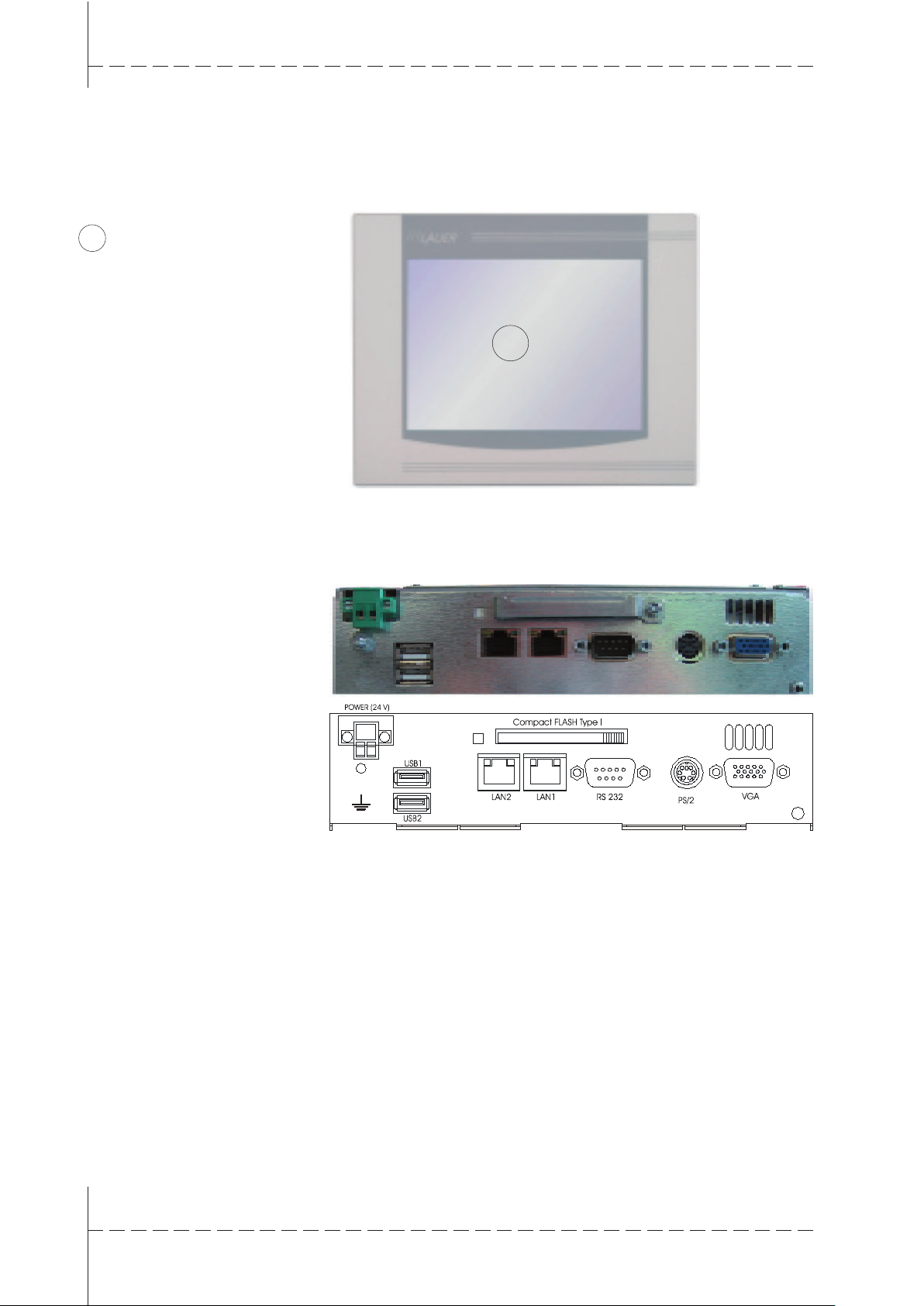
1.1 Operating panel
1
Color TFT resistive touch display
6.4", 8.4", 10.4",12" or 15"
1.2 Slot panel
1
Page 9
© Elektronik-Systeme Lauer GmbH & Co KG • Kelterstr.59 • 72669 Unterensingen • Tel. (07022) 9660-0 • Fax (07022) 9660-103
0-9
1.3 Ports
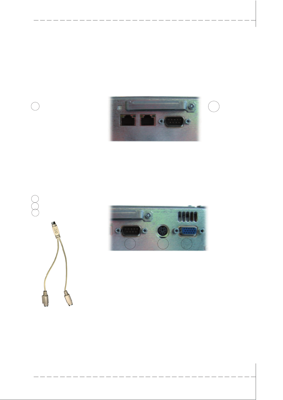
1.3.1 Compact FLASH Slot
Position of the Compact FLASH slot
1 Captive screw
1.3.2 VGA-/COM1-/PS/2 port
The EPC industrial PC is standardly equipped with a Compact FLASH
slot according to CFA standards (Type 1).
1
Warning!
In connection with the EPC, only Compact FLASH cards from the
company SANDISK may be used.
Do not replace the Compact FLASH card unless the PC is switched
off!
1
VGA port
2 COM 1
3 PS/2 mouse/keyboard
PS2 adapter cable for mouse and keyboard
2
The debug port is designed as a serial port for all standard embedded
PCs.
This port can be configured as a debug port to support program
development.
Warning!
The COM 1 port is only available if it is activated by software.
The serial port is standardly assigned according to the PC XT/AT!
Warning!
Do not remove the PS/2 mouse and PS/2 keyboard unless the PC is
switched off.
Otherwise, the operating system will not detect these input devices!
3
1
Page 10
© Elektronik-Systeme Lauer GmbH & Co KG • Kelterstr.59 • 72669 Unterensingen • Tel. (07022) 9660-0 • Fax (07022) 9660-103
0-10
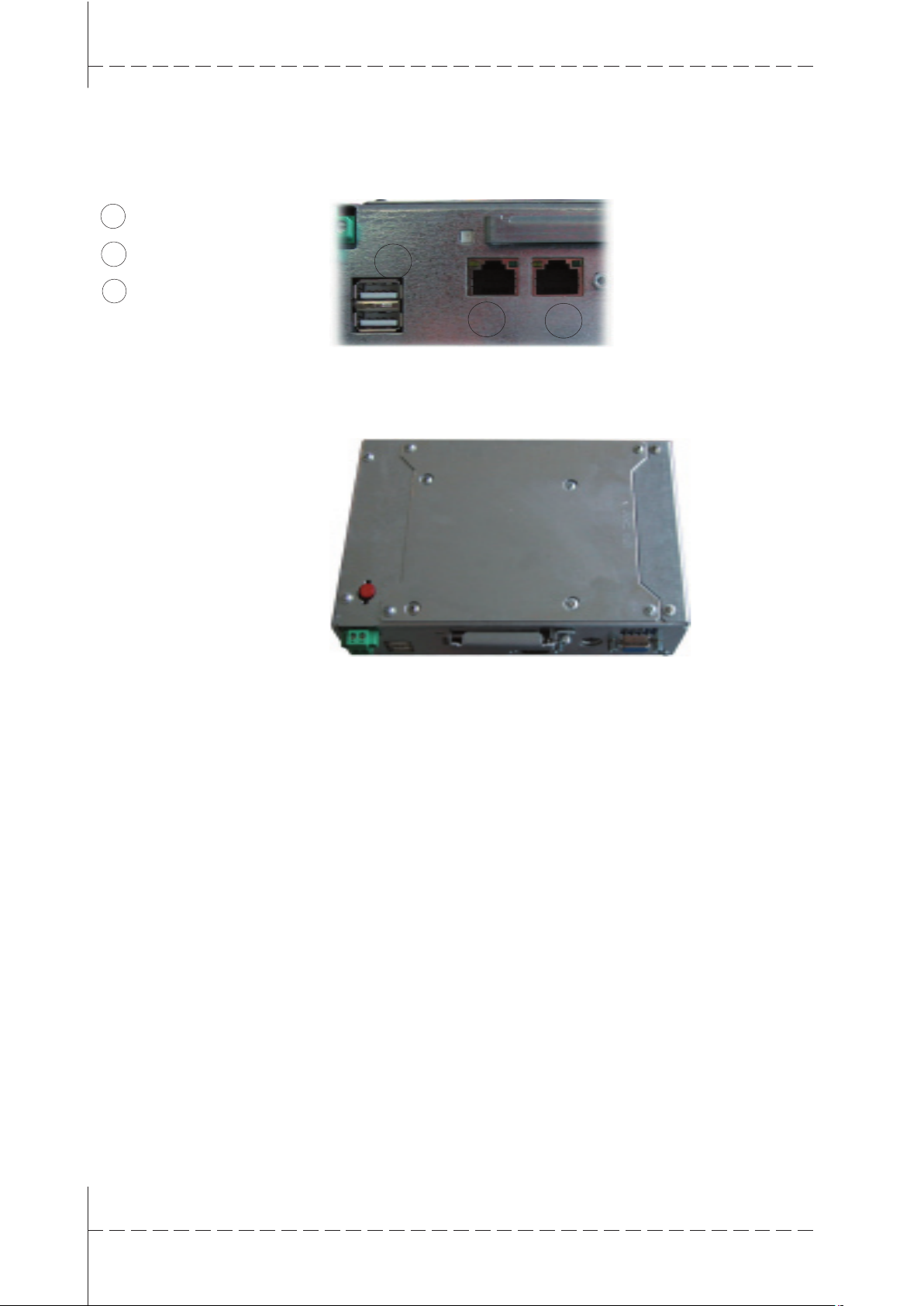
1.3.3 Ethernet, USB
1 Ethernet 1 (RJ45)
2 Ethernet 2 (RJ45)
3 USB 1/2
1.4 Back side
3
2
1
Page 11
© Elektronik-Systeme Lauer GmbH & Co KG • Kelterstr.59 • 72669 Unterensingen • Tel. (07022) 9660-0 • Fax (07022) 9660-103
0-11
2 Start-up
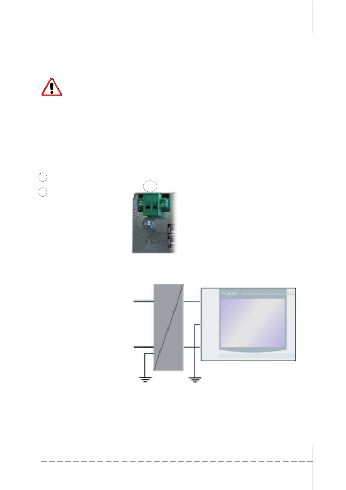
2.1 Power supply
1 24V voltage supply
Warning!
Only operate the embedded PC using protective extra-low voltage
according to EN60950!
The transformer must meet the EN60742 standard!
Check the power supply to ensure it corresponds to the type plate.
Prior to system start-up, check all cable connections.
Make sure that all voltages and signals meet the relevant
specifications.
The 0V supply voltage connection to the housing (earth) is a low-
impedance connection.
2 Earth screw
Power supply arrangement
1
2
The power supply is provided by means of a two-pronged plug-in
connector (Phoenix MST BT 2,5/2).
230 VAC
+ 24 V
230 VAC
0 V
24 V DC
Page 12

© Elektronik-Systeme Lauer GmbH & Co KG • Kelterstr.59 • 72669 Unterensingen • Tel. (07022) 9660-0 • Fax (07022) 9660-103
0-12
2.2 Grounding diagram
In order to reliably prevent electrical disruptions,
please note the following points:
• Connect the PC and control cabinet as close to a central grounding
point as possible.
• Make sure inductive connection between the computer and the
control cabinet is as low as possible.
• All data cables connected to the computer have to be shielded
cables.
• The shields have to be grounded on both ends. There must be a
low-impedance connection between the connected systems. Rule
out high equalizing currents through the shielding resulting from
potential differences.
• The grounding connection with a green-yellow cable must be designed with at least a 4 mm² cross-section.
2.3 Installation
Installation The industrial PC has to be installed in an HF- impermeable housing or
metal control cabinet.
In order to dissipate the heat emanating from the PC, 100 mm on three
sides of the PC must be kept clear so air can freely circulate.
The PC is assembled by screwing in eight hexagon nuts.
Caution!
Damage to the PC possible!
Front-end IP65 degree of protection is only guaranteed if the sealing sits
correctly on the front plate.
Once installed, 100 mm on three sides of the PC must be kept clear so
air can freely circulate
Caution!
The use of Compact Flash Card’s from different manufacturers can lead
to errors.
When using an internal and external Compact Flash card, only use cards
from the same manufacturer (same type and same size)
2.4 Switch on the PC
Start-up procedure The EPC boots up and loads the operating system.
Page 13

© Elektronik-Systeme Lauer GmbH & Co KG • Kelterstr.59 • 72669 Unterensingen • Tel. (07022) 9660-0 • Fax (07022) 9660-103
0-13
3 Service
Tools All you need to assemble the PC is a 2.0 hexagon socket as well as a
5.5 socket wrench. A small screwdriver and pliers are also helpful (see
illustrations).
Preparation Disconnect the PC from the power supply!
Danger!
Make sure that your electro-static underlay is not able to damage the
front of the EPC.
Open PC Only authorized personnel may perform work on the open PC. Within the
warranty period, the hardware may only be updated with memory and
plug-in cards.
Caution!
The PC contains electronic components that can be disrupted by electro-
static charges.
Therefore, you have to take precautionary measures when opening the
PC. You can find these in the guidelines for electro-statically discharge
sensitive devices (EDSD guidelines).
Page 14

© Elektronik-Systeme Lauer GmbH & Co KG • Kelterstr.59 • 72669 Unterensingen • Tel. (07022) 9660-0 • Fax (07022) 9660-103
0-14
3.1 Replacing the external CFC
To replace the external CFC, loosen the locking system using a socket
wrench.
Then turn the locking bracket upward to replace the CFC.
Page 15

© Elektronik-Systeme Lauer GmbH & Co KG • Kelterstr.59 • 72669 Unterensingen • Tel. (07022) 9660-0 • Fax (07022) 9660-103
0-15
3.2 Replacing the internal CFC
To replace the internal CFC, remove the cover.
Loosen the screws indicated in the illustration and remove the cover
plate.
The internal CFC slot is then visible.
Press on the release levers (see arrows) and replace the CFC.
Afterwards, simply screw the cover plate back on.
Page 16

© Elektronik-Systeme Lauer GmbH & Co KG • Kelterstr.59 • 72669 Unterensingen • Tel. (07022) 9660-0 • Fax (07022) 9660-103
0-16
3.3 Replacing the fuse
If the fuse has to be replaced, it can easily be removed using a pair of
pliers.
Replacing a new fuse T2,5A (item no.: 200.140.0110).
Page 17

© Elektronik-Systeme Lauer GmbH & Co KG • Kelterstr.59 • 72669 Unterensingen • Tel. (07022) 9660-0 • Fax (07022) 9660-103
0-17
3.4 Changing the battery
If the battery needs to be replaced, you have to remove the back cover
plate. To do so, loosen the screws as shown.
Remove the back cover plate.
The battery can be conveniently removed by hand.
Please note that the BIOS settings may disappear when changing the
battery.
Page 18

© Elektronik-Systeme Lauer GmbH & Co KG • Kelterstr.59 • 72669 Unterensingen • Tel. (07022) 9660-0 • Fax (07022) 9660-103
0-18
Insert the new lithium 3V battery (item no.: 200.300.0070) with lettering
facing up and screw the back plate back on firmly.
Page 19

© Elektronik-Systeme Lauer GmbH & Co KG • Kelterstr.59 • 72669 Unterensingen • Tel. (07022) 9660-0 • Fax (07022) 9660-103
0-19
T Technical data
T1 Mechanical dimensions
Air circulation To dissipate the heat emanating from the PC, 100 mm on three sides of
the PC must be kept clear so air can freely circulate.
T1.1 EPC LX 640 exterior/installation dimensions
Front plate Width 211 mm
Height 156 mm
Cut out dimensions Width 197 mm
Height 142 mm
Installation depth 70 mm
Weight approx. 1 kg
Front panel cut-out for installation
W x H cut-out
197.0 mm x 142.0 mm
1. Type of attachment: with 6 pieces.
Holding blocks made of aluminum or
plastic with threaded pins
M5x30, DIN 914, with nib and
hexagon socket, galvanized
Page 20

© Elektronik-Systeme Lauer GmbH & Co KG • Kelterstr.59 • 72669 Unterensingen • Tel. (07022) 9660-0 • Fax (07022) 9660-103
0-20
T1.2 EPC LX 640 Unit dimensions
view of the unit underneath
lateral view unit rear view lateral view
view of the equipment top side
Page 21

© Elektronik-Systeme Lauer GmbH & Co KG • Kelterstr.59 • 72669 Unterensingen • Tel. (07022) 9660-0 • Fax (07022) 9660-103
0-21
T1.3 EPC LX 840 Exterior/installation dimensions
Front plate Width 252 mm
Height 190 mm
Cut out dimensions Width 232 mm
Height 170 mm
Installation depth 61 mm
Weight approx. 1.9 kg
Page 22

© Elektronik-Systeme Lauer GmbH & Co KG • Kelterstr.59 • 72669 Unterensingen • Tel. (07022) 9660-0 • Fax (07022) 9660-103
0-22
T1.4.1 EPC LX 840 Unit dimensions
view of the unit underneath
lateral view unit rear view lateral view
view of the equipment top side
Page 23

© Elektronik-Systeme Lauer GmbH & Co KG • Kelterstr.59 • 72669 Unterensingen • Tel. (07022) 9660-0 • Fax (07022) 9660-103
0-23
with Dual CAN IXXAT (optional)
T1.4.2 EPC LX 840 nautic Unit dimensions with Dual CAN IXKAT
lateral view unit rear view lateral view
view of the unit underneath
view of the equipment top side
Page 24

© Elektronik-Systeme Lauer GmbH & Co KG • Kelterstr.59 • 72669 Unterensingen • Tel. (07022) 9660-0 • Fax (07022) 9660-103
0-24
Data sheet EPC-GX 840tc nautic
with integrated buzzer (optional)
T1.4.3 EPC LX 840 nautic Unit dimensions with integrated Buzzer
view of the unit underneath
lateral view unit rear view lateral view
view of the equipment top side
Page 25

© Elektronik-Systeme Lauer GmbH & Co KG • Kelterstr.59 • 72669 Unterensingen • Tel. (07022) 9660-0 • Fax (07022) 9660-103
0-25
T1.5 EPC LX 1000 Exterior/installation dimensions
Front plate Width 318 mm
Height 244 mm
Cut out dimensions Width 303 mm
Height 228 mm
Installation depth 77 mm
Weight approx. 2.8 kg
Page 26

© Elektronik-Systeme Lauer GmbH & Co KG • Kelterstr.59 • 72669 Unterensingen • Tel. (07022) 9660-0 • Fax (07022) 9660-103
0-26
T1.6.1 EPC LX 1000 Unit dimensions
view of the unit underneath
lateral view unit rear view lateral view
view of the equipment top side
Page 27

© Elektronik-Systeme Lauer GmbH & Co KG • Kelterstr.59 • 72669 Unterensingen • Tel. (07022) 9660-0 • Fax (07022) 9660-103
0-27
T1.6.2 EPC LX 1000 nautic Unit dimensions
view of the unit underneath
lateral view unit rear view lateral view
view of the equipment top side
Page 28

© Elektronik-Systeme Lauer GmbH & Co KG • Kelterstr.59 • 72669 Unterensingen • Tel. (07022) 9660-0 • Fax (07022) 9660-103
0-28
T1.7 EPC LX 1200 Exterior/installation dimensions
Front plate Width 364 mm
Height 296 mm
Cut out dimensions Width 345 mm
Height 277 mm
Installation depth 77 mm
Weight approx. 2.8 kg
Page 29

© Elektronik-Systeme Lauer GmbH & Co KG • Kelterstr.59 • 72669 Unterensingen • Tel. (07022) 9660-0 • Fax (07022) 9660-103
0-29
T1.8 EPC LX 1200 Unit dimensions
view of the unit underneath
lateral view unit rear view lateral view
view of the equipment top side
Page 30

© Elektronik-Systeme Lauer GmbH & Co KG • Kelterstr.59 • 72669 Unterensingen • Tel. (07022) 9660-0 • Fax (07022) 9660-103
0-30
T1.9 EPC LX 1500 Exterior/installation dimensions
Front plate Width 452 mm
Height 357 mm
Cut out dimensions Width 429 mm
Height 334 mm
Installation depth 77 mm
Weight approx. 5.0 kg
Front view
Front dimensions W x H
452.0 x 357.0 mm
Tolerance 0,2 mm
Front panel cut-out
for installation
W x H cut-out
429.0 mm x 334.0 mm
Space for holding blocks
around 15 mm
Space total W x H
459.0 mm x 364.0 mm
Page 31

© Elektronik-Systeme Lauer GmbH & Co KG • Kelterstr.59 • 72669 Unterensingen • Tel. (07022) 9660-0 • Fax (07022) 9660-103
0-31
T1.10 EPC LX 1500 Unit dimensions
view of the unit underneath
lateral view unit rear view lateral view
view of the equipment top side
Page 32

© Elektronik-Systeme Lauer GmbH & Co KG • Kelterstr.59 • 72669 Unterensingen • Tel. (07022) 9660-0 • Fax (07022) 9660-103
0-32
T2 Electrical data
Power supply DC Operating voltage 24 V ± 20%, reverse polarity protected
Fuse 2,5 A delay
Power failure buffering time 1 ms bei 19,2 V (Ub-20%)
Display Display 640 840 1000 1200 1500
Resolution 640x480 640x480 800x600 800x600 1024x768
Charging rate EPC LX Box 0,55 A
EPC LX 640 0,75 A
EPC LX 840 / nautic 0,85 A
EPC LX 1000 / nautic 0,90 A
EPC LX 1200 1,10 A
EPC LX 1500 1,20 A
Touch resistive
CPU unit CPU: On Board AMD Geode LX 800/700(533MHz) CPU
System Memory: 200-pin DDR SDRAM
1GB for DDR333 and 512MB for DDR400
Chipset: AMD LX series + CS5536
I/O Chipset: IT8712/FKX + IT8888G
BIOS: Award 512KB FLASH ROM
Battery: Lithium battery CR 2032
SSD: internal Type II Compact Flash™
Display Chipset: AMD LX series + TI SN75LVDS83
Interfaces Serial: 1x RS232
Ethernet: 2x Realtek RTL8139DL,
10/100Base-TX RJ45 connector
USB: 2x USB2.0
Memory card
external: Type II Compact Flash
Mouse and
keyboard: over Mini DIN PS/2 Y- cabel
Hardware options on PC104 base RS232/TTY RS485/422 MPI
Profibus DP and Profibus-Master
Can Open and Can Open-Master
PC104 Codesys PLC / Can Open-Master
Page 33

© Elektronik-Systeme Lauer GmbH & Co KG • Kelterstr.59 • 72669 Unterensingen • Tel. (07022) 9660-0 • Fax (07022) 9660-103
0-33
T3 Environmental conditions
Surrounding temperature Operating 0 ... 50° C
Operating 0 ... 55° C for nautic Versions
storage -20 ... 60° C
Humidity Operating 10 ... 75%, non-condensing
storage 10 ... 95%, non-condensing
Resistance to
vibration and shock Sinus 2g, 10-500 Hz
Shock 15g, 11 ms
Continuous shock 10g, 16 ms
free fall from 1m height (in packaging), 1 x each axle
Protection front IP 65
back IP 20
EMV/CE Interference
resistance EN 61000-6-2
Interference
radiation EN 61000-6-4
 Loading...