

Page 1

MAEN979B, 2010-08
EPC C2D Nautic
Installation Manual
English
Page 2

Foreword
© Beijer Electronics AB, MAEN979B, 2010-08
Please read the entire installation manual prior to installing and using this equipment. Only qualified
personnel may install, operate or repair this equipment. Beijer Electronics AB, including all its group
companies, is not responsible for modified, altered or renovated equipment. Because the equipment has a
wide range of applications, users must acquire the appropriate knowledge to use the equipment properly
in their specific applications.
Persons responsible for the application and the equipment must themselves ensure that each application
is in compliance with all relevant requirements, standards and legislation in respect to configuration and
safety. Only parts and accessories manufactured according to specifications set by Beijer Electronics AB
may be used.
BEIJER ELECTRONICS AB, INCLUDING ALL ITS GROUP COMPANIES, SHALL NOT BE
LIABLE TO ANYONE FOR ANY DIRECT, INDIRECT, SPECIAL, INCIDENTAL OR CONSEQUENTIAL DAMAGES RESULTING FROM THE INSTALLATION, USE OR REPAIR OF THIS
EQUIPMENT, WHETHER ARISING IN TORT, CONTRACT, OR OTHERWISE. BUYER'S
SOLE REMEDY SHALL BE THE REPAIR, REPLACEMENT, OR REFUND OF PURCHASE
PRICE, AND THE CHOICE OF THE APPLICABLE REMEDY SHALL BE AT THE SOLE DISCRETION OF BEIJER ELECTRONICS AB.
EPC C2D Nautic Installation Manual
Foreword
The EPC C2D Nautic series consists of enhanced Panel IPCs, compatible with
the toughest of maritime environments. Shock and vibration resistant and functional throughout comprehensive temperature changes, the series features a
robust hard-disk drive, fanless CPU and Windows XP as the standard operating
system.
The series also offers the option of modifying a number of its features, affording
a customized version with a flash-memory, fanless chassis and Windows XP
embedded.
The rugged EPC C2D Nautic series provides an open platform solution that can
be utilized with the customer’s choice of software to meet the demands of any
marine environment with high performance reliability that’s built to last.
This manual describes each model and gives instructions on installation, operation and service.
Beijer Electronics, MAEN979B
Page 3

Contents
Contents
1 Safety Precautions................................................................................... 5
1.1 Nautic Approvals and Certificates .......................................................5
1.2 General ...............................................................................................6
1.3 During Installation..............................................................................7
1.4 During Use .........................................................................................7
1.5 Service and Maintenance.....................................................................8
1.6 Dismantling and Scrapping.................................................................8
2 Product Naming ..................................................................................... 9
3 Supplied Equipment ............................................................................. 10
4 Compass Safety Distance ...................................................................... 11
5 Description of Parts.............................................................................. 12
5.1 EPC C2D Nautic..............................................................................12
5.2 Display..............................................................................................13
5.3 Communication Ports .....................................................................14
5.4 Motherboard.....................................................................................15
5.5 Assembly...........................................................................................15
5.6 Power Supply ....................................................................................16
5.7 Earthing System ................................................................................17
5.8 ATX Power Switch............................................................................17
5.9 ATX Remote Connector ...................................................................18
5.10 Compact Flash Memory Card...........................................................18
6 Operation ............................................................................................. 19
6.1 Operating System..............................................................................19
6.2 Default BIOS Settings.......................................................................20
6.3 Important Items Regarding Software Installation ..............................23
6.4 Graphic Board Installation ................................................................24
6.5 Touch Screen Installation..................................................................25
6.6 Installation of LAN-/Network Card ..................................................29
Beijer Electronics, MAEN979B
Page 4

Contents
7 Service .................................................................................................. 31
7.1 Introduction......................................................................................31
7.1.1 Tools .................................................................................................31
7.1.2 Preparation........................................................................................31
7.1.3 Opening the EPC..............................................................................31
7.2 Changing the Fan Filter.....................................................................32
7.3 PCI-board Installation.......................................................................32
7.4 Cable Fixing Points ...........................................................................36
8 Technical Data ..................................................................................... 37
9 Drawings .............................................................................................. 39
9.1 EPC T150/150 C2D Nautic Front View .........................................39
9.2 EPC T150/150 C2D Nautic Cut Out Drawing................................40
9.3 EPC T150/150 C2D Nautic Outline Drawings................................41
9.4 EPC T170/170 C2D Nautic Front View .........................................42
9.5 EPC T170/170 C2D Nautic Cut Out Drawing................................43
9.6 EPC T170/170 C2D Nautic Outline Drawings................................44
9.7 EPC T190/190 C2D Nautic Front View .........................................45
9.8 EPC T190/190 C2D Nautic Cut Out Drawing................................46
9.9 EPC T190/190 C2D Nautic Outline Drawings................................47
9.10 EPC Box C2D Nautic Outline Drawings..........................................48
Beijer Electronics, MAEN979B
Page 5

Safety Precautions
1Safety Precautions
Both the installer and the owner and/or operator of the EPC must read and understand this installation manual.
1.1 Nautic Approvals and Certificates
The EPC C2D Nautic series are certified according to the following list. Some
approvals are in progress. Please visit our web site for the latest information.
Model CE LR BV GL DNV ABS RS
EPC T150/150 C2D Nautic XXXXXXX X*
EPC T170/170 C2D Nautic XXXXXXX X*
EPC T190/190 C2D Nautic XXXXXXX X*
EPC Box C2D Nautic XXXXXXX X*
* Also for bridge applications
Approval/Certificate Abbreviation
Conformité Européenne CE
Lloyd’s Register LR
Bureau Veritas BV
Germanischer L l oy d GL
Det Norske Veritas DNV
American Bureau of Shipping ABS
Russian Maritime Re gister of Sh ippin g RS
EN
60945
Beijer Electronics, MAEN979B 5
Page 6

Safety Precautions
1.2 General
– The EPC is intended for industrial use only.
– The EPC is constructed for naval applications and for indoor use according
to IEC 60945.
– Read the safety precautions carefully.
– Check the delivery for transportation damage. If damage is found, notify the
supplier as soon as possible.
– Do not use the EPC in an environment with high explosive hazards.
– The supplier is not responsible for modified, altered or reconstructed equip-
ment.
– Use only parts and accessories manufactured according to specifications of the
supplier.
– Read the installation and operating instructions carefully before installing, us-
ing or repairing the EPC.
– Never allow fluids, metal filings or wiring debris to enter any openings in the
EPC. This may cause fire or electrical shock.
– Only qualified personnel may operate the EPC.
– Storing the EPC where the temperature is lower/higher than recommended
in this manual can cause the LCD display liquid to congeal/become isotopic.
– The LCD display liquid contains a powerful irritant. In case of skin contact,
wash immediately with plenty of water. In case of eye contact, hold the eye
open, flush with plenty of water and get medical attention.
– The figures in this manual serves an illustrative purpose. Because of the many
variables associated with any particular installation, the supplier cannot assume responsibility for actual use based on the figures.
– The supplier neither guarantees that the EPC is suitable for your particular
application, nor assumes responsibility for your product design, installation
or operation.
6 Beijer Electronics, MAEN979B
Page 7

Safety Precautions
1.3 During Installation
– The EPC is designed for stationary installation on a plane surface, where the
following conditions are fulfilled:
• no high explosive risks
• no strong magnetic fields
•no direct sunlight
• no large, sudden temperature changes
– Install the EPC according to the accompanying installation instructions.
– Ground the EPC according to the accompanying installation instructions.
– Only qualified personnel may install the EPC.
– Separate the high voltage, signal and supply cables.
– Make sure that the voltage and polarity of the power source is correct before
connecting the EPC to the power outlet.
– Peripheral equipment must be appropriate for the application and location.
– The controlling transformer has to comply with EN60742.
1.4 During Use
– Keep the EPC clean.
– Emergency stop and other safety functions may not be controlled from the
EPC.
– Do not use too much force or sharp objects when touching the keys, touch
screen etc.
Beijer Electronics, MAEN979B 7
Page 8

Safety Precautions
1.5 Service and Maintenance
– Only qualified personnel should carry out repairs.
– The agreed warranty applies.
– Before carrying out any cleaning or maintenance operations, disconnect the
equipment from the electrical supply.
– Clean the display and surrounding front cover with a soft cloth and mild de-
tergent.
– Replacing the battery incorrectly may result in explosion. Only use batteries
recommended by the supplier.
1.6 Dismantling and Scrapping
– The EPC or parts thereof shall be recycled according to local regulations.
– The following components contain substances that might be hazardous to
health and the environment: lithium battery, electrolytic capacitor and display.
8 Beijer Electronics, MAEN979B
Page 9

Product Naming
2Product Naming
The naming of the computers is constructed with a number of parameters that
indicate the characteristics of each model, for example EPC T170 C2D Nautic
AC according to below:
EPC T 170 C2D Nautic AC
Computer
series
There is a variant without display; EPC C2D Box Nautic AC:
EPC C2D Box Nautic AC
Computer
series
Optional touch
screen
Processor type No display Main
Screen
size
Processor
type
usage
Main
usage
Type of
power supply
power supply
Type of
Beijer Electronics, MAEN979B 9
Page 10

Supplied Equipment
3 Supplied Equipment
Part Description
CD; operating system CD with operating syst em .
CD; driver software Driver software CD for all pr e-i n s ta l l ed com po n ents
such as mother board, touch screen, keyboard etc.
Power cable Standard power cable (European or US standard) for
units with 230 V AC power supply.
Length: approximately 3.0 m.
24 V DC units are delivered without cable.
A variety of cables are available separately.
Installation manual This manual describes specific information about
Beijer Electronics products only – not about third
party components.
Note:
Separate documentation of thir d pa r ty compo n ents is
included on the enclosed driver software CD + as
printed documentation.
Mounting kit Screws, nuts etc.
Sticker Device sticker with device name and part number
Note:
Place the sticker on the front of the device when
mounting, to identify device while installing and at
startup.
10 Beijer Electronics, MAEN979B
Page 11

Compass Safety Distance
4Compass Safety Distance
The EPC C2D Nautics are certified according to EN 60945 for bridge applications. The tests include a compass safety distance test.
Electrical devices, such as the EPC C2D Nautic, must be kept in a safe distance
to a compass in operation according to the following table:
Compass type Minimum distance to the EPC C2D Nautic
Steering compass 1 meter in all directions
Emergency compass
Standard compass 1.45 meter in all directions
Beijer Electronics, MAEN979B 11
Page 12
Description of Parts
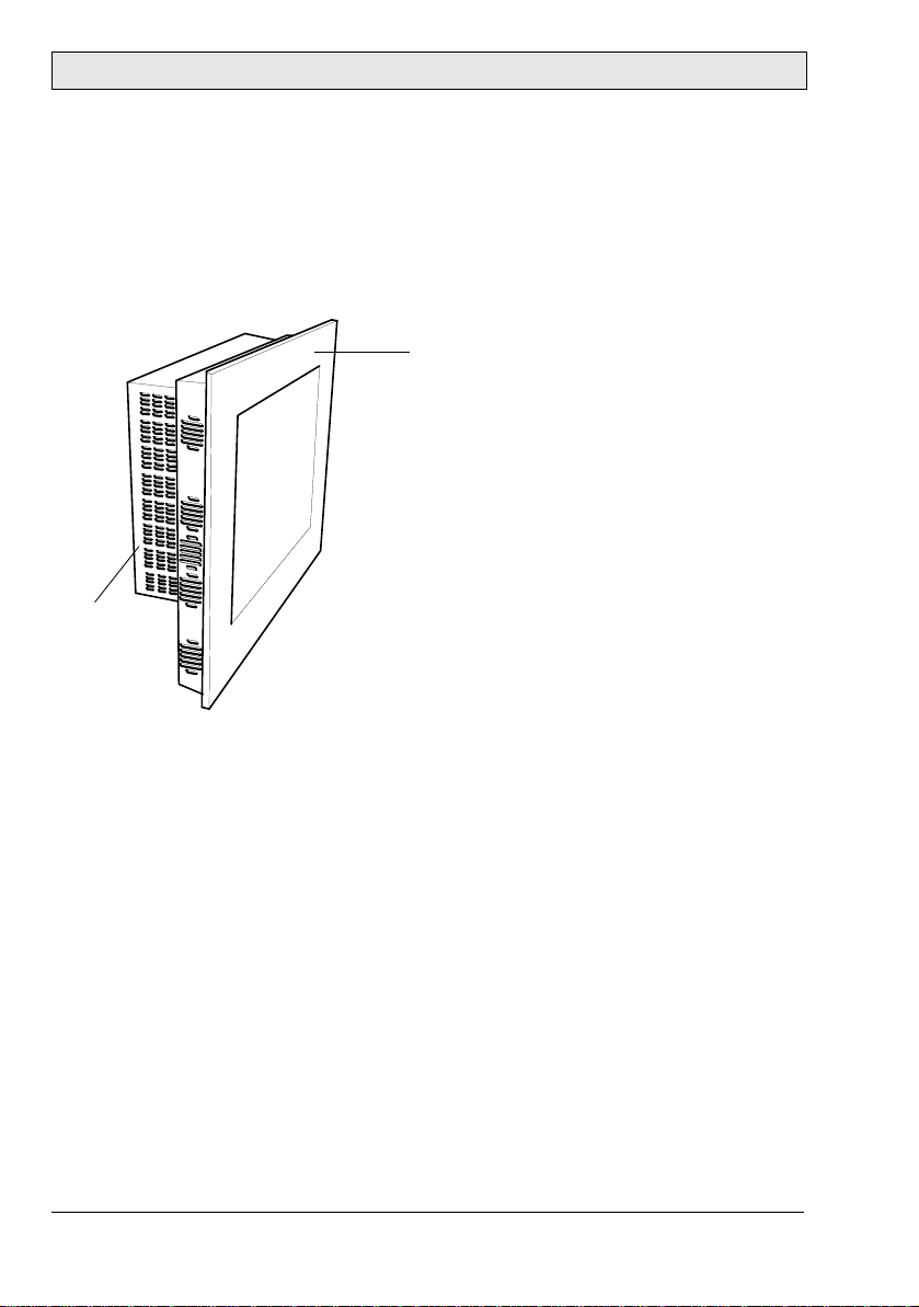
Front unit
PC unit
5Description of Parts
5.1 EPC C2D Nautic
The EPC C2D Nautic consists of a Front unit and a PC unit. These are installed
in the same way independent of the display size.
The EPC Box C2D Nautic consists of the PC unit only.
12 Beijer Electronics, MAEN979B
Page 13
Description of Parts
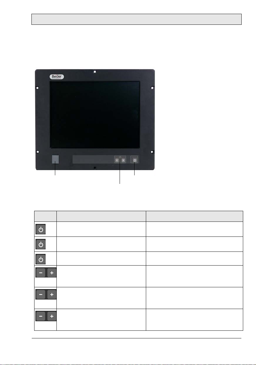
USB port
Power button
Dimmer buttons
5.2 Display
Display sizes 15", 17" and 19" are available, as well as the EPC Box C2D Nautic
without display.
The front includes a USB-port under hatch, a power button with a LED, and a
set of dimmer buttons. The buttons are explained below:
Button Instruction Description
Press the power b u tton quickly Turns the EPC off in a controll ed way
(as from the Windows Start menu)
Press the power button for longer
than 4 seconds
Press the power button again Turns the EPC o n
Press - (brightness down) on the
dimmer button (single step or automatic repeating after one second)
Press + (brightness up) on the
dimmer button (single step or automatic repeating after one second)
Press + and - simultaneously for
more than one second
Forces the EPC to be turned off
Makes the display dar k e r
Makes the display bri g h t er
Turn s o n f u l l b r ightness qui ckly
(default - may be configured according
to RBC software manual MAEN986)
Beijer Electronics, MAEN979B 13
Page 14
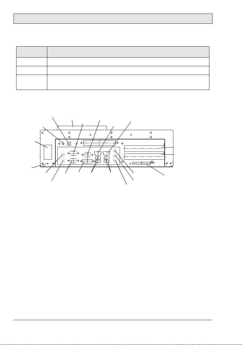
Description of Parts
Power
ATX switch
PS/2 mouse
PS/2 keyboard
COM1
COM2
DVI-1
VGA
Compact Flash slot
Mic in
supply
PCI slot 1
USB 1-2
LAN 1
Earth
USB 3-4
LAN 2
Line in
Line out
PCI slot 2
Fan
ATX remote
The power LED can assume the following statuses:
LED Description
Green Normal operation
Red No input signal available or the screen is in energy saving mode
- The EPC is turned off or the screen is dimmed to 0 (lowest value,
darkest possible)
5.3 Communication Ports
14 Beijer Electronics, MAEN979B
Page 15

Description of Parts
5.4 Motherboard
The EPC C2D Nautic has 2 SODIMM slots for main storage and 2 PCI-slots.
Further details on the motherboard can be found in a separate manual, included
in the delivery.
Note:
The quality of the memory module may influence the system stability . When updating
the memory module, or adding a second one, please only use memory modules approved by Beijer Electronics. Memory modules are electrostatic sensitive components. Relevant p rotective meas ures (earth) have to be considered during assembly/
disassembly. ESD-protective measures are to be considered when opening and working on the EPC.
5.5 Assembly
A free space of 100 mm, for air circulation, has to be provided around the EPC,
to dissipate the heat generated during operation.
The EPC C2D Nautic is assembled with items included in the supplied mounting kit.
Note:
Possible risk of damage to the EPC!
Protecti on class IP65 for the front panel is only gua ranteed with a perfect fitting s eal.
Pay attention to the torque when fixing the front panel.
Beijer Electronics, MAEN979B 15
Page 16
Description of Parts
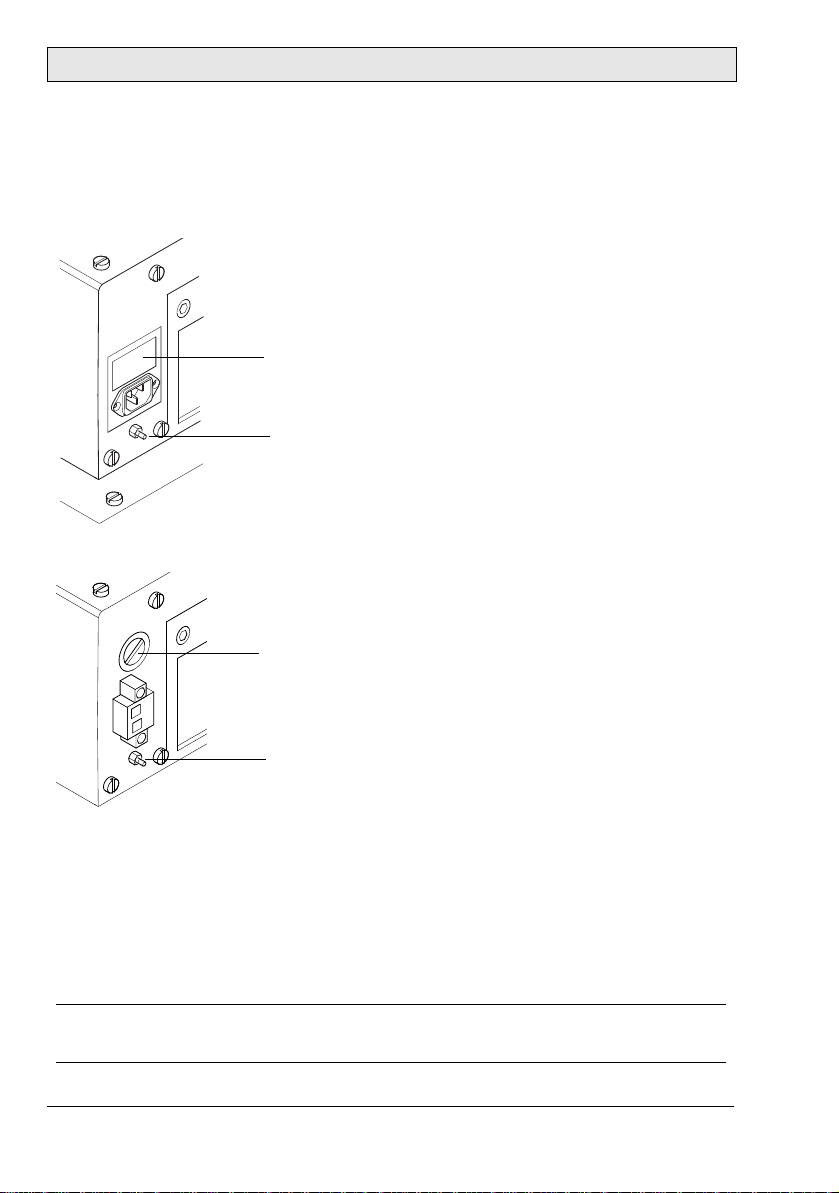
Earth screw
Fuse 1 A
Earth screw
Fuse 6.3 A
5.6 Power Supply
The EPC C2D Nautic is available with 230 V AC or 24 V DC power system.
230 V AC Power Supply Connection with Integrated Fuse
24 V DC Power Supply Connection
The power supply for 24 V DC is carried out via a double-pole connector
(Phoenix MST BT 2,5/2).
The EPC C2D Nautic is certified for the connection to protective grounded
power supply according to EN60950. The EPC Box C2D Nautic can also be
operated with extra low voltage in accordance with EN60950. The controlling
transformer has to comply with EN60742.
Note:
Check the power supply system with the relevant data on the type plate.
16 Beijer Electronics, MAEN979B
Page 17

Description of Parts
5.7 Earthing System
The following items have to be observed to guarantee a safe dissipation of electronic interference:
– The EPC and switch board have to be connected to the nearest possible cen-
tral earthing point.
– Make sure of a possibly low inductive connection between EPC and switch
board.
– All data cables connected to the EPC have to be of the shielded type.
– The screens have to be earthed on both sides. A low ohm connection between
the connected systems is essential. Avoid high equalizing currents through the
cable screen due to voltage fluctuations.
– The earthing connection is to be carried out with min. 4 mm² cross section.
5.8 ATX Power Switch
Power packs, main boards and operation systems are used in the EPC C2D Nautic, using up to date PC-technologies such as ATX and ACPI. Switching on the
EPC is done in accordance with ATX specification via the ATX power switch
(the red button next to the power supply).
Should a correct automatic booting not function then this can have the following reason:
In the BIOS settings, the option PWRON After PWR-Fail in the Integrated
Peripherals/Super IO Device menu must be enabled, i.e. On. See also section
6.2 Default BIOS Settings.
The operating system must be ended correctly using the Shut down command
from the operating system menu (Windows start menu), so that the operating
system of the EPC is shut down. The EPC must not be switched off while the
operating system is still running.
The power pack now has to be separated from the power supply for a minimum
of 15 seconds prior to a re-start. During the booting process the main voltage
may not fall (not even for a short time) below the permitted value.
A manual actuation of the ATX power switch, i.e. to start the BIOS menu automatically to check and confirm correct settings, can be necessary if the system
registers an error during shut-down or booting. This is not a malfunction but a
safety feature.
Beijer Electronics, MAEN979B 17
Page 18

Description of Parts
5.9 ATX Remote Connector
The ATX remote terminal is a double-pole connector close to the red ATX power switch button. It is parallel connected to the button. An external push-button
switch or a relay contact can be connected to the ATX remote connector.
5.10 Compact Flash Memory Card
An external Compact Flash memory card can be used for data storage. Some
EPC models also allow mounting an internal Compact Flash memory card as a
boot-up device, or for data storage.
Note:
Only Compact Flash cards distributed by Beijer Electronics may be used. Third party products may cause system malfunction or performance loss.
If a Compact Flash memory card is mounted in/removed from a running EPC,
the EPC must be restarted in order to detect the system change.
Booting from a Compact Flash Card
Follow the instructions below, in order to boot the EPC from an internal Compact Flash card:
– Make sure that the Compact Flash card is used as local drive. Standard Com-
pact Flash cards are available only as removeable drives for data storage.
– Confirm that the Compact Flash card is set as first boot device in the BIOS
in order to boot the operation system from it.
– Removing the Compact Flash card while the EPC is running may damage the
operating system.
18 Beijer Electronics, MAEN979B
Page 19

Operation
6Operation
6.1 Operating System
The EPC C2D Nautic is delivered with Windows XP operating system.
The operating system and other programs are installed on drive “C:”.
Drive “D:” contains all data required for a new installation (drivers and operation system) and may also be used for user data (beneficial for example for data
backup).
Beijer Electronics, MAEN979B 19
Page 20
Operation
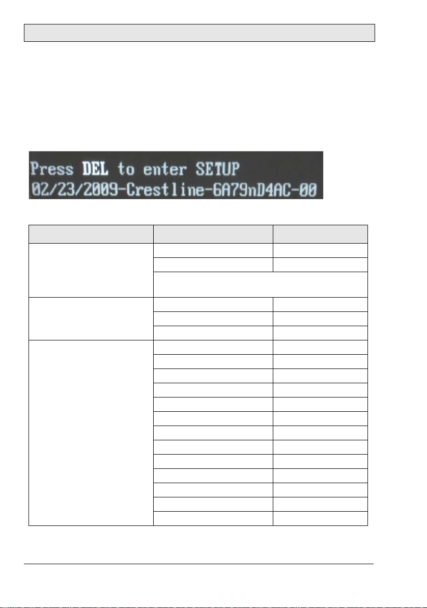
6.2 Default BIOS Settings
The BIOS settings may need to be checked or altered if the system becomes instable.
To start the setup: Switch on the EPC and press the [DEL] button, according to
the first screen image.
Selecting Load Optimized Defaults loads the following settings.
Menu Menu item Setting
Standard CMOS Features Date Current date
Time Current time
Check that all IDE-Devices (HD, CD and CF) are
correctly recognized
Advanced BIOS Features
CPU Features
Advanced BIOS Features Hard Disk Boot Priority Default
Execute Disable Bit Enabled
Virtualization Technology Enabled
Core Multi-Processing Enabled
Virus Warning Disabled
Quick Power On Self Test Enabled
First Boot Device Harddisk
Second Boot Device Harddisk
Third Boot Device Disabled
Boot Other Device Disabled
Boot Up NumLock Status On
Gate A20 Option Fast
Security Option Setup
MPS Version Control For OS 1.4
Report No FDD For Win95 No
Small Logo (EPA) Show Disabled
20 Beijer Electronics, MAEN979B
Page 21

Menu Menu item Setting
Advanced Chipset Features System Bios Cachea ble Enabled
On Chip Frame Buffer Size 8 MB
DVMT Mode DVMT
DVMT / Fixed Memory Size 128 MB
Boot Display Auto
Panel Number
15"
17"
19"
Integrated Peripherals
On Chip IDE Device
Integrated Peripherals
Onboard Device
Integrated Peripherals
Super IO
Integrated Peripherals
USB Device Setting
Powe r Management Setup PCI Express PME Disabled
IDE HDD Block Mode Enabled
IDE DMA transfer access Enabled
SATA Mode IDE
OnChipSerial ATA Enhanced Mode
Onboard LAN1 control Auto
Onboard LAN2 control Auto
Onboard LAN ROM control Disabled
Power ON Functi on Button only
Onboard Serial Port1 3F8/IRQ4
Onboard Serial Port2 2F8/IRQ3
PWRON After PWR-Fail On
Watch Dog Timer Select Disabled
USB 1.0 Controller Enabled
USB 2.0 Controller Enabled
USB Storage Function Enabled
USB Mass Storage Device
Boot setting
ACPI Suspend Type S1
Soft-Off by PWR-BTTN Instant-Off
Wake-Up by PCI Card Disabled
Power On by Ring Disabled
Resume by Alarm Disa bled
12: 1024x768 24 bit
13: 1280x1024 48 bit
13: 1280x1024 48 bit
Auto mode
Operation
Beijer Electronics, MAEN979B 21
Page 22

Operation
Menu Menu item Setting
PNP / PCI Configuration Init Display First Onboard
Reset Configuration Data Disabled
PCI/VGA Palette Snoop Disabled
INT Pin 1 Assignment Auto
INT Pin 2 Assignment Auto
INT Pin 3 Assignment Auto
INT Pin 4 Assignment Auto
INT Pin 5 Assignment Auto
INT Pin 6 Assignment Auto
INT Pin 7 Assignment Auto
INT Pin 8 Assignment Auto
Frequency Voltage Control Auto Detect PCI / clk Enabled
Spread Spectrum Disabled
22 Beijer Electronics, MAEN979B
Page 23

Operation
6.3 Important Items Regarding
Software Installation
The included driver CD includes all drivers needed for a successful reinstallation
of the EPC. Since the EPC is not equipped with a CD/DVD player, an external
USB CD/DVD player has to be used.
The drivers are also available on the “D:” drive.
When the CD is loaded, a menu is displayed for selection of driver installation,
displaying manuals etc. Follow the steps below in the specified order, when reinstalling the system:
1. Install the chipset driver.
2. Install the graphic drivers.
3. Install the touch screen drivers.
4. Install the network drivers.
Note:
To avoid alw ays having to re-start the install a ti o n procedur e of the operating system, we recommend making an image of the new hard disk (using e.g. Norton Ghost,
Drive Image etc.). Then you can always fall back on the operational image, if needed.
Note:
After operating the system for the first time we recommend that you make start
discs (emergency discs). These might be required to restore a n operational system.
Additionally, we recommend making backup copies of your own data and applications.
Beijer Electronics, MAEN979B 23
Page 24

Operation
6.4 Graphic Board Installation
After finalizing the Windows installation (chipset driver) and re-starting the system, terminate the automatic driver search for the graphic board driver and use
the installation CD instead.
Note:
The graphic driver will be installed twice.
5. After finishing the installation and re-starting the EPC, the following
entries are available under the Display icon in the Control Panel, or in the
display properties.
24 Beijer Electronics, MAEN979B
Page 25

Operation
6.5 Touch Screen Installation
Note:
Make sure to use a touch driver of version 6.31.a or higher.
1. Start the touch screen installation from the driver CD, follow the instruc-
tions on the screen and press Next:
Beijer Electronics, MAEN979B 25
Page 26
Operation
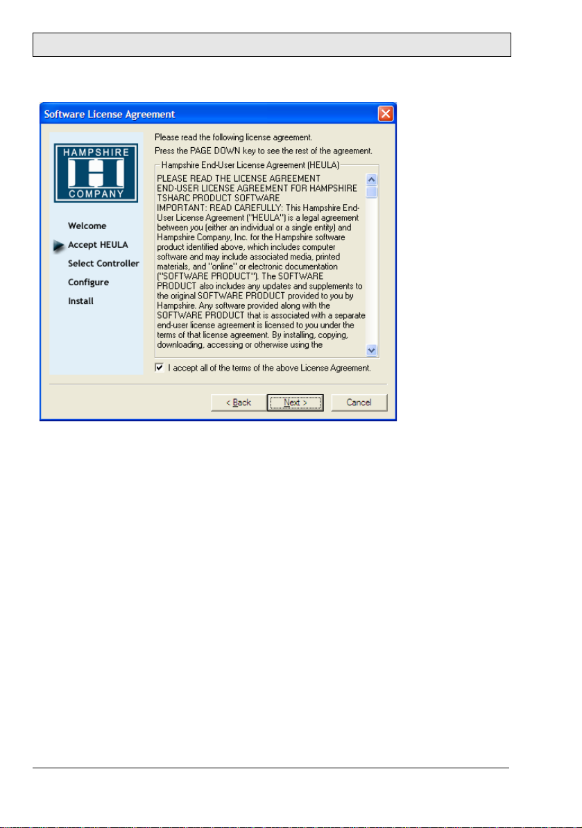
2. Accept the license agreement.
26 Beijer Electronics, MAEN979B
Page 27
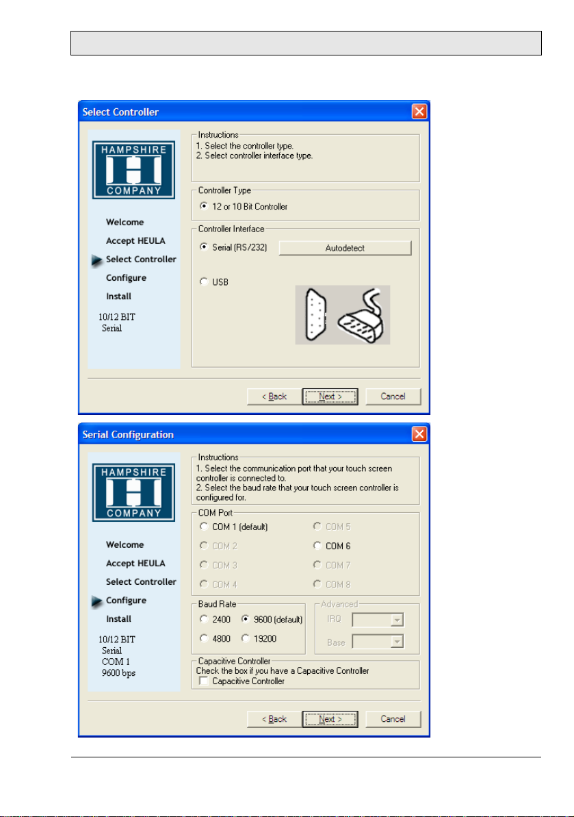
3. Select Autodetect or manually select the technical connection data.
Operation
Beijer Electronics, MAEN979B 27
Page 28

Operation
4. Press Finish and follow the instructions for a re-start.
5. After a re-start of the operating system you will find Hampshire Control
Panel among the programs.
6. Calibrate the touch screen with your finger or with a rounded pointed
touch pen.
28 Beijer Electronics, MAEN979B
Page 29

Operation
6.6 Installation of LAN-/Network Card
After installing the operating system and the chipset driver, the system automatically creates a link to a network connection. You will find a network icon on the
lower right-hand side of the task bar.
1. To install the second network card, follow the instructions on the driver
CD.
2. Confirm each installation step and re-start the EPC at the end of the installation.
3. After the re-start two new network icons appear in the right hand side lower
task bar.
4. You can now configure both network cards to your own requirements (IPaddress etc.) via the system control.
5. Via the MS-DOS window, under Start/All Programs/Accessories/
Command prompt, you can set a “connection PING” to test your connections to the server and other PC’s.
(for example: C:\ping 192.168.5.100).
Beijer Electronics, MAEN979B 29
Page 30

Operation
30 Beijer Electronics, MAEN979B
Page 31
Service
7Service
7.1 Introduction
Only spare parts recommended by Beijer Electronics may be used.
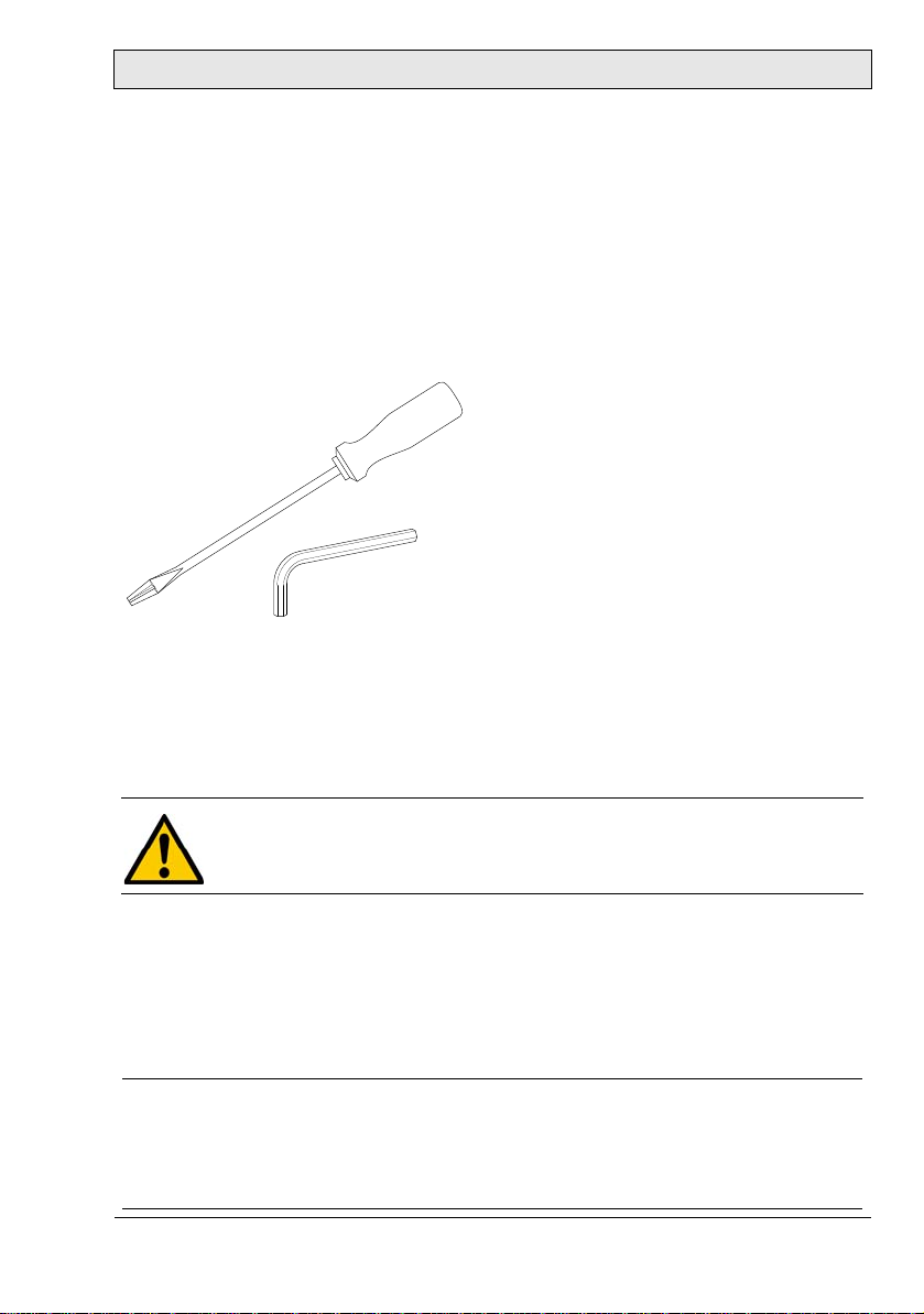
7.1.1 Tools
You can carry out the disassembly and assembly with an 2.5 mm Allen key and
a Phillips head screwdriver, size 3.
7.1.2 Preparation
Disconnect the EPC from the power supply.
Attention! Deadly Peril!
Make sure that your electr ostatic pa d does not damage the f ront panel
of the EPC.
7.1.3 Opening the EPC
All operations to the opened EPC may only be carried out by authorized personnel. Only the expansion of hardware with memory and plug-in-cards is permissible within the defects liability period.
Note:
Inside the EPC there are electronic components which can be destroyed by electrostatic charges. Therefore cautionary measures have to be taken from the moment the EPC is opened. These can be found in the guidelines for electrostatic
endangered components (EGB-guidelines).
Beijer Electronics, MAEN979B 31
Page 32
Service
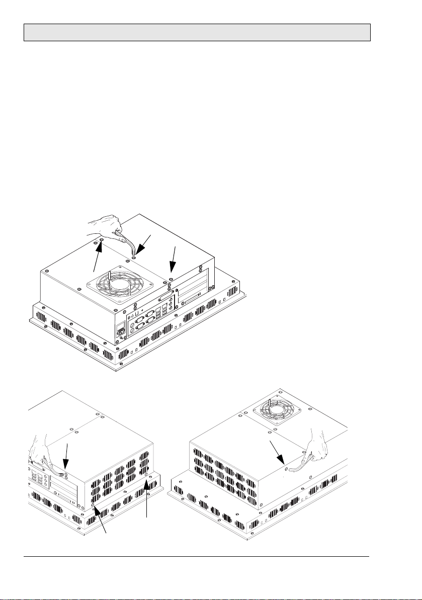
7.2 Changing the Fan Filter
The fan filter will have to be replaced regularly, especially in dusty environments.
Gently remove the fan cover, remove the filter and insert a new filter in its place.
7.3 PCI-board Installation
To install a PCI-board the right hand side part of the rear enclosure has to be
removed.
1. To open the enclosure remove the marked seven screws with an Allen key.
After removing the screws the enclosure can be easily removed.
32 Beijer Electronics, MAEN979B
Page 33
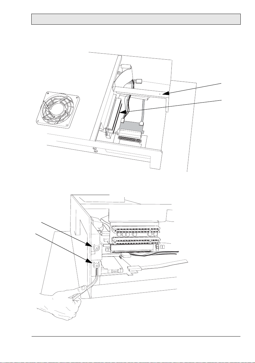
Service
The picture of the opened EPC below shows the board holder (1) and the 2 PCIslots (2).
1
2
2. Remove the cover of the desired slot to insert your PCI-board, by removing
the screw and pulling out the cover.
Beijer Electronics, MAEN979B 33
Page 34
Service
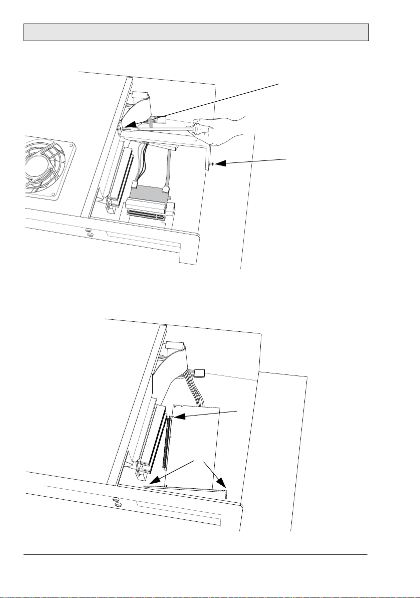
3
4
3. Remove the board holder by unscrewing the two marked screws.
4. Insert the PCI-board, if necessary bend the slot bracket a little bit. Please
ensure a correct fit at the rear edge (3) of the slot and make sure the metal
bracket goes into the groove (4).
34 Beijer Electronics, MAEN979B
Page 35
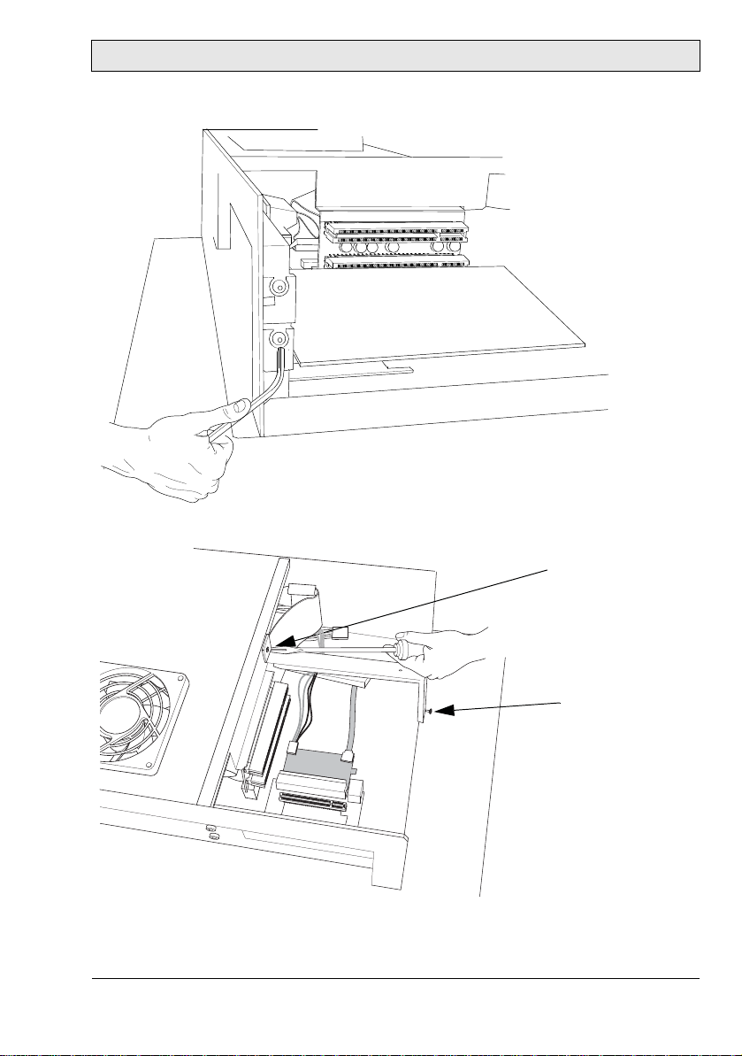
5. Mount your PCI-board and make sure to properly tighten the screw.
6. Re-assemble the board holder and tighten the two screws properly.
Service
Beijer Electronics, MAEN979B 35
Page 36

Service
5
7. To ensure an optimal use of the board holder, we recommend that you put
wide boards in the lower slot and narrow boards in the upper. This way the
support can be used in the correct way.
Note:
If two wide boards are used, the short support (5) can be removed.
7.4 Cable Fixing Points
When connecting interface cables such as RS232, USB, LAN or VGA, the cables must be fixed at the cable fixing points, to avoid that the cables loosen be-
cause of vibrations.
36 Beijer Electronics, MAEN979B
Page 37

Te ch ni ca l Da ta
8 Technical Data
The EPC T150/T170/T190 C2D Nautic models have touch screens; the EPC
150/170/190 C2D Nautic models have an antireflective glass.
Parameter
Size, W x H x D,
complete with front
plate
Mounting depth 145 mm (245 mm including clearance) 114 mm (214
Front panel seal IP65 Rear panel seal IP20 according to DIN EN 60529 IP20 according
Weight 9 kg 10 kg 13 kg 5.5 kg
Processor Intel Core 2 Duo
Cache / Bus Speed 4 MB / 800 MHz
System chipset Intel GME965 / ICH8-M
BIOS Award 4 MBit Flash memory, supports ACPI
RAM 2 GB DDR2-SDRAM (SODIMM), max. 4 GB
Graphics chip Intel GMA X3100
IDE controller 1 x IDE port, supports Ultra ATA 100/66/33
Serial ports 2 x RS232
Ethernet 2 x 10/100/1 000 Mb ps
USB ports 4 x USB 2.0 (rear side)
Extension s l o ts 2 x PCI up to 220 mm length
Compact Flash ports 1 x internal (optional) bootable
Keyboard/mouse 2 x PS/2
VGA For external monitor, supports QXGA 2048 x 1536
DVI For external monitor, supports DVI 1.0
Audio ports Line in/out, microphone in
EPC T150/150
C2D Nautic
412 x 351 x 142.5 mm430 x 390 x
1 x USB 2.0 (front side) under hatch
1 x external not bootable
EPC T170/170
C2D Nautic
142.5 mm
EPC T190/190
C2D Nautic
483.2 x 444 x
142.5 mm
EPC C2D Box
Nautic
389 x 276 x 114
mm
mm including
clearance)
to DIN EN
60529 on all
sides
4 x USB 2.0
Beijer Electronics, MAEN979B 37
Page 38

Technical Data
Parameter
Power consumption
at rated voltage
Fuse 1 AT (230 V AC) or 6.3 AT (24 V DC)
Power supply options 115-230 V AC ± 15%. 1 A max (switch on peak 30 A).
Active area of display
Pixels 1024 x 768 1280 x 1024 Pixel pitch (RGB) 0.297 x 0.297 mm0.264 x 0.264 mm0.294 x 0.294 mm-
Max. number of colors
View angle
(up/down/left/
right) (typical)
Light intensity (ty p ical)
Contrast ratio 450:1 1500:1 1000:1 Response time (r ise/
fall)
Display technology TN PVA SPVA Touch screen tech-
nology
Touch screen resolu-
tion
Ambient tempera-
ture
Relative ambie nt
humidity
Storage temperature -20 ° to +70 °C
Relative storage
humidity
Basic RBC software
version
* Only applies to EPC T150 C2D Nautic/ EPC T170 C2D Nautic/ EPC T190 C2D Nautic
EPC T150/150
C2D Nautic
85 VA
24 V DC ± 15%. 3 A max (switch on peak 15 A).
304.1 x 228.1 mm337.9 x 270.3 mm376.3 x 301.1 mm-
16.7 million -
50/60/75/75 ° 89/89/89/89 ° -
250 cd/m
6 ms/19 ms 15 ms/10 ms 13 ms/7 ms -
Resistive* -
4096 x 4096 points* -
-15 ° to +55 °C
30% to 90% non-condensed
10% to 90% non-condensed
V0003 May 28, 2009
Please contact Beijer Electronics/Elektronik-Systeme Lauer for
information about current version.
2
EPC T170/170
C2D Nautic
EPC T190/190
C2D Nautic
EPC C2D Box
Nautic
-
38 Beijer Electronics, MAEN979B
Page 39
Drawings
9 Drawings
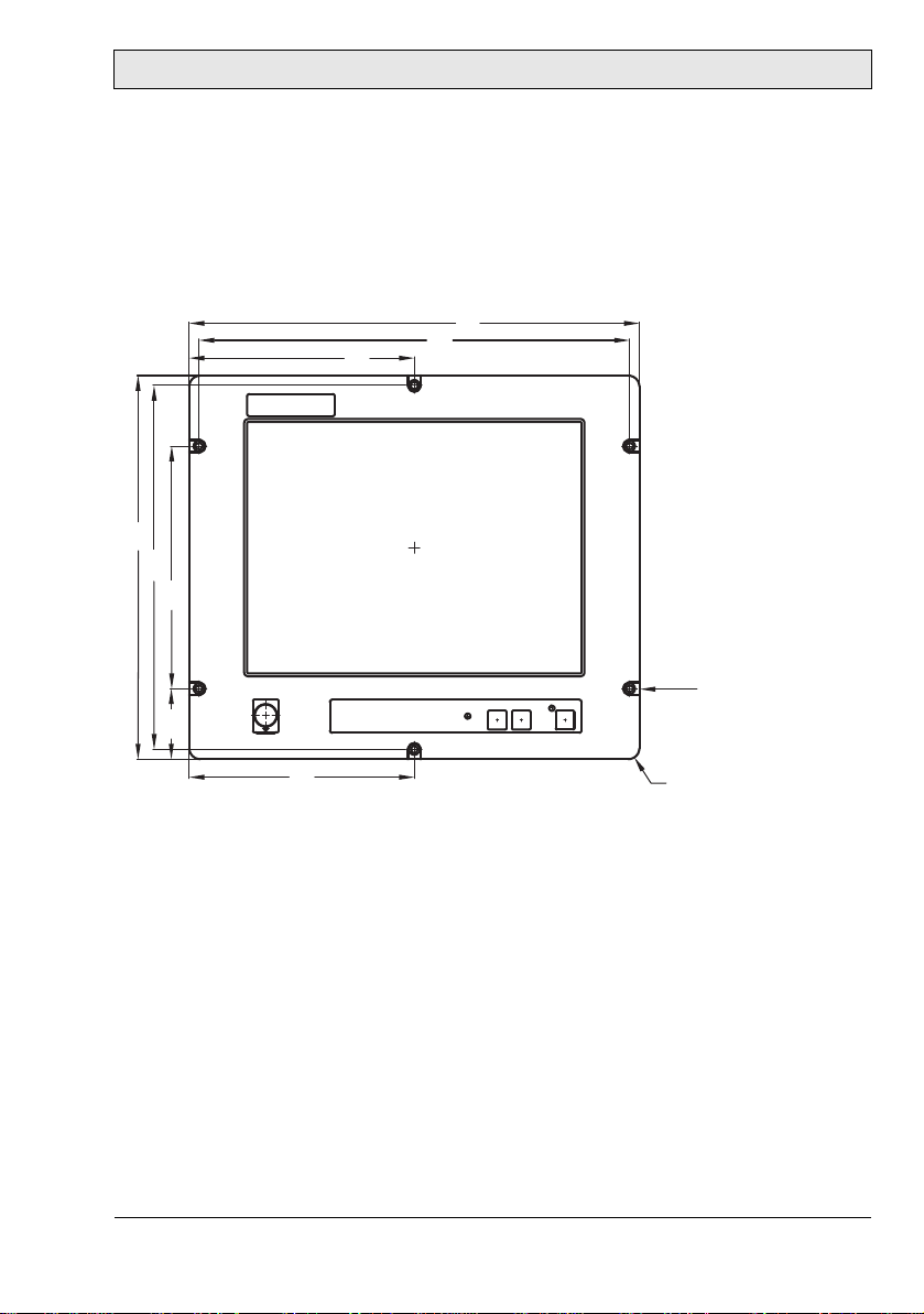
9.1 EPC T150/150 C2D Nautic Front View
412
206
351
333
394
6 x hole Ø 6.5 mm
64.5 222
206
Beijer Electronics, MAEN979B 39
R10
Page 40

Drawings
9.2 EPC T150/150 C2D Nautic Cut Out Drawing
Cut out dimensions: 369.0 x 324.0 mm, tolerance +1 mm. Space for mounting
screws on all sides: 15 mm = needed space 399.0 x 354.0 mm.
222
333
55.5
0
+1
324
+1
369
197
0
197
394
6 x bore holes Ø 6.5 mm
Front plate 412.0 x 351.0 mm, tolerance: ±0.2 mm.
Mounting method: 6 x M6x25 steel screws DIN 6912. Screws and o-ring seals
are included.
Max. 8 mm thick mounting frame.
40 Beijer Electronics, MAEN979B
Page 41
Drawings
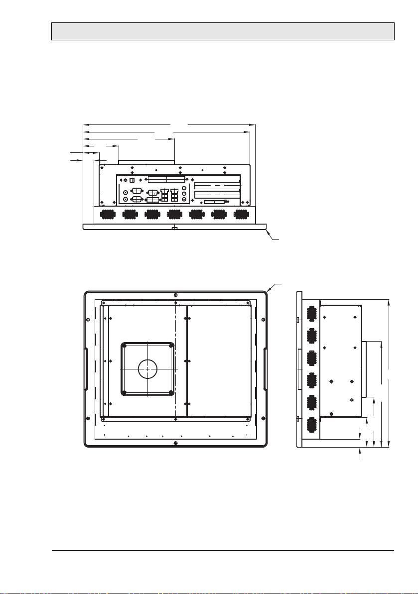
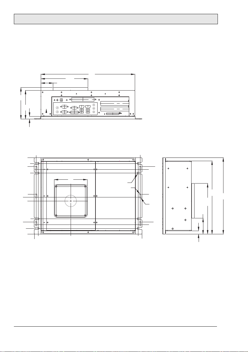
9.3 EPC T150/150 C2D Nautic Outline Drawings
Bottom view
387.5
375.5
36.5
24.5
80.3
Rear view Side view
205.7
R3
R10
112.8
67.5
18
Beijer Electronics, MAEN979B 41
333
238.2
Page 42
Drawings
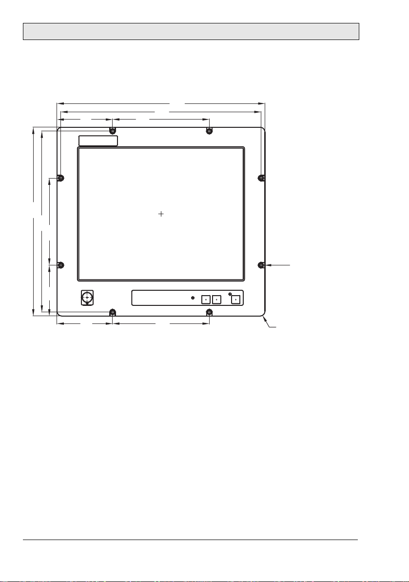
9.4 EPC T170/170 C2D Nautic Front View
430
414
115
390
374
180
105
200
8 x bore holes Ø 6.5 mm
115 200
R10
42 Beijer Electronics, MAEN979B
Page 43
Drawings
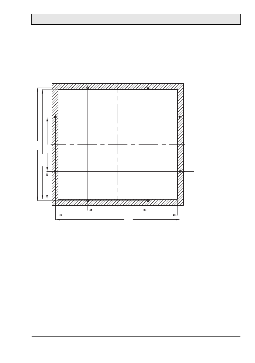
9.5 EPC T170/170 C2D Nautic Cut Out Drawing
Cut out dimensions: 396.0 x 364.0 mm, tolerance +1 mm. Space for mounting
screws on all sides: 15 mm = needed space 426.0 x 394.0 mm.
374
180
0
+1
364
8 x bore holes Ø 6.5 mm
92
200
+1
396
0
414
Front plate 430.0 x 390.0 mm, tolerance: ±0.2 mm.
Mounting method: 8 x M6x25 steel screws DIN 6912. Screws and o-ring seals
are included.
Max. 8 mm thick mounting frame.
Beijer Electronics, MAEN979B 43
Page 44

Drawings
9.6 EPC T170/170 C2D Nautic Outline Drawings
Bottom view
412
384.5
45.5
89.3
18
Rear view Side view
214.7
R3
R10
109.5
15
44 Beijer Electronics, MAEN979B
361.5
280.2
154.8
Page 45

Drawings
9.7 EPC T190/190 C2D Nautic Front View
444
426
235
104.4 104.6
126.6
126.6
230
230
483.2
126.6
8 x bore holes Ø 6.5 mm
R10
Beijer Electronics, MAEN979B 45
Page 46

Drawings
9.8 EPC T190/190 C2D Nautic Cut Out Drawing
Cut out dimensions: 438.0 x 416.0 mm, tolerance +1 mm. Space for mounting
screws on all sides = 15 mm - needed space 468.0 x 446.0 mm.
235
0
+1
416
426
8 x bore holes Ø 6.5 mm
90.4
230
+1
438
0
465.2
Front plate 483.2 x 444.0 mm, tolerance: ±0.2 mm.
Mounting method: 8 x M6x25 screws DIN 6912. Screws and o-ring seals are
included.
Max. 8 mm thick mounting frame.
46 Beijer Electronics, MAEN979B
Page 47

Drawings
9.9 EPC T190/190 C2D Nautic Outline Drawings
Bottom view
458.1
115.9
72.1
25.1
12
241.3
Rear view Side view
411.1
R3
R10
146.5
16.5
Beijer Electronics, MAEN979B 47
398.5
317.2
191.8
Page 48
Drawings
9.10 EPC Box C2D Nautic Outline Drawings
Bottom view
131.5
339
382
244244
234
Ø7
Ø4.6
144
Ø8.5
44
34
389
374.5
169.2
43.8
114
104
10
Rear view Side view
276
255.5
220.5
119
144
134
120
55.5
44
20.5
0
0
14.5
264
276
182.7
57.3
12
Mounting method: 6 x M4x12 steel screws DIN 912 or 4 x M6x12 steel screws
DIN 912. Screws are included.
48 Beijer Electronics, MAEN979B
Page 49

Head Office
Sweden
Beijer Electronics Products AB
Box 426
201 24 Malmö, SWEDEN
Tel: +46 40 35 86 00
Fax: +46 40 93 23 01
info@beijerelectronics.com
Subsidiaries
Germany
Elektronik-Systeme Lauer GmbH & Co. KG
Kelterstraße 59
72669 Unterensingen, GERMANY
Tel.: +49 70 22/96 60 0
Fax: +49 70 22/96 60-103
info@lauer-hmi.com
USA
Beijer Electronics Inc.
939 N. Plum Grove Road, Suite F
Schaumburg, IL 601 73, USA
Tel: +1 847 619 6068
Fax: +1 847 619 6674
info.usa@beijerelectronics.com
China
Beijer Electronics Co. Ltd
Room 201, Buildning B, No. 1618,
Yishan Road, Shanghai 201103, CHINA
Tel: +86 21 6145 0400
Fax: +86 21 6145 0499
info@beijerelectronics.cn
Taiw an
Beijer Electronics Corp.
7 & 8 F, No. 108 Minquan Rd.
Xindian City, Taipei County, TAIWAN
23141
Tel: +886-2-2218-3600
Fax: +886-2-2218-9547
info.tw@beijerelectronics.com
 Loading...