

Page 1

G-series GN-9212 DeviceNet Rev. 1.01.docx
DeviceNet network adapter
GN-9212
User manual
Page 1 of (54)
Page 2

GN-9212 User Manual
G-series GN-9212 DeviceNet Rev. 1.01.docx
REV
PAGE
REMARKS
DATE
EDITOR
DOCUMENT CHANGE SUMMARY
1.00 New Document
1.01 First release 2019/01/29 NJL
2018/7/30
Page 2 of (54)
Page 3

GN-9212 User Manual
G-series GN-9212 DeviceNet Rev. 1.01.docx
Contents
1.
Important Notes ......................................................................................................................... 5
1.1. Safety Instruction ................................................................................................................ 6
1.1.1.
Symbols ........................................................................................................................ 6
1.1.2.
Safety Notes .................................................................................................................. 6
1.1.3.
Certification ................................................................................................................... 6
2.
Specification .............................................................................................................................. 7
2.1. The Interface ........................................................................................................................ 7
2.2. General Specification ........................................................................................................... 8
2.3. Device Net Specification ...................................................................................................... 9
2.4. LED Indicator ..................................................................................................................... 10
2.4.1
Module Status LED (MOD).......................................................................................... 10
2.4.2
Network Status LED (NET) ......................................................................................... 10
2.4.3
Terminating Resistance Status LED (TER) ................................................................ 11
2.4.5
Field Power, System Power Status LED (Field Power, System Power LED)............ 11
3.
Dimension ................................................................................................................................ 12
3.1. GN-9212 ................................................................................................................................ 12
4.
Mechanical Set Up ................................................................................................................... 13
4.1. Total Expansion .................................................................................................................. 13
4.2. Plugging and Removal of the Components. ..................................................................... 13
5.
Configuration and Operation ................................................................................................... 14
5.1. G-Bus Specification ........................................................................................................... 14
5.1.1
G-Bus System ............................................................................................................. 14
5.2. DeviceNet Composition ..................................................................................................... 17
5.3.1.
DeviceNet Cable Specification ................................................................................... 18
5.3.2.
Communication Cable Specification ......................................................................... 18
5.3.3
DeviceNet Connector Specification ........................................................................... 20
5.3.4
Terminator Resistor Specification ............................................................................. 22
5.4. DeviceNet Module Configurations .................................................................................... 23
5.4.2 I/O Process Image Map ................................................................................................... 24
5.4.3. Object Models ................................................................................................................. 24
5.5. Object Setting ...................................................................................................................... 26
5.5.1.
Identity Object............................................................................................................. 26
5.5.2.
Message Router Object .............................................................................................. 27
5.5.3.
DeviceNet Object ........................................................................................................ 28
5.5.4.
Assembly Object ......................................................................................................... 30
5.5.5.
Connection Object ...................................................................................................... 31
Page 3 of (54)
Page 4

GN-9212 User Manual
G-series GN-9212 DeviceNet Rev. 1.01.docx
5.5.6.
Acknowledge Handler Object ..................................................................................... 36
5.5.7.
G-Bus Manager Object ............................................................................................... 37
5.5.8.
Expansion Slot Object ................................................................................................ 40
5.5.9.
I/O Format Setting ....................................................................................................... 41
6.
MODBUS INTERFACE .............................................................................................................. 42
6.1. MODBUS Interface Register/Bit Map ................................................................................ 42
6.2. Supported MODBUS Function Codes ............................................................................... 42
6.2.1.
8 (0x08) Diagnostics ................................................................................................... 45
6.2.2.
Error Response ........................................................................................................... 46
6.2.3.
MODBUS Special Register Map ................................................................................. 47
6.2.4.
Adapter Identification Special Register (0x1000, 4096) ............................................. 47
6.2.5.
Adapter Information Special Register (0x1100, 4352) ................................................ 47
6.2.6.
Expansion Slot Information Special Register (0x2000, 8192) ................................... 48
6.4.
Trouble Shooting ............................................................................................................... 51
Page 4 of (54)
Page 5

GN-9212 User Manual
G-series GN-9212 DeviceNet Rev. 1.01.docx
1.
Important Notes
Solid state equipment has operationalcharacteristics differing from those of electromechanical equipment.
Safety Guidelines for t he Application, Installation and Maintenance of Solid State Controls describes some
important differences between solid state equipment and hard-wired electromechanical devices.
Because of this difference, and also because of the wide variety of uses for solid state equipment, all
persons responsible for applying this equipment must satisfy themselves that each intendedapplication of
this equipment is acceptable.
In no event will CREVIS be responsible or liable for indirect or consequential damages resulting from the use
or application of this equipment.
The examples and diagrams in this manual are included solely for illustrative purposes. Because of the many
variables and requirementsassociated with any particular installation, CREVIS cannot assume responsibility
or liability for actual use based on the examples and diagrams.
Warning!
If you don't follow the directions, it could cause a personal injury, damage to the equipment or
explosion
Do not assemble the products and wire with power applied to the system. Else it may cause an electric
arc, which can result into unexpected and potentiallydangerous action by field devices. Arching is
explosion risk in hazardous locations. Be sure that the area is non-hazardous or remove system power
appropriatelybefore assembling or wiring the modules.
Do not touch any terminalblocks or IO modules when system is running. Else it may cause the unit
to
an electric shock or malfunction.
Keep away from the strange metallic materials not related to the unit and wiring works should
be controlled by the electric expert engineer. Else it may cause the unit to a fire, electric shock
or malfunction.
Caution!
If you disobey the instructions, there may be possibility of personal injury, damage to equipment
or explosion. Please follow below Instructions.
• Check the rated voltage and terminal array before wiring. Avoid the circumstances over 55℃ of
temperature. Avoid placing it directly in the sunlight.
• Avoid the place under circumstances over 85% of humidity.
• Do not place Modules near by the inflammablematerial. Else it may cause a fire.
• Do not permit any vibration approachingit directly.
• Go through module specification carefully, ensure inputs, output connections are made with the
specifications. Use standard cables for wiring.
• Use Product under pollution degree 2 environment.
Page 5 of (54)
Page 6

GN-9212 User Manual
G-series GN-9212 DeviceNet Rev. 1.01.docx
Identifies information about practices or circumstances that can cause an
explosion
death property damage or economic loss
Identifies information that is critical for successful application and understanding of
the product
Identifies information about practices or circumstances that can lead to personal
in
Attentions
consequences
1.1. Safety Instruction
1.1.1.
Symbols
in a hazardous environment, which may lead to personal injury or
jury, property damage, or economic loss.
help you to identitya hazard, avoid a hazard, and recognize the
1.1.2.
Safety Notes
The modulesare equipped with electronic componentsthat may be destroyed by
electrostatic discharge. When handling the modules, ensure that the environment
(persons, workplace and packing) is well grounded. Avoid touching conductive
components, e.g. G-BUS Pin.
1.1.3.
Certification
c-UL-us UL Listed Industrial Control Equipment, certified for U.S. and Canada
See UL File E235505
CE Certificate
EN 61000-6-2; Industrial Immunity
EN 61000-6-4; Industrial Emissions
Page 6 of (54)
Page 7

GN-9212 User Manual
G-series GN-9212 DeviceNet Rev. 1.01.docx
2.
Specification
2.1. The Interface
Page 7 of (54)
Page 8

GN-9212 User Manual
G-series GN-9212 DeviceNet Rev. 1.01.docx
General Specification
Supply voltage : 24Vdc nominal
Power Dissipation
70mA @ 24Vdc
Current for I/O Module
1.5A @ 5Vdc
System power to internal logic : Non-Isolation
Supply voltage : 24Vdc typical (Max. 32Vdc)
Max. Current Field Power Contact
DC 10A Max
Weight
154g
Module Size
54mm x 99mm x 70mm
Environment Condition
Refer to ‘1. Environment Specification’
Environmental Specification
60℃ ~ 70℃ : Power dissipation is limitedto 0.8A.
UL Temperature
-20℃~60℃
Storage Temperature
-40℃~85℃
Relative Humidity
5% ~ 90% non-condensing
Mounting
DIN rail
2.2. General Specification
System Power
Isolation
Field Power
Operating Temperature
Supply voltage range : 16~32Vdc
Protection : Output current limit (Min. 1.5A)
Reverse polarity protection
System power I/O driver : Isolation
* Field Power Range is defferent depending on IO Module series.
Refer to IO Module’s Specification.
-40℃ ~ 60℃ : 1.5A full load is allowed.
Page 8 of (54)
Page 9

GN-9212 User Manual
G-series GN-9212 DeviceNet Rev. 1.01.docx
Items
Specification
Communication Interface Specification
Adapter Type
Group 2 Only Slave
Max. Expansion Slot
63 Slots
I/O Data Size
Max 128 bytes each slot
Max. Length Bus Line
Max.100m@500Kbps, Max. 250m@250Kbps, Max. 500m@125Kbps
Max. Network Node
64 Nodes
125Kbps(Max. 500m)
500Kbps(Max. 100m)
Protocol
Poll, Bit-Strobe, Cyclic, COS
Node MAC ID Setup
DIP Switch
Terminating Resistance Setup
DIP Switch
Bus Connection
5 Pin Open-Style Connector
Other Serial Port
RS232 for MODBUS/RTU, Touch Panel or IOGuide
Node
:
1 (Fixed)
Stop bit
:
1 (Fixed)
6 Status LEDs
1 Green, Field Power Status
Module Location
Starter module left side of G-Series system
Field Power Detection
About 14Vdc
2.3. Device Net Specification
Baud Rate
Serial Configuration(RS232)
Indicator
250Kbps(Max. 250m)
Baud Rate : 115200 (Fixed)
Data bit
Parity bit : No parity (Fixed)
1 Green/Red, Module Status (MOD)
1 Green/Red, Network Status (NET)
1 Green, TerminatingResistance Status (TER)
1 Green/Red, Expansion I/O Module Statsus (IOS)
1 Green, System Power Status
:
8 (Fixed)
Page 9 of (54)
Page 10

GN-9212 User Manual
G-series GN-9212 DeviceNet Rev. 1.01.docx
Status
LED
To indicate
Not Powered
OFF
Power is not supplied to the unit.
Device Operational
Green
The unit is operating in normal condition.
Flashing
Green
EEPROM parameteris not initialized yet.
Serial Number is zero value (0x00000000)
Minor Fault
Flashing Red
Device has an recoverable Fault.
Unrecoverable Fault
Red
Device has an unrecoverable fault.
Status
LED
To indicate
Not Powered
Not On-line
Device is not on-line or may not be powered.
- Not completed Dup-MAC_ID test yet
Device is on-line but has no connections in the established
- Not allocated to a master
On-line,
Connected
Flashing
Red
Failed communication
- Bus-off
LED No.
LED Function / Description
LED Color
MOD
Module Status
Green/Red
NET
Network Status
Green/Red
TER
Termination Resistance Status
Green
IOS
Extension module Status
Green/Red
System Power
System Power Enable
Green
Field Power
Field Power Enable
Green
2.4. LED Indicator
2.4.1
Module Status LED (MOD)
Device in Standby
2.4.2
Network Status LED (NET)
On-line,
Not connected
Connection Time-out
Critical Communication
Failure
OFF
Flashing
Green
Green Device is on-line and allocated to a master.
Red
state.
- Passed Dup-MAC_ID test
One or more I/O connections are in the time-out state.
- Duplicate MAC ID
Page 10 of (54)
Page 11

GN-9212 User Manual
G-series GN-9212 DeviceNet Rev. 1.01.docx
Status
LED
To indicate
Not applied
OFF
Terminatingresistance is not applied.
Applied
On
Terminatingresistance is applied.
Status
LED
To indicate
Not Powered
No Expansion Module
G-Series Internal bus is normal but does not
(Passed the expansion module configuration)
G-Series Internal Bus Connection,
Run Exchanging I/O
One or more expansion module occurred in fault state.
expension module.
ing
Status
LED
To indicate
Not supplied field, system power
OFF
Not supplied 24Vdc field power, 5Vdc system power.
Suppliedfield, system power
Green
Supplied 24Vdc field power, 5Vdc system power.
2.4.3
Terminating Resistance Status LED (TER)
2.4.4
G-Series Internal Bus Status LED (IOS LED)
OFF Device has no expansion module or may not be powered.
G-Series Internal Bus On-line,
Do not Exchanging I/O
G-Series Internal Bus Connection
Fault during
Exchanging I/O
Expansion Configuration
Failed
2.4.5
Field Power, System Power Status LED (Field Power, System Power LED)
Flashing
Green
Green Exchanging I/O data.
Red
RedFlash
Red
exchanging I/O data.
- Changed expansion module configuration.
- Internal Bus communication failure.
- Mismatch vendor code between adapter and
Failed to initalize expansion module.
- Detect invalid expansion module ID.
- Overflow Input/Output size.
- Too many expansion module.
- Initial protocol failure.
Page 11 of (54)
Page 12

GN-9212 User Manual
G-series GN-9212 DeviceNet Rev. 1.01.docx
3.
Dimension
3.1. GN-9212
(mm)
Page 12 of (54)
Page 13
GN-9212 User Manual
G-series GN-9212 DeviceNet Rev. 1.01.docx
4.
Mechanical Set Up
4.1. Total Expansion
The number of the module assembly that can be connected is 63. So the maximum length is 798mm
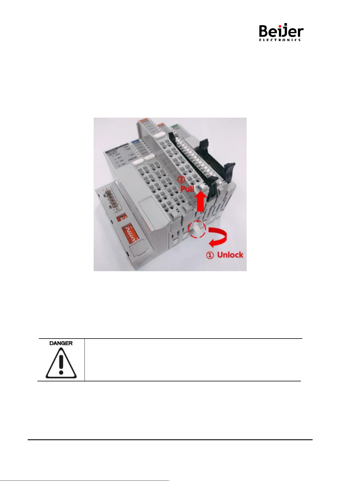
4.2. Plugging and Removal of the Components.
As above figure in order to safeguard the FnIO module from jamming, it should be fixed onto the DIN rail
with locking level. To do so, fold on the upper of the locking lever.
To pull out the FnIO module, unfold the locking lever as below figure.
Before work is done on the components, the voltage supply must be turned off.
Page 13 of (54)
Page 14
GN-9212 User Manual
G-series GN-9212 DeviceNet Rev. 1.01.docx
5.
Configuration and Operation
5.1. G-Bus Specification
5.1.1
G-Bus System
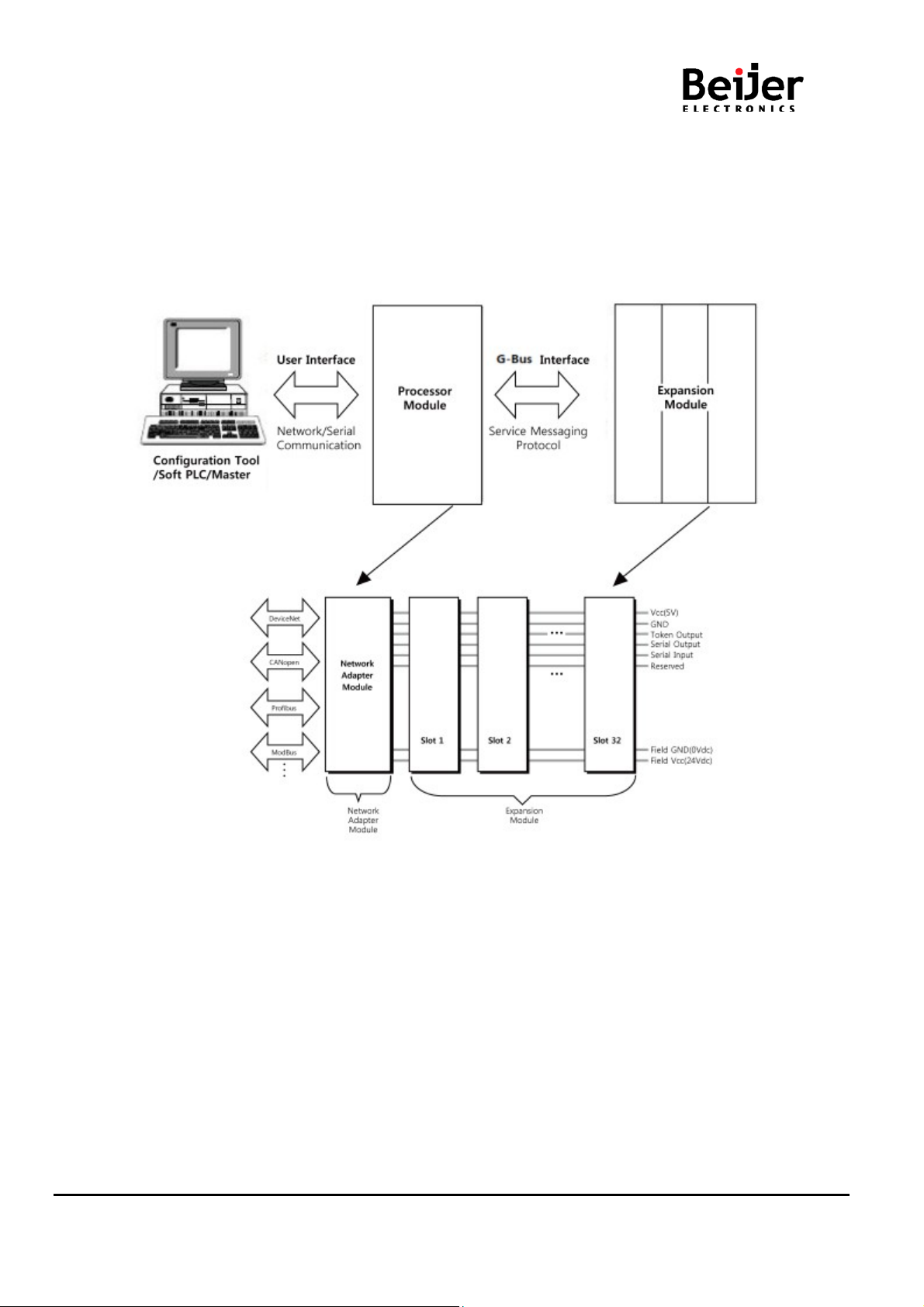
• Network Adapter Module
The Network Adapter Module forms the link between the field bus and the field devices with the Expansion
Modules.
The connection to different field bus systems can be established by each of the corresponding Network
Adapter Module, e.g. for SyncNet, PROFIBUS, CANopen, DeviceNet, Ethernet/IP, CC-Link,
MODBUS/Serial, MODBUS/TCP etc.
Page 14 of (54)
Page 15

GN-9212 User Manual
G-series GN-9212 DeviceNet Rev. 1.01.docx
•
Expansion Module
The Expansion Modules are supported a variety of input and output field devices. There
are digital and analog input/outputmodules and special function modules.
•
Two types of G-Bus Message
- Service Messaging
- I/O Messaging
Page 15 of (54)
Page 16

GN-9212 User Manual
G-series GN-9212 DeviceNet Rev. 1.01.docx
No.
Name
Description
1
Vcc
System supply voltage (5V dc).
2
GND
System Ground.
3
Token Output
Token output port of Processor module.
4
Serial Output
Transmitter output port of Processor module.
5
Serial Input
Receiver input port of Processor module.
6
Reserved
Reserved for bypass Token.
7
Field GND
Field Ground.
8
Field Vcc
Field supply voltage (24Vdc).
5.1.2
G-Bus Pin Description
Communicationbetween the NA series and the expansion module as well as system / field power supply of
the bus modules is carried out via the internal bus. It is comprised of 6 data pin and 2 field power pin.
Do not touch data and field power pins in order to avoid soiling and damage by ESD
noise.
Page 16 of (54)
Page 17

GN-9212 User Manual
G-series GN-9212 DeviceNet Rev. 1.01.docx
Name
Description
Node is Slave that is charged each address number. DeviceNet is comprised
in Slave. Slave contacts external I/O.
Trunk line is cable that is installed terminator resistor.
In the DeviceNet, both trunk and drop line is used.
Number of Connection mode for DeviceNet is 2 modes. First is T-branch and
Multi drop is method what trunk and drop line contacts with node directly.
Terminator resistor is that is installed for reduction a reflected wave in both
ends trunk line.
For using DeviceNet, user must supply communication power to each node
connector through the DeviceNet cable.
5.2. DeviceNet Composition
Network Composition
DeviceNet Network Installation
DeviceNet Network Set up is like following figure2.
Node
Trunk / Drop Line
Connection Mode
Terminator Resistor
Communication Power
of Master and Slave. Mas ter manages DeviceNet and organizes external I/O
Drop line is cable that branch from trunk line
Second is multi-drop.
T-branch is method that branches off drop-lineby T-branch tap
Page 17 of (54)
Page 18
GN-9212 User Manual
G-series GN-9212 DeviceNet Rev. 1.01.docx
Physical
Characteristics
Communication cable
#18 Copper(minimum): 19 strand
min(individuallytinned)
#24 Copper(minimum): 19 strand
min(individuallytinned)
Insulation diameter
0.150 inches
0.077 inches
Light blue
White
Light blue
White
Pair twist/ft
3(approx.)
5(approx.)
Impedance
120Ω ± 10% (at 1MHz)
Power pair
#15 Copper(minimum): 19 strand
Insulation diameter
0.098 inches
0.055 inches
Red
Black
Red
Black
1.0mil/1mil,Al/Mylar
(pull-on applied)
1.0mil/1mil,Al/Mylar
(pull-on applied)
#18 Copper(minimum): 19 strand
min
Roundness
Radius delta to be within 15% of 0.5 0.D
Agency certification
NEC(UL) type CL2(min.)
Jacket marker
Vender name & part#, and additional
5.3.
(DeviceNet Specification Volume Release2.0 Errate2, appendix B)
DeviceNet Module (GN-9212) Installations
5.3.1.
5.3.2.
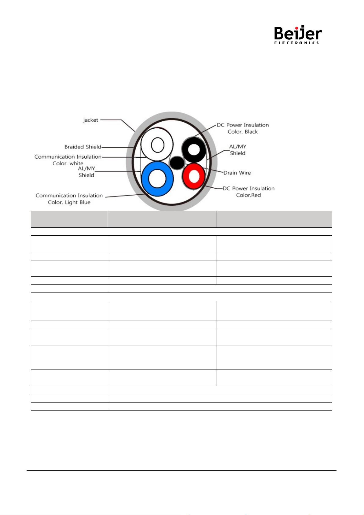
DeviceNet Cable Specification. In the DeviceNet Specification There is the exclusive cable bellows
DeviceNet Cable Specification
Communication Cable Specification
Thick Cable Spec Thin Cable Spec
Conductor pair size
Colors
Conductor pair size
Color
Tape shield over pair
Drain wire
min(individuallytinned)
Al side out w/shorting fold
The maximum length of network for each cable type is as follows.
#22 Copper(minimum): 19 strand
min(individuallytinned)
Al side out w/shorting fold
#22 Copper(minimum): 19 strand min
Page 18 of (54)
Page 19

GN-9212 User Manual
G-series GN-9212 DeviceNet Rev. 1.01.docx
Communication
rate
Truck Exchange
(Thick Cable)
125Kb
500m(1640ft)
1.0
156m(512ft)
6m(20ft)
250Kb
250m(820ft)
1.0
76m(256ft)
6m(20ft)
500Kb
100m(328ft)
1.0
38m(128ft)
6m(20ft)
Communication
rate
Truck Exchange
(Thick Cable)
125Kb
100m(328ft)
5.0
156m(512ft)
6m(20ft)
250Kb
100m(328ft)
2.5
76m(256ft)
6m(20ft)
500Kb
100m(328ft)
1.0
38m(128ft)
6m(20ft)
-Thick Cable
-Thin Cable
Truck Length
Truck Length
Cumulative drop Maximum drop
Cumulative drop Maximum drop
Page 19 of (54)
Page 20

GN-9212 User Manual
G-series GN-9212 DeviceNet Rev. 1.01.docx
Male General Characteristics
Specification
Number of Pins
5
Coupling Nut
Male
Coupling Nut Thread
7/8–166 UN-2A THD
Rotation
Optional
Pin out
Drain : Pin1, V+ : Pin2, V- : Pin3, CAN_H : Pin4, CAN_L : Pin5
Female General Characteristics
Specification
Number of Pins
5
Coupling Nut
Female
Coupling Nut Thread
7/8–166 UN-2B THD
Rotation
Required
Pin out
Drain : Pin1, V+ : Pin2, V- : Pin3, CAN_H : Pin4, CAN_L : Pin5
Physical Characteristics
Specification
30 micro inch gold minimum over 50 micro inch nickel minimum or
be 24 karat
5.3.3
DeviceNet Connector Specification
Wiping Contact Plating Requirements
5 micro inch gold minimum over 20 micro inch
Palladium-nickelminimum over 50 micro inch nickels. All gold must
Page 20 of (54)
Page 21

GN-9212 User Manual
G-series GN-9212 DeviceNet Rev. 1.01.docx
Male General Characteristics
Specification
Number of Pins
5
Coupling Nut
None
Coupling Nut Thread
None
Rotation
None
Pin out
V- : Pin1, CAN_L : Pin2, Shield : Pin3, CAN_H : Pin4, V+ : Pin5
Female General Characteristics
Specification
Number of Pins
5
Coupling Nut
None
Coupling Nut Thread
None
Rotation
None
Pin out
V- : Pin1, CAN_L : Pin2, Shield : Pin3, CAN_H : Pin4, V+ : Pin5
Physical Characteristics
Specification
30 micro inch gold minimum over 50 micro inch nickel minimum or
be 24 karat
Wiping Contract Life
1000 insertion - extractions
Electrical Characteristics
Specification
Operating Voltage
25 Volt minimum
Contact Rating
8 Amps minimum
5 micro inch gold minimum over 20 micro inch
Wiping Contact Plating Requirements
Palladium-nickelminimum over 50 micro inch nickels. All gold must
Device network power is 24V. Network and I/O field power must be separated
One power is provided per network
The use of an incorrect supply voltage or frequency can cause severe damage
to the component.
Page 21 of (54)
Page 22

GN-9212 User Manual
G-series GN-9212 DeviceNet Rev. 1.01.docx
Terminating Resistance Switch
#1
#2
Applied
On
On
Not applied
Off
Off
5.3.4
Terminator Resistor Specification
Page 22 of (54)
Page 23

GN-9212 User Manual
G-series GN-9212 DeviceNet Rev. 1.01.docx
MAC ID
1 2 3 4 5 6 BAUD RATE
7
8
0
Off
Off
Off
Off
Off
Off
125kbps
Off
Off
1
On
Off
Off
Off
Off
Off
250kbps
On
Off
~
500kbps
Off
On
63
On
On
On
On
On
On
AUTO
On
On
5.4. DeviceNet Module Configurations
5.4.1.
DeviceNet MAC ID Setup
Each DeviceNet Adapter must have a unique MAC ID (from 0 to 63) so that it can be addressed
independentlyfrom other nodes.
MAC ID addresses have to be unique throughout the entire interconnected
Networks.
Page 23 of (54)
Page 24

GN-9212 User Manual
G-series GN-9212 DeviceNet Rev. 1.01.docx
5.4.2 I/O Process Image Map
An expansion module may have 3 types of data as I/O data, configuration parameter and memory register.
The data exchange between network adapter and expansion modules is done via an I/O process image data
by G-Series Internal Bus protocol. The following figure shows the data flow of process image between
network adapter and expansion modules.
5.4.3. Object Models
A DeviceNet node is modeled as a collection of Objects. An Object provides an abstract representation of a
particular component within a product. The realization of this abstract object model within a product is
implementationdependent. In other words, a product internally maps this object model in a fashion specific
to its implementation.
The objects and their components are addressed by a uniform addressing scheme consisting of:
Media Access Control Identifier (MAC ID), an integer identification value assigned to each node on a
DeviceNet network.
Class Identifier (Class ID), an integer identification value assigned to each Object Class accessible from the
network.
Instance Identifier (Instance ID), an integer identificationvalue assigned to an Object Instance that identifies
it among all Instances of the same Class.
Attribute Identifier (Attribute ID), an integer identificationvalue assigned to a Class and/or Instance Attribute.
Service Code, an integer identificationvalue which denotes a particular Object Instance and/or Object Class
function.
Supported Objects
Page 24 of (54)
Page 25

GN-9212 User Manual
G-series GN-9212 DeviceNet Rev. 1.01.docx
Name of Object
Type
Number of Instances
Class Code
Identity
Required
1
01
HEX
Message Router
Required
1
02
HEX
DeviceNet
Required
1
03
HEX
Assembly
Required
2
04
Connection
Required
4
05
HEX
Acknowledge
Handler
G-Bus Manager
Vendor-specific
1
70
HEX
Expansion Slot
Vendor-specific
1~63
71
HEX
Object
Behavior
Interface
Identity
Device identification, reset service
Message Router
DeviceNet
Configures port attributes
Message Router
Defines I/O data format and concatenates
configuration data
I/O Connection or Message Router
Contains the number of logical ports into
or out-of the device
Message Router
Acknowledge
Handler
Manage the reception of message
acknowledgments
Message Router
G-Series Internal
Bus Manager
Management functions for the G-Series
Internal Bus
Message Router
Management functions for the expansion
Message Router
- Device Type Number: 0C
Objects Behavior, Interface
Assembly
Connection
(Communications Adapter)
HEX
Required 1 2B
HEX
HEX
Expansion Slot
slot
Page 25 of (54)
Page 26
GN-9212 User Manual
G-series GN-9212 DeviceNet Rev. 1.01.docx
Service Code
Implemented for
Service Name
Value
Class
Instance
0x05
No
Yes
Reset
0: Reset Only
1: Reset and Factory Default
0x0E
No
Yes
Get_Attribute_Single
Instance
Attribute
Access
1
Get
Vendor ID
1 word
0x02E5 (741), Crevis. Co., Ltd.
2
Get
Device Type
1 word
0x000C (Network Adapter)
3
Get
Product Code
1 word
0x9020 (GN-9212)
Get
Revision
Structure of:
5
Get
Status
1 word
Defined in Spec (0x0005) *
6
Get
Serial Number
2 word
Unique Number
Get
Product Name
Structure of:
1A (26)
9
Get
Check Sum
1 word
EEPROM Checksum Code
Get
I/O Main State
1 word
0x01: Init State
Vendor-specific
102(66h)
Get
Firmware Code
1 byte
0x71
103(67h)
Get
ODVA
UINT
0x0A17 → “2002. 10. 22.”
5.5. Object Setting
5.5.1.
Class Code: 01
Identity Object
Common Services
Class Attributes
None
Instance Attributes
ID
1
ID
4
HEX
Rule
Name Data Size Value
- Major
- Minor
1 byte
1 byte
1 ~ 9
01 ~ 255
7
100(64h)
- String Length
- ASCII String
Conformance
Test Revision
1 byte
STRING
“GN-9212_DeviceNet,G-Series”
0x02: Idle State
0x03: Run State
0x04: Stop State
0x05: Fault State
0x06: Reset State
0x07: CRC error State
Page 26 of (54)
Page 27

GN-9212 User Manual
G-series GN-9212 DeviceNet Rev. 1.01.docx
104(68h)
Get
Firmware Release
UDINT
0xYYYYMMDD
107(6Bh)
Get
Inspection Date
UDINT
0xYYYYMMDD
Class Code: 02
HEX
Date
* Spec. = The CIP Networks library, ODVA
5.5.2.
Common Services
None
Class Attributes
None
Instance Attributes
None
Message Router Object
ex) 0x20160817 → 2016/08/17
Page 27 of (54)
Page 28

GN-9212 User Manual
G-series GN-9212 DeviceNet Rev. 1.01.docx
Implemented for
Class
Instance
0x0E
Yes
Yes
Get_Attribute_Single
0x10
No
Yes
Set_Attribute_Single
0x4B
No
Yes
Allocate_Master/Slave_Connection_Set
0x4C
No
Yes
Release_Master/Slave_Connection_Set
Instance
Attribute
Access
Data
0 1 Get
Revision
1 word
02, 00
Instance
Attribute
Access
Data
1
Get/Set*
MAC ID
1 byte
0 ~ 63
2
Get
Baud Rate**
1 byte
0=125K, 1=250K, 2=500K, 3=Auto
Get/Set
Bus off Interrupt
BOOL
faulted node recovery,
Get
Bus-Off Counter
USINT
0 ~ 255
Get
Allocation
Structure
- Allocation Choice
Get
MACID
Switch
USINT
0 ~ 99
Get
Baud Rate Switch
USINT
0 : 125kbps
Class Code: 03
HEX
5.5.3.
DeviceNet Object
Common Services
Service
Code
Class Attributes
ID
ID
Instance Attributes
ID
ID
Rule
Rule
Name
Name
Service Name
Size
Size
Value
Value
1
(0x01 : Enable)
4
3
Information
- Allocation Choice
5
- Master's MAC ID
of:
BYTE
USINT
Defined in Spec.
- Master’s MAC ID
255: unallocated
0~63: Master MAC ID
8
9
Value
Value
Actual value of Switch
1 : 250kbps
2 : 500kbps
3 : Auto
Page 28 of (54)
Page 29

GN-9212 User Manual
G-series GN-9212 DeviceNet Rev. 1.01.docx
Vendor-specific
100(64h)
Get
Auto-Baud Action**
BOOL
0: Enabled (default)
101(65h)
Get/Set
Quick Start
BOOL
0 : Normal Start-up (default)
(Not allowed to set the Baud Rate
from Network)
1: Disabled
(Allowed to set the Baud Rate from
Network)
1 : Quick Start-up***
*The MAC ID Switch value = 0~63: Not allowed to set the MAC ID from Network.
Behavior: Changed new MAC ID → Device will be restarted.
**Refer to 2.4.3 (DeviceNet MAC ID & Buad Rate Setup)
***Baudrate only 500kbps.
Page 29 of (54)
Page 30

GN-9212 User Manual
G-series GN-9212 DeviceNet Rev. 1.01.docx
Implemented for
Class
Instance
0x0E
No
Yes
Get_Attribute_Single
0x10
No
Yes
Set_Attribute_Single
Instance
Attribute
Access
Input (Produced)
Array n
Input process current image
Output (Consumed)
Array n
Output process current image
5.5.4.
Class Code: 04
Assembly Object
HEX
Common Services
Service Code
Class Attributes
None
Input Instance Attributes
Input/outputInstance ID
ID
100(64h) 3 Get
150(96h) 3 Set/Get
ID
Rule
Service Name
Name Data Type Value
Process Image Data
Process Image Data
BYTE
BYTE
data
data
Page 30 of (54)
Page 31
GN-9212 User Manual
G-series GN-9212 DeviceNet Rev. 1.01.docx
Implemented for
Class
Instance
0x0E
No
Yes
Get_Attribute_Single
0x10
No
No
Set_Attribute_Single
Instance
Attribute
Access
Get
state
USINT
Defined in Spec
2
Get
instance_type
USINT
0: Explicit Message
3
Get
transportClass_trigger
BYTE
83
Get
produced_connection_id
UINT
*0x040B : MAC ID=01,
Get
consumed_connection_id
UINT
*0x040C : MAC ID=01,
6
Get
initial_comm_characteristics
BYTE
21
7
Get
produced_connection_size
UINT
0x0206 (=518)
8
Get
consumed_connection_size
UINT
0x0206 (=518)
Get/Set
expacted_packet_rate
UINT
2504 (default)
12
Get/Set
watchdog_timeout_action
USINT
3 : Deferred Delete (default)
Get
produced_connection_path_
UINT
00, 00
14
Get
produced_connection_path
Array of USINT
Empty
Get
consumed_connection_path
UINT
00, 00
16
Get
consumed_connection_path
Array of USINT
Empty
Class Code: 05
HEX
5.5.5.
Connection Object
Common Services
Service Code
Class Attributes
None
Instance Attributes for Explicit Messaging Connection
ID
ID
Rule
Name Data Type Value
1
Service Name
* 0x03 : The connection has
been validly/fully configured
and the configuration has been
successfully applied.
HEX
4
Message group 2, Message ID
3
1
5
Message ID 4
HEX
9
Timer Resolution of 8msec
13
length
15
_ length
attribute 3 transport Class trigger = 0x83 → Direction=Server,
Production Trigger=IGNORED,Transport Class = 3.
This is the value assigned to this attribute within the server end-point of an Explicit Messaging Connection
Page 31 of (54)
Page 32

GN-9212 User Manual
G-series GN-9212 DeviceNet Rev. 1.01.docx
Instance
Attribute
Access
Data
1
Get
State
USINT
Defined in Spec
2
Get
instance_type
USINT
1: I/O Message
3
Get
transportClass_trigger
BYTE
82
4 Get
produced_connection_id
UINT
* 0x03C1 : MAC ID=01,
Get
consumed_connection_id
UINT
* 0x040D : MAC ID=01,
6
Get
initial_comm_characteristics
BYTE
01
Get
produced_connection_size
UINT
Followed by IO process
Get
consumed_connection_size
UINT
Followed by IO process
Get/Set
expacted_packet_rate
UINT
Timer Resolution of 8msec
12
Get
watchdog_timeout_action
USINT
0: Time Out (default)
Get
produced_connection_path_
UINT
0 or 6
Get
produced_connection_path
Array of
Get
consumed_connection_path
UINT
0 or 6
Get
consumed_connection_path
Array of
Instance
Attribute
Access
1
Get
state
USINT
Defined in Spec
2
Get
instance_type
USINT
1: I/O Message
Instance Attributes for Poll I/O Connection
ID
2
ID
5
7
8
9
Rule
Name
Type
Value
HEX
Message ID=6,
Unconnected Explicit
Request Message
Message ID=5, Group 2
message Identifier
HEX
image
image
* 200(decimal)
13
length
14
USINT
15
16
_
length
USINT
Instance Attributes for Bit-Strobe I/O Connection
ID
ID
Rule
Name Data Type Value
3
3 Get transportClass_trigger BYTE 82
HEX
Page 32 of (54)
Page 33

GN-9212 User Manual
G-series GN-9212 DeviceNet Rev. 1.01.docx
Get
produced_connection_id
UINT
*0x0381 : MAC
Get
consumed_connection_id
UINT
*0X0400 : MAC ID =
6
Get
initial_comm_characteristics
BYTE
02
7
Get
produced_connection_size
UINT
0x08
8
Get
consumed_connection_size
UINT
0x08
Get/Set
expacted_packet_rate
UINT
Timer Resolution of
12
Get
watchdog_timeout_action
USINT
0: Time Out (default)
Get
produced_connection_path_
UINT
0 or 6
Get
produced_connection_path
Array
of
Get
consumed_connection_path
UINT
0 or 6
Get
consumed_connection_path
Array
of
Instance
Attribute
Access
Data
1
Get
State
USINT
Defined in Spec
2
Get
instance_type
USINT
1: I/O Message
3
Get
transportClass_trigger
BYTE
12
4
Get
produced_connection_id
UINT
5
Get
consumed_connection_id
UINT
6
Get
initial_comm_characteristics
BYTE
1
Get
produced_connection_size
UINT
Followed by
IO
Process
Get
consumed_connection_size
UINT
Followed by
IO
Process
9
Get/Set
expected_packet_rate
UINT
Timer Resolution of 8msec
4
5
9
13
14
15
length
_
length
USINT
ID=01, Message
ID=14,
group 1
00, Message ID = 0,
Message group 2
8msec
* 200
Message
HEX
16
Instance Attributes for COS I/O Connection (Acknowledged)
ID
4
ID
Rule
7
8
Name
USINT
Type
Value
HEX
image
image
Page 33 of (54)
Page 34

GN-9212 User Manual
G-series GN-9212 DeviceNet Rev. 1.01.docx
12
Get/Set
watchdog_timeout_action
USINT
0: Time Out (default)
Get
produced_connection_path_
UINT
0 or 6
Get
consumed_connection_path
UINT
4
Get
consumed_connection_path
Array of
20 2B 24 01
17
Get/Set
production_inhibit_time
UINT
00, 00
Instance
Attribute
Access
Data
Get
State
USINT
Defined in Spec
2
Get
instance_type
USINT
1: I/O Message
3
Get
transportClass_trigger
BYTE
10
Get
produced_connection_id
UINT
* 0x0341 MAC ID : 01,
5
Get
consumed_connection_id
UINT
0FFFF
6
Get
initial_comm_characteristics
BYTE
0F
Get
produced_connection_size
UINT
Followed by
IO
Process
Get
consumed_connection_size
UINT
Followed by
IO
Process
9
Get/Set
expacted_packet_rate
UINT
Timer Resolution of 8msec
12
Get/Set
watchdog_timeout_action
USINT
0: Time Out (default)
Get
produced_connection_path_
UINT
0 or 6
Get
produced_connection_path
Array of
13
14
15
Get produced_connection_path Array of
length
_
length
16
Instance Attributes for COS I/O Connection (Unacknowledged)
ID
ID
Rule
Name
1
4
4
USINT
USINT
Type
Value
* 0x01 : Configuring
HEX
Message ID=13, Message
Group 1
HEX
HEX
7
8
image
image
13
14
length
USINT
Page 34 of (54)
Page 35

GN-9212 User Manual
G-series GN-9212 DeviceNet Rev. 1.01.docx
Get
consumed_connection_path
UINT
0
Get
consumed_connection_path
Array of
Empty
17
Get/Set
production_inhibit_time
UINT
00, 00
15
16
_
length
USINT
Page 35 of (54)
Page 36

GN-9212 User Manual
G-series GN-9212 DeviceNet Rev. 1.01.docx
Instance
Attribute
Access
1
Set
Acknowledge Timer
UNIT
Default: 10
2
Get
Retry Limit
USINT
1
Get
COS
Producing
UINT
4
Class Code: 2B
HEX
Implemented for
Class
Instance
0x0E
Yes
Yes
Get_Attribute_Single
5.5.6.
Acknowledge Handler Object
Common Services
Service
Code
Class Attributes
None
Instance Attributes
ID
ID
1
3
Service Name
Rule
Name Data Type Value
Connection Instance
Page 36 of (54)
Page 37

GN-9212 User Manual
G-series GN-9212 DeviceNet Rev. 1.01.docx
Service Code
Implemented for
Service Name
Class
Instance
0x0E
No
Yes
Get_Attribute_Single
0x10
No
Yes
Set_Attribute_Single
Instan
Attribute
Acces
1
Get
Number of Slot
USINT
(include deactivated slot)
Get
External IDs
Array of
See Table 5.1.
Get
G-Series Internal Bus
USINT
0x03 : Run state
11
Get
Input (Produced) Byte Size
UINT
IO input byte size
Get
Output
(Consumed) Byte
UINT
IO output byte size
Get
Run-time fault code
DWORD
#0 : G-bus error count
Get
Firmware Revision
USINT
#0 : Major revision
Byte
Description
0
Network Adapter Module External ID = 0x9212
1
External ID for slot position #1
2
External ID for slot position #2
...
...
62
External ID for slot position #62
63
External ID for slot position #63
Class Code: 70
HEX (112D)
5.5.7.
G-Bus Manager Object
Common Services
Class Attributes
None
Instance Attributes
ce ID
ID
10
4
s Rule
Name Data Type Value
128 BYTE
Status
0x04 : Stop state
0x05 : Fault state
0x07 : CRC state
1
12
Size
#1 : G-bus error code (Table
113
5.2.)
#2 : Error slot number
#3 : NA status
150
#1 : Minor revision
Table 5.1. External IDs (=Expansion Module ID)
Page 37 of (54)
Page 38

GN-9212 User Manual
G-series GN-9212 DeviceNet Rev. 1.01.docx
Byte
Description
0x02
Connection Fault
0x03
Configuration Fault
0x04
No Expansion module
0x05
Invalid attribute value
0x06
Too much data
0x07
Vendor Error
0x08
Not expected slot
0x09
CRC error
Table 5.2.G-bus error code
0x00 Normal Operation
Page 38 of (54)
Page 39

GN-9212 User Manual
G-series GN-9212 DeviceNet Rev. 1.01.docx
Service Code
Implemented for
Service Name
Class
Instance
0x0E
No
Yes
Get_Attribute_Single
0x10
No
Yes
Set_Attribute_Single
Instance
Attribute
Access
Get
Module External ID
USINT
IO Name = External ID (2Byte)
Get
Input Offset Table
Structure
Byte offset
in
the
Input
Get
Output Offset Table
Structure
Byte offset
in
the
Output
Get
Input Data
Array of
Read Input data size defined by
Get/Set
Output Data
Array of
Read/Write Output data size
Get
Configuration
USINT
Refer to
Configuration
Get/Set
R/W Configuration
n Byte
Data array size defined by
100
Get
Product Code
4 Byte
Class Code: 71
HEX (113D)
5.5.8.
Expansion Slot Object
Common Services
Class Attributes
None
Instance Attributes
ID
ID
1~63
(Slot
Address)
1
3
Rule
Name Data Type Value
- Byte Offset
- Bit Offset
of:
USINT
USINT
ex) IO Name : GT-1238
= External ID : 0x1238
Assembly
Corresponding bit offset in the
byte
(If Input data length is zero, then
return Empty.)
- Byte Offset
4
- Bit Offset
of:
USINT
USINT
Assembly
Corresponding bit offset in the
byte
(If Output data length is zero,
then return Empty.)
5
6
8
9
Parameter
length
Data
Data
BYTE
BYTE
attributes 2.
If Input data length is zero, then
return Empty.
defined by attributes 2.
If Output data length is zero,
then return Empty.
Parameter document
attributes 8.
Page 40 of (54)
Page 40

GN-9212 User Manual
G-series GN-9212 DeviceNet Rev. 1.01.docx
Get
Firmware Revision
Structure
Expansion
Module
Firmware
102
*After the system is reset, the new “Set Value” action is applied. If
changed slot location, set default value automatically.
5.5.9.
DeviceNet I/O Data Format Setting
I/O Data Format of GN-9212 can be changed by DeviceNet Configuration Software
format is set by change G-BUS Manager Object value in Configuration Software.
BUS Manager Object for detail values
I/O Format Setting
of:
USINT
USINT
Revision
Data
Refer G-
Page 41 of (54)
Page 41

GN-9212 User Manual
G-series GN-9212 DeviceNet Rev. 1.01.docx
Start Address
Read/Write
Description
Func. Code
0x0000 ~
Read
Process input image registers (Real Input Register)
3,4,23
Process output image registers (Real Output
Register)
0x1000 *
Read
Adapter Identificationspecial registers.
3,4,23
0x1020 *
Read/Write
Adapter Watchdog, other time special register.
3,4,6,16,23
0x1100 *
Read/Write
Adapter Information special registers.
3,4,6,16,23
0x2000 *
Read/Write
Expansion Slot Information special registers.
3,4,6,16,23
Function
Code
This function code is used to read from 1 to 2000 contiguous
Status is indicated as 1= ON and 0= OFF.
This function code is used to read from 1 to 2000 contiguousstatus of
Status is indicated as 1= ON; 0= OFF.
3(0x03)
Read Holding
This function code is used to read the contents of a contiguousblock of
Start Address
Read/Write
Description
Func. Code
Process input image bits
Size of input image bit is size of input image register * 16.
Process output image bits
Size of output image bit is size of output image register * 16.
6.
MODBUS INTERFACE
6.1. MODBUS Interface Register/Bit Map
Register Map
0x0800 ~ Read/Write
* The special register map must be accessed by read/write of every each address (one address).
Register Map
0x0000~
0x1000~
Read
Read/Write
All input registers area are addressable by bit address.
All output registers area are addressable by bit address.
6.2. Supported MODBUS Function Codes
Function Description
3,16,23
2
1,5,15
status of coils in a remote device. The Request PDU specifies the
1(0x01)
2(0x02)
Read Coils
(Read output bit)
Read Discrete Inputs
(Read input bit)
starting address, i.e. the address of the first coil specified, and the
number of coils. In the PDU Coils are addressed starting at zero.
Therefore coils numbered 1-16 are addressed as 0-15. The coils in the
response message are packed as one coil per bit of the data field.
discrete inputs in a remote device. The Request PDU specifies the
starting address, i.e. the address of the first input specified, and the
number of inputs. In the PDU Discrete Inputs are addressed starting at
zero. Therefore Discrete inputs numbered 1-16 are addressed as 0-15.
The discrete inputs in the response message are packed as one input
per bit of the data field.
Page 42 of (54)
Page 42

GN-9212 User Manual
G-series GN-9212 DeviceNet Rev. 1.01.docx
Registers
holdingregisters in a remote device. The Request PDU specifies the
order bits.
This function code is used to read from 1 to approx. 125 contiguous
order bits.
This function code is used to write a single output to either ON or OFF
are illegaland will not affect the output.
This function code is used to write a single holding register in a remote
have been written.
MODBUS function code 08 provides a series of tests for checking the
data field of a normal response.
This function code is used to force each coil in a sequence of coils to
returns the function code, starting address, and quantity of coils forced.
This function code is used to write a block of contiguousregisters (1 to
quantity of registers written.
Read/Write Multiple
/Write a number of
Read a number of input words /Write a number of output words
starting address and number of holdingregisters to be read as well as
4(0x04)
5(0x05)
6(0x06)
8(0x08)
(Read output word)
Read Input Registers
(Read input word)
Write Single Coil
(Write one bit output)
Write Single Register
(Write one word
output)
Diagnostics
(Read diagnostic
register)
*Refer to the 4.2.1
starting register address and the number of registers. The register data
in the response message are packed as two bytes per register, with the
binary contents right justified within each byte. For each register, the
first byte contains the high order bits and the second contains the low
input registers in a remote device. The Request PDU specifies the
starting register address and the number of registers. The register data
in the response message are packed as two bytes per register, with the
binary contents right justified within each byte. For each register, the
first byte contains the high order bits and the second contains the low
in a remote device. The requested ON/OFF state is specified by a
constant in the request data field. A value of FF 00 hex requests the
output to be ON. A value of 00 00 requests it to be OFF. All other values
device. Therefore register numbered 1 is addressed as 0. The normal
response is an echo of the request, returned after the register contents
communication system between a client ( Master) device and a server (
Slave), or for checking various internal error conditionswithin a server.
The function uses a two–byte sub-function code field in the query to
define the type of test to be performed. The server echoes both the
function code and sub-function code in a normal response. Some of the
diagnostics cause data to be returned from the remote device in the
Write Multiple Coils
15(0x0F)
16(0x10)
23(0x17)
(Write a number of
output bits)
Write Multiple registers
(Write a number of
output words)
registers
(Read a number of
input words
either ON or OFF in a remote device. The Request PDU specifies the
coil references to be forced. Coils are addressed starting at zero. A
logical '1' in a bit position of the field requests the corresponding output
to be ON. A logical '0' requests it to be OFF. The normal response
approx. 120 registers) in a remote device.
The requested written values are specified in the request data field.
Data is packed as two bytes per register.
The normal response returns the function code, starting address, and
This function code performs a combination of one read operation and
one write operation in a single MODBUS transaction. The write
operation is performedbefore the read. The request specifies the
Page 43 of (54)
Page 43

GN-9212 User Manual
G-series GN-9212 DeviceNet Rev. 1.01.docx
output words)
the starting address, number of holdingregisters, and the data to be
in the read data field.
written. The byte count specifies the number of bytes to follow in the
write data field.
The normal response contains the data from the group of registers that
were read. The byte count field specifies the quantity of bytes to follow
- Refer to MODBUS APPLICATION PROTOCOL SPECIFICATION V1.1a
Page 44 of (54)
Page 44

GN-9212 User Manual
G-series GN-9212 DeviceNet Rev. 1.01.docx
Subfunction
Data Field
(Response)
0x0001(1)
0x0000, 0xFF00
Echo Request Data
Reset Only
Subfunction
Data Field
(Response)
0x000B(11)
0x0000
Total Message Count
Subfunction
Data Field
(Response)
0x000C(12)
0x0000
CRC Error Count
Subfunction
Data Field
(Response)
0x000D(13)
0x0000
Exception Error Count
Subfunction
Data Field
(Response)
0x000E(14)
0x0000
Slave Message Count
Subfunction
Data Field
(Response)
0x0000(0)
Any
Echo Request Data
6.2.1.
8 (0x08) Diagnostics
Sub-function 0x0000(0) Return Query Data
The data passed in the request data field is to be returned (looped back) in the response.
The entire response message should be identical to the request.
Data Field (Request)
Description
Sub-function 0x0001(1) Restart Communications Option
The remote device could be initialized and restarted, and all of its communications event counters are
cleared.
Especially, data field 0x55AA make the remote device to restart with factory default setup of EEPROM.
Data Field (Request)
Sub-function 0x000B(11) Return Bus Message Count
The response data field returns the quantity of messages that the remote device has detected on the
communications system since its last restart, clear counters operation, or power–up.
Data Field (Request)
Description
Description
Sub-function 0x000C(12) Return Bus Communication Error Count
The response data field returns the quantity of CRC errors encountered by the remote device since its last
restart, clear counters operation, or power–up.
Data Field (Request)
Sub-function 0x000D(13) Return Bus Exception Error Count
The response data field returns the quantity of MODBUS exception responses returned by the remote device
since its last restart, clear counters operation, or power–up.
Exception responses are described and listed in section 3.2.11.
Data Field (Request)
Sub-function 0x000E(14) Return Slave Message Count
The response data field returns the quantity of messages addressed to the remote device, or broadcast, that
the remote device has processed since its last restart, clear counters operation, or power–up.
Data Field (Request)
Sub-function 0x000F(15) Return Slave No Response Count
The response data field returns the quantity of messages addressed to the remote device for which it has
Description
Description
Description
Page 45 of (54)
Page 45

GN-9212 User Manual
G-series GN-9212 DeviceNet Rev. 1.01.docx
Subfunction
Data
(Response
Field
)
Slave
Count
No
Response
Subfunction
Data
(Response)
Field
ModBus,
Status
Internal
Same
1word
as
status
Exception
Code
The function code received in the query is not an allowable
action for the server (or slave).
Illegal Data
Address
The data address received in the query is not an allowable
address for the server (or slave).
Illegal Data
Value
A value contained in the query data field is not an allowable
value for server (or slave).
Slave Device
Failure
An unrecoverable error occurred while the server (or slave)
was attempting to perform the requested action.
do so.
Specialized use in conjunction with programming
free.
The server (or slave) attempted to read record file, but
server (or slave) device.
processing the request.
returned no response (neither a normal response nor an exception response), since its last restart, clear
counters operation, or power–up.
Data Field (Request)
0x000F(15) 0x0000
Sub-function 0x0064(100) Return Slave ModBus, Internal Status
The response data field returns the status of ModBus and Internal addressed to the remote device.
This status values are identical with status 1word of input process image.
Data Field (Request)
0x0064(100) 0x0000
6.2.2.
In an exception response, the server sets the MSB of the function code to 1. This makes the function code
value in an exception response exactly 80 hexadecimal higher than the value would be for a normal
response.
01 Illegal Function
02
Error Response
Exception Codes
Name Description
Description
Description
03
04
The server (or slave) has accepted the request and is
05
06
08
0A
Acknowledge
Slave Device
Busy
Memory Parity
Error
Gateway Path
Unavailable
processing it, but a long duration of time will be required to
commands.
The server (or slave) is engaged in processing a long–
duration program command. The client (or master) should
retransmit the message later when the server (or slave) is
detected a parity error in the memory. The client (or master)
can retry the request, but service may be required on the
Specialized use in conjunction with gateways, indicates that
the gateway was unable to allocate an internal
communication path from the input port to the output port for
Page 46 of (54)
Page 46

GN-9212 User Manual
G-series GN-9212 DeviceNet Rev. 1.01.docx
Address
Access
Type, Size
Description
0x1000(4096)
Read
1word
Vendor ID = 0x02E5(741), Crevis. Co., Ltd.
0x1001(4097)
Read
1word
Device type = 0x000C, Network Adapter
0x1002(4098)
Read
1word
Product code = 0x9020(GN-9212)
0x1003(4099)
Read
1word
Firmware revision, if 0x0101, revision 1.01
0x1004(4100)
Read
2word
Product unique serial number
String
34byte
Product name string (ASCII)
0x1006(4102)
Read
1word
Sum check of EEPROM
0x1010(4112)
Read
2word
Firmware release date
0x1013(4115)
Read
1word
Firmware Code = 0x9212
7word
- 2word
Composite Id of following address
0x1004(4100), Product serial number
Address
Access
Type, Size
Description
0x1102(4354)
Read
1word
Start address of input image word register. =0x0000
0x1103(4355)
Read
1word
Start address of output image word register. =0x0800
0x1104(4356)
Read
1word
Size of input image word register.
0x1105(4357)
Read
1word
Size of output image word register.
0x1106(4358)
Read
1word
Start address of input image bit. = 0x0000
0x1107(4359)
Read
1word
Start address of output image bit. =0x1000
0x1108(4360)
Read
1word
Size of input image bit.
0x1109(4361)
Read
1word
Size of output image bit.
0x110A(4362)
Read
1word
Update time for cyclic data change (same as 0x1028)
0x110C(4364)
Read
1word
Field power status
6.2.3.
The special register map can be accessed by function code 3, 4, 6 and 16. Also the special register map
must be accessed by read/write of every each address (one address).
MODBUS Special Register Map
6.2.4.
0x1005(4101) Read
0x101E(4126)
Adapter Identification Special Register (0x1000, 4096)
upto
Read
- 1word
- 1word
- 1word
- 1word
- 1word
"GN-9212_DeviceNet,G-Series"
0x1100(4352), Modbus RS232 Node. (Fixed 0x0001)
0x1000(4096), Vendor ID
0x1001(4097), Device type
0x1002(4098), Product code
0x1003(4099), Firmware revision
- String Type consist of valid string length (first 1word) and array of characters
6.2.5.
0x110D(4365) Read 1word Current Dip Switch State and Field Power Status (MSB)
Adapter Information Special Register (0x1100, 4352)
Page 47 of (54)
Page 47

GN-9212 User Manual
G-series GN-9212 DeviceNet Rev. 1.01.docx
ex) Dip SW(0x01), Field Power On = 0x8001
Expansion slot’s GT-number including GN
First 1word is adapter’s number, if GN-9289, then 0x9289
0x1110(4368)
Read
1word
Number of expansion slot
Expansion slot Module Id. Refer to Appendix A.1 Product
First 1word is adapter’s module id.
Hi byte is ModBus status, low byte is internal status.
Zero value means ‘no error’.
Adapter G-Series Revision. If 0x013C, G-Series Revision is
1.60
Slot#3
0x2040(8256)~0x205F(8287)
Slot#4
0x2060(8288)~0x207F(8319)
Slot#5
0x2080(8320)~0x209F(8351)
Slot#6
0x20A0(8352)~0x20BF(8383)
Slot#7
0x20C0(8384)~0x20DF(8415)
Slot#8
0x20E0(8416)~0x20FF(8447)
Slot#13
Slot#15
0x2180(8576)~0x219F(8607)
0x21C0(8640)~0x21DF(8671)
Slot#14
Slot#16
0x21A0(8608)~0x21BF(8639)
0x21E0(8672)~0x21FF(8703)
Slot#17
Slot#21
0x2200(8704)~0x221F(8735)
0x2280(8832)~0x229F(8863)
Slot#18
Slot#22
0x2220(8736)~0x223F(8767)
0x22A0(8864)~0x22BF(8895)
Slot#23
Slot#25
0x22C0(8896)~0x22DF(8927)
0x2300(8960)~0x231F(8991)
Slot#24
Slot#26
0x22E0(8928)~0x22FF(8959)
0x2320(8992)~0x233F(9023)
Slot#27
Slot#31
0x2340(9024)~0x235F(9055)
0x23C0(9152)~0x23DF(9183)
Slot#28
Slot#32
0x2360(9056)~0x237F(9087)
0x23E0(9184)~0x23FF(9215)
Slot#33
…..
0x2400(9216)~0x241F(9247)
Slot#34
0x2420(9248)~0x243F(9279)
Address
Offset
Expansion
Slot#1
Expansion
Slot#2
Expansion
Slot#3
Expansion
Slot#4
…
Expansion
Slot#63
+ 0x00(+0)
0x2000(8192)
0x2020(8224)
0x2040(8256)
0x2060(8288)
…
0x27C0(10176)
+ 0x01(+1)
0x2001(8193)
0x2021(8225)
0x2041(8257)
0x2061(8289)
…
0x27C1(10177)
+ 0x02(+2)
0x2002(8194)
0x2022(8226)
0x2042(8258)
0x2062(8290)
…
0x27C2(10178)
+ 0x03(+3)
0x2003(8195)
0x2023(8227)
0x2043(8259)
0x2063(8291)
…
0x27C3(10179)
+ 0x04(+4)
0x2004(8196)
0x2024(8228)
0x2044(8260)
0x2064(8292)
…
0x27C4(10180)
+ 0x05(+5)
0x2005(8197)
0x2025(8229)
0x2045(8261)
0x2065(8293)
…
0x27C5(10181)
+ 0x06(+6)
0x2006(8198)
0x2026(8230)
0x2046(8262)
0x2066(8294)
…
0x27C6(10182)
+ 0x07(+7)
0x2007(8199)
0x2027(8231)
0x2047(8263)
0x2067(8295)
…
0x27C7(10183)
+ 0x08(+8)
0x2008(8200)
0x2028(8232)
0x2048(8264)
0x2068(8296)
…
0x27C8(10184)
0x110E(4366) Read upto 33word
0x1113(4371) Read
0x1119(4377) Read 1word
0x111D(4381) Read 1word
*After the system is reset, the new “Set Value” action is applied.
** If the slot location is changed, set default value automatically (all expansion slot are live).
upto 33word
List.
6.2.6.
Slot#1
Slot#9
Slot#11
Slot#19
Expansion Slot Information Special Register (0x2000, 8192)
Each expansion slot has 0x20(32) address offset and same informationstructure.
0x2000(8192)~0x201F(8223)
0x2100(8448)~0x211F(8479)
0x2140(8512)~0x215F(8543)
0x2240(8768)~0x225F(8799)
Slot#2
Slot#10
Slot#12
Slot#20
0x2020(8224)~0x203F(8255)
0x2120(8480)~0x213F(8511)
0x2160(8544)~0x217F(8575)
0x2260(8800)~0x227F(8831)
Slot#29
Slot#63 0x27C0(10176)~0x27DF(10207)
0x2380(9088)~0x239F(9119)
Slot#30
0x23A0(9120)~0x23BF(9151)
Page 48 of (54)
Page 48

GN-9212 User Manual
G-series GN-9212 DeviceNet Rev. 1.01.docx
+ 0x09(+9)
0x2009(8201)
0x2029(8233)
0x2049(8265)
0x2069(8297)
…
0x27C9(10185)
+ 0x0A(+10)
0x200A(8202)
0x202A(8234)
0x204A(8266)
0x206A(8298)
…
0x27CA(10186)
+ 0x0B(+11)
0x200B(8203)
0x202B(8235)
0x204B(8267)
0x206B(8299)
…
0x27CB(10187)
+ 0x0C(+12)
0x200C(8204)
0x202C(8236)
0x204C(8268)
0x206C(8300)
…
0x27CC(10188)
+ 0x0D(+13)
0x200D(8205)
0x202D(8237)
0x204D(8269)
0x206D(8301)
…
0x27CD(10189)
+ 0x0E(+14)
0x200E(8206)
0x202E(8238)
0x204E(8270)
0x206E(8302)
…
0x27CE(10190)
+ 0x0F(+15)
0x200F(8207)
0x202F(8239)
0x204F(8271)
0x206F(8303)
…
0x27CF(10191)
+ 0x10(+16)
0x2010(8208)
0x2030(8240)
0x2050(8272)
0x2070(8304)
…
0x27D0(10192)
+ 0x11(+17)
0x2011(8209)
0x2031(8241)
0x2051(8273)
0x2071(8305)
…
0x27D1(10193)
+ 0x12(+18)
0x2012(8210)
0x2032(8242)
0x2052(8274)
0x2072(8306)
…
0x27D2(10194)
+ 0x13(+19)
0x2013(8211)
0x2033(8243)
0x2053(8275)
0x2073(8307)
…
0x27D3(10195)
+ 0x14(+20)
0x2014(8212)
0x2034(8244)
0x2054(8276)
0x2074(8308)
…
0x27D4(10196)
+ 0x15(+21)
0x2015(8213)
0x2035(8245)
0x2055(8277)
0x2075(8309)
…
0x27D5(10197)
+ 0x16(+22)
0x2016(8214)
0x2036(8246)
0x2056(8278)
0x2076(8310)
…
0x27D6(10198)
+ 0x17(+23)
0x2017(8215)
0x2037(8247)
0x2057(8279)
0x2077(8311)
…
0x27D7(10199)
+ 0x18(+24)
0x2018(8216)
0x2038(8248)
0x2058(8280)
0x2078(8312)
…
0x27D8(10200)
+ 0x19(+25)
0x2018(8217)
0x2038(8249)
0x2058(8281)
0x2078(8313)
…
0x27D9(10201)
+ 0x1A(+26)
0x201A(8218)
0x203A(8250)
0x205A(8282)
0x207A(8314)
…
0x27DA(10202)
+ 0x1B(+27)
0x201B(8219)
0x203B(8251)
0x205B(8283)
0x207B(8315)
…
0x27DB(10203)
+ 0x1C(+28)
0x201C(8220)
0x203C(8252)
0x205C(8284)
0x207C(8316)
…
0x27DC(10204)
+ 0x1D(+29)
0x201D(8221)
0x203D(8253)
0x205D(8285)
0x207D(8317)
…
0x27DD(10205)
+ 0x1E(+30)
0x201E(8222)
0x203E(8254)
0x205E(8286)
0x207E(8318)
…
0x27DE(10206)
+ 0x1F(+31)
0x201F(8223)
0x203F(8255)
0x205F(8287)
0x207F(8319)
…
0x27DF(10207)
Address
Offset
Type,
Size
+ 0x02(+2) **
Read
1word
Input start register address of input image word this slot.
+ 0x03(+3) **
Read
1word
Input word’s bit offset of input image word this slot.
+ 0x04(+4) **
Read
1word
Output start register address of output image word this slot.
+ 0x05(+5) **
Read
1word
Output word’s bit offset of output image word this slot.
+ 0x06(+6) **
Read
1word
Input bit start address of input image bit this slot.
+ 0x07(+7) **
Read
1word
Output bit start address of output image bit this slot.
+ 0x08(+8) **
Read
1word
Size of input bit this slot
+ 0x09(+9) **
Read
1word
Size of output bit this slot
+ 0x0A(+10)**
Read
n word
Read input data this slot
+ 0x0B(+11)**
Read/Write
n word
Read/write output data this slot
+ 0x0E(+14)
Read
1word
GT-number, if GT-1238, returns 0x1238
+ 0x0F(+15)
Read
String
First 1word is length of valid character string.
Access
Description
Page 49 of (54)
Page 49

GN-9212 User Manual
G-series GN-9212 DeviceNet Rev. 1.01.docx
upto
If GT-1238, returns
“GT-1238, 8DI, 24Vdc, Universal”
+ 0x10(+16)
Read
1word
Size of configuration parameter byte
Read/write Configuration parameter data, up to 8byte. Refer to
A.2 ***
Firmware Revision
ex) 0x00010010 (Major revision 1 /Minor revision 1, Rev 1.001)
+ 0x19(+25)
Read
2word
Firmware release date.
72byte
“00 1E 52 54 2D 31 32 33 38 2C 20 38 44 49 2C 20 32 34 56 64
63 2C 20 55 6E 69 76 65 72 73 61 6C 00 00”
Valid character size = 0x001E =30 characters,
+ 0x11(+17)** Read/Write n word
+ 0x17(+23) Read 2word
* After the system is reset, the new “Set Value” action is applied.
** Nothing of output, input, memory or configuration parametercorresponding slot returns Exception 02
Page 50 of (54)
Page 50

GN-9212 User Manual
G-series GN-9212 DeviceNet Rev. 1.01.docx
LED Status
Cause
Action
All LED turns off
- No power
- Check main power Cable
firmware
module for repair.
Master
and communication cable.
- Failure of exchanging data with
master
- Check status in software for
Master configuration.
- Check duplication address.
IOS LED turns off
- Device may not be powered.
- Check main power Cable
- Add one or more expansion
modules.
adapter and expansion module.
module for repair.
module for repair.
6.4.
Trouble Shooting
How to diagnose by LED indicator
MOD LED is red
NET LED turns off
NET LED flashed green
NET LED is red
IOS LED flashes red - Adapter has no expansion module
IOS LED is red
- Occurrence critical error in
- Failure of communication with
- Communication connecting lost
One or more expansion module
occurred in fault state.
- Detected invalid expansion module
ID.
- Overflowed Input/Output Size
- Too many expansion module
- Initializationfailure
- Communication failure.
- Changed expansion module
configuration.
- Mismatch vendor code between
- Contact Sales team and send
- Check main power for master
- Check BUS line cable for
connection with master.
- Use expansion slot up to 63.
- Compose that IO total size is not
excess.
- Check status of expansion IO
connection.
- Check the vendor code of
module.
- Check main power Cable
Field Power LED turns off - Field power is not supplied.
System Power LED turns
off
- System power is not supplied.
- Contact Sales team and send
- Check main power Cable
- Contact Sales team and send
Page 51 of (54)
Page 51
GN-9212 User Manual
G-series GN-9212 DeviceNet Rev. 1.01.docx
No.
GT-Number
Description
ID(hex)
Digital Input Module
1
GT-1238
8 Points, Universal, 24Vdc, 10RTB
1238
2
GT-123F
16 Points, Universal, 24Vdc, 20P connector
123F
3
GT-12DF
16 Points, Universal, 24Vdc, 18RTB
12DF
4
GT-12FA
32 Points, Universal, 24Vdc, 40P connector
12FA
5
GT-1804
4 Points, 120Vac, 10RTB
1804
6
GT-1904
4 Points, 240Vac, 10RTB
1904
Digital Output Module
7
GT-2318
8 Points, Sink, 24Vdc/0.5A, 10RTB
2318
8
GT-2328
8 Points, Source, 24Vdc/0.5A, 10RTB
2328
9
GT-221F
16 Points, Sink, 24Vdc/0.3A, 20P connector
221F
10
GT-222F
16 Points, Source, 24Vdc/0.3A, 20P connector
222F
11
GT-225F
16 Points, Sink, 24Vdc/0.3A, 18RTB
225F
12
GT-226F
16 Points, Source, 24Vdc/0.3A, 18RTB
226F
13
GT-22BA
32 Points, Sink, 24Vdc/0.3A, 40P connector
22BA
14
GT-22CA
32 Points, Source, 24Vdc/0.3A, 40P connector
22CA
15
GT-2618
8 Points, Sink, 24Vdc/2A, 10RTB
2618
16
GT-2628
8 Points, Source, 24Vdc/2A, 10RTB
2628
17
GT-2734
4 Points, MOS Relay, 240Vdc/ac, 0.5A, 10RTB
2734
18
GT-2744
4 Points, Relay, 24Vdc/2A, 240Vac/2A, 10RTB
2744
19
GT-2764
4 Points, MOS Relay, 24Vdc/ac, 2A, 10RTB
2764
20
GT-2784
4 Points, MOS Relay, 110Vdc/ac, 1A, 10RTB
2784
Analog Input Module
21
GT-3001
LoadCell (TBD)
3001
22
GT-3114
4 Channels, 0~20, 4~20mA, 12bits, 10RTB
3114
23
GT-3154
4 Channels, 0~20, 4~20mA, 16bits, 10RTB
3154
24
GT-3118
8 Channels, 0~20, 4~20mA, 12bits, 10RTB
3118
25
GT-3158
8 Channels, 0~20, 4~20mA, 16bits, 10RTB
3158
26
GT-311F
16 Channels, 0~20, 4~20mA, 12bits, 20P connector
311F
27
GT-315F
16 Channels, 0~20, 4~20mA, 16bits, 20P connector
315F
28
GT-317F
16 Channels, 0~20, 4~20mA, 12bits, 18RTB
317F
29
GT-319F
16 Channels, 0~20, 4~20mA, 16bits, 18RTB
319F
30
GT-3424
4 Channels, 0~10, 0~5, 1~5Vdc, 12bits, 10RTB
3424
31
GT-3464
4 Channels, 0~10, 0~5, 1~5Vdc, 16bits, 10RTB
3464
32
GT-3428
8 Channels, 0~10, 0~5, 1~5Vdc, 12bits, 10RTB
3428
33
GT-3468
8 Channels, 0~10, 0~5, 1~5Vdc, 16bits, 10RTB
3468
34
GT-342F
16 Channels, 0~10, 0~5, 1~5Vdc, 12bits, 20P connector
342F
35
GT-346F
16 Channels, 0~10, 0~5, 1~5Vdc, 16bits, 20P connector
346F
APPENDIX A
A.1 Product List
Page 52 of (54)
Page 52

GN-9212 User Manual
G-series GN-9212 DeviceNet Rev. 1.01.docx
36
GT-347F
16 Channels, 0~10, 0~5, 1~5Vdc, 12bits, 18RTB
347F
37
GT-349F
16 Channels, 0~10, 0~5, 1~5Vdc, 16bits, 18RTB
349F
38
GT-3704
4 Channels, RTD, 10RTB
3704
39
GT-3708
8 Channels, RTD, 20P connector
3708
40
GT-3804
4 Channels, Thermocouple, 10RTB
3804
41
GT-3808
8 Channels, Thermocouple, 20P connector
3808
42
GT-3901
AC Measurement
3901
43
GT-3914
4 Channels, Differential, 0~20, 4~20, +/-20mA, 12Bits, 10RTB
3914
44
GT-3934
4 Channels, Differential, 0~20, 4~20, +/-20mA, 16Bits, 10RTB
3934
45
GT-3918
8 Channels, Differential, 0~20, 4~20, +/-20mA, 12Bits, 18RTB
3918
46
GT-3938
8 Channels, Differential, 0~20, 4~20, +/-20mA, 16Bits, 18RTB
3938
47
GT-3924
4 Channels, Differential, 0~5, 0~10, +/-5, +/-10Vdc, 12Bits, 10RTB
3924
48
GT-3944
4 Channels, Differential, 0~5, 0~10, +/-5, +/-10Vdc, 16Bits, 10RTB
3944
49
GT-3928
8 Channels, Differential, 0~5, 0~10, +/-5, +/-10Vdc, 12Bits, 18RTB
3928
50
GT-3948
8 Channels, Differential, 0~5, 0~10, +/-5, +/-10Vdc, 16Bits, 18RTB
3948
Analog Output Module
51
GT-4114
4CH, 0~20mA, 12Bits, 10RTB
4114
52
GT-4154
4CH, 0~20mA, 16Bits, 10RTB
4154
53
GT-4118
8CH, 0~20mA, 12Bits, 10RTB
4118
54
GT-4158
8CH, 0~20mA, 16Bits, 10RTB
4158
55
GT-4424
4CH, 0~10Vdc, 12Bits, 10RTB
4424
56
GT-4464
4CH, 0~10Vdc, 16Bits, 10RTB
4464
57
GT-4428
8CH, 0~10Vdc, 12Bits, 10RTB
4428
58
GT-4468
8CH, 0~10Vdc, 16Bits, 10RTB
4468
59
GT-417F
16CH, 0~20mA, 12Bits, 18RTB
417F
60
GT-419F
16CH, 0~20mA, 16Bits, 18RTB
419F
61
GT-442F
16CH, 0~10Vdc, 12Bits, 20P Connector
442F
62
GT-446F
6CH, 0~10Vdc, 16Bits, 20P Connector
446F
63
GT-447F
16CH, 0~10Vdc, 12Bits, 18RTB
447F
64
GT-449F
16CH, 0~10Vdc, 16Bits, 18RTB
449F
Special Module
65
GT-5102
2CH, Encoder, Input, 5Vdc, 10RTB
5102
66
GT-5211
1CH, RS 232, RTS/CTS, Full Duplex Type, 10RTB
5211
67
GT-5212
2CH, RS 232, Full Duplex Type, 10RTB
5212
68
GT-5221
1CH, RS 485, Full Duplex Type, 10RTB
5221
69
GT-5231
1CH, RS 485, Half Full Duplex Type, 10RTB
5231
70
GT-5232
2CH, RS 485, Half Full Duplex Type, 10RTB
5232
71
GT-5352
2CH, Synchronous Serial Interface Input, 10RTB
5352
72
GT-5521
1CH, Stepper Module (TBD)
5521
Power Module
73
GT-7408
Shield Module
7408
74
GT-7508
Common for 0Vdc
7508
75
GT-7511
Power Expansion, In 24Vdc, Out 1A/5Vdc
7511
76
GT-7518
Common for 24Vdc
7518
77
GT-7588
Common for 0Vdc, 24Vdc
7588
78
GT-7641
Field Power, 5/24/48 Vdc, 110/220 Vac
7641
Page 53 of (54)
Page 53

GN-9212 User Manual
G-series GN-9212 DeviceNet Rev. 1.01.docx
A.2.
Glossary
-
System Power : The power for starting up CPU.
-
Field Power : The power for input and output line.
-
Terminator Resistor : Resistor for prevention reflected wave.
-
EDS : Electronic Data Sheet.
-
Sink : The method of in/output power supply if a device has no power source.
-
Source : The method of in/output power supply if a device has the power source.
Page 54 of (54)
Page 54

GN-9212 User Manual
G-series GN-9212 DeviceNet Rev. 1.01.docx
Head office
Beijer Electronics AB
Box 426
20124 Malmö, Sweden
Phone +46 40 358600
www.beijerelectronics.com
-
Page 55 of (54)
 Loading...