

Page 1
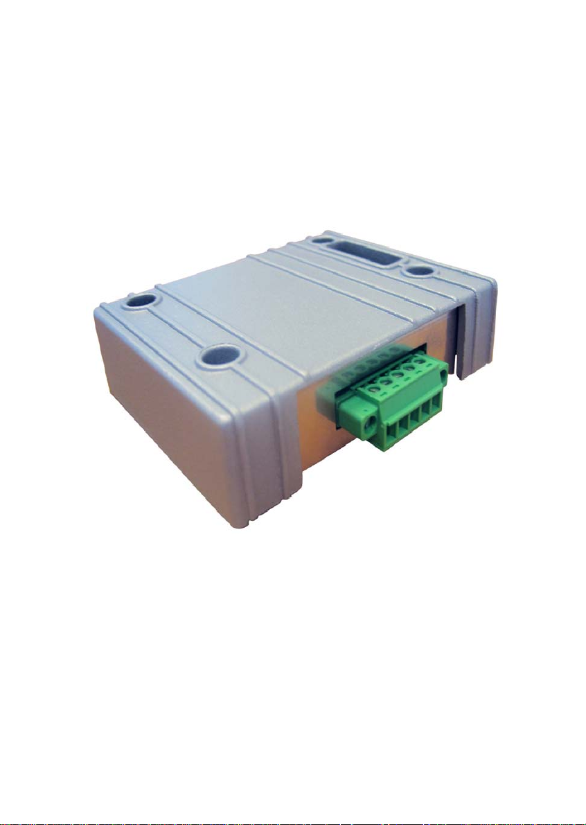
Expansion Module for CAN J1939
Installation
MAEN962 2009 -02
English
Page 2
Installation of Expansion Module for CAN J1939
The expansion module is used for the operator panel to communicate via CAN
J1939. The correct driver must be installed in the operator panel.
Important
Read the entire installation instructions prior to installing and using this equipment. Only qualified personnel may install, operate or repair this equipment.
Users must acquire the appropriate knowledge to use the equipment properly.
The manufacturer does not assume any responsibility for modified, altered or
renovated equipment.
THE MANUFACTURER SHALL NOT BE LIABLE TO ANYONE FOR
ANY DIRECT, INDIRECT, SPECIAL, INCIDENTAL, OR CONSEQUENTAL DAMAGES RESULTING FROM THE INSTALLATION, USE OR REPAIR OF THIS EQUIPMENT, WHETHER ARISING IN TORT,
CONTRACT, OR OTHERWISE. BUYER’S SOLE REMEDY SHALL BE
THE REPAIR, REPLACEMENT, OR REFUND OF PURCHASE PRICE,
AND THE CHOICE OF THE APPLICABLE REMEDY SHALL BE AT
THE SOLE DISCRETION OF THE MANUFACTURER.
Attention:
Observe pr ecautions for handling electrostatic sen sitive device s.
Technical Data
Size, W x H x D 87 x 70 x 30 mm
Weight 0.12 kg
Page 3

Installation of Expansion Module for CAN J1939Installation of Expansion Module for CAN J1939
Space Requirements
70 mm
30 mm
Installation
1. Unpack and check the delivery. If damage is found, notify the supplier.
M3x6 - 4 pcs
Note:
Place the panel on a stable surface during installation. Dropping it or letting it fall
may cause damage.
2. Disconnect the operator panel from the power supply.
3. Remove the plastic cover from the expansion port.
4. Secure the expansion module in position, using the provided screws.
5. Connect the operator panel to the power supply.
Page 4

Cable Connection
The pins for the CAN connection are used according to the description below.
12345
Pin Description
1Not used
2 Connection to CAN High
3 Connection to CAN Low
4Not used
5 Connection to CAN Shield
Note:
The last user on the CAN bus must be terminated with R120
Ω.
Settings in the Configuration Tool
Double-click on the Peripherals folder in the Project Manager in the configuration
tool for the operator panel.
Right-click on Expansion Port and select Fieldbus. Then drag Controller 1 or
Controller 2 with the corresponding driver to the Fieldbus icon. To change the selected driver, select Properties from the Project menu.
For further information, please see the information for the driver.
 Loading...