

Page 1
CANopen USER GUIDE Beijer Electronics Automation AB
BFI-P2 CANopen Manual
Author: Ning Xu
Date: 6th February 2012
Revision: 1.10
General:
The CANopen communication profile in the P2 drive is implemented according to the specification DS301
version 4.02 of CAN in automation (www.can-cia.de). Specific device profiles such as DS402 are not supported.
Operation Setup:
The CANopen communication function is enabled by default after power up. However in order to use any
control functions through CANopen, user has to set drive parameter P1-12=6.
The CAN communication baud rate can be set by using parameter P5-02. Available baud rates are:
125kbps, 250kbps, 500kbps, 1Mbps. (with default settings as 500kbps)
The Node ID is set up through drive address parameter P5-01 with a default value of 1.
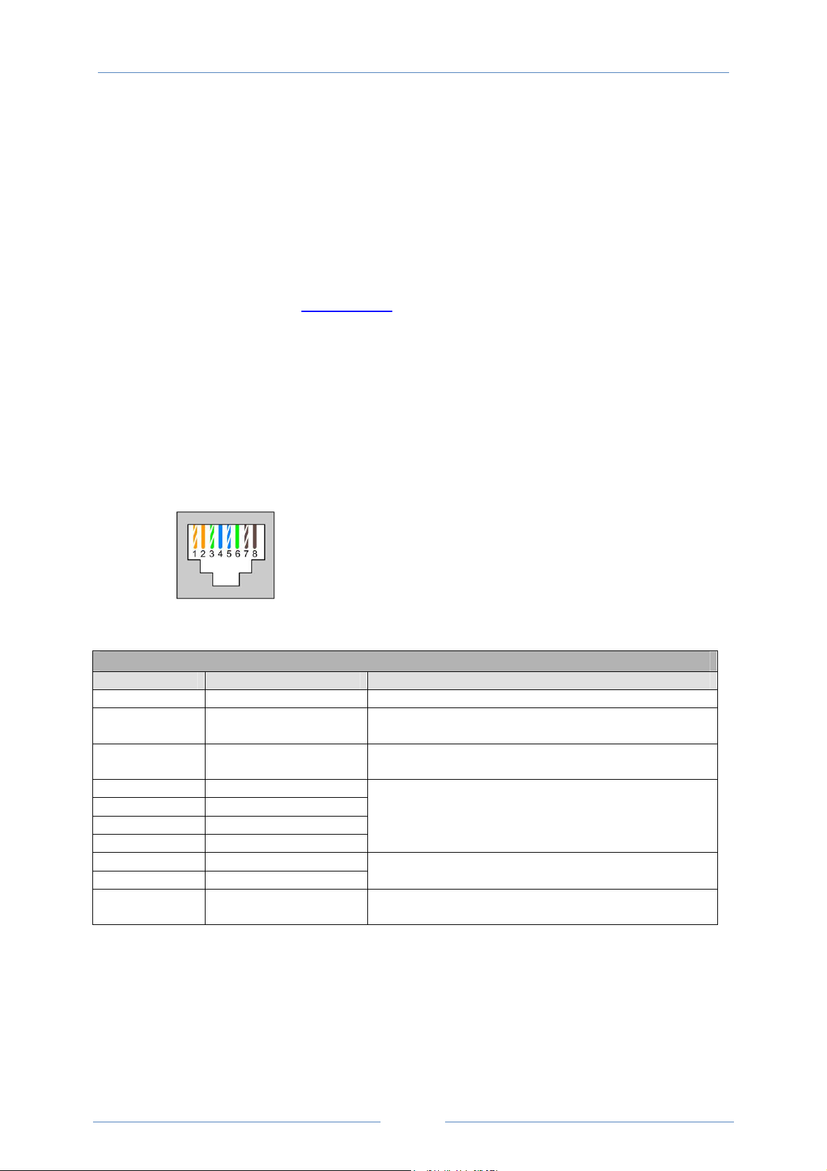
The RJ45 socket is used as CAN signal physical connector with the signals layout as shown blow:
1: CANopen - 2: CANopen +
3: 0V 4: RS485- (Optibus)
5: RS485+ (Optibus) 6: +24V
7: RS485- (Modbus) 8: RS485+ (Modbus)
Optidrive P2 provides the following default COB-ID and functions:
Table 1 : Messages and COB-IDs
Type COB-ID Function
NMT 000h Network management
Sync 080h Synchronous message
COB-ID can be configured to other value.
Emergency 080h + Node address Emergency message
COB-ID can be configured to other value.
PDO1 (TX) 180h + Node address
PDO1 (RX) 200h + Node address
PDO2 (TX) 280h + Node address
PDO2 (RX) 300h + Node address
SDO (TX) 580h + Node address
SDO (RX) 600h + Node address
Error Control 700h + Node address Guarding and Heartbeat function are supported.
Process data object.
PDO1 is pre-mapped and enabled by default.
PDO2 is pre-mapped and disabled by default.
Transmission mode, COB-ID and mapping can be configured.
SDO channel can be used for drive parameter access.
COB-ID can be configured to other value.
Note:
1. The Optidrive P2 SDO channel only supports expedited transmission.
2. The Optidrive P2 can only support up to 2 Process Data Objects (PDO). All PDOs are pre-mapped, however
PDO2 is disabled by default. Table 2 gives the default PDO mapping information.
3. Customer configuration (mapping) will NOT be saved during power down. This means that the CANopen
configuration will restore to its default condition each time the drive is powered up.
PAGE 1
Page 2
CANopen USER GUIDE Beijer Electronics Automation AB
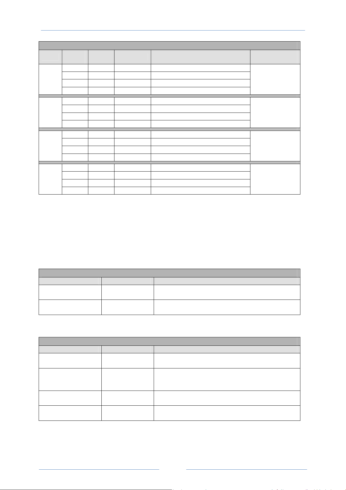
Table 2: PDO Default Mapping
Objects
RX
PDO 1
TX
PDO1
RX
PDO 2
TX
PDO2
No.
1 2000h Unsigned 16 Control command register
2 2001h Integer 16 Speed reference
3 2002h Integer 16 Torque reference
4 2003h Unsigned 16 User ramp reference
1 200Ah Unsigned 16 Drive status register
2 200Bh Integer 16 Motor speed Hz
3 200Dh Unsigned 16 Motor current
4 200Eh Integer 16 Motor torque
1 0006h Unsigned 16 Dummy
2 0006h Unsigned 16 Dummy
3 0006h Unsigned 16 Dummy
4 0006h Unsigned 16 Dummy
1 200Fh Unsigned 16 Motor power
2 2010h Integer 16 Drive temperature
3 2011h Unsigned 16 DC bus value
4 200Ch Integer 16 Motor speed (Internal data format)
* Drive control can only be achieved when P1-12=6
Mapped
Object
Length Mapped Function
Transmission
Type
254
Valid immediately
254
Send after receiving
RX PDO1
254
254
PDO transmission type:
Various transmission modes can be selected for each PDO.
For RX PDO, the following modes are supported:
Table 3: RX PDO Transmission Mode
Transmission Type Mode Description
0 – 240 Synchronous
254, 255 Asynchronous
For TX PDO, the following modes are supported:
Table 4: TX PDO Transmission Mode
Transmission Type Mode Description
0 Acyclic synchronous
1 - 240 Cyclic synchronous
254 Asynchronous
255 Asynchronous
The received data will be transferred to the drive active control
register when the next sync message is received.
The received data will be transferred to the drive active control
register immediately without delay.
TX PDO will only be sent out if the PDO data has changed and
PDO will be transmitted on reception of SYNC object
TX PDO will be transmitted synchronously and cyclically. The
transmission type indicates the number of SYNC object that are
necessary to trigger TX PDO.
TX PDO will only be transferred once corresponding RX PDO has
been received.
TX PDO will only be transferred anytime if PDO data value has
changed.
PAGE 2
Page 3

CANopen USER GUIDE Beijer Electronics Automation AB
CANopen specific Object table:
Table 5: Communication Profile Object Dictionary
Index
1000h 0 Device type RO Unsigned 32 N 0
1001h 0 Error register RO Unsigned 8 N 0
1002h 0 Manufacturer status register RO Unsigned 16 N 0
1005h 0 COB-ID Sync RW Unsigned 32 N 00000080h
1008h 0 Manufacturer device name RO String N ODP2
1009h 0 Manufacturer hardware version RO String N x.xx
100Ah 0 Manufacturer software version RO String N x.xx
100Ch 0 Guard time [1ms] RW Unsigned 16 N 0
100Dh 0 Life time factor RW Unsigned 8 N 0
1014h 0 COB-ID EMCY RW Unsigned 32 N 00000080h+Node ID
1015h 0 Inhibit time emergency [100us] RW Unsigned 16 N 0
1017h 0 Producer heart beat time [1ms] RW Unsigned 16 N 0
1018h
1200h
1400h
1401h
1600h
1601h
1800h
1801h
1A00h
Sub
index
0 Identity object No. of entries RO Unsigned 8 N 4
1 Vendor ID RO Unsigned 32 N 0x0000031A
2 Product code RO Unsigned 32 N Drive depended
3 Revision number RO Unsigned 32 N x.xx
4 Serial number RO Unsigned 32 N e.g. 1234/56/789
0 SDO parameter No. of entries RO Unsigned 8 N 2
1 COB-ID client -> server (RX) RO Unsigned 32 N 00000600h+Node ID
2 COB-ID server -> client (TX) RO Unsigned 32 N 00000580h+Node ID
0 RX PDO1 comms param No. of entries RO Unsigned 8 N 2
1 RX PDO1 COB-ID RW Unsigned 32 N 40000200h+Node ID
2 RX PDO1 transmission type RW Unsigned 8 N 254
0 RX PDO2 comms param No. of entries RO Unsigned 8 N 2
1 RX PDO2 COB-ID RW Unsigned 32 N C0000300h+Node ID
2 RX PDO2 transmission type RW Unsigned 8 N 0
0 RX PDO1 mapping / No. of entries RW Unsigned 8 N 4
1 RX PDO1 1st mapped object RW Unsigned 32 N 20000010h
2 RX PDO1 2nd mapped object RW Unsigned 32 N 20010010h
3 RX PDO1 3rd mapped object RW Unsigned 32 N 20020010h
4 RX PDO1 4th mapped object RW Unsigned 32 N 20030010h
0 RX PDO2 mapping / No. of entries RW Unsigned 8 N 4
1 RX PDO2 1st mapped object RW Unsigned 32 N 00060010h
2 RX PDO2 2nd mapped object RW Unsigned 32 N 00060010h
3 RX PDO2 3rd mapped object RW Unsigned 32 N 00060010h
4 RX PDO2 4th mapped object RW Unsigned 32 N 00060010h
0 TX PDO1 comms param No. of entries RO Unsigned 8 N 3
1 TX PDO1 COB-ID RW Unsigned 32 N 40000180h+Node ID
2 TX PDO1 transmission type RW Unsigned 8 N 254
3 TX PDO1 Inhibit time [100us] RW Unsigned 16 N 0
0 TX PDO2 comms param No. of entries RO Unsigned 8 N 3
1 TX PDO2 COB-ID RW Unsigned 32 N C0000280h+Node ID
2 TX PDO2 transmission type RW Unsigned 8 N 0
3 TX PDO2 Inhibit time [100us] RW Unsigned 16 N 0
0 TX PDO1 mapping / No. of entries RW Unsigned 8 N 4
1 TX PDO1 1st mapped object RW Unsigned 32 N 200A0010h
2 TX PDO1 2nd mapped object RW Unsigned 32 N 200B0010h
3 TX PDO1 3
Function Access Type
rd
mapped object RW Unsigned 32 N 200D0010h
PDO
Map
Default value
PAGE 3
Page 4

CANopen USER GUIDE Beijer Electronics Automation AB
4 TX PDO1 4th mapped object RW Unsigned 32 N 200E0010h
0 TX PDO2 mapping / No. of entries RW Unsigned 8 N 4
1 TX PDO2 1st mapped object RW Unsigned 32 N 200F0010h
1A01h
2 TX PDO2 2nd mapped object RW Unsigned 32 N 20100010h
3 TX PDO2 3rd mapped object RW Unsigned 32 N 20110010h
4 TX PDO2 4th mapped object RW Unsigned 32 N 200C0010h
Manufacturer specific Object table:
ODP2 manufacturer specific object dictionary is defined as follows:
Table 6: Manufacturer Specific Profile Area
Index
2000h 0 Control command register RW Unsigned 16 Y
2001h 0 Speed reference RW Integer 16
2002h 0 Torque reference RW Integer 16
2003h 0 User ramp reference RW Unsigned 16
2004h 0 Speed reference (internal format) RW Integer 16
2005h
…
2009h
200Ah 0 Drive status register RO Unsigned 16
200Bh 0 Motor speed Hz RO Unsigned 16
200Ch 0 Motor speed (internal format) RO Unsigned 16
200Dh 0 Motor current RO Unsigned 16
200Eh 0 Motor torque RO Integer 16
200Fh 0 Motor power RO Unsigned 16
2010h 0 Drive temperature RO Integer 16
2011h 0 DC bus value RO Unsigned 16
2012h 0 Digital input status RO Unsigned 16
2013h 0 Analog input 1 (percentage) RO Unsigned 16
2014h 0 Analog input 2 (percentage) RO Unsigned 16
2015h 0 Analog output 1 RO Unsigned 16
2016h 0 Analog output 2 RO Unsigned 16
2017h 0 relay output 1 RO Unsigned 16
2018h 0 relay output 2 RO Unsigned 16
2019h 0 relay output 3 (extension card) RO Unsigned 16
201Ah 0 relay output 4 (extension card)
201Bh 0 relay output 5 (extension card)
201Ch 0 Scope channel 1 (internal format)
201Dh 0 Scope channel 2 (internal format)
201Eh 0 Scope channel 3 (internal format)
201Fh 0 Scope channel 4 (internal format)
2020h 0 User data 1 RW Unsigned 16 Y
2021h 0 User data 2 RW Unsigned 16 Y
2022h 0 User data 3 RW Unsigned 16 Y
2023h 0 User data 4 RW Unsigned 16 Y
2024h 0 User data 5 RW Unsigned 16 Y
2025h 0 User data 6 RW Unsigned 16 Y
2026h 0 User data 7 RW Unsigned 16 Y
2027h 0 User data 8 RW Unsigned 16 Y
2028h 0 User data 9 RW Unsigned 16 Y
2029h 0 User data 10 RW Unsigned 16 Y
Sub
index
0 Reserved RW Unsigned 16
Function Access Type
RO Unsigned 16
RO Unsigned 16
RO Unsigned 16
RO Unsigned 16
RO Unsigned 16
RO Unsigned 16
PDO
Map
Y
Y
Y
Y
Y
Y
Y
Y
Y
Y
Y
Y
Y
Y
Y
Y
Y
Y
Y
Y
Y
Y
Y
Y
Y
Y
Y
Remark
PAGE 4
Page 5

CANopen USER GUIDE Beijer Electronics Automation AB
202Ah 0 User data 11 RW Unsigned 16 Y
202Bh 0 User data 12 RW Unsigned 16 Y
202Ch 0 User data 13 RW Unsigned 16 Y
202Dh 0 User data 14 RW Unsigned 16 Y
202Eh 0 User data 15 RW Unsigned 16 Y
202Fh 0 User analog output 1 RW Unsigned 16 Y
2030h 0 User analog output 2 RW Unsigned 16 Y
2031h 0 Reserved RW Unsigned 16 Y
2032h 0 Reserved RW Unsigned 16 Y
2033h 0 User relay output 1 RW Unsigned 16 Y
2034h 0 User relay output 2 RW Unsigned 16 Y
2035h 0 User relay output 3 RW Unsigned 16 Y
2036h 0 User relay output 4 RW Unsigned 16 Y
2037h 0 User relay output 5 RW Unsigned 16 Y
2038h 0 Reserved RO Unsigned 16 Y
2039h 0 Reserved (P0-80) RO Unsigned 16 Y
203Ah 0 Kilowatt hours (Can be reset by user) RO Unsigned 16 Y
203Bh 0 Megawatt hours (Can be reset by user) RO Unsigned 16 Y
203Ch 0 KWh meter RO Unsigned 16 Y
203Dh 0 MWh meter RO Unsigned 16 Y
203Eh 0 Total run hours RO Unsigned 16 Y
203Fh 0 Total run minute/second RO Unsigned 16 Y
2040h 0 Current run hours (Since last enable) RO Unsigned 16 Y
2041h 0 Current run minute/second RO Unsigned 16 Y
2042h 0 Time to next service RO Unsigned 16 Y
2043h 0 Room Temperature RO Unsigned 16 Y
2044h 0 Speed controller reference RO Unsigned 16 Y
2045h 0 Torque controller reference RO Unsigned 16 Y
2046h 0 Digital pot speed reference RO Unsigned 16 Y
2065h 0 P1-01 RW - N 2000h + 101d
… … Group 1 parameters RW - N …
2072h 0 P1-14 RW - N 2000h + 114d
20C9h 0 P2-01 RW - N 2000h + 201d
… … Group 2 parameters RW - N …
20F0h 0 P2-40 RW - N 2000h + 240d
212Dh 0 P3-01 RW - N 2000h + 301d
… … Group 3 parameters RW - N …
213Ah 0 P3-14 RW - N 2000h + 314d
2191h 0 P4-01 RW - N 2000h + 401d
… … Group 4 parameters RW - N …
219Ch 0 P4-12 RW - N 2000h + 412d
21F5h 0 P5-01 RW - N 2000h + 501d
… … Group 5 parameters RW - N …
2202h 0 P5-14 RW - N 2000h + 509d
2259h 0 P6-01 RW - N 2000h + 601d
… … Group 6 parameters RW - N …
2276h 0 P6-30 RW - N 2000h + 630d
22BDh 0 P7-01 RW - N 2000h + 701d
… … Group 7 parameters RW - N …
22CDh 0 P7-17 RW - N 2000h + 715d
PAGE 5
Page 6

CANopen USER GUIDE Beijer Electronics Automation AB
2321h 0 P8-01 RW - N 2000h + 801d
… … Group 8 parameters RW - N …
232Fh 0 P8-15 RW - N 2000h + 815d
2385h 0 P9-01 RW - N 2000h + 901d
… … Group 9 parameters RW - N …
23ADh 0 P9-41 RW - N 2000h + 941d
23E8h 0 Scope index 12 RW - N 2000h + 1000d
23E9h 0 Scope index 34 RW - N 2000h + 1001d
Drive Specific Object Reference:
Object
2000h : Control command register
2000h Control Command Register
Bit 15 ~ Bit 4 Bit 3 Bit 2 Bit 1 Bit 0
Reserved Coast stop Reset Fast stop Run
If bit 0 is set, the drive will start to run provided that specified condition is met.
If bit 1 is set, the drive will carry out a fast stop. This bit will override the run bit if set
If bit 3 is set, the drive will carry out a coast stop. This bit will override the run and fast stop bits if set.
Bit 2 is used to reset the drive under trip conditions. This reset function is edge active (0 1)
Object
2001h : Speed reference (Hz)
The data value of this object provides the speed reference in Hz format. Data includes once decimal place.
For example, a data value of 500 equates to a speed reference of 50.0Hz. Similarly, a data value of 125
equates to a speed reference of 12.5Hz. If the data value is set to -1234 (0xFB2E), the speed reference will be -
123.4Hz.
Object
2002h : Torque reference (%)
The data value of this object provides the torque reference as a percentage. The data includes one decimal
place. For example, a data value of 500 equates to a torque reference of 50.0% of the motor rated torque. If
the data value is 1250, the resulting torque reference will be 125%
Object
2003h : User ramp reference (0.01s)
The data value of object this set the user ramp time. Value contains two decimal places.
For example, if the data value is 30, the resulting user ramp time will be 0.30s. If data value is 1234, the
resulting ramp time will be 12.34s
Object
2004h : Speed reference (IDL internal format)
The data value of this object provides the speed reference in IDL internal data format. This provides a higher
resolution control result.
If the motor base frequency <= 100Hz, data value 3000 means the speed reference is set to 50Hz.
If the motor base frequency <= 200Hz, data value 3000 means the speed reference is set to 100Hz.
If the motor base frequency > 200Hz, data value 3000 means the speed reference is set to 200Hz.
PAGE 6
Page 7

CANopen USER GUIDE Beijer Electronics Automation AB
Object
200Ah : Drive status register
200Ah Drive Status Register
Bit 15 ~ Bit 8 Bit 7,6,5 Bit 4 Bit 3 Bit 2 Bit 1 Bit 0
Trip code if bit 1 is set to 1 N/A
Service
due
Inhibit
If bit 0 is set, drive is in run condition.
If bit 1 is set, drive is in trip condition.
If bit 2 is set, drive is in hand control mode (HVAC drive only)
If bit 3 is set, drive is in inhibit mode.
If bit 4 is set, this indicates that drive/system is due to service
Bit 5 to Bit 7 are reserved. (These bits may be used at a later stage)
Bit 8 to Bit 15 provide the error/trip code when drive is in trip condition. (Error code list is not provided here)
Object
200Bh : Motor speed (Hz)
The data value of this object provides the motor speed information in Hz unit. The data includes one decimal
place.
For example, a data value of 500=50.0Hz, -125=-12.5Hz
Hand
mode
Trip Run
Object
200Ch : Motor speed (IDL internal format)
The data value of this object provides the motor speed information in IDL internal data format. See object
2004h for more information about this speed format
Object
200Dh : Motor current (A)
The data value of this object provides motor current information. The value contains one decimal place.
For example, if the data value is 30, this means the motor current is 3.0A
Object
200Eh : Motor torque (Q12)
The data value of this object provides motor output torque information. The value is in Q12 format, 4096 =
100%.
Object
200Fh : Motor power (kW)
The data value of this object provides motor output power information. The value contains two decimal places.
For example, 1234=12.34kW
--- END ---
PAGE 7
 Loading...