

Page 1

possible injury or death.
avoided, could result in damage to property.
use of t
he BFI
, including the spe
cified environmental limitations.
Do not perform any flash test or voltage withstand test on the
BFI
. Any electrical measurements required should be carried out with
BFI disconnected.
driv
e power terminals pri
or to commencing any work.
Where supply to the drive is through a plug and socket connector, do not disconnect until 10 minutes have elapsed after turni
ng off the supply.
machine manufacturer
is responsible for providing a main switch and ensuring the electrical equipment complies with EN60204
-1.
subject to a risk assessment and further protection provided where neede
d. The driven motor can
start at power up if the enable input signal is present.
out any work on the D
rive
, Motor or Motor cabl
e whilst the input power is still applied.
prior to machine start up.
Do not activate the automatic fault reset function on any systems whereby this may cause a potentially dangerous situa
tion.
The BFI has an In
gress Protection rating of IP20 or IP66 depending on the model.
IP20 units must be installed in a suitable enclosure.
drilling may lead to damage.
BFI are intended for indoor use only.
Relative humi
dity must be less than 95
% (non
-
condensing).
Ensure that the supply voltage, frequency and no. of phases (1 or 3 phase) correspond to the rating of the
BFI as delivered.
Never connect the mains power supply to the Output terminals U, V, W.
Do not ins
tall any type of automati
c switchgear between the drive and the motor
Ensure that all terminals are tightened to the appropria
te t
orque setting
assistance.
Beijer Electronics Frequency Inverter BFI-E3 KI00369B 2019-09
1 Start-up document
This document is a simple start-up guide describing basic functionality of the drive BFIE3, firmware 3.08. Detailed explanations are to be read in User Manual BFI-E3 and is
attached with the drive itself. but also possible to download from www.
beijerelectronics.se or .no or .dk or .de or .com or .com .tr/ or .tw or .co.uk/
2 Important Safety Information
Read IMPORTANT SAFETY INFORMATION below, especially Warnings and Caution.
Danger : Indicates a risk of electric shock, which, if not
avoided, could result in damage to the equipment and
This variable speed drive product is intended for professional incorporation into complete equipment or systems as part of a fixed installation. If installed
incorrectly it may present a safety hazard. The BFI uses high voltages and currents, carries a high level of stored electrical energy, and is used to control
mechanical plant that may cause injury. Close attention is required to system design and electrical installation to avoid hazards in either normal operation
or in the event of equipment malfunction. Only qualified electricians are allowed to install and maintain this product.
System design, installation, commissioning and maintenance must be carried out only by personnel who have the necessary training and experience.
They must carefully read this safety information and the instructions in this Guide and follow all information regarding transport, storage, installation and
Electric shock hazard! Disconnect and ISOLATE the BFI before attempting any work on it. High voltages are present at the terminals and within the
drive for up to 10 minutes after disconnection of the electrical supply. Always ensure by using a suitable multimeter that no voltage is present on any
Ensure correct earthing connections. The earth cable must be sufficient to carry the maximum supply fault current which normally will be limited by the
fuses or MCB. Suitably rated fuses or MCB should be fitted in the mains supply to the drive, according to any local legislation or codes.
Do not carry out any work on the drive control cables whilst power is applied to the drive or to the external control circuits.
Within the European Union, all machinery in which this product is used must comply with Directive 98/37/EC, Safety of Machinery. In particular, the
The level of integrity offered by the BFI control input functions – for example stop/start, forward/reverse and maximum speed is not sufficient for use in
safety-critical applications without independent channels of protection. All applications where malfunction could cause injury or loss of life must be
The STOP function does not remove potentially lethal high voltages. ISOLATE the drive and wait 10 minutes before starting any work on it. Never carry
The BFI can be programmed to operate the driven motor at speeds above or below the speed achieved when connecting the motor directly to the mains
supply. Obtain confirmation from the manufacturers of the motor and the driven machine about suitability for operation over the intended speed range
Danger : Indicates a potentially hazardous
situation other than electrical, which if not
When mounting the drive, ensure that sufficient cooling is provided. Do not carry out drilling operations with the drive in place, dust and swarf from
The entry of conductive or flammable foreign bodies should be prevented. Flammable material should not be placed close to the drive
Wherever control cabling is close to power cabling, maintain a minimum separation of 100 mm and arrange crossings at 90 degrees
Do not attempt to carry out any repair of the BFI. In the case of suspected fault or malfunction, contact your local Beijer Electronics office for further
Beijer Electronics a company in the Beijer Electronics Group
Parent Company (Reg. office) Subsidiaries
Beijer Electronics AB Norway, Drammen: Beijer Electronics AS, +47 32 24 30 00
P.O. Box 426 Denmark, Copenhagen: Beijer Electronics A/S, +45 75 76 66
SE-201 24 MALMÖ, SWEDEN Germany, Nürtingen: Beijer Electronics GmbH, +49 7022 9660 0
Telephone +46 40 35 86 00 UK, Castle Donington: Beijer Electronics Products, +44 (0)845519 5430
Fax +46 40 93 23 01 France, Champlan: Beijer Electronics +33 (0)1 69 10 22 42
Visiting address: Stora Varvsgatan 13a, Malmö Turkey Istanbul: Beijer Electronics ve Ticaret A.s 0090 216 366 32 0200
Sida 1 (24)
Page 2

Beijer Electronics Frequency Inverter BFI-E3 KI00369B 2019-09
3 Contents
1 START-UP DOCUMENT 1
2 IMPORTANT SAFETY INFORMATION 1
3 CONTENTS 2
4 INSTALLATION 3
4.1 PHYSICAL DIMENSIONS IP20 ...................................................................................................................................... 3
4.2 PHYSICAL DIMENSIONS IP66 ...................................................................................................................................... 4
4.3 FUSES, CABLE DIMENSIONS AND POWER LOSES ........................................................................................................ 5
4.4 OVERVIEW POWER INPUT AND OUTPUT TERMINALS .................................................................................................. 5
4.5 INSTALLATION OF POWER SUPPLY, GROUNDING AND MOTOR CABLE ........................................................................ 6
4.6 BRAKE TRANSISTOR AND EXTERNAL BRAKE RESISTOR ............................................................................................. 7
4.7 OVERVIEW CONTROL INPUTS/OUTPUTS ..................................................................................................................... 8
5 BASIC PARAMETER SETTING 9
5.1 DIGITAL START IN 2 DIRECTIONS AND 4 FIXED PRESET SPEEDS ............................................................................... 9
5.2 DIGITAL START IN 2 DIRECTIONS AND ANALOG FREQUENCY SET POINT .................................................................. 10
5.3 DIGITAL MOTOR POTENTIOMETER ............................................................................................................................ 10
5.4 DIGITAL START SIGNAL AND FREQUENCY SET POINT BY LED DISPLAY ................................................................... 11
5.5 START/STOP BY INDIVIDUAL SIGNALS ....................................................................................................................... 11
5.6 CONTROL FROM LED DISPLAY ................................................................................................................................. 11
5.7 ANALOG OUTPUT, 0-10 VDC ................................................................................................................................... 12
5.8 DIGITAL OUTPUTS ..................................................................................................................................................... 12
5.9 STYRNING AV MEKANISK HÅLLBROMS I MOTORN ..................................................................................................... 12
5.10 PTC-THERMISTOR .................................................................................................................................................... 12
5.11 VECTOR CONTROL WITH STANDARD INDUCTION MOTOR ......................................................................................... 13
5.12 CURRENT LIMIT CONTROL......................................................................................................................................... 13
5.13 TUNING OF PM-MOTOR ............................................................................................................................................ 13
5.14 MODBUS RTU .......................................................................................................................................................... 14
5.15 CANOPEN ................................................................................................................................................................. 15
5.16 PI-CONTROL ............................................................................................................................................................. 16
5.17 ENERGY OPTIMIZATION FUNCTION ........................................................................................................................... 16
5.18 SPIN START ............................................................................................................................................................... 17
5.19 BFI-SMARTSTICK...................................................................................................................................................... 17
6 KEYPAD 18
6.1 MONITORING FROM KEYPAD .................................................................................................................................... 19
6.2 IP66, MAIN SWITCH, START/STOP SWITCH AND POTENTIOMETER .......................................................................... 20
6.3 EMC-FILTER ............................................................................................................................................................. 20
7 SPECIFICATION 21
8 WARNING AND ALARM CODES 22
Copyright © Beijer Electronics, 2017
This software/documentation/information (below referred to as ‘the material’) is the property of Beijer
Electronics. The holder or user has a non-exclusive right to use the material.
The holder is not allowed to distribute the material to anyone outside his/her organization except in cases
where the material is part of a system that is supplied by the holder to his/her customer.
The material may only be used with products or software supplied by Beijer Electronics. Beijer Electronics
assumes no responsibility for any defects in the material, or for any consequences that might arise from the
use of the material.
It is the responsibility of the holder to ensure that any systems, for whatever applications, which is based on
or includes the material (whether in its entirety or in parts), meets the expected properties or functional
requirements.
Beijer Electronics has no obligation to supply the holder with updated versions.
www.beijer.se www.beijer.no www.beijer.dk www.beijerelectronics.de www.beijerelectronics.com www.beijerelektronik.com.tr 2 (24)
Page 3
Drive
[mm]
0070
0105
Beijer Electronics Frequency Inverter BFI-E3 KI00369B 2019-09
4 Installation
The drive should be mounted in a vertical position only on a flat, flame resistant vibration
free mounting using the integral holes. IP66 is allowed for outdoor mounting. But it is
recommended having an external roof to avoid snow directly on drive. BFI will not start if
ambient temperature is below -20°C. See User Manual BFI-E3 for more details.
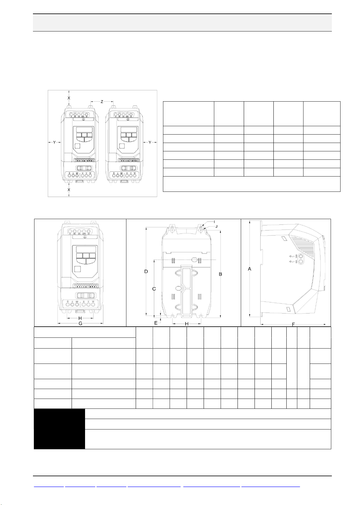
4.1 Physical dimensions IP20
Drive IP-class
and
Size
IP20, size 1 50 50 33 0,14
IP20, size 2 75 50 46 0,27
IP20, size 3 100 50 52 0,74
IP20, size 4 100 50 52 1,48
IP20, size 5 200 25 70 1,28
IP66, All sizes 200 10 0 0
Z means that BFI can be mounted side-by-side. Minimum airflow is
based on maximum output power at 50°C for IP20 and 40°C for IP66.
X [mm]
Above &
Below
Y [mm]
Either
Side
Z [mm]
Between
drives
Minimum
Airflow
[m3/min]
BFI-E3- IP20
1 x 230 V 3 x 380-480 V
0023[0,37-1,5 kW]
0070[1,5-2,2 kW]
0153/ 4,0 kW
No
No
NOTE
www.beijer.se www.beijer.no www.beijer.dk www.beijerelectronics.de www.beijerelectronics.com www.beijerelektronik.com.tr 3 (24)
0022-0041 [0,75-1,5kW]
0041-0095 [1,5-4,0 kW]
0140-0240 [5,5-11kW]
0300-0460 [15-22kW]
0610-0720 [30-37kW]
1x230 BFI-E3-0070 and BFI-E3-0041 are without brake transistor for Size 1 and Size2 with.
Mounting bolts for Size1 to Size 3 are 4xM4 and 4xM8 for Size4 and Size5.
Control Terminal Torque Settings of 0.8Nm.
Power Terminal Torque Settings: Size1-3 = 1 Nm, Size4=2.0 Nm, Size5=4.0 Nm.
size
A
B
C
Height
1 173 160 109 162 5 123 83 50
2 221 207 137 209 5.3 150 110 63 1,7
3 261 246 - 247 6 175 131 80 3,2
4 420 400 - 400 8 212 171 125 8,2 14,8 9,1
5 486 463 226 222 175 18,1
[mm]
[mm]
[mm]
D
[mm]
[mm]
E
F
Depth
[mm]
G
Width
[mm]
H
[mm]
I
J
[mm]
5,5 10
Weight
[kg]
1,0
Page 4
0105
0
Beijer Electronics Frequency Inverter BFI-E3 KI00369B 2019-09
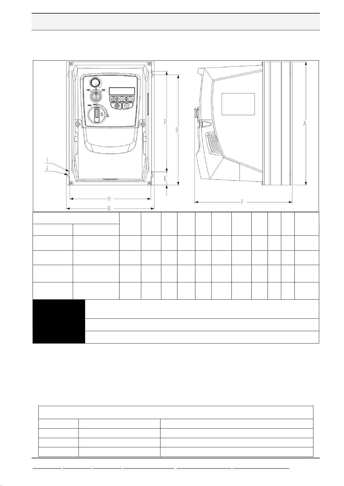
4.2 Physical dimensions IP66
BFI-E3- -IP66
1 x 230 V 3x380-480 V
0023-0070
[0,37-1,5 kW]
0070[1,5-2,2 kW]
0153
[4,0 kW]
NOTE
0022-0041
[0,75-1,5 kW]
0041-0095
[1,5-4,0 kW]
0140-0240
[5,5-11 kW]
0300-018
[15-18 kW]
1x230 V BFI-E3-0070 and 3x400 V BFI-E3-0041 are without brake transistor for Size 1 and Size2
with.
Mounting bolts for Size1 to Size 3 are 4xM4 and 4xM8 for Size 4.
Control Terminal Torque Settings of 0.8Nm. Power Terminal Torque Settings is of 1 Nm.
Drive
size
1 232 207 189 25.0 162 161 149 4.0 8.0 2,5
2 257 220 200 28.5 182 188 176 4.2 8.5 3,5
3 310 277 251,5 33.4 238 210 197.5 4.2 8.5 7,0
4 360 300 33.4 275 240 9,5
A
Height
[mm]
B
[mm]
D [mm]
E
[mm]
F
Depth
[mm]
G
Width
[mm]
H
[mm]
I
[mm]
J
[mm]
IP66 drives are fitted with 3 knockout holes for cable inlet and outlet. If more than 3 cables are
to enter the drive it is possible to have two or more cables going through one gland. This is to
ensure IP66.
Weight
[kg]
Holes and recommended glands are listed in table below. The motor cable does not have to be
attached to the drive with an EMC-gland.
Cable Gland, IP66 Hole Size & recommended glands
Size 1
Size 2 & 3
Size 4
www.beijer.se www.beijer.no www.beijer.dk www.beijerelectronics.de www.beijerelectronics.com www.beijerelektronik.com.tr 4 (24)
Hole sizes Gland PG
3 x 22mm 3 x PG13,5
1 x 22mm and 2 x 27 mm 1 x PG13,5 and 2 x PG21
1 x 22mm and 2 x 40 mm 1 x PG13,5 and 2 x PG29
Page 5
Max Motor
Cable Size,
Cable Size,
Max Motor
Beijer Electronics Frequency Inverter BFI-E3 KI00369B 2019-09
4.3 Fuses, cable dimensions and power loses
200-240V ±10% - Single Phase Input – 3 Phase Output
Output
Power [kW]
Amps Amps mm2 mm2 Amps mm2 m W
0.37 0023 3,7 10 1,5 1,5 2,3 1,5 100 12
0.75 0043 7,5 10 2,5 1,5 4,3 1,5 100 22,5
1.5 0070 12,9 16 2,5 2,5 7,0 1,5 100 50
2.2 0105 19,2 25 6 2,5 10,5 1,5 100 66
4,0 0153 29,2 32 6 4 15,3 1,5 100 120
380-480V ±10% - 3 Phase Input – 3 Phase Output
Output
Power [kW]
Amps Amps mm2 Amps Amps mm2 m W
0.75 0022 3,5 6 1.5 1.5 2.2 1.5 100 22,5
1.5 0041 5,6 6 1.5 1.5 4.1 1.5 100 50
2.2 0058 7,5 10 1.5 1.5 5.8 1.5 100 50
4 0095 11,5 16 2.5 1,5 9.5 1.5 100 120
5.5 0140 17,2 25 4 2,5 14 1.5 100 165
7.5 0180 21,2 25 4 2,5 18 2,5 100 225
11 0240 27,5 32 6 4 24 4 100 330
15 0300 34.2 50 16 6 30 6 100 450
18.5 0390 44.1 50 16 6 39 10 100 550
22 0460 51.9 63 25 10 46 16 100 660
30 0610 64 80 35 16 61 16 100 900
37 0720 76 80 35 16 72 16 100 1110
Recommended choice of cable sizes and fuses follows DIN VDE 0100 paragraph 430
Appendix1, motor cable is copper, way of wiring A1 and E is following SS 424 24 24 edition.
A1 means cable/conductors in some kind of duct in a maximum temperature of 40°C. E means
cable/conductors mounted on a ladder. Calculated at 30°C with 9 or several cables(correction
factor 0,78). All recommended sizes of cable sizes and fuses are recommendations. National
laws and recommendations are to be considered.
BFI-E3
model
BFI-E3
model
Nominal
Input
Current
Nominal
Input
Current
Fuse or
MCB
(type B)
Fuse or
MCB
(type B)
Supply
Cable Size,
A1 40°C
Supply
Cable Size,
A1 40°C
Supply
Cable Size,
E 30°C
Supply
E 30°C
Nominal
Output
Current
Nominal
Output
Current
Motor
Cable Size,
E 30°C
Motor
E 30°C
Cable
Length
Cable
Length
Power
losses
Power
losses
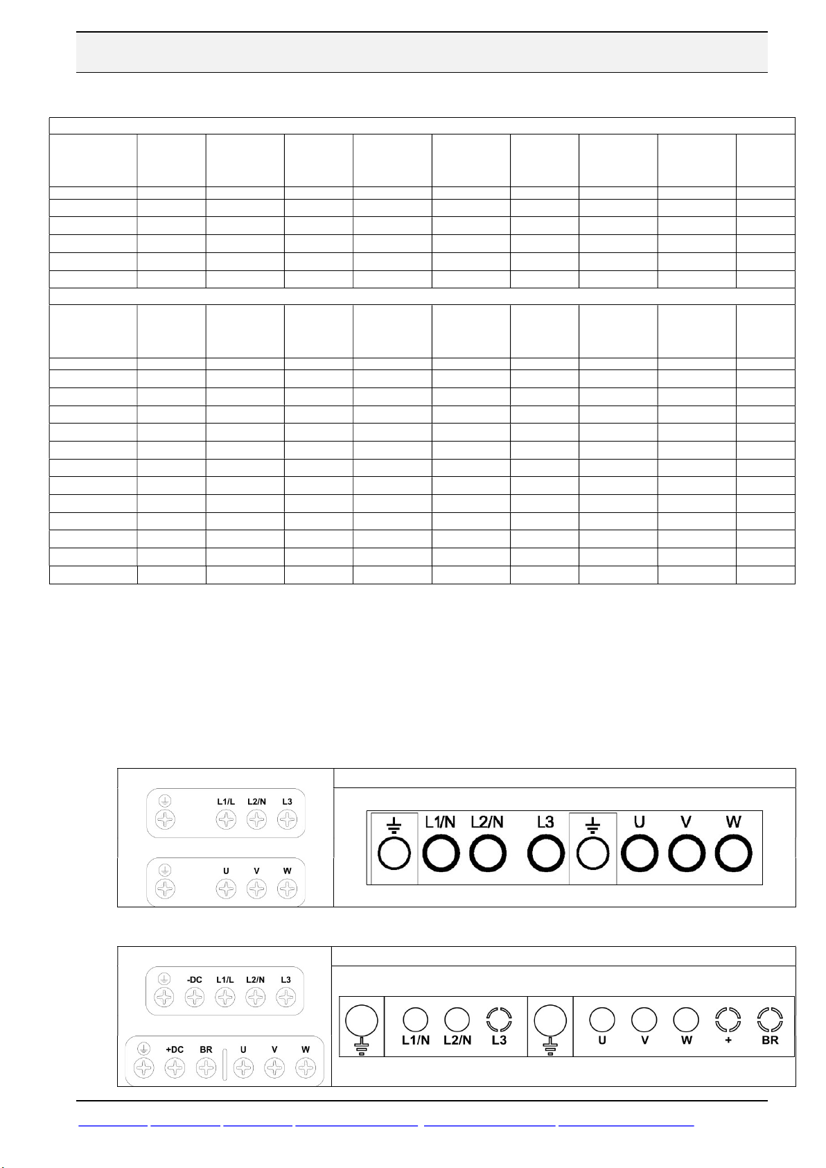
4.4 Overview power input and output terminals
Size 1 Connections
IP20 IP66 (Nema 4X)
Size 2 & 3 & 4 & 5 Connections
IP20 IP66 (Nema 4X)
www.beijer.se www.beijer.no www.beijer.dk www.beijerelectronics.de www.beijerelectronics.com www.beijerelektronik.com.tr 5 (24)
Page 6
400V
230V
690V
400V
STAR DELTA
V
Beijer Electronics Frequency Inverter BFI-E3 KI00369B 2019-09
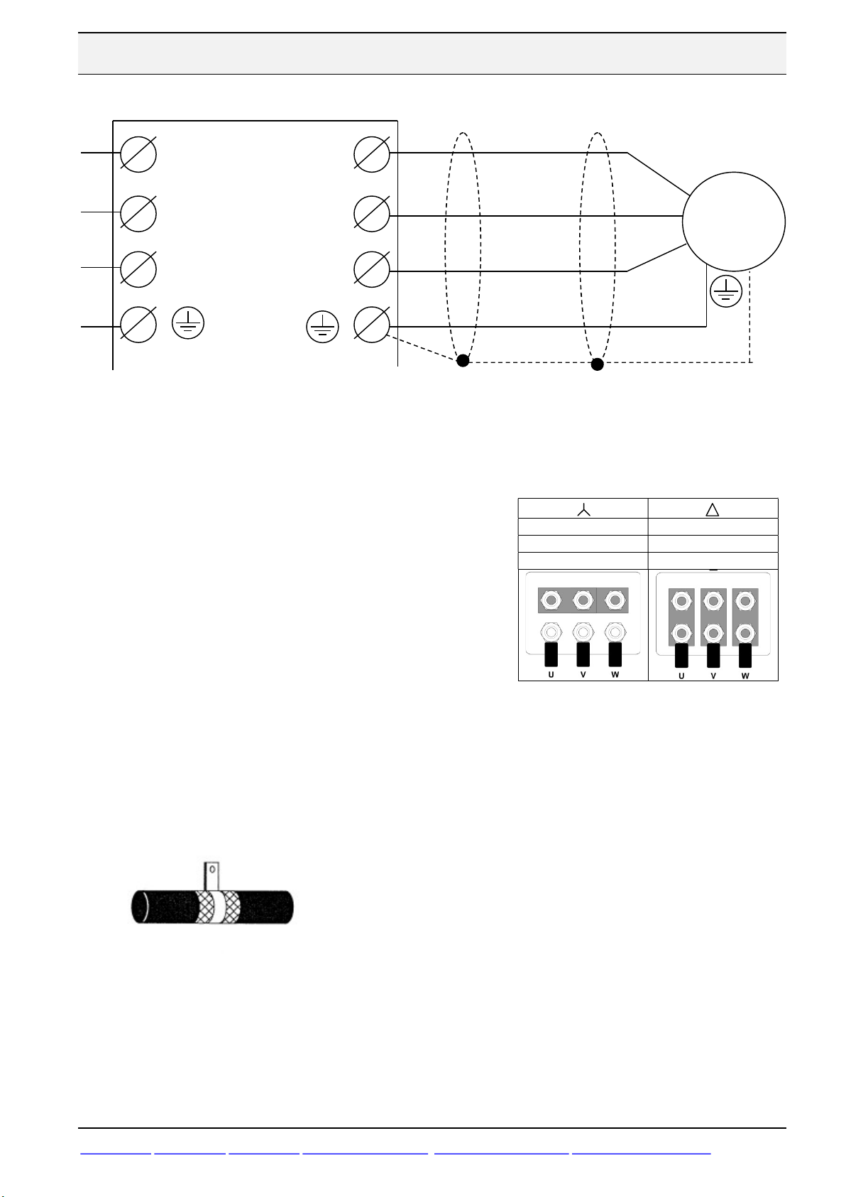
4.5 Installation of power supply, grounding and motor cable
L1/N
L2/N
L3
Drive is to be connected with ground/PE by separate grounding wire.
1-phase power supply should be connected to L1/L, L2/N.
3-phase power supply should be connected to L1, L2 and L3.
Phase sequence of power supply is not important and cable doesn’t have to be a shielded.
Protective grounding of motor is connected to drive
Motor cable should be connected to U, V, W.
Inverter Power supply 3*400 VAC:
U
M ~
W
- Rated voltage of motor 230/400, Star connection
- Rated voltage of motor 400/660, Delta connection
Inverter Power supply 1*230 VAC
- Rated voltage of motor 230/400, Delta connection
Motor cable must be a shielded cable to fulfill EMC requirements. Example of cables to be
used are RKFK, Ölflex Classic 100 CY, FKKJ-EMC, or similar.
Shield of the motor cable should be connected to ground/earth in both ends. On motor side
an EMC-gland is to be used.
Shield of motor cable is to be connected to ground terminal in the drive itself. For IP20
drives the shield can instead be clamped to the mounting plate with a clip.
Motor must also be well attached into the mechanical frame of the machinery and have the
same potential as the electrical cabinet. Separate earth connection might be necessary.
Motor cable should avoid to be installed close to telephone-, network- or signal wiring.
Minimum distance is 30 cm.
www.beijer.se www.beijer.no www.beijer.dk www.beijerelectronics.de www.beijerelectronics.com www.beijerelektronik.com.tr 6 (24)
Page 7

BFI power [ohm]
Beijer Electronics Frequency Inverter BFI-E3 KI00369B 2019-09
4.6 Brake transistor and external brake resistor
If a larger amount of regenerate power is being produced than the BFI can handle at stop function AC
Flux Braking can be used. Means that motor is being over excitated during stop and used as brake
resistor. Note that heat of motor will increase and it only works during deceleration. Put parameter P05=3 to activate AC Flux braking.
If AC Flux braking is not enough BFI from Size2 has a dynamic brake transistor and an optional
external braking resistor can be connected to +DC and BR when required. The brake resistor circuit
should be protected by a suitable thermal protection circuit. The –DC, +DC and BR connections are
blanked off by plastic tabs when sent from the factory. The plastic tabs can be removed if/when
required.
Table shows models with built-in brake transistor suggestion of brake resistors.
- Internal resistor, OD-BR100-BFI is mounted inside BFI IP20 and is activated and
protected from overload by setting of P34=1.
- External resistor must always be used together with a slow external overload
protection and P34=2. Table shows setting current of the external overload
protection.
Minimum resistance
Drive model
Voltage BFI-E3
0070[1,5kW]
1-phase
230 VAC
3-phase
400 VAC
0105[2,2kW]
0153[4,0kW]
0041[1,5kW]
0058[2,2kW]
0095[4,0kW]
0140[5,5kW]
0180[7,5kW]
0240[11 kW]
0300 [15kW]
0390 [18kW]
0460[22kW] 28
0610[30kW] 21
0720[37kW] 17
when regenerated
power is equal with
101 OD-BR100-BFI P34=1 0,2 12 100
69
25 OD-BR100-BFI P34=1 0,2 12 100
406
277
152
111
81
55
41
33
Brakeresistor to be used
Setting
Name
OD-BR100-BFI
BSD600R75-4 2,8 A 0,6 75
OD-BR100-BFI P34=1 0,2 12 100
2 BSD600R140-4
connected in serial
OD-BR100-BFI P34=1 0,2 12 100
2 BSD600R82-4
connected in seriell
OD-BR100-BFI P34=1 0,2 12 100
BSD600R140-4 2,1 A 0,6 - 140
OD-BR100-BFI P34=1 0,2 12 100
BSD600R82-4 2,7A 0,6 - 82
OD-BR100-BFI P34=1 0,2 12 100
BSD600R75-4 2,8 A 0,6 - 75
OD-BR100-BFI P34=1 0,2 12 100
2 BSD-600R140-4
connected in parallel
2 pieces of BSD-
2000R13-4 connected
in serial
overload
protection
P34=1 0,2 12 100
2,1 A 1,2
2,7 A 1,2 - 164
4,1 A 1,2 - 70
12,4 A 4,0 - 26
Power resistor [kW]
Medel
Peak for
0,125 sec
- 280
Resistans
[ohm]
If other brake resistor than OD-BR100-BFI is used an external overload protection must be connected
between BFI and resistor. Put parameter P34=2 and design the protection using below formula:
www.beijer.se www.beijer.no www.beijer.dk www.beijerelectronics.de www.beijerelectronics.com www.beijerelektronik.com.tr 7 (24)
Setting of external overload protection = I = √P/R
Page 8

2
6
7
8
9
4
6
7
1
8
Beijer Electronics Frequency Inverter BFI-E3 KI00369B 2019-09
4.7 Overview control inputs/outputs
Picture below shows an overview of control signals for the drive and factory set functionality
when the internal 24 VDC of the BFI is being used.
+24 VDC
DI1: Start signal
DI2: Fwd or Rev direction
DI3: Preset speed1
+10 VDC
AI1:Analog reference
0 VDC
Picture below shows an overview of control signals for the drive and factory set functionality
when an external 24 VDC is being used.
+24 VDC
DI1: Start signal
10
11
0-10 V output,
Motor speed
0 V reference
Relay Output,
No Alarm
0-10 V output,
Motor speed
24 VDC
Extern 0V
DI2: Fwd or Rev riktning
DI3: Preset speed1
+10 VDC
AI1:Analog referens
0 VDC
10
11
0 V reference
Relay Output,
No Alarm
www.beijer.se www.beijer.no www.beijer.dk www.beijerelectronics.de www.beijerelectronics.com www.beijerelektronik.com.tr 8 (24)
Page 9

meter
settng
meter
Default
settng
2
3
4 6
1
Beijer Electronics Frequency Inverter BFI-E3 KI00369B 2019-09
5 Basic Parameter setting
The basic parameter setting that always is to be checked or modified is listed below:
Para-
P-01
P-02
P-03
P-04
P-07
P-08
P-09
P-12
P-13
P-14
P-17 Switching Frequency 8 or 16 kHz
Maximum Frequency
Minimum Frequency
Acceleration Time
Deceleration Time
Motor Rated Voltage
Motor Rated Current
Motor Rated Frequency
Command Source
Operating Mode select
Parameter Access
Name Default
50 Hz If P-10, Motor rated speed, ≠ 0 unit is rpm instead of Hz.
0 Hz
5,0 sec Acceleration ramptime from 0 to 50 Hz.
5,0 sec Deceleration ramptime from 50 to 0 Hz.
230/400 V
- Put rated current of motor from motor nameplate in unit A.
50 Hz 50 Hz Put rated frequecy of motor from motor nameplate in unit Hz.
0 0
0
0 201
To be set Function
Set to some few Hz to ensure torque in motor. If P-10, Motor
rated speed, ≠ 0 unit is rpm instead of Hz.
Put rated voltage of motor from motor nameplate in unit V.
0: Control by digital and/or analog signals.
1: Control from Keypad.
0: Industrial Mode => 150% overload and constant torque.
1: Pump mode => 110 % overload and variable torque.
2: Fan mode => 110 % overload, Spin start, variable torque.
Normally only parameters P-01 to P-14 are accessable. All
other parameters are accessable with this P14=201.
Keep as low as possible. Higher value decreas audible noise in
motor but increase losses in drive.
5.1 Digital start in 2 directions and 4 fixed Preset speeds
+24 VDC
DI1: Start signal
DI2: Direction
DI3: Preset speed
AI1: Preset speed
Status
DI1 DI2 DI3 AI1
0 0 any any
0 1 0 0
0 1 1 0 Reverse & PreSpeed 2
0 1 0 1 Reverse & PreSpeed 3
0 1 1 1 Reverse & PreSpeed 4
1 0 0 0 Forward & PreSpeed 1 (P-20)
1 0 1 0 Forward & PreSpeed 2 (P-21)
1 0 0 1 Forward & PreSpeed 3 (P-22)
1 0 1 1 Forward & PreSpeed 4 (P-23)
1 1 0 0 Reverse & PreSpeed 1
1 1 1 0 Reverse & PreSpeed 2
1 1 0 1 Reverse & PreSpeed 3
1 1 1 1 Reverse & PreSpeed 4
P15 = 8 P15 = 9
No output from drive
No output from drive
Action
Reverse & PreSpeed 1
No output from drive
Para-
P-12
P-15
P-20 Preset Speed 1 5,0 Hz
P-21 Preset Speed 2 25,0 Hz
P-22 Preset Speed 3 40,0 Hz
P-23 Preset Speed 4 50,0 Hz
www.beijer.se www.beijer.no www.beijer.dk www.beijerelectronics.de www.beijerelectronics.com www.beijerelektronik.com.tr 9 (24)
Name
Command Source
Input Selection
To be set
0 0 0= Control by digital and analog signals.
0 8 or 9
8 = Startsignal / Direction signal / Digital setspeed.
9 = Start Forward / Start Reverse / Digital setspeed.
Can be set between P-02 (Minimum speed) and P-01 (Maximum speed).
If P10=0 then values are entered in Hz.
If P10>0 values are entered as rpm.
Function
Page 10

meter
settng
set
10
Type of
=
input is
4
1
4 5 7
0 VDC
+10 VDC
mA
Beijer Electronics Frequency Inverter BFI-E3 KI00369B 2019-09
5.2 Digital start in 2 directions and analog frequency set point
Start of drive is done by either Start- and Direction signals or Start Forward/Start Reverse. Third
digital input decides whether Preset speed1, P-20 or analog input is valid. If 4-20 mA is to be used
current must flow into terminal 6 and out on terminal 7.
+24 VDC
DI1: Start signal
DI2: Direction
DI3: Preset speed1
Analog reference
4-20
Para-
P-01
P-02
P-12
P-15
P-16
P-20 Preset Speed 1 5,0 Hz
P-35 Analog Input Scaling 100 %
Name Default
Maximum Frequency
Minimum Frequency
Command Source
Input Selection
Analog Input 1
Configuration
50 Hz Maximum output frequency. If P-10 Motor rated speed, ≠ 0 unit is rpm.
0 Hz
0 0 0= Control by digital and analog signals.
0
U 0-
To be
analog
input
decides
Status
DI1 DI2 DI3
0 0 any
0 1 0
0 1 1 Reverse & PreSpeed 1
1 0 0 Forward & Analog speed Forward & Analog speed
1 0 1 Forward & PreSpeed 1 Forward & PreSpeed 1
1 1 0 Reverse & Analog speed
1 1 1 Reverse & PreSpeed1
No output from drive
P15 = 0 P15 = 5
Action
No output from drive
Reverse & Analog speed
No output from drive
Function
Minimum output frequency. If P-10, Motor rated speed, ≠ 0 unit is rpm instead
of Hz. P-02 will be output frequency at 0 V or 4 mA setpoint.
0 = Digital Startsignal / Digital Direction signal / Analog setspeed.
5 = Start Forward / Start Reverse / Analog setspeed.
U 0-10 = 0 to 10 VDC,
A 0-20 = 0 to 20mA.
b-10-10 = -10 to 10 VDC. Sign decides rotationdirection.
t 4-20 = 4 to 20mA. Trip if signal level < 3mA.
r 4-20 = 4 to 20mA, Stop and Trip if signal level < 3mA.
t 20-4
Can be set between 0 to P-02 setting ( Maximum speed) .
Output frequency = P1 * (P35/100) * (Analog input value/ max input of P-16) .
Exampel: P-01=50 Hz, P-35=100 %, P-16= 0-10 V and Actual voltage
7,5 V. Output frequency = 50 x (100/100) x (7,5/10) = 37,5 Hz.
20 to 4mA, Trip if signal level falls < 3mA.
5.3 Digital motor potentiometer
+24 VDC
2
DI1: Start signal
3
DI2: Increase speed
DI3: Decrease speed
6
AI1: Direction
www.beijer.se www.beijer.no www.beijer.dk www.beijerelectronics.de www.beijerelectronics.com www.beijerelektronik.com.tr 10 (24)
Digital motor potentiometer will work if P31 is put to 2, 3, 6 or 7.
Status
DI1 DI2 DI3 AI1
0 any any any No output from drive
1 0 0 0
1 1 0 0
1 0 1 0
1 0 0 1 Reverse & Latest speed
1 1 0 1
1 0 1 1
Forward & Latest speed
Forward & Increase speed
Forward & Decrease speed
Reverse & Increase speed
Reverse & Decrease speed
Action
P12=2 & P15 = 0
Page 11

meter
settng
mete
r
settng
2
3
5 6
7
1
0 VDC
+10 VDC
mA
4
Beijer Electronics Frequency Inverter BFI-E3 KI00369B 2019-09
5.4 Digital start signal and frequency set point by LED display
Connect terminal 2 with terminal 1 to give digital start signal forward and terminal 3 to 1 for
digital start signal reverse.
Output frequency can be increased and decreased by push button ”Up” and ”Down”. In
parameter P-31 the start speed can be decided either latest speed or minimum speed.
Para-
Primary Command
P-12
P-15
P-30
P-31
Name Default
Digital Input function
selection
Terminal restart mode
Keypad function
To be set Function
0 1 Start by connecting terminal 1 and 2.
8: Start signal forward on terminal 2 och start signal reverse on
0 8
Edge-r
1
terminal 3. If both terminal 2 and 3 are on deceleration time in P24 is used.
Edge-r: Startsignal on terminal 2 is activated by positive edge.
After power on must terminal go from 0 VDC to 24 VDC.
Auto-0 = Jumper between 1 and 2 or 1 to 3 starts aleays the
motor.
2: Motor accelerete to minimal frequency, P-02, at start.
3: Motor accelerete to latest speed before stop.
5.5 Start/stop by individual signals
Start is done by a pulse on one terminal and stop on a second one. Third input decides if
frequency set point is to be analogue or a PresetSpeed in P-20. If 4-20 mA signals is to be used
current must enter terminal 6 and back from terminal 7.
+24 VDC
DI1: Start pulse
DI2: Stop
DI3: Preset speed1
Status
DI1 DI2 DI3
- 0 - No output from drive or deceleration to 0 Hz.
1 ↑ 1 0 Running with analogue frequecy set point.
1 ↑ 1 1 Running with PresetSpeed 1 in P-20.
P12 = 0 and P15=10
Action
Analog reference
4-20
5.6 Control from LED display
Connect terminal 2 with terminal 1 to give digital start signal. Then set parameters as below:
Para-
Primary Command
P-12
Keypad function
P-31
www.beijer.se www.beijer.no www.beijer.dk www.beijerelectronics.de www.beijerelectronics.com www.beijerelektronik.com.tr 11 (24)
Name Default
0
1
To be set Function
Start activated by green start button and stop by red Stop button.
Speed is increased by ”Up-button” and decreased by ”Downbutton”.
1: Motor can only run in one direction.
2: Motor can run in two directions. Rotation direction is changed
by pushing green start button twice.
0: Motor accelerete to minimal frequency, P-02, at start.
1: Motor accelerete to latest speed before stop.
Page 12

meter
Default
setting
10V => 0 to
Default
setting
4
1
8
9
Beijer Electronics Frequency Inverter BFI-E3 KI00369B 2019-09
5.7 Analog output, 0-10 VDC
Between terminal 8 and 9 an analog output of 0-10 VDC is generated. Maximum load is 20 mA.
0-10 V Output
0 V reference
Para-
P-25
Name
Analog
Output
Function
Function
8: Output Frequency: 0 to 100% = 0-10 V => 0 to
P-01 Hz.
9: Output Motor Current: 0 to 200% = 0-10V => 0
to P-08 A.
8
10: Motor Power: 0 to 200% = 0Rated inverter power kW.
11: Load current: 0-200% = 0-10V => 0 till P-08,
Current used producing torque on motor shaft.
5.8 Digital outputs
Terminal 8 generates 0 or 24 VDC output without any external 24 VDC power supply.
8
Output
Transistor
9
10
0 V
Output
Relay
11
Output
Parameter
P-18:
Relay
Output
Function
Terminal
10 and 11
P-25:
Analog
Output
Function
Terminal
8 and 9
P-18=1
P-25=8
0: Drive Enabled or running.
1: Drive Healthy. Power applied to the drive and no fault.
2: At Target Frequency. Output frequency matches the set
frequency.
3: Drive Tripped and in a fault condition
4: Output Frequency >= Limit. Logic 1 when the output
frequency is > limit set in P-19.
5: Output Current >= Limit. Logic 1 when the motor current is >
limit set in P-19.
6: Output Frequency < Limit. Logic 1 when the output frequency
is < limit set in P-19.
7: Output Current < Limit. Logic 1 when the motor current is <
limit set in P-19.
8: Analog input2 > Limit Logic 1 when analog input2 > P-19 (not
available in P-25).
9: Drive ready to run Logic 1 when BFI is ready to run (not
available in P-25)
Function
5.9 Styrning av mekanisk hållbroms i motorn
A mechanical brake inside the motor should be controlled directly from the inverter.
For example if P-01=50: P-19=5 % means break release at 50 x 0,05= 2,5 Hz.
5.10 PTC-thermistor
www.beijer.se www.beijer.no www.beijer.dk www.beijerelectronics.de www.beijerelectronics.com www.beijerelektronik.com.tr 12 (24)
If relay output on terminal 10 and 11 is used: Set P-18=4 and frequency release level in
P-19. P-19 is set in % of P-01, Maximum frequency.
If transistor output on terminal 8 and 9 is used: Set P-25=4 and frequency release level in
P-19. P-19 is set in % of P-01, Maximum frequency.
A motor thermistor, PTC Type 2,5 kΩ, is to be
+24 VDC
connected between terminals 1 and 4. BFI will
trip with open contact or a resistance above 2.5
kOhm.
Set P-15=3 and P-47 = “Ptc-th".
DI3: External Trip
Input is not ATEX approved.
Page 13

Beijer Electronics Frequency Inverter BFI-E3 KI00369B 2019-09
5.11 Vector control with standard induction motor
Vector control is a built in function that gives additional torque at low speed and also makes
motor speed constant even though load of the motor fluctuates.
Vector control is based on a mathematical description of motor characteristic. BFI-E3 can by this
calculated actual speed of the motor. Vector control is activated by default and based on a motor
with the same kW as the BFI. With another motor type or if the performance is to be optimized
an auto tuning can be done. This is done by setting of parameters below:
Open up parameters P-14=201
Rated motor voltage in P-07 [V].
Rated motor current in P-08 [A].
Rated motor frequency in P-09 [Hz].
Industrial application in P-13=0.
Standard Induction motor with P-51=0.
Start auto tuning by setting P-52=1, it starts immediately when parameter is changed.
Autotuning can ONLY be started by setting P52=1 on the Keypad!
When auto tuning is done measured values are stored in parameter P-55, P-56 and P-57. Auto
tuning only needs to be done once.
If motor creates strange sound, weak torque performance and speed is not stable, change Gain of
the speed controller, P-53. Increased value gives faster response but increase risk for instability.
5.12 Current limit control
Parameter P-54 (default setting is150%) contain the maximum amount of current to be sent to
motor. If current limit is reached BFI will try to decrease motor current by adjusting output
frequency. During constant speed output frequency will automatically decrease and during
acceleration the acceleration time will automatically increase.
A too large setting of P-54 might cause trip of BFI because it does not get enough time to make
the output frequency adjustment.
5.13 Tuning of PM-motor
Always make an auto tuning of a PM-motor, see Vector control, 5.10. Also set following
parameters:
Open up parameters P-14=201
Rated motor frequency in P-09 [Hz]=Rated speed [rpm] x Number of poles/120
PM-motor Speed control, P-51=2
Start auto tuning by setting P-52=1, it starts immediately when parameter is changed.
Check after auto tuning that measured resistance and inductance values correspond towards
datasheet of the motor. To improve torque performance at low speed, increase P-11 carefully.
www.beijer.se www.beijer.no www.beijer.dk www.beijerelectronics.de www.beijerelectronics.com www.beijerelektronik.com.tr 13 (24)
Page 14

meter
settng
setting
been
changed
)
IP20
J45SP
-
BFI
GND Pin5
D-
IP20
Beijer Electronics Frequency Inverter BFI-E3 KI00369B 2019-09
5.14 Modbus RTU
A Modbus RTU network with BFI-E3, BFI-H3 or BFI-P2 is connected as below:
Modbus master
X2 panel
RS485 + Pin1
RS485 – Pin6
CAB 113
BFI
BFI
OPT-2-
Modbus master
Nexto Express
D+
GND
CAB 114
Patchcable
Cat 6
OPT-2RJTRM-
BFI-E3 IP66 has two RJ45 female built-in and by that does not need OPT-2-J45SP-BFI.
Settings in BFI-E3 are speed setting is 115 200 bit/sec, 8 data bits, 1 stop bit, No Parity.
Hardware Function Comment
CAB 114 Shielded cable with one RJ45 and 3 wires
marked SDA, SDB and SG for screwterminals.
CAB 113 Shielded cable with one RJ45 for BFI and one 9-
pole D-sub for X2 panels.
OPT-2-J45SP-BFI T-Connection of 2 serial cables into one drive. RJ45 male to BFI and 2 female RJ45 for network
OPT-2-RJTRM-BFI RJ45 with a 110 ohm resistor. To be put in the last BFI-splitter.
DI1 must always be closed to start
Cable length 3 m. Modbus RTU- pin7 and
Modbus RTU+ pin8 in BFI.
Cable legth 3 m. Built-in 120 ohm resistor in D-sub
between pin7 and pin8.
connection
1
+24 VDC
2
DI1: Startsignal
Para-
P-12 Command Source 0 3
P-14 Parameter Access 0 201 201 = Parameters above P-14 accessable.
P-24 Fast Deceleration time
P-36
Name Default
Communication
Setting (Power off/on
when parameter has
Recommended
3= Control by Modbus RTU and ramptime in P-03 and P-04.
4= Control by Modbus RTU and ramptime sendt by Modbus.
0 Fast Deceleration ramptime from 0 to 50 Hz.
1
Modbus
115,2k
3000
115,2k
3 settings in one parameter.
- Stationnumber 0-63. First Drive should be stationnumber 1.
- Communication speed, 115,2=115.200 bits/sec.
- Communication timeout. 0 = No timeout [msec].
Function
www.beijer.se www.beijer.no www.beijer.dk www.beijerelectronics.de www.beijerelectronics.com www.beijerelektronik.com.tr 14 (24)
Page 15

Hardware
Function Comment
meter
settng
setting
av och på igen)
1,
IP20
J45SP
-
BFI
GND Pin5
IP20
Beijer Electronics Frequency Inverter BFI-E3 KI00369B 2019-09
5.15 CANopen
BFI-E3 should have firmware version 3.08 (from August 2019) for full functionality. Eds-file to
be used for BFI-E3 is called BFI-E3.eds and is to be downloaded from www.beijerelectronics.
A CANopen network with BFI-E3 IP20 are connected as below.
CANopen master
X2 Control
CAN H Pin1
CAN L Pin6
CAB 154
BFI
BFI
OPT-2-
CANopen master
Nexto Express
CAN H
CAN L
GND
CAB 155
Patchcable
Cat 6
OPT-2RJTRM-
BFI-E3 IP66 has two RJ45 females built-in which means no use for OPT-2-J45SP-BFI.
Default settings in BFI and project is 500 kbits/sec.
CAB 154 3 m shielded cable with one RJ45 for BFI and one
9-pole D-sub for X2 panels.
CAB 155 Shielded 3 m cable with one RJ45 and 3 wires for
screwterminals marked H(+), L(-) and Shield.
OPT-2-J45SP-BFI T-Connection of 2 serial cables into one drive. RJ45 male to BFI and 2 female RJ45 for network
OPT-2-RJTRM-BFI RJ45 with a 120 ohm resistor. To be put in the last BFI-splitter.
DI1 must always be closed to start
1
+24 VDC
Built-in 120 ohm resistor in D-sub between
CANopen- pin1 and CANopen+ pin2.
A separate 120 ohm resistor for bus termination
included.
2
DI1: Startsignal
Para-
P-12 Command Source 0 7
P-14 Parameter Access 0 201 201 = Parameters above P-14 accessable.
P-24 Fast Deceleration time
P-36
www.beijer.se www.beijer.no www.beijer.dk www.beijerelectronics.de www.beijerelectronics.com www.beijerelektronik.com.tr 15 (24)
Name Default
Communication
Setting (Efter ändring
måste spänning slås
Recommended
7= Control by CANopen och ramptime in P-03 and P-04.
8= Control by CANopen och ramptime sent by CANopen.
0 Fast Deceleration ramptime from 0 to 50 Hz.
CANopen
500 k,
3000
500 kbit/sec
3 settings in one parameter.
- Stationnumber 0-63. First Drive should be stationnumber 1.
- Communication speed, 125-1000 kbit/sek.
- Communication timeout. 0 = No timeout [msec].
Function
Page 16

meter
settng
setting
10
Larger values provide a more damped response
Motor thermal Memory
Parameter
Name
Default setting
Function
P-44=1 : Analog
set poin
t on Terminal
6
0-10V / 4
-
20mA
Beijer Electronics Frequency Inverter BFI-E3 KI00369B 2019-09
5.16 PI-control
+24 VDC
DI1: Start signal
Sensor
DI2: PI / Pre Speed 1
PI-feedback
+10 VDC
PI-setpoint
Status
DI1 DI2
0 any No output from drive
1 0
1 1
P-44=0 : Set point in P-45
Run with PI-control
Run with PreSpeed in P-20
Action
P12=5 & P15 = 0
0 VDC
Para-
P-12 Command Source 0 5
P-15 Input Selection 0 0
P-16
P-47
P-20 Preset Speed 1 0 Can be set between 0 to P-02 setting ( Maximum speed)
P-41
P-42
P-43
P-44 PI Digital Setpoint 0
P-45 PI Digital Setpoint 0,0
P-46
P-48 Standby mode Timer 0 sec
P-49
Name Default
Analog Input Format ,
terminal 4
2nd Analog Input
Format , terminal 6
PI Controller
Proportional Gain
PI Controller Integral
Time
PI Controller
Operating Mode
PI Feedback Source
Select
Retention
Recommended
U 0-
1,0
1,0
0
0 0
5,0 %
Function
5: PI-control with external feedback signal.
0 = PI-feedback Terminal 4. PI or Preset speed Terminal 3.
U 0-10 = 0 to 10 VDC.
A 0-20 = 0 to 20mA.
t 4-20 4 to 20mA. Trip if signal level < 3mA.
r 4-20 4 to 20mA. Preset Speed 1 if signal level < 3mA.
PI Proportional Gain. Higher values provide a greater change in
the drive output frequency. Too high value cause instability.
PI Integral Time.
for systems where the overall process responds slowly.
0 : Increased motor speed gives increased feedback signal.
1 : Increased motor speed gives decreased feedback signal.
0 : Digital Preset PI-Setpoint in P-45.
1 : Analog Input 1, Terminal 6 PI-setpoint.
When P-44 = 0, PI-setpoint for PI-Controller.
0 : Analog Input 2 (Terminal 4), 1 : Analog Input 1 (Terminal 6).
2 : Motor Current.
0: Function off
Time to run with mimimal speed , P-02, until PI-controller enter
Sleep mode and motor stops.
Level off error between PI-controllers setpoint and feedback
signal when motorn is to restart.
5.17 Energy Optimization function
The Energy Optimization function is designed to maximize the energy savings achievable when
the motor and drive is not operating at its rated load. Function works best at constant speed, as
the motor voltage is reduced, the slip of the motor may increase, resulting in a small drop in
motor speed, which can make the PI control unstable.
P-06 Energy Optimization 0 0 = Disbaled 1 = Enabled
www.beijer.se www.beijer.no www.beijer.dk www.beijerelectronics.de www.beijerelectronics.com www.beijerelektronik.com.tr 16 (24)
Page 17

Parameter
Name
Default setting
Function
Beijer Electronics Frequency Inverter BFI-E3 KI00369B 2019-09
5.18 Spin start
On start the drive will attempt to determine motor speed and control the motor from its current
speed. This gives a few seconds of start delay. Very useful in fan applications.
In size 1 drives a DC-current is injected in the motor to ensure it is stopped.
0 = Disbaled.
P-33 Spin Start 0
1 = Enabled.
2 = Activ on Trip, Brown out and Coast stop.
5.19 BFI-Smartstick
Communication between BFI Drive and PC-software BFI-Tools or app BFI-Tools Mobile is
done by Bluetooth through BFI-Smartstick. Bluetooth is not built into BFI but in BFI-Smartstick,
see picture below. BFI-Smartstick is connected to BFI through it’s RJ45 connector. BFISmartstick also has a memory for parameter settings that can be read or written by it’s buttons.
Chose BFI-Smartstick in Communication Settings. Scan Devices and when BFI-Smartstick is
found, connect.
P-14 must be set to 201 to access all parameters in the drive.
Cable CAB115 can also be used, USB connection to PC and RJ45 to BFI. Choose ”Wired Serial
Interface(RS485/RS232)” in picture above.
www.beijer.se www.beijer.no www.beijer.dk www.beijerelectronics.de www.beijerelectronics.com www.beijerelektronik.com.tr 17 (24)
Page 18

param
eter edit mo
de and to store parameter changes
parameter values in parameter edit mode
parameter values
in parameter edit mode
S
TOP
When in Keypad mode is used to Stop a running drive.
keypad mod
e is enabled
Navigate key
Navigate key
utput
(Hz)
select
keys to select
Navigate key
current (A)
Navigate key
Navigate key
Navigate key
power (kW)
P00
-
08
keys to select
Navigate key
Navigate key
Navigate key
display
Beijer Electronics Frequency Inverter BFI-E3 KI00369B 2019-09
6 Keypad
The drive is configured and its operation monitored via the keypad and display.
NAVIGATE
Used to display real-time information, to access and exit
Operating Displays Changing Parameters Read Only Parameter
UP
DOWN
RESET /
START
StoP
H 50.0
A 2.3
P 1.50
Used to increase speed in real-time mode or to increase
Used to decrease speed in real-time mode or to decrease
Used to reset a tripped drive.
When in keypad mode, used to Start a stopped drive or
to reverse the direction of rotation if bi-directional
Access
Drive
Stopped/
Disabled
Drive is
enabled /
running,
display
shows o
frequency
Press the
for < 1 sec.
The display
will show
motor
Press the
for < 1
second.
The display
will show
the motor
StoP
P-01
P-08
10
Press and
hold the
> 2 seconds
Use the up
and down
keys to
the required
parameter
Press the
for < 1
second
Adjust the
value using
the Up and
Down keys
StoP
P-00
P00-01
Press and
hold the
> 2 seconds
Use the up
and down
P-00
Press the
for < 1
second
Use the up
and down
the required
Read Only
parameter
Resetting Parameters
P-dEF
StoP
To reset
parameter
values to their
factory default
settings, press
and hold Up,
Down and
Stop buttons
for > 2
seconds.
The display
will show P-
dEf
Press the Stop
key.
The display
will show
“StoP”
1500
If P-10 > 0,
pressing the
for < 1
second will
display the
motor speed
(RPM)
P-08
P-08
www.beijer.se www.beijer.no www.beijer.dk www.beijerelectronics.de www.beijerelectronics.com www.beijerelektronik.com.tr 18 (24)
Press for < 1
second to
return to the
parameter
menu
Press for > 2
seconds to
return to the
operating
display
330
StoP
Press the
for < 1
second to
display the
value
Press and
hold the
> 2 seconds
to return to
the operating
Resetting a Fault
O-1
StoP
Press the Stop
key.
The display
will show
“StoP”
Page 19

Beijer Electronics Frequency Inverter BFI-E3 KI00369B 2019-09
6.1 Monitoring from Keypad
Put P14=201 to access monitor values in parameter group P0.
Par Description Display range Explanation
P0-01
P0-02
P0-03 Speed Reference Input -P-01 … P-01 Displayed in Hz if P-10 = 0, otherwise displayed in RPM
P0-04 Digital Input Status Binary value Drive digital input status
P0-05
P0-06
P0-07
P0-08
P0-09 Heatsink temperature -20 … 120 °C Temperature of heatsink in ᵒC
P0-10 Hours Run Meter 0 to 99 999 hours Not affected by resetting factory default parameters
P0-11
P0-12
P0-13 Trip Log 0 to 99 999 hours Displays most recent 4 trips with time stamp
P0-15 DC Bus Voltage Log 0 … 1000V 8 most recent values prior to trip, updated every 256ms
P0-16
P0-17
P0-18
P0-19
P0-20 Internal drive temperature -20 … 120 °C Actual internal ambient temperature in ᵒC
P0-23 Temperature log cooling fin Hours:min Total time of operation above heatsink temp of 85ᵒC
P0-24
P0-25
P0-26
P0-27
P0-28
P0-29
P0-30 Drive serial number xxxxxx / yy / zzz Unique drive serial number
P0-31 Motor current Id / Iq 0 to 2x rated current Displays magnetising current (Id) and torque current (Iq).
P0-32
P0-33
P0-34 Critical fault counter – O-Volts Number of times Number of trips due to over voltage
P0-35 Critical fault counter – U-Volts Number of times Number of trips due to under voltage
P0-36
P0-38
P0-39
P0-47
P0-48 Scope channel 1 & 2 Displays value for Scope channel 1 & 2
P0-49 Scope channel 3 & 4 Displays value for Scope channel 3 & 4
P0-50
1st Analog Input Value 0 … 100% 100% = max input voltage
2nd Analog Input Value 0 … 100% 100% = max input voltage
User PI output (%) 0 … 100% User PI output (%)
DC bus ripple (V) 0 … 100% DC bus ripple (V)
Applied Motor Voltage 0 … 600V AC Value of RMS voltage applied to motor
DC Bus Voltage 0 … 1000V dc Internal DC bus voltage
Run Time Since Last Trip1 0 to 99 999 hours Run-time clock stopped by drive disable or trip.
Run Time Since Last Trip2
Heatsink Temperature Log -20 … 120 °C 8 most recent values prior to trip, updated every 30s
Motor Current 0 to 2x rated current 8 most recent values prior to trip, updated every 256ms
DC bus ripple log (V) 0 … 100% 8 most recent values prior to trip, 22ms sample time
Internal drive temperature log -20 … 120 °C 8 most recent values prior to trip, 30 s sample time
Temperatur log internally Hours:min
Estimated rotor speed 0 … 500 Hz In vector control modes, estimated rotor speed in Hz
kWh meter / MWh meter
Total run time of drive fans Hours:min:sec First value displays time in hrs, press up to display mm:ss.
Software version e.g. “1.00”, “47AE” “1”: Indicates I/O processor, “2“ : Indicates power stage
Drive type identifier BFI type, Drive rating, input phases, voltage, firmware
Actual PWM switching
frequency (kHz)
Critical fault counter – O-I Number of times Number of trips due to overcurrent
Critical fault counter – O-temp Number of times Number of trips due to over temperature heatsink
Error counter – O-hEAt Number of times Number of trips due to internal over temperature
Error counter – Modbus Number of times Number of trips due to Modbus error
Fire mode running Hours Hours Number of Hours in Fire mode
Bootloader and motor control Internal value
0 to 99 999 hours
0.0 kWh / 0 MWh
4 to 32 kHz
Run-time clock stopped by drive disable or trip. Not reseted
by power down / power up cycling.
Total time of operation with drive internal temperatur above
80ᵒC
Total number of kWh / MWh consumed by the drive.
Actual switching frequency used by drive
www.beijer.se www.beijer.no www.beijer.dk www.beijerelectronics.de www.beijerelectronics.com www.beijerelektronik.com.tr 19 (24)
Page 20

the Local POT
5,
Auto
– Speed Reference from Modbus
Auto
– Speed Reference from Modbus
Beijer Electronics Frequency Inverter BFI-E3 KI00369B 2019-09
6.2 IP66, Main switch, start/stop switch and potentiometer
By adjusting the parameter settings the drive can be configured for multiple applications and not just
for Forward or Reverse. This could typically be for Hand/Off/Auto applications (also known and
Local/Remote) for HVAC and pumping industries.
Parameters
Switch Position
Run Reverse STOP Run Forward 0 0
STOP STOP Run Forward 0 5,7
Pre-set Speed 1 STOP Run Forward 0 1
Run Reverse STOP Run Forward 0 6, 8
to Set
P-12 P-15
Notes
Factory Default Configuration
Run Forward or Reverse with speed controlled from
the Local POT
Run forward with speed controlled form the local
POT. Run Reverse - disabled
Run Forward with speed controlled from the Local
POT. pre-set Speed 1 provides a ‘Jog’ Speed in P-20
Run Forward or Reverse with speed controlled from
Run in Hand – Speed controlled from the Local POT
Run in Auto STOP Run in Hand 0 4
Run in Speed
Control
Run in pre-set
Speed Control
Run in Hand STOP Run in Auto 3 6
Run in Hand STOP Run in Auto 3 3
STOP Run in PI Control 5 1
STOP Run in PI Control 5
0, 2, 4,
8..12
Run in Auto 0 Speed controlled using Analog input 2
e.g. from PLC with 4-20mA signal.
In Speed Control the speed is controlled from the
Local POT
In PI Control, Local POT controls PI set point
In pre-set Speed Control, P-20 sets the pre-set Speed
In PI Control, POT control the PI set point P-44=1
Hand – speed controlled from the Local POT
Hand – Speed reference from pre-set Speed 1 (P-20)
6.3 EMC-filter
BFI contains an internal EMC-filter connected to earth. BFI with built-in EMC-filter must never be
used in systems were the 3-phase supplying net don’t have a neutral connected to earth, normally
called IT-net. The BFI can be damaged. IT-net is normally being used in all types of boats and also
some parts of Norway.
In the rest of Europe TN-net is most common were EMC-filter can be used.
The EMC-filter on BFI IP20 can be disconnected by removing a screw on the left side of the BFI. For
BFI IP66 the screw to be removed is located on right side of input terminals L1, L2 and L3 and is
marked “EMC”.
www.beijer.se www.beijer.no www.beijer.dk www.beijerelectronics.de www.beijerelectronics.com www.beijerelektronik.com.tr 20 (24)
Page 21

Beijer Electronics Frequency Inverter BFI-E3 KI00369B 2019-09
7 Specification
BFI-E3 (1 x 230 V)
BFI-E3 (3 x 400 V)
Drive Model
Output power, kW 0,37 0,75 1,5 2,2 4,0 0,75 1,5 2,2 4,0 5,5 7,5 11 15 18 22 30 37
Output current A, 2,3 4,3 7,0 10,5 15,3
Overload rating, A 175 % av märkström i 2,0 sek; 150 % i 1 min
Output voltage 3-fas, 0 V upp till ansluten nätspänning
Output frequency 0 – 500 Hz
Input voltage 1-fas, 200 – 240 VAC
Voltage fluctuations 180 – 264 VAC
Input frequency 48-62 Hz
Input current A 3,7 7,5 13 19 29
Internal Braketransitor No Option Yes
Control methods Linear U/f-reglering, Adjustable linear, Vector control, Energy Optimised
Motors Induction motors, PM-motor, BLDC, Synchronus reluctance motor
Start methods Digital, Push button Fwd/Rev/Stop, Keypad, Modbus RTU, CANopen
Frequency setpoint Digital Preset speed, Digital motorpotentiometer, Analog 4–20 mA, 0–5 V, Keypad, Modbus RTU, CANopen
Digital input
Analog input
Transistor output
Relay output
Analog output
Communication
Acc/Deceration time 0 to 600 sec, 2:nd deceleration ramp
Stop mode Ramping / Fast stop / Coasting / DC-brake
Motor overload
protection
Functions
Protection class IP20 or IP66
Ambient temperature IP20: -20 ºC to +50 ºC, IP66: -20 ºC to +40 ºC, Storage temperature -40 ºC to +60 ºC
Maximum humidity Max. 95 % non-condensing
Environment
Maximum altitude 2000 meter bove sea level, Derate avove 1000 m: 1 %/100m
Vibrations IEC 60068-2-29, IEC 60068-2-64, IEC 60068-2-6
Earth leakage current 1-fas 230 VAC: < 2,5 mA; 3-fas 400 VAC: < 4,65 mA
EMC 2014/30/EU, Built-in EMC-filter, All models fullfill EN61800-3:2004, Class C1, C2, C3 och C4
Machinery Directive 2006/42/EC
Low Voltage Directive
Approvals CE, UL, RoHS, Carbon Trust
Max motorcable
length
Cooling fans IP66 Nej Internal fan
Cooling fans IP20 Nej Fan in cooling fin
Frame size 1 1 1 / 2 2 3
Weight IP20 [kg] 1,0 1,7 3,2 1,0 1,7 3,2 9,1 18,1
Weight IP66 [kg] 3,0 4,2 7,7 2,5 3,5 7,0 9,5 Not
023 043 070 105 153
2 x Programmable Digital Input and 2 x User-selectable Digital or Analog Inputs,
2 x User-selectable Digital or Analog Inputs. 4-20 mA or 0-10 V or -10 to 10. 12 bit
1 x User-selectable Digital or Analog Output. Maximum current 20 mA.
1 x Progammable Relay (single pole), Maximum load 6,0 A with 230 V or 5A with 30 VDC.
1 x User-selectable Digital or Analog Output, 0-10 V DC. Maximum current 20 mA. 10 bit.
Modbus RTU or CANopen
Internal control of output current in combination with motor current setting. Digital or analog overload signal
connectable as standard. Trip level for is a resistance above 2,5 kOhm.
PI-control with Sleep mode, Spin start, Automatic restart, Skip frequency, Stop method at Voltage
interruption, Enery Optimiser, Parameter access lock, Firemode
No airborne dust, corrosive gases or liquids, conductive contaminants (such as condensation, carbon dust,
and metallic particles), high moisture, salt or chemical content environments.
3C3/3S3 conformal coated PCBs.
Adjustable speed electrical power drive systems
100 m
022 041 058 095 140 180 240 300 390 460 610 720
2,2 4,1 5,8 9,5 14 18 24 30 39 46 61 72
3-fas, 380-480 VAC
342 – 528 VAC
3,5 5,6 7,5 12 17 21 27 34 44 52
No Optio
100 m
Internal fan Not in IP66
Fan in cooling fin
1 1 / 2 2 2 3 3 3 4 4 4 5 5
Yes
www.beijer.se www.beijer.no www.beijer.dk www.beijerelectronics.de www.beijerelectronics.com www.beijerelektronik.com.tr 21 (24)
Page 22

Drive Display
0 Drive is healthy and in stop c
ondition. Motor is not energized. No enable signal is present to start drive
current
Ensure the resistance of
the brake resistor is > minimum allow
ed value.
minimum allowed value. Use an external thermal protection and set P
-
34=2.
Investigate overload or malfunction.
mechanically to ensure that no jams, b
lockages or mechanical faults exist
.
connected, replace drive. Test for insulation failure.
su
itable brake resistor and activate the dynamic braking function with P
-
34.
power supply voltage and all components in the power feed line to the drive.
not blocked.
be raised over
-
20°C in order to start the drive.
10 Factory Default done
Press the STOP key, drive is ready to configure for particular application
some reason. If motor thermistor is connected check if the motor is too hot.
each drive in the network has its unique address.
13 DC bus ripple too high
Check incoming supply phases are all present and balanced
14 Input phase loss trip
Drive intended for use with a 3 phase supply has lost one
input phase.
15 Output Over Current
Check for short circuits on t
he motor and connection cable
16 Temperature too high
Heat sink temperature too high, check adequate cooling air is provided
17 Internal memory fault.
Parameters not s
aved correct, defaults reloaded. Try again.
18 Analog input error
Analog input out of range. Check input current in range defined by P
-
16.
19 Internal memory fault
DSP fault. Press the stop key. If the fault persists, consult you supplier.
21 Motor thermistor trip
Connected motor thermistor over temper
ature, check wiring and motor
22 Cooling Fan Fault
Check / replace the cooling fan. Only IP66 drives
23 Temperature too high
Drive ambient temperature too high, check a
dequate cooling air is provided
till motorn ojämn. Kontrollera
installation
från U, V och W
på BFI.
Beijer Electronics Frequency Inverter BFI-E3 KI00369B 2019-09
8 Warning and Alarm codes
Fault Code
Stop
OI-b
OL-br
O-I
I_trP
PS-trP
Fault
Description Corrective Action
Number
Brake resistor over
1
Brake resistor thermal
2
overload.
Instantaneous Over
current on the drive
3
output.
Excess load or shock
load on the motor.
Motor thermal overload
protection trip. The
drive has tripped after
4
delivering >100% of
value in P-08 for a
period of time
5 Hardware Over Current
Check cabling to the brake resistor and the brake resistor for short circuits.
Only occurs if P-34 = 1. The internal brake transistor software protection is
activated to prevent damage to the brake resistor.
If a standard braking resistor is being used, P-34 MUST be 1
Increase deceleration time in P-04, decrease load or speed
For Other Brake Resistors Ensure the resistance of the brake resistor is >
Fault occurs immediately on drive enable or run command
Check the output wiring connections to the motor and the motor for short
circuits phase to phase and phase to earth.
Fault occurs during motor starting then check
Motor is free to rotate and there are no mechanical blockages.
If the motor has a brake fitted, check the brake is releasing correctly.
Increase the acceleration time in P-03. Reduce the motor boost voltage P-11
Fault occurs when motor operating at constant speed
Ensure the correct motor nameplate current value is entered in P-08.
Check for correct Star or Delta wiring.
Check if decimal points are flashing (which indicates the output current > P-
08 value). Increase acceleration ramp (P-03) or decrease motor load. Check
the total motor cable length is within the drive specification. Check the load
Check the wiring to motor for phase to phase and phase to earth short circuits.
Disconnect motor and cable. Retest. If the drive trips with no motor
Check the supply voltage is within the allowed tolerance. If the fault occurs on
deceleration or stopping, increase the deceleration time in P-04 or install a
Incoming supply voltage is too low. This trip occurs routinely when power is
removed from the drive. If it occurs during running, check the incoming
O-Uolt
U-Uolt
Over voltage on DC
6
bus
Under voltage on DC
7
bus
The drive is too hot. Check that ambient temperature around the drive is
within the specification. Ensure sufficient cooling air is free to circulate
around the drive. Increase the panel ventilation if required. Ensure sufficient
cooling air can enter the drive, and that the bottom entry and top exit vents are
Trip occurs when ambient temperature is less than -20°C. Temperature must
O-t
U-t
Heat sink over
8
temperature
9 Under temperature
P-dEf
E-trip
SC-trp
11
External trip
12 Comms loss trip
E-trip requested on digital input 3. Normally closed contact has opened for
Check communication link between drive and external devices. Make sure
FLt-dc
P-LOSS
h O-I
Th-FlT
dAtA F
4-20 F
dAtA-E
F-Ptc
FAN-F
O-hEAt
OUt-F
www.beijer.se www.beijer.no www.beijer.dk www.beijerelectronics.de www.beijerelectronics.com www.beijerelektronik.com.tr 22 (24)
26 Fel efter utgångssteget
Internt fel i utgångssteg, en fas till motorn saknas, strömmen i alla tre faserna
Page 23

40
41
42
43
44
50 Modbus comms fault
51 CANopen comms fault
Beijer Electronics Frequency Inverter BFI-E3 KI00369B 2019-09
AtF-01
AtF-02
AtF-03
AtF-04
AtF-05
SC-F01
SC-F02
Auto tune Fault The motor parameters measured through the auto tune are not correct.
Check the motor cable and connections for continuity.
Check all three phases of the motor are present and balanced.
Check motor rated data put into parameters.
Check the incoming communication connection cable. Check that at least one
register is being polled cyclically within the limit set in P-36 Index 3
www.beijer.se www.beijer.no www.beijer.dk www.beijerelectronics.de www.beijerelectronics.com www.beijerelektronik.com.tr 23 (24)
Page 24

Beijer Electronics Frequency Inverter BFI-E3 KI00369B 2019-09
www.beijer.se www.beijer.no www.beijer.dk www.beijerelectronics.de www.beijerelectronics.com www.beijerelektronik.com.tr 24 (24)
 Loading...