

Page 1

MELSEC MC Protocol v.5.16
Driver Help
2025-05-22
Page 2

Copyright © 2025 Beijer Electronics AB. All rights reserved.
Page 3

Table of Contents
1. Introduction ............................................................................................... 5
2. Release Notes ............................................................................................. 6
3. Disclaimer ................................................................................................. 7
4. Limitations ................................................................................................. 8
5. Connecting to the Controller .......................................................................... 9
5.1. Ethernet ........................................................................................... 9
5.1.1. Ethernet Connection .................................................................... 9
5.1.2. Data Code ................................................................................ 9
5.1.3. E71 Module Connection Procedure .................................................... 9
6. Settings .................................................................................................... 10
6.1. General ........................................................................................... 10
6.2. Advanced ......................................................................................... 10
6.2.1. Commands ............................................................................... 10
6.3. Station ............................................................................................ 11
6.3.1. Mixing MELSECNET and No MELSECNET Addressing ................................ 11
6.3.2. Configuring Redundant Stations ...................................................... 11
6.4. Additional Functionality ........................................................................ 11
6.4.1. Redundancy ............................................................................. 11
7. Addressing ................................................................................................ 13
7.1. Digital Signals .................................................................................... 13
7.2. Analog Signals .................................................................................... 13
7.3. Station Addressing .............................................................................. 14
7.3.1. Old MELSECNET Station Handling (Deprecated Functionality) .................. 14
7.4. Performance ..................................................................................... 14
8. Routing .................................................................................................... 15
9. Import Module ........................................................................................... 16
9.1. Driver-Specific Import Details ................................................................. 16
10. Efficient Communication ............................................................................. 17
10.1. Packing of Signals .............................................................................. 17
10.2. Waste ............................................................................................ 17
11. Troubleshooting ........................................................................................ 19
11.1. Error Messages .................................................................................. 19
Beijer Electronics, 3 2025-05
Page 4

4
Page 5

Introduction
1.Introduction
This manual describes how to connect to a MELSEC controller that uses the MC Protocol.
MC protocol is equivalent to SLMP and the driver supports communication in binary 3E-framing only.
The functions in the HMI and in the programming tool for the HMI are described in the manual for the
HMI and the programming tool.
Examples of units that uses the MC Protocol are:
•
E71 modules on QnA and Qnn systems
•
QnUDE(H)
•
MR-MQ100 Motion controller
•
FX5U
For information about the controller we refer to the manual for the current system.
Beijer Electronics, 5 2025-05
Page 6
Release Notes
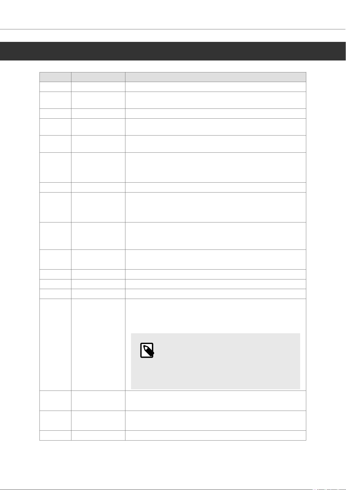
2.Release Notes
Version Release Description
5.16 April 2025 Added support for new platform.
5.15 December 2020 Added support for remotely run, stop and reset the PLC
application.
5.14 November 2018 Improved validation of driver settings.
5.13 July 2018 Corrected issue when importing tags with hexadecimal
addressing.
5.12 February 2018 Corrected issue when importing Melsoft Navigator files in import
module.
5.11 May 2017 Added support for GX Works 3 in import module.
Added support for new HMI platform.
Corrected issue when importing .asc files in import module
5.10 February 2017 Added support for FX5U controllers.
5.09 June 2016 Added support for new HMI models.
Corrected problem when adding tags with index addresses.
Corrected issue with manual redundant recovery.
5.08 November 2015 Added support for multiple CPU systems.
Added Timer coil, Accumulated timer coil and Counter coil
support.
5.07 October 2013 Corrected import of TIME data type.
Added Local UDP port setting.
5.06 September 2011 Support for GX Works 2 in import module.
5.05 April 2011 Added unicode string support for certain HMI models.
5.04 September 2010 Support for more HMI models.
5.03 February 2010 Support for addressing above 65535.
Added Ethernet redundancy.
Possible to address stations on MELSECNET.
NOTE
This driver requires that the Stations settings
are reconfigured. This is caused by the
added Ethernet redundancy and MELSECNET
functionality.
5.02 June 2009 Support for editable station numbers
Corrected Illegal station error using Indexed station
5.01 May 2009 Added support for more HMI models
Updated helpfile
5.00 April 2009 Initial version
2025-05 6 Beijer Electronics,
Page 7

Disclaimer
3.Disclaimer
Please note that changes in the controller protocol or hardware, which may interfere with the
functionality of this driver, may have occurred since this documentation was created. Therefore,
always test and verify the functionality of the application. To accommodate developments in the
controller protocol and hardware, drivers are continuously updated. Accordingly, always ensure that
the latest driver is used in the application.
Beijer Electronics, 7 2025-05
Page 8

Limitations
4.Limitations
No known limitations exist for the driver.
2025-05 8 Beijer Electronics,
Page 9
5.Connecting to the Controller
5.1.Ethernet
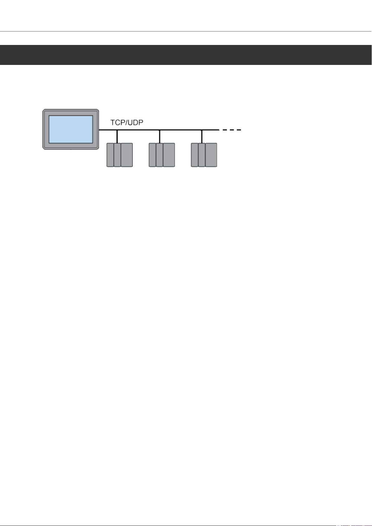
5.1.1.Ethernet Connection
Connection in a network is made according to Ethernet standards.
To extend the network a switch may be used.
5.1.2.Data Code
Connecting to the Controller
The driver supports binary code only.
5.1.3.E71 Module Connection Procedure
Settings in the E71 Module
The specified settings are applicable to both UDP and TCP communication protocols.
UDP communication supports multidrop and is faster than TCP. NOTE! Beijer Electronics recommend
using UDP.
When using UDP, the E71 Port Addr can be set to 5000 and then be independent of how the controller
program has opened the ports on the MELSEC QnA/Q E71 module. If UDP is used and the E71 Port
Addr is set to 5000, switch number 2 on the MELSEC QnA/Q E71 module must be turned off (= 0,
binary).
When using TCP, the E71 Port Addr must match the address given on the MELSEC QnA/Q E71 module
by the controller program.
Normally only the E71 TCP/IP Addr parameter needs to be changed.
For further information about settings in the controller, cable specifications and information about
connecting the controller to the HMI we refer to the manual for the current controller.
Beijer Electronics, 9 2025-05
Page 10
Settings
6.Settings
6.1.General
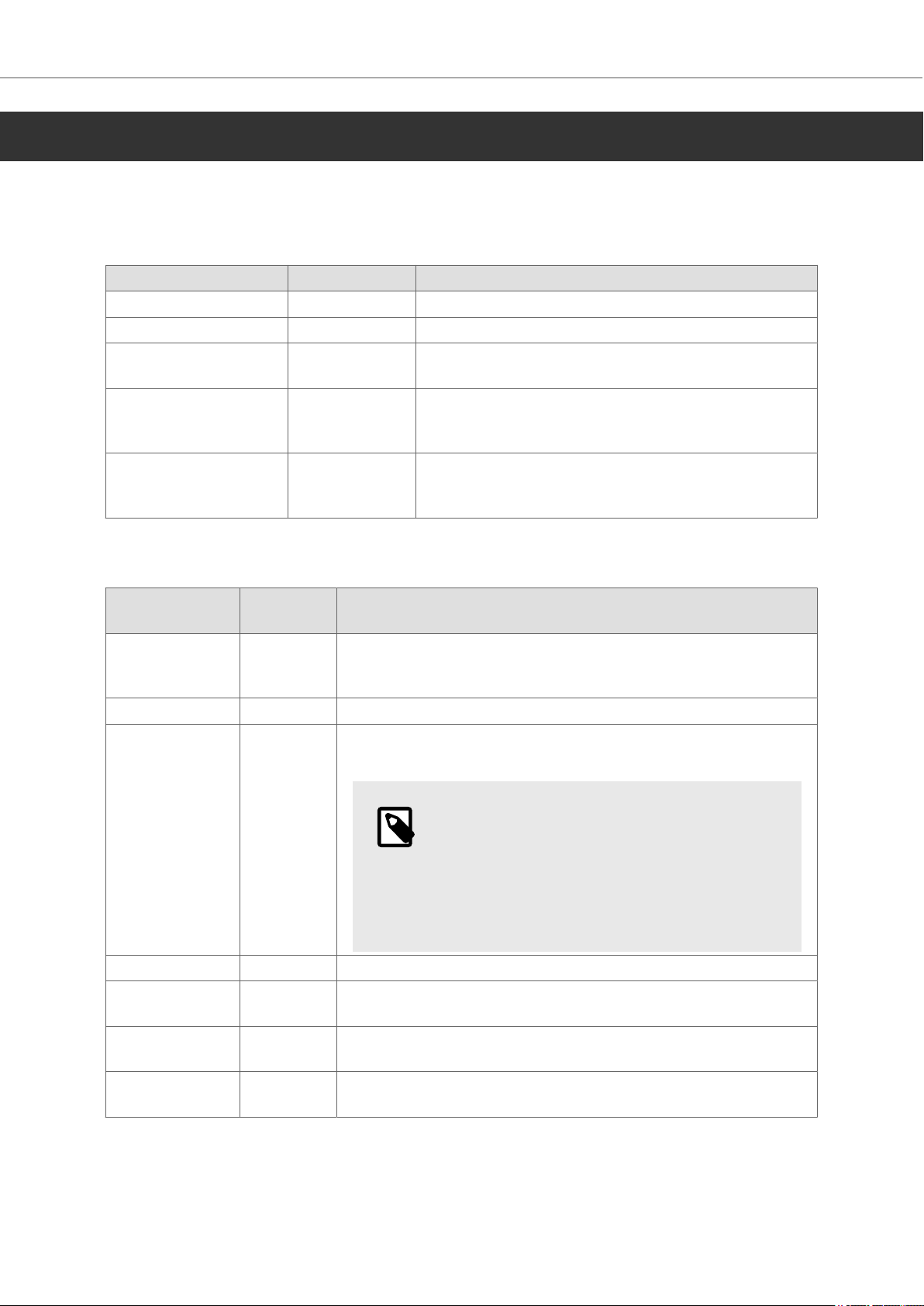
Under Settings the default station and communication mode are defined.
Parameter Default value Description
Default station 0 Station number of the default controller.
Communication mode UDP Select communication protocol (TCP or UDP).
Use MELSECNET Disable Activate columns in Stations settings to allow access
to specified Network and MNET.
X/Y addressing Hexadecimal Select if hexadecimal or octal addressing shall be
used for inputs and outputs (X/Y). Octal is normally
used for FX5U controllers.
Local UDP port 0 Local UDP port used by the driver. State 0 to use
a system assigned port number. This setting is only
relevant for UDP communication mode.
6.2.Advanced
Parameter Default
value
Enable
unicode
Byte order Intel Sets the byte order of the unicode character.
Timeout 400 The number of milliseconds of silence on the port before the
False Enables read/write of unicode characters to the controller.
Note that each character in a unicoded string will use two bytes
of the memory in the controller.
next retry is sent.
NOTE
Certain functions use the HMI as a
gateway for passing on communication.
These functions, including Transparent mode,
Routing, Passthrough mode, Modem, and
Tunneling, might need a higher timeout value.
Retries 3 Number of retries before a communication error is detected.
Offline station
retry time
Hide comm
error
Command line
options
10 How long to wait after a communication error before trying to
restore communication.
False Hides the error message that is displayed on communication
problem.
Special commands that can be passed to the driver. Available commands are described in the chapter Commands below.
Description
6.2.1.Commands
No commands are available for this driver.
2025-05 10 Beijer Electronics,
Page 11
6.3.Station
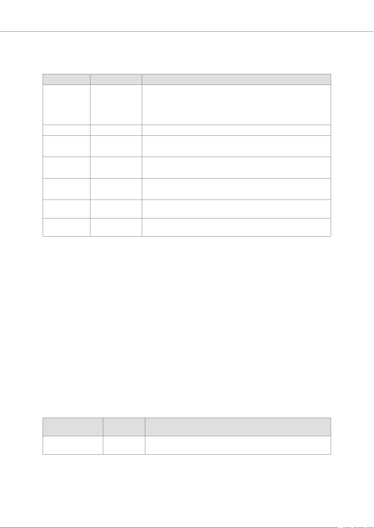
Under Stations the IP addresses and the port numbers for the different units are defined.
Parameter Default value Description
Station 0 The station number for the controller with the corresponding
IP address.
Maximum number of stations that can be configured: 20
Value range: [0-254]
IP Address 192.168.0.1 The IP address of the controller.
Port number 5000 The port number of the controller.
Value range: [0-65535]
Network 0 Network address when MELSECNET is activated.
Value range: [0-255]
MNET 255 MNET address when MELSECNET is activated.
Value range: [0-255]
CPU Control PLC Select which CPU that shall be addressed in a multiple CPU
system.
Red.station 0 The station number to the redundant station for the selected
station (see further description below).
Settings
6.3.1.Mixing MELSECNET and No MELSECNET Addressing
It is possible to address controllers both with MELSECNET addressing and without MELSECNET
addressing in the same list. Set Network to 0 and MNET to 255 for controllers that are not using
MELSECNET.
6.3.2.Configuring Redundant Stations
Configure the stations as normal, but in the Red.station column, add the station number to be used if
the connection to the selected station is lost. Entering the same value as in the Stations column will
disable the redundancy function.
Example:
Station 0 is the main station and station 1 is the redundant station.
In station 0 set Red.station = 1.
In station 1 set Red.station = 1 because redundant stations are not in use for this station.
6.4.Additional Functionality
6.4.1.Redundancy
Parameter Default
Enable
redundancy
False Enable the possibility to add redundant controllers in the
value
stations setting.
Description
Beijer Electronics, 11 2025-05
Page 12

Settings
Parameter Default
value
Automatic
redundant
recovery
Redundant
recovery time
When using manual recovery add the device x:REDUNDANT_RESET, where x is the main controller
station number.
True If true the driver tries to reconnect to the main controller
automatically when running on a redundant controller. If
not using automatic recovery use REDUNDANT_RESET to
manually reset communication to main controller.
10 The number of seconds the driver wait before trying to
reconnect to the main controller if running on redundant
controller. Only active if Automatic redundant recovery is
true.
Description
Example:
2:REDUNDANT_RESET is connected to the controller with station number 2 according to the station
settings. When this digital device is set the driver will try to reconnect to the main controller the
next time it sends a telegram.
2025-05 12 Beijer Electronics,
Page 13
7.Addressing
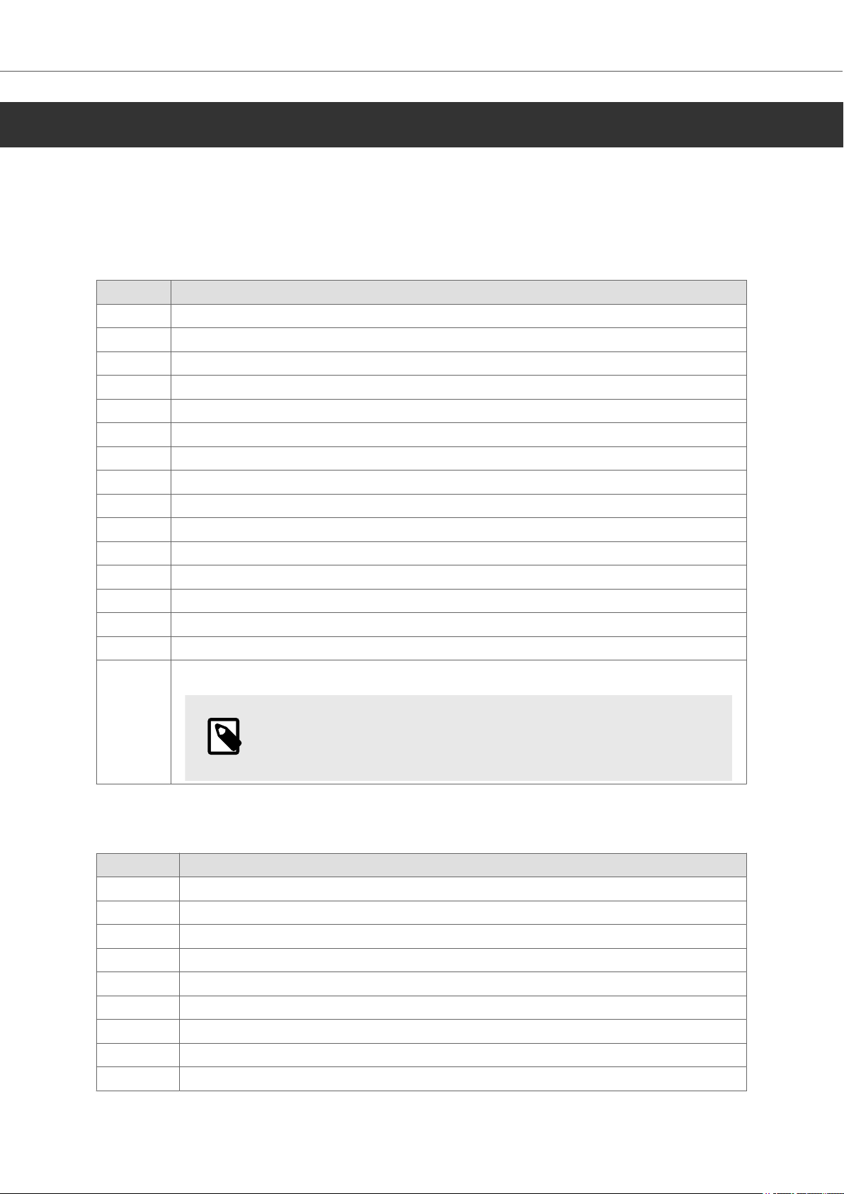
This driver supports Range based tag addressing.
The driver can handle the following data types in the controller:
7.1.Digital Signals
Type Comment
X Input Relay, hexadecimal addressing
Y Output Relay, hexadecimal addressing
B Link Relay, hexadecimal addressing
SB Link Special Relay, hexadecimal addressing
M Internal Relay, decimal addressing
SM Special Internal Relay, decimal addressing
L Latch Relay, decimal addressing
F Error Relay, decimal addressing
V Edge Relay, decimal addressing
S Step Relay, decimal addressing
TS Timer Contact, decimal addressing
STS Accumulated Timer Contact, decimal addressing
CS Counter Contact, decimal addressing
RUN Sends out a remote RUN command when set to 1, the value is then reset to 0.
STOP Sends out a remote STOP command when set to 1, the value is then reset to 0.
RESET Sends out a remote RESET command when set to 1, the value is then reset to 0.
Addressing
NOTE
The PLC needs to be in STOP mode before performing a RESET.
7.2.Analog Signals
Type Comment
T Timer, decimal addressing
ST Accumulated Timer, decimal addressing
C Counter, decimal addressing
D Data Register, decimal addressing
SD Special Register, decimal addressing
R File Register, decimal addressing
ZR Filer Register for addressing in one flow, decimal addressing
Z Index Register, decimal addressing
W Link Register, hexadecimal addressing
Beijer Electronics, 13 2025-05
Page 14

Addressing
Type Comment
SW Link Special Register, hexadecimal addressing
# Motion Register, decimal addressing
Bits in analog devices can be addressed as follows:
• D10.0 (least significant bit in D10)
• D20.F (most significant bit in D20)
The bit address is always given in hexadecimal format.
7.3.Station Addressing
The default station is the station that the HMI checks communication towards at start up, and it is
also the station used when no specific station is addressed. The default station is set in the settings
tab. For communication with other stations, the station number is given as a prefix to the device.
Example:
5:D0 means Data Register D0 in station 5.
7.3.1.Old MELSECNET Station Handling (Deprecated Functionality)
This functionality exists to support conversion from older drivers. It should not be used in new
projects since there is no guarantee it will be supported in the future.
It is possible to address a controller using a different Network and MNET that is not defined in the
Stations settings. This can be done with the following syntax:
<Station>:<Network>:<MNET>:<Tag>
Example:
1:2:3:D0 will address D0 in station 1, Network 2 and MNET 3.
To use the Network or MNET specified for the station an asterisk symbol (*) can be used.
Example:
1:*:3:D0
1:2:*:D0
1:*:*:D0
7.4.Performance
The following table shows the maximum number of signals per message for each address and type
of operation. For information how to optimize the project for best performance please see chapter
Efficient Communication.
Addresses Read Write Waste
D/SD/R/T/C/ST/Z/ZR/W/SW/# 480 480 20
M/SM/L/V/F/S/TS/STS/CS/TC/SC/CC 7680 1 100
X/Y/B/SB 864 1 16
RUN/STOP/RESET 1 1 1
2025-05 14 Beijer Electronics,
Page 15

8.Routing
The driver does not support any routing mode.
Routing
Beijer Electronics, 15 2025-05
Page 16
Import Module
9.Import Module
The import module is a component of the driver that enables automatic import and parsing of tag
definitions from a PLC project file or directly via communication with the PLC. Within iX Developer,
the driver uses the import module to retrieve tag names, data types, memory addresses, and
structured data types from the PLC. This facilitates seamless integration and mapping between the
PLC and the control or SCADA system, reducing manual configuration efforts and ensuring consistency
between engineering and runtime environments.
9.1.Driver-Specific Import Details
The import module makes it possible to import tags from GX IEC Developer and GX Works, both .csv
and .asc files can be imported. To use this feature, select MELSEC import format in the Import Tags
dialog.
For information on how to export files please see the documentation for the PLC programming tool.
General tag import steps
1. Open theTagsscreen in iX Developer.
2. Click the drop-down list by theImportbutton and selectImport tags to [controller
name].The[controller name]is the name given to the controller when created in iX Developer.
Default name is[Controller1].
3. Most drivers for iX Developer import their tags from a file. Select driver specific file on your
computer and clickImport.
4. The next dialog allows import of some or all of the tags selected from the import module. To
import all the tags, check theAll Itemscheckbox and clickOK. The selected tags will then
appear in the tags list and can be used as normal tags.
NOTE
When importing from GX Works 3 only Comments are imported, not Remarks.
Make sure the whole project is exported when importing tag lists that contains
structures.
NOTE
Importing tags is provided for your convenience. You can always manually enter tags
from within iX Developer. If you run into any issues with importing tags, simply
manually enter the tags within iX Developer.
It is generally recommended toimport only the tags, that will be usedfrom your
HMI to iX Developer. Importing all available tags from the import file may lead to
problems with iX Developer.
2025-05 16 Beijer Electronics,
Page 17
Efficient Communication
10.Efficient Communication
10.1.Packing of Signals
When tags are transferred between the driver and the controller, all tags are not transferred
simultaneously. Instead they are divided into messages with several tags in each message. By
decreasing the number of messages that have to be transferred, the communication speed can
improve. The number of tags in each message depends on the used driver.
NOTE
ASCII Strings and arrays are packed into one message for each object.
NOTE
Having different pollgroups will affect how requests are generated.
10.2.Waste
To make the message as efficient as possible, the waste between two tag addresses must be
considered. The waste is the maximum distance between two tag addresses that you can have and
keep them in the same message. The waste limit depend on the used driver.
NOTE
Waste is only valid for number-based addressing, not for Name-based addressing.
NOTE
Waste can only be calculated between two similar datatype tags, not between
different datatypes tags.
Scenario 1
When integer tags with address 4, 17, 45, 52 are used with waste limit of 20, this will end up creating
two messages.
First message with address 4 and 17 (tag address difference is 13 <= 20).
Second message with address 45 and 52 (tag address difference is 7 <= 20).
Reason: Difference between 17 and 45 is more than the waste limit of 20, hence creating 2nd
message.
Scenario 2
When integer tags with address 4, 17, 37, 52 are used with waste limit of 20, this will end up creating
one message.
Reason: Difference between the consecutive tags is less than or equal to the waste limit of 20, hence
creating one message.
Beijer Electronics, 17 2025-05
Page 18

Efficient Communication
Conclusion
Scenario 2 is more efficient than scenario 1.
2025-05 18 Beijer Electronics,
Page 19
Troubleshooting
11.Troubleshooting
11.1.Error Messages
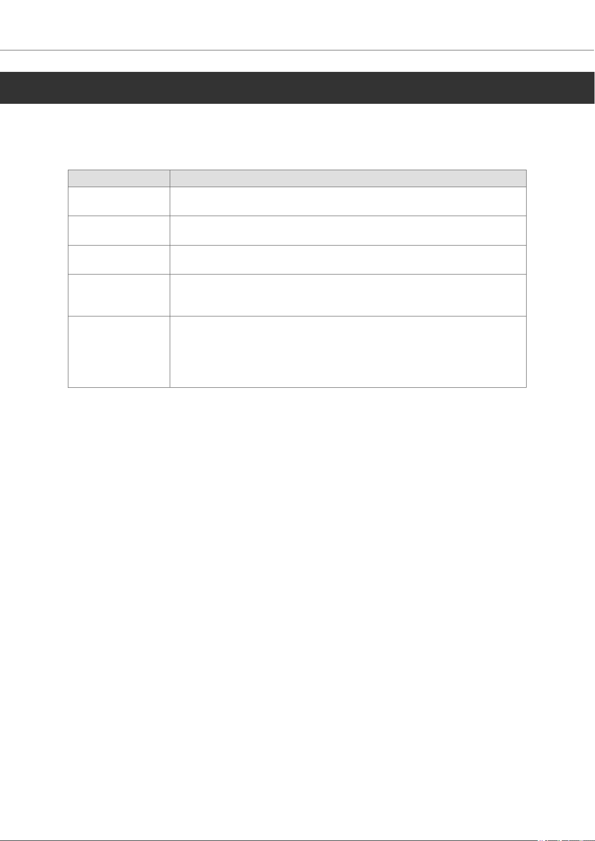
The meaning of error messages from the controller shown by the driver.
Error message Description
Comm Err Communication fails. Check communication settings, cable and station
number.
Illegal station The driver is trying to access an Ethernet station that is not defined in the
Stations configuration.
Error xxxx Stn n The error code xxxx was given from station n. See the controller
documentation for more information.
Out of range Stn n A read/write request exceeds the maximum address in station n. Verify
that all devices are within the valid address range for the connected
controller.
Bad Reply The driver received an unexpected response. Verify that the devices exist
and that their addresses are within a valid range for the connected
controller.
If a RUN/STOP/RESET operation is performed make sure the PLC accepts
remote operations.
Beijer Electronics, 19 2025-05
Page 20

20
 Loading...