

Page 1
User Manual
MULTIGATE PRO XR4400
Reference-Class 4-Channel Expander/Gate
Page 2

2 MULTIGATE PRO XR4400 User Manual
Table of Contents
Important Safety Instructions ...................................... 3
Legal Disclaimer ............................................................. 3
Limited warranty ............................................................ 3
1. Introduction ............................................................... 4
1.1 Technical background ....................................................... 4
2. The Design Concept ..................................................6
2.1 High quality components and design......................... 6
2.2 Inputs and outputs ............................................................ 6
3. Installation ................................................................. 6
3.1 Rack mounting ..................................................................... 6
3.2 Mains voltage ....................................................................... 6
3.3 Audio connections ............................................................. 6
4. Controls ...................................................................... 7
4.1 The front panel control elements ................................. 7
4.2 The rear panel elements .................................................. 8
5. Technical Background ............................................... 8
5.1 EXPANDER mode ................................................................ 8
5.2 Interactive control functions .......................................... 8
5.3 FLEXLINK function ............................................................ 10
5.4 The SIDECHAIN lter ........................................................ 10
6. Applications ............................................................. 10
6.1 Basic setting ........................................................................ 10
6.2 Proper positioning of microphones .......................... 11
6.3 Applications ...................................................................... 12
7. Specications ........................................................... 12
Page 3
3 MULTIGATE PRO XR4400 User Manual
9. Do not defeat the safety purpose of the polarized
TO BIND MUSICGROUP BY ANY EXPRESS OR IMPLIED
Important Safety Instructions
Terminals marked with this symbol carry
electrical current of su cient magnitude
to constitute risk of electric shock.
Use only high-quality professional speaker cables with
¼" TS or twist-locking plugs pre-installed. Allother
installation or modi cation should be performed only
by quali edpersonnel.
This symbol, wherever it appears,
alertsyou to the presence of uninsulated
dangerous voltage inside the
enclosure-voltage that may be su cient to constitute a
risk ofshock.
This symbol, wherever it appears,
alertsyou to important operating and
maintenance instructions in the
accompanying literature. Please read the manual.
Caution
To reduce the risk of electric shock, donot
remove the top cover (or the rear section).
No user serviceable parts inside. Refer servicing to
quali ed personnel.
Caution
To reduce the risk of re or electric shock,
do not expose this appliance to rain and
moisture. The apparatus shall not be exposed to dripping
or splashing liquids and no objects lled with liquids,
suchas vases, shall be placed on the apparatus.
Caution
These service instructions are for use
by quali ed service personnel only.
Toreduce the risk of electric shock do not perform any
servicing other than that contained in the operation
instructions. Repairs have to be performed by quali ed
servicepersonnel.
or grounding-type plug. A polarized plug has two blades
with one wider than the other. A grounding-type plug
has two blades and a third grounding prong. The wide
blade or the third prong are provided for your safety. Ifthe
provided plug does not t into your outlet, consult an
electrician for replacement of the obsolete outlet.
10. Protect the power cord from being walked on or
pinched particularly at plugs, convenience receptacles,
and the point where they exit from the apparatus.
11. Use only attachments/accessories speci ed by
themanufacturer.
12. Use only with the
cart, stand, tripod, bracket,
or table speci ed by the
manufacturer, orsold with
the apparatus. When a cart
is used, use caution when
moving the cart/apparatus
combination to avoid
injury from tip-over.
13. Unplug this apparatus during lightning storms or
when unused for long periods of time.
14. Refer all servicing to quali ed service personnel.
Servicing is required when the apparatus has been
damaged in any way, such as power supply cord or plug
is damaged, liquid has been spilled or objects have fallen
into the apparatus, the apparatus has been exposed
to rain or moisture, does not operate normally, or has
beendropped.
15. The apparatus shall be connected to a MAINS socket
outlet with a protective earthing connection.
16. Where the MAINS plug or an appliance coupler is
used as the disconnect device, the disconnect device shall
remain readily operable.
UNDERTAKING OR REPRESENTATION. THIS MANUAL
IS COPYRIGHTED. NO PART OF THIS MANUAL MAY
BE REPRODUCED OR TRANSMITTED IN ANY FORM
OR BY ANY MEANS, ELECTRONIC OR MECHANICAL,
INCLUDING PHOTOCOPYING AND RECORDING OF ANY
KIND, FOR ANY PURPOSE, WITHOUT THE EXPRESS
WRITTEN PERMISSION OF MUSICGROUPIPLTD.
ALL RIGHTS RESERVED.
© 2013 MUSICGroupIPLtd.
Trident Chambers, Wickhams Cay, P.O. Box 146,
Road Town, Tortola, British Virgin Islands
LIMITED WARRANTY
For the applicable warranty terms and conditions
and additional information regarding MUSIC Group’s
Limited Warranty, please see complete details online at
www.music-group.com/warranty.
1. Read these instructions.
2. Keep these instructions.
3. Heed all warnings.
4. Follow all instructions.
5. Do not use this apparatus near water.
6. Clean only with dry cloth.
7. Do not block any ventilation openings. Install in
accordance with the manufacturer’s instruc tions.
8. Do not install near any heat sources such as
radiators, heat registers, stoves, or other apparatus
(including ampli ers) that produce heat.
LEGAL DISCLAIMER
TECHNICAL SPECIFICATIONS AND APPEARANCES
ARE SUBJECT TO CHANGE WITHOUT NOTICE AND
ACCURACY IS NOT GUARANTEED. BEHRINGER,
KLARKTEKNIK, MIDAS, BUGERA, AND TURBOSOUND
ARE PART OF THE MUSIC GROUP MUSICGROUP.COM.
ALL TRADEMARKS ARE THE PROPERTY OF THEIR
RESPECTIVE OWNERS. MUSICGROUP ACCEPTS NO
LIABILITY FOR ANY LOSS WHICH MAY BE SUFFERED
BY ANY PERSON WHO RELIES EITHER WHOLLY OR
IN PART UPON ANY DESCRIPTION, PHOTOGRAPH
OR STATEMENT CONTAINED HEREIN. COLORS AND
SPECIFICATIONS MAY VARY FROM ACTUAL PRODUCT.
MUSIC GROUP PRODUCTS ARE SOLD THROUGH
AUTHORIZED FULLFILLERS AND RESELLERS ONLY.
FULLFILLERSAND RESELLERS ARE NOT AGENTS OF
MUSICGROUP AND HAVE ABSOLUTELY NO AUTHORITY
Page 4

4 MULTIGATE PRO XR4400 User Manual
1. Introduction
With the BEHRINGER MULTIGATE PRO you purchased a dynamics processor of the
high-end class designed to meet highest requirements: professionalrecording,
broadcast and television studios, CD and digital production facilities,
etc. Its complete range of features and innovative circuit topology make
the MULTIGATE PRO an all-purpose device for reducing noise in audio
recordings, forautomatically muting stage mics, expanding the dynamic
range of compressed recordings, improving the signal-to-noise ratio of noisy
communications systems and for producing special eects, etc.
Future-oriented BEHRINGER technology
Our MULTIGATE range of devices has been a hit ever since we introduced our rst
model several years ago. This expander/gate is based on many years of experience
and ndings in psychoacoustics and is used throughout the world in renowned
studios, sound reinforcement systems as well as in broadcast and television studios.
It was a real challenge to improve the well-known MULTIGATE even further,
and we are proud of our success. Compared to its predecessor models,
the MULTIGATE PRO not only has additional features, but also comes with
dramatically improved functionalities. For example, it now has a parametric lter
enabling you to accurately set the trigger frequencies, while the FlexLink system
allows for great exibility when linking the device’s individual channels in a
master/slaveconguration.
Basically, quadruple gates are not a new invention. However, packing four simple
noise gates into one enclosures usually means a compromise in terms of ease
of operation and func tionality. Too many control elements make such a device
impossible to handle, and if you sacrice crucial functions for the sake of easy
operation, the range of useful applications is restricted considerably.
The BEHRINGER MULTIGATE PRO is a quadruple expander/gate with a maximum
of functionalities and can still be operated conveniently. Interactive functions
make it easy and ecient to specically process any kind of program material,
while the need for “adjustment work” has been reduced drastically. Each of
the MULTIGATE PRO’s four sections comprises an ultra-fast gate, a programdependent expander, a lter section and high-precision meters indicating both
threshold point and gain reduction.
The IAC circuit (Interactive Attack Control)
One of the MULTIGATE PRO’s most outstanding features is the program-dependent
control of attack times. The new IAC circuit (Interactive Attack Control) analyzes
the program material to calculate the attack time by way of interac tion, so that the
hold/release process is triggered automatically depending on the program, which is
why the MULTIGATE PRO does not need a dedicated attack control.
Switchable gate/expander function
Another highlight of the MULTIGATE PRO is the switchable operating mode of
gate and expander. With the MODE func tion o, the MULTIGATE PRO works in
gate mode using an extremely fast attack time to gate all kinds of drum and
synthesizer sounds, without cutting their percussive edge.
In expander mode the device analyzes the shape and dynamic contents of
the input signal to calculate the control time parameters. It thus works as an
interactive expander that adapts automatically to the program signal. The result:
guitar sounds, vocals and complex mix signals can be “cleaned” without audible
clicks, breathing or other detrimental eects. Additionally, you can freely expand
any type of program material in its dynamic range.
Side-chain lter section
When several microphones are used, for example to pick up a drum set, crosstalk
between microphones can lead to unwanted triggering of the gate. The built-in
parametric sidechain lter of the MULTIGATE PRO allows the user to accurately
select the frequencies causing the trouble, so that the device responds to
these frequencies only. The monitor function can be used to pre-monitor the
lter, making it easier to adapt the circuitry to the acoustic proper ties of the
programmaterial.
FlexLink system
An innovative couple function gives you great exibility to synchronize the
expander/gate sections in a master/slave conguration.
◊ The following operational manual will introduce you to the BEHRINGER
MULTIGATE PRO and its various functions. After reading the manual
carefully, make sure it is always on hand for future reference.
1.1 Technical background
By employing current modern analog technology it is possible to manufacture
audio equipment with a dynamic range of up to 130 dB. In contrast to analog
techniques, the dynamic range of digital equipment is approximately 25dB
less. With conventional record and tape recorder technology, as well as
broadcasting, this value is further reduced. Generally, dynamic restrictions are
due to noisy storage in transmission media and also the maximum headroom of
thesesystems.
1.1.1 Noise as a physical phenomenon
All electrical components produce a certain level of inherent noise.
Currentowing through a conductor leads to uncontrolled random electron
movements. For statistical reasons, this produces frequencies within the
whole audio spectrum. If these currents are highly amplied, the result will be
perceived as noise. Since all frequencies are equally aected, we term this white
noise. It is fairly obvious that electronics cannot function without components.
Even if special low-noise components are used, a certain degree of basic noise
cannot be avoided.
This eect is similar when replaying a tape. The non-directional magnetic
particles passing the replay head can also cause uncontrolled currents and
voltages. The resulting sound of the various frequencies is heard as noise.
Even the best possible tape biasing can “only” provide signal-to-noise ratios of
about 70 dB, which is not acceptable today since the demands of listeners have
increased. Due to the laws of physics, improving the design of the magnetic
carrier is impossible using conventional means.
1.1.2 What are audio dynamics?
A remarkable feature of the human ear is that it can detect the most wide
ranging amplitude changes—from the slightest whisper to the deafening roar
of a jet-plane. If one tried to record or reproduce this wide spectrum of sound
with the help of ampliers, cassette recorders, records or even digital recorders
(CD, DAT etc.), one would immediately be restricted by the physical limitations of
electronic and acoustic sound reproduction technology.
The usable dynamic range of electro-acoustic equipment is limited as much
at the low end as at the high end. The thermal noise of the electrons in the
components results in an audible basic noise oor and thus represents the
bottom limit of the transmission range. The upper limit is determined by the
levels of the internal operating voltages; if they are exceeded, audible signal
distortion is the result. Although in theory, the usable dynamic range sits
between these two limits, it is considerably smaller in practice, since a certain
reserve must be maintained to avoid distortion of the audio signal if sudden level
peaks occur. Technically speaking, we refer to this reserve as “headroom”—
usually this is about 10 - 20 dB. A reduction of the operating level would allow for
greater headroom, i.e. the risk of signal distortion due to level peaks would be
reduced. However, at the same time, the basic noise oor of the program material
would be increased considerably.
Page 5
5 MULTIGATE PRO XR4400 User Manual
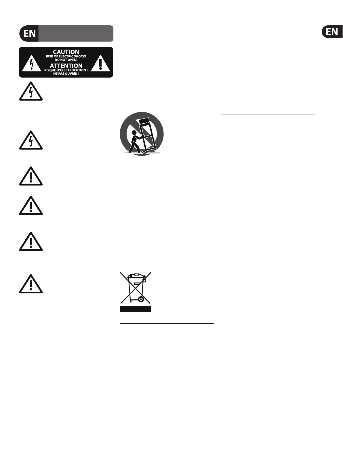
P/dB
140
120
100
80
60
40
Ear
Fig. 1.1: The dynamic range c apabilities of va rious devices
Microphone Amplifier
Power Amplifier
Tape Radio
Radio
Cassette
Recorder
It is therefore useful to keep the operating level as high as possible without
risking signal distortion in order to achieve optimum transmission quality.
It is possible to further improve the transmission quality by constantly
monitoring the program material with the aid of a volume fader, which manually
levels the material. During low passages the gain is increased, during loud
passages the gain is reduced. Of course it is fairly obvious that this kind of
manual control is rather restrictive; it is dicult to detect signal peaks and it is
almost impossible to level them out. Manual control is simply not fast enough
tobesatisfactory.
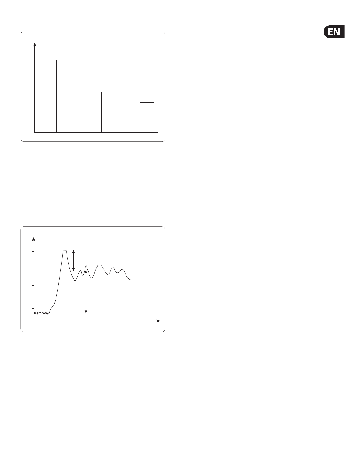
P/dB
+20
0
-20
-40
-60
-80
Fig. 1.2: The interactive relationship between the operating level and the headroom
Headroom
Effective SNR
Clipping
Operating level
Noise floor
t
The need therefore arises for a fast acting automatic gain control system
which will constantly monitor the signals and which will always adjust the
gain to maximize the signal-to-noise ratio without incurring signal distortion.
Thisdevice is called a compressor or limiter.
1.1.3 Compressors/Limiters
The principal function used in these devices is dependent on an automatic gain
control as mentioned in the previous section, which reduces the amplitude of
loud passages and therefore restricts the original dynamics to a desired range.
This application is particularly useful in microphone recording techniques,
tocompensate for level changes which are caused by varying microphone
distances. Although compressors and limiters perform similar tasks, oneessential
point makes them dierent: Limiters abruptly limit the signal above a certain
level, while compressors control the signal “gently” over a wider range.
Alimiter continuously monitors the signal and intervenes as soon as the level
exceeds a user-adjustable threshold. Any signal exceeding this threshold will be
immediately returned to the adjusted level.
A compressor also monitors the program material continuously and has a
certain threshold level. With compression, in contrast to the action of a limiter,
signalsare not reduced in level abruptly once the threshold has been exceeded,
but are returned to the threshold gradually. The signal is reduced in gain,
relativeto the amount the signal exceeds this point.
Generally, threshold levels for compressors are set below the normal operating
level to allow for the upper dynamics to be musically compressed. For limiters,
the threshold point is set above the normal operating level in order to provide
reliable signal limiting, to protect subsequent equipment from signal overload.
1.1.4 Expanders/Noise gates
Audio, in general, is only as good as the source from which it was
derived. Thedynamic range of signals will often be restricted by noise.
Synthesizers,eects devices, guitar pickups, ampliers etc. generally produce a
high level of noise, hum or other ambient background hiss, which can disturb the
quality of the program material.
Normally these noises are inaudible if the level of the desired signal lies
signicantly above the level of the noise. This perception by the ear is based on
the “masking” eect: noise will be masked and thus becomes inaudible as soon
as considerably louder sound signals in the same frequency band are added.
Nevertheless, the further the level that the desired signal decreases, the more
the noise oor becomes a disturbing factor. Expanders or noise gates oer a
solution for this problem: these devices attenuate signals when their amplitudes
drop, thereby fading out the background noise. Relying on this method,
gaincontrolling ampliers, like expanders, can extend the dynamic range of a
signal and are therefore the opposite of a compressor.
In practice, it is shown that an expansion over the entire dynamic range is not
desired. With an expansion ratio of 1:5 and a processed dynamic range of 30 dB,
an output dynamic range of 150 dB will be the result, exceeding all subsequent
signal processors, as well as human hearing. Therefore, the amplitude control is
restricted to signals whose levels are below a certain threshold. Signalsabove
this threshold pass through the unit unchanged. Due to the continuous
attenuation of the signals below this threshold, this kind of expansion is termed
“downward” expansion.
The noise gate is the simplest form of an expander: in contrast to the expander,
which continuously attenuates a signal below the threshold, the noise gate
cuts o the signal abruptly. In most applications this method is not very
useful, sincethe on/o transition is too drastic. The onset of a simple gate
function appears very obvious and unnatural. To achieve inaudible processing
of the program material, it is necessary to be able to control the signal’s
envelopeparameters.
By measuring the dynamic range of musical instruments in live recording
situations, you will nd that extreme amplitudes occur which often lead to
overload in subsequent signal processing equipment. Especially in broadcasting
and record cutting techniques, these signal peaks can lead to heavy distortion.
To avoid this kind of distortion or, for example, to avoid loudspeakers being
damaged by overload, Compressors or Limiters are used.
Page 6

6 MULTIGATE PRO XR4400 User Manual
2. The Design Concept
2.1 High quality components and design
The philosophy behind BEHRINGER products guarantees a no-compromise circuit
design and employs the best choice of components. The operational ampliers
NJM4580 which are used in the MULTIGATE PRO, are exceptional. They boast
extreme linearity and very low distortion characteristics. To complement this
design the choice of components includes high tolerance resistors and capacitors,
detent potentiometers and several other stringently selected elements.
For the rst time, the MULTIGATE PRO XR4400 uses SMD technology
(SurfaceMounted Device). These sub-miniature components known from
aerospace technology allow for an extreme packing density, plus the unit’s
reliability could be improved. Additionally, the unit is manufactured in
compliance with a ISO9000 certied management system.
2.2 Inputs and outputs
2.2.1 Balanced inputs and outputs
As standard, the BEHRINGER MULTIGATE PRO is installed with electronically
servo-balanced inputs and outputs. The new circuit design features automatic
hum and noise reduction for balanced signals and thus allows for trouble-free
operation, even at high operating levels. Externally induced mains hum etc.
willbe eectively suppressed. The automatic servo-function recognizes the
presence of unbalanced connectors and adjusts the nominal level internally to
avoid level dierences between the input and output signals (correc tion 6 dB).
◊ If the unit is damaged, please do not return it to us, but notify your
dealer and the shipping company immediately, otherwise claims for
damage or replacement may not be granted. Shipping claims must be
made by the consignee.
Please take the time to complete and return the warranty card within 14 days of
the date of purchase, otherwise you will lose the right to the extended warranty.
Or just use our online-registration (behringer.com).
3.1 Rack mounting
The BEHRINGER MULTIGATE PRO ts into one standard 19" rack unit of space
(1¾"). Please allow at least an additional 4" depth for the connectors on the
back panel. Be sure that there is enough air space around the unit for cooling
and please do not place the MULTIGATE PRO on high temperature devices such as
power ampliers etc. to avoid overheating.
3.2 Mains voltage
Before you connect your MULTIGATE PRO to the mains, please make
sure that your local voltage matches the voltage required by the
unit! Thefuse holder on the female mains connector has 3 triangular
markers, withtwo of these triangles opposing each other. YourMULTIGATE
RPO is set to the operating voltage printed next to these markers,
and can be set to another voltage by turning the fuse holder by 180°.
CAUTION:thisinstruc tiondoes not apply to export models exclusively
designed, e.g.for115Voperation!
3.3 Audio connections
3. Installation
Your BEHRINGER MULTIGATE PRO was carefully packed in the factory and
the packaging was designed to protect the unit from rough handling.
Nevertheless,we recommend that you carefully examine the packaging and its
contents for any signs of physical damage, which may have occurred in transit.
The audio inputs and outputs on the BEHRINGER MULTIGATE PRO are
fully balanced. If possible, connect the unit to other devices in a balanced
conguration to allow for maximum interference immunity.
◊ Please ensure that only qualified persons install and operate the
MULTIGATE PRO. During installation and operation the user must have
sufficient electrical contact to earth. Electrostatic charges might affect
the operation of the MULTIGATE PRO!
Output Cable Input
Pin 1
2 1
Pin 2 = (+) Signal
3
Pin 3 = (-) Signal
Fig. 3.1: Compensation of interference with balanced connections
Shield
(+) Signal + Hum
(-) Signal + Hum
RFI and Hum
1 2
3
Ground
Positive
Negative
(+)Hum + Signal
(-)Hum + Signal
2 x Signal
= Signal + 6 dB
Page 7

7 MULTIGATE PRO XR4400 User Manual
Fig. 4.1: MULTIGATE PRO front panel
Unbalanced ¼" TS connector
strain relief clamp
sleeve
tip
sleeve
(ground/shield)
tip
(signal)
Balanced ¼" TRS connector
strain relief clamp
sleeve
ring
tip
sleeve
ground/shield
ring
cold (-ve)
tip
hot (+ve)
For connection of balanced and unbalanced plugs,
ring and sleeve have to be bridged at the stereo plug.
4. Controls
The BEHRINGER MULTIGATE PRO has four channels. Each of these channels is
equipped with 3 or 4 push-buttons, 6 rotary controls and 11 LEDs.
4.1 The front panel control elements
(6)(4) (12)(11)
(1) (2) (3) (5) (7) (8) (9) (10)
Fig. 4.2: Cont rol elements on th e front panel
(1) The FREQUENCY control determines the lower limit frequency of the
sidechain lter, and covers a range from 100 Hz to 10 kHz.
(2) The BANDWIDTH control determines the slope or bandwidth of the
sidechain lter. The bandwidth can be set within a range from 2.3 to
0.7octaves, so as to realize even extremely narrow-band lter settings.
(3) The FILTE R control activates the parametric sidechain lter. To edit this lter
there you can use the frequency and BW control.
Balanced use with XLR connectors
12
3
input
1 = ground/shield
2 = hot (+ve)
3 = cold (-ve)
1
2
3
output
For unbalanced use, pin 1 and pin 3
have to be bridged
Fig. 3.2: Di erent plug type s
◊ Never use unbalanced XLR connections with microphone cables, as this
would short-circuit any phantom power transmitted over these cables!
(4) The MONITOR switch establishes a link between the sidechain control signal
and the audio output. As it also mutes the audio input signal the user can
pre-monitor the parametric lter output, which makes it easier to tune the
lter by ear.
◊ Please note that the MONITOR switch disables the channel’s audio signal.
(5) Use the THRESHOLD control to set the threshold point of the expander/
gate function within a range from BYPASS to +10 dBu. Signals below the
threshold are reduced in level. When the signal drops below the threshold,
the hold/release function starts reducing the signal to a level adjustable
with the RANGE/RATIO control.
◊ Please note that the MULTIGATE PRO enters bypass mode, when the
THRESHOLD control is set to its left stop position, i.e. all processing
functions are disabled and the signal is routed directly from the input
to the output.
(6) This “trac light” LED chain shows the current operating mode of the unit:
the “+” LED (red) indicates that the sidechain signal is below the threshold,
the HOLD LED (yellow) informs you that the hold circuit/release process has
been activated, while the “-” LED (green) shows that the sidechain signal is
above the threshold.
(7) The HOLD control determines the delay applied to the starting point of
the release process, af ter the signal has dropped below the threshold.
Thesetting range is 0 to 4 seconds.
Page 8

8 MULTIGATE PRO XR4400 User Manual
◊ The HOLD control is enabled in GATE mode only!
(8) The RELEASE control determines the time of the release process.
Thisprocess begins af ter the end of the hold phase and ends when the gain
reduction adjusted with the RANGE control is achieved. The setting range of
the RELEASE control is from 0.05 to 4 seconds.
◊ The RELEASE control is enabled in GATE mode only!
(9) The MODE switch is used to set the operating mode of the respective
channel. When the switch is out, the corresponding section works as an
ultra-fast gate. In this mode, even percussive signals can be processed
without any signal loss. With the MODE function on, the IRC expander
(Interactive Ratio Control) is activated. This interactive control function
allows for the program-dependent expansion of complex signals. Both the
attack time and the fade-out charac teristics (ratio) vary depending on the
program material. The agreeable results of this automatic process are less
critical adjustment work and “inaudible” expansion of the program material.
4.2 The rear panel elements
(13)
ALL INPUTS & OUTPU TS
FULLY BALANCED
BEHRINGER
MULTIGATE PRO
MODEL XR4400
CONCEIVED AND DESIGNED BY
BEHRINGER GERMANY.
MADE IN CHINA.
TIP/PIN 2
RING/PIN 3
SLEEVE/PIN 1
INPUTS 4OUTPUTS 4 0UTPUTS 3 INPUTS 3 0UTPUTS 2 INPUTS 2 0UTPUTS 1 INPUTS 1
ALL INPUTS & OUTPU TS
FULLY BALANCED
TIP/PIN 2
RING/PIN 3
SLEEVE/PIN 1
(10) The RANGE/RATIO control performs a dual function: depending on the
position of the MODE switch (i.e. depending on the operating mode of the
unit: gate or expander), the RANGE/RATIO control determines the maximum
amount of gain reduction or the expansion curve. In gate mode, this control
adjusts the RANGE determining the amount of maximum gain reduction
from 0 dB to -80 dB. In expander mode, it works as a RATIO control setting
the expansion ratio. The ratio function determines the input vs. output level
ratio, for all signals below the threshold. The setting range is from 1:1 to 1:4.
(11) The 8-digit GAIN REDUCTION meter informs you about the current amount
of gain reduction within a range from 1 to 40 dB.
(12) When you press the COUPLE switch, this channel is automatically congured
as a “slave” channel. Its left neighbor becomes the “master” now controlling
both channels in all their parameters.
ALL INPUTS & OUTPU TS
FULLY BALANCED
TIP/PIN 2
RING/PIN 3
SLEEVE/PIN 1
ALL INPUTS & OUTPU TS
FULLY BALANCED
TIP/PIN 2
RING/PIN 3
SLEEVE/PIN 1
(14)
(16) (15)
Fig. 4.3: Rear panel elements
(13) FUSE HOLDER / VOLTAGE SELECTOR. Please make sure that your local
voltage matches the voltage indicated on the unit, before you attempt to
connect and operate the MULTIGATE PRO. Blown fuses may only be replaced
by fuses of the same type and rating.
(14) MAINS CONNECTION. Use the enclosed power cord to connect the
unit to the mains. Please also note the instructions given in the
“Installation“chapter.
(15) AUDIO IN. These are the audio inputs of your MULTIGATE PRO, available both
as balanced 6.3 mm jack and XLR connec tors.
(16) AUDIO OUT. These are the audio outputs of your MULTIGATE PRO.
Matchingphone jack and XLR connectors are wired in parallel.
5. Technical Background
5.1 EXPANDER mode
As already described, a so-called downward expander automatically reduces
the overall level of all signals that drop below an adjustable threshold, and thus
expands the dynamic range of the program material. In other words, an expander
is the opposite of a compressor. Expanders usually work with a relatively at ratio
curve to fade out the signal smoothly.
Noise gates are a special form of expander using a much steeper ratio curve to
abruptly cut the signal when it drops below the threshold. As expanders and
gates are quite similar in what they do the following description of expanders
and their functionalities also applies to noise gates.
amplitude
max.
min.
0
amplitude
max.
min.
0
audio signal
masked noise audible noise
audio signal
masked noise audible noise
input
time
output
threshold
time
Fig. 6.1: Expander mo de
5.2 Interactive control functions
Like the COMPOSER, INTELLIGATE, MULTICOM, and others, the MULTIGATE PRO
uses the newly developed INTERACTIVE principle based on a chain of intelligent
control functions. For example, the IRC expander (Interactive Ratio Control)
doesnot use a xed ratio curve but varies this curve depending on the input level
and the setting of the THRESHOLD control.
Page 9

9 MULTIGATE PRO XR4400 User Manual
The following chapter describes the interactive control functions in full detail:
5. 2.1 THRESHOLD control
The THRESHOLD control determines the threshold point and disables the
respective channel. As it covers a very wide setting range it can be easily adapted
to any operating level:
Input levels above the adjusted threshold point pass the circuit unprocessed.
However, as soon as the input signal drops below the threshold, dynamics
processing sets on. Simple noise gates usually have a control to set the switch-on
and switch-o thresholds, but must perform their task without any dedicated
control elements that allow for varying the envelopes.
The BEHRINGER MULTIGATE PRO, however, is equipped with all necessary control
options. The following section makes clear why it is so important to be able to
adjust these parameters.
5.2.2 Attack, release and hold times
The BEHRINGER MULTIGATE PRO is equipped with a MODE switch as well as a
HOLD and RELEASE control to adjust the time-domain parameters that determine
the so-called envelope:
amplitude
attack hold release
Release time
Another important parameter is the release time, as it determines the time the
gate needs to reduce the signal level by a cer tain amount, after the signal has
dropped below the threshold.
Hold time
The hold-time parameter enables you to delay the starting point of the release
process. In particular, when processing frequently interrupted signals such as
vocals, an additional hold-time parameter is indispensable to prevent the gate
from switching o and back on during signal pauses.
5.2.3 IAC circuit (Interactive Attack Control)
The MULTIGATE PRO features an IAC circuit (Interactive Attack Control)
whichanalyzes the program material to calculate the attack time by way of
interaction, so that the hold/release process is triggered automatically depending
on the program material. This is the reason why the MULTIGATE PRO does not
need a dedicated attack control.
5.2.4 RANGE function
On the MULTIGATE PRO the dynamic processing is controlled by a high-grade
VCAwith a working range of more than 100 dB, i.e. the input signal can be
reduced in level by as much as 100 dB.
For most applications, however, it is neither desirable nor necessary to cut
the signal completely after it has dropped below the threshold. In particular,
whenprocessing signals with lots of background noise, this would result in
abrupt and audible control processes that are less likely to enhance the overall
sound quality.
max.
0
Fig. 6.2: Principle of envelope function
time
Attack time
The quality of an expander/gate is largely determined by the speed of its attack
function (rise time). This parameter denes the time the expander needs after
the signal has passed the threshold to recover from the applied gain reduction,
i.e. to reverse the control process.
Extremely short transients (level peaks) such as hand claps and percussive
instruments, etc. require an extremely short attack time to prevent the expander
from cutting the signal anks and thus deteriorating the sound.
The new BEHRINGER-developed UTR circuit (Ultra Transient Response)
incombination with a high-grade VCA allows for an extremely short response
time in gate mode, without audible switching noise as it is generated by many
conventional designs.
For this reason, the MULTIGATE PRO is equipped with a RANGE control that
allows you to limit the maximum gain reduction applied. Thus, you can use
smaller amounts of gain reduction making it possible to retain the natural sound
of the program material—in particular, with signals that contain plenty of
interferencenoise.
5.2.5 IRC circuit (Interactive Ratio Control)
In conventional expanders the control processes cut the signal abruptly below
the threshold, which usually leads to less satisfying results, because the onset
of the control function becomes audible. When inaudible expansion is needed,
itistherefore better to use a “soft-knee” characteristic around the threshold
point that allows for a smoother transition.
The BEHRINGER MULTIGATE PRO uses the newly developed IRC expander
(Interactive Ratio Control) whose attack time and ratio characteristics vary
automatically depending on the program material.
The IRC expander is switched on with the MODE switch. Low ratios and hence
subtle expansion produce a “smooth” transition, while higher ratios and heavy
expansion result in a “steeper” transition between the characteristic curves.
This so-called interactive, i.e. nonlinear IRC characteristic is perfectly adapted
to human hearing: critical wanted signals around the threshold point are less
expanded, while interference signals with lower levels (e.g. background noise)
are processed and faded out with a higher expansion ratio.
Page 10

10 MULTIGATE PRO XR4400 User Manual
output
gain 0 dB
threshold
IRC curve
expander. 1:8
noise gate, 1:∞
input
Fig. 6.3: IRC char acteristic c urve
The result is an expansion process that is less dicult to adjust and more tolerant
towards wanted signals whose levels are only slightly above the level of the
background noise.
5.4 The SIDECHAIN lter
Each channel has a parametric lter whose frequency and quality (bandwidth)
can be set precisely. This tunable lter allows you to select and fade out
specic frequencies that would otherwise lead to unwanted triggering of the
expandercircuit.
5. 4.1 The MONITOR function
This switch links the sidechain control signal with the audio output, while muting
the audio input signal, so that you can pre-monitor the lter output and tune the
parametric lter.
◊ Please note that the channel’s entire processing functions will be
disabled when you press the MONITOR switch.
6. Applications
This chapter describes a few typical applications of the BEHRINGER MULTIGATE
PRO. Starting from the basic setting shown below you can nd solutions to
most dynamics-based problems. Please take your time to study the following
application examples thoroughly, so as to be able to fully exploit the variety of
features your MULTIGATE PRO oers.
5.2.6 RATIO function
The ratio of the input-level-change vs. output-level-change after the onset of the
control process, i.e. after the signal has dropped below the threshold, is called
expansion ratio and can be set with the RATIO control. RATIO settings from 1:1.2
through 1:4 give you smooth and exactly dosed downward expansion.
The RATIO scale printed on the front panel indicates the expansion ratio in
decibels, i.e. it shows you the decibels by which the output signal is cut for each
reduction by one dB of the input signal.
With a 1:1 ratio the output signal level is the same as the input signal level,
i.e.there is no signal change. A ratio of 1:2 means that the output signal is
reduced by 2 dB when the input signal drops below the threshold by 1 dB.
Accordingly, with a ratio of 1:4, the output signal is cut in level by 4 dB when the
input signal is 1 dB below the threshold.
5.3 FLEXLINK function
The four channels of the MULTIGATE PRO can be operated both independently
of each other and in couple mode. In par ticular, when you record a choir it will
be useful to couple the individual microphone channels. For example, whenall
microphones are controlled by one singer, all vocals start and stop precisely
at the same point of time. Also when synchronizing several instruments,
inaccurateentries of individual musicians can be avoided.
To expand phase-coherent stereo signals (i.e. signals having the same phase),
it is imperative that the control processes be triggered simultaneously in both
channels. Due to the dierences in perceived loudness between the left and right
channels, unwanted shifts with reference to the stereo basis would be produced.
The innovative FlexLink function implemented in the MULTIGATE PRO allows for
a variety of couple options. For example, when you press the COUPLE switch of
channel 3, this channel is automatically congured as a “slave” channel, while its
neighbor—channel 2—becomes the “master” now controlling both channels in
all their parameters.
Activating the COUPLE switch automatically disables all controls and switches
of channel 3 (except for the MONITOR switch). Now, the controls of channel 2
take over full control of channel 3. Similar to a stereo fader, both channels work
in sync. To control channels 2 and 3 from channel 1, simply press the COUPLE
switches of channel 2 and 3.
Basically, the BEHRINGER MULTIGATE PRO can be used in three areas
ofapplication:
1. Eliminating interference noise and suppressing crosstalk in multi-channel or
multi-microphone congurations.
2. Expanding the dynamic range of compressed program material,
refreshingsampled sounds and creating special eects and sounds.
3. Using the MULTIGATE PRO as a de-esser and to specically eliminate
interference noise from recordings as well as to reduce the risk of feedback
in live situations.
6.1 Basic setting
Understandably, there is no standard setting that suits all kinds of applications.
Rather, the controls and switches must be set specically for the application
on hand. However, by studying the following practice-oriented descriptions
of typical applications you will soon develop a feel for how the various
functionswork:
6.1.1 The gate function
“Gating” is a so-called “high ratio” expander function and represents the
simplest function of the BEHRINGER MULTIGATE PRO. When the expander is
operated with maximum gain reduction (RANGE control fully to the left), it works
in “hard gating” mode. The gate function is used to automatically mute single
channels in multitrack mixdowns, stage microphones currently not in use and to
suppress background noise and crosstalk in multi-track recordings. In particular,
when processing percussive instrument the use of the “hard gating” function
isrecommended.
A few examples show you how to do it:
Electric signals from percussion instruments have a very short rise time. The time
between single hits on the instruments is normally lled up with noise produced
by adjacent instruments or room reverb, which makes it dicult or even
impossible to separate microphones acoustically. This unwanted crosstalk eect
can be accurately eliminated with the MULTIGATE PRO.
Page 11

11 MULTIGATE PRO XR4400 User Manual
Adjust all controls and switches to the following basic settings:
Control elements Position
MONITOR switch OUT
SC FILTER switch OUT
THRESHOLD switch fully clockwise
HOLD control center position
RELEASE control center position
MODE switch GAT E
RANGE/RATIO control fully counter-clockwise
Tab. 6.1: Initial se ttings of the MULTIGATE PRO
THRESHOLD control
Now turn the THRESHOLD control counter-clockwise until the lowest signal
delivered by the instrument you wish to record triggers the expander and is
reproduced without any sound deterioration. The “+” LED lights up as soon as
the expander is triggered. When everything’s set up properly, you will hear the
instrument clearly “stand out” against the overall sound image.
HOLD control (available in GATE mode only)
The program material (e.g. speech/vocal recordings) often contains many and
sometimes very short signal pauses, which could switch the gate o and back on
over and again. The hold function prevents this annoying “utter” eect known
from conventional designs, simply by delaying the starting point of the release
process. Thus, the gate remains on during short signal pauses. When the adjusted
hold time has expired, the gate closes the audio channel depending on how the
release function has been set.
◊ Please note that this control can be used in gate mode only!
RELEASE control (available in GATE mode only)
Many percussion instruments have long decay times (e.g. cymbals). As the release
time can be adjusted on the MULTIGATE PRO, the device allows you to follow the
decay curve of the instrument so that its overall sound character will be retained.
In this way, you can avoid that short release times aect the natural decay phase
of the instrument or its corresponding reverb ambiance.
Slowly decaying or heavily reverberated signals are best processed with long
release times. You will note that with most drum sounds a short release time
should be used for the sake of acoustic separation, while longer release times are
usually better for cymbals and tom-toms.
Once all control elements have been set properly, your percussion sounds will be
“dry”, “powerful” and acoustically well-dened.
◊ Please note that this control can be used in gate mode only!
6.1.2 The expander function
In contrast to the gate function, the expander triggers a continuous attenuation
of the signal, as soon as it has dropped below the threshold.
RATIO control
With the MODE switch in, the MULTIGATE PRO works as an interactive expander.
The RATIO control determines the expansion curve. For example, when a piece
of music was highly compressed during the recording session, the lost dynamics
can be restored through complementary expansion. With a bit of feeling you
can set the following controls by ear so that the original dynamics (prior to the
compression process) will be restored.
We recommend that you set the RATIO control to about 1:1.2 through 1:2 to allow
for a “smooth” expansion cur ve, and that you adjust the THRESHOLD control so
that the entire dynamic range of the music piece will be below the threshold
point. Now set the THRESHOLD control so that only the loudest passages of the
program material surpass the threshold point (“-” LED ashes). In the same way,
you can articially expand the dynamic range of any instrument. Inparticular,
when processing sampled sounds, expansion can produce nice results,
becausesamplers usually have a highly limited dynamic range. When processing
percussion sounds (e.g. snare drum) you can use downward expansion to create
interesting eects, for example, by setting the threshold to about mid-position,
so that only the “lower” part of the dynamics will be processed: the signal decays
unchanged until the adjusted threshold is reached, and any subsequent signal
portions are faded out with increasing at tenuation.
6.2 Proper positioning of microphones
The main task of an expander is to separate unwanted background noise from the
actual signal and to eliminate this noise “inaudibly”. Understandably, there must
be a minimum dierence in the levels of wanted signal and interference signal,
so as to be able to dene a threshold point for the expander.
However, the optimum operation of an expander depends on the proper choice
and positioning of the microphones:
Be extremely careful when instruments with high-frequency portions are played
to the sides or back of a microphone with a cardioid polar pattern. Most room
microphones suer from a deterioration of their directivity when picking up
high frequencies. For example, with a sensitivity dierence of not more than
2-3dB around 5-10 kHz between the main and lateral axes, cymbals can produce
enormous crosstalk in tom-tom microphones, or the hi-hats can mask the sound
of the snare drum.
You should make optimum use of the specic directivity of a microphone to
acoustically separate other instruments as perfectly as possible. Do as best as
you can to separate the sound sources acoustically simply by positioning the
microphones correctly.
RANGE control
The RANGE control determines the amount of maximum attenuation of the
audio signal. When you process instruments with long decay times, it will
be helpful to set the RANGE control to mid-travel position, so that the signal
will not be suppressed completely. Although the MULTIGATE PRO allows for a
maximum gain reduction of 80 dB, it is usually not useful to reduce the signal
level by this maximum amount. In par ticular, with highly noise-aected signals
we recommend that you use a signal attenuation of not more than 10 to 20 dB,
sothat the onset of the gate function will not become too obvious.
Yet, in some applications even perfectly positioned microphones might
not produce satisf ying results. With its side-chain function the BEHRINGER
MULTIGATE PRO gives you the option of frequency-selective expansion and thus
another aid to ensure perfect acoustic separation of the sound sources.
Page 12

12 MULTIGATE PRO XR4400 User Manual
6.3 Applications
6.3 .1 Suppressing crosstalk in multi-track applications
One of the most frequent applications of an expander/gate is the elimination
of unwanted crosstalk between single channels during recording or playback.
In particular, when recording acoustic drum sounds, this type of application is
frequently used, because here several microphones closely positioned next to
each other are used.
The high sound pressure levels of the individual instruments lead to crosstalk
in adjacent microphones. Frequency cancellations and a non-dened sound
(“comblter” eect) are the result. It has proven wise to use a separate
microphone for each drum instrument and to “gate” each microphone channel.
Insert the BEHRINGER MULTIGATE PRO into the recording channel of the snare
drum, for example, and adjust the device so that it responds only to hits on the
snare drum. Each single microphone should be optimally positioned before,
andthe threshold of the respective channel should be set so that the drum sound
can be separated cleanly, just as if the instrument were played alone.
6.3.2 Reducing crosstalk in stage microphones
The MULTIGATE PRO can be used in a variety of live/stage and multimicrophone
applications: a moderately set expander can eectively suppress background
noise, or the noise build-up that is typically produced by compressors as well
as crosstalk between microphones, etc. without causing other unwanted
sideeects.
7. Specications
Audio Input
Connectors XLR and ¼" jack
Type RF ltered, servo-balanced input
Impedance 50 kOhm balanced, 25 kOhm unbalanced
Max. Input Level +21 dBu balanced and unbalanced
CMRR typ. 40 dB, >55 dB @ 1 kHz
Audio Output
Connectors XLR and ¼" jack
Type Electronically servo-balanced output stage
Impedance 60 Ohms balanced, 30 Ohm unbalanced
Max. Output Level +21 dBu, +20 dBm balanced and
unbalanced
System Specications
Frequency Response 18 Hz to 30 kHz, +/- 3 dB
Noise >95 dBu, unweighted, 22 Hz to 22 kHz
Typically, an expander can be used to process vocal tracks. Particularly when
using a compressor, the distance between singer and microphone is of crucial
importance: As the distance increases, more and more disturbing background
noise is picked up. You should therefore use the expander function to fade out
unwanted interference noise “inaudibly” during signal pauses.
In live situations you can eliminate bleeding, for instance, from drum to piano
tracks, or clean your recordings from other acoustic “pollution”.
If you do not have enough microphones (or MULTIGATE PRO!) to record each
instrument separately, try forming so-called subgroups: comprise the snare and
middle toms, side toms, kick drum and cymbals in one group using the subgroup
facilities on your mixing console.
The goal is to position the group’s microphones and to adjust the expander
so that with each hit on a specic instrument only one microphone opens,
thustransmitting only one specic instrument, while the remaining microphones
remain muted.
6.3.3 Reducing feedback in stage microphones
As soon as a singer sings into his/her microphone, background noise is masked
and thus not perceived. During signal pauses, however, the microphone picks
up the noise from PA and monitor speakers, which can lead to torturing feedback.
By inserting the MULTIGATE PRO into the vocal channel and by adjusting it to
mute the microphone when it is not in use, you can reduce the risk of feedback in
this particular channel.
Basically, this conguration should be used for all stage microphones.
THD 0.008% typ. @ +4 dBu, 1 kHz, Gain 1
IMD 0.01% typ. SMPTE
Crosstalk <-100 dB, 22 Hz to 22 kHz
Gate Section
Type UTR (Ultra Transient Response) gate
Threshold variable (BYPASS to +10 dBu)
Attack program dependent
Hold variable (0 to 4 sec)
Release variable (50 ms to 4 sec)
Range variable (0 to -80 dB)
Expander Section
Type IRC (Interactive Ratio Control) expander
Attack program dependent
Ratio variable (1:1 to 1:4)
Side-Chain Filter
Frequency variable (100 Hz to 10 kHz)
BW (Bandwidth) variable (2.3 to 0.7 oct.)
Page 13

13 MULTIGATE PRO XR4400 User Manual
Function Switches
Monitor monitors the side-chain key signal
Filter activates the side-chain lter
Mode gate/expander switch
Couple activates the FlexLink function
Indicators
“+” indicator signal is below threshold
“Hold” indicator signal reaches the threshold
“-” indicator signal is above threshold
Gain Reduction 8-segment LED display:
1/3/6/10/15/20/30/40 dB
LED indicator for each function switch
Power Supply
Mains Voltages
USA/Canada 120 V~, 60 Hz
U.K./Australia 240 V~, 50 Hz
Europe 230 V~, 50 Hz
General Export Model 100 - 120 V~, 200 - 240 V~, 50 - 60 Hz
Power Consumption max. 20 Watts
Fuse 100 - 120 V~: T 630 mA H
200 - 240 V~: T 315 mA H
Mains Connection Standard IEC receptacle
Physical
Dimension 44.5 x 483 x 217 mm (1 ¾ x 19 x 8 ½")
Net Weight approx. 2.2 kg (approx. 4.8 lbs)
Shipping Weight approx. 3.5 kg (approx. 7.7 lbs)
BEHRINGER i s constantly str iving to maintain the h ighest profes sional standards. A s a result of these e ffort s,
modific ations may be made f rom time to time to exi sting product s without prio r notice. Specif ications and
appearance m ay differ fro m those listed or sho wn.
Page 14

We Hear You
 Loading...