

Page 1

Synthesizers and Samplers
MODEL D
Authentic Analog Synthesizer with 3 VCOs,
Ladder Filter, LFO and Eurorack Format
User Support Bulletin
Introduction
The unit is carefully calibrated at the factory. The performance may change over time or due to environmental changes,
and the following recalibration procedures will help bring it back to its factory settings. If you do not feel comfortable doing
these calibrations, then we recommend they are done by an experienced audio service technician. This is especially true for
those units that need to be opened to gain access to voltage test points and calibration potentiometers.
CAUTION: Incorrect calibration or damage to the delicate adjustment potentiometers may lead to the unit
becoming inoperable.
Note: Although re-calibration will not invalidate the warranty, any damage caused during re-calibration may invalidate
the warranty.
Equipment required
1. Small insulated trimpot screwdriver
2. Small Phillips screwdriver
3. A at sheet of cardboard or other insulator as wide as the MODEL D. (This will help prevent damage to the top panel when it is
inverted and resting on the bottom chassis)
The following equipment is required for the Oscillator adjustment and Octave Range adjustment:
1. An external MIDI keyboard of at least 3 octaves including A2 and C6
2. MIDI cable
3. Pair of headphones or a sound system to monitor the main output
The following equipment is required for the Pitch CV adjustment:
1. Digital DC Voltmeter with a scale that can display accurately to 0.001 V
2. Laptop or desktop computer previously loaded with and running a MIDI utility that can send SysEx commands
to the MODEL D
3. USB type A to USB type B connection cable
985-40000-01103 Rev.A
2021-02-03
Condential, for internal use only. Not to be reproduced.
page 1 of 23
Page 2

Synthesizers and Samplers
MODEL D
A-440 Reference
The MODEL D A-440 pitch is generated and regulated by the MCU and there is no adjustment required. This set frequency is
used as a reference in the following procedure to calibrate OSC1.
Important Note about Reset
If you have previously adjusted the MIDI IN Transpose or MIDI Note Zero Volts, you MUST reset the MODEL D to its factory
settings before doing the following procedures.
Preparation
Before doing the PITCH CV calibrations, become familiar with, and practice the procedures for sending SysEx
commands to the MODEL D. In this way, you will spend less time with the calibrations.
Calibration Procedure
The main printed circuit board (PCB) of the MODEL D has various test points and miniature potentiometers (trimpots) that allow
the various calibration and adjustment procedures to be carried out. This involves lifting up the front panel to allow access to the
bottom side of the PCB.
Three main calibrations can be carried out:
1. The PITCH CV can be calibrated using a computer to send a SysEx command, an external keyboard, and a digital DC voltmeter.
See PITCH CV Calibration.
2. The oscillators can be calibrated using a guitar tuner or the internally-generated A-440 concert pitch, and an external
keyboard. See Oscillator Calibration.
3. The Octave RANGE can be calibrated using an external keyboard. See Octave Range Calibration.
page 2 of 23page 2 of 23
Page 3

Synthesizers and Samplers
*Headphones
Power
Adapter
MOTŌR49 MIDI Keyboard/Controller
MIDI OUT
*Active Loudspeaker
*Use Headphones or a Loudspeaker
to listen to the output during
the Oscillator calibration
MIDI IN
Laptop or desktop computer
running a MIDI Utility
to send SysEx messages
(for PITCH CV calibration)
USB B
USB A
MODEL D
Preliminary Procedure
Follow all steps in the order in which they are presented.
The diagram below shows the typical connections for this procedure.
Connections
Connect the external power supply adapter to the rear power input of the MODEL D.
Connect the MIDI output of an external keyboard to the MIDI IN connector of the MODEL D.
Connect a laptop or desktop computer to the MODEL D USB input. (This is only required if you are doing the
PITCH CV calibration, or doing a Reset.)
page 3 of 23page 3 of 23
Page 4

Synthesizers and Samplers
KNOBS
TUNE 0
GLIDE 0
MOD MIX *
MOD DEPTH 0
LFO RATE 0
SWITCHES
OSC3/FILTER EG *
NOISE/LFO *
SQR/TRNG *
* NO PREFERENCE
KNOBS
OSC1 RANGE 8’
OSC2 RANGE 8’
OSC3 RANGE 8’
OSC1 WAVEFORM SAWTOOTH
OSC2 WAVEFORM SAWTOOTH
OSC3 WAVEFORM SAWTOOTH
OSC2 TUNE 0
OSC3 TUNE 0
SWITCHES
OSCILLATOR MOD OFF
OSC3 CONTROL ON
KNOBS
OSC1 VOLUME 10
OSC2 VOLUME 10
OSC3 VOLUME 10
EXT IN VOLUME 0
NOISE VOLUME 0
OSC1 SELECT ON
OSC2 SELECT OFF
OSC3 SELECT OFF
EXT IN SELECT OFF
NOISE SELECT OFF
SWITCHES
WHITE/PINK *
KNOBS
MAIN VOLUME *
PHONES VOLUME *
SWITCHES
MAIN OUT *
A-440 ON
* VOLUME AS NEEDED
KNOBS
CUTOFF FREQ 5
FILTER EMPHASIS 0
AMOUNT CONTOUR 0
FILTER ATTACK 0
FILTER DECAY 0
FILTER SUSTAIN 0
LOUDNESS ATTACK 0
LOUDNESS DECAY SEC
LOUDNESS SUSTAIN 10
SWITCHES
FILTER MODE LO
FLTR MODULATION OFF
KEYBRD CONTROL1 OFF
KEYBRD CONTROL2 OFF
FILTER DECAY OFF
LOUD DECAY OFF
EXTERNAL KEYBOARD
MOD WHEEL DOWN
PITCH WHEEL CENTERED
MODEL D
Turn down the MODEL D headphone volume knob, and connect your headphones to the MODEL D headphones
output connector. Alternatively, you can monitor the MODEL D output using the main outputs and a suitable sound
system and speakers.
Turn on the MODEL D rear panel power switch and check that its Power LED comes on.
Important: Leave the MODEL D turned on for approximately 30 minutes. This will allow the circuits time to warm up
and the components and performance to stabilise with temperature. Without this warm-up time, the calibrations will
be inaccurate.
Set the MODEL D controls as shown below.
MODEL D Control Settings for Calibration
Lifting o the top panel
Turn o the MODEL D power.
Try and do the following steps quickly and carefully to keep any cooling down to a minimum.
page 4 of 23page 4 of 23
Page 5
Synthesizers and Samplers
Take care not to
pull on these cables
MODEL D
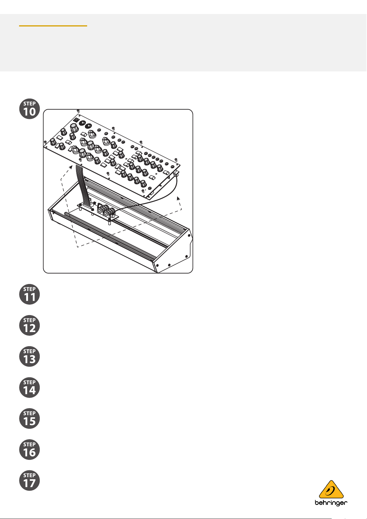
Carefully undo the 8 screws on the top panel as shown. There is no need to undo any other screws.
Carefully lift the top panel assembly and turn it over so the PCB is facing upwards. Be careful not to pull on the two
cables from the lower side of the main PCB. As your connections to other equipment are still in place, take care not to
pull out any cables or damage them.
Place a piece of cardboard or similar insulator between the controls and the main chassis. This will help prevent
damage to the controls as you lay the top assembly onto the main chassis. To protect the wooden side panels from
being scratched, you can add some protective tape over the top edge of each side panel.
Make sure that the top panel is in a secure position and that it is not liable to be dropped or damaged, or become
disconnected with its internal cables or the MIDI cables or headphone cable.
Double check that the MODEL D controls are still as shown on the previous page, in case they were moved during the
top panel removal.
Because the main PCB is exposed, make sure you are not touching it, and that it is not touching any metal work that
may cause a short-circuit.
Turn on the MODEL D rear panel power switch and check that its Power LED comes on.
Do not turn o the MODEL D or let it cool down, until all the calibrations are completed.
page 5 of 23page 5 of 23
Page 6

Synthesizers and Samplers
DC Voltmeter
Voltmeter
0.001
MODEL D
If the A-440 switch is in the ON position, you should hear the tone in your heaphones or main system if you carefully
bring the headphone volume or main volume up.
Now that everything is ready, inspect the bottom surface of the PCB as shown on the next page.
The diagram below shows the Test Points TP1 and TP2 used in the PITCH/CV calibration. Take a look at the PCB and locate these
two test points.
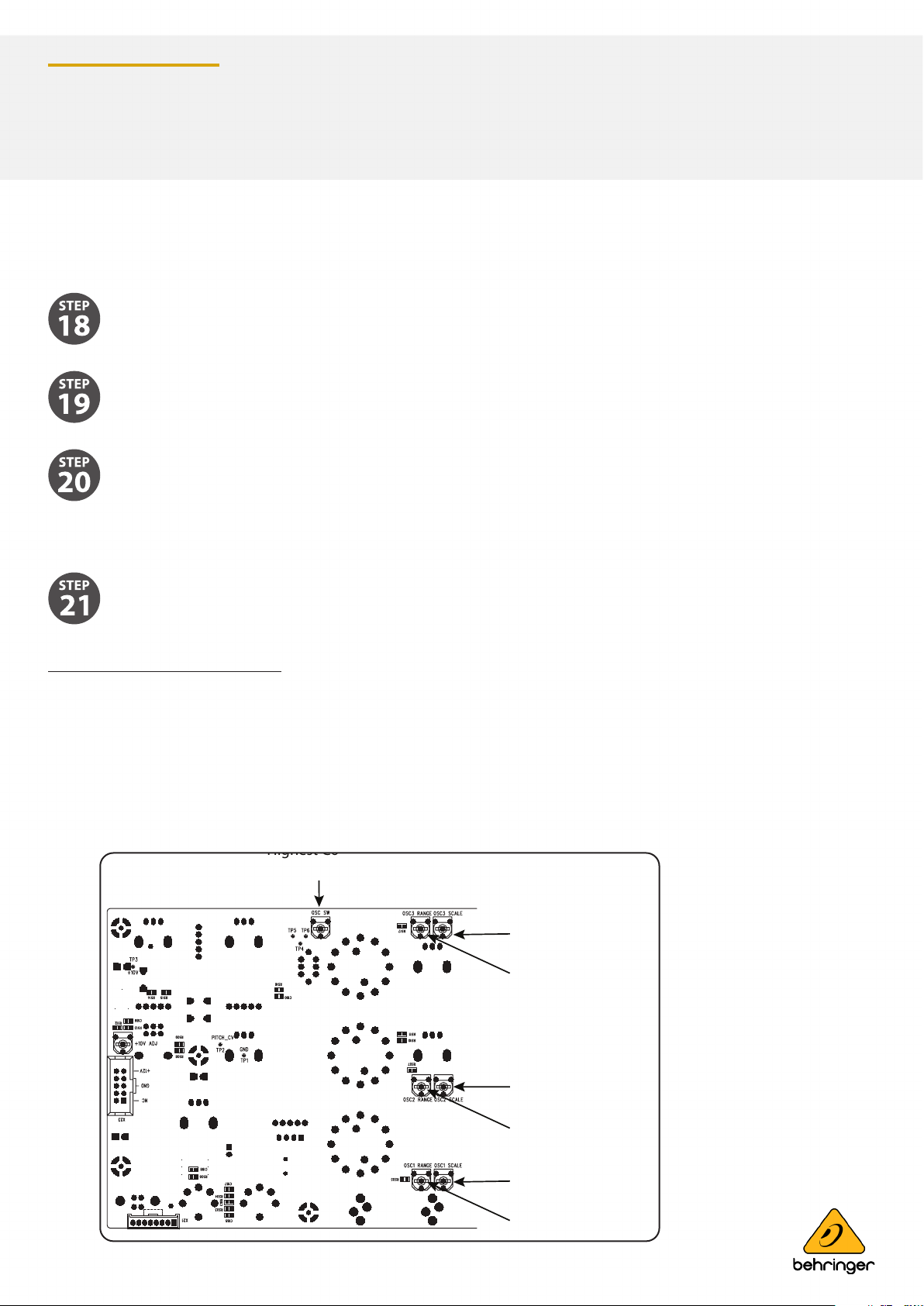
The diagram below shows the adjustment trimpots that are used in the Oscillator and Octave range calibration procedures. Take
a look at your PCB and locate these various trimpots. (The later version of the PCB uses dierent multi-turn trimpots.
page 6 of 23page 6 of 23
Page 7

Synthesizers and Samplers
OSC3 Scale Adjustment
OSC3 Range Adjustment
Octave Adjustment
OSC1 Scale Adjustment
OSC1 Range Adjustment
OSC2 Range Adjustment
OSC2 Scale Adjustment
Highest A5
Lowest A2
Highest C6
MODEL D
PITCH CV Calibration
The PITCH CV calibration procedure uses a computer MIDI utility to send a SysEx command to the MODEL D to put it into
calibration mode.
Once in calibration mode, a digital DC Voltmeter is used to measure the voltage at a test point while test notes are played using
the external keyboard.
The meter should have a resolution of 3 or more decimal places, for example 0.001 V.
page 7 of 23page 7 of 23
Page 8
Synthesizers and Samplers
MODEL D
Putting the MODEL D into Pitch CV Calibration Mode
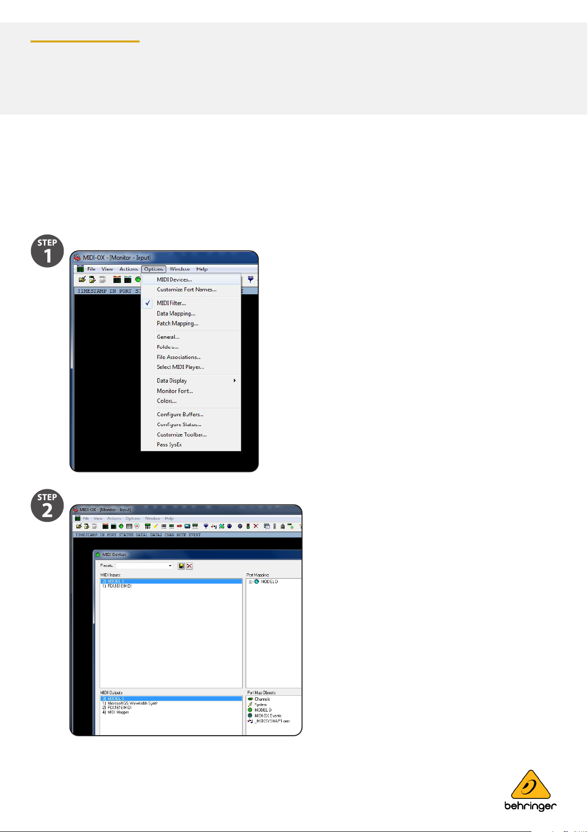
The following example shows the use of the popular MIDI Utility “MIDI OX” to send a SysEx message from your computer to
the MODEL D to put it into PITCH CV Calibration mode. (This same procedure can be used to send any SysEx message to the
MODEL D.)
Run MIDI OX on your computer, and go to OPTIONS/MIDI DEVICES.
Select the MODEL D as the MIDI IN and MIDI OUT.
page 8 of 23page 8 of 23
Page 9
Synthesizers and Samplers
MODEL D
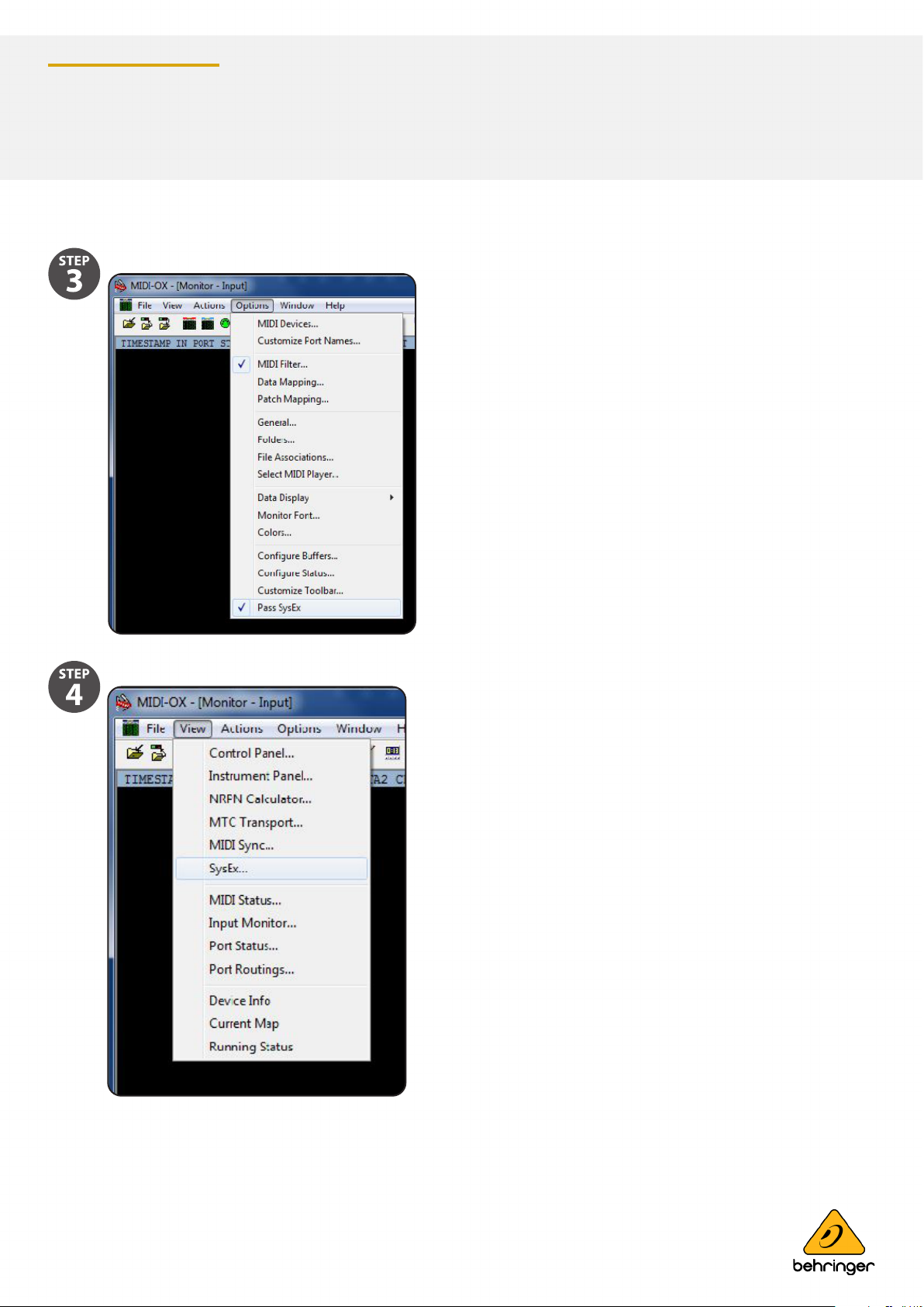
Select "Pass SysEx" at the bottom of the Options pull down menu. (It might already be ticked, which is ne.)
In the VIEW Menu, select SysEx..
page 9 of 23page 9 of 23
Page 10
Synthesizers and Samplers
MODEL D
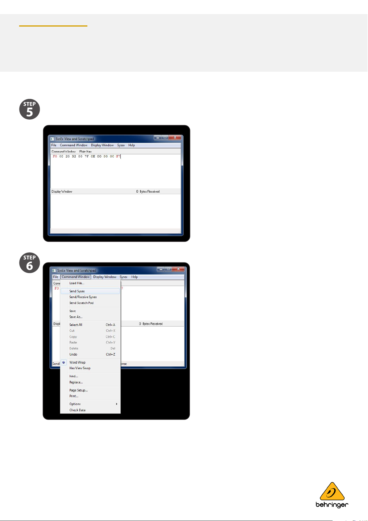
In the Command Window, enter the SysEx command to be sent to the MODEL D. For PITCH Calibration, the
command is:
F0 00 20 32 00 7F 0E 00 00 00 F7
In the Command Window drop-down menu, select Send SysEx.
page 10 of 23page 10 of 23
Page 11
Synthesizers and Samplers
MODEL D
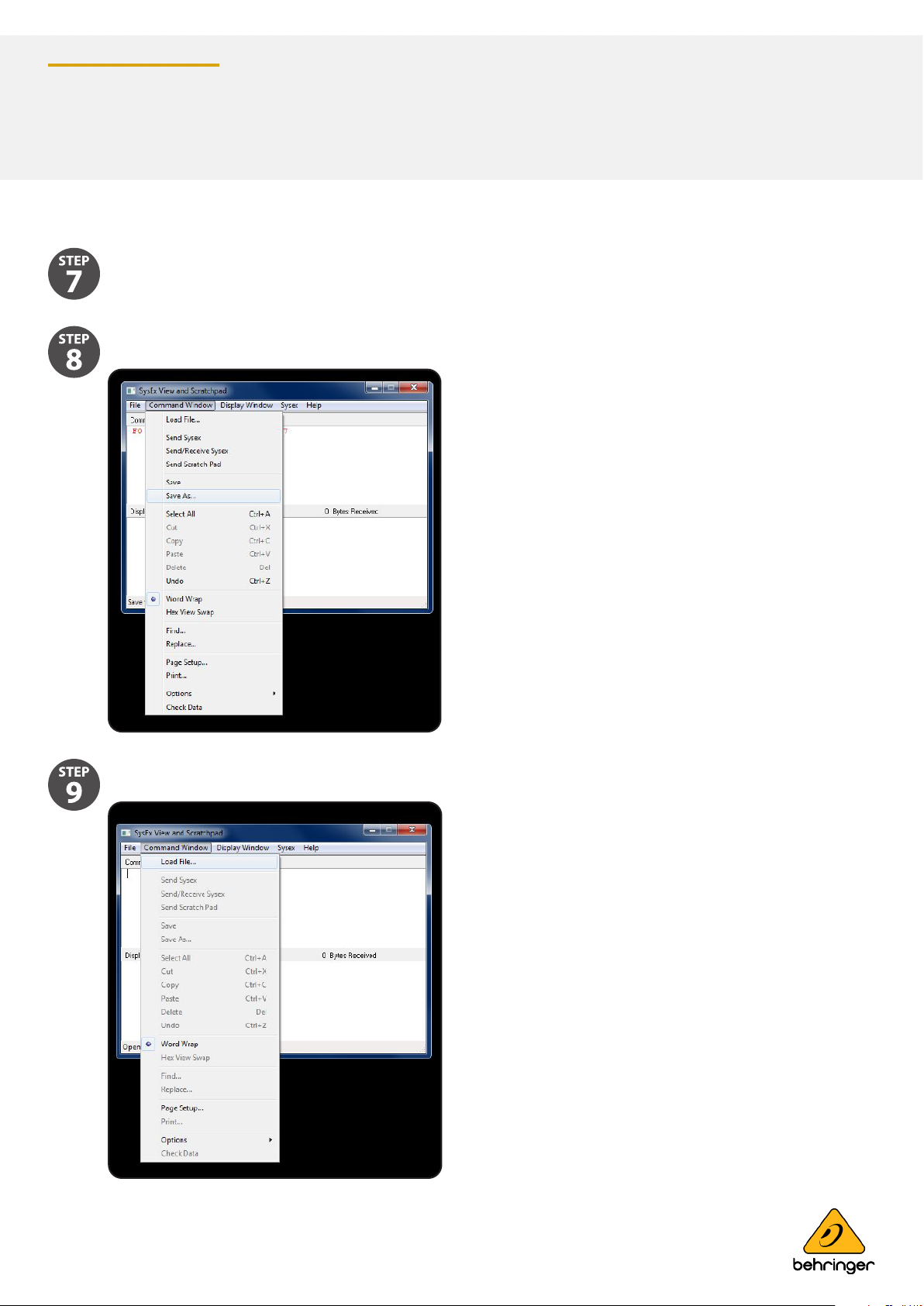
The SysEx message will be sent to the MODEL D, and it will then be in its PITCH Calibration mode.
If you wanted, you can use the SAVE AS command in the Command Window drop down menu to save the SysEx
message as a le on your computer for later use.
Then use the LOAD command in the Command Window drop down menu to recall the SysEx message from a le on
your computer.
page 11 of 23page 11 of 23
Page 12
Synthesizers and Samplers
DC Voltmeter
Voltmeter
0.001
MODEL D
Pitch CV Calibration continued
Follow the procedure on the previous page to put the MODEL D into PITCH Calibration mode using SysEx.
Make sure that the preliminary procedures shown in section 5.1 have been followed, and the MODEL D front panel
controls and switches are set as directed.
Set the Digital Voltmeter to measure a range below 10 VDC.S
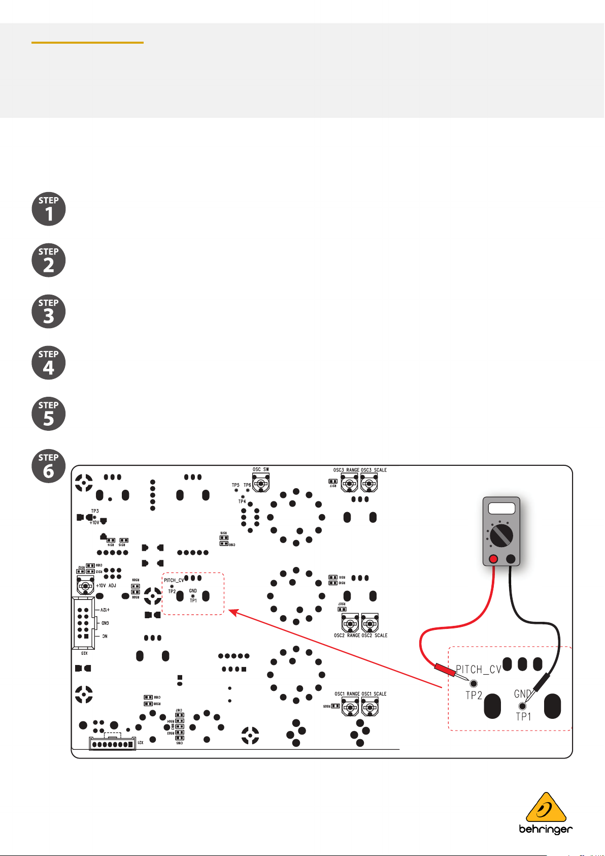
Locate the Test Points PITCH CV TP1 and TP2 on the bottom surface of the main PCB, as shown below.
Connect the positive probe of your Voltmeter to TP2.
Connect the negative probe of your Voltmeter to TP1 (ground).
page 12 of 23page 12 of 23
Page 13
Synthesizers and Samplers
C4C#4 D4 E4C3C#3 D3 E3 F3
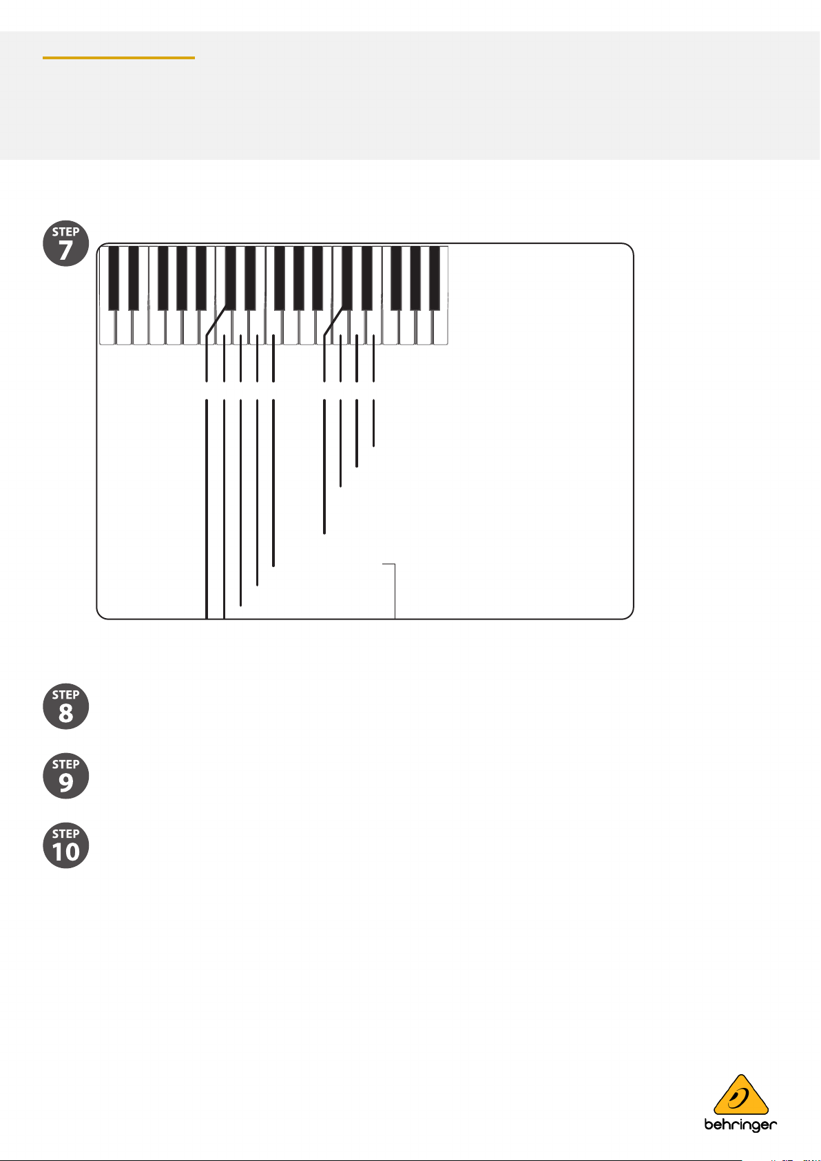
C4 Start Low Calibration. Target voltage is -2.500 Vdc
C#4 Exit Calibration Mode
D4 Start Zero Calibration. Target voltage is 0.000 Vdc
E4 Start High Calibration. Target voltage is 6.500 Vdc
D3 Decrement, Fine
E3 Increment, Fine
Press to increment or decrement
or
Press and hold to automatically
F3 Increment, Coarse
MODEL D
Connect the positive probe of your Voltmeter to TP2.
Low Calibration Adjustment
Press C4 on the external keyboard to set the Low calibration value.
Measure the output voltage. It should read -2.500 VDC.
If required, the output voltage can be adjusted to this value by pressing the following keys. The Pitch/CV output
adjustment resolution is about 2 mV
C3 = decrement coarse
D3 = decrement ne
E3 = increment ne
F3 = increment coarse
TIP: You can press and hold an increment or decrement key and (after a brief delay) the output adjustment will repeat
automatically until the key is released.
page 13 of 23page 13 of 23
Page 14
Synthesizers and Samplers
MODEL D
Zero Calibration Adjustment
Press D4 on the external keyboard to set the Zero calibration value.
Measure the output voltage. It should read 0.000 VDC.
If required, the output voltage can be adjusted to this value by pressing the following keys. The Pitch/CV output
adjustment resolution is about 2 mV
C3 = decrement coarse
D3 = decrement ne
E3 = increment ne
F3 = increment coarse
High Calibration Adjustment
Press E4 on the external keyboard to set the High calibration value.
Measure the output voltage. It should read +6.500 VDC.
If required, the output voltage can be adjusted to this value by pressing the following keys. The Pitch/CV output
adjustment resolution is about 2 mV
C3 = decrement coarse
D3 = decrement ne
E3 = increment ne
F3 = increment coarse
Saving the PITCH CV Calibration Settings
When you are done, you must press C#3 to save your calibration settings.
NOTE: If you do not do this, your changes will not be saved.
page 14 of 23page 14 of 23
Page 15
Synthesizers and Samplers
OSC3 Scale Adjustment
OSC3 Range Adjustment
Octave Adjustment
OSC1 Scale Adjustment
OSC1 Range Adjustment
OSC2 Range Adjustment
OSC2 Scale Adjustment
Highest A5
Lowest A2
Highest C6
MODEL D
Exiting the PITCH CV Calibration Procedure
When you are nished, you must press C#4 to exit the Calibration Mode and return the MODEL D to normal operation.
If you want to do the other calibrations for the oscillators and octave range, follow the procedures shown on the
next pages.
If you do not want to do any other calibrations, turn o the MODEL D, check the internal cables are securely connected,
and secure its front panel assembly back onto the chassis using the 8 screws.
Exiting the PITCH CV Calibration Procedure
If you want to restore the Pitch CV calibration back to its factory settings, send the SysEx command shown below. (See
the previous pages for details regarding the sending of SysEx messages.)
F0 00 20 32 00 7F 0F 00 00 00 F7
Oscillator Calibration
This calibration does not require the computer or SysEx, or the Voltmeter. An external keyboard is used, and adjustments are
made to the various trimpots.
There are two methods of oscillator calibration as shown on the next page.
The PCB and the location of the trimpots is shown below.
Note that the earlier version of the PCB has one-turn trim pots as shown, and the newer version uses multi-turn pots that
require a small at-headed screwdriver to adjust them
page 15 of 23page 15 of 23
Page 16
Synthesizers and Samplers
A2 Low Value A5 High Value
Oscillator Calibration
C6 Octave Calibration
MODEL D
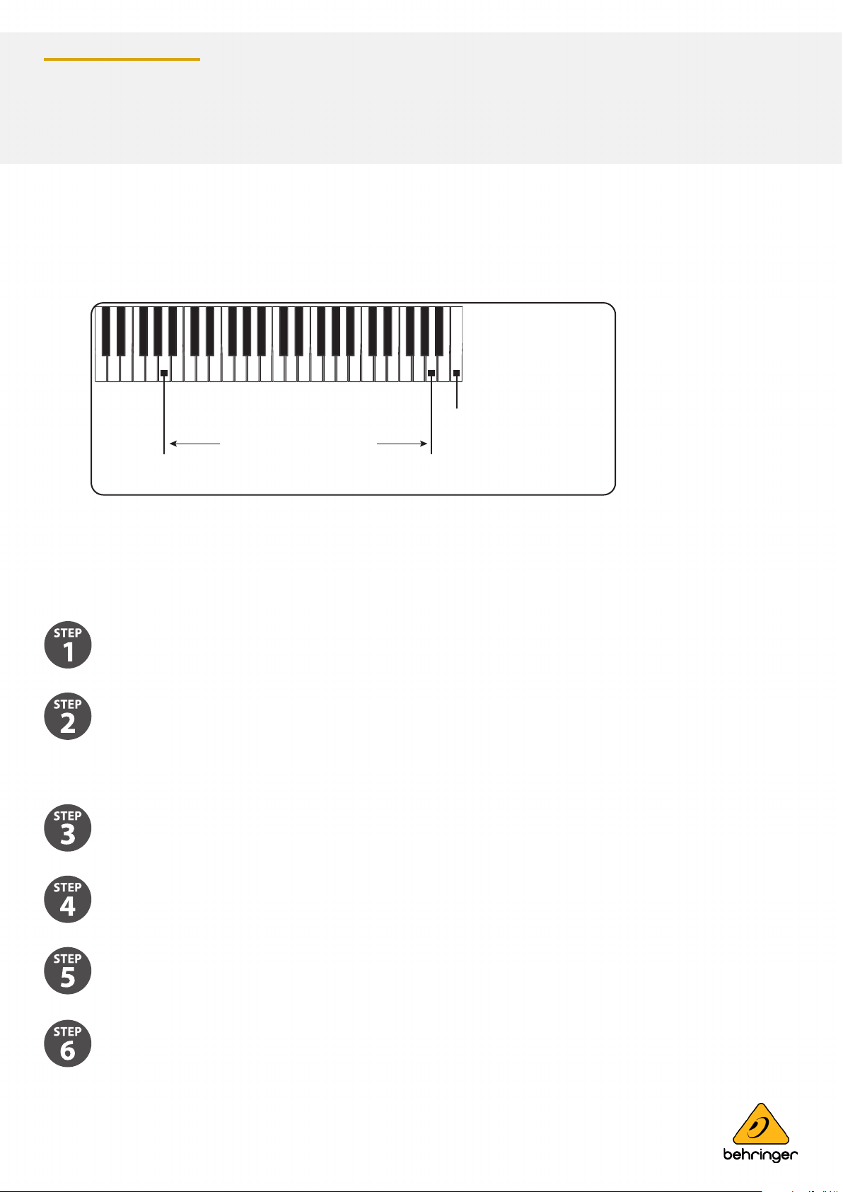
The diagram below shows the keyboard notes that are used in the calibrations. Only A2 and A5 are used in the Oscillator
calibration, and C6 is used in the Octave calibration.
Alternatively, notes may be played using a DAW with a MIDI interface connected to the MIDI IN on the MODEL D.
Calibration Procedure using a guitar tuner
This procedure is shown in a video made by our engineers, and we highly recommend that you take a look at the following link:
https://www.youtube.com/watch?v=-PwSISQrQEM&feature=youtu.be
Make sure that the preliminary procedures starting on page 3 above, have been followed, and the MODEL D front
panel controls and switches are set as directed. Except: turn the A-440 switch OFF.
Connect a guitar tuner to the rear panel main 1/4" output.
OSC1 Range and Scale Calibration
On the PCB, locate the OSC1 RANGE and OSC1 SCALE trimpots. (See PCB drawing on the previous page.)
Turn ON the OSC1 switch.
On your external keyboard, press and hold the A5 key and adjust the OSC1 RANGE trimpot on the PCB while observing
the tuner display.
On your external keyboard, press and hold the A2 key and adjust the OSC1 SCALE trimpot while observing the
tuner display.
page 16 of 23page 16 of 23
Page 17
Synthesizers and Samplers
MODEL D
Repeat steps 5 and 6 above until both notes are correct in the display. This may need to be repeated several times to
get right.
Turn OFF the OSC1 switch.
OSC 2 Scale and Range Calibration
On the PCB, locate the OSC2 RANGE and OSC2 SCALE pots.
Turn ON the OSC2 switch.
On your external keyboard, press and hold the A5 key and adjust the OSC2 RANGE trimpot on the PCB while observing
the tuner display.
On your external keyboard, press and hold the A2 key and adjust the OSC2 SCALE trimpot while observing the
tuner display.
Repeat steps 11 and 12 above until both notes are correct in the display. This may need to be repeated several times to
get right.
Turn OFF the OSC2 switch.
OSC 3 Scale and Range Calibration
Measure the output voltage. It sh On the PCB, locate the OSC3 RANGE and OSC3 SCALE pots
Turn ON the OSC3 switch.
On your external keyboard, press and hold the A5 key and adjust the OSC3 RANGE trimpot on the PCB while observing
the tuner display.
page 17 of 23page 17 of 23
Page 18
Synthesizers and Samplers
MODEL D
On your external keyboard, press and hold the A2 key and adjust the OSC3 SCALE trimpot on the PCB while observing
the tuner display.
Repeat steps 17 and 18 above until both notes are correct in the display. This may need to be repeated several times to
get right.
Turn OFF the OSC3 switch.
This completes the Oscillator Range and Scale Calibration.
If you want to do the other calibrations for the octave range, follow the procedures shown on the next pages.
If you do not want to do any other calibrations, turn o the MODEL D, check the internal cables are securely connected,
and secure its front panel assembly back onto the chassis using the 8 screws.
Calibration Procedure using A-440
Make sure that the preliminary procedures starting on page 3 above, have been followed, and the MODEL D
front panel controls and switches are set as directed.
OSC1 Range and Scale Calibration
On the PCB, locate the OSC1 RANGE and OSC1 SCALE trimpots. (See PCB drawing on the previous page.)
As set up in the preliminary procedure, make sure the A-440 switch is ON. The A-440 test tone should be playing in
your system.
On your external keyboard, press and hold the A5 key. Listen carefully, and adjust the OSC1 RANGE trimpot on the PCB
for zero beats
On your external keyboard, press and hold the A2 key. Listen carefully, and adjust the OSC1 SCALE trimpot on the PCB
for zero beats.
Repeat steps 4 and 5 above until there are zero beats for either note. This may need to be repeated
several times to get this right.
page 18 of 23page 18 of 23
Page 19
Synthesizers and Samplers
MODEL D
Turn OFF the A-440 switch.
Make sure the OSC1 switch is left ON for the next calibration.
OSC 2 Scale and Range Calibration
On the PCB, locate the OSC2 RANGE and OSC2 SCALE pots.
As set up in the previous procedure, the A-440 test tone should be o, and the OSC1 switch should be set on.
Turn on the OSC2 switch.
On your external keyboard, press and hold the A5 key. Listen carefully to the combination of OSC1 and OSC2, and
adjust the OSC 2 RANGE trimpot on the PCB for zero beats between them.
On your external keyboard, press and hold the A2 key. Listen carefully to the combination of OSC1 and OSC2, and
adjust the OSC2 SCALE trimpot on the PCB for zero beats between them.
Repeat steps 11 and 12 above until there are zero beats for either note. This may need to be repeated several times to
get this right.
Turn OFF the OSC2 switch.
Make sure the OSC1 switch is left on, for the next calibration.
OSC 3 Scale and Range Calibration
On the PCB, locate the OSC3 RANGE and OSC3 SCALE pots.
As set up in the previous procedure, the A-440 test tone should be o, and the OSC1 switch should be set on.
Turn on the OSC3 switch.
page 19 of 23page 19 of 23
Page 20
Synthesizers and Samplers
MODEL D
On your external keyboard, press and hold the A5 key. Listen carefully to the combination of OSC1 and OSC3, and
adjust the OSC3 RANGE trimpot on the PCB for zero beats between them.
On your external keyboard, press and hold the A2 key. Listen carefully to the combination of OSC1 and OSC3, and
adjust the OSC3 SCALE trimpot on the PCB for zero beats between them.
Repeat steps 18 and 19 above until there are zero beats for either note. This may need to be repeated several times to
get this right.
Turn OFF the OSC3 switch.
This completes the Oscillator Range and Scale Calibration.
If you want to do the other calibrations for the octave range, follow the procedures shown on the next pages.
If you do not want to do any other calibrations, turn o the MODEL D, check the internal cables are securely connected,
and secure its front panel assembly back onto the chassis using the 8 screws.
Octave Range Calibration
The octave calibration ensures that the OSC1 and OSC2 Octave RANGE knobs are in tune with each other. This calibration is
done after the oscillator calibration.
Make sure that the preliminary procedures shown in section 5.1 have been followed, and the MODEL D front panel
controls and switches are set as directed.
Turn OFF the A-440 switch, and keep the OSC1 VOLUME switch ON.
page 20 of 23page 20 of 23
Page 21
Synthesizers and Samplers
OSC3 Scale Adjustment
OSC3 Range Adjustment
Octave Adjustment
OSC1 Scale Adjustment
OSC1 Range Adjustment
OSC2 Range Adjustment
OSC2 Scale Adjustment
Highest A5
Lowest A2
Highest C6
MODEL D
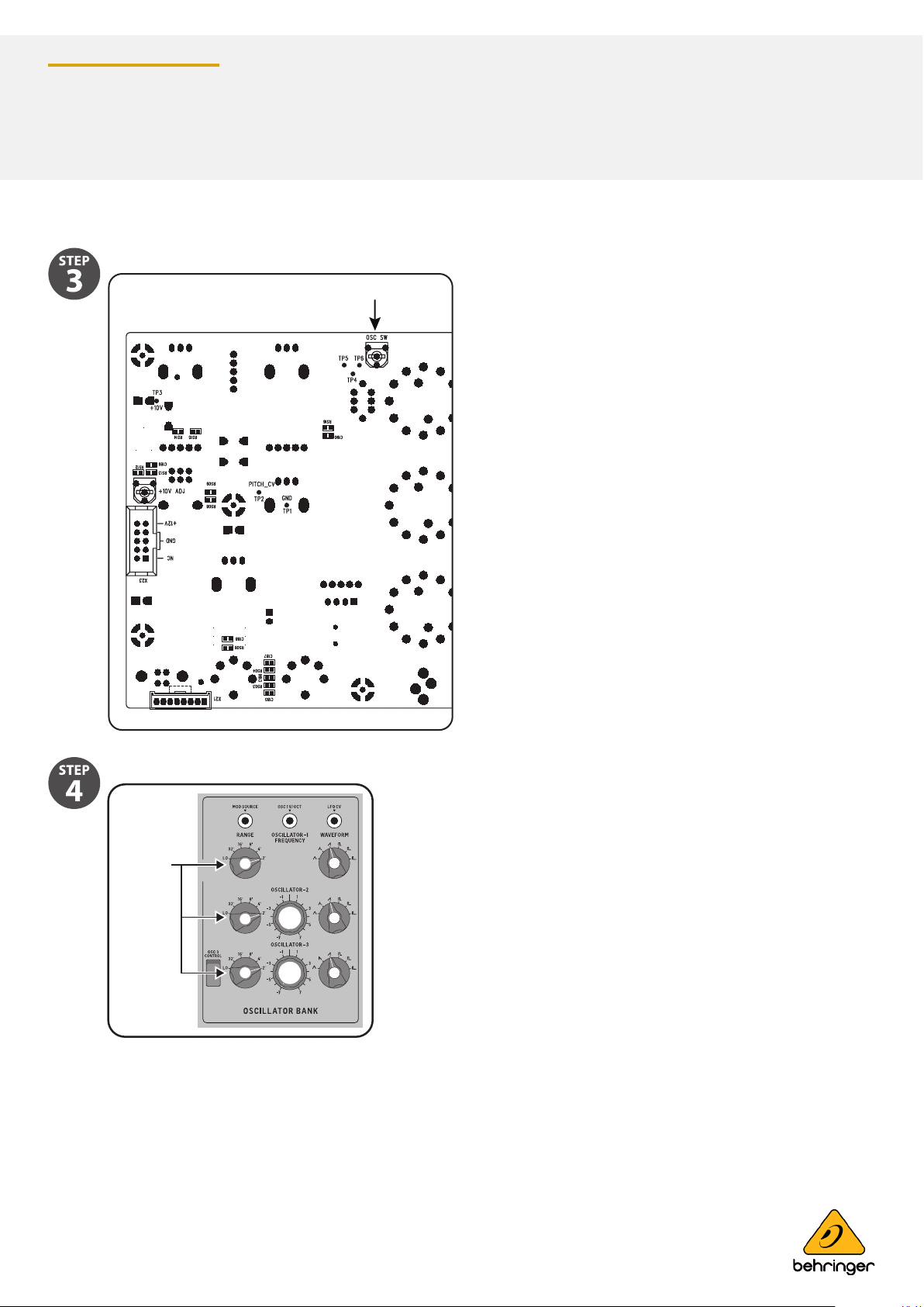
On the PCB, locate the OSC SW pot
Turn all the Octave RANGE knobs to the 2' position in the OSCILLATOR BANK section.
RANGE
page 21 of 23page 21 of 23
Page 22
Synthesizers and Samplers
OSC2 ON
OSC1 ON
OSC1 Max
OSC2 Max
MODEL D
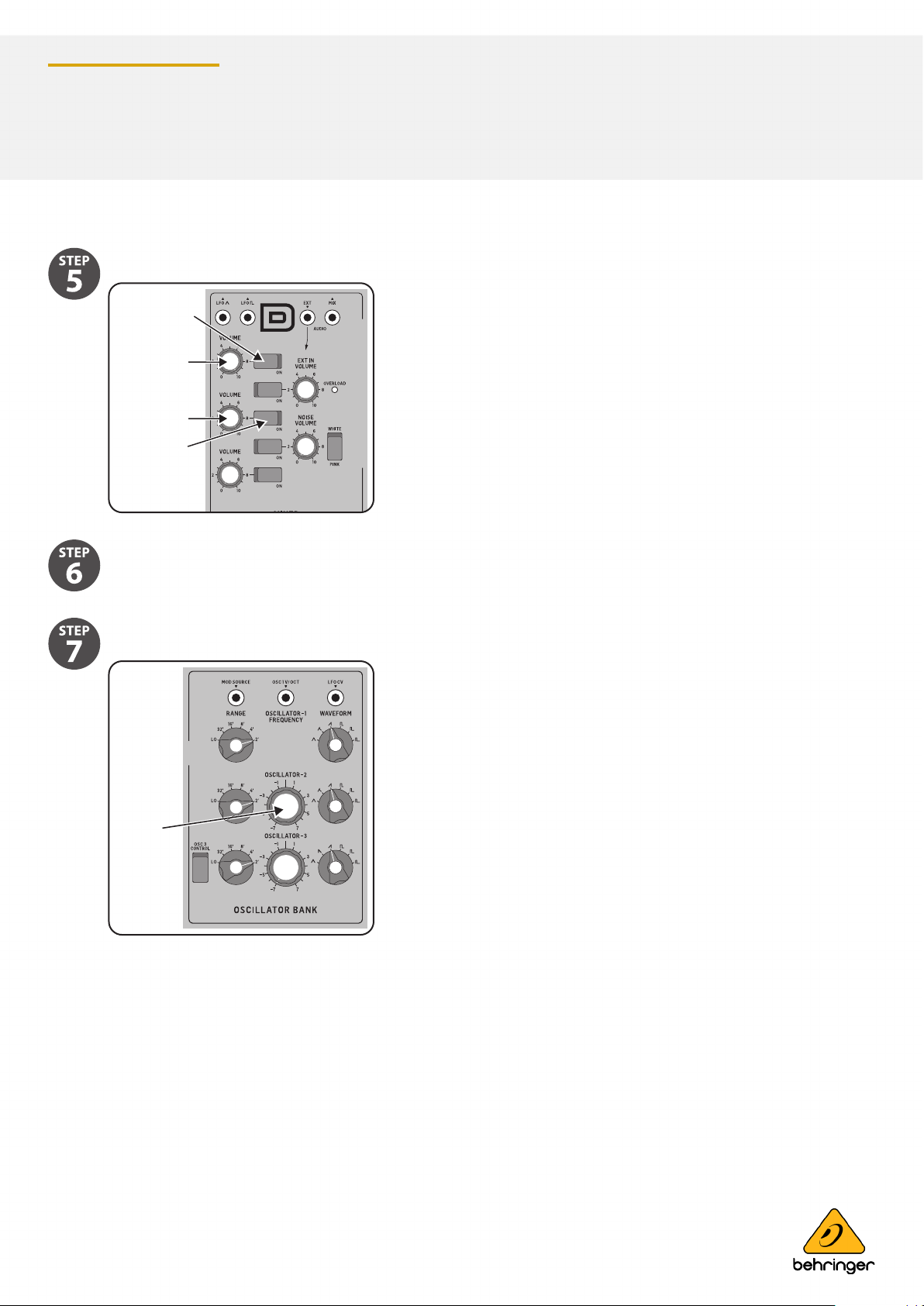
Turn on the front panel OSC2 VOLUME switch in the MIXER section. (OSC1 is already on, OSC1 and 2 Volumes are up).
On your external keyboard, press and hold the C6 key. You should hear both OSC1 and OSC2. Adjust the headphone
volume or main volume as required.
Listen carefully, and adjust the front panel OSCILLATOR-2 Tune knob until there are zero beats between
OSC1 and OSC2.
TUNE
page 22 of 23page 22 of 23
Page 23
Synthesizers and Samplers
A2 Low Value A5 High Value
Oscillator Calibration
C6 Octave Calibration
OSC3 Scale Adjustment
Octave Adjustment
Highest A5
Lowest A2
Highest C6
MODEL D
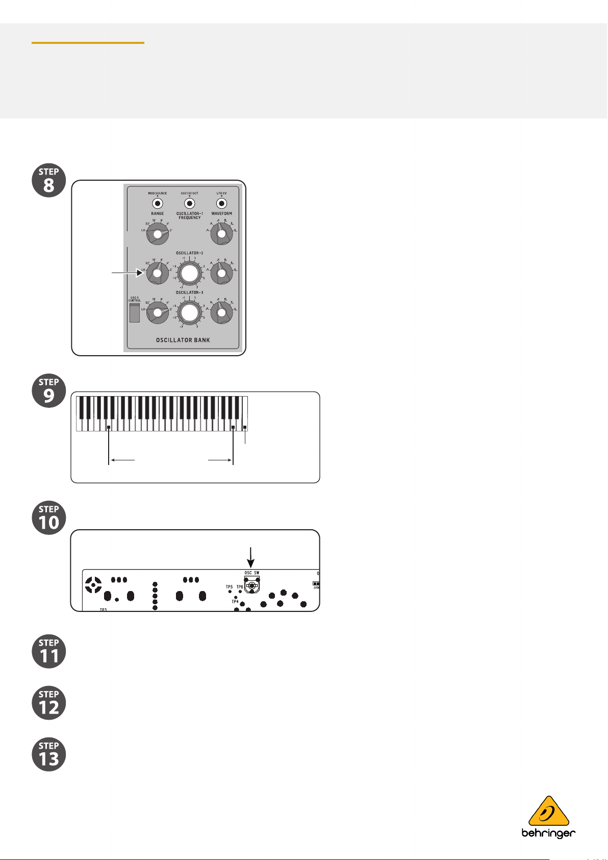
Turn the front panel OSC2 Octave RANGE knob to the 8' position.
RANGE
8’
On the PCB, locate the OSC2 RANGE and OSC2 SCALE pots.
Listen carefully, and adjust the OSC SW trimpot on the PCB, for zero beats between OSC1 (Range=2') and
OSC2 (Range=8').
Repeat step 8 with dierent settings of the RANGE knob, and repeat steps 9 and 10 until both oscillators are in tune
with each other at all settings of the Octave RANGE knob.
This completes the Octave Range Calibration.
If you do not want to do any other calibrations, turn o the MODEL D, check the internal cables are securely connected,
and secure its front panel assembly back onto the chassis using the 8 screws.
Music Tribe accepts no liability for any loss which may be suered by any person who relies either wholly or in part upon any description, photograph, or statement contained herein.
Technical specications, appearances and other information are subject to change without notice. All trademarks are the property of their respective owners. Midas, Klark Teknik,
Lab Gruppen, Lake, Tannoy, Turbosound, TC Electronic, TC Helicon, Behringer, Bugera, Oberheim, Auratone and Coolaudio are trademarks or registered trademarks of Music Tribe Global
Brands Ltd. © Music Tribe Global Brands Ltd. 2021 All rights reser ved.
Condential, for internal use only. Not to be reproduced.
 Loading...