

Page 1
INPUT OUTPUT
User Manual
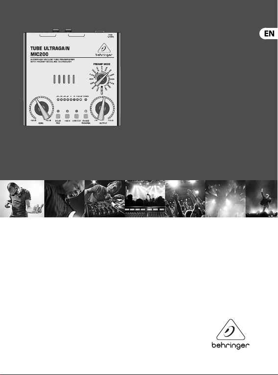
TUBE ULTRAGAIN MIC200
Audiophile Vacuum Tube Preamplier with
Preamp Modeling Technology
Page 2

2 TUBE ULTRAGAIN MIC200 User Manual
Table of Contents
Thank you ............................................................................................ 2
Important Safety Instructions ........................................................... 3
Legal Disclaimer .................................................................................. 5
Limited Warranty ................................................................................ 5
1. Introduction .................................................................................... 6
1.1 The design concept ...................................................................................... 6
1.2 Online registration ....................................................................................... 7
2. Control Elements ............................................................................ 8
2.1 User interface ................................................................................................. 9
2.2 Rear panel ......................................................................................................12
3. Wiring Examples .......................................................................... 13
3.1 Enhancing vocals and instruments in
live applications ..................................................................................................13
3.2 “Direct to Disk” application in studio or
homerecording environments ......................................................................14
3.3 The MIC200 as DI-box ............................................................................... 15
4. Audio Connectors ........................................................................ 16
5. Specications ............................................................................... 18
Thank you
Thank you for the condence you have placed in us by purchasing the MIC20 0.
Your MIC200 is a profe ssional mic preamp that can be used in a variety of
applications. Due to its incredible f unctionality and t he broad range of connection
options, the MIC200 can even be used as a preamp for elec tric and bass guitars,
keyboards and percussion instruments. No matter where you use your MIC200,
you always get optimal performance, be it live or on the stage, in a professional
recording s tudio or at home!
Page 3

3TUBE ULTRAGAIN MIC200 User Manual TUBE ULTRAGAIN M IC200 User Manual
Caution
Do not use this apparatus near water.
Important Safety Instructions
Terminals marked with this
symbol carry electrical
current of su cient
magnitude to constitute risk of electric
shock. Use only high-quality professional
speaker cables with ¼" TS or twist-locking
plugs pre-installed. Allother installation
or modi cation should be performed only
by quali edpersonnel.
This symbol, wherever it
appears, alertsyou to the
presence of uninsulated
dangerous voltage inside the
enclosure-voltage that may be su cient
to constitute a risk ofshock.
This symbol, wherever it
appears, alertsyou to
important operating and
maintenance instructions in the
accompanying literature. Please read
themanual.
To reduce the risk of electric
shock, donot remove the
top cover (or the rear section). No user
serviceable parts inside. Refer servicing to
quali ed personnel.
Caution
To reduce the risk of re or
electric shock, do not expose
this appliance to rain and moisture.
The apparatus shall not be exposed to
dripping or splashing liquids and no
objects lled with liquids, suchas vases,
shall be placed on the apparatus.
Caution
These service instructions
are for use by quali ed
service personnel only. Toreduce the
risk of electric shock do not perform any
servicing other than that contained in the
operation instructions. Repairs have to be
performed by quali ed servicepersonnel.
1. Read these instructions.
2. Keep these instructions.
3. Heed all warnings.
4. Follow all instructions.
5.
6. Clean only with dry cloth.
Page 4

4 TUBE ULTRAGAIN MIC200 User Manual
7. Do not block any ventilation
13. Unplug this apparatus during
openings. Install in accordance with the
manufacturer’s instructions.
8. Do not install near any heat sources
such as radiators, heat registers, stoves,
or other apparatus (including ampli ers)
that produce heat.
9. Do not defeat the safety purpose
of the polarized or grounding-type plug.
Apolarized plug has two blades with one
wider than the other. A grounding-type
plug has two blades and a third grounding
prong. The wide blade or the third
prong are provided for your safety. Ifthe
provided plug does not t into your outlet,
consult an electrician for replacement of
the obsolete outlet.
10. Protect the power cord from being
walked on or pinched particularly at plugs,
convenience receptacles, and the point
where they exit from the apparatus.
11. Use only attachments/accessories
speci ed by themanufacturer.
12. Use only with
the cart, stand, tripod,
bracket, or table speci ed
by the manufacturer,
orsold with the apparatus. When a cart is
used, use caution when moving the cart/
apparatus combination to avoid injury
from tip-over.
lightning storms or when unused for long
periods of time.
14. Refer all servicing to quali ed
service personnel. Servicing is required
when the apparatus has been damaged
in any way, such as power supply cord or
plug is damaged, liquid has been spilled
or objects have fallen into the apparatus,
the apparatus has been exposed to rain or
moisture, does not operate normally, or
has beendropped.
15. The apparatus shall be connected to
a MAINS socket outlet with a protective
earthing connection.
16. Where the MAINS plug or an
appliance coupler is used as the
disconnect device, the disconnect device
shall remain readily operable.
Page 5

5TUBE ULTRAGAIN MIC200 User Manual TUBE ULTRAGAIN M IC200 User Manual
MEANS, ELECTRONIC OR MECHANICAL,
LEGAL DISCLAIMER
TECHNICAL SPECIFICATIONS AND
APPEARANCES ARE SUBJECT TO
CHANGE WITHOUT NOTICE AND
ACCURACY IS NOT GUARANTEED.
BEHRINGER, KLARKTEKNIK, MIDAS,
BUGERA, AND TURBOSOUND
ARE PART OF THE MUSIC GROUP
MUSICGROUP.COM. ALL
TRADEMARKS ARE THE PROPERTY
OF THEIR RESPECTIVE OWNERS.
MUSICGROUP ACCEPTS NO LIABILITY
FOR ANY LOSS WHICH MAY BE
SUFFERED BY ANY PERSON WHO RELIES
EITHER WHOLLY OR IN PART UPON
ANY DESCRIPTION, PHOTOGRAPH
OR STATEMENT CONTAINED HEREIN.
COLORS AND SPECIFICATIONS MAY
VARY FROM ACTUAL PRODUCT.
MUSICGROUP PRODUCTS ARE
SOLD THROUGH AUTHORIZED
FULLFILLERS AND RESELLERS ONLY.
FULLFILLERSAND RESELLERS ARE
NOT AGENTS OF MUSICGROUP AND
HAVE ABSOLUTELY NO AUTHORITY
TO BIND MUSICGROUP BY ANY
EXPRESS OR IMPLIED UNDERTAKING
OR REPRESENTATION. THIS MANUAL
IS COPYRIGHTED. NO PART OF THIS
MANUAL MAY BE REPRODUCED OR
TRANSMITTED IN ANY FORM OR BY ANY
INCLUDING PHOTOCOPYING
AND RECORDING OF ANY KIND,
FORANY PURPOSE, WITHOUT THE
EXPRESS WRITTEN PERMISSION OF
MUSICGROUPIPLTD.
ALL RIGHTS RESERVED.
© 2013 MUSICGroupIPLtd.
Trident Chambers, Wickhams Cay,
P.O. Box 146, Road Town, Tortola,
British Virgin Islands
LIMITED WARRANTY
For the applicable warranty terms
and conditions and additional
information regarding MUSICGroup’s
Limited Warranty, pleasesee
complete details online at
www.music-group.com/warranty.
Page 6

6 TUBE ULTRAGAIN MIC200 User Manual
1. Introduction
With the MIC20 0, you have purchased an extremely musical mic preamp that is
equipped with a 12AX7 vacuum tube. Thanks to BEHRINGER’s preamp modeling,
its main advantages are the number of preamp settings you can select. Additionally,
features like an integrated limiter, phase revers e function, phantom power supply,
highly accurate LED meter, switchable pad func tion and low cut lter make the
MIC200 a ver y powerful piece of equipment.
1.1 The design concept
The heart of the TUBEULTRAGAIN is an ex tremely low-noise microphone preamp
circuitr y that uses discrete components and produces a highly trans-parent
sound. In combination with our BEHRINGER tube te chnology, the operational
ampliers 4580 and a sophisticated circuit topolo gy, the TUBEULTRAGAIN y ields
excellent noise and distor tion properties. The innovative UTC circuitr y that has
been developed by our engineering team oers an abundance of sound-shaping
possibilities. Absolu te musicality was our major goal when we designed the
TUBE ULTRAGAIN. The result is a device that, thanks to our tube circuitry, lends an
incredible punch to percussion instruments. On the other hand, instruments that
are rich in upp er harmonics will receive more transparency. The sound will be warm,
detailed and brilliant.
Surely you know the recording problem that single instruments or vocals sometimes
don’t cut through. Thanks to the TUBEULTRAGAIN, vocals gain in presence and
volume without masking other instruments. As a result, your voice will be perfectly
integrated in the mix.
Page 7

7TUBE ULTRAGAIN MIC200 User Manual TUBE ULTRAGAIN M IC200 User Manual
1.2 Online registration
Please regis ter your new BEHRINGER equipment right after your purchase by visiting
http://behringer.com and read the terms and conditions of our warranty carefully.
Should your BEHRINGER product malfunc tion, it is our intention to have it repaired
as quickly as possible. To arrange for warrant y service, please contact the BEHRINGER
retailer from whom the equipment was purchased. Should your BEHRINGER dealer
not be located in your vicinity, you may direc tly contact one of our subsidiaries.
Corresponding contact information is included in the original equipment packaging
(Global Contac t Information/European Contact Information). Should your country
not be listed, please contac t the distributor nearest you. A list of distributors can be
found in the support area of our website (http://behringer.com).
Registering your purchase and equipment with us helps us process your repair claims
more quickly and eciently.
Thank you for your cooperation!
Page 8

8 TUBE ULTRAGAIN MIC200 User Manual
2. Control Elements
INPUT OUTPUT
Fig. 2.1: User inter face of the MIC 200
(9)(1) (2) (4) (5) (6) (7) (3) (8)
Page 9

9TUBE ULTRAGAIN MIC200 User Manual TUBE ULTRAGAIN M IC200 User Manual
2.1 User interface
(1) The GAIN control allows you to control the gain from +26 to +60 dB to
the input signal. This control should be set all theway to the lef t when (dis)
connecting a sound source from the MIC200. When all connections are made,
slowly star t raising the gain control.
(2) We recommend using the LED meter to adjus t gain. The LED chain displays the
output signal level in dB. Please make sure that the clip LED never lights up
permanently. It should light up only at p eak signals, but it should never be on
all the time.
(3) If your MIC200 is connected to the mains via the enclosed power supply unit,
the POWER LED lights up to indicate that your MIC200 is r unning.
(4) The 20 dB PAD switch reduces the input sensitivity by 20 dB (switchpressed).
The appropriate setting depends on the equipment connected. Generally
speaking, lower ing the signal level in mic applications is not recommended.
No matter what your application is, the clip LED warns you to reduce the gain
setting to avoid distortion.
(5) This +48 V s witch activates the phantom power supply for the XLR input.
Phantom power supply is required for operating condenser microphones.
Dynamic microphones require no phantom power.
(6) Press the LOW CUT switch to eliminate undesired subsonic noise, such as
oor rumble.
(7) With the PHASE REVERSE switch, the input signal is reversed by 180°.
This func tion is available for both mic and line signals. Use this function
in a multi-mic rophone setup if you detect phase c ancellations in specic
frequency bands.
Page 10

10 TUBE ULTRAGAIN MIC200 User Manual
(8) The OUTPUT cont rol governs the output level within a range from
-∞to+10dB. If the control is turned all the way to the lef t, there is no
output signal at all. The more the control is tur ned to the right, the higher the
output level.
(9) The PREAMP MODE rotary switc h gives you a wide selection of
preamppresets. The options available are: WARM, WARM/LIMITER,
LIMITERandNEUTRAL :
WARM (moving clockwise, starting at 9 o’clock):
These set tings make sense if you wish to add that typical warmth associated with
analog signals.
• KE YB: For electronic keybo ard instruments of all t ypes
• E-GTR: Elec tric guitar
• VOCAL: Speech and vocals
• VALVE: Warm, analog tube sound
WARM + LIMITER (moving cloc kwise, starting at 12o’clock):
Use these settings when working with high volumes or with sounds with fre quent
signal peaks, and if direc tly recording an instr ument with a mic (e. g. drums) to insert
additional warmth.
• MULTI: Various applications
• VOCAL: Speech and vocals
• A-GTR: Acoustic guitar
• PIANO: Piano/grand piano
Page 11

11TUBE ULTRAGAIN MIC200 User Manual TUBE ULTRAGAIN M IC200 User Manual
LIMITER (moving clockwise, starting at 3 o’clock):
Select these set tings if you wish to use the limiter funct ion without adding
tube warmth.
• BASS: Bass guitar
• A-GTR: Acoustic guitar
• PERC: Percussion and dr ums
• LIMIT: Neutral limiter setting
NEUTRAL (moving clockwise, star ting at 6 o’clock):
These set tings are ideal for neutral and natural sound reproduction without limiter
and without tube sound.
• NEUTRAL: Neutral sound setting
• VOCAL: Optimize d setting for speech and vocals
• GUITAR: Optimized setting for guitars and guitar amps
• BASS: Optimized setting for electr ic bass guitar
◊ Since presets cannot cover all possible applications, experiment with
different set tings until you find those that work best for you. Think of
presets as the starting points for your sound configuration.
Page 12

12 TUBE ULTRAGAIN MIC200 User Manual
2.2 Rear panel
(12)
Fig. 2.2: T he rear panel of yo ur MIC200
(10) The balanced ¼" TRS INPUT of your MIC200 can be used to connec t your
electr ic guitar, for example. This input is wired parallelly to the XLR input.
Ideally, the balanced XLR INPUT should be used to connecta microphone.
◊ In contrast to its outputs, the MIC200’s inputs should never be
used simultaneously!
(11) This is the balanced XLR OUTPUT of your MIC200. Use this conne ctor to feed the
XLR input of your mixing console, multitrac k recorder or power amp.
The balanced ¼" TRS OUTPUT of your MIC200 can also be connected to a mixer,
recording system or power amp.
(12) Use the POWER SUPPLY CONNECTOR to hook up the enclosed power supply
unit. Nex t to this connector you’ll nd the strain relief clamp, which prevents
accidental release of the power supply.
The device’s SERIAL NUMBER is found on the bottom side of the unit.
(11)
(10)
Page 13

13TUBE ULTRAGAIN MIC200 User Manual TUBE ULTRAGAIN M IC200 User Manual
3. Wiring Examples
You’ll be surprised how exibly you can set up your MIC200. The following chapter
describes some typical wiring examples.
3.1 Enhancing vocals and instruments in live applications
Here, the MIC200 is wired bef ore the mixer’s channel input. Thus, the sound gains
in warmth and transparenc y. Thank s to the limiter setting f or vocals (VOCAL),
distortion is eliminate d eectively.
XLR-input XLR-output Microphone input
INPUT OUTPUT
Fig. 3.1: Standard li ve applicati on
Page 14

14 TUBE ULTRAGAIN MIC200 User Manual
3.2 “Direct to Disk” application in studio or homerecording environments
If you are looking for a device that considerably enhances the s ound of your digital
workst ation, this is where the MIC200 comes in. Many hard disk recorders lack a
certain “liveliness”. In addition, they are of ten equipped with “lous y” microphone
preamps. Such p roblems can be solved per fectly with the MIC200.
¼" TRS outputXLR input
INPUT OUTPUT
Fig. 3.2: Con nection of t he MIC200 and t he soundcar d of your PC
Page 15

15TUBE ULTRAGAIN MIC200 User Manual T UBE ULTRAGAIN MIC200 User M anual
3.3 The MIC200 as DI-box
Your MIC200 is excellently suited for this application. For example, you can connect
an unbalanced acoustic guit ar signal to the MIC200 to prevent hum or interf erence
noise. What you get is a balanced, noise-free signal.
¼" TRS output
Fig. 3.3: The MI C200 as DI-b ox
¼" TRS
input
INPUT OUTPUT
XLR output
Insert
Microphone input
Page 16

16 TUBE ULTRAGAIN MIC200 User Manual
4. Audio Connectors
Balanced use with XLR connectors
1
12
3
2
3
input
1 = ground/shield
2 = hot (+ve)
3 = cold (-ve)
Fig. 4.1: XLR connec tors
Unbalanced ¼" TS connector
Fig. 4.2: ¼" TS co nnector
output
For unbalanced use,
pin 1 and pin 3
have to be bridged
strain relief clamp
sleeve
tip
sleeve
(ground/shield)
tip
(signal)
Page 17

17TUBE ULTRAGAIN MIC200 User Manual TUBE ULTRAGAIN MIC20 0 User Manual
Balanced ¼" TRS connector
strain relief clamp
sleeve
ring
tip
sleeve
ground/shield
ring
cold (-ve)
tip
hot (+ve)
For connection of balanced and unbalanced plugs,
ring and sleeve have to be bridged at the stereo plug.
Fig. 4.3: ¼" TRS co nnector
Page 18

18 TUBE ULTRAGAIN MIC200 User Manual
5. Specications
Audio Inputs
XLR Input
Connector balanced / unbalanced
Type transformerless, DC- decoupledinput
Impedanc e approx. 2k Ω
Max. inpu t level +7dBu / -20 dB with pad
¼" TRS Input
Connector balanced / unbalanced
Type transformerless, DC- decoupledinput
Impedanc e approx. 1MΩ
Max. inpu t level +16dBu / -20 dB wi th pad
E.I.N.1 (20 Hz - 20 kHz)
@ 0Ω source re sistance -125.5dBu / -128.5dB u A-weighted
@ 150Ω source resi stance -124dBu / -126.8dBu A-wei ghted
@ 600Ω sour ce resistance -120dBu / -122.7dBu A- weighted
Audio Outputs
Connec tors XLR conne ctor + ¼" TRS jack balance d / unbalanced
Type transformerless, DC-decoupledoutput
Impedanc e approx. 70 0Ω balanced, approx.350Ω u nbalanced
Max. out put level approx. +26dBu @ 100kΩ
Page 19

19TUBE ULTRAGAIN MIC200 User Manual T UBE ULTRAGAIN MIC200 User Ma nual
System Da ta
Signal-to -noise ratio 90dB A-weig hted @ -28dBu inputlevel
Frequency Response
Mic input <10Hz to 47kHz (±3dB)
Line inpu t <10Hz to 55kHz (±3dB)
Function Controls
GAIN variable (+26dB to +60dB)
OUTPUT variable (-∞ t o +10dB)
Preamp mod e control selec tion of various pre amp settings f or microphone
andinstruments
Function Switches
20 dB PAD level at tenuation (20dB)
+48 V activ ates the phantom powe r
LOW CUT High pass l ter (cut-ofreque ncy90Hz)
PHASE REVER SE Ph ase reverse (180°)
Indicators
Input Level 8-segm ent LED meter:
-24, -18, -12, -6, 0, +6, +12, Cli p
Power LED indic ates operation
Page 20

20 TUBE ULTRAGAIN MIC200 User Manual
Power Supply
Mains Voltage
USA/Canad a 120V~, 60Hz
Europe/ U.K./Australia 230V~, 50Hz
China 220V~, 50Hz
Korea 220V~, 60Hz
Japan 100V~, 50 / 60Hz
Mains conne ctor exter nal power supply 9V~ / 1300mA
Physic al / Weight
Dimensio ns (H x W x D) approx . 2.5 x 5.3 x 5.3" / 64x 135x 135mm
Weight (witho ut power supply) ap prox. 1.0kg
1
Equivalent Input Noise
BEHRING ER is constant ly strivin g to maintain the h ighest prof essional st andards. As a r esult of thes e effor ts,
modifi cations may be m ade from tim e to time to exis ting produc ts withou t prior notice . Specific ations and app earance
may dif fer from tho se listed or illu strated.
Page 21

We Hear You
 Loading...