

Page 1
A B
EUROCOM MA6018
A
B
C
A B
D
Quick Start Guide (Check out behringer.com for FullManual)
EUROCOM
MA6480A
Energy-Ecient, Multi-Function 240-Watt Mixing Amplier with
Dual70/100 V and 4 Ω Outputs
MA6018/MA6008
Energy-Ecient, Multi-Function 180/80-Watt Auto-Mixing Amplier with
Dual 70/100 V and 4 Ω Outputs
MA6000M
Energy-Ecient, 13-Input Expandable Mixer Featuring Auto-Mixing and
Multiple Input Connectivity
Page 2
1. Read these instructions.
15. The appar atus shall be connected to
lluvia, humedad o alguna otra fuente que
11. Use únicamente los di spositivos o
2 3Quick Start GuideEUROCOM MA648 0A/MA6018/MA6008 /MA6000 M
Important Safety
Instructions
Terminals marked with this
symbol c arry electri cal
current of su cient
magnitude to constitute risk of electric
shock. Use only high -quality professional
speaker cable s with ¼" TS or twistlocking plug s pre-installed. Allother
installation or modi cation should be
perfo rmed only by quali edpersonnel.
This symbol, wherever it
appears, aler ts you to the
presence of uninsulated
dangerous voltage inside the enclosure
-voltage that may be su cient to
constitute a risk o fshock.
This symbol, wherever it
appears, aler tsyou to
important operating and
maintenance instructions in the
accompanying literat ure. Please read
themanual.
Caution
To reduce the risk of elec tric
shock, do not rem ove the
top cover (or the rear sec tion). No user
serviceable part s inside. Refer servicing
to quali edpersonnel.
Caution
To reduce the risk of re or
electr ic shock, do not expos e
this appliance to rai n and moisture.
Theapparatu s shall not be exposed to
dripping or splashing liquids and no
objects lled with liq uids, such as vases,
shall be placed on the ap paratus.
Caution
These service instruc tions
are for use by qual i ed
service p ersonnel only. Toreduce the
risk of elec tric shock do not perfo rm any
servicing other than that contained in the
operation i nstructions. Rep airs have to be
perfo rmed by quali ed serviceperso nnel.
2. Keep these instruc tions.
3. Heed all warnings.
4. Follow all instructions .
5. Do not use this apparatus
nearwater.
6. Clean only with dry cloth.
7. Do not bloc k any ventilation
openings. Ins tall in accordance with the
manufacturer ’s instructions.
8. Do not install near any heat sources
such as radiator s, heat registers, stoves,
orother appar atus (including ampli ers)
thatproduceheat.
9. Do not defeat the sa fety purpose
of the polarized or grounding-type plug.
Apolarized plu g has two blades with
one wider than the other. A groundingtype plug has t wo blades and a third
grounding prong. The wide blade or the
third prong a re provided for your safe ty.
Ifthe provided p lug does not t in to
your outlet, cons ult an electrician for
replacement of t he obsoleteoutlet.
10. Protect the power cord fr om being
walked on or pinc hed particularly at
plugs, convenience receptac les, and
the point where they exit from the
apparatus.
11. Use only attachments/accessories
speci ed by themanufac turer.
12. Use only with
the cart , stand,
tripod, bracket,
ortable speci ed by
the manufacturer,
orsold with
the apparat us. When a cart is used,
usecaution when moving the cart/
apparatus com bination to avoid injury
from tip-over.
13. Unplug this apparatus during
lightning storms or when unused for long
periods oft ime.
14. Refer all s ervicing to quali ed
service personnel. Servicing is required
when the apparat us has been damaged
in any way, such as power suppl y cord or
plug is damaged, liquid has b een spilled
or object s have fallen into the apparatus,
the apparatu s has been exposed to rain
or moistur e, does not o perate normally,
or has beendrop ped.
a MAINS socket outl et with a protective
earthingconnection.
16. W here the MAINS plug or an
appliance coupler is used as the
disconnec t device, thedisconnect device
shall remain readi lyoperable.
LEGAL DISCLAIMER
TECHNICAL SPECIFICATIONS AND
APPEARANCES ARE SUBJECT TO CHANGE
WITHOUT NOTICE AND ACCURACY
IS NOT GUARANTEED. BEHRINGER,
KLARK TEKNIK, MIDAS, BUGERA,
AND TURBOSOUND ARE PART OF THE
MUSIC GRO UP MUSICGROU P.COM.
ALLTRADEMARKS ARE THE PROPERTY
OF THEIR RESPECTIVE OWNERS.
MUSICGRO UP ACCEPTS NO LIABILITY
FOR ANY LOSS WHICH MAY BE
SUFFERED BY ANY PERSON WHO RELIES
EITHER WHOLLY OR IN PART UPON
ANY DESCRIPTION, PHOTOGRAPH
OR STATEMENT CONTAINED HEREIN.
COLORSAN D SPECIFICATIONS M AY
VARY FROM ACTUAL PRODUCT.
MUSIC GROUP PRODUCTS ARE
SOLD THROUGH AUTHORIZED
FULFILLERS AND RESELLERS ONLY.
FULFILLERSAND RESELLERS ARE
NOT AGENT S OF MUSICGROUP AND
HAVE ABSOLUTELY NO AUTHORITY
TO BIND MUSICGROUP BY ANY
EXPRESS OR IMPLIED UNDERTAKING
OR REPRESENTATION. THIS MANUAL
IS COPYRIGHTED. NO PART OF THIS
MANUAL MAY BE REPRODUCED OR
TRANSMITTED IN ANY FORM OR BY ANY
MEANS, ELECTRONICOR MECHANICAL,
INCLUDINGPHOTOCOPYING
AND RECORDING OF A NY KIND,
FORANY PURPOSE, WITHOUT THE
EXPRESS WRIT TEN PERMISSION OF
MUSICGRO UPIPLTD.
ALL RIGHTS RESERVED.
© 2013 MUSICGroupIPLtd.
Trident Chambers, Wickhams Cay,
P.O. Box 146, Road Town, Tortola,
BritishVirg in Islands
LIMITED WARRANTY
For the applicable warranty
terms and conditio ns and
additional information regarding
MUSICGroup’s Limited Warrant y,
please see comp lete details online at
www.music-group.com/warranty.
Instrucciones de
seguridad
Las terminales mar cadas con
este símbolo tr ansportan
corriente elé ctrica de
magnitud su ciente como para constituir
un riesgo de descarga eléctrica.
Utilicesolo c ables de altavoz
profesionales y d e alta calidad con
conector es TS de 6,3 mm o de bayoneta
pre jados. Cualquier otra instalación o
modi c ación debe ser realizada
únicamente por un téc nicocuali cado.
Este símbolo, siempre que
aparece, leadvie rte de la
presencia de vo ltaje
peligroso sin aislar de ntro de la caja;
estevoltaje pu ede ser su ci ente para
constituir un riesgo dedescarga.
Este símbolo, siempre que
aparece, leadv ierte sobre
instrucciones operativas y
de mantenimiento que aparecen en la
document ación adjunta. Por favor,
leaelmanual.
Atención
Para reducir e l riesgo de
descarga elé ctrica, noquite
la tapa (olaparte pos terior). No hay
piezas en el interior del equipo que
puedan ser rep aradas por el usuario.
Sies necesario, póng ase en contacto con
personal cuali cado.
Atención
Para reducir el riesgo
de incendio o desc arga
eléctr ica, no exponga este apar ato a la
pueda salpicar o derramar algún líquido
sobre el apar ato. Nocoloque ningún
tipo de recipiente para líquidos sobre
elaparato.
Atención
Las instrucciones de servicio
deben llevarlas a c abo
exclusivamente personal cuali cado.
Paraevitar el r iesgo de una descarga
eléctr ica, no realice reparacio nes que no
se encuentren descritas en el manual
de operaciones. Lasreparaciones deben
ser realizadas exclusivamente por
personalcuali cado.
1. Lea las instruccio nes.
2. Conserve estas instrucciones.
3. Preste atención a todas
lasadvertencias.
4. Siga todas las instrucciones.
5. No use este aparato cerca del ag ua.
6. Limpie este apara to con un pañoseco.
7. No bloque e las aberturas de
ventilación. Instale el equipo de acuerdo
con las instrucc iones del fabricante.
8. No instale este equipo cerca de
fuentes de ca lor tales como radiadores,
acumuladore s de calor, estufas u otros
aparatos (incluyendo ampli cadores)
quepuedan prod ucir calor.
9. No elimine o deshabilite nunc a la
conexión a tier ra del aparato o del cable
de alimentació n de corriente. Unenchufe
polarizado tiene dos polos, uno de los
cuales tiene un co ntacto más ancho que
el otro. Una clavija con pue sta a tierra
dispone de tres cont actos: dos polos y
la puesta a tie rra. El contacto ancho y el
tercer contacto, resp ectivamente, sonlos
que garantizan una mayo r seguridad.
Siel enchufe sumin istrado con el equipo
no concuerda con la toma de cor riente,
consulte con un elec tricista para cambiar
la toma de corriente obs oleta.
10. Coloque el cable de suministr o de
energía de manera que no pueda ser
pisado y que es té protegido de objetos
a lados. Ase gúrese de que el cable de
suministro de energía esté protegido,
especialmen te en la zona de la clavija y en
el punto dond e sale del aparato.
accesorios e speci c ados por el fabrican te.
12. Use únic amente
la carretilla,
plataforma, trípode,
soport e o mesa
especi cados por el
fabricante o
suministrados junto con el equipo.
Altranspor tar el equipo, tengacuidado
para evita r daños y caídas al tropeza r con
algúnobstáculo.
13. Desenchufe el equipo durante
tormentas o si no va a u tilizarlo durante
un periodo lar go.
14. Confíe las reparaciones únicamente
a servicios técnicos cuali cados.
Launidad requiere mantenimiento
siempre que haya suf rido algún daño,
si el cable de sumini stro de energía o el
enchufe pre sentaran daños, sehubiera
derramado un líquido o hubieran caído
objetos dentr o del equipo, si el aparato
hubiera est ado expuesto a la humedad
o la lluvia, si ha dejado de fu ncionar de
manera normal o si ha su frido algún
golpe o caída.
15. Al conec tar la unidad a la toma de
corriente elé ctrica asegúres e de que la
conexión disponga d e una unión atierra.
16. Si e l enchufe o conector de r ed
sirve como único medio de desconexión,
éstedebe se r accesiblefácilmente.
NEGACIÓN LEGAL
LAS ESPECIFICACIONES TÉCNICAS
Y LA APARIENCIA EXTERIOR ESTÁN
SUJETAS A C AMBIOS SIN PR EVIO AVISO
Y NO PODE MOS GARANT IZAR LA TOTAL
EXACTITUD DE TODO LO QUE APARECE
AQUÍ. BEHRINGER, KLARK TEKNIK,
MIDAS, BUGERA, YTURBOSOUND
SON PARTE D EL GRUPO MUSIC GR OUP
MUSICGRO UP.COM. TODAS LAS
MARC AS REGISTR ADAS SON PROPIE DAD
DE SUS RESPECTIVOS DUEÑOS.
MUSICGRO UP NO ACEPTA NINGÚN TI PO
DE RESPONSABILIDAD POR POSIBLES
Page 3
DAÑOS Y PERJUICIOS SUFRIDOS POR
Utilisez uniquement des câbles
6. Nettoyez l’apparei l avec un chi onsec.
chau age, unecuisinière ou tout appareil
endommagé de quelque façon que ce soit
ET D’ENREGISTREMENT DE QUELLE FAÇON
Achtung
Sicherheitsvorrichtung von Zweipol- oder
4 5Quick Start GuideEUROCOM MA648 0A/MA6018/MA6008 /MA6000 M
CUALQUIE R PERSONA QUE SE H AYA
BASADO COMPLETAMENTE O EN PARTE
EN LAS DESCRIPCIONE S, FOTOGRAFÍAS
O EXPLICACIONES QUE APARECEN EN
ESTE D OCUMENTO. LOS COLORES Y
ESPECIFICACIONES TÉCNICAS PUEDEN
VARIAR LIG ERAMENTE DE U N PRODUCTO
A OTRO. LOS PROD UCTOS MUSICGRO UP
SOLO SON CO MERCIALIZAD OS A TRAVÉS
DE DISTRIBUIDORES AUTORIZADOS.
NUESTROSDISTRIBUIDORES Y
COMERCIOS MINORISTAS NO SON
AGENTE S DE MUSIC GROUP Y P OR TANTO
NO TIENEN NINGUNA AUTORIZACIÓN
LEGAL PAR A OBLIGAR A MUSI CGROUP
A ASUMIR NINGUNA RESPONSABILIDAD
EXPRESA O IMPLÍCITA. ESTE MANUAL
ESTÁ PROTE GIDO POR LA S LEYES DEL
COPYRIGHT. ESTE MANUAL NO PUEDE
SER REPRODUCIDO O TRANSMITIDO,
NICOMPLE TO NI EN PARTE, PORNIN GÚN
TIPO DE M EDIO, TANTOSIE S
ELECTRÓNICO COMO MECÁNICO,
INCLUY ENDOEL FOTOCOP IADO O
REGIS TRO DE CUALQUIER TI PO Y PARA
CUALQUIER FIN, SIN LA AUTORIZACIÓN
EXPR ESA Y POR ESCR ITO DE
MUSICGRO UPIPLTD.
RESERVADOS TODOS LOS DERECHOS.
© 2013 MUSICGroupIPLtd.
Trident Chambers, Wickhams Cay,
P.O.Box 146, Road Town, Tortola,
BritishVirg in Islands
GARANTÍA LIMITADA
Si quiere conocer los det alles y
condiciones aplic ables de la garantía
así como información adicional sobre
la Garantía limit ada de MUSIC group,
consulte online toda la info rmación en la
web www.music-group.com/warranty.
Consignes de sécurité
Les points rep érés par ce
symbole portent une
tension électrique su sante
pour constituer un risque d’électrocution.
d’enceintes professionn els de haute
qualité avec ches Jack mono 6,35 mm
ou ches à verrouillages déjà inst allées.
Touteautre installat ion ou modi c ation
doit être e ectuée uniquement par un
personnelquali é.
Ce symbole aver tit de la
présence d’une tension
dangereuse e t non isolée à
l’intérieur de l’appareil - elle peut
provoquer des chocs électriques.
Attention
Ce symbol signale les
consignes d’utilisation
et d’entre ! Tienimpor tantes dans
la document ation fournie. Lisez les
consignes de sécurité du manuel
d’utilisatio n del’apparei l.
Attention
Pour éviter tout risque de
choc électrique, ne pas
ouvrir le capot de l’appareil ni démonter
le panneau arr ière. L’intérieur de
l’appareil ne possède aucun élément
réparable pa r l’utilisate ur. Laissertou te
réparation à un p rofessionnelquali é.
Attention
Pour réduir e les risques de
feu et de choc é lectrique,
n’exposez pas cet app areil à la pluie,
à la moisissure, auxgout tes ou aux
éclaboussures. Ne posez pas de récipient
contenant un liquide sur l’appare il
(unvase par exemple).
Attention
Ces consignes de s écurité et
d’entretien sont destinées à
un personnel quali é. Pouréviter tout risque
de choc électrique, n’e ec tuez aucune
réparation sur l’appareil qui ne soit décrite
par le manuel d’utilisation. Les éventuelles
réparatio ns doivent être e ectuée s
uniquement par un technicienspécialisé.
1. Lisez ces consigne s.
2. Conservez ces consignes.
3. Respectez tous les avertis sements.
4. Respectez toutes les
consignesd’utilisation.
5. N’utilisez jamais l’appareil à
proximité d’un liquide.
7. Veillez à ne pas empê cher la bonne
ventilation de l’appar eil via ses ouïes de
ventilation. Respe ctezles consignes du
fabricant concernant l’installation del’appareil.
8. Ne placez pas l’appareil à proximité
d’une source de chaleur telle qu’un
dégageant de la chale ur (y compris un
ampli depuissa nce).
9. Ne supprimez jamais la sécurité
des prise s bipolaires ou des prise s terre.
Lesprises bi polaires possèdent deux
contact s de largeur di é rente. Leplus
large est le cont act de sécurité. Les pri ses
terre possè dent deux contacts plus u ne
mise à la terre ser vant de sécurité. Si la
prise du blo c d’alimenta tion ou du cordon
d’ali-mentation fourni ne correspond pas
à celles de votre ins tallation électriqu e,
faites app el à un électricien po ur
e ectuer le changement de prise.
10. Installez le cordon d’alimentation
de telle façon que pe rsonne ne puisse
marcher dessus et qu’il soit protégé
d’arêtes coupantes. A ssurez-vous que le
cordon d’alimentation est sufsamment
protégé, notamm ent au niveau de sa prise
électrique et de l’endroit où il est relié à
l’appareil; celaest égal ement valable pour
une éventuelle r allongeélectriqu e.
11. Utilisez exclusivement
des accessoir es et des appareils
supplémentaires recommandés par
lefabricant.
12. Utilisez
exclusivement des
chariots, de s diables,
desprésentoirs,
despieds et d es
surfaces de travail
recommandés par le fabricant ou livrés
avec le produit . Déplacez
précautionneusement tout chariot ou
diable chargé pour éviter d’éventuelles
blessures en c as dechute.
13. Débranchez l’appareil de la tension
secteur e n cas d’orage ou si l’appareil
reste inutilisé pendant une longue
période detemp s.
14. Les travau x d’entretien d e l’appareil
doivent être e ectués uniquement par
du personnel qualié. Aucunentretien
n’est nécessaire sauf si l ’appareil est
(dommagessur le cordon d’alimentation
ou la prise par exe mple), siun liquide
ou un objet a péné tré à l’intérieur du
châssis, si l’appareil a ét é exposé à la pluie
ou à l’humidité, s’il ne fonctionne pas
correcte ment ou à la suite d’une chute.
15. L’appareil doit être connecté à une
prise sec teur dotée d’une protection p ar
mise à laterre.
16. L a prise électriq ue ou la prise
IEC de tout appareil d énué de bouton
marche/arrêt doit rester accessible
enpermanence.
DÉNI LÉGAL
CARACTÉRISTIQUES TECHNIQUES ET
APPARENCE SUJETTES À MODIFIC ATIONS
SANS PRÉAVIS. PRÉCISION NON
GARANTIE. BEHRINGER, KLARK TEKNIK,
MIDAS, BUGERA, ETTURBOSOUND
FONT PART IE DU MUSICGROUP
MUSICGRO UP.COM. TOUTES LE S
MARQU ES DÉPOSÉES S ONT LA PROPRI ÉTÉ
DE LEURS PROPRIÉTAIRES RESPEC TIFS.
LA SOC IÉTÉ MUSICGRO UP N’ACCEPT E
AUCUNE RESPONSABILITÉ DANS LES
ÉVENT UELS DOMMAG ES OU PERTES
SUBIS PAR UN TI ERS EN SE BASAN T
EN ENTIER OU EN PARTIE SUR LES
DESCRIPTIO NS, PHOTOGRAPHIES OU
DÉCLARATIONS CONTENUES DANS
CE DOCU MENT. LES COULEURS E T
CARACTÉRISTIQUES PEUVENT VARIER
LÉGÈREMENT DE CELLES DU PRODUIT.
LES PRO DUITS MUSICGRO UP NE SONT
VENDUS QUE PAR LES REVENDEURS
AGRÉÉS. LES DISTRIBUTEURS ET
REVEN DEURS NE SONT PA S AGENTS DE
MUSIC GRO UP ET N’ONT ABSOLUM ENT
AUCUNE AUTORITÉ À IMPLIQUER OU À
REPRÉ SENTER MUSIC GRO UP DE FAÇON
CONTRACTUELLE DIRECTE OU INDIRECTE.
CE MODE D ’EMPLOI EST PR OTÉGÉ PAR
DROIT S D’AUTEUR S. IL EST INTERD IT DE
TRANS METTRE OU D E COPIER CE MODE
D’EMPLO I SOUS QUELLE FO RME QUE CE
SOIT, PAR QUEL MOYEN QUE CE SOIT,
ÉLECTRONIQUE OU MÉCANIQUE, CE QUI
COMPREN D LES MOYENS DE PH OTOCOPIE
QUE CE SOIT, QUEL QUE SOIT LE BUT, SANS
LA PERMISSION ÉCRITE EXPRESSE DE
MUSICGRO UPIPLTD.
TOUS DROITS RÉSERVÉS.
© 2013 MUSICGroupIPLtd.
Trident Chambers, Wickhams Cay,
P.O.Box 146, Road Town, Tortola,
IlesVierges Britanniques
GARANTIE LIMITÉE
Pour connaître le s termes et conditions
de garantie applicables, ainsi que
les informations supplémentaires et
détaillées su r la Garantie Limitée de
MUSIC Group, consultez le site Inter net
www.music-group.com/warranty.
Wichtige
Sicherhteitshinweise
Vorsicht
Die mit dem Symbo l
markierten Anschlüsse
führen so viel Spannung, dass die
Gefahr eines Stromschlags besteht.
VerwendenSie nur hochwertige,
professionelle Lautsprecherkabel
mitvorinst allierten 6,35 mm MONOKlinkensteckern oder Lautsprecherstecker
mit Drehverr iegelung. Alleanderen
Installationen oder Modi kationen
sollten nur von quali ziertem
Fachpersonal ausge führtwerden.
Achtung
Um eine Gefährdung
durch Stromschlag
auszuschließ en, darfdie
Geräteabdeckung bzw. Geräterückwand
nicht abgenommen werden.
ImInnern des Ger äts be nde n sich
keine vom Benutzer reparierbaren
Teile. Reparaturarbeiten dürfen
nur von quali zierte m Personal
ausgeführ twerden.
Um eine Gefährdung durch
Feuer bzw. Stromschlag
auszuschließ en, darf dieses Gerät weder
Regen oder Feu chtigkeit ausgeset zt
werden noch sollten Spritzwasser oder
tropfende Flüssi gkeiten in das Gerät
gelangen können . Stellen Sie kein e mit
Flüssigkeit gefüllten Gegenstände, wie z.
B. Vasen, aufdasGerät.
Achtung
Die Servi ce-Hinweise sind
nur durch quali zier tes
Personal zu befolgen. Umeine
Gefährdung durch Stromschlag zu
vermeiden, führen Sie bitte keinerlei
Reparatur en an dem Gerät durch,
dienicht in der Bedienungsanleitung
beschrieben sind. Reparaturen
sind nur von quali ziertem
Fachpersonaldurchzuführen.
1. Lesen Sie diese Hi nweise.
2. Bewahren Sie diese Hinweise auf.
3. Beachten Sie alle Warnhinweise.
4. Befolgen Sie alle
Bedienungshinweise.
5. Betreiben Sie das Gerät nicht i n der
Nähe von Wasser.
6. Reinigen Sie das Gerät mit einem
trockenen Tuch.
7. Blockieren Sie nicht die
Belüftungsschlitze. Beachten
Sie beim Einbau des Gerä tes die
Herstellerhinweise.
8. Stellen Sie das Ge rät nicht in der
Nähe von Wärmequellen au f. Solche
Wärmequellen sin d z. B. Heizkörper,
Herde oder andere Wärme erzeugende
Geräte (auch Verstär ker).
9. Entfernen Sie in keinem Fall die
geerdeten Stec kern. Ein Zweipolstecker
hat zwei unterschiedlich breite
Steckkontak te. Ein geerdeter Stecker
hat zwei Steckkont akte und einen
dritten Er dungskontakt. Derbreiter e
Steckkontakt oder der zusätzliche
Erdungskontakt dient Ihrer Sicherheit.
Fallsdas mitgeliefer te Steckerformat
nicht zu Ihrer Stec kdose passt,
wendenSie sich bit te an einen Elektriker,
damit die Steckdo se entsprechend
ausgetauscht wird.
Page 4
10. Verlegen Sie das N etzkabel so,
Wegenbedenklicher Substanzen,
ALLE RECHTE VORBEHALTEN.
12. Se utiliz ar uma cha de
os servi ços municipais locai s, aentidade de
MUSICGROUP.COM. TODAS AS MARC AS
GROUP POR QUALQUER REPRESENTAÇÃO
6 7Quick Start GuideEUROCOM MA648 0A/MA6018/MA6008 /MA6000 M
dass es vor Tritten und scha rfen Kanten
geschüt zt ist und nicht beschäd igt
werden kann. Ach ten Sie bitte
insbesonde re im Bereich der Stecker,
Verlängerungskabel und an der Stelle,
an der das Netzk abel das Gerät verlässt,
aufausreichendenSchutz.
11. Das Gerät muss jede rzeit mit
intaktem Schutzleiter an das Stromnetz
angeschlossensein.
12. Sollte der Hauptne tzstecker
oder eine Gerätesteckdose die
Funktionseinheit zum Abschalten sein,
muss diese immer zu gänglichsein.
13. Verwenden Sie n ur Zusatzgeräte/
Zubehörteil e, dielaut Hers teller
geeignetsind.
14. Verwenden Sie
nur Wagen,
Standvorrichtungen,
Stative, Halterode r
Tische, die vom
Hersteller benannt
oder im Lieferumfang des Geräts enthalten
sind. Falls Sie einen Wagen benutzen, seien
Sie vorsichtig beim Bewegen der
Wagen-Gerätkombination,
umVerletzungen durch Stolpern
zuvermeiden.
15. Ziehen Sie den Netzstecker bei
Gewitter o der wenn Sie das Gerät längere
Zeit nichtbenut zen.
16. Lassen Sie alle Wartungsarbeiten nur
von quali zier tem Service-Personal
ausführen. EineWartung ist notwendig,
wenn das Gerät in irgendeiner Weise
beschädig t wurde (z. B. Beschädigung de s
Netzkabels oder Steckers), Gegenstände
oder Flüssigkeit in das Ger äteinnere
gelangt sind, das Ge rät Regen oder
Feuchtigkeit ausgesetzt wurde, das Gerät
nicht ordnungsgemäß funktioniert oder
auf den Boden ge fallen ist.
17. Korrek te Entsorgung
dieses Produkts:
Dieses Symbol weist
darauf hin, dasProduk t
entsprechend der
WEEE Direkti ve (2002/96/EC ) und der
jeweiligen nationalen Gesetze nicht
zusammen mit Ihren Haushaltsabfällen
zu entsorge n. Dieses Produkt sollte b ei
einer autorisier ten Sammelstelle für
Recycling elektrischer und elektronischer
Geräte (EEE) abge geben werden.
diegenerell mit elektrischen
und elektronischen Geräten in
Verbindung stehen, könnte eine
unsachgemäße Behandlung dieser
Abfallart eine negative Auswirkung
auf Umwelt und Gesundh eit haben.
Gleichzeitiggewährleistet Ihr Beitra g zur
richtigen Entsorgung dieses Produkts
die e ektive Nutzung natürlicher
Ressourcen. Fürwe itere Informationen
zur Entsorgung Ihrer Geräte bei einer
Recycling-Stelle nehmen Sie bitte
Kontakt zum zuständigen städtischen
Büro, Entsorgungsamt oder zu Ihrem
Haushaltsabfallentsorgerauf.
HAFTUNGSAUSSCHLUSS
TECHNISCHE DATEN UND
ERSCHEINUNGSBILD KÖNNEN
UNANGEKÜNDIGT GEÄNDERT WERDEN.
IRRTÜMER BLEIBEN VORBEHALTEN.
BEHRINGER, KLARKTEKNIK, MIDAS,
BUGERAUND TURBOSOUND SIND TEIL
DER MUSICG ROUP MUSICGROUP.COM.
ALLEWARENZEICHEN SIND DAS
EIGENTUM IHRER JEWEILIGEN BESITZER.
MUSICGROUP ÜBERNIMMT KEINE
HAFTUNG FÜR VERLUSTE, DIE PERSONEN
ENTSTEHEN, DIE SICH GANZ ODER
TEILWEISE AUF HIER ENTHALTENE
BESCHREIBUNGEN, FOTOS ODER
AUSSAGEN VERLASSEN. ABGEBILDETE
FARBEN UND SPEZIFIKATIONEN
KÖNNEN GERINGFÜGIG VOM
PRODUKT ABWEICHEN. MUSICGROUP
PRODUKTE WERDEN NUR ÜBER
AUTORISIERTE FACHHÄNDLER
VERKAUFT. DIE VERTRIEBSPARTNER
UND HÄNDLER SIND KEINE VERTRETER
VON MUSIC GR OUP UND SIND
NICHT BERECHTIGT, MUSICGROUP
DURCH AUSDRÜCKLICHE ODER
STILLSCHWEIGENDE HANDLUNGEN ODER
REPRÄSENTANZEN ZU VERPFLICHTEN.
DIESEBEDIENUNGSANLEITUNG IST
URHEBERRECHTLICH GESCHÜTZT.
KEIN TEIL DIESES HANDBUCHS
DARF IN IRGENDEINER FORM ODER
MIT IRGENDWELCHEN MITTELN
ELEKTRONISCH ODER MECHANISCH,
INKLUSI VE FOTOKOPIE ODE R AUFNAHME,
ZU IRGENDEINEM ZWECK OHNE DIE
SCHRIFTLICHE ZUSTIMMUNG DER FIRMA
MUSICGRO UPIPLTD. VERV IELFÄLTIGT
ODER ÜBERTRAGENWERDEN.
© 2013 MUSICGroupIPLtd.
Trident Chambers, Wickhams Cay,
P.O.Box 146, Road Town, Tortola,
BritishVirg in Islands
BESCHRÄNKTE GARANTIE
Die geltenden Garantiebedingungen
und zusätzliche Informationen bezüglich
der von MUSIC Group gewähr ten
beschränkten Garantie nden Sie online
unter ww w. music-group.com/warr anty.
Instruções de
Segurança Importantes
Aviso!
Terminais marcados com o
símbolo carregam corrente
elétrica de magnitude su ciente para
constituir um risco de choque elétrico.
Use apenas cabo s de alto-falantes
de alta qualidade com plugues TS de
¼"ou plugues com trava de torç ão
pré-inst alados. Todasas outras
instalaçõe s e modi caçõ es devem ser
efetuadas por pessoasquali cadas.
Este símbolo, onde quer que
o encontre, aler ta-o para a
leitura das instruções de
manuseamento que acompanham o
equipament o. Por favor leia o manual
deinstruções.
Atenção
De forma a dimi nuir o risco
de choque eléctrico, não
remover a cober tura (ouasecção de trás).
Não existem pe ças substituíveis por pa rte
do utilizador no seu interior. Para esse
efeito recor rer a um técnico quali cado.
Atenção
Para reduzir o r isco de
incêndios ou choques
eléctr icos o aparelho não deve ser exp osto
à chuva nem à humidad e. Além disso,
nãodeve ser sujeito a s alpicos, nem devem
ser colocados em cima do aparelho objectos
contendo líquidos, tais como jarras.
Atenção
Estas instruções de operação
devem ser utilizadas,
emexclusivo, por téc nicos de assistência
quali c ados. Para evitar choques
eléctri cos não proceda a reparações
ou intervençõe s, que não as indicadas
nas instruçõe s de operação, salvo se
possuir as quali -cações necessárias.
Para evitar choques eléctr icos não
proceda a reparações ou inter venções,
que não as indicadas nas i nstruções de
operação. S ó o deverá fazer se possuir as
quali caçõesnecessárias.
1. Leia estas instruções.
2. Guarde estas instruções.
3. Preste atenção a todos os avi sos.
4. Siga todas as instruções.
5. Não utilize este dispositivo pe rto
deágua.
6. Limpe apenas com um pano seco.
7. Não obstr ua as entradas de
ventilação. Inst ale de acordo com as
instruçõ es dofabricante.
8. Não instale perto de
quaisquer fontes de calor tais
como radiadore s, bocasde ar
quente, fogões d e sala ou outros
aparelhos (in cluindoampli cadores)
queproduzamcalor.
9. Não anule o objectivo d e segurança
das chas polarizadas ou do tipo de
ligação à terra. Uma cha polariz ada
dispõe de duas palhetas sendo uma mais
larga do que a outr a. Uma cha do tipo
ligação à terra disp õe de duas palhetas
e um terceiro dente de ligaçã o à terra.
A palheta larga ou o te rceiro dente são
fornecid os para sua segurança. Sea
cha fornecida não encaixar na sua
tomada, consulte um elec tricista para a
substituição da tomada obso leta.
10. Proteja o cabo de alimentação de
pisadelas ou aper tos, especialmente
nas chas, extensões, e no loc al de
saída da unidade. Ce rti q ue-se de
que o cabo eléc trico está protegid o.
Veri queparticularmen te nas chas,
nosreceptá culos e no ponto em que o
cabo sai doap arelho.
11. O aparelho tem de est ar sempre
conecta do à rede eléctrica com o
condutor de protecção intacto.
rede princi pal ou uma tomada de
aparelhos para desligar a unidade
de funcionamento, esta deve estar
sempreacessível.
13. Utilize apenas ligações/acessórios
especi cado s pelofabricante.
14. Utilize apenas
com o carrinho,
estrutura, tripé,
suporte, ou mesa
especi cados
pelo fabricante
ou vendidos com o disp ositivo.
Quandoutiliz ar um carrinho,
tenhacuidado ao mover o conjunto
carrinho/dispositivo para evitar danos
provocados pela terpidação.
15. Desligue e ste dispositivo durante
as trovoadas ou quando não f or utilizado
durante longo s períodos detempo.
16. Qualquer tipo de reparação deve ser
sempre efectuado por pessoal quali cado.
Énecessár ia uma reparação semp re que a
unidade tiver sido de alguma forma
dani cada, como por exemp lo: no caso do
cabo de alimen tação ou cha se
encontrarem dani cados; naeventualida de
de líquido ter sido derramado ou objectos
terem caído par a dentro do dispositivo; no
caso da unidade ter e stado expost a à chuva
ou à humidade; seesta não f uncionar
normalment e, ou se tiver caído.
17. Correc ta eliminação
deste produto: es te
símbolo indic a que o
produto não deve se r
eliminado juntamente
com os resíduos domésticos, segundo a
Direct iva REEE (2002/96/CE) e a legislaçã o
nacional. Estep roduto deverá ser levado
para um centro de reco lha licenciado para
a reciclagem de resíduos de equipamentos
eléctr icos e electrónicos (EEE ). O tratam ento
incorrec to deste tipo de resíduos pode ter
um eventual impacto negativo no ambiente
e na saúde humana devido a su bstâncias
potencialmente per igosas que estão
geralmente asso ciadas aos EEE. Aomesmo
tempo, a sua colaboração par a a eliminação
correct a deste produto irá contrib uir para
a utilizaçã o e ci ente dos recursos natur ais.
Paramais informação acerca dos locais
onde poderá deixar o seu equipamento
usado para re ciclagem, éfavor contac tar
gestão de r esíduos ou os serv iços de recolha
de resíduosdomésticos.
LEGAL RENUNCIANTE
ESPECIFICAÇÕES TÉCNICAS E APARÊNCIA
ESTÃO SUJEI TAS A MUDAN ÇAS SEM
AVISO PRÉ VIO E NÃO HÁ GARAN TIA DE
PRECISÃO. BEHRINGER, KLARK TEKNIK,
MIDAS, BUGERA, ETURBOSOUND
FAZEM PART E DO MUSIC GROUP
REGISTADAS SÃO PROPRIEDADE DOS
SEUS RESPECTIVOS PROPRIETÁRIOS.
MUSICGRO UP NÃO SE RESPONS ABILIZA
POR QUALQUER PERDA QUE POSSA TER
SIDO SOFRIDA POR QUALQUER PESSOA
QUE ACREDITA TANTO COMPLETA
QUANTO PARCIALMENTE EM QUALQUER
DESCRIÇÃO, FOTO OU AFIRMAÇÃO AQUI
CONTIDA. CORES E ESPECIFI CAÇÕES
PODEM VAR IAR UM POUCO DO
PRODUTO. OSPRODUTOS MUSICGROUP
SÃO UNICAMENTE COMERCIALIZADOS
ATRAVÉS DOS REVENDEDORES
AUTORIZADOS. DISTRIBUIDORES E
REVEN DEDORES NÃO SÃO AG ENTES
DE MUSIC GR OUP E NÃO DISPÕEM
ABSOLUTAMENTE DE QUALQUER
AUTORIDADE PARA VINCULAREM MUSIC
OU COMPROMISSO EXPLÍCITO OU
IMPLÍC ITO. ESTEMANUAL T EM DIREITOS
AUTORAIS. PARTEALGU MA DESTE
MANUAL PODE SER REPRODUZIDA OU
TRANSMITIDA DE QUALQUER FORMA
OU MEIO, ELETRÔNICO OU MECÂNICO,
INCLUIN DOFOTOCÓPIA E GRAVAÇÃO
DE QUALQUE R TIPO, PARAQUALQUER
INTENÇ ÃO, SEM A PER MISSÃO ESCRITA
EXPRESSA DE MU SICGROUPIPLTD.
TODOS DIREITOS RESERVADOS.
© 2013 MUSICGroupIPLtd.
Trident Chambers, Wickhams Cay,
P.O.Box 146, Road Town, Tortola,
IlhasVirgens Brit ânicas
GARANTIA LIMITADA
Para obter os termos de gar antia
aplicáveis e condiçõ es e informações
adicionais a respeito da gar antia
limitada do MUSIC grou p, favor veri car
detalhes na ínte gra através do website
www.music-group.com/warranty.
Page 5
8 EURO COM MA6480A /MA6018/MA6008/MA6 000M 9 Quick Star t Guide
EUROCOM MA6480A/MA6018/MA6008/MA6000M
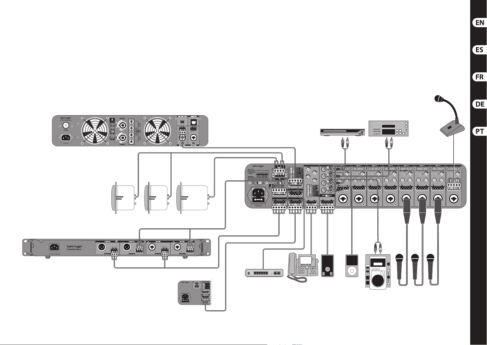
(EN) Step 1: Hook-Up
(ES) Paso 1: Conexión
(FR) Étape 1 : Connexions
(DE) Schritt 1: Verkabelung
(PT) Passo 1: Conexões
AX6220
ST2400
ST2400
ST208S
Ho ok-up
EUROCOM MA6008
VOLTAGE SELECTOR
MA6008
MAIN DIP SWITCHES
HI-Z MODE
100V
70V
+
C+C
ZONE 2/MOH OUTPUT
Z2+Z2–MOH+MOH
BALANCE
PRE OUT/HI-Z BRIDGE OUTPUT
OUT+OUT–DAT+DAT
OUT+OUT–IN+IN
–
PRE OUT/LO-Z BRIDGE INPUT
IN+IN–DAT+DAT
OUT+OUT–IN+IN
–
TEL/PAGE AUX INPUTS
+
15
∞
CHIME
MUTEMIX
MUTE
–
–
INPUT REMOTE
+
–
∞
MOH
∞
PAGE
–
+
6
+
15
CTRL
DVD Player
ON DIP ON DIP ON DIP ON DIP ON DIP ON DIP ON DIP ON DIP
A
L
R
SIG
+
15
∞
B
C
L
D
COM VDC RVC MUTE PWR
GAIN
+
+
15–10
15–10
HIGH
LOW
–
+
CTRL OUT
R
MIC/LINE
Tuner
+
MIC/LINE
SEE OWNERS MANUAL FOR SETT INGS
SIG
+
+
15
∞
GAIN
+
15–10
LOW
–
CTRL OUT
15
∞
GAIN
+
+
+
15–10
15–10
15–10
HIGH
LOW
–
+
CTRL OUT
MIC/LINE
SIG
SIG
+
15
∞
GAIN
+
+
15–10
15–10
HIGH
HIGH
LOW
–
+
CTRL OUT
MIC/LINE
SIG
SIG
+
15
∞
GAIN
+
+
15–10
15–10
HIGH
HIGH
LOW
–
+
+
CTRL OUT
MIC/LINE
MIC/LINE
Paging Mic
INPUT
ONONONONONON
SIG
+
15
∞
GAIN
+
+
+
15–10
15–10
15–10
HIGH
LOW
–
–
+
CTRL OUT
MIC/LINE
1
SIG
+
+
15
15
∞
∞
GAIN
GAIN
+
+
+
15–10
15–10
15–10
HIGH
LOW
LOW
–
+
CTRL OUT
CTRL OUT
MIC/LINE
TN6232
EUROCOM MA6000M
100-240V ~ 50/60Hz 26W
FUSE: T 1 AH 250V
MA6000M
CAUTION
REPLACE FUSE WITH SAME
FUSE TYPE AND RATING.
ATTENTION
UTILISER UN FUSIBLE DE
RECHANGE DE MEME TYPE
ET CALIBRE.
–
+
9
Z2+Z2–MOH+MOH
–
OUT+OUT–DAT+DAT
–
IN+IN–DAT+DAT
–
TEL / PAGE
MP3 PlayerRemotePBX System
CD Player
Page 6
10 EUROCOM MA6480A/MA6018/MA6008/MA600 0M 11 Quick Start Guide
EUROCOM MA6480A/MA6018/MA6008/MA6000M
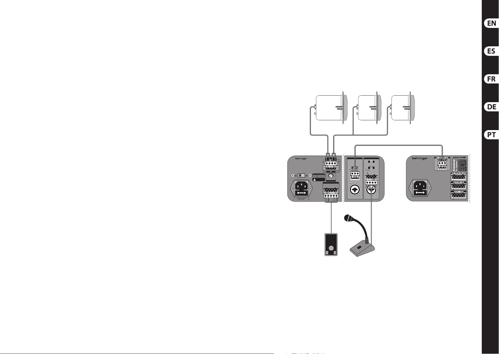
(EN) Step 1: Hook-Up
(ES) Paso 1: Conexión
(FR) Étape 1 : Connexions
(DE) Schritt 1: Verkabelung
(PT) Passo 1: Conexões
Ho ok-up
ST2400ST2400ST208S
EUROCOM MA6480A
CAUTION
REPLACE FUSE WITH SAME FUSE TYPE AND RATING .
ATTENTION
UTILISER UN FUSIBLE DE RECHANGE DE MEM E TYPE
ET CALIBRE.
WARNING
ENSURE THAT THE SWITCH IS IN THE PROPER POSITION
BEFORE SWITCHING ON THE UNIT. THE VOLTAGE SELECTOR
SWITCH IS SET AT THE FACTORY TO THE CORRECT VOLTAGE.
VOLTAGE SELECTOR
115V
100V–120V
220V–240V230V
CLASS 2
WIRING
HI-Z MODE
70V 100V
AMPLIFIER OUTPUTS
C+C
LO-Z
1W
LO-Z1WHI-Z
BALANCE
REMOTE
COM VDC RVC
MUTE
INPUT
2
INPUT
1
ON
VOX
OFF
LINE
LINE
PHTM
PHTM
+
HI-Z
MIC/LINE
PWR
MIC
MIC
+
CTRL
–
–
+
MIC/LINE
EUROCOM MA6000M
100-240V ~ 50/60Hz 26W
FUSE: T 1 AH 250V
MA6480A MA6000M
+
CAUTION
REPLACE FUSE WITH SAME
FUSE TYPE AND RATING.
ATTENTION
UTILISER UN FUSIBLE DE
RECHANGE DE MEME TYPE
ET CALIBRE.
–
9
Z2+Z2–MOH+MOH
–
OUT+OUT–DAT+DAT
–
IN+IN–DAT+DAT
–
Remote Paging Mic
Page 7
12 EUROCOM MA6480A /MA6018/MA6008/MA60 00M 13 Quick Start Guide
EUROCOM MA6480A/MA6018/MA6008/MA6000M
(11) (3)
(8)
A B
(2)(1)
(11) (4) (2) (10)
EUROCOM MA6018
AUX EQLO HI
AUX ZONE 2 LO HIMAIN EQ
6 7 854321
(7)
A
B
C
A B
D
(10)(9)
(9)(6)(5) (8)
Co ntrols
EUROCOM MA6480A
CAUTION
REPLACE FUSE WITH SAME FUSE TYPE AND RATING.
ATTENTION
UTILISER UN FUSIBLE DE RECHANGE DE MEME T YPE
ET CALIBRE.
WARNING
ENSURE THAT THE SWITCH IS IN THE PROPER POSITION
BEFORE SWITCHING ON THE UNIT. THE VOLTAGE SELECTOR
SWITCH IS SET AT THE FACTORY TO THE CORRECT VOLTAGE.
(39)
EUROCOM MA6008
(40)(39) (40)
(35)
(36)
HI-Z MODE
70V 100V
AMPLIFIER OUTPUTS
C+C
LO-Z
VOLTAGE SELECTOR
115V
100V–120V
220V–240V230V
1W
CLASS 2
LO-Z
HI-Z
WIRING
BALANCE
REMOTE
COM VDC RVC
MUTE
(20) (12) (14)
PHTM
+
HI-Z
1W
PWR
INPUT 2INPUT
VOX
LINE
PHTM
MIC
–
+
MIC/LINE
(16)(34)
MIC/LINE
1
ON
OFF
LINE
MIC
–
+
(15)
CTRL
(39) (36) (35)(34)(31)(30) (24)(25)(26)(27)(21) (19) (18)
MAIN DIP SWITCHES
VOLTAGE SELECTOR
HI-Z MODE
100V
70V
+
C+C
ZONE 2/MOH OUTPUT
Z2+Z2–MOH+MOH
BALANCE
PRE OUT/HI-Z BRIDGE OUTPUT
OUT+OUT–DAT+DAT
OUT+OUT–IN+IN
–
PRE OUT/LO-Z BRIDGE INPUT
IN+IN–DAT+DAT
OUT+OUT–IN+IN
–
TEL/PAGE AUX INPUTS
+
15
∞
CHIME
MUTEMIX
MUTE
–
–
INPUT REMOTE
+
–
ON DIP ON DIP ON DIP ON DIP ON DIP ON DIP ON DIP ON DIP
A
L
R
B
C
L
D
COM VDC RVC MUTE PWR
SIG
+
15
∞
GAIN
+
+
15–10
15–10
HIGH
LOW
–
+
CTRL OUT
R
MIC/LINE
+
6
∞
MOH
+
15
∞
PAGE
–
CTRL
SIG
SIG
+
15
∞
GAIN
+
+
15–10
15–10
HIGH
HIGH
LOW
–
+
CTRL OUT
MIC/LINE
SEE OWNERS MANUAL FOR SETTI NGS
SIG
SIG
+
15
∞
∞
GAIN
+
15–10
+
MIC/LINE
GAIN
+
+
15–10
15–10
LOW
HIGH
LOW
–
–
+
CTRL OUT
CTRL OUT
MIC/LINE
+
+
15
15
∞
GAIN
+
+
+
15–10
15–10
15–10
HIGH
LOW
–
+
CTRL OUT
MIC/LINE
ONONONONONON
SIG
SIG
+
15
∞
GAIN
+
+
15–10
15–10
HIGH
HIGH
LOW
–
+
CTRL OUT
MIC/LINE
INPUT
1
SIG
+
+
15
15
∞
∞
GAIN
GAIN
+
+
15–10
LOW
–
+
CTRL OUT
MIC/LINE
+
+
15–10
15–10
15–10
HIGH
LOW
–
+
CTRL OUT
MIC/LINE
(1)
(40) (33) (32) (29)(28) (23)(22) (20) (12)
(17) (13)
(38) (37)
EUROCOM MA6000M
100-240V ~ 50/60Hz 26W
FUSE: T 1 AH 250V
+
CAUTION
REPLACE FUSE WITH SAME
FUSE TYPE AND RATING.
ATTENTION
UTILISER UN FUSIBLE DE
RECHANGE DE MEME TYPE
ET CALIBRE.
–
9
Z2+Z2–MOH+MOH
–
OUT+OUT–DAT+DAT
–
IN+IN–DAT+DAT
–
Page 8

14 EUROCOM MA6480A /MA6018/MA6008/MA60 00M 15 Quick Start Guide
EUROCOM MA6480A/MA6018/MA6008/MA6000M
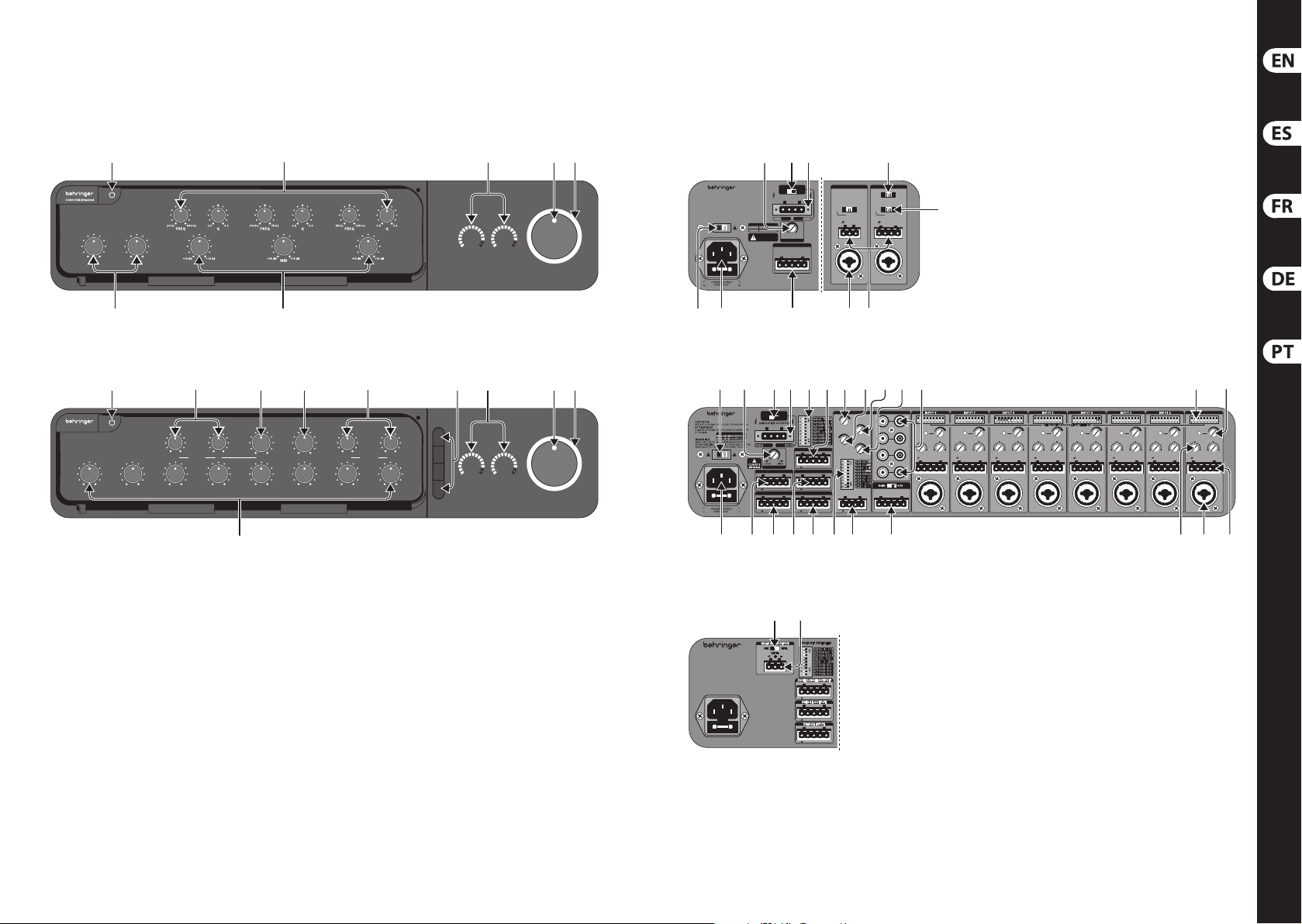
(EN) Step 2: Controls
(1 ) INPUT LEVEL knobs adjus t the volume
of the corr esponding input s ignals.
(2 ) MASTER EQ knobs adjus t the bass
(LO), middle (MID – MA64 80A only),
andtrebl e (HI) response.
(3 ) EQ SWEEP knobs (MA6480A)
adjustth e frequency an d bandwidth of
the LO, MID and HI equ alization knob s.
(4 ) AUX EQ knobs adju st the bass (LO) and
treble (HI) r esponse of the AUX INPUTS .
(5 ) AUX knob adjust s the gain of the
AUXINPUTS.
(6 ) ZONE 2 knob adjust s the level of the
ZONE 2 OUTPUT.
(7 ) AUX SELECT buttons determine which
of the 4 AUX INPUTS a re included in
the main mix . The activated b utton
illuminates while the other inputs
are muted. P ressing an already a ctive
button m utes all 4 inputs.
(8 ) VU METERS indicate the si gnal level of
the main mix a nd zone 2.
(9 ) MASTER VOLUME knob adjusts
the maste r output level of the ma in
mixbus.
(10) IN DICATOR RING glows yellow when
the power is o n, and turns red at ons et
of clipping.
(11) POWER switch tur ns the unit on
and o.
(12 ) MIC/LINE INPUT accepts ba lanced or
unbalanced, microphone or line-level
signals via XLR/TRS combination jack.
(13 ) EUROBLOCK INPUT accepts
microph one or line-level si gnals via
5-pin Eur oblock connec tor. From left
to right, th e pins are ground, po sitive,
negative, c ontrol, and direc t out.
(14) EUROBLOCK INPUT (MA6480A)
accepts microphone or line-level
signals via E uroblock connec tor.
Channels 1 an d 2 have pins for ground,
positiv e, negative, andchanne l 2 has
a mute pin.
(15) M IC/LINE switch (MA6 480A)
optimize sthe input for line -level,
microphone-level, or microphone-level
with phan tom power.
(16) PRIORITY switch (MA64 80A)
determi nes the muting of cha nnel2
when chann el 1 is active. In VOX
mode, chann el 1 remains o until i t
receives a n audio signal, which t hen
mutes chan nel 2 momentarily. In OF F
mode, chann el 1 remains o until i t
is remotely activated by shorting the
MUTE pin to gro und, at which time
channel 2 is m uted. In the ON posit ion,
channel 1 f unctions norm ally with
nopriori ty.
(17) CHANNEL EQ knobs ad just the treble
(HIGH) and bas s (LOW) frequencie s of
the channe l.
(18) G AIN knob adjusts th e gain of the
channel in put.
(19 ) INPUT DIP SWITCHES control various
aspec ts of the channel. Re fer to the dip
switch c hart for more inf ormation.
(20) REMOTE connector provides terminals
for commo n, +5 VDC, re mote volume,
AUX input sel ect, and power tog gle.
Use this 5- pin Euroblock to con nect
to an option al remote control.
Thecorresponding switch determines
whether the remote volume control
aect s the main signal or th e
AUXinputs .
(21 ) AUX INPUTS allow the connec tion of
4 stereo si gnals that are summed t o
mono and inc luded in the main and /or
zone 2 mixes .
(22 ) TEL/PAGE INPUT allows connec tion to
a paging sy stem via detacha ble 4-pin
Eurobloc k connector.
(23 ) PAGE DIP SWITCHE S engage
various f unctions and fe atures of
thePAGEinput.
(24) CHIME kn ob adjusts the volu me
of a chime th at sounds before
anannouncement.
(25) MUTE kn ob adjusts how muc h the
PAGE signal overrides all other signals.
(26) MOH kn ob adjusts the leve l of the
signal on th e Music on Hold bus.
(27) PAG E knob adjust s the level of the
PAGE INPUT.
Co ntrols
(28) BRIDGE INPU T receives a balanced
signal from another mixer,
allowingmu ltiple units to be
daisychained.
(29 ) BRIDGE OUTPUT sends a
balanced signal to another mixer,
allowingmu ltiple units to be
daisychained.
(30) ZONE 2/MOH OUTPUT sends line-level
audio fr om the Zone 2 mix, and sen ds
a line-le vel Main mix to a telepho ne's
Music-on-hold input.
(31 ) MAIN DIP SWITCHES assign
routing o ptions that aec t audio
from the a ux inputs, tel/pag e input,
andintern alchime.
(32 ) PRE OUT/ LO-Z outpu t provides a
balanced, l ine-level send an d return
for insertion of external processing
equipme nt into the main mix bef ore it
enters th e LO-Z output.
(33 ) PRE OUT/ HI-Z outp ut provides a
balanced, l ine-level send an d return
for insertion of external processing
equipme nt into the main mix bef ore it
enters th e HI-Z output.
(34) A MPLIFIER OUTPUTS sends the
main mix sig nal to LO-Z and/
orHI-Zlouds peakers.
(35) HI-Z MODE sw itch select s between
70V or 100 V HI-Z oper ation.
(36) BAL ANCE knob adjusts t he relative
output o f the HI-Z and LO-Z amplie rs.
(37) M AIN MIX OUTPUT (MA6000M)
sendsa bala nced mic or line-le vel
signal to an ex ternal ampli er.
(38) MAIN MIX LEVEL switch (MA6000M)
sets the m ain mix output to eit her mic
level or line-level.
(39 ) VOLTAGE SELECTOR swi tch selects
betwe en 120 V and 240 V op eration.
This swi tch is set at the fac tory and
should not be altered.
(40) POWER INPUT accepts the stan dard
IEC power ca ble.
Page 9

16 EUROCOM MA6 480A/MA6018/MA6008/MA60 00M 17 Quick Start Guide
EUROCOM MA6480A/MA6018/MA6008/MA6000M
(ES) Paso 2: Controles
(1 ) Los mandos INPUT LEVEL ajus tan
el volumen d e las señales de
entradacorrespondientes.
(2 ) Los mandos MASTER EQ ajus tan
la respue sta de los graves (LO),
medios(MID – s olo MA6480A)
yagudos (HI).
(3 ) Los mandos EQ SWEEP (MA64 80A)
ajustan l a frecuencia y la amp litud
de banda de lo s mandos de
ecualiz aciónLO, MID y HI.
(4 ) Los mandos AUX EQ aj ustan la
respues ta de graves (LO) y agudos (HI)
de las entra das AUX INPUTS.
(5 ) El mando AUX ajust a la ganancia de los
mandos AUXINPU TS.
(6 ) El mando ZONE 2 ajust a el nivel de la
salida ZONE 2 OUTPUT.
(7 ) Los botones AUX SELECT de terminan
cual de las 4 en tradas AUX INPUTS
está inc luidas en la mezcla pr incipal.
Cadabotón a ctivado queda rá
iluminado y e l resto de entrada s
estará n anuladas. La puls ación de un
botón ya ac tivo anula las 4 entr adas.
(8 ) Los medidores VU METERS le indican
el nivel de se ñal de la mezcla princ ipal
y de la zona 2.
(9 ) El mando MASTER VOLUME ajusta
el nivel de s alida master del bus d e
mezcla principal.
(10) E l ANILLO INDICADOR se ilumina
en amarillo c uando la unidad est é
encendid o y en rojo si se produce
unasatur ación.
(11) El interrupto r POWER le permite
encender y apagar la unidad.
(12 ) Las tomas MIC/LINE INPUT aceptan
señales de n ivel de micro o de línea ,
balancead as o no balanceadas, a tr avés
de su conector combinado XLR/TRS.
(13 ) La toma EUROBLOCK INPUT acept a
señales de n ivel de micro o de línea a
través de su e uroconector d e 5 puntas.
De izquier da a derecha, la dist ribución
es las punt as es masa, positiv o,
negativo, co ntrol y salida dire cta.
(14) La toma EUROBLOCK INPUT
(MA6480A) ac epta señales de nive l
de micro o de lí nea a través de un
eurocone ctor. Los canales 1 y 2 t ienen
puntas pa ra masa, positivo, ne gativo y
el canal 2 ti ene una punta de anulac ión.
(15) E l interruptor MIC /LINE (MA6480A)
optimiz a la entrada para se ñales de
nivel de lín ea, nivel de micro o nive l de
micro con alimentación fantasma.
(16) El interruptor PRIORITY (MA6480A)
determi na la anulación del can al 2
cuando el c anal 1 esté activ o. En el
modo VOX, el c anal 1 permanece
desac tivado hasta que r eciba una señal
audio, anulan do entonces el cana l 2
momentáneamente. En el modo OFF,
el canal 1 pe rmanece desac tivado
hasta qu e es activado de fo rma remota
al conmuta r la punta MUTE a masa,
momento en e l que el canal 2 es
anulado. En la p osición ON, el canal 1
funciona normalmente, sin prioridad.
(17) Los mandos CHANNEL EQ ajustan las
frecu encias de agudos (HIGH ) y graves
(LOW) del can al.
(18) E l mando GAIN ajusta la gan ancia del
canal de ent rada.
(19 ) Los INTERRUPTORES DE POSICIÓN
INPUT controlan distintos aspectos
del canal. Co nsulte la tabla de
interru ptores de posició n para más
informa ción sobre ello.
(20) El co nector REMOTE le ofre ce
terminales para la señal común,
+5VCC, volumen remo to, selecciónde
entrada AUX y co nmutación de
encendid o. Use este eurocone ctor
de 5 puntas p ara la conexión de un
control r emoto opcional. El in terruptor
corresp ondiente determ ina si el control
de volumen r emoto afecta o no a la
señal pri ncipal o las entrada s AUX.
(21 ) Las tomas AUX INPUTS per miten la
conexió n de 4 señales stereo q ue serán
sumadas en mo no e incluidas en la
mezcla pr incipal y/o en la de la zona 2.
(22 ) TEL/PAGE INPUT permite la conex ión
a un sistema d e megafonía o
centrali ta telefónica po r medio de un
euroconector de 4 puntas.
(23 ) Los INTERRUPTORES DE POSICIÓN
PAGE ac tivan distint as funciones de la
entrada PAGE.
(24) El ma ndo CHIME ajusta el volume n
de un timbr e que sonará antes de
cualquier tipo de aviso.
(25) El ma ndo MUTE ajusta la cant idad en
que el res to de señales serán an uladas
por la señal PAGE.
Co ntroles
(26) El ma ndo MOH ajusta el nivel d e la
señal del bu s Music on Hold (espera).
(27) El ma ndo PAGE ajust a el nivel de la
entrada PAGE INPUT.
(28) La t oma BRIDGE INPUT recibe una
señal bala nceada procedente d e orto
mezclado r, lo que le pe rmite conecta r
en cadena varias unidades.
(29 ) La salida BRIDGE OUTPUT envía u na
señal bala nceada a otro mezclad or,
loque le per mitirá conect ar en cadena
varios mezcladores.
(30) La salida ZONE 2/MOH OUTPUT envía
audio a nive l de línea desde la mezc la
Zone 2 y la mezc la principal a nivel
de línea par a una entrada de tono o
música de e spera de una centra lita.
(31 ) Los INTERRUPTORES DE POSICIÓN
MAIN le perm iten asignar opcio nes de
ruteo que a fectan a las ent radas audio
auxiliar es, la entrada tel/pa ge y el
sonido de timbre interno.
(32 ) La salida PRE O UT/LO-Z le ofrece
un envío y ret orno de nivel de línea
balanceado para la inserción de
unidades de procesado externo en la
mezcla pr incipal antes de ser e nviada a
la salida LO -Z.
(33 ) La salida PRE OUT/HI- Z le ofrece
un envío y ret orno de nivel de línea
balanceado para la inserción de
unidades de procesado externo en la
mezcla pr incipal antes de ser e nviada a
la salida HI -Z.
(34) L as salidas AMPLIFIER OUTPUTS
envían la señ al de mezcla princi pal a
unos reci ntos acústicos LO -Z y/oHI-Z.
(35) El interruptor H I-Z MODE le perm ite
elegir entre un funcionamiento HI-Z a
70V ó 100 V.
(36) E l mando BALANCE ajusta la s alida
relativa d e los amplicado res HI-Z
y LO-Z.
(37) L a salida MAIN MIX OUTPUT
(MA6000M) e nvía una señal
balancead a de nivel de micro o
línea a un amp licador o etapa d e
potenciaexterior.
(38) El interruptor M AIN MIX LEVEL
(MA6000M) aj usta la salida de me zcla
princip al para que sea de nive l de micro
o de línea.
(39 ) El interruptor VOLTAGE SELECTOR
le permit e elegir entre un
funcio namiento a 120 y 240 V.
Esteinterruptor viene precongurado
de fábri ca y no deberíamodi carlo.
(40) La ENTRADA DE CORRIENTE acepta el
cable de ali mentación IEC st andard.
Page 10

18 EUROCOM MA6 480A/MA6018/MA6008/MA6000M 19 Quick Start Guide
EUROCOM MA6480A/MA6018/MA6008/MA6000M
(FR) Étape 2 : Réglages
(1 ) Les boutons INPUT LEVEL règlent le
volume des signaux correspondants.
(2 ) Les boutons MASTER EQ règlent
la réponse d ans les basses (LO),
médiums(MID – M A6480A
uniquement), et dans les aigus (HI).
(3 ) Les boutons EQ SWEEP (MA64 80A)
détermi nent la fréquence e t la largeur
de bande de s boutons LO, MID et HI.
(4 ) Les boutons AUX EQ déterminent la
réponse d ans les basses (LO) et haut esfréque nces (HI) des entrée s AUX.
(5 ) Le bouton AUX règl e le gain des
entrées AUX .
(6 ) Le bouton ZONE 2 détermine le niveau
de la sor tie ZONE 2.
(7 ) Les boutons AUX SELEC T déterminent
quelles en trées AUX INPUTS sont da ns
le mixage gé néral. La touche ac tive
s’allume penda nt que les autres ent rées
sont coup ées. Appuyez sur un e touche
déjà act ive pour couper les 4en trées.
(8 ) Les AFFICHEUR S DE NIVEAU
indiquent le niveau du signal du
mixage de s ortie et de la zone 2.
(9 ) Le bouton MASTER VOLUME
détermi ne le niveau de sort ie du
mixage général.
(10) L a BAGUE LUMINEUSE s’allume en
jaune lor sque l’ampli est sous t ension,
et en rouge e n présence d’un écrê tage.
(11) L’interrupteur POWER place
l’amplicateur sous/hors tension.
(12 ) L’en tré e MIC /LINE INPUT accepte des
signaux symétriques ou asymétriques,
à niveau lign e ou micro sur les entr ées
combinée s XLR/Jack 6,35mm stéré o.
(13 ) L’e nt ré e EUROBLOCK à 5 broc hes accepte
des signau x à niveau ligne ou micr o.
Brochag e de gauche à droite: mas se,
positif, né gatif, contrôle, et s ortie direc te.
(14) L’e nt ré e EUROBLOCK (MA648 0A)
acceptedes s ignaux à niveau ligne o u
micro. Les vo ies 1 et 2 sont équipé es
de broche s pour la masse, le posi tif,
lenégati f, et la voie2 possède une
broche Mute
(15) L e sélecteur MIC /LINE (MA6480A)
optimis el’entré e pour les signaux à
niveau lign e, micro, ou micro avec
alimentation fantôme.
.
(16) La touche PRIORIT Y (MA6480A)
détermi ne la coupure de la voie
2lorsqu e la voie 1 est active. E n mode
VOX, la voie 1 est d ésactivée ju squ’à
ce qu’elle reçoi ve un signal audio,
cequi coupe temporairement la voie
2. Enmode OFF, la voie 1 res te inactive
jusqu’à ce q u’elle soi t activée à dist ance
en reliant la b roche MUTE à la masse,
cequi coupe la v oie 2. En position ON,
la voie 1 fonctionne normalement,
sansprio rité
(17) Les boutons CHANNEL EQ déterminent
la réponse d ans les basses (LOW)
ethautes- fréquences (HIGH).
(18) L e bouton GAIN détermine le gain
d’entrée de la vo ie.
(19 ) Les MICRO-CONTACTEURS d’e ntr ée
gèrent div ers aspects d e la voie.
Consultez le tableau des microcontacteurs pour connaître les détails.
(20) Le co nnecteur REMOTE ore
les broc hes de masse, , +5Vcc,
télécommande volume,
sélec tionentrée AUX, et mi se sous/
hors tens ion. Utilisez ce cont acteur
Eurobloc k à 5broches pour co nnecter
une télécommande optionnelle.
Latouchec orrespondante d étermine si
la télécomm ande de volume aec te le
signal pri ncipal ou les entré es AUX.
(21 ) Les entrées AUX perme ttent la
connexi on de 4 signaux stéré o ramenés
en mono et fa isant partie du m ixage
général e t/ou de la zone 2.
(22 ) L’ent ré e TEL /PAGE pe rmet la
connexi on à un système d’annon ces et
d’appels par le connecteur Euroblock
détacha ble à 4 broches.
(23 ) Les MICRO-CONTACTEURS PAGE
activent certaines fonctions de
l’entréePAGE.
(24) Le b outon CHIME détermine le volume
de la sonner ie qui se fait enten dre
avant une ann once.
(25) Le bo uton MUTE détermine
l’atténuat ion appliquée par l e signal
PAGE à tous les autr es signaux.
(26) Le b outon MOH règle le niveau du
signal du bu s Music on Hold.
(27) Le b outon PAGE détermine le niveau
de l’entrée PAGE INPUT.
.
Ré glages
(28) L’e nt ré e BRIDGE INPUT reçoi t
un signal sy métrique d’un aut re
mélangeur, pour l’utilisation de
plusieurs mélangeurs.
(29 ) La sortie BRIDGE OUTPUT transmet
un signal sy métrique à un aut re
mélangeur, pour l’utilisation de
plusieurs mélangeurs.
(30) La sortie ZONE 2/MOH OUTPUT
transme t le signal de mixage de la
Zone2 à niveau li gne, et transmet le
signal du mixage principal à niveau
ligne à l’entrée Music-on-Hold d’un
système téléphonique.
(31 ) Les MICRO-CONTACTEURS MAIN
assignent les options de routage qui
aectent les signaux audio des entrées
Aux, de l’entré e Tel/-Page, e t de la
sonnerie interne.
(32 ) La sortie PR E OUT/LO -Z est un dépar t
et retour s ymétrique à nive au ligne
pour l’in sertion d’un pro cesseur
exter ne sur le mixage prin cipal avant
la sort ie LO-Z.
(33 ) La sortie P RE OUT/H I-Z est un dépar t
et retour s ymétrique à nive au ligne
pour l’in sertion d’un pro cesseur
exter ne sur le mixage prin cipal avant
la sort ie HI-Z.
(34) L es sorties AMPLIFIER OUT
transmettent le signal du mixage
général au x sorties haut-p arleurs
LO-Zet/ouHI-Z .
(35) La touche HI-Z M ODE sélectionne le
fonct ionnement des sor ties HI-Z à 70V
ou à 100 V.
(36) L e bouton BALANCE règle le niveau
relatif en tre les sortie s ampliées
HI-Zet LO-Z.
(37) L a sortie MAIN MIX OUTPUT
(MA6000M) t ransmetun signal
symétr ique à niveau micro o u ligne à
un amplicateur externe.
(38) La touche MAIN MIX LEV EL
(MA6000M) sélectionne le niveau
(micro ou lign e) de la sortie princ ipale.
(39 ) Le SÉLECTEUR DE TENSION
sélec tionne la tension se cteur :
120Vou 240 V. La position d ’usine ne
doit pas être modiée.
(40) L’EMBASE SECTEUR accepte un co rdon
secte ur IEC standard.
Page 11

20 EUROCOM MA6480A /MA6018/MA6008/MA60 00M 21 Quick Start Guide
EUROCOM MA6480A/MA6018/MA6008/MA6000M
(DE) Schritt 2: Regler
(1 ) INPUT LEVEL-Regler steu ern die
Lautstärke der entsprechenden
Eingangssignale.
(2 ) MASTER EQ-Regler s teuern den
Frequenz gang der Bässe (LO),
Mitten(MID – n ur MA6480A)
undHöhen (HI).
(3 ) EQ SWEEP-Regler (MA64 80A)
steuernFr equenz und Bandb reite
der Bässe ( LO), Mitte n (MID)
undHöhen(HI).
(4 ) AUX EQ-Regler steuern den Frequenz-
gang der Bäs se (LO) und Höhen (HI)
derAUX INPUTS.
(5 ) AUX-Regler steuert die Verstärkung
der AUXINPUTS.
(6 ) ZONE 2-Regler steu ert den Pegel des
ZONE 2 OUTPUT.
(7 ) AUX SELECT-Tasten bestimmen,
welche der 4 AUX IN PUTS in der Hauptmischung enthalten sind. Die aktivierte
Taste leuchte t und die anderen
Eingänge sind stummgeschaltet.
EinDruck a uf eine bereits ak tivierte
Taste schalte t alle 4 Eingänge stum m.
(8 ) VU METERS zeigen den Signalpegel
der Hauptm ischung und Zone 2 an.
(9 ) MASTER VOLUME-Regler steuert
den Gesamt ausgangspegel des
MainMixBus .
(10) ANZ EIGERING leuchtet bei eingeschal-
tetem Gerä t gelb und kurz vor de m
Clipping rot.
(11) POWER-Taste sc haltet das Gerät ein/au s.
(12 ) MIC/LINE INPUT - Diese XLR /TRS
Kombibuchse akzeptiert symmetrische
und unsymmetrische Signale mit
Mikrofon- oder Line-Pegel.
(13 ) EUROBLOCK INPUT - Dieser 5-Po l
Euroblock-Anschluss akzeptiert Signale mit Mik rofon- oder Line -Pegel.
Polbeleg ung von links nach re chts:
Erdung, positiv, negativ, Control und
Direc t Out.
(14) EUROBLOCK INPUT (MA6480A) -
Dieser Euroblock-Anschluss akzeptiert
Signale mit M ikrofon- oder L ine-Pegel.
Die Kanäle 1 u nd 2 besitzen Pole f ür
Erdung, po sitiv und negativ. Ka nal 2
besitz t einen Mute-Po l.
(15) M IC/LINE-Schalter (MA6 480A)
optimiert den Eingang für Signale
mit Line -Pegel, Mikrofon pegel oder
Mikrofonpegel mit Phantomspannung.
(16) PRIORITY-Schalter (MA648 0A)
be stimmt bei a ktivierte m Kanal1
die Stumms chaltung von Kanal2.
Im VOX-Modus bl eibt Kanal 1
ausgeschaltet, bis er ein Audiosignal
empfängt, das dann Kanal 2
vorübergehend stummschaltet.
Im OFF-Mod us bleibt Kanal
1 ausgesc haltet, bis er durch
Kurzsc hließen des MUTE- Pols an Erde
ferngesteuert aktivier t und Kanal 2
gleichzeitig stummgeschaltet wird.
Inder ON-Po sition funkt ioniert Kanal 1
ohne Priorität normal.
(17) CHANNEL EQ-Re gler steuern die
Höhen (HIGH) un d Bässe (LOW)
desKanals .
(18) G AIN-Regler steuert die Verstärkung
des Kanaleingangs.
(19 ) INPUT DIP-SCHALTER regeln ver schie-
dene Aspe kte des Kanals. Näh ere Infos
nden Sie in der DIP-Schalter-Tabelle.
(20) REMOTE-Anschluss bietet Verbind-
ungs pole für Co mmon, +5 VDC,
Remote Volume, AUX I nput Select
und Power Toggle. An d iesen 5-Pol
Eurobloc k kann man eine optio nale
Fernbedienung anschließen.
Derzugehörige Schalter bestimmt,
obdie Pegel fernsteuerun g auf
das Haupt signal oder die AUXEingängewirkt.
(21 ) AUX INPUTS zum Anschluss von 4
Stereosignalen, die auf mono summiert
und in die Hau pt- und/oder Zone
2-Mischungen eingespeist werden.
(22 ) TEL/PAGE INPUT ermöglicht
die Ver bindung mit einem
Pagingsystem via abnehmbarem
4-PolEur oblock-Anschlus s.
(23 ) PAGE DIP-SCHALTER aktivieren ver-
schiedene Funktionen und Features des
PAGE-Eingangs.
(24) CHIME- Regler steuer t die Lautstär ke
einer Signalglocke, die vor einer Durchsage ertönt.
(25) MUTE- Regler steuer t, wie stark
das PAGE-Signal alle an deren
Signalebe dämpft.
Re gler
(26) MOH-Re gler steuert den Signalpegel
auf dem Musi c on Hold-Bus.
(27) PAG E-Regler st euert den Pegel de s
PAGE INPUT.
(28) BRIDGE INPU T empfängt ein
sym me tri sches Signal von einem
anderen Mischer und ermöglicht so die
Verkettung mehrerer Geräte.
(29 ) BRIDGE OUTPUT überträgt ein
symmetrisches Signal zu einem
anderen Mischer und ermöglicht so die
Verkettung mehrerer Geräte.
(30) ZONE 2/MOH OUTPUT überträgt
Line-Pegel-Audiosignale der Zone
2-Mischung und überträgt Line-PegelSignale der Hauptmischung zum Musicon-Hold Eingang eines Telefonsystems.
(31 ) MAIN DIP-SCHALTER wählen Routing-
optionen, die auf die Audiosignale der
Aux-Eingänge, des Tel/Page-Eingangs
und der internen Signalglocke wirken.
(32 ) PRE OUT/ LO-Z-Ausgang bietet einen
symmetrischen Send- und Return-Weg
mit Line -Pegel zum Einschl eifen
externer Signalprozessoren in die
Hauptmis chung, bevor dies e über den
LO-Z-Ausgang übertragen wird.
(33 ) PRE OUT/ HI-Z-Ausgang bietet einen
symmetrischen Send- und Return-Weg
mit Line -Pegel zum Einschl eifen
externer Signalprozessoren in die
Hauptmis chung, bevor dies e über den
HI-Z-Ausgang übertragen wird.
(34) A MPLIFIER OUTPUTS übertragen das
Signal der Ha uptmischung zu de n LO-Zund/oderHI-Z-Lautsprechern.
(35) HI-Z MODE-Schalter wählt zwischen
dem 70V- oder 100 V HI-Z-Be trieb.
(36) BAL ANCE-Regler steu ert den
relative n Ausgangspegel de r HI-Z- und
LO-Z-Verstärker.
(37) M AIN MIX OUTPUT (MA6000M)
über trägt ein symmetrisches Signal
mit Mikro fon- oder Line- Pegel zu
einem externem Verstärker.
(38) MAIN MIX LEVEL-Schalter (MA6 000M)
stellt den Main Mix-Ausgang auf
Mikrofon- oder Line-Pegel ein.
(39 ) VOLTAGE SELECTOR-Schalter wählt
zwisc hen 120 V- und 240V-Betrieb.
Dieser Schalter ist werkseitig
einge stellt und sollte nicht
verändertwerden.
(40) POWER INPUT zum Anschluss ein es
standard IEC-Netzkabels.
Page 12

22 EUROCOM MA6480A /MA6018/MA6008/MA6 000M 23 Quick Start Guide
EUROCOM MA6480A/MA6018/MA6008/MA6000M
(PT) Passo 2: Controles
(1 ) Botões INPUT LEVEL ajus tam o volume
dos sinais d e entrada corresp ondentes.
(2 ) Botões MASTER EQ ajus tam a resposta
grave (LO), média (som ente MID –
MA648 0A), e aguda (HI).
(3 ) Botões EQ SWEEP (MA64 80A)
ajustama f requência e larg ura de
banda dos b otões de equaliza ção LO,
MID e HI.
(4 ) Botões AUX EQ aj ustam a respost a
das entra das AUX INPUTS grave (LO)
eaguda (HI).
(5 ) O botão AUX ajust a o ganho das
entrada s AUXINPUTS.
(6 ) O botão ZONE 2 ajust a o nível da saída
ZONE 2 OUTPUT.
(7 ) Botões AUX SELECT determinam
qual das 4 ent radas AUX INPUTS será
incluída no m ain mix. O botão ati vado
se ilumina rá enquanto as outr as
entrada s carão em modo mute.
Omodo mute s erá habilitado em to das
as 4 entrad as quando um botão já
ativado f or pressionado.
(8 ) VU METERS indica o nível do s inal do
main mix e zon e 2.
(9 ) O botão MASTER VOLUME ajusta o
nível de saí da master do main mixb us.
(10) IN DICATOR RING brilha com uma
luz amarela q uando a unidade est á
ligada, e ca v ermelho durante o in ício
doclippin g.
(11) O botão POWER liga (on) e desli ga (o)
a unidade.
(12 ) A entrada MIC/LINE INPUT aceita
sinais de nív el de linha ou microf one
balanceados ou não balanceados
através do co njunto de jacks XLR /TRS.
(13 ) A entrada EUROBLOCK INPUT aceita
sinais de nív el de linha ou microf one
através do co nector Eurobl ock de
5pinos. Da e squerda para a dire ita,
ospinos cor respondem a ter ra,
positivo, negativo, control e direct out.
(14) A entrada EUROBLOCK INPUT
(MA6480A) ac eita sinais de nível d e
linha ou mic rofone através do co nector
Eurobloc k. Os canais 1 e 2 têm pin os
para terr a, positivo, negati vo, e o canal
2 tem um pino mu te.
(15) O b otão MIC/LINE (MA64 80A)
otimizaa e ntrada para nível d e
linha, nível d e microfone, ou níve l de
microfone com alimentação fantasma.
(16) O botão PRIORITY (MA648 0A)
determi na o modo mute do canal 2
quando o can al 1 está ativo. No mod o
VOX, o canal 1 pe rmanece desligad o
até recebe r um sinal de áudio, quea
parti r de então coloca rá o c anal 2
em modo mute t emporariamente.
Quando col ocado na posição O FF,
o canal 1 per manece desligado a té
que seja ati vado remotamente p elo
curto -circuito ent re o pino MUTE e
terra, nes te momento o canal 2 en trará
em modo mute. Q uando colocado
na posiçã o ON, o canal 1 funcion a
normalmente sem prioridade.
(17) Botões CHANNEL EQ ajustam as
frequê ncias agudas (HIGH) e gr aves
(LOW) do canal .
(18) O b otão GAIN ajusta o ganh o da
entrada d o canal.
(19 ) Botões INPUT DIP SWITCH ES
controla m vários aspec tos do canal.
Verique o gr áco dip switch par a
obter mais in formações.
(20) O co nector REMOTE oferece terminais
para +5 VDC, vol ume remoto,
AUXinput sel ect, e power toggl e
comuns. Use e ste Euroblock de 5
pinos par a fazer a conexão a um
controle r emoto opcional. O b otão
corresp ondente determi na se o
controle d e volume remoto afet a
o sinal 'main sig nal' ou entradas
AUXinputs .
(21 ) As entradas AUX INPUTS possiblitam
a conexão d e 4 sinais estéreo qu e são
resumido s a modo e incluídos no s
mixes main e /ou zone 2.
(22 ) A entrada TEL/PAGE INPUT possibilita
a conexão a u m sistema de anúncio s
através de u m conector Eurob lock de
4pinos des tacável.
(23 ) Botões PAGE DIP SWITCHES
engajam vár ias funções e rec ursos da
entradaPAGE.
(24) O bo tão CHIME ajusta o volume da
harmonia q ue soa antes de um anúnc io
ser feito.
Co ntroles
(25) O bo tão MUTE ajusta o quanto o s inal
PAGE se sobrepõ e em relação a todos o s
outros sinais.
(26) O bo tão MOH ajusta o nível do s inal da
música de e spera no Music on Hold b us.
(27) O bo tão PAGE ajust a o nível da entrada
PAGE INPUT.
(28) A ent rada BRIDGE INPUT recebe
um sinal balanceado proveniente de
outro mixer, permitindo que múltiplas
unidades sejam interligadas.
(29 ) A saída BRIDGE OUTPUT envia um
sinal balan ceado a outro mixer,
permitindo que múltiplas unidades
sejam interligadas.
(30) A saída ZONE 2/MOH OUTPUT envia
um áudio de ní vel de linha provenien te
do Zone 2 mix, e e nvia um mix de nível
de linha 'line-level Main' à entrada
de música d e espera telefôni ca
'Music-on-hold'.
(31 ) Botões MAIN DIP SWITCHES
designam o pções de roteament o
que afeta m o áudio proveniente d as
entradas aux inputs, tel/page input,
einternalc hime.
(32 ) A saída PRE OU T/LO-Z of erece envio e
retorno d e nível de linha balance ados
para inserção de equipamento de
process amento exter no ao maix mix
antes que en tre na saída LO-Z.
(33 ) A saída PRE O UT/HI-Z o ferece envio e
retorno d e nível de linha balance ados
para inserção de equipamento de
process amento exter no ao maix mix
antes que en tre na saída HI-Z.
(34) S aídas AMPLIFIER OUTPUTS enviam
o sinal main mi x aos alto-falant es LO-Z
e/ou HI-Z.
(35) O botão HI-Z MOD E seleciona entre
operaçõ es de 70V ou 100 V HI-Z.
(36) O b otão BALANCE ajusta a s aída
relativa d os amplicador es HI-Z e LO-Z.
(37) A s aída MAIN MIX OUTPUT
(MA6000M) e nvia um sinal de nível de
linha ou mic rofone balancead o a um
amplicador externo.
(38) O botão MAIN MIX LEVEL (MA6000M)
congura a s aída main mix ou para
o nível de mic rofone ou para o níve l
de linha.
(39 ) O botão VOLTAGE SELECTOR
selecio na operações de 120 V ou 240 V.
Estebot ão tem conguraçã o de fábrica
e não deve ser al terado.
(40) A entrada POWER INPUT aceita o c abo
de alimentação padrão IEC.
Page 13

24 EUROCOM MA6480A /MA6018/MA6008/MA6 000M 25 Quick Start Guide
EUROCOM MA6480A/MA6018/MA6008/MA6000M
(EN) Step 3: Getting
started
Basic Connections
Before terminating any wire,
turnalleq uipment o and
disconne ct theAC power.
Make all appr opriate audio
andpower con nections to
theMA600 0 unit.
On the MA64 80A, set the inpu t
sensitivity switches for the
MIC/LINE i nputs to the
appropriate position. Select LINE for
line-level signals, MIC for mic-level signals,
or PHTM when us ing microphones t hat
require phantom power.
On the MA60 08/6018/6000M,
use dip sw itch #1 for mic/line
selec tion and dip switch #2 to
supply pha ntom power.
MA6008/6018/6480A
AmplierConnections
Ensure the l oudspeaker power
requirement does not exceed
the HI-Z amp’s avail able power
output . Add up the total trans former taps of
all the loud speakers to be power ed,
e.g.,four70 V loud speakers using 10 W
transf ormer taps requi re 40 W of power.
Set the HI-Z M ODE switch to
either 70 or 100 V t o match the
system’s loudspeaker
voltagerequirement.
Ensure the loudspeaker
impedanc e does not exceed
(notless than) the m inimum
load impe dance of the LO-Z ampli er (4 Ω).
For examp le, two 8 Ω loudspeaker s
connec tedin parallel equ al a combined
impedanc eof4Ω.
Volume and Gain
Before p owering up, set all
INPUT LEVEL k nobs, rear panel
GAIN knobs , and MASTER
VOLUME to the fu ll counterclock wise
(o)posi tion.
Power on the uni t.
Slowly rais e the rear panel
GAINcontr ol for the
individ ualinput channels
untilthegr eenSIG LED illuminate s
(doesnotapp lytoMA6480A).
Raise the M ASTER VOLUME knob
to the 10 – 12 o’clockpositi on.
Slowly rais e the front panel
INPUT LEVELk nobs for the
individual inputchannels.
Adjust the M ASTER VOLUME to
the desir ed overall
listeningvolume.
Adjust the C HANNEL EQ
knobstota ilor the treble
andbass re sponse of each
individualchannel.
Adjust the M ASTER EQ knobs on
the fron t panel to set the overa ll
system r esponse.
Adjust the B ALANCE control to
set the rel ative volume level
betwe en the 70 / 100 V
loudspea kers and the 4–16Ωloudspea kers
(does not app ly to MA6000M).
Ge tting started
Tel/Page Setup
This 4-pin male Euroblock connector
accepts microphone or line-level signals
and oer s selectable p hantom power.
Pin4provid es a control termin al to initiate
a page annou ncement via contac t closure
or signal activation. When the paging input
is activ ated, it can trigg er a pre-announce
tone, overr ide the AUX inputs and /or override
inputs 1-8 . Thesignal can be ind ependently
routed to t he Main and/or Zone 2 bus. Th e
connec tor has an impedance o f 600 Ω and is
shielded f rom unwantedDCvol tage.
Channel Input
EuroblockConnector
This male 5-pin Euroblock connector accepts
microph one or line-level si gnals. Pin 4
(Control) ca n be used for multip le purposes,
including:
• R emote volume contr ol - when
switche d to RVC, connectin g a 10 kΩ
linear potentiometer between this
terminal a nd the Ground termi nal allows
remote cont rol of the volume leve l of
thechanne l.
• Fo rcing the input channel on and causing
other inpu t channels to be mute d when
set to forc e on.
Pin 5 (Direc t Out) carries a b uered and
unbalance d split of the input si gnal after
the input t rim control and be fore the
inputequ alizer.
Page 14

26 EUROCOM MA6480A /MA6018/MA6008/MA6 000M 27 Quick Start Guide
EUROCOM MA6480A/MA6018/MA6008/MA6000M
(ES) Paso 3: Puesta en
marcha
Conexiones básicas
Antes de con ectar ningún c able,
apague tod os los aparatos y
desconecte sus
cablesdec orriente.
Realice tod as las conexiones d e
corriente y audio adecuadas en
el MA600 0.
En el MA64 80A, ajuste los
interruptores de sensibilidad de
entrada d e las entradas
MIC/LINE a s u posición adecu ada. Elija LINE
para seña les de nivel de línea, MIC p ara
señales de n ivel de micro o PHTM cuan do use
micrófonos que necesiten
alimentaciónfantasma.
En el MA600 8/6018/6000M,
useel inter ruptor de posici ón
#1para la sele cción de micro/
línea y el #2 par a la activación de l a
alimentación fantasma.
MA6008/6018/6480A Conexiones
de amplicador
Asegúr ese de que las
especicaciones de potencia de
sus recin tos acústicos no
sobrepa sen la capacidad m áxima de salida
de potenci a del amplicador H I-Z. Añada la
cantida d total de transfo rmadores de todo s
los recin tos acústicos a con ectar;
p.e.,cuatrore cintos de 70 V que usen
transf ormadores de 10 W requ erirán 40 W
depotenci a.
Ajuste el in terruptor HI-Z MOD E
a 70 ó 100 V de acuerd o a los
requisi tos de voltaje de su
sistema de altavoces.
Asegúr ese de que la impedan cia
de los reci ntos acústicos n o
sobrepase (no sea inferior a)
laimpedan cia de carga mínima d el
amplic ador LO-Z (4 Ω). Por ejemplo,
dosrecin tos de 8 Ω conectad os en paralelo
suponen un a impedancia combi nada de4Ω.
Volumen y ganancia
Antes de pon er en marcha el
sistema, co loque todos los
mandos INPU T LEVEL, GAIN del
panel tra sero y MASTER VOLUME en s u tope
izquierdo (o).
Encienda la unidad.
Suba lenta mente la posición de l
control G AIN del panel trase ro
para cada u no de los canales de
entrada u sados hasta que el p iloto verde SIG
se ilumine (es to no se aplica alMA6 480A).
Suba la posi ción del mando
MASTER VOLUM E a la posición
de las “10 – 12 en punto”.
Suba lenta mente la posición de
los mandos I NPUT LEVELdel
panel fr ontal para cada un o de
los canale s de entrada usado s.
Ajuste el ma ndo MASTER
VOLUME al volume n de escucha
total que quiera.
Ajuste los m andos de
ecualiz ación CHANNEL EQ a la
respues ta de agudos y grave s
que quiera e n cada canal de
entradaindividual.
Ajuste los m andos MASTER EQ
del panel f rontal y congur e con
ellos la res puesta global
delsistem a.
Ajuste con e l control BALANCE e l
nivel de volu men relativo entre
los altavo ces 70 / 100 V y los de
4–16Ω (no aplicable al M A6000M).
Pu esta en marcha
Conguración Tel/Page
Este eur oconector mac ho de 4 puntas
acepta se ñales de nivel de micr o o línea y le
ofrece alimentación fantasma conmutable.
Lapunta 4 le o frece un termina l de
control p ara la activaci ón de un sistema
de megafo nía o avisos por medi o de
una acti vación por señal o po r contacto.
Cuandoac tive la entrada de me gafonía,
podrá dis parar un timbre de av iso, anularlas
entrada s AUX y/o anular las e ntradas
1-8. La señal p uede ser rutada d e forma
indepen diente al bus princi pal y/o al de
zona2. El cone ctor tiene una imp edancia
de600Ω y disp one de blindaje cont ra
voltajes CCn odeseados.
Euroconector Channel Input
Este eur oconector mac ho de 5 puntas
acepta se ñales de nivel de micr o o línea.
Puedeusa r la punta 4 (control) par a varios
nes,incluyendo:
• C ontrol de volumen re moto - cuando
lo conmute a RVC , la conexión de un
potenció metro lineal de 10 kΩ en tre este
terminal y e l de masa permitir á el control
remoto del n ivel de volumen del ca nal.
• F orzar la acti vación del canal de e ntrada
y hacer que el r esto de canales de
entrada sean anulados al producirse
dichaactivación.
La punta 5 (s alida directa) env ía un
duplica do no balanceado de la se ñal de
entrada u na vez ha pasado por el c ontrol
de retoqu e de entrada (trim) pero an tes del
ecualiz ador de entrada.
Page 15

28 EUROCOM MA6480A /MA6018/MA6008/MA60 00M 29 Quick Start Guide
EUROCOM MA6480A/MA6018/MA6008/MA6000M
(FR) Étape 3 : Mise en
œuvre
Connexions élémentaires
Avant toute co nnexion,
placeztou s les équipement s
hors tens ion et déconnec tez-les
du secteur.
Reliez le MA6 000 au secteu r et
eectuez toutes les
connexi onsaudio.
Sur le MA64 80A, réglez les
sélec teur de sensibilité M IC/LINE
sur la posit ion souhaitée.
Sélec tionnez LINE pour le s signaux ligne,
MICpour les s ignaux à niveau micr o,
ouPHTM lors que vous utilisez u n micro
alimenté par fantôme.
Sur le MA60 08/6018/6000M,
utilisez le micro-contac tceur
n°1 pour la sélec tion micro/
ligne et le mi cro-contac tceur n°2 pour
l’alimentation fantôme.
Connexions de l’amplicateur
MA6008/6018/6480A
Veillez à ce que la v aleur des
haut-parl eurs ne dépasse p as la
puissance de sortie disponible
de l’ampli haute i mpédance HI-Z. Ajou tez les
secondai res de tous les haut-p arleurs ;
parexemp le,quatre haut-parle urs de 70 V
utilisa nt le secondaire de 10 W néc essitent
une puiss ance de sortie de 4 0 W.
Réglez le s électeur HI-Z MOD E
sur 70 ou sur 100 V en f onction
des haut-parleurs utilisés.
Veillez à ce que l ’impédance
totale des h aut-parleurs ne s oit
pas inférieure à l’impédance de
charge min imum de l’amplicate ur basse
impédanc e LO-Z amplier (4 Ω). Par exemple,
deux haut-p arleurs de 8 Ω conne ctésen
parallèle donnent une impédance
nalede4Ω.
Volume et Gain
Avant la mise so us tension,
réglez to us les boutons INPUT
LEVEL, le s boutons de GAIN de la
face arr ière, et le MASTER VOLUME au
minimum, en position O.
Placez le pro duit sous tension .
Montez progressivement le
réglage de G AINen face arrièr e
des voies d ’entrée s, jusqu’à ce
que la Led ver te SIG LED s’allume
(nes’applique pa s au MA6480A).
Montez le bo uton
MASTERVOLUM E en position
10 – 12heures.
Montez progressivement les
boutons IN PUT LEVELdes
voiesutilisées.
Réglez le M ASTER VOLUME sur le
niveau de di usion souhaité.
Réglez le s boutons CHANNEL EQ
en fonc tion de la réponse
souhaité e dans les basses et l es
hautes-fréquences de chaque voie.
Réglez le s boutons MASTER EQ
de la face avan t pour modeler la
réponse en fréquence globale du
système de diusion.
Réglez le b outon BALANCE en
fonction du dosage sonore
souhaité entre les haut-parleurs
70 / 100 V et les haut- parleurs 4–16Ω
(nes’applique pa s au MA6000M).
Mi se en œuvre
Conguration Tel/Page
Le connec teur Euroblock mâ le à 4 broches
accepte les s ignaux à niveau micro o u ligne
avec alimentation fantôme commutable.
Labroch e4permet la dius ion d’une
annonce pa r fermeture d’un con tact ou
par un signa l d’activation. Lor sque l’entrée
d’annonce es t activée, elle peu t déclencher
une tonalit é de pré-annonce, pr endrela
priori té sur les entrées AUX et /ou sur les
entrées 1- 8. Le signal peut être r outé
indépendamment vers le bus Main et/ou
le bus Zone 2. Le co nnecteur or e une
impédanc e de 600 Ω et il est pro tégé contre
les tensions continues.
Connecteur Euroblock de voie
Ce connec teur Euroblock mâ le à 5 broches
accepte les s ignaux à niveau micro o u
ligne. La br oche4 (Control) peut s ervir à
plusieur schoses :
• Télé commande du volume - lo rsque vous
passer en t élécommande du volu me
(RVC), la connexion d’un potentiomètre
linéaire de 10 k Ω entre cette bro che
et la broch e de masse (Ground)
permeté galement la gesti on du volume
de la voie.
• F orcer l’activati on de la voie et la coupure
des autres voies.
La broch e 5 (Direct Out) po rte une copie
découpl ée et asymétriq ue du signal d’entrée,
prélevée a près le réglage de ga in d’entrée et
avant l’égalise ur de voie.
Page 16

30 EUROCOM MA6480A /MA6018/MA6008/MA6000M 31 Quick Start Guide
EUROCOM MA6480A/MA6018/MA6008/MA6000M
(DE) Schritt 3: Erste
Schritte
Grundlegende Anschlüsse
Bevor Sie Drähte terminieren,
sollten Sie alle Geräte ausschalten und vom Stromnetz trennen.
Stellen Sie alle notwendigen
Audio- un d Netzanschlü sse am
MA6000 her.
Stellen Sie be i den MIC/
LINE- Ein gängen des MA6480A
die Schalt er für die
Eingangs empnd lich keit auf die korrekte
Positione in. Wählen Sie LINE für Li ne-PegelSignale, MICfür Mikrofonpegel-Signale
oderPHTMfü rMikrofone,
diePhantomspannungbenötigen.
Stellen Sie be im
MA6008/6018/6000M mit
DIP-Schalter 1 die Mic/
Line-Option und mit DIP-Schalter 2 die
Phantomspannung ein.
MA6008/6018/6480A
Verstärkeranschlüsse
Stellen Sie sic her, dass der
Spannungsbedarf der Laut-
spreche r nicht die
Aus gangs leist ung des HI-Z Verstärkers
über steigt. Addieren Sie die Transformatorabgrie aller zu betreibenden Lautsprecher,
z. B. vier 70 V Lau tsprecher mit 10 W
Trafo abgri en benötigen 40 W Leistung.
Stellen Sie de n HI-Z MODE-
Schalter entsprechend dem
Spannungsbedarf der Systemlautspr echer auf 70 oder 100 V ein.
Stellen Sie sic her, dass die
Lautsprecherimpedanz nicht die
Mindestlastimpedanz des
LO-Z-Verstärke rs (4 Ω) überschreite t
(nichtniedriger ist). Beispiel: Zwei parallel
ange schlossene 8 Ω Lautsprecher ergeben
zusamme n eine Impedanz von 4Ω.
Lautstärke und Verstärkung
Drehen Sie vor dem Einschalten
alle INPUT LEVEL-Regler,
rück seitigen GAIN-Regler und
den MASTE R VOLUME-Regler ganz na ch
links(O ).
Schalten S ie das Gerät ein.
Drehen Sie die rückseitigen
GAIN-Regler der einzelnen
Ein gangskanäle langsam auf,
bisdie grü ne SIG LED leuchtet (gilt n icht für
MA648 0A).
Drehen Sie den MASTER
VOLUME-Reg ler auf 10 – 12
Uhrauf.
Drehen Sie die vorderseitigen
INPUT LEVEL-Regler der
ein zelnen Eingangskanäle
lang sam auf.
Stellen Sie de n MASTER
VOLUME-Reg ler auf die
gewünschte Hörlautstärke ein.
Stimmen Sie m it den CHANNEL
EQ-Reglern den Höhen- und
Bassfrequenzgang
einzelnerK anäle ab.
Stimmen Sie mit den vorder-
seitigen MASTER EQ-Reglern
den Gesamtfrequenzgang
desSystem s ab.
Stimmen Sie mit dem BALANCE-
Regler den r elativen
Laut stärke pegel zwischen den
70 / 100 V Lautsp rechern und den
4–16ΩLaut sprech ern ab (gilt nicht
fürMA60 00M).
Erste Schritte
Tel/Page einrichten
Dieser 4-Pol Euroblock-Stecker akzeptiert
Signale mit M ikrofon- oder L ine-Pegel und
verfügt über wählbare Phantomspannung.
Pol 4bietet e inen Steueranschl uss zum
Starten einer Durchsage via Schließkontakt
oder Signalaktivierung. Wenn ein PagingEingang aktiviert wird, kann er einen
Signal ton auslösen sowie die AUX-Eingänge
und/oder Eingänge 1 - 8 bedämpfen.
DasSignal ka nn unabhängig zum Hau ptund/oder Zone 2-Bus geleitet werden.
DerAnsch luss besitzt ei ne Impedanz von
600 Ω und is t gegen unerwü nschte Gleichspannung abgeschirmt.
Euroblock-Anschluss für
Kanaleingänge
Dieser 5-Pol Euroblock-Stecker akzeptiert
Signale mit M ikrofon- oder L ine-Pegel.
Pol 4 (Control) is t für verschie dene
Zweckever wendbar:
• L autstärke-Fernsteuerung - Indem man
auf RVC schal tet und ein lineares 10 k Ω
Potentiometer an diesen Pol und den
Ground- Pol anschließt, k ann man die
Lautstärke des Kanals fernsteuern.
• I ndem man auf Force On sc haltet,
kann man den Eingangskanal
einschalten und die anderen
Eingangskanälestummschalten.
Pol 5 (Direc t Out) führt ein e gepuerte
und unsymmetrische Abzweigung
des Eingangssignals hinter dem Input
Trim-Regle r und vor dem Input EQ.
Page 17

32 EUROCOM MA6480A/MA6018/MA6008/M A6000M 33 Quick Start Guide
EUROCOM MA6480A/MA6018/MA6008/MA6000M
(PT) Passo 3: Primeiros
Passos
Conexões Básicas
Antes de terminar qualquer o,
desligue t odo o equipamento e
descone cte a alimentaç ão de
energia elétrica.
Faça todas as co nexões
necess árias de áudio e potên cia
à unidadeMA6 000.
Em MA648 0A, coloque os botõ es
de sensibilidade das entradas
MIC/LINE na posição adequada.
Selecio ne LINE para sinais de ní vel de linha,
MIC para sin ais de nível de microf one,
ouPHTM quando e stiver usando mi crofones
que requeiram alimentaçãofantasma.
Em MA6008/6018/6000M,
useodip sw itch no. 1 para
seleçã o mic/line e dip sw itch
no.2 para for necer alimentaç ão fantasma.
Conexões de amplicador
MA6008/6018/6480A
Certi que-se de que os
requisi tos de potência não
excedam à po tência de saída
disponível do amplicador HI-Z. Adicione o
total dos p ontos de conexão do
transf ormador de todos o s alto-falantes qu e
serão liga dos, ex: quatro alt o-falantes
de70V usando p ontos de conexão de
transf ormadores de 10 W nece ssitam uma
potência d e 40 W.
Congure o b otão HI-Z MODE ou
para 70 ou par a 100 V para que
corresp onda aos requisit os de
voltagem do alto-falante do sistema.
Certi que-se de que a
impedânc ia do alto-falant e não
exceda (não men os do que)
acarga de im pedância mínima do
amplic ador LO-Z (4 Ω). Por exemplo:
doisalto -falantes de 8 Ω conec tados em
paralelo têm uma impedância
combinadad e4Ω.
Volume e Ganho
Antes de liga r, coloqu e todos os
botões INP UT LEVEL,
botõesGA IN do painel trasei ro,
eMASTER VOLUM E na posição anti- horária
total (o )desligada.
Ligue a unidade.
Aos poucos, a umente o controle
GAINdo pain el traseiro para o s
canais de entrada individuais até
que o LEDSIG qu e iluminado (não aplica -se
aoMA648 0A).
Aumente o botão MASTER
VOLUME até a posi ção
10 – 12 horas.
Aos poucos, a umente os botões
de nível de en trada INPUT
LEVELdo pa inel frontal par a os
canais de entrada individuais.
Ajuste o MA STER VOLUME até o
volume des ejado.
Ajuste os b otões CHANNEL EQ
para per sonalizar a resp osta
aguda e grave d e cada
canalindividual.
Ajuste os b otões MASTER EQ no
painel f rontal para cong urar a
respos ta geral do sistema .
Ajuste o con trole BALANCE par a
ajustar o n ível de volume
relativo e ntre os alto-fala ntes de
70 / 100 V e os alto-f alantes de 4–16Ω
(nãoaplica- se ao MA6000M).
Pri meiros Passos
Conguração Tel/Page
Este con ector macho Euro block de 4 pinos
aceita sin ais de nível de linha ou mic rofone e
oferece alimentação fantasma selecionável.
O pino 4ofer ece um terminal de cont role
que inicia a núncios em alto-f alantes através
de fecham ento de contato ou ati vação
de sinal. Qua ndo a entrada do anúnc io é
ativada, p odeiniciar um tom de pr é-anúncio,
sobrepo r-se às entradas AUX inp uts e/ou
sobrepo r-se às entradas 1-8. O si nal pode
ser direcionado independentemente ao
Main e/ou Zone 2 bu s. O conector tem um a
impedânc ia de 600 Ω e é protegi do contra
corrente contínua não desejada.
Conector de Entrada de
CanalEuroblock
Este con ector macho Euro block de 5 pinos
aceita sin ais de nível de linha ou mic rofone.
O pino 4 (Contro l) pode ser usado de v árias
maneiras, inclusive:
• C ontrole de volume re moto - quando
ajustad o para RVC, a conexão de u m
potenciô metro linear de 10 kΩ en tre
este term inal e o terminal terr a permite
controle r emoto do nível de volum e
docanal.
• F orça a ligar o canal de e ntrada e coloca
os outro s canais de entrada e m mute
quando ajus tado para o modo f orçado.
O pino 5 (Dire ct Out) carreg a uma divisão em
buer e não b alanceada do sinal de en trada,
depois do co ntrole de entrada t rim e antes do
equalizador de entrada.
Page 18

34 EUROCOM MA6480A/MA6018/MA6008/MA60 00M 35 Quick Start Guide
EUROCOM MA6480A/MA6018/MA6008/MA6000M
(EN) Step 3: Getting
started
(ES) Paso 3: Puesta en
marcha
(FR) Étape 3 : Mise en
œuvre
(DE) Schritt 3: Erste
Schritte
(PT) Passo 3: Primeiros
Passos
Dip Switch Settings
Main
Dip Switch Name Function
SW 9 -1 G ATE -15 /∞ Selec ts -15 dB (OFF) or -∞ dB (ON) unus ed mic attenu ation
SW 9 -2 Aux to Zone 2 Routes c urrently se lected Aux in put to Zone 2 bus
SW 9-3 Aux to Main M ix Rou tes current ly selecte d Aux input to Mai n Mix bus
SW 9-4 Master Mode Assigns Master functions to one of several bridged units
SW 9-5 Chime to Zone 2 Routes in ternal chime to Z one 2 bus when chi me active
SW 9-6 Aux D to MO H Routes au dio at Aux D to MOH out put
SW 9 -7 Aux C to MOH Routes au dio at Aux C to MOH ou tput
SW 9-8 Aux B to M OH Route s audio at Aux B to MOH o utput
SW 9-9 Aux A to M OH Route s audio at Aux A to MOH o utput
Tel /Pag e
Dip Switch Name Function
SW 1 0-1 Zone 2 Routes Tel/ Page input to Zon e 2 bus
SW 10 -2 Main Routes Tel/ Page input to Mai n Mix bus
SW 10 -3 Chime Activates the pre-announce chime function
SW 10- 4 Vox Tel/Page fo rced on via CTR L to GND or signal ac tivated (ON)
SW 10-5 Aux RC V Allows in puts 1-8 to overr ide Aux input s
SW 10-6 Mute 1-8 Allows th e Tel/Page input to o verride inpu ts 1-8
SW 10 -7 Mute Aux Allows th e Tel/Page input to o verride the Au x inputs
SW 10- 8 Phantom Sends 24 VDC p hantom power to Tel/ Page input
SW 10- 9 Mic/Line Opt imizes input f or use with mic o r line-leve l signals
Channel
Dig Switch Name Function
SW 1 Mic/Line Switche s between Mi c and Line level
SW 2 Phantom Co nnects 24 VDC ph antom power
SW 3 M ute Send Routes Cont rol input to Mu te Buer
SW 4 Mute Receive Routes M ute signal to Chan nel VCA
SW 5 RVC Switche s between Re mote Volume and For ce On
SW 6 Auto Enables signal-activated gating of input
SW 7 Chime Routes Mute control signal to Chime generator
SW 8 Main Mix Routes c hannel to Main Mi x bux
SW 9 Zone 2 Routes c hannel to Zone 2 bu s
Ge tting started
Connectors
Balanced ¼" TRS Connector/conector TRS de 6,3 mm balanceado
Unbalanced ¼" TS Connector/conector TS de 6,3 mm no balanceado
Balanced XLR Connectors/conectores XLR balanceados
12
3
input
1 = ground/shield
2 = hot (+)
3 = cold (-)
strain relief clamp
sleeve
ring
tip
sleeve
ground/shield
ring
cold (-)
tip
hot (+)
strain relief clamp
sleeve
tip
sleeve
ground/shield
tip
signal
1
2
3
output
3-Pin Euroblock Connector - Input / Output/Euroconector de 3 puntas
- entrada salida
1
2
3
1. ground/shield
2. hot (+)
3. cold (-)
4-Pin Euroblock Connector - Input/Euroconector de 4 puntas - entrada
1
2
3
4
1. ground/shield
2. hot (+)
3. cold (-)
4. mute
4-Pole Euroblock Connector - Output/Euroconector de 4 polos - salida
1
2
3
4
1. LO-Z common
2. LO-Z (+)
3. HI-Z common
4. HI-Z (+)
5-Pin Euroblock Connector - Remote
1
2
3
4
5
1. common
2. +5 VDC
3. remote volume control
4. mute
5. power
Page 19

36 37Quick Start GuideEUROCOM MA64 80A/MA6018/MA6008/MA6000M
Specications
Audio Inputs
MA6480A MA6000M MA6018 MA6008
Mic / Line inputs 1 & 2
Type
Impedance
Inputs 3 – 8
Type —
Impedance —
Auxiliary inputs — 4 x R CA stereo sum med 4 x RCA ster eo summed 4 x RC A stereo sum med
Impedance — -10 dBV, 10 kΩ, unbalance d -10 dBV, 10 kΩ, unbalan ced -10 dBV, 10 kΩ, unba lanced
Tel / Page inpu t — 1 x 4 -pin Euroblo ck 1 x 4-pi n Euroblock 1 x 4-pin E uroblock
Impedance —
Preamp 70 V in put — — 1 x 5-pin E uroblock 1 x 5-pin Eu roblock
Impedance — — 0 dBV, 600 Ω, b alanced 0 dBV, 600 Ω, balance d
Preamp 4 Ω in put — — 1 x 5-pin E uroblock 1 x 5-pin Eu roblock
Impedance — — 0 dBV, 600 Ω, b alanced 0 dBV, 600 Ω, balance d
Phantom power 24 VD C, switcha ble Inputs 1– 2
Audio Outputs
Amplier output 1 x 4-p in female Eurob lock — 1 x 4- pin female Eur oblock 1 x 4-pi n female Eurob lock
LO-Z 2 ter minals @ 4 Ω — 2 term inals @ 4 Ω 2 termin als @ 4 Ω
HI-Z
Output regulation < 2 dB, no loa d to full load — < 2 dB, no l oad to full load < 2 dB, no load to f ull load
Main mix ou tputs 1 & 2 —
Impedance —
Preamp 70 V ou tput — — 1 x 5-pi n Euroblock 1 x 5-pin Eu roblock
Impedance — — 0 dBV, 600 Ω, b alanced 0 dBV, 600 Ω, balance d
Preamp 4 Ω ou tput — — 1 x 5-pin Eu roblock 1 x 5-pin Eur oblock
Impedance — — 0 dBV, 600 Ω, b alanced 0 dBV, 600 Ω, balance d
Direc t out 1 – 8 — 8 x 5- pin Eurobloc k 8 x 5-pin Eu roblock 8 x 5-pin Eu roblock
Impedance — 0 dBV, 600 Ω, unba lanced 0 dBV, 600 Ω , unbalanced 0 dBV, 600 Ω, unba lanced
Z2 / MOH out put — 1 x 5-pin E uroblock 1 x 5-pin Eur oblock 1 x 5-pin Euro block
Impedance —
Amplier
Amplier channels
Power out put LO-Z
1% THD, 1 kHz sinewav e
Min. impedance 4 Ω — 4 Ω 4 Ω
Power out put HI-Z
1% THD, 1 kHz sinewav e
Min. impedance
2 x XLR / ¼" TRS comb o
jacks 1 x 4 -pin Eurobl ock
in parall el and 1 x 3-pin
Euroblock in parallel
Mic: -50 dBV, 60 0 Ω
Line: 0 dBV, 600 Ω
Electronically balanced
2 termina ls @ 70 V / 100 V,
switchable
LO-Z: 1 x 4 Ω, min imum
HI-Z: 1 x 70 / 100 V, swit chable
130 W RMS @ 8 Ω
240 W RMS @ 4 Ω
240 W RMS @ 70 V
240 W RMS @ 100 V
20 Ω @ 70 V
42 Ω @ 100 V
2 x XLR / ¼" TRS
combo jac ks
2 x 5-pin Eur oblock
inparallel
Mic: -50 to 0 dB V, 600 Ω
Line: -27 to 0 dBV, 600 Ω
Electronically balanced
6 x XLR / ¼" TRS comb ojacks
6 x 5-pin Eur oblock inp arallel
Mic: -50 to 0 dB V, 600 Ω
Line: -27 to 0 dBV, 600 Ω
Electronically balanced
Mic: -50 to 0 dB V, 600 Ω
Line: -27 to 0 dBV, 600 Ω
24 VDC, swi tchable
Inputs 1– 8 a nd Tel / Page
—
1 x 3-pin mal e Euroblock ,
Mic/Line switchable
Mic: -36 dBV, 1 kΩ
Line: +4 dB V, 600 Ω
Electronically balanced
Z2: +4 dBV, 600 Ω , balanced
MOH: 0 dBV, 600 Ω, b alanced
—
—
—
—
2 x XLR / ¼" TRS
combo jacks
2 x 5-pin Euroblock
inparallel
Mic: -50 to 0 dB V, 600 Ω
Line: -27 to 0 dBV, 600 Ω
Electronically balanced
6 x XLR / ¼" TRS comb ojacks
6 x 5-pin Eur oblock inp arallel
Mic: -50 to 0 dB V, 600 Ω
Line: -27 to 0 dBV, 600 Ω
Electronically balanced
Mic: -50 to 0 dB V, 600 Ω
Line: -27 to 0 dBV, 600 Ω
24 VDC, swi tchable
Inputs 1– 8 a nd Tel / Page
2 termina ls @ 70 V / 100 V,
switchable
— —
— —
0 dBV, 600 Ω, bala nced 0 d BV, 600 Ω, balanced
LO-Z: 1 x 4 Ω, min imum
HI-Z: 1 x 70 / 100 V, swit chable
100 W RMS @ 8 Ω
180 W RMS @ 4 Ω
180 W RMS @ 70 V
180 W RMS @ 100 V
27 Ω @ 70 V
55 Ω @ 100 V
2 x XLR / ¼" TRS
combo jacks
2 x 5-pin Euroblock
inparallel
Mic: -50 to 0 dB V, 600 Ω
Line: -27 to 0 dBV, 600 Ω
Electronically balanced
6 x XLR / ¼" TRS comb ojacks
6 x 5-pin Eur oblock inp arallel
Mic: -50 to 0 dB V, 600 Ω
Line: -27 to 0 dBV, 600 Ω
Electronically balanced
Mic: -50 to 0 dB V, 600 Ω
Line: -27 to 0 dBV, 600 Ω
24 VDC, swi tchable
Inputs 1– 8 a nd Tel / Page
2 termina ls @ 70 V / 100 V,
switchable
LO-Z: 1 x 4 Ω, min imum
HI-Z: 1 x 70 / 100 V, swit chable
80 W RMS @ 8 Ω
120 W RMS @ 4 Ω
80 W RMS @ 70 V
80 W RMS @ 100 V
62 Ω @ 70 V
125 Ω @ 100 V
System Information
Dynamic range
THD + N 0.5% @ 1 kHz, ra ted output
Frequency response 50 Hz - 18 kHz, +/- 2 dB
Low: +/- 15 dB at
20 Hz - 800Hz ,
Tone controls
Control Connections
Remote 1 x 5-pin Eur oblock conn ector
Common -5 VDC, 100 mA c urrent, shor t-circui t protecte d
Remote power +5 VDC, 100 mA cu rrent limite d, short-ci rcuit prote cted
RVC 10 kΩ linear-taper potentiometer
Aux input select —
Unit power on/o +5 VDC volta ge make contac t input, no ope n voltage
Mute
Tel / Page —
Control —
Input s 1-8 Inp ut 1 — — —
Control
Indicators
Power LED ring illumination (Yellow)
Overload / protection LED ring indication (Red)
Output level LED VU outp ut meter (Yellow a nd Red while cli pping)
Power Supply (Fuses)
Mains voltage
Fuse T 6.3 AH 2 50 V / T 3.15 AH 250V T 1 AH 250 V T 6.3 AH 250 V / T 3.15 AH 250V T 5 AH 250 V / T 2 .5 AH 250V
Power eciency 77% max. — 72 % max. 67% ma x.
Power consumption
Mains connector Standard IEC receptacle
Dimensions / Weight
Dimensi ons (H x W x D)
Weight 12.8 lbs / 5.8 kg 11.0 lbs / 5 kg 14.1 lbs / 6.4 kg 13.7 lbs / 6.2 kg
Mid: +/- 15 dB at
700Hz - 7 kHz,
High: +/- 15dB at
5 kHz - 20 kHz, Q : 0.5 to 5
No-voltage make contact
input; open voltage 5 VDC
Short c ircuit: < 10 mA
Switchab le, 100-120/
220-240 VAC, 50/60 Hz
39 W @ idle
120 W @ 1/8 power
240 W @ 1/3 power
620 W @ full po wer
Used in conjunction with
wall remo te to select au x
input fe eding main mix
1 x 5-pin Eur oblock,
1termina l
No-voltage make contact
input; open voltage 5 VDC
Short c ircuit: < 10 mA
No-vol tage make conta ct input; op en voltage 5 VDC
100-240 VAC 50/60 Hz
Mic: 65 dB
Line: 80 dB
Master : Low: +/- 10 dB @ 100 Hz
High: +/- 10 dB @ 12 kHz
Input 1-8: Lo w: +/- 15 dB @ 100 Hz
High: +/- 15 dB @ 12 kHz
Aux: Low: +/- 10 dB @ 100 H z
High: +/- 10 dB @ 12 kHz
Used in conjunction with
wall remo te to select au x
input fe eding main mix
— — —
1 x 5-pin Eur oblock,
1termina l
No-voltage make contact
input; open voltage 5 VDC
Short c ircuit: < 10 mA
Short c ircuit: < 10 mA
Switchab le, 100-120/
220-240 VAC, 50/60 Hz
54 W @ idle
3.5 x 17 x 16"
110 W @ 1/8 power
210 W @ 1/3 power
500 W @ full p ower
—
88 x 432 x 406 mm
Used in conjunction with
wall remo te to select au x
input fe eding main mix
1 x 5-pin Eur oblock,
1termina l
No-voltage make contact
input; open voltage 5 VDC
Short c ircuit: < 10 mA
Switchab le, 100-120/
220-240 VAC, 50/60 Hz
44 W @ idle
70 W @ 1/8 power
110 W @ 1/3 power
240 W @ full po wer
MA6480A MA6000M MA6018 MA6008
Page 20

38 39Quick Start GuideEUROCOM MA6480A /MA6018/MA6008/MA6000 M
Especicaciones técnicas
Entradas Audio
MA6480A MA6000M MA6018 MA6008
Entradas de Micro/Línea 1 y 2
Tipo
Impedancia
Entradas 3 – 8
Tipo —
Impedancia —
Entradas auxiliares — 4 x RC A sumados en st ereo 4 x RCA sum ados en stere o 4 x RCA sumad os en stereo
Impedancia — -10 dBV, 10 kΩ, no bal anc. -10 dBV, 10 kΩ, no bala nc. -10 dBV, 10 kΩ, no balan c.
Entrada s Tel / Page — 1 x euroconector de 4 puntas 1 x euroconector de 4 puntas 1 x euroconector de 4 puntas
Impedancia —
Entrada p revio 70 V — — 1 x euroconector de 5 puntas 1 x euroconector de 5 puntas
Impedancia — — 0 dBV, 600 Ω, ba lanceado 0 dBV, 600 Ω, ba lanceado
Entrada p revio 4 Ω — — 1 x euroconector de 5 puntas 1 x euroconector de 5 puntas
Impedancia — — 0 dBV, 600 Ω, ba lanceado 0 dBV, 600 Ω, ba lanceado
Alimentación fantasma
Salidas Audio
Salida de amplicador
LO-Z 2 termi nales @ 4 Ω — 2 term inales @ 4 Ω 2 terminal es @ 4 Ω
HI-Z
Regulación de salida < 2 dB, sin carga a má xima — < 2 dB, si n carga a máxim a < 2 d B, sin carga a máx ima
Salidas d e mezcla princ ipal
1 y 2
Impedancia —
Salida pr evio 70 V — — 1 x euroconector de 5 puntas 1 x euroconector de 5 puntas
Impedancia — — 0 dBV, 600 Ω, ba lanceado 0 dBV, 600 Ω, ba lanceado
Salida pr evio 4 Ω — — 1 x euroconector de 5 puntas 1 x euroconector de 5 puntas
Impedancia — — 0 dBV, 600 Ω, ba lanceado 0 dBV, 600 Ω, ba lanceado
Salida di recta 1 – 8 — 8 x euroconector de 5 puntas 8 x euroconector de 5 puntas 8 x euroconector de 5 puntas
Impedancia — 0 dBV, 600 Ω, no balan ceado 0 dBV, 600 Ω, no ba lanceado 0 dBV, 600 Ω , no balanceado
Salida Z 2 / MOH — 1 x euroconector de 5 puntas 1 x euroconector de 5 puntas 1 x euroconector de 5 puntas
Impedancia —
Amplicador
Canales de amplicador
Salida po tencia LO-Z
1% THD, 1 kHz onda
sinusoidal
Impedancia mínima 4 Ω — 4 Ω 4 Ω
Salida po tencia HI-Z
1% THD, 1 kHz onda
sinusoidal
Impedancia mínima
2 x combo XLR / T RS 6,3 mm
1 x euroconector de 4 puntas
en paral elo y 1 x eurocon ector de
3 puntas en paralelo
Mic: -50 dBV, 60 0 Ω
Line: 0 dBV, 600 Ω
balanc. electrónicamente
24 V CC, conmutable
entrad as 1– 2
1 x euroconector hembra 4 ptas — 1 x euroconector hembra 4 ptas 1 x euroconector hembra 4 ptas
2 termina les @ 70 V / 100 V,
conmutable
—
LO-Z: 1 x 4 Ω, mín imo HI-Z:
1 x 70 / 100 V, conmutab le
240 W RMS @ 4 Ω — 180 W RMS @ 4 Ω 80 W RMS @ 4 Ω
240 W RMS @ 70 V
240 W RMS @ 100 V
20 Ω @ 70 V
42 Ω @ 100 V
2 x clavijas combinadas
XLR / TRS 6,3 m m
2 x euroco nector de 5 pun tas
en paralelo
Mic: -50 a 0 dBV, 60 0 Ω
Line: -27 a 0 dBV, 600 Ω
balanc. electrónicamente
6 x combo XLR / TRS 6,3 mm
6 x euroconector de 5 puntas
en paralelo
Mic: -50 a 0 dBV, 60 0 Ω
Line: -27 a 0 dBV, 600 Ω
balanc. electrónicamente
Mic: -50 a 0 dBV, 60 0 Ω
Line: -27 a 0 dBV, 600 Ω
24 V CC, conmutable
entradas 1– 8 y Tel / Page
—
1 x euroco nector mach o de 3
puntas, conmutable Mic/Line
Mic: -36 dBV, 1 kΩ
Line: +4 dB V, 600 Ω
balanc. electrónicamente
Z2: +4 dBV, 600 Ω , balanceado
MOH: 0 dBV, 600 Ω, b alanceado
—
—
—
2 x clavijas combinadas
XLR / TRS 6,3 m m
2 x euroco nector de 5 pun tas
en paralelo
Mic: -50 a 0 dBV, 60 0 Ω
Line: -27 a 0 dBV, 600 Ω
balanc. electrónicamente
6 x combo XLR / TRS 6,3 mm
6 x euroconector de 5 puntas
en paralelo
Mic: -50 a 0 dBV, 60 0 Ω
Line: -27 a 0 dBV, 600 Ω
balanc. electrónicamente
Mic: -50 a 0 dBV, 60 0 Ω
Line: -27 a 0 dBV, 600 Ω
24 V CC, conmutable
entradas 1– 8 y Tel / Page
2 termina les @ 70 V / 100 V,
conmutable
— —
— —
0 dBV, 600 Ω, bala nceado 0 dBV, 600 Ω, bala nceado
LO-Z: 1 x 4 Ω, mín imo HI-Z:
1 x 70 / 100 V, conmutab le
180 W RMS @ 70 V
180 W RMS @ 100 V
27 Ω @ 70 V
55 Ω @ 100 V
2 x clavijas combinadas
XLR / TRS 6,3 m m
2 x euroco nector de 5 pun tas
en paralelo
Mic: -50 a 0 dBV, 60 0 Ω
Line: -27 a 0 dBV, 600 Ω
balanc. electrónicamente
6 x combo XLR / TRS 6,3 mm
6 x euroconector de 5 puntas
en paralelo
Mic: -50 a 0 dBV, 60 0 Ω
Line: -27 a 0 dBV, 600 Ω
balanc. electrónicamente
Mic: -50 a 0 dBV, 60 0 Ω
Line: -27 a 0 dBV, 600 Ω
24 V CC, conmutable
entradas 1– 8 y Tel / Page
2 termina les @ 70 V / 100 V,
conmutable
LO-Z: 1 x 4 Ω, mín imo HI-Z:
1 x 70 / 100 V, conmutab le
80 W RMS @ 70 V
80 W RMS @ 100 V
62 Ω @ 70 V
125 Ω @ 100 V
Información del Sistema
Rango dinámico
THD + N 0.5% @ 1 kHz, s alida media
Respuesta de frecuencia 50 Hz - 18 kHz, +/- 2 dB
Low: +/- 15 dB a 20 Hz - 800H z,
Controles de tono
Conexiones de Control
Remote 1 x euroconector de 5 puntas
Común -5 V CC, 100 mA, pr otegido cont ra cortoci rcuitos
Encendido remoto +5 V CC, 100 mA de cor riente limit ada, protegid o contra cor tocircuito s
RVC Potenciómetro lineal de 10 kΩ
Selección de entrada
auxiliar
On/o de unidad +5 V CC de voltaje p roduce conta cto de entra da, sin voltaje ab ierto
Anulación
Tel / Page —
Control —
Input s 1-8 Inp ut 1 — — —
Control
Indicadores
Encendido Iluminación del anillo de pilotos (amarillo)
Sobrecarga/protección Iluminación del anillo de pilotos (rojo)
Nivel de s alida Medido r de salida VU por p ilotos LED (amari llo y rojo duran te la saturaci ón)
Alimentación (Fusibles)
Volta je
Fusible T 6.3 AH 250 V / T 3.15 AH 250 V T 1 AH 250 V T 6.3 AH 25 0 V / T 3.15 AH 250 V T 5 AH 250 V / T 2.5 AH 250 V
Eciencia 77% máx imo — 72% máximo 67% máx imo
Consumo
Enchufe Receptáculo IEC standard
Dimensiones / Peso
Dimensi ones (A x L x P)
Peso 12.8 lbs / 5.8 kg 11.0 lbs / 5 kg 14.1 lbs / 6.4 kg 13.7 lbs / 6.2 kg
Mid: +/- 15 dB a 700Hz - 7 kHz ,
High: +/- 15dB a 5 kHz - 20 kHz ,
Q: 0.5 a 5
—
Sin voltaje produce
contacto de entrada;
voltaje 5 V CC a bierto
Corto circuito: < 10 mA
Conmutable, 100-120/
220-240 VAC, 50/60 Hz
39 W @ reposo
120 W @ 1/8 potencia
240 W @ 1/3 potenc ia
620 W @ potenc ia máxima
Usado con control remoto
para ele gir entrada au xiliar
enviada a mezcla principal
1 x euroco nector de 5 pun tas,
1termina l
Sin voltaje produce
contacto de entrada;
voltaje 5 V CC a bierto
Corto circuito: < 10 mA
Sin volta je produce con tacto de entr ada; voltaje 5 V CC ab ierto
100-240 VAC 50/60 Hz
Mic: 65 dB
Line: 80 dB
Master : Low: +/- 10 dB @ 100 Hz
High: +/- 10 dB @ 12 kHz
Entrada 1- 8: Low: +/- 15 dB @ 100 Hz
High: +/- 15 dB @ 12 kHz
Aux: Low: +/- 10 dB @ 100 H z
High: +/- 10 dB @ 12 kHz
Usado con control remoto
para ele gir entrada au xiliar
enviada a mezcla principal
— — —
1 x euroco nector de 5 pun tas,
1termina l
Sin voltaje produce
contacto de entrada;
voltaje 5 V CC a bierto
Corto circuito: < 10 mA
Corto circuito: < 10 mA
Conmutable, 100 -120 /
220-240 VAC, 50/60 Hz
54 W @ repos o
—
88 x 432 x 406 mm
110 W @ 1/8 potencia
210 W @ 1/3 potencia
500 W @ pote ncia máxima
3.5 x 17 x 16"
Usado con control remoto
para ele gir entrada au xiliar
enviada a mezcla principal
1 x euroco nector de 5 pun tas,
1termina l
Sin voltaje produce
contacto de entrada;
voltaje 5 V CC a bierto
Corto circuito: < 10 mA
Conmutable, 100 -120 /
220-240 VAC, 50/60 Hz
44 W @ repo so
70 W @ 1/8 potenci a
110 W @ 1/3 potencia
240 W @ potenc ia máxima
MA6480A MA6000M MA6018 MA6008
Page 21

40 41Quick Start GuideEUROCOM MA64 80A/MA6 018/MA6008/MA600 0M
Caractéristiques techniques
Entrées Audio
MA6480A MA6000M MA6018 MA6008
Entrées Mic / Line 1 & 2
Type
Impédance
Entrées 3 – 8
Type —
Impédance —
Entrée s Aux — 4 RCA s téréo mixée s mono 4 RCA s téréo mixée s mono 4 RC A stéréo mixé es mono
Impédance — -10 dBV, 10 kΩ, asymétr ique -10 dBV, 10 kΩ, asym étrique -10 dBV, 10 kΩ, as ymétrique
Entrée Tel / Pa ge — 1 Euroblock 4-broches 1 Euroblock 4-broches 1 Euroblock 4-broches
Impédance —
Entrée P reamp 70 V — — 1 Euroblock 5-broches 1 Euroblock 5-broches
Impédance — — 0 dBV, 600 Ω, s ymétrique 0 dBV, 600 Ω, symétr ique
Entrée P reamp 4 Ω — — 1 Euroblock 5-broches 1 Euroblock 5-broches
Impédance — — 0 dBV, 600 Ω, s ymétrique 0 dBV, 600 Ω, symétr ique
Alimentation fantôme
Sort ies Audio
Sortie amplicateu r 1 Euroblock femelle 4-broches — 1 Euroblock femelle 4-broches 1 Euroblock femelle 4-broches
LO-Z 2 borni ers en 4 Ω — 2 borni ers en 4 Ω 2 born iers en 4 Ω
HI-Z
Régulation en sortie
Sort ies Main Mix 1 et 2 —
Impédance —
Preamp 70 V ou tput — — 1 Euroblock 5-broches 1 Euroblock 5-broches
Impédance — — 0 dBV, 600 Ω, s ymétrique 0 dBV, 600 Ω, symétr ique
Preamp 4 Ω ou tput — — 1 Euroblock 5-broches 1 Euroblock 5-broches
Impédance — — 0 dBV, 600 Ω, s ymétrique 0 dBV, 600 Ω, symétr ique
Direc t out 1 – 8 — 8 Euroblock 5-broches 8 Euroblock 5-broches 8 Euroblock 5-broches
Impédance — 0 dBV, 600 Ω, as ymétriqu e 0 dBV, 600 Ω, as ymétriqu e 0 dBV, 600 Ω, a symétriq ue
Z2 / MOH out put — 1 Euroblock 5-broches 1 Euroblock 5-broches 1 Euroblock 5-broches
Impédance —
Amplicateur
Canaux amplicateur
Puissa nce de sort ie LO-Z
DHT de 1 % , sinu s à 1 kHz
Impédance min. 4 Ω — 4 Ω 4 Ω
Puissa nce de sort ie HI-Z
DHT de 1 % , sinu s à 1 kHz
Impédance min.
2 x embase s combinée s XLR/
Jack sté réo 1 Euroblo ck
4-broches en parallèle et
1Euroblock 3-broches en parallèle
Mic : -50 dBV, 600 Ω
Line : 0 dBV, 600 Ω
Symétrie électronique
24 Vcc, commutable
entrée s 1– 2
2 bornie rs en 70 V / 100 V,
commutables
< 2 dB, pas de ch arge à
pleinech arge
LO-Z : 1 x 4 Ω, mini mum
HI-Z : 1 x 70 / 100 V, commut able
240 W ecac e dans 4 Ω — 180 W ec ace dans 4 Ω 80 W ecace da ns 4 Ω
240 W e. à 70 V
240 W e. à 100 V
20 Ω pour 70 V
42 Ω pour 100 V
2 embases combinées
XLR / Jack s téréo 2 Eurobl ock
5-broches en parallèle
Mic : -50 à 0 dBV, 600 Ω
Line : -27 à 0 dBV, 600 Ω
Symétrie électronique
6 embases combinées XLR/
Jack st éréo 6 Euroblo ck
5-broches en parallèle
Mic : -50 à 0 dBV, 600 Ω
Line : -27 à 0 dBV, 600 Ω
Symétrie électronique
Mic : -50 à 0 dBV, 600 Ω
Line : -27 à 0 dBV, 600 Ω
24 Vcc, commutable entrées
1– 8 et Tel / Page
—
—
1 Euroblo ck mâle 3-bro ches,
commutable Mic/Line
Mic : -36 dBV, 1 kΩ
Line : +4 dBV, 60 0 Ω
Symétrie électronique
Z2 : +4 dBV, 600 Ω, s ymétriqu e
MOH : 0 dBV, 600 Ω, s ymétrique
—
—
—
2 embases combinées
XLR / Jack s téréo 2 Eurobl ock
5-broches en parallèle
Mic : -50 à 0 dBV, 600 Ω
Line : -27 à 0 dBV, 600 Ω
Symétrie électronique
6 embases combinées XLR/
Jack st éréo 6 Euroblo ck
5-broches en parallèle
Mic : -50 à 0 dBV, 600 Ω
Line : -27 à 0 dBV, 600 Ω
Symétrie électronique
Mic : -50 à 0 dBV, 600 Ω
Line : -27 à 0 dBV, 600 Ω
24 Vcc, commutable entrées
1– 8 et Tel / Page
2 bornie rs en 70 V / 100 V,
commutables
< 2 dB, pas de ch arge à
pleinech arge
— —
— —
0 dBV, 600 Ω, sym étrique 0 dBV, 60 0 Ω, symétri que
LO-Z : 1 x 4 Ω, mini mum
HI-Z : 1 x 70 / 100 V, commut able
180 W e. à 70 V
180 W e. à 100 V
27 Ω pour 70 V
55 Ω pour 100 V
2 embases combinées
XLR / Jack s téréo 2 Eurobl ock
5-broches en parallèle
Mic : -50 à 0 dBV, 600 Ω
Line : -27 à 0 dBV, 600 Ω
Symétrie électronique
6 embases combinées XLR/
Jack st éréo 6 Euroblo ck
5-broches en parallèle
Mic : -50 à 0 dBV, 600 Ω
Line : -27 à 0 dBV, 600 Ω
Symétrie électronique
Mic : -50 à 0 dBV, 600 Ω
Line : -27 à 0 dBV, 600 Ω
24 Vcc, commutable entrées
1– 8 et Tel / Page
2 bornie rs en 70 V / 100 V,
commutables
< 2 dB, pas de ch arge à
pleinech arge
LO-Z : 1 x 4 Ω, mini mum
HI-Z : 1 x 70 / 100 V, commut able
80 W e. à 70 V
80 W e. à 100 V
62 Ω pour 70 V
125 Ω pour 100 V
Informations Système
Plage dynamique
DHT + Brui t 0,5 % à 1 kHz, so rtie nomina le
Réponse en fréquence 50 Hz - 18 kHz, +/- 2 dB
Low : +/- 15 dB à 20 Hz - 800Hz ,
Réglages de timbre
Connexions de Contrôle à Distance
Télécommande 1 connecteur Euroblock 5-broches
Commun -5 Vcc, coura nt limité à 100 mA, pr otection c ontre les cour ts-circ uits
Télécommande
alimentation
Télécommande de
volume
Sélection entrée Aux —
Mise sous/hors tension La prés ence d'une tensio n de +5 Vcc ferme le cont act. Pas la tens ion ouverte.
Mute
Tel / Page —
Contrôle —
Entrées 1-8 Entrée 1 — — —
Contrôle L'abscence de ten sion ferme le co ntact ; tensi on ouverte de 5 Vcc — C ourt-circ uit : < 10 mA
Témoins
Alimentation Bague lumineuse à Led (jaune)
Surcharge / protection B ague lumineuse à Led (rouge)
Niveau de s ortie Acheur d e niveau à Leds ( jaune et rouge p endant l'écrê tage)
Alimentation (Fusibles)
Tension secteur
Fuse T 6,3 AH 250 V / T 3,15 AH 250 V T 1 AH 250 V T 6,3 AH 25 0 V / T 3,15 AH 250 V T 5 AH 250 V / T 2,5 AH 250 V
Rendement 77% max. — 72 % max. 67% ma x.
Consommation électrique
Connecteur secteur Embase IEC standard
Dimensions / Poids
Dimensi ons (h x l x p) 88 x 432 x 406 mm
Poids 5,8 kg 5 kg 6,4 kg 6,2 kg
Mid : +/- 15 dB de 700Hz -
7 kHz, High: +/- 15dB de
5 kHz - 20 kHz, Q: 0, 5 à 5
L'abscence de ten sion ferme
le contac t ; tension ouv erte de
5Vcc. Cour t-circuit : < 10 mA
Commutable, 100-120/
220-240 VAC, 50/60 Hz
39 W au repos
120 W à 1/8 puissanc e
240 W à 1/3 puiss ance
620 W à pleine p uissance
+5 Vcc, courant l imité à 100 mA, pro tection co ntre les cour ts-circu its
Potentio mètre de 10 kΩ à pis te linéaire
Utilisé a vec télécomma nde
murale pour sélectionner
l'entrée Au x qui alimente le
mixage principal
1 Euroblock 5-broches,
1bornie r
L'abscence de ten sion
fermelec ontact ;
tensiono uverte de5Vcc
Court- circuit : < 10 mA
100-240 VAC 50/60 Hz
Mic : 65 dB
Line : 80 dB
Master : L ow : +/- 10 dB à 100 Hz
High : +/- 10 dB à 12 kHz
Input 1-8 : Lo w : +/- 15 dB à 100 Hz
High : +/- 15 dB à 12 kHz
Aux : Low : +/- 10 dB à 100 Hz
High : +/- 10 dB à 12 kHz
Utilisé a vec télécomma nde
murale pour sélectionner
l'entrée Au x qui alimente le
mixage principal
— — —
1 Euroblock 5-broches,
1bornie r
L'abscence de tension
ferme le c ontact ;
tension o uverte de 5 Vcc
Court- circuit : < 10 mA
Commutable, 100-120/
220-240 VAC, 50/60 Hz
54 W au repo s
—
110 W à 1/8 puissance
210 W à 1/3 puissan ce
500 W à plei ne puissance
Utilisé a vec télécomma nde
murale pour sélectionner
l'entrée Au x qui alimente le
mixage principal
1 Euroblock 5-broches,
1bornie r
L'abscence de tension
ferme le c ontact ;
tension o uverte de 5 Vcc
Court- circuit : < 10 mA
Commutable, 100-120/
220-240 VAC, 50/60 Hz
44 W au rep os
70 W à 1/8 puissan ce
110 W à 1/3 puissance
240 W à pleine p uissance
MA6480A MA6000M MA6018 MA6008
Page 22

42 43Quick Start GuideEUROCOM MA6480A /MA6018/MA6008 /MA6000 M
Technische Daten
Audio-Eingänge
MA6480A MA6000M MA6018 MA6008
Mic / Line-Eingänge 1 & 2
Typ
Impedanz
Eingänge 3 – 8
Typ —
Impedanz —
Aux-Eingänge — 4 x Cinch stereo su mmiert 4 x Cinch stereo s ummiert 4 x Cinch ster eo summiert
Impedanz — -10 dBV, 10 kΩ, unsy mm. -10 dBV, 10 kΩ, uns ymm. -10 dBV, 10 kΩ, uns ymm.
Tel / Page-Eingang — 1 x 4 -Pol Eurobl ock 1 x 4- Pol Eurobloc k 1 x 4-Po l Euroblock
Impedanz —
Preamp 70 V Ei ngang — — 1 x 5 -Pol Euroblo ck 1 x 5- Pol Eurobloc k
Impedanz — — 0 dBV, 600 Ω, sy mmetrisch 0 d BV, 600 Ω, symmetr isch
Preamp 4 Ω Eingang — — 1 x 5 -Pol Euroblo ck 1 x 5- Pol Eurobloc k
Impedanz — — 0 dBV, 600 Ω, sy mmetrisch 0 d BV, 600 Ω, symmetr isch
Phantomspannung
Audio-Ausgänge
Verstärkerausgang 1 x 4-Pol Euro block-Buch se — 1 x 4-Pol Eurob lock-Buchs e 1 x 4-Po l Euroblock- Buchse
LO-Z 2 Anschlüs se @ 4 Ω — 2 A nschlüsse @ 4 Ω 2 Anschlüsse @ 4 Ω
HI-Z
Ausgangsregulierung
Main Mix-A usgänge 1 & 2 —
Impedanz —
Preamp 70 V Aus gang — — 1 x 5-Po l Euroblock 1 x 5-Po l Euroblock
Impedanz — — 0 dBV, 600 Ω, sy mmetrisch 0 d BV, 600 Ω, symmetr isch
Preamp 4 Ω Au sgang — — 1 x 5- Pol Eurobloc k 1 x 5-Po l Euroblock
Impedanz — — 0 dBV, 600 Ω, sy mmetrisch 0 d BV, 600 Ω, symmetr isch
Direc t Out 1 – 8 — 8 x 5-Pol Eu roblock 8 x 5-Pol Eur oblock 8 x 5-Pol Eu roblock
Impedanz — 0 d BV, 600 Ω, unsymme trisch 0 dBV, 600 Ω, un symmetri sch 0 dBV, 600 Ω, unsy mmetrisch
Z2 / MOH Ausg ang — 1 x 5-Pol E uroblock 1 x 5-Pol Eu roblock 1 x 5-Pol E uroblock
Impedanz —
Verstärker
Verstärkerkanäle
Ausgangsleistung LO-Z
1 % THD, 1 kHz Sinu s
Min. Impedanz 4 Ω — 4 Ω 4 Ω
Ausgangsleistung HI-Z
1 % THD, 1 kHz Sinu s
Min. Impedanz
2 x XLR / 6,35 mm TR S
Kombibuchsen 1 x 4-Pol
Euroblock parallel und
1 x 3-Pol Eur oblock para llel
Mic: -50 dBV, 60 0 Ω
Line: 0 dBV, 600 Ω
elektronisch symmetrisch
24 VDC, schaltbare
Eingänge 1– 2
2 Anschlü sse @ 70 V / 100 V,
schaltbar
< 2 dB, Nullla st bis Volllast — < 2 dB, Nu lllast bis Vollla st < 2 dB, Nu lllast bis Vollla st
LO-Z: 1 x 4 Ω, Min imum
HI-Z: 1 x 70 / 100 V, schal tbar
240 W RMS @ 4 Ω — 180 W RMS @ 4 Ω 80 W RMS @ 4 Ω
240 W RMS @ 70 V
240 W RMS @ 100 V
20 Ω @ 70 V
42 Ω @ 100 V
2 x XLR / 6,35 mm TR S
Kombibuchsen
2 x 5-Pol Eur oblock para llel
Mic: -50 bis 0 d BV, 600 Ω
Line: -27 bis 0 dBV, 600 Ω
elektronisch symmetrisch
6 x XLR / 6,3 5 mm TR S Komb i
6 x 5-Pol Euroblock parallel
Mic: -50 bis 0 d BV, 600 Ω
Line: -27 bis 0 dBV, 600 Ω
elektronisch symmetrisch
Mic: -50 bis 0 d BV, 600 Ω
Line: -27 bis 0 dBV, 600 Ω
24 VDC, schaltbare Eingänge
1– 8 und Tel / Page
—
1 x 3-Pol Eur oblock-Stecker,
Mic/Line schaltbar
Mic: -36 dBV, 1 kΩ
Line: +4 dB V, 600 Ω
elektronisch symmetrisch
Z2: +4 dBV, 600 Ω , symm.
MOH: 0 dBV, 600 Ω, s ymm.
—
—
—
2 x XLR / 6,35 mm TR S
Kombibuchsen
2 x 5-Pol Eur oblock para llel
Mic: -50 bis 0 d BV, 600 Ω
Line: -27 bis 0 dBV, 600 Ω
elektronisch symmetrisch
6 x XLR / 6,3 5 mm TR S Komb i
6 x 5-Pol Euroblock parallel
Mic: -50 bis 0 d BV, 600 Ω
Line: -27 bis 0 dBV, 600 Ω
elektronisch symmetrisch
Mic: -50 bis 0 d BV, 600 Ω
Line: -27 bis 0 dBV, 600 Ω
24 VDC, schaltbare Eingänge
1– 8 und Tel / Page
2 Anschlü sse @ 70 V / 100 V,
schaltbar
— —
— —
0 dBV, 600 Ω, sym metrisch 0 dB V, 600 Ω, s ymmetris ch
LO-Z: 1 x 4 Ω, Min imum
HI-Z: 1 x 70 / 100 V, schal tbar
180 W RMS @ 70 V
180 W RMS @ 100 V
27 Ω @ 70 V
55 Ω @ 100 V
2 x XLR / 6,35 mm TR S
Kombibuchsen
2 x 5-Pol Eur oblock para llel
Mic: -50 bis 0 d BV, 600 Ω
Line: -27 bis 0 dBV, 600 Ω
elektronisch symmetrisch
6 x XLR / 6,3 5 mm TR S Komb i
6 x 5-Pol Euroblock parallel
Mic: -50 bis 0 d BV, 600 Ω
Line: -27 bis 0 dBV, 600 Ω
elektronisch symmetrisch
Mic: -50 bis 0 d BV, 600 Ω
Line: -27 bis 0 dBV, 600 Ω
24 VDC, schaltbare Eingänge
1– 8 und Tel / Page
2 Anschlü sse @ 70 V / 100 V,
schaltbar
LO-Z: 1 x 4 Ω, Min imum
HI-Z: 1 x 70 / 100 V, schal tbar
80 W RMS @ 70 V
80 W RMS @ 100 V
62 Ω @ 70 V
125 Ω @ 100 V
Systeminformationen
Dynamikbereich
Klirr faktor + Rau schen 0,5 % @ 1 kHz, nominale Ausgangsleistung
Frequenzgang 50 Hz - 18 kHz, +/- 2 dB
Low: +/- 15 dB @ 20 Hz - 800H z,
Klangregler
Steueranschlüsse
Remote 1 x 5-Pol Euro block-Ansch luss
Common -5 VDC, 100 mA Strom, kurzschlussgeschützt
Remote power +5 VDC, 100 mA Strom begrenzt, kurzschlussgeschützt
RVC 10 kΩ Potentiometer mit linearem Verlauf
Aux Input Select —
Unit Power on/o +5 VDC Spannung stellt Eingangskontakt her, keine oene Spannung
Mute
Tel / Page — 1 x 5-Pol Eurob lock, 1Ansch luss 1 x 5-Pol Eur oblock, 1Ans chluss 1 x 5-Po l Euroblock , 1Anschluss
Control —
Input s 1-8 Inp ut 1 — — —
Control
Anzeigen
Power LED-Ring leuchtet (gelb)
Overload / Protection LED-Ring leuchtet (rot)
Output Level LED VU Ausgangspegelanzeige (gelb und rot bei Clipping)
Netzteil (Sicherungen)
Netzspannung
Sicherung T 6,3 AH 250 V / T 3,15 AH 250 V T 1 AH 250 V T 6,3 AH 250 V / T 3,15 AH 250 V T 5 A H 250 V / T 2,5 AH 250 V
Leistungsezienz 77% m ax. — 72% max. 6 7% max.
Leistungsaufnahme
Netzanschluss standard IEC-Anschluss
Abmessungen / Gewicht
Abmessungen
(H x B x T)
Gewicht 5,8 kg / 12,8 l bs 5 kg / 11,0 lbs 6,4 kg / 14,1 lbs 6, 2 kg / 13,7 lbs
Mid: +/- 15 dB @ 700Hz - 7 kHz ,
High: +/- 15dB @ 5 kHz - 20 kHz ,
Q: 0,5 bis 5
Nullspannung stellt
Eingangskontakt her; oene
Spannun g 5 VDC
Kurzs chluss: < 10 mA
schaltbar, 100-120/
220-240VAC, 50/60 Hz
39 W @ Leerlau f
120 W @ 1/8 Leistung
240 W @ 1/3 Leist ung
620 W @ Vollleis tung
In Verbind ung mit
Wandfernbedienung zur
Wahl des Aux- Eingangs zum
Main Mix
Nullspannung stellt
Eingangskontakt her;
oene Spannung 5 VDC
Kurzs chluss: < 10 mA
Nullspannung stellt Eingangskontakt her; oene Spannung 5 VDC
100-240 VAC 50/60 Hz
Mic: 65 dB
Line: 80 dB
Master : Low: +/- 10 dB @ 100 Hz
High: +/- 10 dB @ 12 kHz
Input 1-8: Lo w: +/- 15 dB @ 100 Hz
High: +/- 15 dB @ 12 kHz
Aux: Low: +/- 10 dB @ 100 H z
High: +/- 10 dB @ 12 kHz
In Verbind ung mit
Wandfernbedienung zur
Wahl des Aux- Eingangs zum
Main Mix
— — —
Nullspannung stellt
Eingangskontakt her;
oene Spannung 5 VDC
Kurzs chluss: < 10 mA
Kurzs chluss: < 10 mA
schaltbar, 100-120/
220-240VAC, 50/6 0Hz
54 W @ Leerl auf
3,5 x 17 x 16"
110 W @ 1/8 Leistung
210 W @ 1/3 Leistun g
500 W @ Volllei stung
—
88 x 432 x 406 mm
In Verbind ung mit
Wandfernbedienung zur
Wahl des Aux- Eingangs zum
Main Mix
Nullspannung stellt
Eingangskontakt her;
oene Spannung 5 VDC
Kurzs chluss: < 10 mA
schaltbar, 100-120/
220-240 VAC, 50/60 Hz
44 W @ Leer lauf
70 W @ 1/8 Leistun g
110 W @ 1/3 Leistung
240 W @ Vollleis tung
MA6480A MA6000M MA6018 MA6008
Page 23

44 45Quick Start GuideEUROCOM MA6480A/MA6 018/MA6008/MA6000M
Especicações
Entradas de Áudio
MA6480A MA6000M MA6018 MA6008
Entradas 1 & 2 Mic / Line
Typo
Impedância
Entradas 3 – 8
Tipo —
Impedância —
Entradas auxiliares — 4 x RCA stereo summ ed 4 x RC A stereo sum med 4 x RCA ste reo summed
Impedância — -10 dBV, 10 kΩ, não bala nceado -10 dBV, 10 kΩ, não balance ado -10 dBV, 10 kΩ, não balancead o
Entrada s Tel / Page — 1 x Eur oblock de 4 pin os 1 x Eurob lock de 4 pinos 1 x Euro block de 4 pino s
Impedância —
Entrada s de préamplic ador de 70 V
Impedância — — 0 dBV, 600 Ω, ba lanceado 0 dBV, 600 Ω, ba lanceado
Entrada s de préamplic ador de 4 Ω
Impedância — — 0 dBV, 600 Ω, ba lanceado 0 dBV, 600 Ω, ba lanceado
Alimentação Fantasma
Saídas de Áudio
Saída de amplicador 1 x Eurobloc k fêmea de 4 pin os — 1 x Eur oblock fêm ea de 4 pinos 1 x Euroblo ck fêmea de 4 pi nos
LO-Z 2 term inais a 4 Ω — 2 ter minais a 4 Ω 2 terminais a 4 Ω
HI-Z
Regulação de saída
Saídas de M ain mix1 & 2 —
Impedância —
Saída de pré-amplicador
de 70 V
Impedância — — 0 dBV, 600 Ω, ba lanceado 0 dBV, 600 Ω, ba lanceado
Saída de pré-amplicador
de 4 Ω
Impedância — — 0 dBV, 600 Ω, ba lanceado 0 dBV, 600 Ω, ba lanceado
Direc t out 1 – 8 — 8 x Euroblock de 5 pin os 8 x Eurob lock de 5 pinos 8 x Euro block de 5 pino s
Impedância — 0 dBV, 600 Ω, nã o balanceado 0 dBV, 600 Ω, não b alanceado 0 dBV, 600 Ω, não ba lanceado
Saída Z2 / M OH — 1 x Euroblock de 5 pinos 1 x Eurobl ock de 5 pinos 1 x Eurob lock de 5 pinos
Impedância —
Amplicador
Canais de amplicador
Saída de p otência LO-Z
1% THD, onda seno idal
de 1 kHz
Impedância mínima
2 conjunto s de jacks XLR /
¼" TRS 1 x Eurobl ock de 4 pinos
em paral elo e 1 x Eurobloc k de
3 pinos em paralelo
Mic: -50 dBV, 60 0 Ω
Line: 0 dBV, 600 Ω
Eletronicamente balanceado
— — 1 x Euro block de 5 pino s 1 x Eurob lock de 5 pinos
— — 1 x Euro block de 5 pino s 1 x Eurob lock de 5 pinos
24 VDC, entr adas 1– 2
comutáveis
2 termina is a 70 V / 100 V,
comutáveis
< 2 dB, sem car ga até
cargapl ena
— — 1 x Euro block de 5 pino s 1 x Eurob lock de 5 pinos
— — 1 x 5-pin E uroblock 1 x 5-pin Eu roblock
LO-Z: 1 x 4 Ω, mín imo
HI-Z: 1 x 70 / 100 V, comut ável
240 W RMS a 4 Ω — 180 W RMS @ 4 Ω 80 W RMS @ 4 Ω
4 Ω — 4 Ω 4 Ω
2 conjunto s de jacks XLR/
¼" TRS 2 x Eurobl ock de 5 pinos
em paralelo
Mic: -50 to 0 dB V, 600 Ω
Line: -27 to 0 dBV, 600 Ω
Eletronicamente balanceado
6 conjunto s de jacks XLR /
¼" TRS 6 x Eurobl ock de 5 pinos
em paralelo
Mic: -50 to 0 dB V, 600 Ω
Line: -27 to 0 dBV, 600 Ω
Eletronicamente balanceado
Mic: -50 to 0 dB V, 600 Ω
Line: -27 to 0 dBV, 600 Ω
24 VDC, entr adas 1– 8
comutáv eis e Tel / Page
—
—
1 x Euroblo ck macho de 3 pin os,
Mic/Line comutável
Mic: -36 dBV, 1 kΩ
Line: +4 dB V, 600 Ω
Eletronicamente balanceado
Z2: +4 dBV, 600 Ω , balanceado
MOH: 0 dBV, 600 Ω, b alanceado
—
2 conjunto s de jacks XLR /
¼" TRS 2 x Eurobl ock de 5 pinos
em paralelo
Mic: -50 to 0 dB V, 600 Ω
Line: -27 to 0 dBV, 600 Ω
Eletronicamente balanceado
6 conjunto s de jacks XLR /
¼" TRS 6 x Eurobl ock de 5 pinos
em paralelo
Mic: -50 to 0 dB V, 600 Ω
Line: -27 to 0 dBV, 600 Ω
Eletronicamente balanceado
Mic: -50 to 0 dB V, 600 Ω
Line: -27 to 0 dBV, 600 Ω
24 VDC, entr adas 1– 8
comutáv eis e Tel / Page
2 termina is a 70 V / 100 V,
comutáveis
< 2 dB, sem car ga até
cargapl ena
— —
— —
0 dBV, 600 Ω, bala nceado 0 dBV, 600 Ω, bala nceado
LO-Z: 1 x 4 Ω, mín imo
HI-Z: 1 x 70 / 100 V, comut ável
2 conjunto s de jacks XLR /
¼" TRS 2 x Eurobl ock de 5 pinos
Mic: -50 to 0 dB V, 600 Ω
Line: -27 to 0 dBV, 600 Ω
Eletronicamente balanceado
6 conjunto s de jacks XLR /
¼" TRS 6 x Eurobl ock de 5 pinos
Mic: -50 to 0 dB V, 600 Ω
Line: -27 to 0 dBV, 600 Ω
Eletronicamente balanceado
Mic: -50 to 0 dB V, 600 Ω
Line: -27 to 0 dBV, 600 Ω
24 VDC, entr adas 1– 8
comutáv eis e Tel / Page
2 termina is a 70 V / 100 V,
< 2 dB, sem car ga até
LO-Z: 1 x 4 Ω, mín imo
HI-Z: 1 x 70 / 100 V, comut ável
em paralelo
em paralelo
comutáveis
cargapl ena
Saída de p otência HI-Z
1% THD, onda seno idal
de 1 kHz s
Impedância mín.
Informação do Sistema
Faixa Dinâmica
THD + N 0,5% @ 1 kHz, potê ncia nominal
Respos ta da frequê ncia 50 Hz - 18 kHz, +/- 2 dB
Controles de tom
Conexões de Controles
Remoto 1 x conector E uroblock de 5 p inos
Comum -5 VDC, cor rente 100 mA, pro tegido contr a curto- circuito
Potência Remota +5 VDC, corren te limitada 100 m A, protegido c ontra cur to-circu ito
RVC 10 kΩ potenciômetro linear-taper
Aux input select —
Unidade ligada/
desligada (on/o)
Mute
Tel / Page — 1 x 5-pin Eurob lock, 1termi nal 1 x 5-pin Eur oblock, 1ter minal 1 x 5-p in Euroblock , 1terminal
Control —
Entradas 1-8 Entrada 1 — — —
Control
Indicadores
Power Iluminação do anel do LED (Amarela)
Sobrecarga / proteção Indicação do anel do LED (Vermelho)
Nível de s aída Saída do medid or VU do LED (Amare lo e Vermelho quan do está exec utando clipp ing)
Fonte de Al imentaçã o (Fusíveis)
Tensão da rede
Fusível T 6.3 AH 250 V / T 3.15 AH 250 V T 1 AH 250 V T 6.3 AH 250 V / T 3.15 AH 250 V T 5 AH 250 V / T 2.5 AH 2 50 V
Eciência energética Máx. 77% — M áx. 72% Máx. 67%
Consumo de energia
Conector de alimentação Receptáculo padrão IEC
Dimensões / Peso
Dimensões
(Alt x Larg x P rof)
Peso 12,8 lbs / 5,8 kg 11,0 lbs / 5 kg 14,1 lbs / 6,4 kg 13,7 lbs / 6,2 kg
240 W RMS @ 70 V
240 W RMS @ 100 V
20 Ω @ 70 V
42 Ω @ 100 V
Grave: +/- 15 dB at 20 Hz -
800Hz, Mi d: +/- 15 dB at
700Hz - 7 kHz, A gudo:
+/- 15dB a 5 kHz - 20 kHz,
Q: 0,5 até 5
Sem sinal d e entrada; 5VDCd e
tensão aberta
Curto -circuito : < 10 mA
Comutável, 100-120/
220-240VAC, 50/60 Hz
39 W quando in ativo
120 W a 1/8 da potênci a
240 W a 1/3 da potên cia
620 W a potênc ia total
—
—
Usado em conjunto com
controle remoto de parede
para entrada select aux
alimentando o main mix
+5 VDC comsinal de entrada, sem tensão aberta
— — —
Sem sinal d e entrada;
5 VDC de tens ão aberta
Curto -circuito : < 10 mA
Sem sinal d e entrada; 5 VDC d e tensão aber ta
Curto -circuito : < 10 mA
100-240 VAC 50/60 Hz
—
88 x 432 x 406 mm
180 W RMS @ 70 V
180 W RMS @ 100 V
27 Ω @ 70 V
55 Ω @ 100 V
Mic: 65 dB
Line: 80 dB
Master : Grave: +/- 10 dB a 100 Hz
Agudo: +/- 10 dB a 12 kHz
Entrada 1- 8: Grave: +/- 15 dB a 100 Hz
Agudo: +/- 15 dB a 12 kHz
Aux: Grav e: +/- 10 dB a 100 Hz
Agudo: +/- 10 dB a 12 kHz
Usado em conjunto com
controle remoto de parede
para entrada select aux
alimentando o main mix
Sem sinal d e entrada;
5 VDC de tens ão aberta
Curto -circuito : < 10 mA
Comutável, 100-120/
220-240VAC, 50/60 Hz
54 W quando inativo
110 W a 1/8 da potência
210 W a 1/3 da potênci a
500 W a potê ncia total
3.5 x 17 x 16"
80 W RMS @ 70 V
80 W RMS @ 100 V
62 Ω @ 70 V
125 Ω @ 100 V
Usado em conjunto com
controle remoto de parede
para entrada select aux
alimentando o main mix
Sem sinal d e entrada;
5 VDC de tens ão aberta
Curto -circuito : < 10 mA
Comutável, 100-120/
220-240VAC, 50/60 Hz
44 W quando inativo
70 W a 1/8 da potênc ia
110 W a 1/3 da potência
240 W a potênc ia total
MA6480A MA6000M MA6018 MA6008
Page 24

Other important information
47Quick Start Guide46 EUROCOM MA6480A/MA6 018/MA6008/MA600 0M
Important information Aspectos importantes
1. Register online. Pleaseregister
your new MUSICGroup equipment
right after you purchase it by visiting
behringer. com. Registeringyour purchase
using our simple online form helps us to
process your repair claims more quickly
and eciently. Also, read the terms and
conditions of our warranty, ifapplicable.
2. Malfunction. Should your
MUSICGroup Authorized Reseller not be
located in your vicinity, you may contact
the MUSIC Group Authorized Fulller for
your country listed under “Support” at
behringer. com. Shouldyour country not be
listed, pleasecheck if your problem can be
dealt with by our “OnlineSupport” which
may also be found under “Support” at
behringer. com. Alternatively, please submit
an online warranty claim at behringer. com
BEFORE returning theproduct.
3. Power Connections.
Beforeplugging the unit into a power
socket, please make sure you are using the
correct mains voltage for your particular
model. Faulty fuses must be replaced
with fuses of the same type and rating
withoutexception.
1. Registro online.
Lerecomendamos que registre su nuevo
aparato MUSICGroup justo después de
su compra accediendo a la página web
behringer. com. Elregistro de su compra a
través de nuestro sencillo sistema online
nos ayudará a resolver cualquier incidencia
que se presente a la mayor brevedad
posible. Además,aproveche para leer
los términos y condiciones de nuestra
garantía, siesaplicable en sucaso.
2. Averías. En el caso de que no
exista un distribuidor MUSICGroup en
las inmediaciones, puede ponerse en
contacto con el distribuidor MUSICGroup
de su país, queencontrará dentro del
apartado “Support” de nuestra página web
behringer. com. En caso de que su país no
aparezca en ese listado, acceda a la sección
“Online Support” (quetambiénencontrará
dentro del apartado “Support” de nuestra
páginaweb) y compruebe si su problema
aparece descrito y solucionado allí.
Deforma alternativa, envíenos a través
de la página web una solicitud online de
soporte en periodo de garantía ANTES de
devolvernoselaparato.
3. Conexiones de corriente.
Antes de enchufar este aparato a una salida
de corriente, asegúrese de que dicha salida
sea del voltaje adecuado para su modelo
concreto. En caso de que deba sustituir un
fusible quemado, deberáhacerlo por otro de
idénticas especicaciones, sinexcepción.
Informations
importantes
1. Enregistrez-vous enligne.
Prenezle temps d’enregistrer votre
produit MUSICGroup aussi vite que
possible sur le site Internet behringer. com.
Lefait d’enregistrer le produit en ligne
nous permet de gérer les réparations
plus rapidement et plus ecacement.
Prenezégalement le temps de lire les
termes et conditions de notregarantie.
2. Dysfonctionnement. Si vous
n’avez pas de revendeur MUSICGroup près
de chez vous, contactez le distributeur
MUSICGroup de votre pays: consultez la
liste des distributeurs de votre pays dans
la page “Support” de notre site Internet
behringer. com. Si votre pays n’est pas
dans la liste, essayez de résoudre votre
problème avec notre “aideen ligne”
que vous trouverez également dans la
section “Support” du site behringer. com.
Vouspouvez également nous faire parvenir
directement votre demande de réparation
sous garantie par Internet sur le site
behringer. com AVANT de nous renvoyer
leproduit.
3. Raccordement au secteur.
Avant de relier cet équipement au secteur,
assurez-vous que la tension secteur de
votre région soit compatible avec l’appareil.
Veillez à remplacer les fusibles uniquement
par des modèles exactement de même
taille et de même valeur électrique — sans
aucuneexception.
Weitere wichtige
Informationen
1. Online registrieren.
Bitteregistrieren Sie Ihr neues
MUSICGroup-Gerät direkt nach dem Kauf
auf der Website behringer. com. Wenn
Sie Ihren Kauf mit unserem einfachen
online Formular registrieren, können
wir Ihre Reparaturansprüche schneller
und ezienter bearbeiten. Lesen Sie
bitte auch unsere Garantiebedingungen,
fallszutreend.
2. Funktionsfehler. Sollte sich
kein MUSICGroup Händler in Ihrer Nähe
benden, können Sie den MUSICGroup
Vertrieb Ihres Landes kontaktieren, der auf
behringer. com unter “Support” aufgeführt
ist. Sollte Ihr Land nicht aufgelistet sein,
prüfen Sie bitte, ob Ihr Problem von
unserem “Online Support” gelöst werden
kann, den Sie ebenfalls auf behringer. com
unter “Support” nden. Alternativ reichen
Sie bitte Ihren Garantieanspruch online
auf behringer. com ein, BEVOR Sie das
Produktzurücksenden.
3. Stromanschluss. Bevor Sie das
Gerät an eine Netzsteckdose anschließen,
prüfen Sie bitte, obSie die korrekte
Netzspannung für Ihr spezielles Modell
verwenden. Fehlerhafte Sicherungen
müssen ausnahmslos durch Sicherungen
des gleichen Typs und Nennwerts
ersetztwerden.
Outras Informações
Importantes
1. Registre-se online. Porfavor,
registreseu novo equipamento
MUSICGroup logo após a compra visitando
o site behringer. com Registrar sua compra
usando nosso simples formulário online
nos ajuda a processar seus pedidos de
reparos com maior rapidez e eciência.
Além disso, leia nossos termos e condições
de garantia, caso sejanecessário.
2. Funcionamento Defeituoso.
Casoseufornecedor MUSICGroup não
esteja localizado nas proximidades, você
pode contatar um distribuidor MUSICGroup
para o seu país listado abaixo de “Suporte”
embehringer. com. Se seu país não estiver
na lista, favor checar se seu problema pode
ser resolvido com o nosso “SuporteOnline”
que também pode ser achado abaixo
de “Suporte”em behringer. com.
Alternativamente, favorenviar uma
solicitação de garantia online em
behringer. com ANTES da devolução
doproduto.
3. Ligações. Antes de ligar a unidade
à tomada, assegure-se de que está a
utilizar a voltagem correcta para o modelo
em questão. Osfusíveis com defeito
terão de ser substituídos, sem qualquer
excepção, porfusíveis do mesmo tipo e
correntenominal.
Page 25

FEDERAL COMMUNICATIONS
COMMISSION COMPLIANCE
INFORMATION
49Quick Start Guide48 EUROCOM MA6 480A/M A6018/MA6008/MA60 00M
EUROCOM MA6480A/MA6018/
MA6008/MA6000M
Responsible Party Name: MUSIC Gr oup Service s USInc.
Address: 18912 Nort h Creek Parkw ay,
Phone/Fax N o.: P hone: +1 425 672 0816
EUROCOM MA6480A/MA6018/
MA6008/MA6000M
complies with the FCC rules as mentioned in the followingparagraph:
This equi pment has been test ed and found to compl y with the limits
for a ClassB d igital device, pur suant to part 15 of the FCC Rul es.
Theselim its are designed t o provide reasonab le protection a gainst
harmful interference in a residential installation. Thisequipment
generates, uses and can radiate radio frequency energy and, if not
install ed and used in accord ance with the instr uctions, may cau se
harmful interference to radio communications. However, there is no
guarantee that interference will not occur in a particular installation.
Ifthis equ ipment does caus e harmful inter ference to radio or te levision
recepti on, whichcan be dete rmined by turning t he equipment o and
on, theuser i s encouraged to tr y to correct th e interference by o ne or
more of the f ollowingmeasure s:
• Reorient or relocate the receiving antenna.
• Increase the separation between the equipment and receiver.
• Connec t the equipment into a n outlet on a circui t dierent from t hat
to which th e receiver is connec ted.
• Consult the d ealer or an experi enced radio/T V technician forhe lp.
This devic e complies with Par t 15 of the FCC rules. Oper ation is subject
to the follo wing two conditi ons:
(1) this device may not c ause harmful inte rference, and
(2) this device mu st accept any inter ference receive d,
includinginterference that may cause undesired operation.
Suite 200 Bo thell, WA 98011, USA
Fax: +1 425 673 7647
Important information:
Changes or m odications to t he equipment not ex pressly approve d by
MUSIC Group c an void the user’s auth ority to use the e quipment.
Page 26

installed sound
 Loading...