

Page 1

User Manual
SUPER-X PRO CX2310
High-Precision Stereo 2-Way/Mono 3-Way Crossover with
Subwoofer Output
Page 2

2 SUPER-X PRO CX2310 User Manual
Table of Contents
Thank you .......................................................................2
Important Safety Instructions ...................................... 3
Legal Disclaimer ............................................................. 3
Limited warranty ............................................................ 3
1. Introduction ............................................................... 4
1.1 Before you begin ................................................................ 4
1.2 Online registration ............................................................. 4
2. Control Elements ....................................................... 4
2.1 Stereo 2-way operation with separate
subwoofersignal ........................................................................ 4
2.2 Mono 3-way operation with separate
subwoofersignal ........................................................................ 6
3. Applications ............................................................... 7
3.1 Tools ......................................................................................... 7
3.2 Setting the input and output levels ........................... 7
3.3 Correcting problems ......................................................... 7
3.4 Setting the crossover frequencies ................................ 7
3.5 SUBWOOFER output .......................................................... 7
4. Audio Connections .................................................... 8
5. Specications ............................................................ 9
Thank you
Thank you for the condence which you have expressed in us by purchasing
the SUPER-X PRO CX2310. The BEHRINGER SUPER-X PRO is a high-value,
active frequency crossover, extremely well suited for both live and
studio applications.
Page 3
3 SUPER-X PRO CX2310 User Manual
9. Do not defeat the safety purpose of the polarized
20. Please keep the environmental aspects of battery
or statement contained herein. Technical speci cations,
Important Safety Instructions
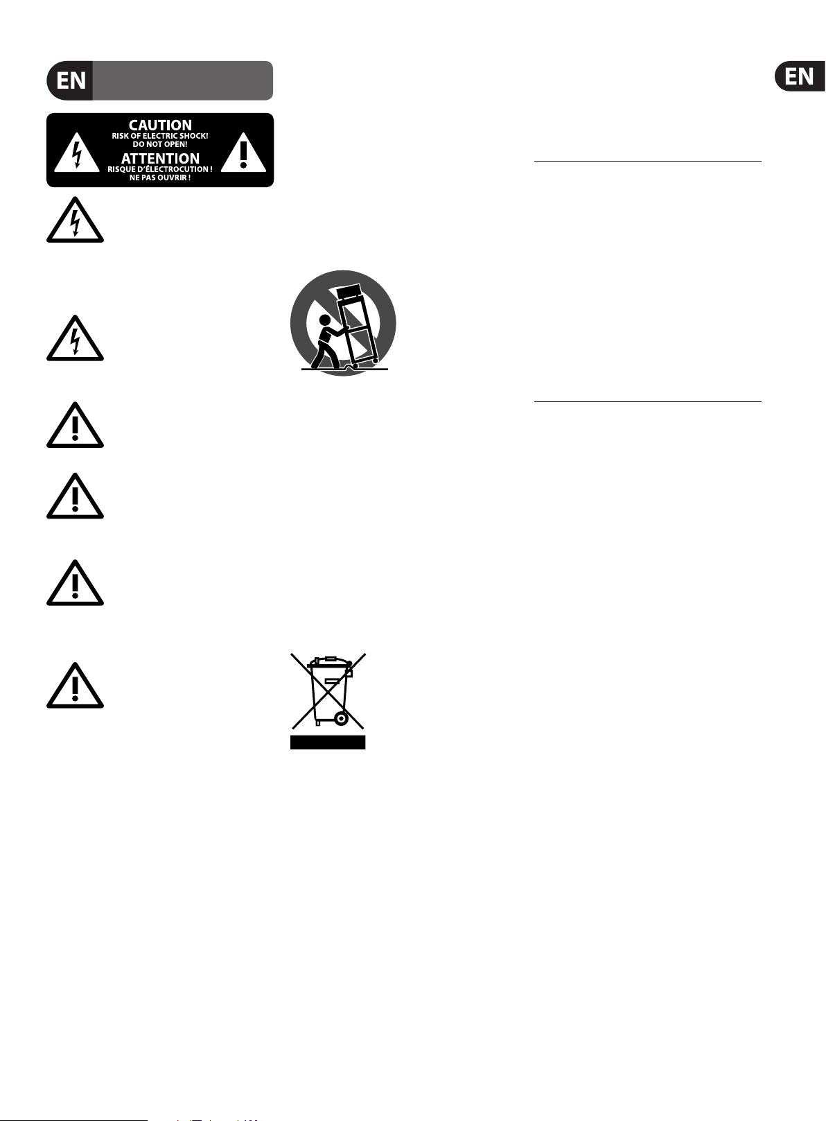
Terminals marked with this symbol carry
electrical current of su cient magnitude
to constitute risk of electric shock.
Use only high-quality professional speaker cables with
¼" TS or twist-locking plugs pre-installed. Allother
installation or modi cation should be performed only
by quali edpersonnel.
This symbol, wherever it appears,
alertsyou to the presence of uninsulated
dangerous voltage inside the
enclosure-voltage that may be su cient to constitute a
risk ofshock.
This symbol, wherever it appears,
alertsyou to important operating and
maintenance instructions in the
accompanying literature. Please read the manual.
Caution
To reduce the risk of electric shock, donot
remove the top cover (or the rear section).
No user serviceable parts inside. Refer servicing to
quali ed personnel.
Caution
To reduce the risk of re or electric shock,
do not expose this appliance to rain and
moisture. The apparatus shall not be exposed to dripping
or splashing liquids and no objects lled with liquids,
suchas vases, shall be placed on the apparatus.
Caution
These service instructions are for use
by quali ed ser vice personnel only.
Toreduce the risk of electric shock do not perform any
servicing other than that contained in the operation
instructions. Repairs have to be performed by quali ed
servicepersonnel.
1. Read these instructions.
2. Keep these instructions.
3. Heed all warnings.
4. Follow all instructions.
5. Do not use this apparatus near water.
6. Clean only with dry cloth.
7. Do not block any ventilation openings. Install in
accordance with the manufacturer’s instructions.
8. Do not install near any heat sources such as
radiators, heat registers, stoves, or other apparatus
(including ampli ers) that produce heat.
or grounding-type plug. A polarized plug has two blades
with one wider than the other. A grounding-type plug
has two blades and a third grounding prong. The wide
blade or the third prong are provided for your safety. Ifthe
provided plug does not t into your outlet, consult an
electrician for replacement of the obsolete outlet.
10. Protect the power cord from being walked on or
pinched particularly at plugs, convenience receptacles,
and the point where they exit from the apparatus.
11. Use only attachments/accessories speci ed by
themanufacturer.
12. Use only with the
cart, stand, tripod, bracket,
or table speci ed by the
manufacturer, orsold with
the apparatus. When a cart
is used, use caution when
moving the cart/apparatus
combination to avoid
injury from tip-over.
13. Unplug this apparatus during lightning storms or
when unused for long periods of time.
14. Refer all servicing to quali ed service personnel.
Servicing is required when the apparatus has been
damaged in any way, such as power supply cord or plug
is damaged, liquid has been spilled or objects have fallen
into the apparatus, the apparatus has been exposed
to rain or moisture, does not operate normally, or has
beendropped.
15. The apparatus shall be connected to a MAINS socket
outlet with a protective earthing connection.
16. Where the MAINS plug or an appliance coupler is
used as the disconnect device, the disconnect device shall
remain readily operable.
17. Correct disposal of this
product: This symbol indicates that
this product must not be disposed
of with household waste,
according to the WEEE Directive
(2012/19/EU) and your national
law. This product should be taken
to a collection center licensed for the recycling of waste
electrical and electronic equipment (EEE). The
mishandling of this type of waste could have a possible
negative impact on the environment and human health
due to potentially hazardous substances that are generally
associated with EEE. At the same time, your cooperation
in the correct disposal of this product will contribute to
the e cient use of natural resources. For more
information about where you can take your waste
equipment for recycling, please contact your local city
o ce, or your household waste collection service.
18. Do not install in a con ned space, such as a book
case or similar unit.
19. Do not place naked ame sources, such as lighted
candles, on the apparatus.
disposal in mind. Batteries must be disposed-of at a
battery collection point.
21. Use this apparatus in tropical and/or
moderate climates.
LEGAL DISCLAIMER
MUSIC Group accepts no liability for any loss which
may be su ered by any person who relies either
wholly or in part upon any description, photograph,
appearances and other information are subject to
change without notice. All trademarks are the property
of their respective owners. MIDAS, KLARK TEKNIK,
LAB GRUPPEN, LAKE, TANNOY, TURBOSOUND,
TC ELECTRONIC, TC HELICON, BEHRINGER, BUGERA
and DDA are trademarks or registered trademarks
of MUSIC Group IP Ltd. © MUSIC Group IP Ltd.
2016 All rights reserved.
LIMITED WARRANTY
For the applicable warranty terms and conditions
and additional information regarding MUSIC Group’s
Limited Warranty, please see complete details online at
music-group.com/warranty.
Page 4

4 SUPER-X PRO CX2310 User Manual
1. Introduction
If you want to operate a loudspeaker system, which consists of several
loudspeakers covering dierent frequency bands, then you naturally have
to work with suitably dierentiated input signals for each loudspeaker.
To do this you need a frequency crossover which can split the input signal
into several frequency bands. A dierence should be noted between passive
crossovers which are wired between amplier and speaker, and active systems
which are placed before the ampliers in the signal chain. Multi-way speaker
systems can be found almost everywhere today—and not only in stereo
systems, but in cinemas, discotheques and concert halls. As customers have
become more demanding they can even be found now in such “simple”
products as TV sets. Why?
With the same sound pressure, low-frequency sound waves have a much
greater amplitude (oscillation range) than high-frequency waves. When a single
loudspeaker tries to produce bass and treble frequencies at the same time,
a so-called intermodulation distortion will occur. This means that, when the
speaker diaphragm is displaced by low frequencies, the treble frequencies seem
to be raised in loudness, or lowered when the diaphragm reverses its direction.
We cannot therefore expect a single loudspeaker to reproduce signals,
spanning the whole audible frequency spectrum at the same level of quality.
If, using a frequency crossover, a loudspeaker only has to reproduce a limited
part of the frequency spectrum and it will do so at a greatly increased level
of quality— thus producing a more regular frequency response
and dispersion pattern.
Connection to the mains is made by means of a mains cable with
an IEC receptacle which complies with the appropriate safety regulations.
◊ Please note that all units must be grounded properly. For your own
safety, you should never remove any ground connectors from electrical
devices or power cords or render them inoperative.
1.2 Online registration
Please register your new BEHRINGER equipment right after your purchase
by visiting http://behringer.com and read the terms and conditions of our
warranty carefully.
Should your BEHRINGER product malfunction, it is our intention to have it
repaired as quickly as possible. To arrange for warranty ser vice, please contact
the BEHRINGER retailer from whom the equipment was purchased. Should
your BEHRINGER dealer not be located in your vicinity, you may directly contact
one of our subsidiaries. Corresponding contact information is included in the
original equipment packaging (Global Contact Information/European Contact
Information). Should your country not be listed, please contact the distributor
nearest you. A list of distributors can be found in the support area of our website
(http://behringer.com).
Registering your purchase and equipment with us helps us process your repair
claims more quickly and eciently.
Thank you for your cooperation!
◊ This manual first describes the terminology used, so that you can fully
understand the SUPER-X PRO and its functions. Please read the manual
carefully and keep it for future reference.
1.1 Before you begin
The BEHRINGER SUPER-X PRO CX2310 was carefully packed in the factory,
in order to ensure safe transport. Nevertheless, should the box show signs
of damage please check the equipment itself immediately for any signs
of external damage.
◊ If the unit is damaged, please do not return it to us, but notify your
dealer and the shipping company immediately, otherwise claims for
damage or replacement may not be granted. Shipping claims must
be made by the consignee.
Be sure that there is enough space around the unit for cooling and please do not
place the SUPER-X PRO on high-temperature devices such as power ampliers,
etc. to avoid overheating.
◊ Before connecting the SUPER-X PRO to the mains, please carefully
check that your equipment is set to the correct supply voltage!
The fuse holder on the female mains connector has 3 triangular markings.
Two of these triangles are opposite each other. The CX2310 is set to the operating
voltage shown next to these markings. It can be set to another voltage by turning
the fuse holder through 180°.
CAUTION: this does not apply to export models, which were designed
e.g. only for a mains voltage of 115 V!
2. Control Elements
Since the SUPER-X PRO oers a variety of features, we have provided the active
controls with suitable light-emitting diodes. These displays help you to keep
track of what is happening even in dark stage environments. Additionally, all the
switches on the front panel are illuminated and can thus show which functions
are presently active. There are two labels in the form of strips, located above
the controls. The text of the upper label indicates mono 3-way, and the lower
label indicates stereo 2-way mode. The LED’s set below these labels show which
controls are active in the respective mode of operation.
◊ On the rear panel, labels above/below the connectors refer to the
various crossover modes available. Please make sure that the
MODE switch and corresponding connectors are configured
properly; otherwise, you could damage your speakers.
2.1 Stereo 2-way operation with separate subwoofer signal
First, activate the 2-way mode using the MODE switch on the rear panel
(switch depressed). The STEREO LED on the front panel above the LOW CUT
switch in the second channel lights up.
The LED’s above the active control on the front panel then light up. They show
you which controls are active for the mode of operation, which you have selected.
The functions of these controls can be seen from the second strip label. In stereo
operation the func tions of both channels are identical, so that the numbers
on the overview are shown for only one channel.
Page 5
5 SUPER-X PRO CX2310 User Manual
(INPUT)
(CLIP) (LOW CUT)
(INPUT) (INPUT)
(LOW/MID)
(LOW CUT) (LOW CUT)
(LOW OUTPUT)
(LOW/HIGH) (LOW/HIGH)
(LOW OUTPUT)
(HIGH OUTPUT)
(CLIP)(CLIP)
(MID/HIGH)
(1) (2) (3) (4) (6)(5)(7) (9)(8) (11)(10) (13) (12)
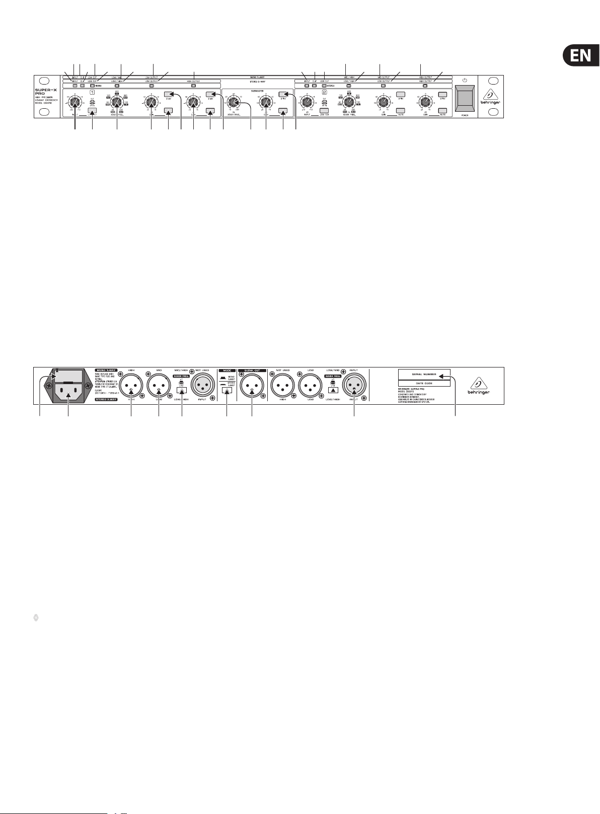
Fig. 2.1: Active contr ol elements on the f ront panel of the SUPER -X PRO in stereo 2-way oper ation with separ ate subwoofer signa l
(HIGH OUTPUT)(MID OUTPUT)
(HIGH OUTPUT)(LOW OUTPUT)
(1) INPUT control. This control adjusts the input gain over the range
from -12 to +12 dB.
(2) LOW CUT switch. This switch activates the 25 Hz high-pass lter.
It has a side gradient of 12 dB/octave and is used to protect your
bass loudspeaker.
(3) LOW/HIGH XOVER FREQ. control. This control governs the crossover
frequency between the low and high bands.
(4) LOW OUTPUT control. Controls the output level of the low band over the
range from -6 to +6 dB.
(5) LOW PHASE INVERT switch. This switch reverses the polarity of the
low output.
(6) LOW MUTE switch. This is used to mute the low band.
(2) (3) (5) (6)
Fig. 2.2: Ac tive control elem ents and connec tions on the rear pan el of the SUPER-X PRO in stere o 2-way operation wit h separate subwoo fer signal
(1) HIGH OUTPUT connectors. These are the balanced XLR connectors for the
high band output signal.
(2) LOW OUTPUT connectors. These are the balanced XLR connectors for the
low band output signal.
(3) XOVER FREQ. switch. These switches are used to switch between the
control ranges on the front panel LOW/HIGH XOVER FREQ. control.
The range is either 44 to 930 Hz or 440 Hz to 9.3 kHz.
(4) INPUT connectors. These are the balanced XLR connectors for the
input signal.
(5) MODE switch. In stereo 2-way operation the switch must be depressed.
Please refer to the text on the rear panel of the equipment.
◊ Never activate the MODE and XOVER FREQ. switches without having
first switched off the equipment. Switching between these while the
equipment is in use produces heavy interference noise which could
damage the loudspeakers or the system.
(7) HIGH OUTPUT control. This controls the output level of the high band over
the range from -6 to +6 dB.
(8) HIGH PHASE INVERT switch. This switch reverses the polarity of the
high output.
(9) HIGH MUTE switch. This is used to mute the high band.
(10) XOVER FREQ. control. This control governs the crossover frequency between
the low signal and the subwoofer signal (10 to 215 Hz).
(11) GAIN control. This is used to set the subwoofer output volume at the
SUBW. OUT output.
(12) PHASE INVERT switch. This switch reverses the polarity of the subwoofer
output signal.
(13) MUTE switch. This mutes the subwoofer output signal.
(4)
(6) SUBW. OUT con nector. This is the balanced XLR output for the mono
subwoofer signal. This signal is constant in mono and stereo mode and
provides an additional means of providing 2- and 3-way operation
(see chapter 3.5).
(7) IEC-RECEPTACLE. This is the mains connection of the SUPER-X PRO.
A suitable mains cable is included with the equipment.
(8) FUSE HOLDER /VOLTAGE SELECTOR. Before connecting the equipment
to the mains supply, please check that the voltage display conforms with
your mains voltage supply. When replacing the fuse, make sure you use
another one of the same type. With many units the fuse holder can be set
in one of two positions, in order to switch between 230 V and 115 V.
Please note: if you wish to operate a unit outside Europe,
then a stronger fuse must be used.
(9) SERIAL NUMBER. Please take the time to complete and return the warranty
card within 14 days of the date of purchase, other wise you will lose the right
to the extended warranty. Or just use our online-registration
(behringer.com).
(9)(8) (7) (1)
Page 6
6 SUPER-X PRO CX2310 User Manual
(INPUT)
(CLIP) (LOW CUT)
(INPUT) (INPUT)
(LOW/MID)
(LOW CUT) (LOW CUT)
(LOW OUTPUT)
(LOW/HIGH) (LOW/HIGH)
(LOW OUTPUT)
(HIGH OUTPUT)
(MID/HIGH)
(CLIP)(CLIP)
(HIGH OUTPUT)(MID OUTPUT)
(HIGH OUTPUT)(LOW OUTPUT)
(1) (2) (3) (4) (6) (5) (9) (8) (15) (17) (16) (9)(8)
(7) (14) (11)
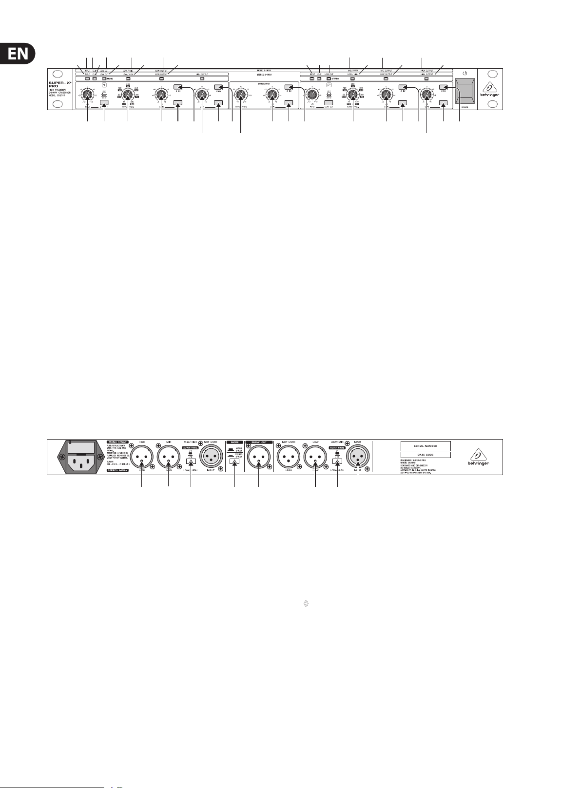
Fig. 2.3: Acti ve control element s on the front pan el of the SUPER-X PRO in mono 3-w ay operation with s eparate subwoofe r signal
2.2 Mono 3-way operation with separate subwoofer signal
First activate mono 3-way mode using the MODE switch on the rear panel
(switch released). The MONO LED on the front panel above the LOW CUT
switch lights up.
Then the LED’s above the active control on the front panel light up. They show
which controls are active for the mode of operation, which you have selected.
The text on the rst label shows the functions of these controls.
(1) INPUT control. This control adjusts the input gain from -12 to +12 dB.
(2) LOW CUT switch. This switch activates the 25 Hz high pass lter.
(3) LOW/MID XOVER FREQ. control. This control governs the crossover
frequency between the low and middle bands.
(4) LOW OUTPUT control. This controls the output level of the low band over
the range -6 to +6 dB.
(5) LOW PHASE INVERT switch. This switch is used to reverse the polarity
of the low output.
(6) LOW MUTE switch. This is used to mute the low band.
(7) MID/HIGH XOVER FREQ. control. This control governs the crossover
frequency between the mid and high bands.
(8) MID OUTPUT control. This is used to control the output level of the mid band
over the range -6 to +6 dB.
(9) MID PHASE INVERT switch. This reverses the polarity of the mid output.
(10) MID MUTE switch. This is used to mute the mid band.
(11) HIGH OUTPUT control. This controls the output level of the high band over
the range from -6 to +6 dB.
(12) HIGH PHASE INVERT switch. This reverses the polarity of the high output.
(13) HIGH MUTE switch. This is used to mute the high band.
(14) XOVER FREQ. control. This control governs the crossover frequency between
the low signal and the subwoofer signal.
(15) GAIN control. This sets the subwoofer output volume level at the
SUBW.OUT output.
(16) PHASE INVERT switch. This switch is used to reverse the polarity of the
subwoofer output signal.
(17) MUTE switch. This is used to mute the subwoofer output signal.
(10) (13) (12)(7)
(1) (2) (7) (6)(5)(3)(8)(4)
Fig. 2.4: Activ e control element s and connectio ns on the rear panel of t he SUPER-X PRO in mono 3-way ope ration with sepa rate subwoofer sig nal
(1) HIGH OUTPUT connec tor. This is the balanced XLR connector for the high
output signal.
(2) MID OUTPUT connec tor. This is the balanced XLR connector for the mid
output signal.
(3) LOW OUTPUT connector. This is the balanced XLR connector for the low
output signal.
(4) XOVER FREQ. switch. This is used to switch between the control ranges
of the front panel MID/HIGH XOVER FREQ. control. The range is either
44 to 930 Hz or 440 Hz to 9.3 kHz.
(5) XOVER FREQ. switch. This is used to switch between the control ranges
of the front panel LOW/MID XOVER FREQ. control. The range is either
44 to 930 Hz or 440 Hz to 9.3 kHz.
(6) INPUT conn ector. This is the balanced XLR connector for the input signal.
(7) MODE switch. This must be de-activated when in mono 3-way operation.
◊ Never activate the MODE and XOVER FREQ. switches without having
first switched off the equipment. Switching between these whilst the
equipment is in use produces heavy interference noise which could
damage the loudspeakers or the system.
(8) SUBW. OUT con nector. This is the output for the mono subwoofer signal.
This signal remains constant in mono and stereo mode and oers an
additional way of providing 2-way and 3-way operation (see chapter 3.5).
Page 7

7 SUPER-X PRO CX2310 User Manual
3. Applications
You will need some tools to help set up the SUPER-X PRO to its optimal
conguration. To set up the crossover frequency you need to know which
frequency range a loudspeaker stack covers, over which range the sound
energy is linearly transmitted, and where reductions or increases in the
frequency response occur. In addition, every room has dierent size and quality
characteristics. These strongly inuence the sound response, since resonances
and reections in the dierent frequency ranges can also lead to reductions
or increases in the sound picture. You will need suitable equipment in order
to be able to recognize and compensate for these features.
3.1 Too ls
You will need a high-grade microphone for making measurements.
This should have a frequency response that should be as linear as possible
(e.g. the BEHRINGER measurement microphone ECM8000) and at least linear
over the range from 90 Hz and 15 kHz. Place the microphone about 5 m. in front
of the speaker system and between the diaphragms of the two frequency bands
you wish to measure. When using a measuring microphone to set the levels for
the individual frequency bands and the crossover frequencies, you should only
operate one loudspeaker stack. For optimal settings you will usually need
to reposition the microphone between two successive measurements.
When used in combination with a measuring microphone and a generator
producing pink noise via an input into the P.A. mixing console, an analyzer
will show the sound energy distribution over the individual frequency bands
(usually in 1/3 of an octave). The BEHRINGER ULTRA-CURVE PRO DSP8024
equalizer/analyzer is the ideal tool for this application.
3.3 Correcting problems
Check the entire frequency response of the system. Rooms have quite
an impact on the frequency response of speaker systems, due to resonance and
various reections, so you cannot expect to achieve a linear frequenc y response
right from the start. To achieve this, you need an equalizer such as the
ULTRA-CURVE PRO DSP8024 or the ULTRA-GRAPH GEQ3102. Look for drop-outs
around the crossover frequencies! If the frequency response is very irregular,
then it can make sense to grade adjust it using the frequenc y crossover,
before using an equalizer (EQ). The errors in the crossover frequency must then
be as far as possible corrected using the EQ.
If the loudspeaker diaphragms in a multi-way system are not exactly aligned
along a vertical axis, the varying distances between the sound source and
the listener result in phase errors and cancellations (also known as the
“comb lter eect”). Particularly in the higher frequencies it is important,
due to the shorter wavelengths, to position the diaphragms above each other
and not next to each other. The various types of construction used in individual
systems (horns, bass reex cabinets etc.) still give rise to run time dierences,
even where the front sides of all systems are aligned vertically above each other.
In this case a run time correction must be made by electronic means. This can
be done by using a delay function. Run time dierences can be compensated
by delaying the frequency bands over a range of milliseconds. This helps avoid
loss of sound quality, particularly in the high tone ranges.
◊ Runtime correction is not the same as phase correction. If a speaker
system has the same run times then it also has the same phases
(unless the polarity of a cable has been reversed). However the
opposite is not necessarily true.
When listening to the overall sound of your system, you should walk around
in the audience area and try to detect resonance frequencies or cancellations.
The sound should be optimized for the position where most of the audience
will be gathered, without however neglecting other areas. This often means
that the system must be operated in mono. Whenever you use technical aids
such as analyzers, measuring microphones, etc., you should check the desired
results with your own ears.
◊ BEHRINGER accepts no responsibility for any damage or destruction
of loudspeakers arising from improper or incorrect use of the
SUPER-X PRO and in particular from actions which are in contravention
with the clearly stated procedures given in this manual.
3.2 Setting the input and output levels
Both inputs oer a gain or loss of up to 12 dB. Normally, the output level on the
mixing console and the input sensitivity of the ampliers are identical, i.e. 0 dB
at the mixing console corresponds with 0 dB at the ampliers. This means that
there is full control over the ampliers. In this case the SUPER-X PRO should
have no eect on the system level and all input and output level settings should
be set at 0 dB. Where e.g. a home recording or disco console is being used with
an operating level of -10 dBV but the ampliers need +4 dBu for complete
control, then an additional gain of 12 dB must be provided between them.
In this case the INPUT control of the SUPER-X PRO should be set to the maximum.
The output levels of the single bands can be raised/lowered by as much as 6 dB.
To achieve a linear frequency response in the system, all output levels should
be adjusted with the help of an analyzer. To check the crossover frequencies and
levels, mute all outputs except for one, and play back pink noise over the system
at an appropriate volume level. When you now switch on the adjacent band,
the level measured around the crossover frequency should go up by 3 dB.
Repeat this process for all crossover frequencies.
3.4 Setting the crossover frequencies
The frequency range from which the crossover frequencies can be selected,
can be one of two ranges—from 44 to 930 Hz and from 440 Hz to 9.3 kHz.
To set the crossover frequencies, please rst read the manufacturers’
specications for the individual loudspeaker components. To use the capacity
of your system at its best you should set up the crossover frequencies in
accordance with the frequency diagrams on the individual loudspeaker boxes.
Further, the crossovers should not lie on peaks or drop-outs. Look for a range
with the attest possible curve. If folded bass horns are being used, then the
length of the horn path must also be taken into account, since the run time
displacements arising from diering long paths can also have a negative eect
on the frequency development (see chapter 3.3).
◊ Never operate loudspeakers or horn drivers below the limiting
frequency specified by the manufacturer!
3.5 SUBWOOFER output
To achieve a very loud and deep bass playback the SUPER-X PRO has an additional
mono subwoofer output for 2-way and 3-way operation. In this sense the
CX2310 is a stereo 2-way + mono 1-way or mono 4-way frequency crossover.
The subwoofer signal is mono, since people cannot sense the location of lower
frequencies. Another reason is that combining all bass signals into a single signal
produces an excellent eect. This is because two bass speaker boxes combined
together produce 3 dB more sound pressure than if they were separated from
each other by a small distance. The increased pressure is due to the speakers
producing a single wave front. With four loudspeaker boxes the increase is 6 dB.
The reason here is the spherical shape of the expanding low-frequency sound
waves. Bass boxes which are separate from each other can mutually disrupt each
other where their sound waves meet (what happens here can be easily imagined
if you throw two stones into water—rst separately and then stuck together).
Page 8
8 SUPER-X PRO CX2310 User Manual
4. Audio Connections
As a standard, the BEHRINGER SUPER-X PRO CX2310 is equipped with
electronically servo-balanced inputs and outputs. The circuit design features
automatic hum suppression for balanced signals and so ensures trouble-free
operation, even at the highest operating levels. Externally induced mains hum,
etc. can therefore be eectively suppressed. The automatic servo-function
recognizes the presence of unbalanced connectors and adjusts the nominal level
internally to avoid level dierences between the input and output signals
(6-dB correction).
◊ Please ensure that only qualified persons install and operate the
SUPER-X PRO. During installation and operation the user must have
sufficient electrical contact to earth. Electrostatic charges might affect
the operation of the unit.
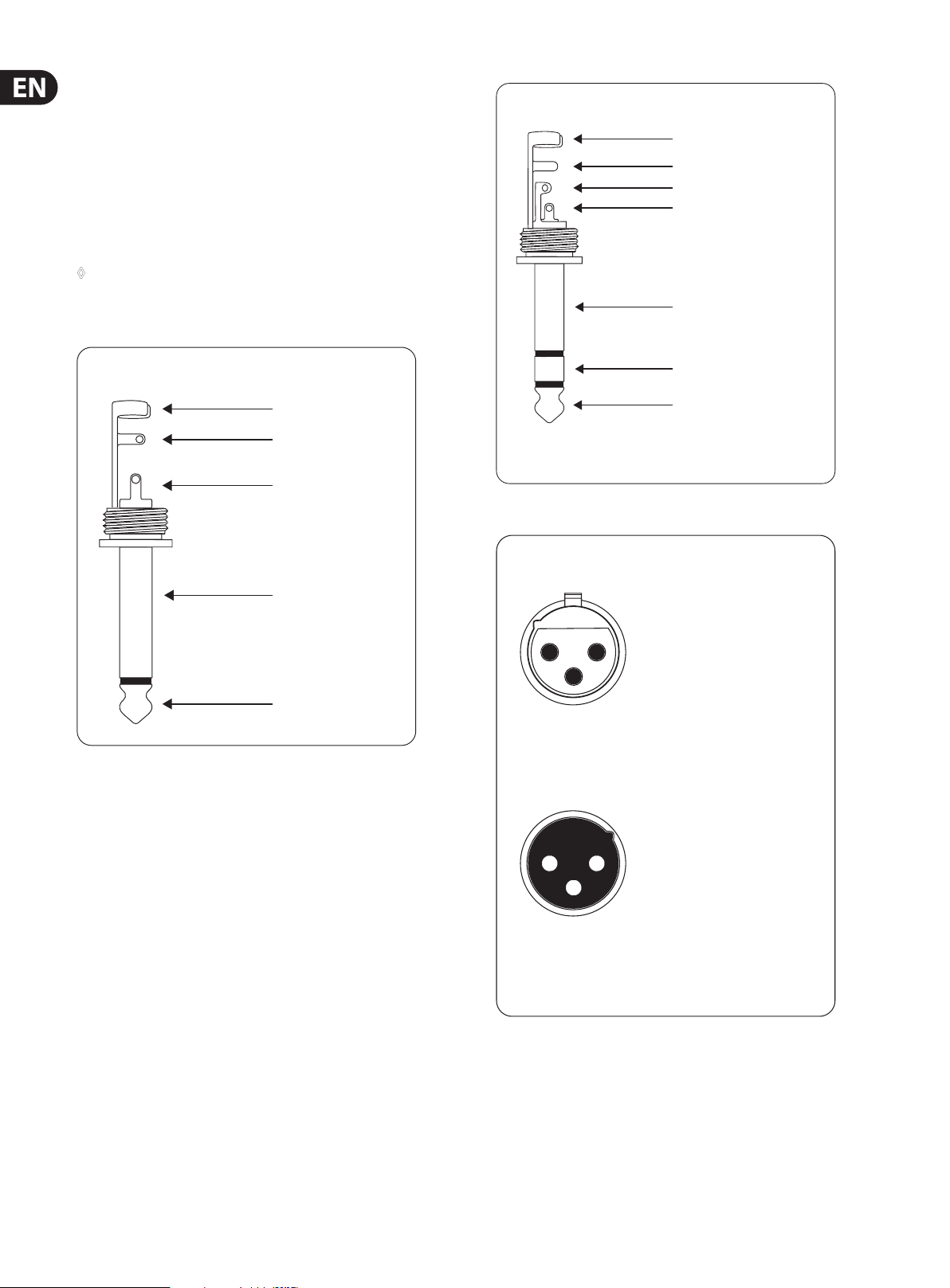
Unbalanced ¼" TS connector
strain relief clamp
sleeve
tip
Balanced ¼" TRS connector
strain relief clamp
sleeve
ring
tip
sleeve
ground/shield
ring
cold (-ve)
tip
hot (+ve)
For connection of balanced and unbalanced plugs,
ring and sleeve have to be bridged at the stereo plug.
sleeve
(ground/shield)
tip
(signal)
Balanced use with XLR connectors
12
3
input
1 = ground/shield
2 = hot (+ve)
3 = cold (-ve)
1
2
3
output
For unbalanced use, pin 1 and pin 3
have to be bridged
Fig. 4.1: Dierent plug t ypes
Page 9
9 SUPER-X PRO CX2310 User Manual
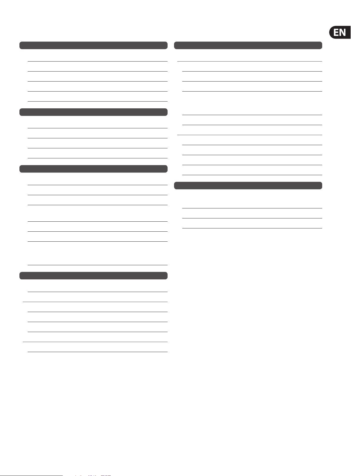
5. Specications
Inputs
Connectors XLR
Type Electronically servo-balanced, HF ltered
Impedance balanced >50 kOhm, unbalanced >25 kOhm
Max. Input level +22 dBu typical, balanced or unbalanced
CMRR >40 dB, typical >55 dB at 1 kHz
Outputs
Connectors XLR
Type Electronically servo-balanced, HF ltered
Impedance balanced 60 Ohm, unbalanced 30 Ohm
Max. Output level +20 dBm balanced/unbalanced
Performance
Bandwidth 20 Hz to 20 kHz, +0/-0.5 dB
Frequency response <5 Hz to >60 kHz, +0/-3 dB
Signal to noise Ref.: +4 dBu, 20 Hz to 20 kHz, unweighted
Stereo-Mode: Mono-Mode:
Low output >93 dB >93 dB
Mid output >95 dB
Power Supply
Mains voltage
USA/Canada 120 V~, 60 Hz
U.K./Australia 240 V~, 50 Hz
Europe 230 V~, 50 Hz
General Export Model 100 - 120 V~,
200 - 240 V~,
50 - 60 Hz
Power consumption <17 W
Fuse
UL 100 - 120 V~: T 630 mA H
Europe 200 - 240 V~: T 315 mA H
JP 90 - 110 V~: T 630 mA H
Mains connection Standard IEC receptacle
Physical/Weight
Dimensions approx. 44.5 x 482.6 x 215 mm
(1.75 x 19 x 8.5")
Net Weight 2.3 kg (5 lbs)
Shipping Weight 3.4 kg (7.5 lbs)
High output >91 dB >91 dB
Interchannel crosstalk High to Low: <93 dB
High to Mid: <94 dB
Mid to Low: <95 dB
Crossover
Filter-Type Linkwitz-Riley, 24 dB/octave, state-variable
Mono Mode Frequencies x1 x10
Low/High 44 to 930 Hz 440 Hz to 9.3 kHz
Low/Mid 44 to 930 Hz 440 Hz to 9.3 kHz
Mid/High 440 Hz to 9.3 kHz
Stereo Mode Frequencies x1 x10
Low/High 44 to 930 Hz 440 Hz to 9.3 kHz
BEHRINGER i s constantly str iving to maintain the h ighest profess ional standards. A s a result of these e ffort s,
modific ations may be made f rom time to time to exi sting product s without prio r notice. Specif ications and
appearance m ay differ fro m those listed or illus trated.
Page 10

Dedicate Your Life to Music
 Loading...