

Page 1
Quick Start Guide
CM1A
MIDI to CV Converter Module for Eurorack
V 1.0
Page 2

2 3Quick Start GuideCM1A
LEGAL DISCLAIMER
Music Tribe accepts no liability for any loss
which may be suered by any person who
relies either wholly or in part upon any
description, photograph, or statement
contained herein. Technical specications,
appearances and other information are
subject to change without notice. All
trademarks are the property of their
respective owners. Midas, Klark Teknik,
Lab Gruppen, Lake, Tannoy, Turbosound,
TC Electronic, TC Helicon, Behringer, Bugera,
Oberheim, Auratone, Aston Microphones,
Aston Microphones and Coolaudio are
trademarks or registered trademarks of
Music Tribe Global Brands Ltd. © Music Tribe
Global Brands Ltd. 2021 All rights reserved.
LIMITED WARRANTY
For the applicable warranty terms and
conditions and additional information
regarding Music Tribe’s Limited Warranty,
please see complete details online at
musictribe.com/warranty.
NEGACIÓN LEGAL
Music Tribe no admite ningún tipo de
responsabilidad por cualquier daño o
pérdida que pudiera sufrir cualquier persona
por conar total o parcialmente en la
descripciones, fotografías o armaciones
contenidas en este documento. Las
especicaciones técnicas, imágenes y
otras informaciones contenidas en este
documento están sujetas a modicaciones
sin previo aviso. Todas las marcas comerciales
que aparecen aquí son propiedad de sus
respectivos dueños. Midas, Klark Teknik,
Lab Gruppen, Lake, Tannoy, Turbosound,
TC Electronic, TC Helicon, Behringer, Bugera,
Oberheim, Auratone, Aston Microphones
y Coolaudio son marcas comerciales o
marcas registradas de Music Tribe Global
Brands Ltd. © Music Tribe Global Brands Ltd.
2021 Reservados todos los derechos.
GARANTÍA LIMITADA
Si quiere conocer los detalles y condiciones
aplicables de la garantía así como
información adicional sobre la Garantía
limitada de Music Tribe, consulte online
toda la información en la web
musictribe.com/warranty.
DÉNI LÉGAL
Music Tribe ne peut être tenu pour
responsable pour toute perte pouvant
être subie par toute personne se ant en
partie ou en totalité à toute description,
photographie ou armation contenue
dans ce document. Les caractéristiques,
l’apparence et d’autres informations
peuvent faire l’objet de modications
sans notication. Toutes les marques
appartiennent à leurs propriétaires
respectifs. Midas, Klark Teknik, Lab Gruppen,
Lake, Tannoy, Turbosound, TC Electronic,
TC Helicon, Behringer, Bugera, Oberheim,
Auratone, Aston Microphones et Coolaudio
sont des marques ou marques déposées de
Music Tribe Global Brands Ltd. © Music Tribe
Global Brands Ltd. 2021 Tous droits réservés.
GARANTIE LIMITÉE
Pour connaître les termes et conditions
de garantie applicables, ainsi que les
informations supplémentaires et
détaillées sur la Garantie Limitée de
Music Tribe, consultez le site Internet
musictribe.com/warranty.
HAFTUNGSAUSSCHLUSS
Music Tribe übernimmt keine Haftung für
Verluste, die Personen entstanden sind, die
sich ganz oder teilweise auf hier enthaltene
Beschreibungen, Fotos oder Aussagen
verlassen haben. Technische Daten,
Erscheinungsbild und andere Informationen
können ohne vorherige Ankündigung
geändert werden. Alle Warenzeichen sind
Eigentum der jeweiligen Inhaber. Midas,
Klark Teknik, Lab Gruppen, Lake, Tannoy,
Turbosound, TC Electronic, TC Helicon,
Behringer, Bugera, Oberheim, Auratone,
Aston Microphones und Coolaudio
sind Warenzeichen oder eingetragene
Warenzeichen der Music Tribe Global Brands
Ltd. © Music Tribe Global Brands Ltd. 2021
Alle Rechte vorbehalten.
BESCHRÄNKTE GARANTIE
Die geltenden Garantiebedingungen und
zusätzliche Informationen bezüglich der
von Music Tribe gewährten beschränkten
Garantie nden Sie online unter
musictribe.com/warranty.
LEGAL RENUNCIANTE
O Music Tribe não se responsabiliza por
perda alguma que possa ser sofrida por
qualquer pessoa que dependa, seja de
maneira completa ou parcial, de qualquer
descrição, fotograa, ou declaração aqui
contidas. Dados técnicos, aparências
e outras informações estão sujeitas a
modicações sem aviso prévio. Todas
as marcas são propriedade de seus
respectivos donos. Midas, Klark Teknik,
Lab Gruppen, Lake, Tannoy, Turbosound,
TC Electronic, TC Helicon, Behringer, Bugera,
Oberheim, Auratone, Aston Microphones
e Coolaudio são marcas ou marcas
registradas do Music Tribe Global Brands
Ltd. © Music Tribe Global Brands Ltd.
2021 Todos direitos reservados.
GARANTIA LIMITADA
Para obter os termos de garantia aplicáveis
e condições e informações adicionais a
respeito da garantia limitada do Music Tribe,
favor vericar detalhes na íntegra através do
website musictribe.com/warranty.
DISCLAIMER LEGALE
Music Tribe non si assume alcuna
responsabilità per eventuali danni che
possono essere subiti da chiunque si adi
in tutto o in parte a qualsiasi descrizione,
fotograa o dichiarazione contenuta
qui. Speciche tecniche, aspetti e altre
informazioni sono soggette a modiche
senza preavviso. Tutti i marchi sono di
proprietà dei rispettivi titolari. Midas,
Klark Teknik, Lab Gruppen, Lake, Tannoy,
Turbosound, TC Electronic, TC Helicon,
Behringer, Bugera, Oberheim, Auratone,
Aston Microphones e Coolaudio sono marchi
o marchi registrati di Music Tribe Global
Brands Ltd. © Music Tribe Global Brands
Ltd. 2021 Tutti i diritti riservati.
GARANZIA LIMITATA
Per i termini e le condizioni di garanzia
applicabili e le informazioni aggiuntive
relative alla garanzia limitata di Music Tribe,
consultare online i dettagli completi su
musictribe.com/warranty.
WETTELIJKE ONTKENNING
Music Tribe aanvaardt geen
aansprakelijkheid voor enig verlies dat
kan worden geleden door een persoon die
geheel of gedeeltelijk vertrouwt op enige
beschrijving, foto of verklaring hierin.
Technische specicaties, verschijningen
en andere informatie kunnen zonder
voorafgaande kennisgeving worden
gewijzigd. Alle handelsmerken zijn
eigendom van hun respectievelijke
eigenaren. Midas, Klark Teknik, Lab
Gruppen, Lake, Tannoy, Turbosound,
TC Electronic, TC Helicon, Behringer, Bugera,
Oberheim, Auratone, Aston Microphones
en Coolaudio zijn handelsmerken of
gedeponeerde handelsmerken van Music
Tribe Global Brands Ltd. © Music Tribe
Global Brands Ltd. 2021 Alle rechten
voorbehouden.
BEPERKTE GARANTIE
Voor de toepasselijke garantievoorwaarden
en aanvullende informatie met betrekking
tot de beperkte garantie van Music Tribe,
zie de volledige details online op
musictribe.com/warranty.
FRISKRIVNINGSKLAUSUL
Music Tribe tar inget ansvar för någon
förlust som kan drabbas av någon person
som helt eller delvis förlitar sig på någon
beskrivning, fotogra eller uttalande
som nns här. Tekniska specikationer,
utseenden och annan information kan
ändras utan föregående meddelande. Alla
varumärken tillhör respektive ägare. Midas,
Klark Teknik, Lab Gruppen, Lake, Tannoy,
Turbosound, TC Electronic, TC Helicon,
Behringer, Bugera, Oberheim, Auratone,
Aston Microphones och Coolaudio är
varumärken eller registrerade varumärken
som tillhör Music Tribe Global Brands Ltd.
© Music Tribe Global Brands Ltd. 2021 Alla
Rättigheter reserverade.
BEGRÄNSAD GARANTI
För tillämpliga garantivillkor och ytterligare
information om Music Tribes begränsade
garanti, se fullständig information online på
musictribe.com/warranty.
ZASTRZEŻENIA PRAWNE
Music Tribe nie ponosi odpowiedzialności
za jakiekolwiek straty, które mogą ponieść
osoby, które polegają w całości lub w
części na jakimkolwiek opisie, fotograi
lub oświadczeniu zawartym w niniejszym
dokumencie. Specykacje techniczne,
wygląd i inne informacje mogą ulec zmianie
bez powiadomienia. Wszystkie znaki
towarowe są własnością ich odpowiednich
właścicieli. Midas, Klark Teknik,
Lab Gruppen, Lake, Tannoy, Turbosound,
TC Electronic, TC Helicon, Behringer, Bugera,
Oberheim, Auratone, Aston Microphones
i Coolaudio są znakami towarowymi lub
zastrzeżonymi znakami towarowymi rmy
Music Tribe Global Brands Ltd. © Music Tribe
Global Brands Ltd. 2021 Wszystkie prawa
zastrzeżone.
OGRANICZONA
GWARANCJA
Aby zapoznać się z obowiązującymi
warunkami gwarancji i dodatkowymi
informacjami dotyczącymi ograniczonej
gwarancji Music Tribe, zapoznaj się ze
wszystkimi szczegółami w trybie online pod
adresem musictribe.com/warranty.
Page 3
(1)
(2)
(3)
(5)(4)
(6)
4 5Quick Start GuideCM1A
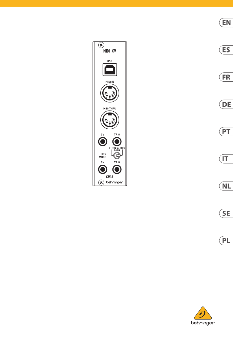
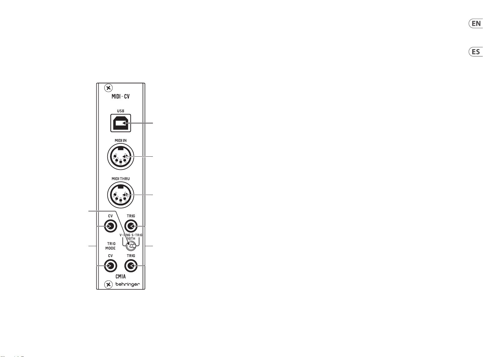
CM1A
(EN) Controls
(ES) Controles
(1) USB - Connect to a
computer to transmit
MIDI control signals to the
CV and Trig outputs. The
module can also receive
rmware updates via this
connection.
(2) MIDI IN - Connect a MIDI
controller to transmit
signals to the CV and Trig
outputs.
(3) MIDI THRU - Pass the
signals received at the MIDI
In jack to other devices.
(1) USB - Conéctelo a un
ordenador para transmitir
señales de control MIDI
a las salidas CV y de
disparador (Trig). El módulo
también puede recibir
actualizaciones de rmware
a través de esta conexión.
(2) MIDI IN - Conecte un
controlador MIDI para
transmitir señales a las
salidas CV y de disparador
(Tr ig).
(3) MIDI THRU - Esta toma
le permite derivar sin
modicación alguna las
señales recibidas en la toma
MIDI In a otros dispositivos.
(4) CV - Send control voltages
received via USB or MIDI to
other modules.
(5) TRIG - Send trigger signals
received via USB or MIDI to
other modules.
(6) TRIG MODE - Selects
whether the Trig outputs
function as V-trig or S-Trig.
In the middle position, the
upper output functions as
S-trig and the lower output
functions as V-trig.
(4) CV - Envía a otros módulos
las señales de voltaje de
control recibidos vía USB
o MIDI.
(5) TRIG - Envía a otros
módulos las señales de
disparador recibidas vía USB
o MIDI.
(6) TRIG MODE - Le permite
elegir si las salidas de
disparador (Trig) actuarán
como V-trig o S-Trig. En la
posición central, la salida
superior actuará como S-trig
y la salida inferior
como V-trig. .
Page 4

6 7Quick Start GuideCM1A
(1) USB - Permet la connexion
à un ordinateur an de
transmettre des signaux de
contrôle MIDI aux sorties
CV et Trig. Vous pouvez
également utiliser ce
port pour mettre à jour le
rmware du module.
(2) MIDI IN - Permet de
connecter un contrôleur
MIDI an de transmettre
des signaux aux sorties CV
et Trig.
(3) MIDI THRU - Permet de
transmettre les signaux
reçus à l’entrée MIDI à
d’autres appareils.
(1) USB - wird an einen
Computer angeschlossen,
um MIDI-Steuersignale an
die CV- und Trig-Ausgänge
zu übertragen. Das Modul
kann über diese Verbindung
auch Firmware-Updates
empfangen.
(2) MIDI IN - Hier schließen Sie
einen MIDI-Controller an,
um Signale an die CV- und
Trig-Ausgänge zu senden.
(3) MIDI THRU - leitet die
an der MIDI In-Buchse
empfangenen Signale an
andere Geräte weiter.
(4) CV - Permet de transmettre
la tension de contrôle reçue
par USB ou MIDI à d’autres
modules.
(5) TRIG - Permet de
transmettre les signaux
de déclenchement reçus
par USB ou MIDI à d’autres
modules.
(6) TRIG MODE - Sélection du
mode de fonctionnement
des sorties Trig : V-trig
ou S-trig. Sur la position
centrale, la sortie située
au-dessus du sélecteur
fonctionne en S-trig et celle
en dessous fonctionne en
V-trig.
(4) CV - sendet über USB
oder MIDI empfangene
Steuerspannungen an
andere Module.
(5) TRIG - sendet über USB oder
MIDI empfangene TriggerSignale an andere Module.
(6) TRIG MODE - wählt aus, ob
die Trig-Ausgänge als V-Trig
oder S-Trig funktionieren.
In der Mittelstellung
funktioniert der obere
Ausgang als S-Trig und der
untere Ausgang als V-Trig.
(PT) Controles(FR) Réglages
(1) USB - Conecte a um
computador para transmitir
sinais de controle MIDI às
saídas CV e Trig. O módulo
também é capaz de receber
atualizações de rmware
por essa conexão.
(2) MIDI IN - Conecte o
controlador MIDI para
transmitir sinais às saídas
CV e Trig.
(3) MIDI THRU - Passa os sinais
recebidos no jack MIDI In a
outros dispositivos.
(IT) Controlli(DE) Bedienelemente
(1) USB - Collegare a un
computer per trasmettere
segnali di controllo MIDI
alle uscite CV e Trig. Il
modulo può anche ricevere
aggiornamenti del rmware
tramite questa connessione.
(2) MIDI IN - Collegare a
un controller MIDI per
trasmettere segnali alle
uscite CV e Trig.
(3) MIDI THRU - Passa ad altri
dispositivi i segnali ricevuto
(4) CV - Envia tensão de
controle recebida por USB
ou MIDI a outros módulos.
(5) TRIG - Envia sinais de
acionamento recebidos
por USB ou MIDI a outros
módulos.
(6) TRIG MODE - Seleciona se
o Trig faz saída de funções
como V-trig ou S-Trig. Na
posição mediana, as funções
de saídas superiores como
S-trig e as funções de saída
mais baixa como V-trig.
(4) CV - Invia ad altri moduli le
tensioni di controllo ricevute
tramite USB o MIDI.
(5) TRIG - Invia ad altri moduli
i segnali di trigger ricevuti
tramite USB o MIDI.
(6) TRIG MODE - Seleziona se
le uscite Trig funzionano
come V-trig o S-Trig. Nella
posizione centrale, l'uscita
superiore funziona come
S-trig e quella inferiore
come V-trig.
alla presa MIDI IN.
Page 5

8 9Quick Start GuideCM1A
(SE) Kontroller
(1) USB - Aansluiten op een
computer om MIDIstuursignalen naar de
CV- en Trig-uitgangen te
verzenden. De module
kan via deze aansluiting
ook rmware-updates
ontvangen.
(2) MIDI IN - Sluit een MIDI-
controller aan om signalen
naar de CV- en Triguitgangen te verzenden.
(3) MIDI THRU - Geeft de
signalen van de MIDI
In-aansluiting aan andere
apparaten door.
(1) USB - Anslut till en dator för
att skicka MIDI-styrsignaler
till CV- och Trig-utgångarna.
Modulen kan också ta emot
rmware-uppdateringar via
denna anslutning.
(2) MIDI IN - Anslut en
MIDI-kontrollenhet för att
skicka signaler till CV- och
Trig-utgångarna.
(3) MIDI THRU - Skicka vidare
de signaler som tas emot till
MIDI In-uttaget till andra
enheter.
(4) CV - Stuurspanning die
via USB of MIDI wordt
ontvangen naar andere
modules verzenden.
(5) TRIG - Via USB of MIDI
ontvangen triggersignalen
naar andere modules
verzenden.
(6) TRIG MODE - Bepaalt of de
Trig-uitgangen als V-trig
of S-Trig functioneren. In
de middenpositie werkt de
bovenste uitgang als S-trig
en de onderste uitgang als
V-trig.
(4) CV - Skicka styrspänningar
som tas emot via USB eller
MIDI till andra moduler.
(5) TRIG - Skicka
triggersignaler som tas
emot via USB eller MIDI till
andra moduler.
(6) TRIG MODE - Väljer om
Trig-utgångarna fungerar
som V-trig eller S-Trig. I
mittpositionen fungerar den
övre utgången som S-trig
och den nedre utgången
fungerar som V-trig.
(PL) Sterowanica(NL) Bediening
(1) USB - Podłącz do
komputera, aby przesyłać
sygnały kontrolne MIDI
do wyjść CV oraz Trig.
Moduł może również
odbierać aktualizacje
oprogramowania
rmowego przez to
połączenie.
(2) MIDI IN - Podłącz kontroler
MIDI, aby przesyłać sygnały
do wyjść CV oraz Trig.
(3) MIDI THRU - Przesyła
sygnały otrzymywane na
(4) CV - Przesyła napięcia
kontrolne otrzymywane
przez USB lub MIDI do
innych modułów.
(5) TRIG - Przesyła sygnały
aktywacji (trigger)
otrzymywane przez USB lub
MIDI do innych modułów.
(6) TRIG MODE - Wybiera, czy
wyjścia Trig działają jako
V-trig czy S-Trig. W pozycji
środkowej górne wyjście
działa jako S-trig,
a dolne jako V-trig.
wejściu MIDI In do innych
urządzeń.
Page 6

10 11Quick Start GuideCM1A
(EN) Mode Select
A button on the rear panel allows the CM1A to be congured for use with various synth families oered by
Behringer. The rst LED indicates whether the CV range is optimal for System 15/35/55 or System 100/2500
series modules. The second LED indicates monophonic or duophonic operation.
Press the button quickly to switch the CV range, or press and hold to switch between monophonic and
duophonic.
Mode LED colors Operation
Mode 1 Red/red System 15/35/55 CV range,
monophonic
Mode 2 Green/red System 100/2500 series
CV range, monophonic
Mode 3 Red/green System 15/35/55 CV range,
duophonic
Mode 4 Green/green System 100/2500 series
CV range, duophonic
SYNTHRIBE
Download the SYNTHRIBE application from behringer.com to adjust pitch bend range, select MIDI channel and
CV mode, and adjust note range (C0 to C9), and other calibration.
(ES) Mode Select
Un botón en el panel trasero permite al CM1A ser congurado para su uso con diversas familias de sintetizadores
de Behringer. El primer piloto LED le indica si el rango CV es óptimo para los módulos de las series System
15/35/55 o System 100/2500. El segundo piloto LED indica el funcionamiento monofónico o duofónico.
(FR) Sélection du mode
Le bouton situé sur la face arrière du CM1A permet de le congurer pour fonctionner avec diérentes familles de
synthétiseurs développés par Behringer. La première LED indique si la plage CV est optimale pour les modules
de la série System 15/35/55 ou System 100/2500. La deuxième LED indique si l’appareil fonctionne en mode
monophonique ou duophonique.
Appuyez et relâchez rapidement le bouton pour modier la plage CV ou maintenez-le enfoncé pour alterner
entre les modes monophonique et duophonique.
SYNTHRIBE
Téléchargez l’application SYNTHRIBE sur behringer.com ; elle permet de modier l’intensité du pitch bend,
de sélectionner le canal MIDI et le mode CV ou encore de modier la plage des notes (de C0 à C9),
entre autres réglages.
(DE) Moduswahl
Über eine Taste auf der Rückseite kann das CM1A für den Einsatz mit verschiedenen von Behringer angebotenen
Synth-Familien konguriert werden. Die erste LED zeigt an, ob der CV-Bereich für Module der System
15/35/55-Serie oder der System 100/2500-Serie optimal ist. Die zweite LED zeigt den monofonen oder
duofonen Betrieb an.
Drücken Sie die Taste kurz, um den CV-Bereich umzuschalten, oder halten Sie sie gedrückt, um zwischen
monofon und duofon umzuschalten.
SYNTHRIBE
Laden Sie die SYNTHRIBE-Applikation von behringer.com herunter, um den Pitch Bend-Bereich einzustellen,
den MIDI-Kanal und CV-Modus auszuwählen und den Notenbereich (C0 bis C9) sowie andere Kalibrierungen
anzupassen.
Haga una pulsación rápida de este botón para cambiar el rango CV o manténgalo pulsado para cambiar entre
monofónico y duofónico.
SYNTHRIBE
Descárguese la aplicación SYNTHRIBE desde la web behringer.com para ajustar el rango de inexión tonal,
elegir el canal MIDI y el modo CV, así como ajustar el rango de notas (C0 a C9) y otras calibraciones.
(PT) Seleção de Modo
Um botão no painel traseiro permite que o CM1A seja congurado para ser usado com várias famílias de
sintetizadores oferecidas pelo Behringer. O primeiro LED indica se o alcance do CV é otimizado para módulos de
séries do sistema 15/35/55 ou sistema100/2500. O segundo LED indica operação monofônica ou duofônica.
Aperte o botão rapidamente para mudar o alcance do CV, ou aperte e segure para comutar entre monofônico
e duofônico.
SYNTHRIBE
Faça o download do aplicativo SYNTHRIBE acessando behringer.com para ajustar a gama do pitch band,
selecione o canal MIDI e o modo CV e ajuste a gama da nota (C0 a C9) e outras calibragens.
Page 7

12 13Quick Start GuideC M1A
(IT) Selezione del modo
Un pulsante nel pannello posteriore consente di congurare CM1A per l'utilizzo con varie famiglie di synth
oerte da Behringer. Il primo led indica se la gamma CV è ottimale per i moduli della serie System 15/35/55 o
System 100/2500. Il secondo led indica il funzionamento monofonico o bi-fonico.
Premete rapidamente il pulsante per cambiare la gamma CV o tenetelo premuto per passare da monofonico a
bi-fonico.
SYNTHRIBE
Scaricate l'app SYNTHRIBE da behringer.com per regolare la gamma del pitch bend, scegliere il canale MIDI e il
modo CV e regolare l'intervallo delle note (da C0 a C9) e altre calibrazioni.
(NL) Modus selecteren
Met een knop op het achterpaneel kan de CM1A worden gecongureerd voor diverse synth-families van
Behringer. De eerste LED geeft aan of het CV-bereik optimaal is voor systeemmodules 15/35/55 of de System
100/2500-serie. De tweede LED geeft monofone of duofone werking aan.
Druk snel op de knop om het CV-bereik om te schakelen, of houd hem vast om tussen monofoon en duofoon om
te schakelen.
SYNTHRIBE
Download de toepassing SYNTHRIBE vanaf behringer.com om het pitchbend-bereik aan te passen, MIDI-kanaal
en CV-modus te selecteren en nootbereik (C0 t/m C9) en andere kalibratie in te stellen.
(PL) Wybór trybu
Przycisk na tylnym panelu pozwala na kongurację CM1A do użytku z różnymi rodzinami syntezatorów
oferowanych przez Behringer. Pierwsza dioda wskazuje, czy przedział CV jest optymalny dla modułów serii
System 15/35/55 lub System 100/2500. Druga dioda wskazuje działanie monofoniczne lub duofoniczne.
Wciśnij przycisk szybko, aby przełączyć przedział CV lub wciśnij i przytrzymaj, aby przełączyć między
monofonicznym a duofonicznym.
SYNTHRIBE
Pobierz aplikację SYNTHRIBE z behringer.com, aby dostosować przedział podciągnięcia dźwięku (pitch bend),
wybrać kanał MIDI oraz tryb CV, dostosować przedział dźwięków (C0 do C9) oraz inną kalibrację.
(SE) Val av läge
Med en knapp på den bakre panelen kan CM1A kongureras för användning med olika syntfamiljer som erbjuds
av Behringer. Den första lysdioden indikerar om CV-intervallet är optimalt för System 15/35/55- eller
System 100/2500-seriemoduler. Den andra lysdioden indikerar monofonisk eller duofonisk användning.
Tryck snabbt på knappen för at t ändra CV-intervallet, eller håll den intryckt för att växla mellan monofonisk
och duofonisk.
SYNTHRIBE
Hämta SYNTHRIBE-programmet från behringer.com för att justera pitch bend-intervallet, välja MIDI-kanal och
CV-läge och justera tonintervallet (C0 till C9) och göra andra kalibreringar.
Page 8

14 15Quick Start GuideCM1A
(EN) Power Connection
The unit com es with the requi red power cable for c onnecting
to a standa rd Eurorack power su pply system. Fol low these
steps to con nect power to the mo dule. It is easier to make th ese
connec tions before th e module has been mou nted into a
rack cas e.
1. Turn the power su pply or rack case p ower o and disconnec t
the power c able.
2. Insert the 16- pin connector o n the power cable into t he socket
on the power s upply or rack case. T he connector has a t ab that
will align w ith the gap in the soc ket, so it cannot be in serted
incorre ctly. If the power supp ly does not have a keyed so cket, be
sure to orie nt pin 1 (-12 V) w ith the red stri pe on the cable.
3. Insert the 10 -pin connecto r into the socket on th e back of the
module. The c onnector has a ta b that will align with t he socket
for correct orientation.
4. After both en ds of the power cable hav e been securely
attac hed, you may mount the mo dule in a case and tur n on the
power supply.
Installation
The neces sary screws ar e included with th e module for mount ing
in a Eurorac k case. Connect t he power cable bef ore mounting.
Dependi ng on the rack case, th ere may be a series of xed holes
spaced 2 HP ap art along the leng th of the case, or a tr ack that
allows indi vidual threaded p lates to slide along th e length of the
case. The f ree-moving th readed plates allow p recise positi oning
of the modu le, but each plate shoul d be positioned in t he
approxim ate relation to the mo unting holes in your m odule before
attaching the screws.
Hold the mo dule against the Eur orack rails so that e ach of the
mounting h oles are aligned wi th a threaded rail o r threaded
plate. Att ach the screws par t way to start, w hich will allow small
adjustments to the positioning while you get them all aligned.
After th e nal position has b een establishe d, tighten the
screws d own.
(ES) Conexión de alimentación
El módulo C M1A MID I TO CV CONVERTER incluye e l cable de
alimenta ción necesario p ara la conexión a un si stema de
alimenta ción Eurorack st andard. Siga esto s pasos para conec tar
la aliment ación al módulo. Lo más có modo es que realice e stas
conexio nes antes de que mont ar el módulo en el bas tidor rack.
1. Apague la f uente de alimentac ión o el sistema de alim entación
del rack y de sconecte el ca ble de alimentació n.
2. Introduzca e l conector de 16 punta s del cable de alimen tación
en la toma de la f uente de alimentac ión o sistema de
alimenta ción del rack. El con ector tiene una p estaña que se
alinea con el h ueco de la toma, por lo que n o puede insert arlo
de forma in correcta. Si la f uente de alimenta ción no dispusies e
de un conec tor con muesca, as egúrese de orie ntar la punta
1 (-12 V) al lamen to rojo del cable.
3. Introduzc a el conector de 10 punt as en la toma de la part e
traser a del módulo. Este co nector tambié n tiene una pestañ a
que permi te una correct a alineación con la toma .
4. Una vez que ambos e xtremos del ca ble de alimentació n hayan
quedado co locados de form a segura, puede ins talar el módulo
en el bastidor y encender la fuente de alimentación.
Instalación
Para que pue da montarlo en un ba stidor Eurorac k, este módulo
incluye lo s tornillos neces arios. Conect e el cable de aliment ación
antes de mon tar la unidad en el bas tidor.
Dependi endo del tipo de bas tidor rack, es po sible que encuentr e
una serie d e agujeros rijos se parados 2 HP a lo largo de l bastidor,
o una guía que p ermite que las planc has troqueladas in dividuales
se deslice n a lo largo de la longitu d del bastidor. Est as planchas
troquel adas permiten un aju ste preciso de la po sición del módulo,
pero cada u na de ellas debería se r colocada en una po sición
adecuad a con respecto a lo s agujeros de montaj es del módulo
antes de colocar los tornillos.
Sujete el mó dulo contra los rai les del Eurorack de f orma que
cada uno de los agujeros de montaje queden alineados con un
rail o planc ha troquelada. Apr iete los tornillo s solo un poco para
empeza r, lo q ue le permitirá re alizar pequeños a justes en la
posició n hasta que los tenga p erfectam ente alineados. Una ve z que
haya establecido la posición nal, apriete totalmente los tornillos.
(FR) Connexion à la source
d’alimentation
Le CM1A MIDI TO CV CONVERT ER est livré avec un c âble permett ant
de le connec ter au système d ’alimenta tion d’un Eurorack
standar d. Suivez les étap es ci-dessous a n d’alimenter le modul e.
Il est plus s imple d’eectue r les connexions ava nt de monter le
module dans le rack.
1. Mette z le bloc d’alimentatio n ou l’alimentation du b oitier rack
hors tens ion et déconnec tez le cordon d’aliment ation.
2. Insérez le conn ecteur à 16 broches d ans la prise du bloc
d’alimentation ou de l’alimentation du boitier rack. Le
connecteur dispose d’un détrompeur qui vous empêche de
l’insérer d’une manière incorrecte. Si le bloc d’alimentation ne
dispose p as d’un connecteur a dapté, alignez la bro che
1 (-12 V) avec la ban de rouge sur le câble.
3. Insérez le con necteur à 10 broche s dans l’embase située à
l’arrière d u module. Le connec teur dispose d’un dét rompeur
qui vous empêche de l’insérer d’une manière incorrecte.
4. Une fois le câble d ’alimentation en pla ce, placez le module
dans le boit ier et mettez le bl oc d’alimentation s ous tension.
Installation
Le module es t livré avec les vis n écessaires pou r l’installer dan s un
boitier Eurorack standard. Eectuez les connexions d’alimentation
avant de place r le module dans le boit ier.
En fonc tion du boitier uti lisé, vous trouvere z des trous de mont age
le long du boi tier ou un rail perm ettant de fair e glisser des
plaquet tes taraudées l e long du boitier. Les pla quettes tarau dées
permet tent un placement p lus précis mais chaq ue plaquette dev ra
être placé e au niveau des trous d e montage du module av ant de
mettr e les vis en place.
Maintene z le module contre les r ails du rack de manièr e à ce que
chaque tr ou de montage du modu le soit aligné avec un t rou leté
du rack ou un e plaquette tar audée. Ne serrez pa s les vis à fond
tant qu’elles n’ont p as toutes été placée s correctemen t an de
permet tre d’ajuster la pos ition. Une fois tout es les vis en place,
serrez-les.
(DE) Netzanschluss
Das CM1A MIDI TO CV CONVER TER wird mit dem er forderlichen
Netzka bel zum Anschluss a n ein standard Euro rack-Netztei l
geliefe rt. Befolgen S ie diese Schrit te, um das Modul an die
Spannungsversorgung anzuschließen. Es ist einfacher,
diese Verbindungen herzustellen, bevor das Modul in ein RackGehäuse eingebaut wurde.
1. Schalten Sie das Netzteil oder die Stromversorgung des RackGehäuse s aus und ziehen Sie das Ne tzkabel ab.
2. Stecken Sie den 16-p oligen Stecker des Ne tzkabels in die
Buchse de s Netzteils ode r des Rack-Gehäus es. Der Stecker hat
eine Nase, di e man an der Lücke in der Buc hse ausrichtet, s o
dass er nich t falsch einges teckt werden kan n. Wenn die Buchse
des Netz teils keine Lücke hat , achten Sie darauf, dass P in 1 (-12
V) auf den ro ten Streifen am Kabe l ausgerichtet i st.
3. Stecken Sie den 10- poligen Stecker in di e Buchse auf der
Rückseite
des Modul s. Der Stecker hat eine Nas e, die man korrekt an d er
Buchse ausrichtet.
4. Nachdem beide E nden des Netzkab els sicher befes tigt sind,
können Sie das Modul in ein Gehäuse montieren und die
Spannungsversorgung einschalten
Installation
Für die Montage in einem Eurorack- Gehäuse liegen dem Modul
die notwendigen Schrauben bei. Schließen Sie das Netzkabel vor
der Montage an.
Je nach Rac k-Gehäuse gibt es ei ne Reihe von festen Lö chern
im Absta nd von 2 TE entlang der Lä nge des Gehäuses od er eine
Schiene, auf der man einzelne Gewindeplatten entlang der Länge
des Gehäu ses verschiebe n kann.
Die frei beweglichen Gewindeplatten ermöglichen eine präzise
Positionierung des Moduls, aber jede Platte sollte vor dem
Anbringen der Schrauben in der ungefähren Relation zu den
Montagelöchern in Ihrem Modul positioniert werden.
Halten Sie da s Modul so an die Eurora ck-Schienen, dass jed e
der Montagebohrungen mit einer Gewindeschiene oder
Gewindeplatte ausgerichtet ist. Ziehen Sie die Schrauben
zunächst nicht ganz fest, um kleine Anpassungen der
Positionierung zu ermöglichen, während Sie sie alle ausrichten.
Nachdem die endgültige Position festgelegt wurde, ziehen Sie die
Schrauben fest.
Page 9

16 17Quick Start GuideCM1A
(PT) Conexões de alimentação
O módulo do C M1A MIDI TO CV CONVERT ER vem com o cabo
de aliment ação necessár io para conexão com u m sistema de
alimenta ção padrão Euror ack. Siga essas et apas para conec tar o
módulo à ali mentação. É mais fác il fazer essas co nexões antes do
módulo se r montado em um estoj o de rack.
1. Desligue a a limentação ou de sligue o estojo de rac k e
descone cte o cabo de alime ntação.
2. Insira o conec tor de 16 pinos ao cabo de al imentação na
tomada da fo nte de energia ou est ojo de rack. O conec tor tem
uma aba que s e alinhará ao vão na tomad a para que não seja
inserid o de maneira incorre ta. Se a fonte de ener gia não tiver
uma tomada chaveada, certique-se de direcionar o pino
1 (-12 V) com a fai xa vermelha no cabo.
3. Insira o conec tor de 10 pinos na tomada n a parte traseir a
do módulo. O co nector tem uma aba q ue se alinhará com a
tomada proporcionando a direção correta.
4. Depois de ambas a s extremidade s do cabo de aliment ação
tiverem si do anexadas com seg urança, você pode rá montar o
módulo em um e stojo e ligar a alimen tação.
Instalação
Os paraf usos necessár ios estão inclus os com o módulo para
montage m em um estojo Eurora ck. Conecte o ca bo de alimentaçã o
antes da mon tagem.
Depende ndo do estojo de rac k, poderá haver uma sé rie de orifício s
xos com esp açamento de 2 HP pelo c omprimento do est ojo,
ou um trilho que permitirá que placas individuais rosqueadas
deslizem p elo comprimento do e stojo. As placas r osqueadas têm
moviment o livre, o que permite u m posicionamento p reciso no
módulo, mas c ada placa deve est ar posicionada com u ma relação
aproxima da aos orifício s de montagem no módu lo antes de ser
aparafusada.
Posicione o m ódulo nos trilho s do Eurorack para qu e cada orifício
de montag em esteja alinhado co mo um trilho rosqu eado ou
placa rosqueada. Aparafuse parcialmente no início, isso permitirá
pequeno s ajustes no posici onamento durante o al inhamento.
Depois da p osição nal ter sido e stabelecida, a perte
os parafusos.
(IT) Connessione di alimentazione
Il modulo CM1A MIDI TO C V CONVERTER è fornito c on il cavo di
alimentazione necessario per il collegamento a un sistema di
alimentazione standard Eurorack. Seguite questi passaggi per
collegar e l’alimentazione al mo dulo. È più facile e ettuare ques ti
collegam enti prima che il mod ulo sia montato nel tel aio.
1. Spegnet e l’alimentatore o il tela io del rack e scolleg ate il cavo
di alimentazione.
2. Inserite il con nettore a 16 pin del cavo d i alimentazione n ella
presa su ll’alimentatore o del te laio del rack. Il conn ettore
ha una lingue tta che si alline erà con il traferr o della
presa, pe rtanto non può e ssere inserito in m odo errato.
Se l’aliment atore non dispone di u na presa ad incas tro,
assicur atevi di orientar e il pin 1 (-12V) co n la striscia ross a
nel cavo.
3. Inserite il co nnettore a 10 pin nella p resa sul retro de l modulo.
Per il corretto orientamento il connettore ha una linguetta che
si allineer à con la presa.
4. Dopo che entra mbe le estremit à del cavo di alimenta zione
sono sta te ssate saldamen te, è possibile mont are il modulo
nel telaio e accendere l’alimentatore.
Installazione
Le viti nec essarie sono fo rnite con il modulo p er il montaggio
in un telaio Eu rorack. Collegat e il cavo di alimentaz ione prima
del montaggio.
Secondo i l telaio del rack, ci p otrebbero ess ere una serie di for i ssi
distan ziati di 2 HP uno dall’altro l ungo la lunghezz a del telaio o un
binario c he consente alle singo le piastre let tate di scorrere l ungo
la lunghez za del telaio. Le pias tre lettate a m ovimento libero
consento no un posizionamen to preciso del mod ulo, ma prima
di ssare l e viti ogni piastr a deve essere posi zionata in relazio ne
appross imativa con i fori di m ontaggio nel modu lo.
Tenete il modul o verso le guide Euror ack in modo che cias cuno dei
fori di mo ntaggio sia allineat o con la guida lett ata o la piastra
lett ata. Per iniziare av vitate parzialm ente le viti, ciò cons entirà
piccoli aggiustamenti di posizionamento mentre le allineate
tutte. S errate le viti dopo a ver stabilito la pos izione nale.
(NL) Netstroomaansluiting
De CM1A MIDI TO CV CONVER TER-module is voor zien van de
benodigde voedingskabel voor aansluiting op een standaard
Eurorac k-netv oedingssyst eem. Volg deze stapp en om de
netvoe ding op de module aan te s luiten. Het is makkel ijker om
deze aanslu itingen aan te breng en vóórdat de module i n een
rackkast is gemonteerd.
1. Schakel de vo eding of de rack voeding uit en koppe l de
voedingskabel los.
2. Steek de 16-pins s tekker van het nets noer in de aansluiti ng
van de net voeding of de rack kast. De aansluit ing heeft een li p
die wordt ui tgelijnd met de ope ning in de aansluitin g, zodat
deze niet ve rkeerd kan worden ge plaatst. Als de voe ding
geen gelei de aansluiting he eft, moet pen 1 (-12 V) worden
uitgelij nd op de rode stree p op de kabel.
3. Steek de 10-pin s stekker in de aanslui ting aan de achterz ijde
van de modul e. De aansluiting he eft een lip die wor dt
uitgelij nd op de contact voet voor de juiste o riëntatie.
4. Nadat beide uiteinden van het netsnoer stevig zijn bevestigd,
kan de modu le in een kast worden g emonteerd en kan de
netvoeding worden ingeschakeld.
Installeren
De noodz akelijke schroeven v oor montage in een Eu rorack-kast
worden bij d e module geleverd. Sl uit het netsnoer a an vóór
de montage.
Afhanke lijk van de rackkas t kan er een serie vas te gaten zijn die
op een afs tand van 2 HP over de leng te van de behuizing z ijn
verdeeld , of een rack waarme e aparte draadp laten langs de
lengte van de behuizing kunnen schuiven. Met de vrijstaande
draadplaten kan een module nauwkeurig worden geplaatst,
maar elke plaa t moet bij benaderi ng worden uitgelijn d op de
bevestigingsgaten in de module, alvorens de schroeven aan
te sluiten.
Houd de mod ule tegen de Eurorac k-rails, zodat elk van de
bevestigingsgaten is uitgelijnd met een draadrail of dr aadplaat.
Bevesti g de schroeven eer st gedeeltelij k, zodat er nog klein e
aanpassingen kunnen worden gedaan in de plaatsing terwijl alles
wordt uitg elijnd. Draai nadat d e denitieve posi tie is vastgeste ld,
de schroeven vast.
(SE) Strömförsörjningsanslutning
CM1A MIDI TO CV CONVERT ER levereras med den s trömkabel som
behövs f ör anslutning till e tt standards ystem för strö mförsörjni ng
av eurorac k. Följ dessa ste g för att anslut a strömförs örjningen
till modul en. Det är enklare at t göra dessa ansl utningar innan
modulen ha r monterats i en rac klåda.
1. Stäng av strömförsörjningen eller racklådans strömförsörjning
och koppla f rån strömkab eln.
2. Sätt in str ömkabelns 16-sti ftskontak t i
strömförsörjningsut taget eller i u ttaget på racklådan.
Kontakt en har en tapp som komme r att passa ihop me d
öppninge n i uttaget, så a tt den inte kan sät tas in felakti gt.
Om ström försörjnin gen inte har ett ut tag med tapp, var no ga
med att o rientera stif t 1 (-12 V) me d den röda randen på
kabeln.
3. Sätt in 10-s tiftskont akten i uttage t på modulens bak sida.
Kontakt en har en tapp som komme r att passa ihop me d
uttaget för korrekt orientering.
4. När båda ändarna av s trömkabeln har s atts fast or dentligt kan
du montera m odulen i en låda och slå p å strömmen.
Installation
De skruv ar som behövs medf öljer modulen fö r montering i en
euroracklåda. Anslut strömkabeln innan du monterar.
Beroend e på racklådan kan de t nnas en serie fas ta hål med 2
HP emellan län gs lådans längdrik tning, eller et t spår som gör att
enskilda gängade plattor kan glida längs lådans längdriktning.
De fritt rörliga gängade plattorna möjliggör exakt positionering
av modulen, m en varje platta b ör riktas in unge färligt mot
monteringshålen i modulen innan skruvarna sätts fast.
Håll module n mot euroracks kenorna så att var t och ett av
monteringshålen är inriktat mot en gängad skena eller gängad
platta . Skruva i skruva rna delvis förs t, så att du kan gör a små
justeri ngar av positionen m edan du riktar in d em alla. När den
slutliga p ositionen har fas tställts dr ar du åt skruvarna.
Page 10

18 19Quick Start GuideCM1A
Specications
(PL) Podłączenie zasilania
Moduł CM1A MIDI TO C V CONVERTER jest dos tarczony wraz
z wymaga nym kablem zasilan ia w celu podłącze nia do
standar dowego systemu z asilania Eurorac k. Zastosuj się
do poniż szych kroków, aby pod łączyć zasi lanie do modułu.
Podłąc zenie jest łat wiejsze zanim mod uł zostanie zam ontowany
w obudowie racku.
1. Wyłąc z źródło zasilan ia lub zasilanie obu dowy racku i odł ącz
kabel zasilania.
2. Włóż 16-pinowe zł ącze kabla zasila nia do wtyczk i na źródle
zasilani a lub obudowie rack u. Złącze posiada z apadkę,
która do pasuje się do otwo ru wejścia, więc nie m oże być
podłączone niepoprawnie. Jeśli źródło zasilania nie posiada
dopasow anego wejścia, upew nij się, że pin 1 (-12 V) z
czerwonym paskiem na kablu jest odpowiednio skierowany.
3. Włóż 10-pinowe z łącze do wejścia z t yłu modułu. To zł ącze
posiada z apadkę, która dop asuje się do wejścia w cel u
odpowiedniego skierowania.
4. Gdy oba końce kab la zasilającego zos tały bezpi ecznie
podłąc zone, możesz zam ontować moduł w obu dowie i
włącz yć zasilanie.
Instalacja
Niezbęd ne śruby są dosta rczone wraz z mod ułem w celu
montażu w o budowie Eurorac k. Podłącz kab el zasilania prze d
zamontowaniem.
W zależno ści od obudowy, może z najdować się na niej rz ąd
otworów c o 2 HP (ok. 1 cm) wzdłuż obud owy, lub szyna
pozwala jąca na wsunięcie p łytek gwi ntowanych wzdłu ż
obudow y. Swobodnie p rzesuwane w ten sp osób płyt ki pozwalają
na prec yzyjne ustaw ienie modułu, ale k ażda z nich powinna być
ustawio na odpowiednio do o tworów montażo wych w module
przed pr zykręcenie m śrub.
Przy trzymaj mod uł wobec szyn w Eu roracku tak, aby k ażdy z
otworów m ontażowych by ł dopasowany do gwin towanej szyny
lub pł ytki. Na pocz ątku wkręć śrub y tylko części owo, co pozwoli
na drobne dopasowanie pozycji podczas dopasowywania do
wszys tkich otworó w. Po u zyskaniu ost atecznej poz ycji wkręć
śruby do końca.
Outputs
CV
Type
Impedance 100 Ω
Max output level -6.3 V to +10 V
CV range, Sy stem 100,
2500 ser ies mode
CV range, Sy stem 15, 35,
55 mode
CV modes Monophonic, duophonic
Trig
Type
Impedance 25 Ω
Max output level
Trig modes
MIDI
Type
USB
Type USB 2.0, Type B
Mode se lect (rear pa nel)
Mode 1, underside
LEDs = red/r ed
Mode 2, underside
LEDs = gree n/red
Mode 3, underside
LEDs = red/gre en
Mode 4, underside
LEDs = green/green
Power
Power supply Eurorack
Current draw
Physical
Dimensions
Rack units 6 HP
Weight 0.09 kg (0.19 lbs)
2 x 3.5 mm TS jack,
DC couple d
-1 V to +9 V, 1 V/oc tave
-5.3 V to +4.7 V, 1 V/octave
2 x 3.5 mm TS jack, D C
coupled
+5 V when in V-Trig mode,
S-Trig = pull down to 0 V
V-Trig, S-Trig, both: upper =
S-Trig, lower = V-Trig
2 x 5-pin DIN
MIDI IN and MIDI T HRU
MIDI Channe l (1 to 16) set
via SynthTribe tool
System 15, 35, 55
CV range, monophonic
System 100, 250 0 series
CV range, monophonic
System 15, 35, 55
CV range, duophonic
System 100, 250 0 series
CV range, duophonic
70 mA (+12 V),
10 mA (-12 V )
30 x 129x 520 mm
(1.18 x 5.08 x 20.47")
Page 11

20 21Quick Start GuideCM1A
FEDERAL COMMUNICATIONS
COMMISSION COMPLIANCE
INFORMATION
CM1A
Responsible Party Name: Music Tribe C ommercial NV In c.
Address: 5270 Pro cyon Street,
Phone Number: +1 702 800 8290
CM1A
This equi pment has been test ed and found to compl y with the limits
for a Class B d igital device, pur suant to part 15 of the FCC Ru les.
These lim its are designed t o provide reasonab le protection a gainst
harmful interference in a residential installation. This equipment
generates, uses and can radiate radio frequency energy and, if not
install ed and used in accord ance with the instr uctions, may cau se
harmful interference to radio communications. However, there is no
guarantee that interference will not occur in a particular installation.
If this equ ipment does caus e harmful inter ference to radio or te levision
recepti on, which can be dete rmined by turning t he equipment o and
on, the user i s encouraged to tr y to correct the i nterference by o ne or
more of the following measures:
• • Reorient or relocate the receiving antenna.
• • Increase the separation between the equipment and receiver.
• • Connec t the equipment in to an outlet on a circu it dierent fro m that
to which the r eceiver is connec ted.
• • Consult t he dealer or an exper ienced radio/T V technician fo r help.
This devic e complies with Par t 15 of the FCC rules. Oper ation is subject t o
the following two conditions:
(1) this device may not c ause harmful inte rference, and
(2) this device mu st accept any inter ference received , including
interference that may cause undesired operation.
Important information:
Changes or m odications to t he equipment not ex pressly approve d by
Music Tribe ca n void the user’s autho rity to use the eq uipment.
Las Vegas NV 8 9118,
United States
Hereby, Music Trib e declares that this p roduct is in comp liance with
Directive 2014/35/EU,Directive 2014/30/EU, Directive 2011/65/EU and
Amendment 2015/863/EU, Directive 2012/19/EU, Regulation 519/2012
REACH SVHC an d Directive 1907/2006/E C.
Full text o f EU DoC is available at ht tps://community.music tribe.com/
EU Represe ntative: Music Tribe Br ands DK A/S
Address: I b Spang Olsens Gade 17, DK - 8200 Aarhus N, D enmark
Page 12

22 23Quick Start GuideCM1A
Page 13

We Hear You
 Loading...