

Page 1

anleitung
D SIP-Sprechstellen Seite ......... 3
GB SIP intercoms Page ........ 29
F Postes téléphoniques SIP Page ........ 55
Version 2.3
Page 2

Anleitung Behnke SIP 2.0
DKontakt
Wichtige Hinweise
Bitte beachten Sie, dass Behnke Sprechstellen und Zubehörteile ausschließlich von Elektrofachkräften unter Einhaltung der entsprechenden Sicherheitsbestimmungen installiert
und gewartet werden dürfen.
kontakt
Info-Hotline
Ausführliche Informationen zu Produkten,
Projekten und unseren Dienstleistungen:
+49 (0) 68 41/81 77-700
24 h Service-Hotline
Sie brauchen Hilfe? Wir sind 24 Stunden
für Sie da und beraten Sie in allen tech nischen Fragen und geben Starthilfen:
+49 (0) 68 41/81 77-777
Achten Sie bitte darauf, dass die Geräte
vor Wartungs- oder Reparaturarbeiten vom
Stromnetz (Steckernetzteil) und vom Netzwerk bzw. Telefonanschluss getrennt sind.
Weitere rechtliche Hinweise finden Sie auf
Seite 25.
Telecom Behnke GmbH
Gewerbepark „An der Autobahn“
Robert-Jungk-Straße 3
66459 Kirkel
Internet- und E-Mail-Adresse
www.behnke-online.de
[email protected]
2 www.behnke-online.de
Page 3

Anleitung Behnke SIP 2.0
Inhalt
inhalt
1. Einleitung 4
1.1. Lieferumfang ................................................................................................................... 4
1.2. Allgemeines .................................................................................................................... 4
1.3. Montage von Sprechstellen der Serien 20 und 30 ............................................................6
1.4. Beschriftetes Etikett einlegen ...................................................................................... 10
2. Hardware 12
2.1. Basiselektronik Serie 20, 30, 40, 50 ............................................................................... 12
2.2. Kompaktgeräte Serie 10 ................................................................................................13
2.3. Anschlüsse ....................................................................................................................14
3. Konfiguration und Inbetriebnahme 18
4. Autoprovisionierung 20
5. Reset auf Werkseinstellungen 21
D
6. Technische Daten 22
7. CE-Erklärung 24
8. Rechtliche Hinweise 25
3www.behnke-online.de
Page 4

Anleitung Behnke SIP 2.0
D
Einleitung
1.
einleitung
1.1. Lieferumfang
Basiselektronik als
▸
Elektronikbox Serie 20, 30, 50 oder
•
Kompaktsprechstelle der Serie 10
•
Diese Anleitung
▸
1.2. Allgemeines
Leistungsmerkmale
Die Behnke SIP-Sprechstellen der Serien
20, 30 und 50 sind hochwertige modulare
VoIP-Sprechstellen mit akustischer Echounterdrückung zum Vollduplex-Freisprechen in
bester Sprachqualität. Die Bedienelemente,
wie Lautsprecher, Mikrofon, Tastwahlblock
und Ruftasten, sowie die Elektronik sind in
einem zweischaligen Gehäuse als kompakte
Einheit untergebracht. Die kombinierbaren
Funktionsmodule erlauben ein Höchstmaß
an Flexibilität in Planung und Anwendung.
Die Sprachverbindung erfolgt per Voice over
IP (VoIP) nach dem SIP-Standard über das
angeschlossene Ethernet LAN entweder mit
Hilfe einer SIP-fähigen Telefonanlage, eines
SIP-Providers oder via direkter Wahl einer
IP-Adresse. Die Konfiguration sowie SoftwareUpdates werden über einen Web-Browser
ausgeführt, die Stromversorgung erfolgt über
das LAN (PoE). Die Sprechstellen erlauben
den Anschluss von externen Direktruftasten
und besitzt frei konfigurierbare Schaltausgänge zur Türöffnung, Rufanzeige oder weiterer Schaltfunktionen. Erweiterungsmodule
ermöglichen die Nachrüstung von weiteren
Funktionen, wie beispielsweise ein 4-zeiliges
Display mit Telefonbuchfunktion oder bis zu
100 Direktruftasten.
4 www.behnke-online.de
Page 5

Anleitung Behnke SIP 2.0
Einleitung
D
Bei den kompakten Sprechstellen der Serie 10
handelt es sich um hochwertige vormontierte
Sprechstellen mit bis zu zwei Ruf tasten. Sie
sind ebenfalls mit akustischer Echounterdrückung ausgestattet, somit bieten auch
diese Sprechstellen Vollduplex-Freisprechen
in optimaler Qualität. Diese Sprechstellen
sind mit einem frei konfigurierbaren Relais
ausgestattet.
Systemvoraussetzungen
Zur Installation der Behnke SIP-Sprechstelle
sind folgende Mindestvoraussetzungen
erforderlich:
PC oder Apple® Mac® mit funktionsfähigem
▸
Browser (z. B. Microsoft® Internet Explorer®,
Mozilla Firefox®, Apple® Safari®)
Monitor/ Grafikkarte mit einer Auflösung
▸
von min. 1024 x 768 Pixeln und Echtfarbdarstellung
Konfigurierte Netzwerkanbindung des
▸
Rechners
Ein freier Ethernet-Netzwerk-Port mit PoE
▸
oder separater PoE-Injektor
SIP-Account, SIP-Server oder Gegenstelle,
▸
die direkte SIP-Verbindungen akzeptiert
Zur Installation der Behnke IP-Video-Software
sind folgende Mindestvoraussetzungen
erforderlich:
PC mit Intel® Pentium® IV-Prozessor (1,7GHz)
▸
oder AMD Athlon™ Prozessor (1,2GHz) oder
besser
Netzwerkkarte, konfiguriert
▸
Microsoft® Windows® 2000 oder
▸
Windows® XP Betriebssystem oder höher
128 MB RAM oder mehr
▸
Monitor/ Grafikkarte mit einer Auflösung
▸
von min. 1024 x 768 Pixeln und Echtfarbdarstellung
5www.behnke-online.de
Page 6

Anleitung Behnke SIP 2.0
D
Einleitung
1.3. Montage von Sprechstellen der Serien 20 und 30
Hinweis: Achten Sie beim Einsetzen der Funktionsmodule aus optischen Gründen und zum
Feuchtigkeitsschutz bitte auf die Richtung der
Alu-Bürstung!
Bei einer räumlich lokal abgesetzten Montage
der Elektronik wird das Modulgehäuse durch
eine offene Gegenplatte für den entsprechenden Frontrahmen ersetzt.
Leitungen in der folgenden Reihenfolge
verbinden:
1. Tasten (RT) ▸ an die, mit dem gelben Ring
gekennzeichneten MQS-Stecker von 1 bis 8
2. Lautsprecher (LP) ▸ an den, mit dem blauen
Ring gekennzeichneten Stecker
3. Mikrofon (Mik) ▸ an den, mit dem weißen
Ring gekennzeichneten Stecker
4. Tastwahlblock ▸ 12-polige weiße Buchse
Achtung: Lautsprecher- und Mikrofonstecker
nicht vertauschen!
Verlegen Sie die nicht benutzten Leitungen
bitte im Modulgehäuse mit dem offenen Ende
(Stecker) nach unten. Dies verhindert, dass
Feuchtigkeit in den Stecker eindringen kann.
Setzen Sie danach die Elektronikbox auf das
Modulgehäuse auf.
6 www.behnke-online.de
Page 7
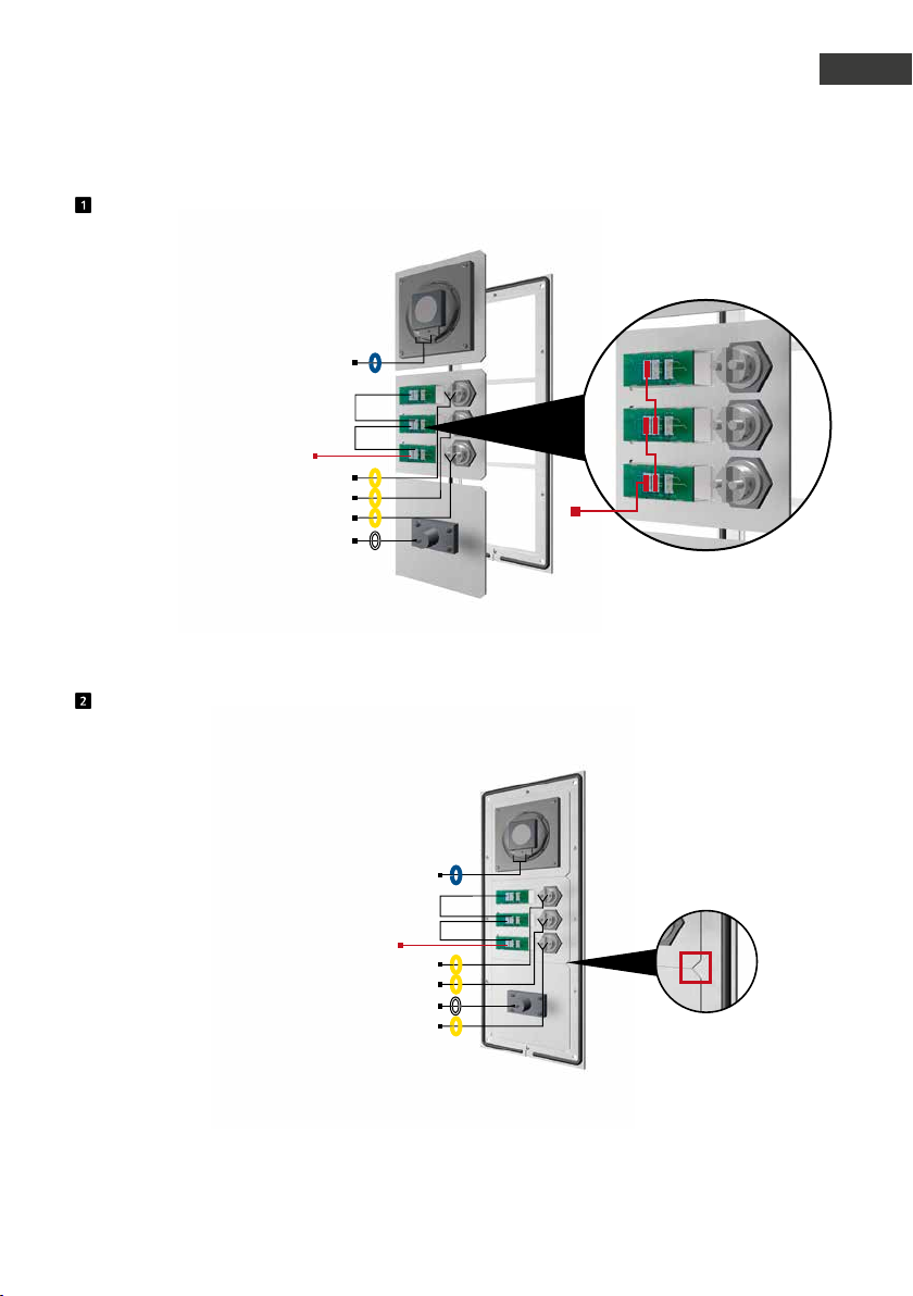
Funktionsmodule in Frontrahmen einlegen
LP
Brücken
Beleuchtung 12 V=
RT
T
RT
T
RT
T
Mik
Legen Sie die Module rückseitig in den Rahmen ein.
Anleitung Behnke SIP 2.0
Einleitung
Beleuchtung 12 V=
12 V-Brücken zur Beleuchtung
der Beschriftungsfelder
D
Funktionsmodule in Frontrahmen
LP
Beleuchtung 12 V=
RT
T
RT
T
Mik
RT
T
Achten Sie beim Einlegen der Module bitte unbedingt auf den Verdrehschutz sowie darauf, dass
die Module mit einem hörbaren "Klick" einrasten.
7www.behnke-online.de
Page 8
Anleitung Behnke SIP 2.0
D
Einleitung
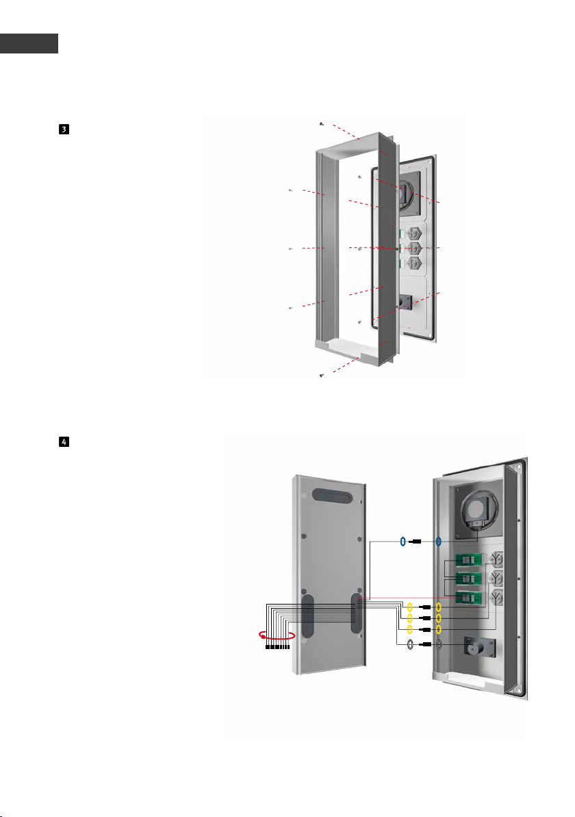
Modulgehäuse befestigen
Befestigen Sie das Modulgehäuse
am Frontrahmen.
Elektronikbox Modulgehäuse
Steckerbelegung Anschlussleitung
Serie 20, 30, 50:
LP (Blau) ▸ Lautsprecher
Mik (Weiß) ▸ Mikrofon
T1 bis T8 (Gelb) ▸ Taste 1 bis 8
Beleuc htung 12 V=
T1
T2
T3
T
T
T
12-poliger Stecker ▸ Tastwahlblock
Vorhandene Komponenten mit Flachbandleitung verbinden. Binden Sie die
nicht benötigten Leitungen mit einem
Kabelbinder zusammen (Stecker zeigen
nach unten).
8 www.behnke-online.de
Page 9
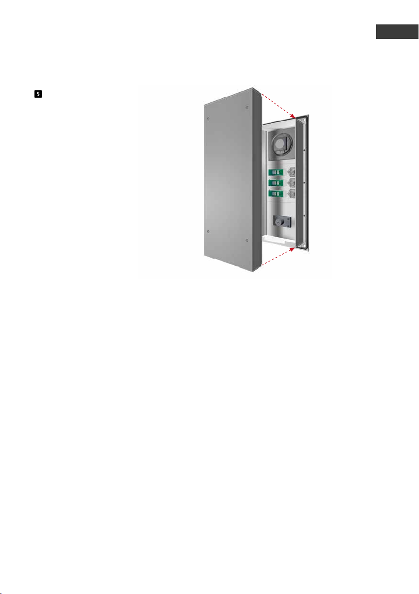
Klipsen Sie die Elektronikbox
wieder auf das Modulgehäuse auf.
Anleitung Behnke SIP 2.0
Einleitung
D
www.behnke-online.de
9
Page 10
Anleitung Behnke SIP 2.0
D
Einleitung
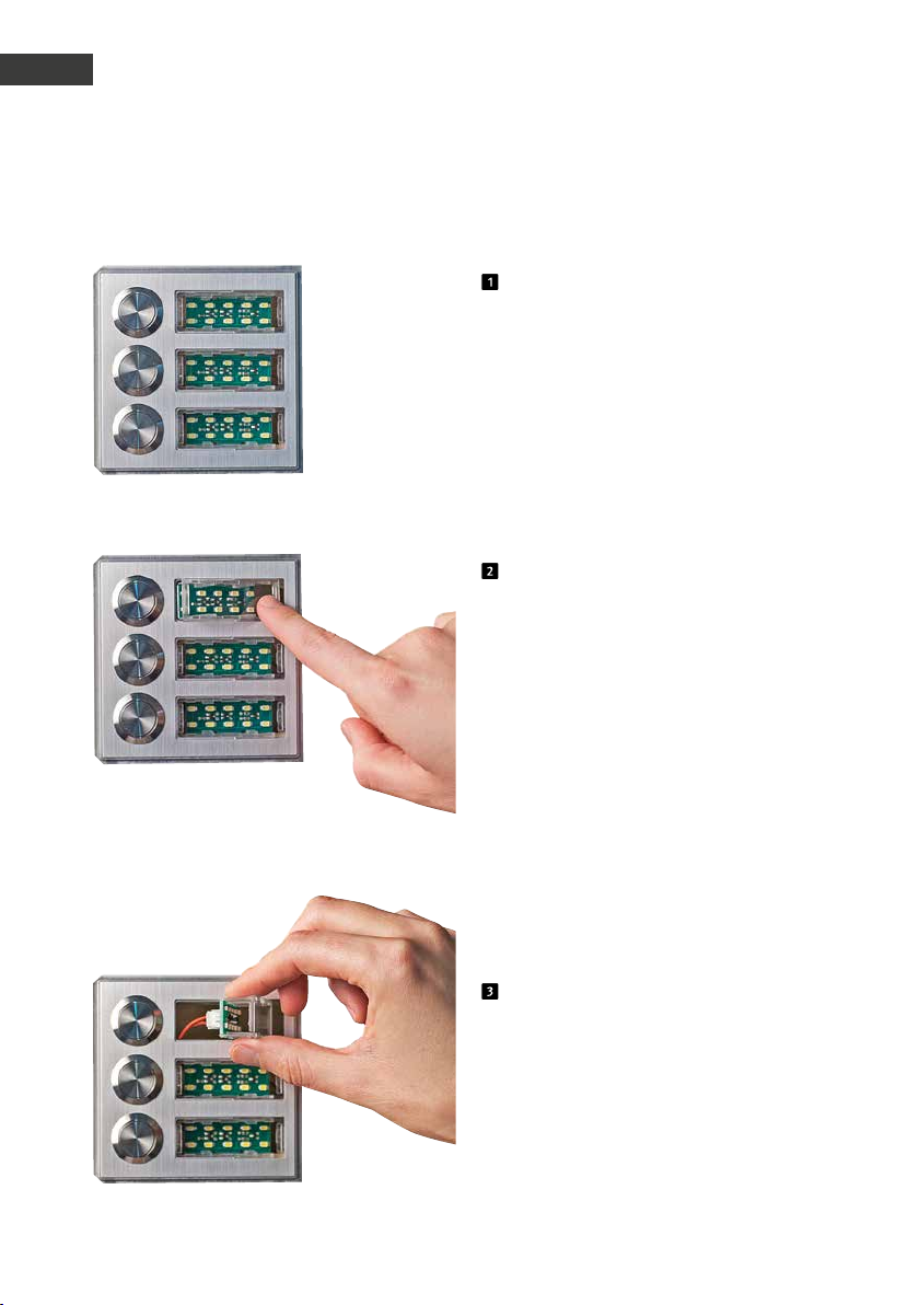
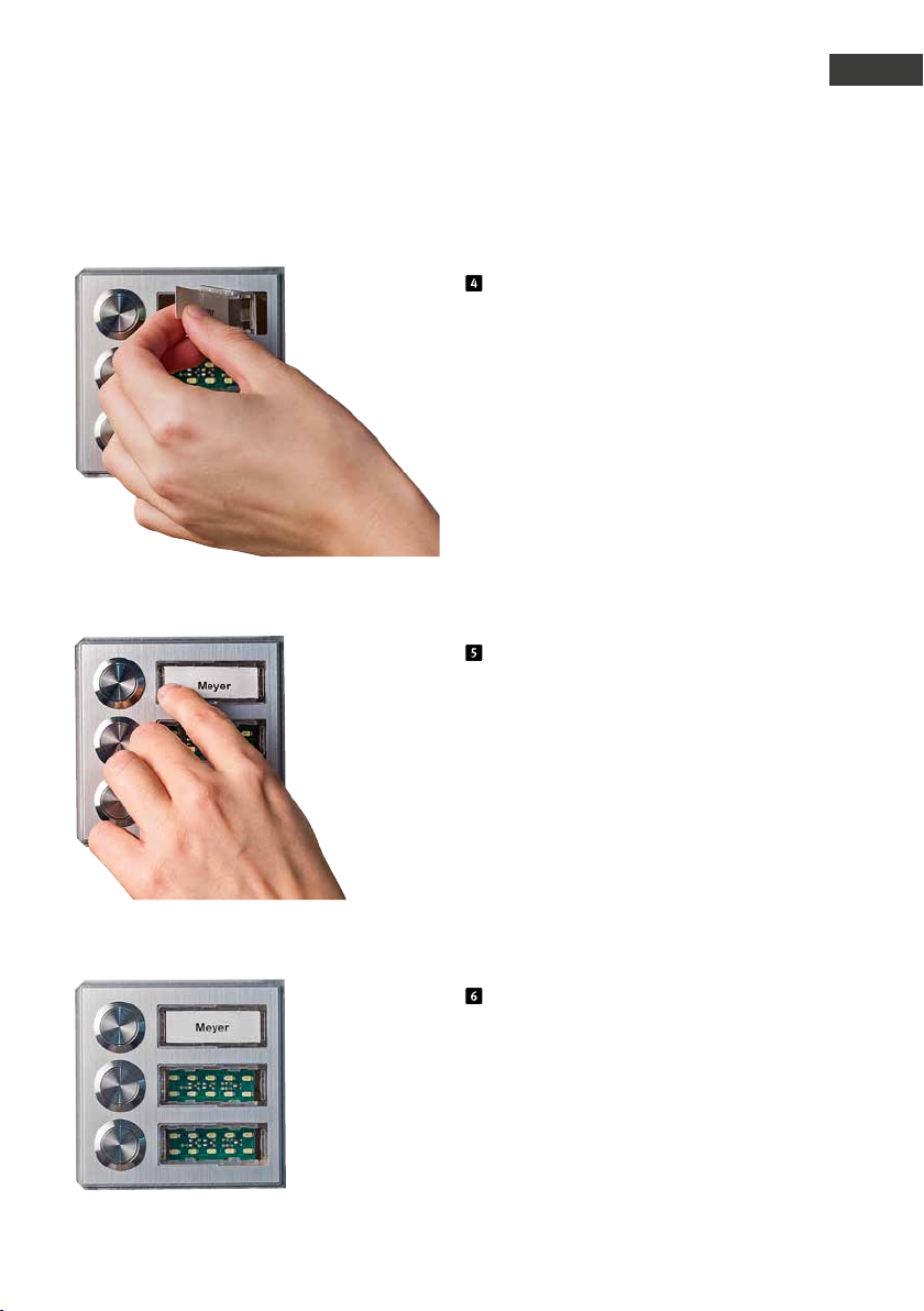
1.4. Beschriftetes Etikett einlegen
Auslieferungszustand
Beschriftungsfeld durch Druck auf die
rechte Seite lösen
und herausdrehen
10 www.behnke-online.de
Page 11
Anleitung Behnke SIP 2.0
Einleitung
Das beschriftete Etikett von links einlegen
Das Beschriftungsfeld links anlegen und
einrasten lassen
D
Fertig!
11www.behnke-online.de
Page 12
Anleitung Behnke SIP 2.0
D
Hardware
2.
hardware
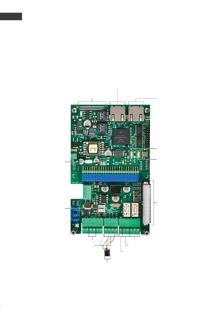
2.1. Basiselektronik Serie 20, 30, 40, 50
Erweiterungsanschluss
LEDs:
Rot: Stromversorgung
Blau: bereit
Grün: registriert
LAN-Anschluss INPUT
(SIP-Sprechstelle)
LAN-Anschlus s PORT 2
(Ans chluss für weitere
IP-Geräte, wie z. B .
IP-Kamera)
T1
T2
Stecker für
Modulbeleuchtung
(12 V)
Ethernetanschluss nach
EIA / TIA 568 A
Alarmeingang
Erde
1: weiß -grün
2: grün
3: weiß-orange
6: orange
Relais 2, Wechselkontakt
Relais 1 , Schließer
Anschlussleitung
für Funktionsmodule
12 www.behnke-online.de
Page 13
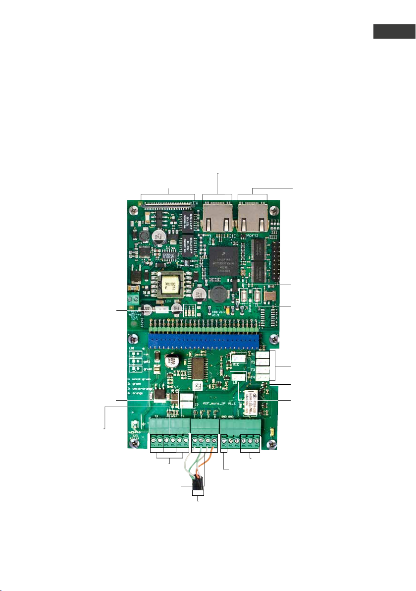
2.2. Kompaktgeräte Serie 10
Erweiterungsanschluss
LEDs:
Rot: Stromversorgung
Blau: bereit
Grün: registriert
LAN-Anschluss INPUT
(SIP-Sprechstelle)
Anleitung Behnke SIP 2.0
Hardware
LAN-Anschlus s PORT 2
(Ans chluss für weitere
IP-Geräte, wie z. B .
IP-Kamera)
T1
T2
D
Stecker für
Modulbeleuchtung
(12 V)
Alarmeingang
Alternativ-Anschluss
Ruftaste 3 + 4
Ethernetanschluss nach
EIA / TIA 568 A
Erde
1: weiß -grün
2: grün
3: weiß-orange
6: orange
Anschlussbereich
für Ruf tasten
Mikrofon
Lautsprecher
Relais 1, Wechselkontakt
13www.behnke-online.de
Page 14
Anleitung Behnke SIP 2.0
D
Hardware
2.3. Anschlüsse
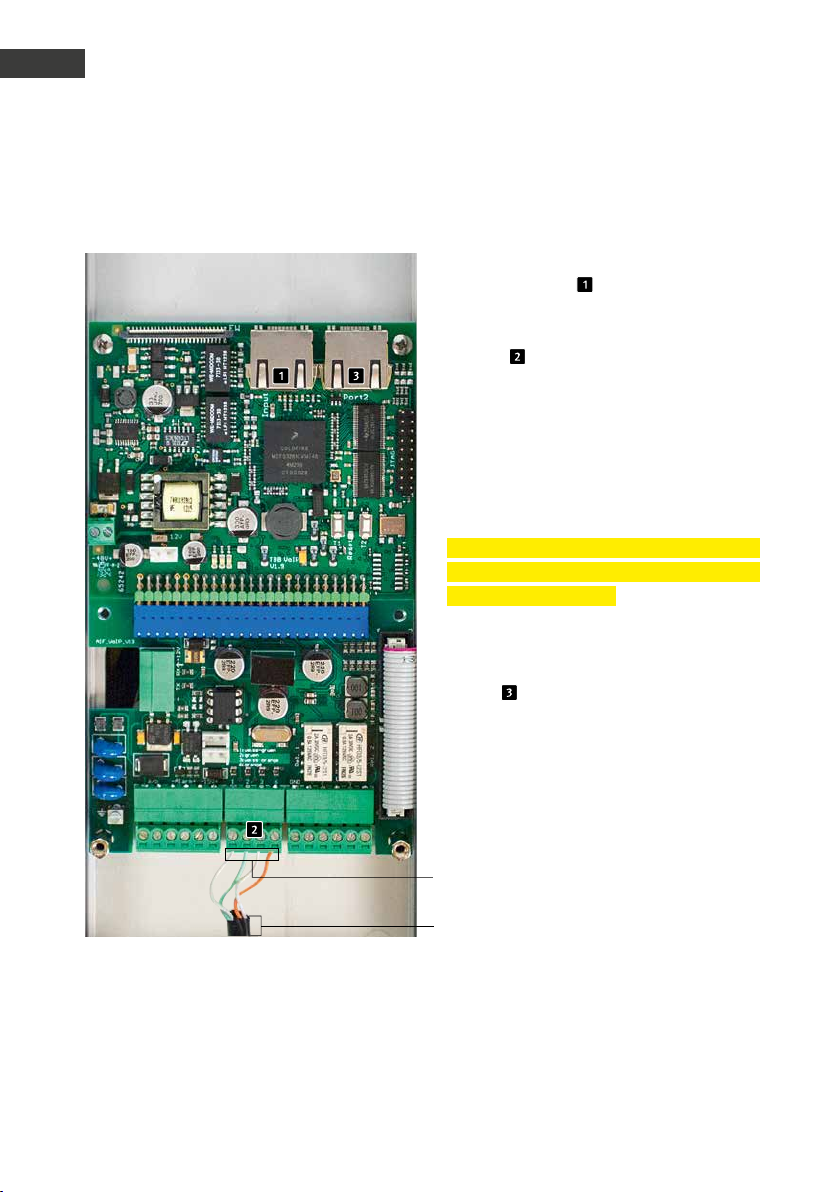
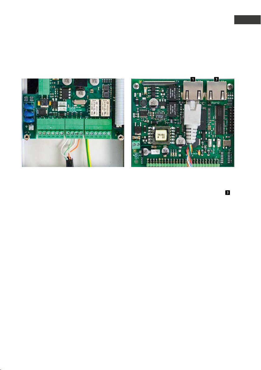
LAN-Anschluss - INPUT
Der LAN-Anschluss erfolgt üblicherweise über
einen RJ45-Stecker ( „INPUT“). Alternativ
lassen sich die einzelnen Adern aber auch
mittels Klemmleiste am Anschlussinterface
anbinden : Das Netzwerk wird auf die mit
1(weiß-grün), 2(grün), 3(weiß-orange) und
6(orange) bezeichneten Klemmen nach EIA/TIA
568 A angeschlossen. Die Zahl bezeichnet die
Pin-Nummer des RJ45-Steckers/der RJ45-Dose.
Achtung:
Beachten Sie bitte, dass der Anschluss ausschließlich über RJ45-Stecker oder Schraubklemmen erfolgen darf!
Für den Anschluss weiterer Endgeräte (z.B.
IP-Kamera) ist die zweite RJ45-Buchse
(PORT2) vorgesehen.
Ethernetanschluss nach
EIA / TIA 568 A
1: weiß -grün
Ethernetanschluss nach
EIA / TIA 568 A
2: grün
3: weiß-orange
6: orange
14 www.behnke-online.de
Page 15
Energieversorgung LAN-Anschluss PORT2
Anleitung Behnke SIP 2.0
Hardware
D
Die Energieversorgung erfolgt ausschließlich über PoE nach IEEE802.3af. Wenn die
Sprechstelle mittels Schraubklemme angebunden ist, so muss das stromgebende Gerät
Phantomspeisung unterstützen (Energieversorgung über die Adern 1, 2 und 3, 6, z.B. der
Behnke PoE-Injektor).
Der 2. Ethernet-Port wird über eine weitere
RJ45-Buchse mit der Beschriftung „Por t2“
kontaktiert.
Da die SIP-Sprechstelle über einen
POE-speisenden Switch verfügt, kann an
diesen Port ein POE-fähiges Endgerät mit
einer max. Leistungsaufnahme von 7 W angeschlossen werden.
Achtung: Für den 2. Ethernet-Port gibt es
keine Schraubklemmen.
15www.behnke-online.de
Page 16
Anleitung Behnke SIP 2.0
D
Hardware
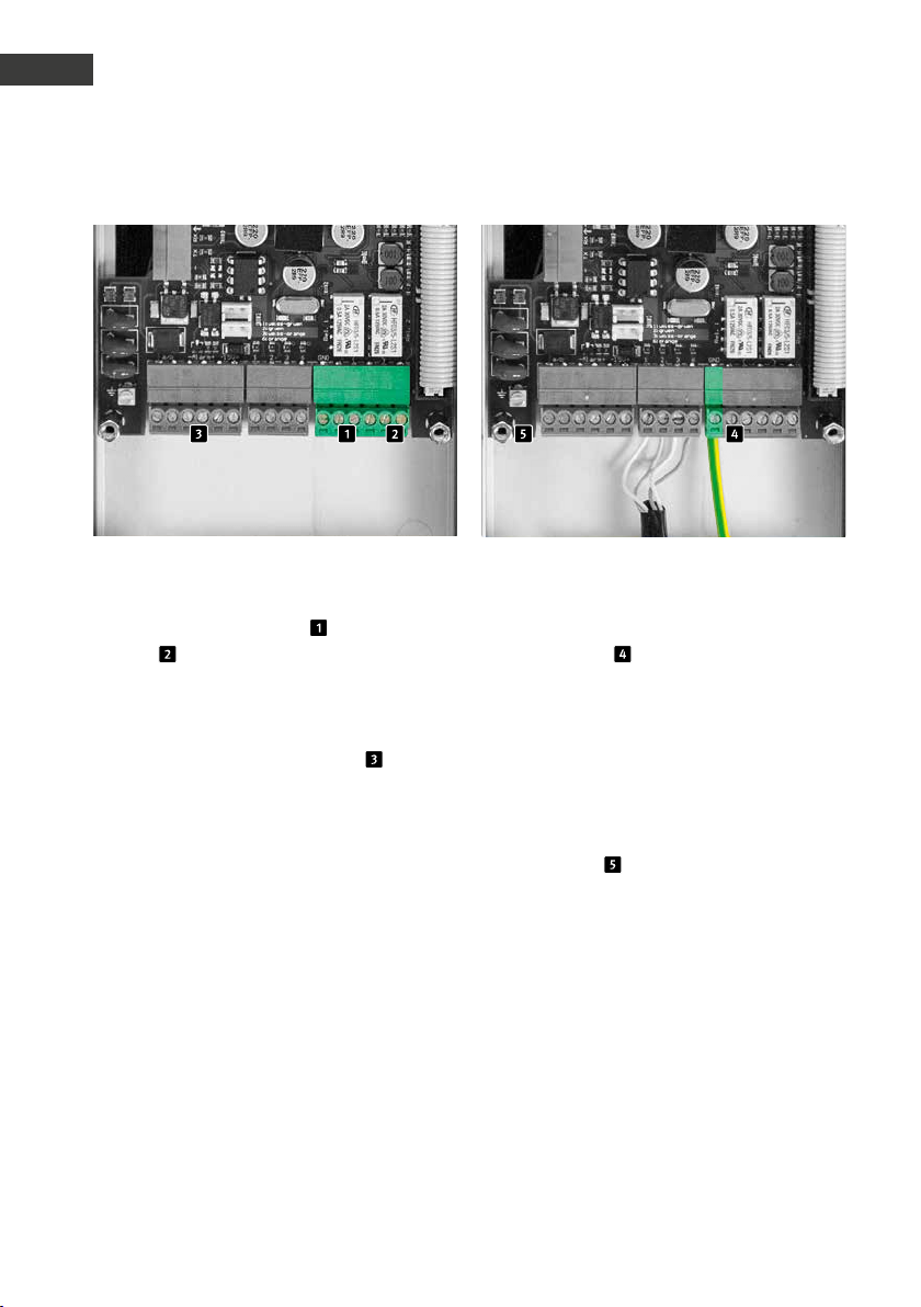
Potentialfreie Ausgänge (Relais), Eingänge Erdanschluss
Die SIP-Sprechstelle kann bis zu zwei potentialfreie Ausgänge (Relais 1 , Schließer ,
Relais 2 , Wechselkontakt) über Schraubklemmen zur Verfügung stellen. Weiterhin
stellt die SIP-Sprechstelle einen potentialgetrennten Eingang zur Verfügung, welcher über
Schraubklemmen kontaktier t wird .
Die Relais schalten maximal 2 A bei 30VDC
oder 0,5 A bei 40VAC.
Der Alarmeingang löst bei dem Anlegen einer
Eingangsspannung zwischen 10 und 15 V=
aus, die maximale Eingangsspannung beträgt
15 V=. Bitte Polarität beachten!
Achtung: Wenn es sich um einen TNV-1 Stromkreis handelt, ist eine ERDE an die GNDSchraubklemme anzuschließen. Um einen
TNV-1 Stromkreis handelt es sich in der Regel
bei Installationen in einer Säule, da hier
das Ethernetanschlusskabel außerhalb des
Gebäudes verlegt ist. Bleibt das Eternetkabel
innerhalb eines Gebäudes, muss die SIPSprechstelle nicht geerdet werden.
Die Erdklemme darf hier nicht verwendet
werden.
16 www.behnke-online.de
Page 17
Anleitung Behnke SIP 2.0
Hardware
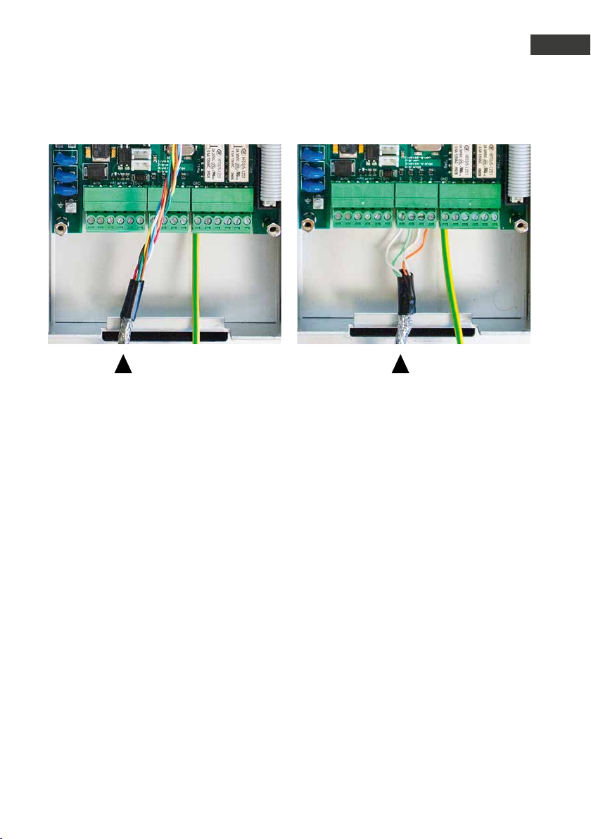
Schirmung
Legen Sie die Schirmung des geerdeten Ethernet-Kabels, wie im Bild dargestellt, am unteren
Gehäusesteg auf.
D
17www.behnke-online.de
Page 18

Anleitung Behnke SIP 2.0
D
Konfiguration und Inbetriebnahme
3.
konfiguration und inbetriebnahme
Vorbereitung
Verbindung der SIP-Sprechstelle mit einem
▸
10/ 100 Mbit Ethernet LAN
Stromversorgung via Power over Ethernet
▸
(PoE nach IEEE 802.3af))
Die Behnke SIP-Sprechstelle ist werkseitig auf
automatische IP-Konfiguration via DHCP konfiguriert. Sie bezieht ihre IP-Adresse automatisch vom DHCP-Server, soweit vorhanden. Mit
den Tasten T1 und T2 auf der Basiselektronik
kann dieses Verhalten umgeschaltet werden:
Nach dem Herstellen der Stromversorgung
dauert es ca. 90 Sekunden bis ein dunkler
Bestätigungston ertönt. Dieser signalisiert die
Bereitschaft der Sprechstelle.
Achtung: Wenn die SIP-Sprechstelle an ein
neues Netz angeschlossen wird, so kann es
bis zu 3 Minuten dauern, bis diese vom DHCPServer eine neue IP-Adresse zugewiesen
bekommt.
Nun kann die IP-Adresse der Sprechstelle
über das Sprachmenü ermittelt werden:
1. Taste T1 drücken, es ertönt „Sprache
Deutsch“
2. Taste T2 drücken, es ertönt „IP-Adresse
ausgeben“
3. Taste T2 drücken, die IP-Adresse der
Sprechstelle wird angesagt
Wenn kein DHCP-Server vorhanden ist, so
kann die IP-Adressvergabe auf „statisch“
umgestellt werden:
1. Taste T1 drücken, es ertönt „Sprache
Deutsch“
2. Taste T2 drücken, es ertönt „IP-Adresse
ausgeben“
3. Taste T1 drücken, es er tönt „IP-Adress-
vergabe einstellen“
4. Taste T2 drücken, es ertönt „dynamisch“
5. Taste T1 drücken, es ertönt „statisch“
6. Taste T2 drücken, um die Auswahl zu
bestätigen
Die SIP-Sprechstelle ist nun auf die stati-
sche IP-Adressvergabe mit der IP-Adresse
192 .168.100.100 und der Subnetzmaske
255.255.255.0 konfiguriert.
Nun setzen Sie die Konfiguration über das
Web-Frontend fort, dieses ist durch SSL-Verschlüsselung abgesichert (https). In der SIPSprechstelle ist ein vom Hersteller selbst signiertes SSL-Zertifikat installiert, das zu einer
Sicherheitswarnung bei gängigen Browsern
führt. Durch „Laden dieser Webseite fortsetzen (nicht empfohlen)“ können Sie dennoch
auf die Konfigurationsoberfläche zugreifen.
Um diese Abfrage künftig zu umgehen, kann
das Zertifikat auch lokal im Browser abgespeichert werden. Dieser Prozess ist jedoch von
Browser zu Browser unterschiedlich, sodass
hier keine allgemeingültige Vorgehensweise
angegeben werden kann.
18 www.behnke-online.de
Page 19
Anleitung Behnke SIP 2.0
Konfiguration und Inbetriebnahme
D
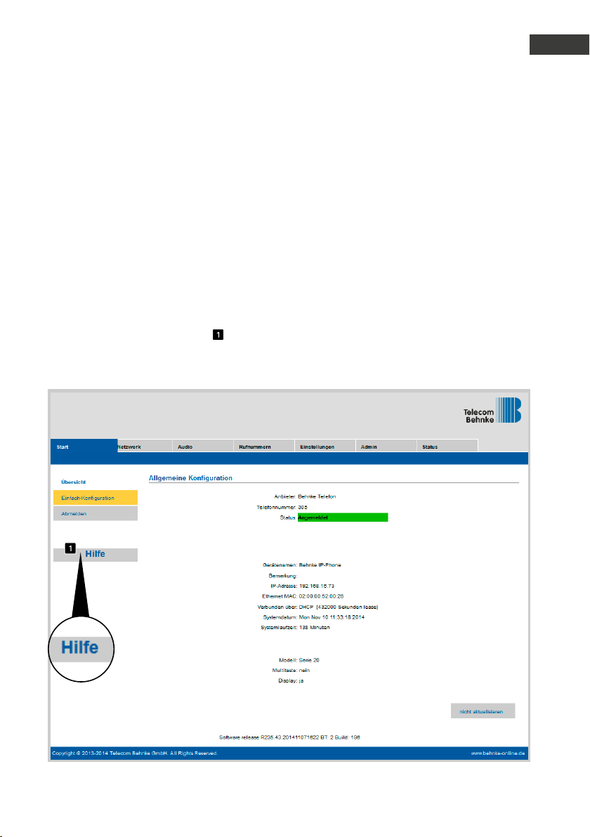
Wenn nun der Begrüßungsbildschirm
erscheint, gelangen Sie durch Klicken auf
„Anmelden“ zur Passwortabfrage. Die Standardeinstellungen lauten:
Benutzername: admin
•
Passwort: admin
•
Nun erscheint die Statusanzeige der Behnke
SIP-Sprechstelle. Die Online-Hilfe ist hier
jederzeit über den „Hilfe“-Knopf
linken Spalte zu erreichen.
in der
Anmerkung: In einer Verbindung kann die
Lautstärke durch Drücken der Tasten am Telefon wie folgt eingestellt werden:
##1 + Lautstärke von 1-9
▸
##2 + Mikrofonempfindlichkeit von 1-9
▸
Beispiel:
Lautstärke auf 5 einstellen:
▸
##15
Mikrofonempfindlichkeit auf 7 einstellen:
▸
##27
19www.behnke-online.de
Page 20
Anleitung Behnke SIP 2.0
D
Autoprovisionierung
4.
autoprovisionierung
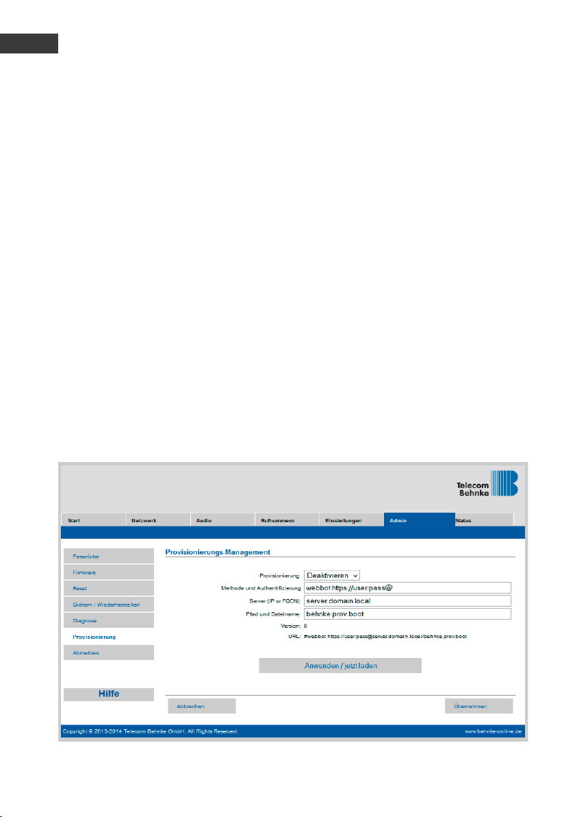
Mit der Autoprovisionierung kann die Behnke
SIP-Sprechstelle vollautomatisch konfiguriert
werden. Alle über das Web-Frontend zugänglichen Parameter einschließlich der Telefonbücher lassen sich mit der Autoprovisionierung
einrichten. Die Behnke SIP-Sprechstelle unterstützt zwei Arten der Autoprovisionierung:
1. Vollautomatisch mittels DHCP Option 66
Hierzu wird die Option 66 im DHCP-Server
konfiguriert, wo die Konfigurationsdatei zu
finden ist.
Die Behnke SIP-Sprechstelle unterstützt den
Download von http, https oder ftp-Servern.
Beispiel für eine gültige Option 66:
ftp://192.168.30.2/behnke/
In diesem Ordner muss eine Datei mit folgendem Dateinamen liegen:
<MAC-Adresse>.txt
hierbei ist <MAC-Adresse> die Hexadezimal
notierte MAC-Adresse; wie sie auch im WebFrontend unter „Status“ angezeigt wird, jedoch
ohne Doppelpunkte.
2. Halbautomatisch mittels einstellbarem
Konfigurationsserver
Hier können Sie im Web-Frontend unter „Autoprovisionierung“ einstellen, welche Konfigurationsdatei die Sprechstelle von welchem
Konfigurationsserver herunterlädt.
20 www.behnke-online.de
Page 21
5.
reset auf werkseinstellungen
Anleitung Behnke SIP 2.0
Reset auf Werkseinstellungen
D
Um ein Reset auf Werkseinstellung durchzuführen, führen Sie folgende Schritte aus:
SIP-Sprechstelle stromlos schalten
▸
Tasten T1 und T2 gemeinsam drücken und
▸
gedrückt halten
Sprechstelle wieder mit Strom versorgen
▸
Tasten T1 und T2 solange gedrückt halten
▸
bis zwei LEDs (grün, blau) im Sekundentakt
blinken
Tasten T1 und T2 loslassen
▸
Reset auf Werkseinstellung wird ausgeführt,
▸
Dauer ca. 90 Sekunden
Reset wurde erfolgreich durchgeführ t, nachdem ein Bestätigungston aus dem Lautsprecher ausgegeben wurde.
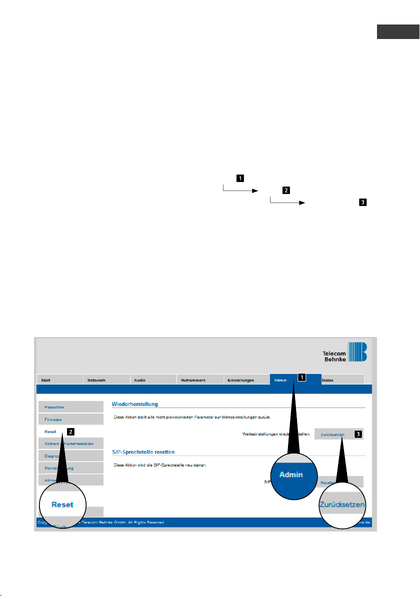
Das Web-Interface bietet eine weitere Möglichkeit, das Gerät auf Werkseinstellungen
zurückzusetzen, im Folgenden sind die diesbezüglichen Schritte aufgeführt:
Admin
Reset
Zurücksetzen
21www.behnke-online.de
Page 22

Anleitung Behnke SIP 2.0
D
Technische Daten
6.
technische daten
Alle Sprechstellen
Status-/Fernsteuermeldungen zur Integra-
▸
tion mit Fremdsoftware
9 Sprachansagen mit je bis zu 40 Sekunden
▸
Länge speicherbar
16 MB gemeinsamer Flash-Speicher für Tele-
▸
fonbuch und Sprachansagen
Konfiguration in Datei speicherbar
▸
Netzwerk
MAC-Adresse (IEEE 802.3)
▸
IPv4 – Internet Protocol Version 4 (RFC 791)
▸
ARP – Address Resolution Protocol
▸
DNS – A record (RFC 1706)
▸
DHCP Client – Dynamic Host Configuration
▸
Protocol (RFC 2131)
TCP – Transmission Control Protocol (RFC 93)
▸
UDP – User Datagram Protocol (RFC 768)
▸
RTP – Real Time Protocol (RFC 1889)
▸
(RFC 1890)
RTCP – Real Time Control Protocol (RFC 1889)
▸
DiffServ (RFC 2475), Type of Service
▸
(RFC 791, RFC 1349)
SNTP – Simple Network Time Protocol
▸
(RFC 2030)
SIPv2 – Session Initiation Protocol Version 2
▸
(RFC 3261, 3262,3263, 3264)
SIP in NAT-Netzwerken (STUN)
▸
Autoprovisionierung via DHCP Option 66
▸
oder per konfiguriertem Server
Backup-SIP-Server konfigurierbar
▸
Firmware-Update via Web-Interface
▸
Integrierter POE-Switch mit Unterstützung für
▸
Tagged VLANs
Sprachcodecs
G.711 (A-law, μ-law)
▸
G726 (32 kbps)
▸
G.721
▸
DTMF In-Band, Out-of-Band und SIP-Info
▸
(RFC 2833)
Vollduplex, Echo-Unterdrückung (AEC)
▸
Lautsprecherlautstärke in 10 Stufen konfi-
▸
gurierbar
Mikrofonempfindlichkeit in 10 Stufen konfi-
▸
gurierbar
Serie 10 IP
Kompaktgerät mit integriertem Lautsprecher
▸
und Mikrofon
Ein oder zwei Ruftasten mit beleuchteten
▸
Beschriftungsfeldern
Ein frei konfigurierbares Relais
▸
Serie 20 IP
Modularer Aufbau
▸
Bis zu 8 Direktruftasten mit frei konfigurier-
▸
baren Rufnummern
Zwei frei konfigurierbare Relais
▸
Optionales Sicherheitsrelais zur abgesetzten
▸
Montage erhältlich
Modul Tastwahlblock verfügbar, Funktionen:
▸
Direkte Rufnummernanwahl
•
Codeschloss
•
Kurzwahl mit bis zu 100 Zielen
•
Modul Display verfügbar, Funktionen
▸
Beleuchtet
•
Vier Zeilen mit je 20 Zeichen
•
Infotexte je nach Gerätezustand,
•
konfigurierbar
199 Telefonbucheinträge, mehr auf Anfrage
•
Multitaste mit 100 Ruftasten auf Anfrage
▸
22 www.behnke-online.de
Page 23

Anleitung Behnke SIP 2.0
Technische Daten
D
Sicherheit und Administration
Passwortschutz für Admin-Zugriff
▸
Web-Browser gestützte Administration
▸
Physikalische Anschlüsse
RJ45-Port für 100baseT Ethernet, alternativ
▸
mittels Schraubklemme
Schraubklemmen für die Kontaktierung der
▸
Relais
Elektrische Charakteristika
Stromversorgung via Power over Ethernet (PoE
▸
nach IEEE 802.3af)
Max. Leistungsaufnahme: 12 W
▸
SIP Sprechstelle: 5 W
▸
Gerät an PORT2: max. 7 W
▸
Max. Schaltleistung der Relais:
▸
2 A /30VDC
0.5 A /40VAC
Eingangsspannung Alarmeingang:
▸
10 V bis max. 15 V
Betriebstemperatur: -20° C bis +50° C
▸
TNV-1: Bei TNV-1 Stromkreisen muss die SIP-
▸
Sprechstelle über den GND-Anschluss geerdet werden, siehe Kapitel 2.3. Anschlüsse,
Erdanschluss
EMV: EN55022 A /B, EN55024
▸
Safety: EN60950
▸
23www.behnke-online.de
Page 24
Anleitung Behnke SIP 2.0
D
CE-Erklärung
7. ce-
erklärung
24 www.behnke-online.de
Page 25

8.
rechtliche hinweise
Anleitung Behnke SIP 2.0
Rechtliche Hinweise
Infos zum Produkthaftungsgesetz:
D
1. Änderungen an unseren Produkten, die dem
technischen Fortschritt dienen, behalten wir
uns vor. Die abgebildeten Produkte können im
Zuge der ständigen Weiterentwicklung auch
optisch von den ausgelieferten Produkten
abweichen.
2. Abdrucke oder Übernahme von Texten,
Abbildungen und Fotos in beliebigen Medien
aus dieser Anleitung – auch auszugsweise –
sind nur mit unserer ausdrücklichen schriftlichen Genehmigung gestattet.
3. Die Gestaltung dieser Anleitung unterliegt
dem Urheberschutz. Für eventuelle Irrtümer,
sowie inhaltliche bzw. Druckfehler (auch bei
technischen Daten oder innerhalb von Grafiken und technischen Skizzen) übernehmen
wir keine Haftung.
1. Alle Produkte aus dieser Anleitung dürfen
nur für den angegebenen Zweck verwendet
werden. Wenn Zweifel bestehen, muss dies
mit einem kompetenten Fachmann oder unserer Serviceabteilung (siehe Hotline-Nummern)
abgeklärt werden.
2. Produkte, die spannungsversorgt sind (ins-
besondere 230 V-Netzspannung), müssen vor
dem Öffnen oder Anschließen von Leitungen
von der Spannungsversorgung getrennt sein.
3. Schäden und Folgeschäden, die durch Ein-
grif fe oder Änderungen an unseren Produkten
sowie unsachgemäßer Behandlung verursacht
werden, sind von der Haf tung ausgeschlossen. Gleiches gilt für eine unsachgemäße
Lagerung oder Fremdeinwirkungen.
4. Beim Umgang mit 230 V-Netzspannung oder
mit am Netz oder mit Batterie betriebenen
Produkten, sind die einschlägigen Richtlinien
zu beachten, z. B. Richtlinien zur Einhaltung
der elektromagnetischen Verträglichkeit oder
Niederspannungsrichtlinie. Entsprechende
Arbeiten sollten nur von einem Fachmann
ausgeführt werden, der damit vertraut ist.
Elektromagnetische
Verträglichkeit
Niederspannungsrichtlinie
5. Unsere Produkte entsprechen sämtlichen,
in Deutschland und der EU geltenden, technischen Richtlinien und Telekommunikationsbestimmungen.
25www.behnke-online.de
Page 26

Anleitung Behnke SIP 2.0
D
Notizen
26 www.behnke -online.de
Page 27

instructions
D SIP-Sprechstellen Seite .........3
GB SIP intercoms Page ....... 29
F Postes téléphoniques SIP Page ........ 55
Version 2.3
Page 28

Instructions for Behnke SIP 2.0
GB
Contact
Important information
Please note that Behnke intercoms and accessories may only be installed and serviced by
qualified electricians in compliance with the
relevant safety provisions.
contact
Information
For detailed information on our product,
projects and services:
Tel.: +49 (0) 68 41/81 77-700
24-hour-service
Do you need help? Feel free to contact us
24/7. We will be happy to assist you with
any technical questions you may have
and we will also help you getting set-up.
Tel.: +49 (0) 68 41/81 77-777
Before carrying out service and maintenance
work, please ensure that the devices are safely
disconnected from the power grid (unplug
power supply unit) and are disconnected from
any other network or phone connection.
For further legal information, please see
page 51.
Telecom Behnke GmbH
Gewerbepark „An der Autobahn“
Robert-Jungk-Straße 3
D-66459 Kirkel
Internet and email address
www.behnke-online.de
[email protected]
28 www.behnke-online.com
Page 29

Instructions for Behnke SIP 2.0
Contents
contents
1. Introduction 30
1.1. Whatʼs in the box ........................................................................................................... 30
1.2. General Information ...................................................................................................... 30
1.3. Series 20 and 30 remote station installation ................................................................. 32
1.4. Insert printed label ...................................................................................................... 36
2. Hardware 38
2.1. Series 20, 30, 50 basic electronics ................................................................................ 38
2.2. Series 10 compact devices ............................................................................................ 39
2.3. Connections .................................................................................................................40
3. Configurations and set-up 44
4. Auto-Provisioning 46
5. Reset to default settings 47
GB
6. Technical Specifications 48
7. CE Declaration 50
8. Legal Information 51
29www.behnke-online.com
Page 30

Instructions for Behnke SIP 2.0
GB
Introduction
1.
introduction
1.1. Whatʼs in the box
Basic electronics as a
▸
Series 20, 30, 50 electronics box or
•
Series 10 compact intercom
•
The present instructions
▸
1.2. General Information
Features
Behnke Series 20, 30 and 50 SIP remote
stations are high-quality modular VoIP
intercoms with acoustic echo suppression
offering exceptional audio quality and
full-duplex hands-free operation. Their
components, such as speakers, microphone,
keypad and call buttons, as well as the
electronics form a compact unit in a doublewalled housing. The modular design
enables utmost flexibility for planning
and implementation. Via the connected
Ethernet, the device uses Voice over IP (VoIP)
according to the SIP standard for establishing
communication, either making use of an SIPcompatible telephone system, an SIP provider
or by directly dialling an IP address. Use a
standard web browser for configurations
and software updates; your local network
provides power (PoE). It is possible to
externally connect direct call buttons to
the remote stations and to have switches
that may be freely configured to open the
door, display a call or hold any other switch
function. Use add-on modules to retrofit
additional functions, e.g. a 4 line display with
a telephone book function or up to 100 direct
call buttons.
30 w ww.behnke -online.com
Page 31

Instructions for Behnke SIP 2.0
Introduction
GB
Series 10 compact remote stations are highquality devices that come pre-assembled
with up to two call buttons. They also feature
acoustic echo suppression; so, these remote
stations are suitable for full-duplex hand-free
communications as well. They are also equipped with a relay to be configured according to
your needs.
System requirements
Minimum requirements to install Behnke SIP
remote stations:
PC or Apple® Macintosh® with browser
▸
(e.g. Microsoft® Internet Explorer®, Mozilla
Firefox®, Apple® Safari®)
Monitor/graphics with a resolution of at
▸
least 1024 x 768 pixels and true colour
display
Set-up network connection
▸
A free Ethernet port with PoE or a separate
▸
PoE injector.
An SIP account, an SIP server or a remote
▸
terminal to directly accept SIP connections.
Minimum system requirements to install
Behnkeʼs IP video software:
PC with Intel® Pentium® IV processor
▸
(1.7GHz) or AMD Athlon™ processor
(1.2GHz) or better
Network interface controller, configured
▸
Microsoft® Windows® 2000 or Windows® XP
▸
operating system or later
128 MB RAM or more
▸
Monitor/graphics with a resolution of at
▸
least 1024 x 768 pixels and true colour
display
31www.behnke -online.com
Page 32

Instructions for Behnke SIP 2.0
GB
Introduction
1.3. Series 20 and 30 remote station installation
Please note: For aesthetic appeal and moisture protection, please pay attention to the
correct alignment of the aluminium brushing!
In case you wish to install the electronics in a
detached location, please replace the module
housing with an open counter plate for the
appropriate front frame.
Connect the cables as follows:
1. Buttons (RT ) ▸ Connect to the MQS connec-
tors from 1 to 8 marked with
the yellow ring
2. Speakers (L S) ▸ Connect to the connector
marked with the blue ring
3. Microphone (mic) ▸Connect to the connec-
tor marked with the white ring
4. Keypad ▸ 12-pin white socket
Important: Do not confuse the connectors for
the speakers and the microphone!
Please put unused cables into the module
housing with the open end (connector) facing
down. Doing so will prevent moisture from
entering the connector. Now put the electronics box on top of the module housing.
32 www.behnke-online.com
Page 33
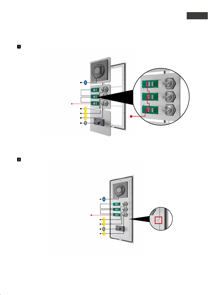
Insert the function modules into the front frame
LS
Bridge circuits
Illumination 12 V=
RT
T
RT
T
RT
T
Mic
From the rear, put the modules into the frame
Instructions for Behnke SIP 2.0
Introduction
Illumination
12 V=
12V bridge circuits to illuminate
the labels
GB
Function modules inside the front frame
LS
Illumination 12 V=
RT
T
RT
T
Mic
RT
T
When inserting the modules, please always pay attention to the anti-rotation element and
ensure that the modules latch into position with an audible "click".
33www.behnke-online.com
Page 34
Instructions for Behnke SIP 2.0
GB
Introduction
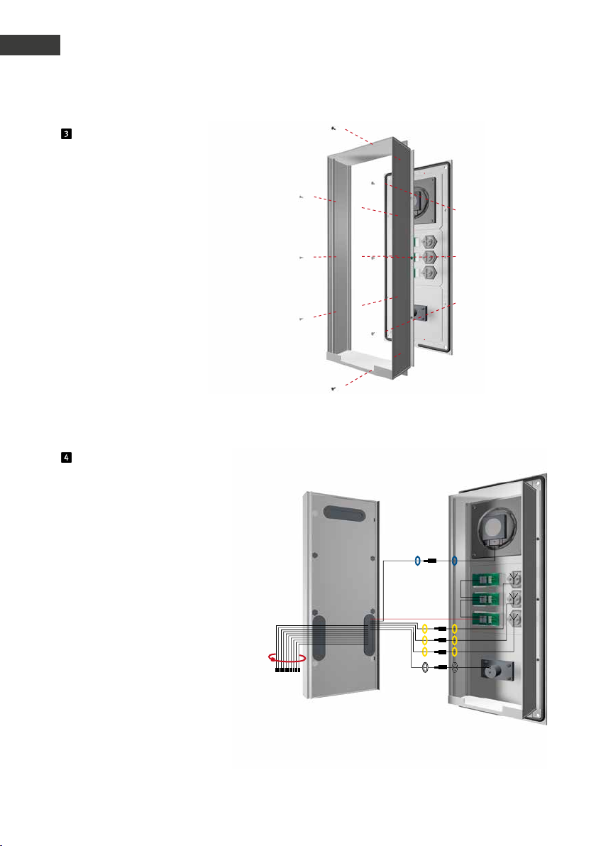
Fix the module housing
Fix the module housing onto
the front frame.
Electronics box Module housing
Connection cable pin assignment
Series 20, 30, 50:
LS (blue) ▸ Speakers
Mic (white) ▸ Microphone
T1 bis T8 (yellow) ▸ Buttons 1 to 8
Illumination 12 V=
T1
T2
T3
T
T
T
12-pin connector ▸ Keypad
Connect existing components using the
ribbon cable. Use a cable tie to bundle
unused wires (connectors facing down).
34 w ww.behnke-online.com
Page 35
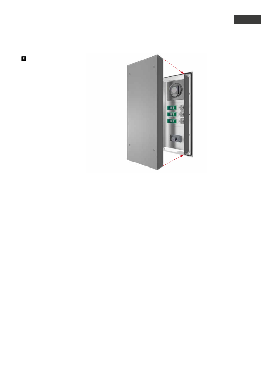
Clip the electronics box back
onto the module housing.
Instructions for Behnke SIP 2.0
Introduction
GB
35www.behnke-online.com
Page 36
Instructions for Behnke SIP 2.0
GB
Introduction
1.4. Insert printed label
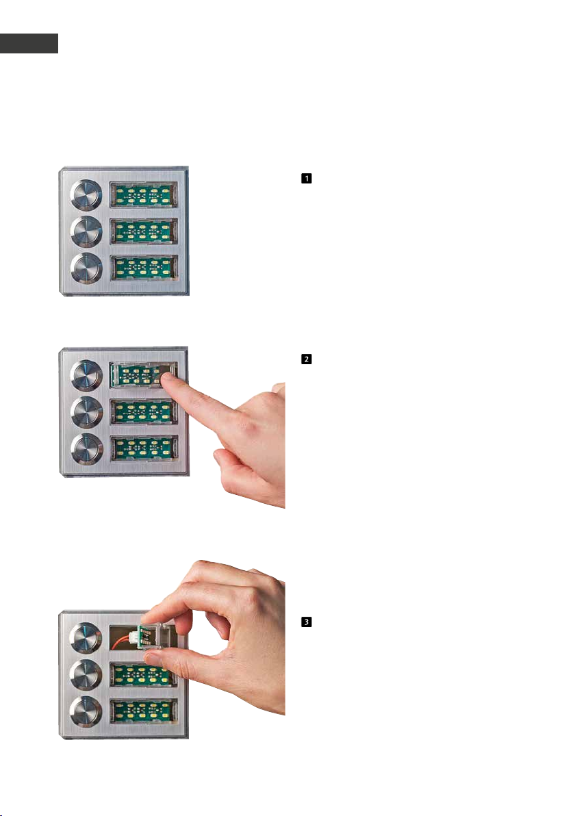
Condition as supplied to the customer
Press on the right-hand side to remove the
label holder
Retrieve the label holder
36 w ww.behnke-online.com
Page 37
Instructions for Behnke SIP 2.0
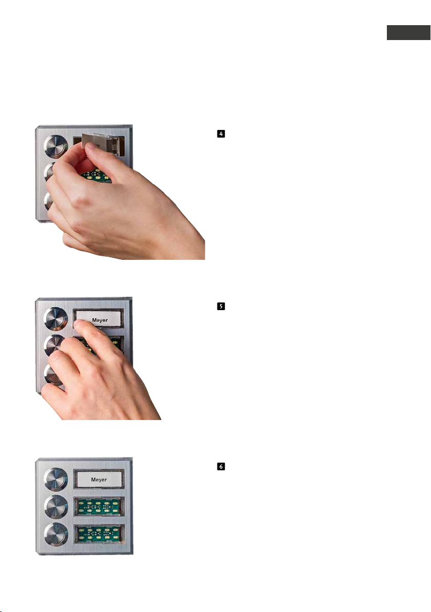
Introduction
Insert the printed label from the left
Return the label holder to its original posi-
tion from right to left; click into place
GB
Done!
37www.behnke -online.com
Page 38
Instructions for Behnke SIP 2.0
GB
Hardware
2.
hardware
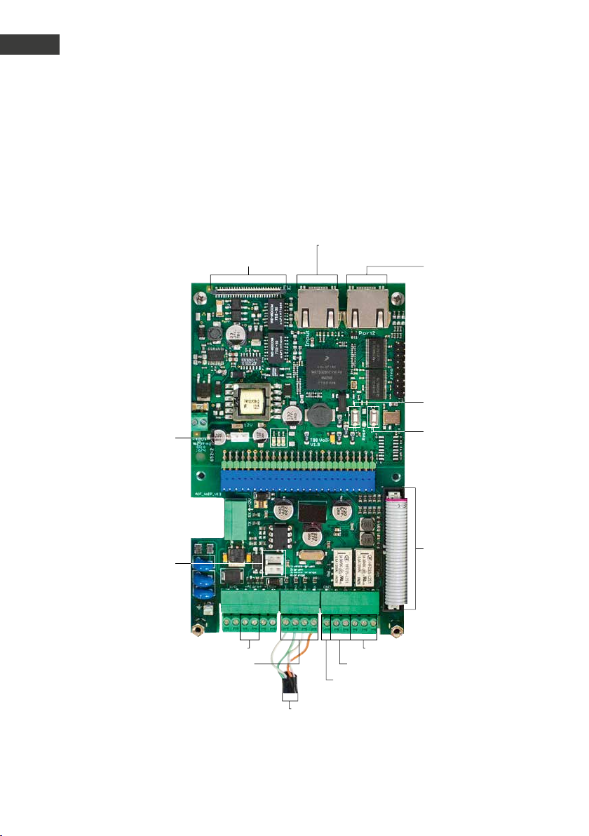
2.1. Series 20, 30, 50 basic electronics
Extension connec tion
LEDs:
Red: Power suppl y
blue: ready
green: registered
Network co nnection IN PUT
(SIP remote station)
Network co nnection PORT 2
(connection for additional
IP devices, e.g.
IP camera)
T1
T2
Connector for
module illumination
(12V)
Ethernet connection
according to
EIA/ TIA 568 A
Alar m input
Grounding
1: white-green
2: gre en
3: white-orange
6: orange
relay 2 , changeover contac t
relay 1, closing contact
Connection cable
for function modules
38 ww w.behnke-online.com
Page 39
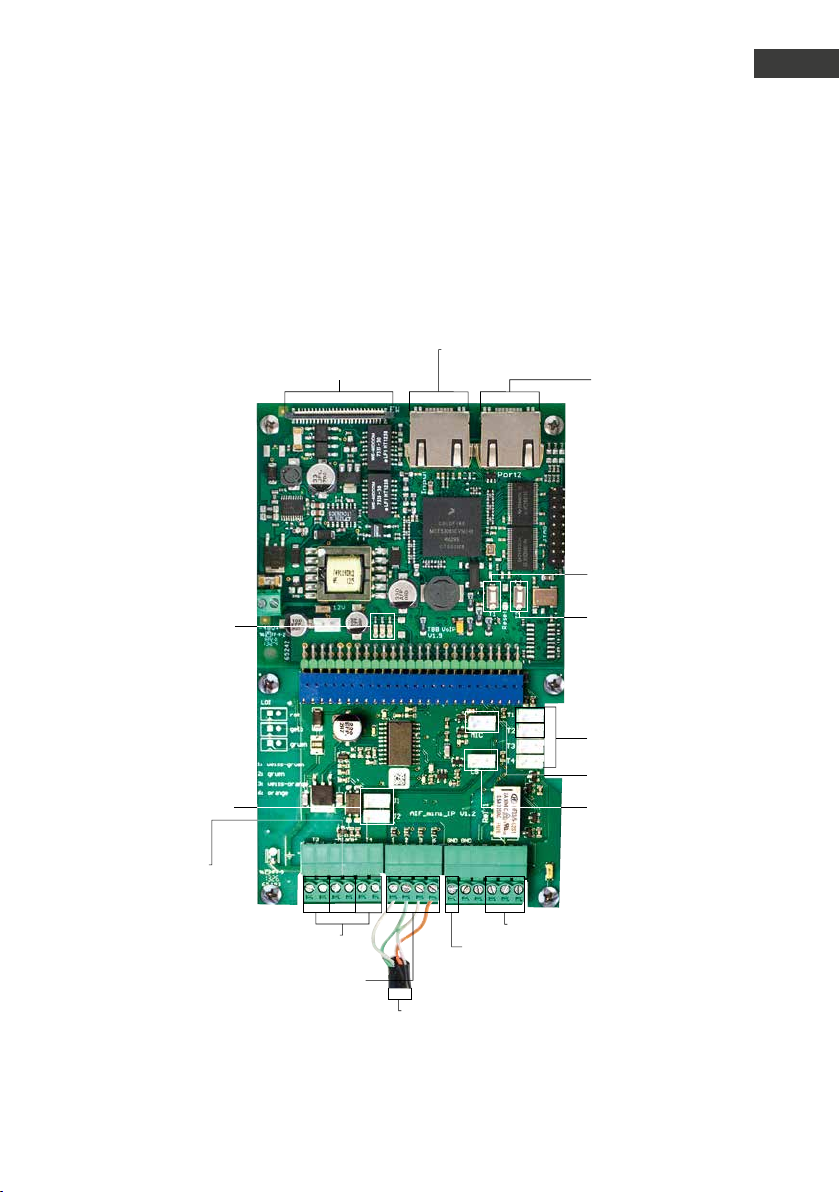
2.2. Series 10 compact devices
Extension connec tion
LEDs:
Red: Power suppl y
blue: ready
green: registered
Instructions for Behnke SIP 2.0
Network co nnection IN PUT
(SIP remote station)
Hardware
Network co nnection PORT 2
(connection for additional
IP devices, e.g.
IP camera)
T1
T2
GB
Connector for
module illumination
(12V)
Alar m input
Alternative connection,
call buttons 3 + 4
Ethernet connection
according to EIA /TIA 568 A
Grounding
1: white-green
2: gre en
3: white-orange
6: orange
Connection area
for call buttons
Microphone
Speakers
Relay 1, changeover contact
39www.behnke-online.com
Page 40
Instructions for Behnke SIP 2.0
GB
Hardware
2.3. Connections
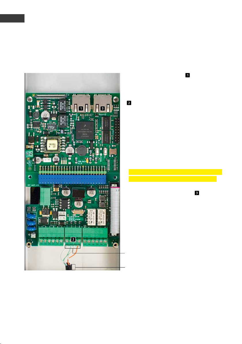
Network connection - INPUT
Usually, an RJ-45 connector ( “INPUT”) is
used to establish a network connection. You
may also connect the individual cores to the
connection interface using a terminal block
: The network is connected to the terminals
marked 1 (white-green); 2 (green); 3 (whiteorange); and 6 (orange) according to EIA/TIA
specification 568A.
The number indicated refers to the pin
position of the RJ45 plug/the RJ45 socket.
Please note:
The network connection must either be made
via an RJ45 connectors or a screw terminal!
The second RJ45 socket (PORT 2) is
intended for the connection of other terminal
devices (e.g. an IP camera).
Ether net connection acco rding to
EIA/ TIA 568 A
1: white-green
Ether net connection acco rding to
EIA/ TIA 568 A
2: gre en
3: white-orange
6: orange
40 ww w.behnke- online.com
Page 41
Instructions for Behnke SIP 2.0
Power supply Network connection PORT2
Hardware
GB
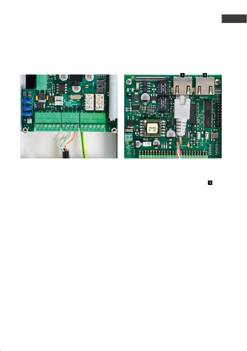
Power supply via PoE according to
IEEE802.3af. If the remote station is connected by means of a screw terminal, the device
supplying power must support phantom
power (supply via wires 1, 2 and 3, 6, e.g. the
Behnke PoE injector).
The 2nd Ethernet port is connected via an
additional RJ45 socket labelled “Port2” .
As the SIP remote station features a PoEfeeding switch, it is possible to connect a PoEcompatible terminal device with a maximum
power drain of 7W to this port.
Please note: There are no screw terminals for
the 2nd Ethernet port.
41www.behnke-online .com
Page 42
Instructions for Behnke SIP 2.0
GB
Hardware
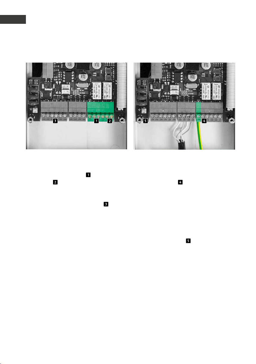
Potential-free outs (relays), ins Grounding connection
The SIP remote station can hold up to two
potential-free outs (Relay 1 , closing contact, relay 2 , changeover contact) via screw
terminals. Additionally, the SIP remote station
provides an electrically isolated input, which
is connected using screw terminals .
The relays load maximum is 2A at 30VDC or
0.5A at 40VAC.
The alarm input triggers upon applying an
input voltage between 10 and 15V=, the
maximum input voltage is 15V=. Please bear
in mind the polarity!
Important: In case the electrical circuit is type
TNV-1, an EARTH must be connected to the
GND screw terminal . A type TNV-1 electrical
circuit is usually used for installations in a
pillar, where the Ethernet cable is installed
outside the building. In case the Ethernet
cable remains within the building, the SIP
remote station does not require a grounding
connection.
The grounding terminal must not be used
here.
42 w ww.behnke-online.com
Page 43
Instructions for Behnke SIP 2.0
Hardware
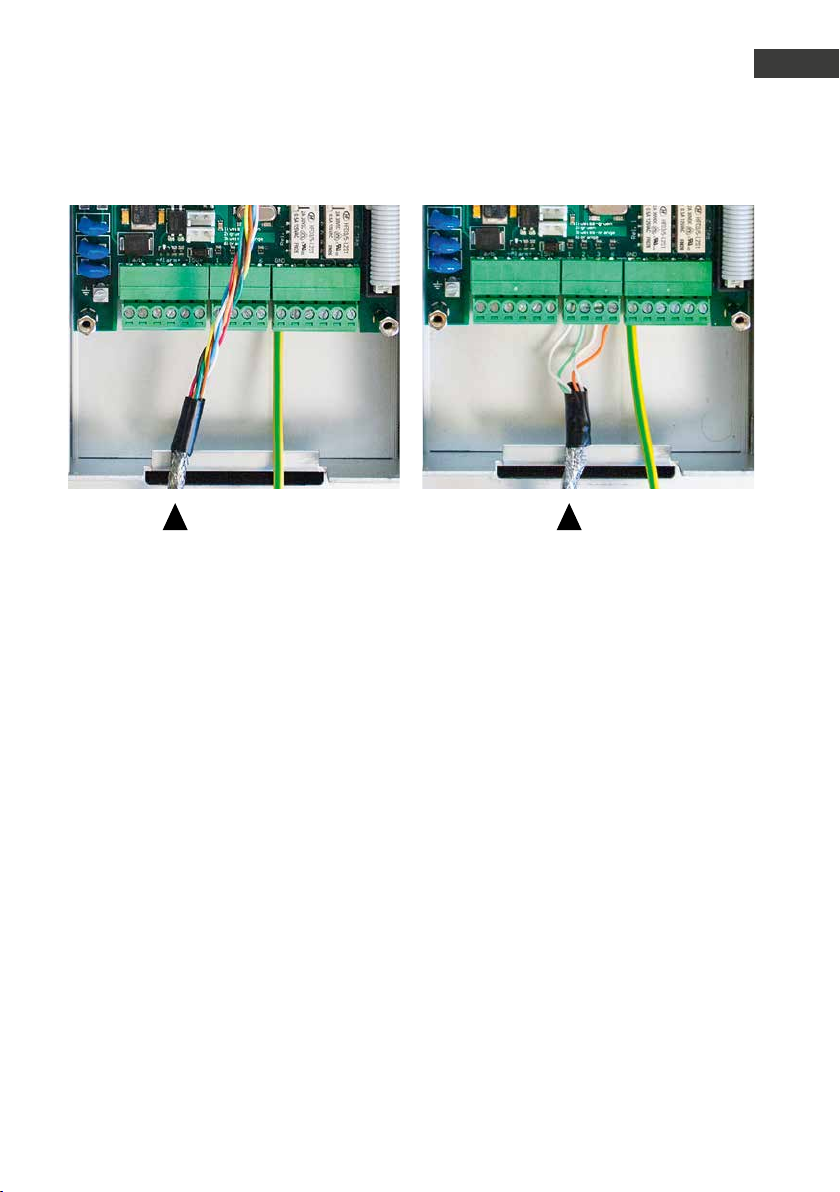
Shielding
Put the earthed Ethernet cable shielding on the lower housing bar as shown in the picture.
GB
43www.behnke-online.com
Page 44

Instructions for Behnke SIP 2.0
GB
Configurations and set-up
3.
configurations and set-up
Preparation
Connect the SIP remote station to the
▸
10/100 Mbit Ethernet network
Power supply via Power over Ethernet
▸
(PoE according to IEEE 802.3af )
Behnke SIP remote stations come pre-set for
an automatic IP configuration via DHCP. It will
automatically obtain its IP address from the
DHCP server, where available. Use the buttons
T1 and T2 on the basic electronics to change
this setting:
After enabling the power supply, it will take
approx. 90 seconds before the device will
produce a dark confirmation signal. Once you
have heard this signal, your remote station is
available.
Please note: When you connect your SIP
remote station to a new network, it may take
up to 3 minutes before the device obtains a
new IP address from the DHCP server.
Use the speaking menu to learn your remote
stationʼs IP address:
1. Press button T1 twice to hear the device say
“Language English”
2. Press button T2 to hear the device say
“State IP-address”
3. Press button T2 to make the device read its
IP address to you
When there is no DHCP server, the remote
stationʼs IP address can be set to “static”:
1. Press button T1 twice to hear the device say
“Language English”
2. Press button T2 to hear the device say
“State IP-address”
3. Press button T1 to hear the device say
“Select IP-address setting”
4. Press button T2 to hear the device say
“dynamic”
5. Press button T1 to hear the device say
“static”
6. Press button T2 to confirm the selection
Now, the SIP remote station is set to a static IP
address; its IP address is 192.168.100.100, and
the subnet mask is 255.255.255.0.
To continue the configuration process,
please use the web front end, which uses
SSL encryption (https). The manufacturer
included a signed SSL certificate, which leads
to a security prompt in common browsers.
By clicking “Continue to this website (not
recommended)”, you will still get access to
the configuration page. To bypass this query
in the future, it is possible to locally save
the certificate in the browser. How to do so
depends on the type of browser you use,
so that we are unable to provide a standard
procedure.
44 ww w.behnke-online.com
Page 45
Instructions for Behnke SIP 2.0
Configurations and set-up
GB
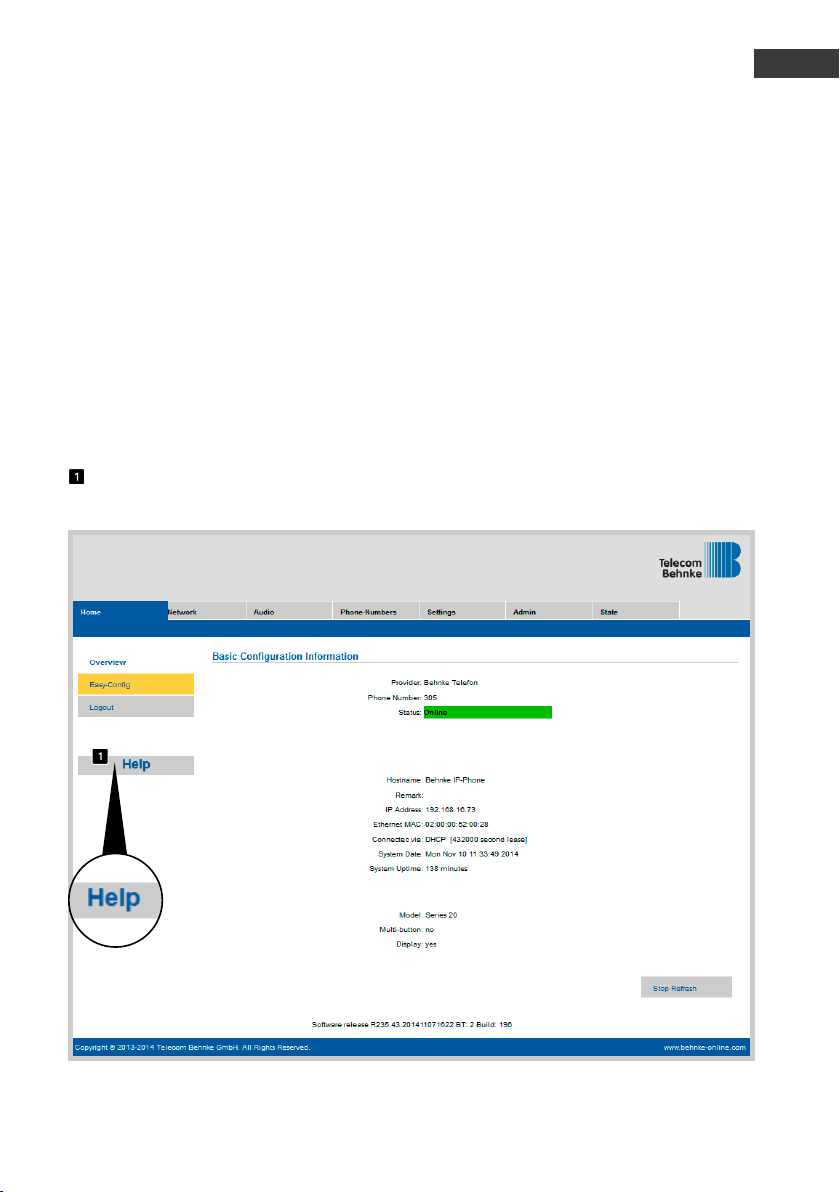
Once you get to the welcome screen, click
login to get to the login page. Standard settings are as follows:
User name: admin
•
Password: admin
•
Now you will see the status page for your
Behnke SIP remote station. You may access
the online help by clicking the “Help”-button
in the left column at any time.
Note: During a connected call, you may set
the volume by pressing the keypad buttons on
your phone as follows:
##1 + volume from 1-9
▸
##2 + microphone sensitivity from 1-9
▸
Example:
Set volume to 5:
▸
##15
Set microphone sensitivit y to 7:
▸
##27
45www.behnke-online.com
Page 46
Instructions for Behnke SIP 2.0
GB
Auto-Provisioning
4.
auto-provisioning
It is possible to automatically configure your
Behnke SIP remote station using auto-provisioning. Auto-provisioning will affect all the
parameters accessible via the web frontend,
including the phone books. Your Behnke SIP
remote station supports two types of autoprovisioning:
1. Fully automatic by means of DHCP Option
66. To do so, configure the option 66 in the
DHCP server, where you can find the configuration file.
Your Behnke SIP remote station supports
downloads from http, https and ftp servers.
Example of a valid option 66:
ftp://192.168.30.2/behnke/ This folder must
contain a file named as follows:
<MAC address>.txt
where <MAC Address> is the hexadecimal
noted MAC address; as displayed in the web
frontend under “Status” but without the
colons.
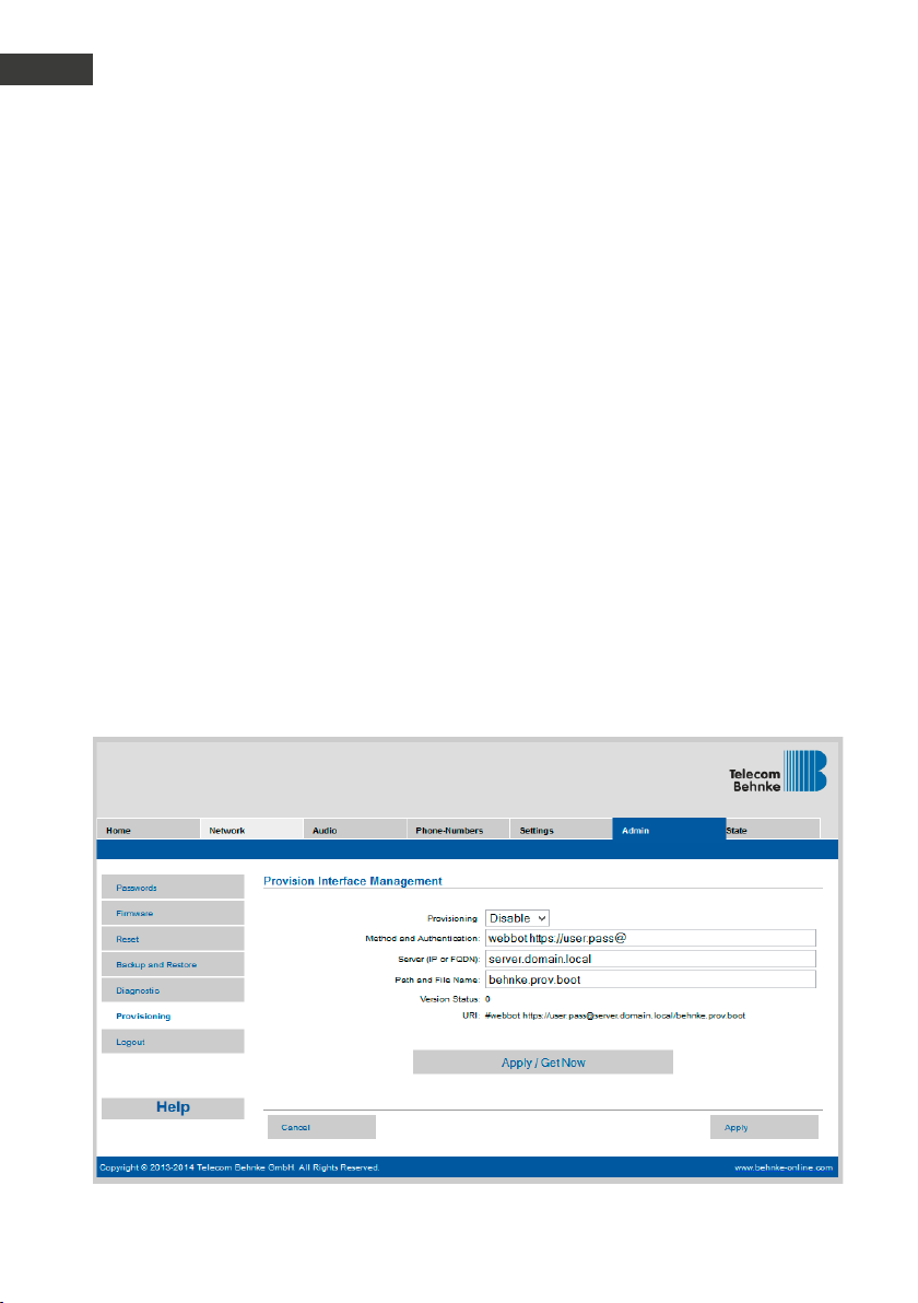
2. Semi-automatic by means of settings made
to the configuration server
Go to “Auto-provisioning” in the web-frontend
to choose the configuration file you want the
remote station to download and the fileʼs
configuration server location.
46 ww w.behnke-online.com
Page 47
5.
reset to default settings
Instructions for Behnke SIP 2.0
Reset to default settings
GB
Complete the following steps to reset the
remote station to its default setting:
Disconnect the power supply to your SIP
▸
remote station
Press buttons T1 and T2 simultaneously and
▸
keep them pressed
Reconnect the power supply to your SIP
▸
remote station
Keep buttons T1 and T2 pressed until two
▸
LEDs (green, blue) start flashing every
second
Release buttons T1 and T2
▸
The remote station will be reset to default
▸
settings; this process takes approx. 90
seconds
Successful completion of the reset will
be confirmed by the speakers emitting a
confirmation tone.
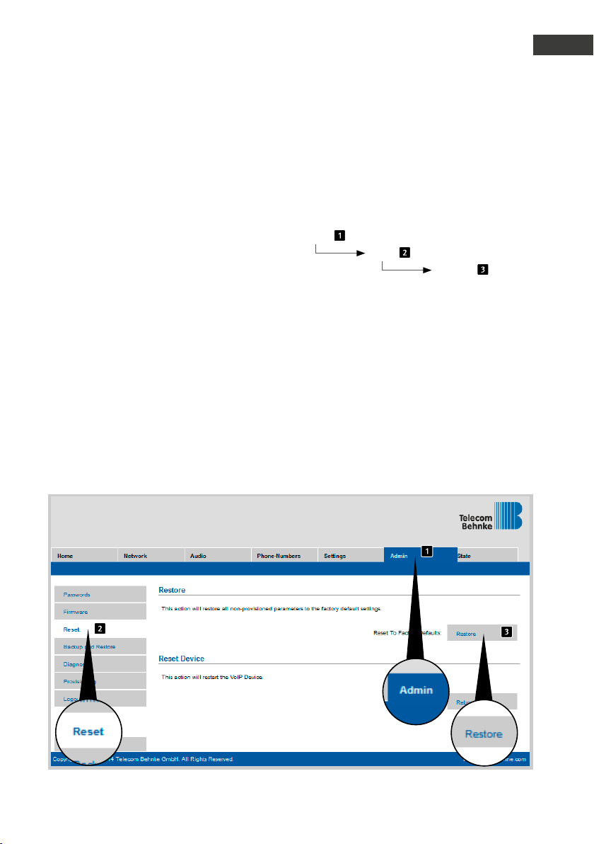
The web interface offers a second option to
reset the device to its default settings, to do
so, please take the following steps:
Admin
Reset
Restore
47www.behnke-online .com
Page 48

Instructions for Behnke SIP 2.0
GB
Technical Specifications
6.
technical specifications
All remote stations
Status/ remote control messages for
▸
integration with third party software
Record up to 9 voice messages each up to 40
▸
seconds long
16 MB joint flash memory for phone book and
▸
voice messages
Store your configuration settings in a file
▸
Network
MAC address (IEEE 802.3)
▸
IPv4 – Internet Protocol version 4 (RFC 791)
▸
ARP – Address Resolution Protocol
▸
DNS – A record (RFC 1706)
▸
DHCP Client – Dynamic Host Configuration
▸
Protocol (RFC 2131)
TCP – Transmission Control Protocol (RFC 93)
▸
UDP – User Datagram Protocol (RFC 768)
▸
RTP – Real Time Protocol (RFC 1889) (RFC
▸
1890)
RTCP – Real Time Control Protocol (RFC 1889)
▸
DiffServ (RFC 2475), Type of Service (RFC 791,
▸
RFC 1349)
SNTP – Simple Network Time Protocol
▸
(RFC 2030)
SIPv2 – Session Initiation Protocol Version 2
▸
(RFC 3261, 3262,3263, 3264)
SIP in NAT networks (STUN)
▸
Auto-provisioning via DHCP option 66 or via
▸
configured server
Backup SIP server configurable
▸
Firmware update via web interface
▸
Integrated PoE switch supporting tagged
▸
VLANs
Voice codecs
G.711 (A-law, μ-law)
▸
G726 (32 kbps)
▸
G.721
▸
In-Band, Out-of-Band DTMF and SIP-Info
▸
(RFC 2833)
Full duplex, echo suppression (AEC)
▸
10 possible speaker volume settings
▸
10 possible microphone sensitivity settings
▸
Series 10 IP
Compact device with integrated speakers
▸
and microphone
One or two call buttons with illuminated
▸
labels
One relay to configure freely
▸
Series 20 IP
Modular design
▸
Up to 8 direct call buttons to which phone
▸
numbers may be assigned freely
Two relays to configure freely
▸
Optional safety relay for remote installation
▸
Keypad module available, functions:
▸
Directly dial phone numbers
•
Code lock
•
Speed dialling with up to 100 phone
•
numbers
Display module available, functions
▸
Illuminated
•
Four lines with up to 20 characters each
•
Info texts depending on the device status,
•
configurable
199 phone book entries, more entries upon
•
request
Multifunctional button holding 100 call
▸
buttons upon request
48 www.behnke-online.com
Page 49

Instructions for Behnke SIP 2.0
Technical Specifications
GB
Safety and administration
Password protection for admin access
▸
Web browser assisted administration
▸
Physical connections
RJ45 port for Ethernet 100baseT, alterna-
▸
tively by means of a screw terminal
Screw terminals for establishing the relay
▸
contacts
Electrical characteristics
Power over Ethernet power supply (PoE
▸
according to IEEE 802.3af)
Max. power drain: 12 W
▸
SIP remote station: 5 W
▸
Device at PORT2: max. 7W
▸
Max. relay load:
▸
2A/30VDC
0.5A/40VAC
Input voltage, alarm input:
▸
10V up to max. 15V
Operating temperature range: -20°C to
▸
+50°C
TNV-1: In TNV-1 circuits, the SIP remote
▸
station must be grounded using the GND
connection, cf. chapter 2.3. Connections,
grounding connection
EMC: EN55022 A / B, EN55024
▸
Safety: EN60950
▸
49www.behnke-online.com
Page 50
Instructions for Behnke SIP 2.0
GB
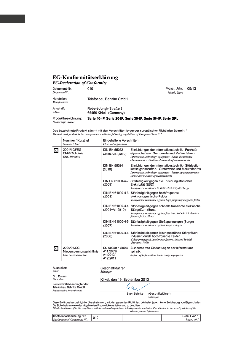
CE Declaration
7.
ce declaration
50 ww w.behnke-online.com
Page 51

8.
legal information
Instructions for Behnke SIP 2.0
Legal Information
GB
1. We reser ve the right to change our products, without notice, for technical progress.
As a result of continuous development, the
products illustrated may look different from
the products actually delivered.
2. Reprints of texts, images or pictures or
copies from these instructions in any media
– given in full or as extracts – require our
express written consent.
3. Design and layout of these instructions are
copyright protected. We do not assume any
liability for possible errors, contents errors
and misprints (including technical data or
within images and technical diagrams).
Information with regard to product liability:
1. All products mentioned in these inst-
ructions may only be used for the purpose
intended. In case of doubts, please contact a
competent specialist or our services department (cf. telephone numbers).
2. Products with a power supply (especially
those plugged in to 230V) must be unplugged
before opening or during installation.
3. Damage and consequential damage resul-
ting from altering or meddling with our products or their improper use are excluded from
product liability. This also applies to improper
storage or external influences.
4. The respective guidelines for working on
power supplies with 230V or batteries equally
apply to working with our products, e.g. directives regarding electromagnetic compatibility
or the Low Voltage Directive. Please leave
corresponding work to trained specialists
familiar with the matter.
Electromagnetic
Compatibility
Low Voltage Directive
5. Our products meet all technical guidelines
and telecommunications regulations currently
applicable in Germany and the EU.
51www.behnke-online .com
Page 52

Instructions for Behnke SIP 2.0
GB
Notes
52 w ww.behnke- online.com
Page 53

D SIP-Sprechstellen Seite .........3
GB SIP intercoms Page ........ 29
F Postes téléphoniques SIP Page ....... 55
notice
Version 2.3
Page 54

Manuel dʼutilisation Behnke SIP 2.0
F
Contact
Remarques importantes
Veuillez vous assurer que les dispositifs
et accessoires Behnke ne sont installés et
entretenus que par des électriciens agréés
respectant les consignes de sécurité.
contact
Infoligne
Pour des informations détaillées
concernant nos produits, projets et
services:
Tél.: +33 (0)3 87 84 99 50
Hotline SAV 24h/24h
Vous avez besoin dʼaide? Nous sommes
à votre service 24h/24 et vous proposons
des conseils et solutions pour toutes vos
questions dʼordre technique, ainsi quʼune
aide à la mise en service:
Tél.: +33 (0)3 87 84 99 55
Avant d’effectuer des travaux d’entretien ou de
réparation, toujours débrancher les appareils
des réseaux électrique (bloc d’alimentation) et
informatique ou ligne téléphonique.
Vous trouverez des informations légales complémentaires sur la page 77.
Telecom Behnke S.àr.l.
1, Avenue Saint Rémy
F-57600 Forbach
France
Email et adresse internet
[email protected]
www.behnke-online.fr
54 www.behnke-online.fr
Page 55

Manuel dʼutilisation Behnke SIP 2.0
Sommaire
sommaire
1. Introduction 56
1.1. Étendue de la livraison .................................................................................................. 56
1.2. Généralités ................................................................................................................... 56
1.3. Montage des postes téléphoniques des séries 20 et 30 ................................................ 58
1.4. Placer lʼétiquette .......................................................................................................... 62
2. Composants 64
2.1. Électronique de base, série 20, 30, 50 ........................................................................... 64
2.2. Appareils compacts, série 10 ........................................................................................ 65
2.3. Raccordements ............................................................................................................. 66
3. Configuration et mise en service 70
4. Configuration automatique 72
5. Réinitialisation aux paramètres dʼusine 73
F
6. Caractéristiques techniques 74
7. Déclaration CE 76
8. Informations légales 77
55www.behnke-online.fr
Page 56

Manuel dʼutilisation Behnke SIP 2.0
F
Introduction
1.
introduction
1.1. Étendue de la livraison
Électronique de base sous forme de
▸
boîtier électronique des séries 20, 30, 50
•
ou
poste téléphonique compact de la série 10
•
Ce manuel
▸
1.2. Généralités
Caractéristiques
Les postes téléphoniques SIP de Behnke
des séries 20, 30, 40 et 50 sont des postes
téléphoniques VoIP modulaires intégrant
une suppression de lʼécho acoustique pour
une conversation mains libres en duplex,
dʼexcellente qualité. Les modules tels que
haut-parleur, microphone, clavier numérique
et touches dʼappel ainsi que lʼélectronique,
sont logés dans un boîtier à double paroi sous
forme dʼunité compacte. Lʼinterchangeabilité
des modules permet une flexibilité exceptionnelle lors de la planification et de
lʼinstallation. La communication sʼeffectue
par Voice over IP (VoIP) selon le standard SIP
via le branchement Ethernet LAN, soit à lʼaide
dʼune installation téléphonique compatible
SIP, dʼun fournisseur SIP ou par sélection
directe dʼune adresse IP. La configuration
ainsi que les mises à jour logicielles se font
à partir dʼun navigateur web. Lʼalimentation
du produit passe par le câble LAN (PoE). Les
postes téléphoniques permettent le raccordement de touches dʼappel direct externes et
possèdent des sorties de commutation à configuration libre pour lʼouverture des portes,
lʼafficheur dʼappel ou dʼautres fonctions de
commutation. Des modules supplémentaires
permettent dʼajouter dʼautres fonctions,
comme par exemple un écran LCD à 4 lignes
avec répertoire téléphonique ou jusquʼà 100
touches dʼappel direct.
56 www.behnke-online.fr
Page 57

Manuel dʼutilisation Behnke SIP 2.0
Introduction
F
Les postes téléphoniques compacts prémontés des séries 10 sont de grande qualité et disposent de deux touches dʼappel au maximum.
Ils sont également équipés dʼun système de
suppression de lʼécho acoustique et permettent ainsi une conversation mains libres en
duplex, dans des conditions optimales. Ces
postes téléphoniques sont équipés dʼun relais
pouvant être configuré librement.
Configuration système requise
Les conditions minimales suivantes sont
nécessaires pour lʼinstallation du poste téléphonique SIP de Behnke:
PC ou Apple Macintosh avec navigateur Web
▸
(par ex. Microsoft Internet Explorer, Mozilla
Firefox, Apple Safari)
Moniteur / carte graphique avec une résolu-
▸
tion min. de 1024 x 768 pixels / 32 bit
Carte réseau configurée
▸
Un port réseau Ethernet libre avec PoE ou
▸
injecteur PoE séparé
Compte SIP, serveur SIP ou station éloignée
▸
acceptant les connexions SIP directes
Pour lʼinstallation du logiciel IP Vidéo de
Behnke, la configuration minimale suivante
est requise:
PC avec processeur Intel® Pentium® IV
▸
(1,7GHz) ou processeur AMD Athlon™
(1,2GHz) ou supérieur
Carte réseau configurée
▸
Système dʼexploitation Microsoft Windows
▸
2000® ou Windows XP ou ultérieur
128 MB de RAM ou supérieur
▸
Moniteur / carte graphique avec résolution
▸
minimum 1024 x 768 pixels et représentation TrueColor
57www.behnke-online.fr
Page 58

Manuel dʼutilisation Behnke SIP 2.0
F
Introduction
1.3. Montage des postes téléphoniques
des séries 20 et 30
Remarque : pour des raisons dʼoptique et de
protection contre lʼhumidité veillez au sens
du brossage de lʼaluminium lors de la mise en
place des modules!
En cas de montage délocalisé courte distance
de lʼélectronique, le boîtier de lʼélectronique
est remplacé par une contre-plaque ouverte
correspondant au cadre avant.
Relier les câbles dans lʼordre suivant :
1. Touches (RT) ▸ aux connecteurs MQS de 1 à
8 marqués par la bague jaune
2. Haut-parleur (HP) ▸ au connecteur marqué
par la bague bleue
3. Microphone (Mic) ▸ au connecteur marqué
par la bague blanche
4. Clavier numér ique ▸ au connecteur blanc à
12 broches
Attention: ne pas intervertir les connecteurs
du haut-parleur et du microphone!
Poser les câbles non utilisés dans le boîtier des modules avec lʼextrémité ouverte
(connecteur) vers le bas. Cela empêche
lʼinfiltration de lʼhumidité dans le connecteur.
Poser ensuite le boîtier de lʼélectronique sur
le boîtier des modules.
58 www.behnke-online.fr
Page 59
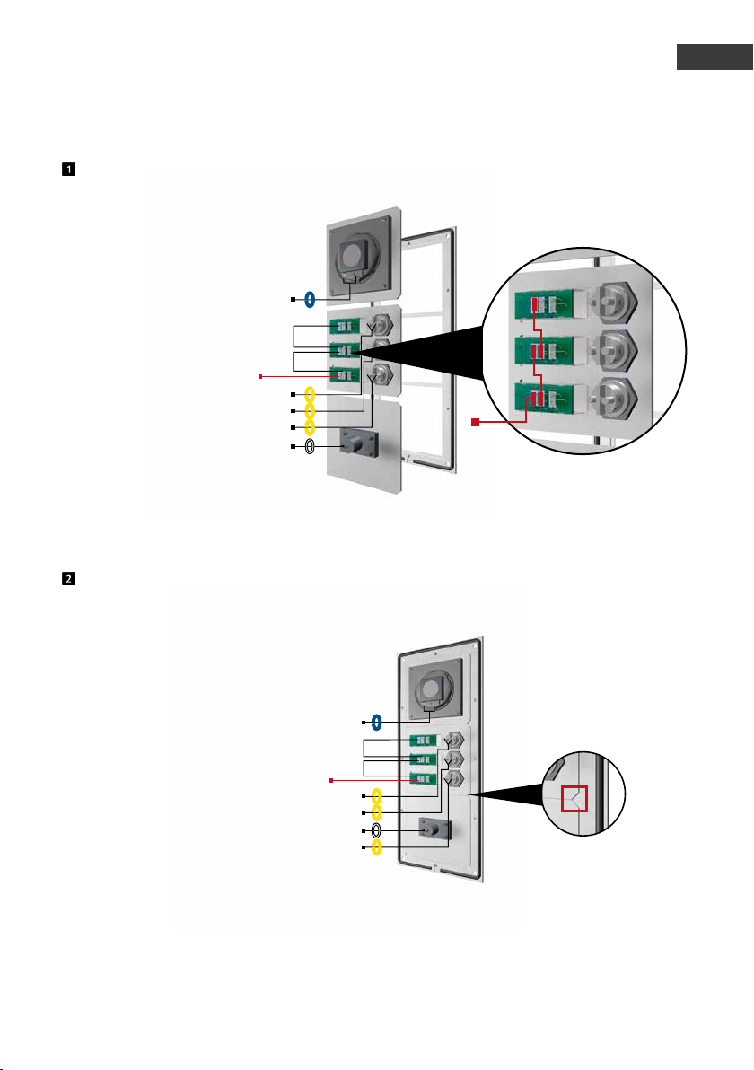
Insérer les modules fonctionnels dans le cadre avant
HP
Ponts
Éclairage 12 V=
RT
T
RT
T
RT
T
Mic
Encastrer les modules par lʼarrière dans le cadre.
Manuel dʼutilisation Behnke SIP 2.0
Introduction
Éclairage
12 V=
Ponts 12 V pour lʼéclairage
des champs dʼinscription
F
Modules fonctionnels dans le cadre avant
HP
Éclairage 12 V=
RT
T
RT
T
Mic
RT
T
Lors de lʼinsertion des modules, veiller impérativement au positionnement. Les modules doivent émettre un « clic » audible lorsquʼils sont insérés.
59www.behnke-online.fr
Page 60
Manuel dʼutilisation Behnke SIP 2.0
F
Introduction
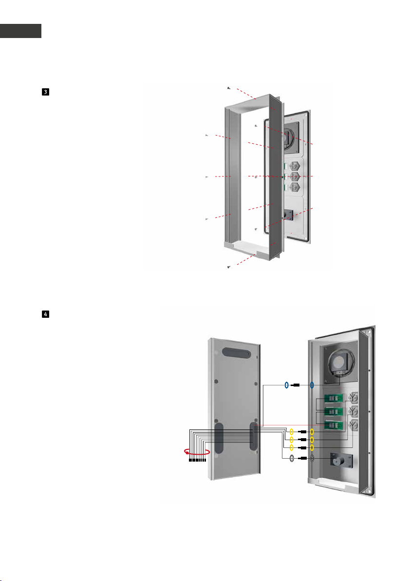
Fixation du boîtier des modules
Fixer le boîtier des modules
sur le cadre avant.
Boîtier électronique Boîtier modulaire
Affectation des connecteurs, câblage
Série 20, 30, 50 :
HP (bleu) ▸ haut-parleur
Mic (blanc) ▸ microphone
T1 à T8 (jaune) ▸ touches 1 à 8
Eclair age 12 V=
T1
T2
T3
T
T
T
Connecteur à 12 broches ▸ clavier
Connecter les différents composants
avec le câble plat. Attachez les câbles
dont vous nʼavez pas besoin avec un
câble plat (les connecteurs sont à
orienter vers le bas).
60 www.behnke-online.fr
Page 61
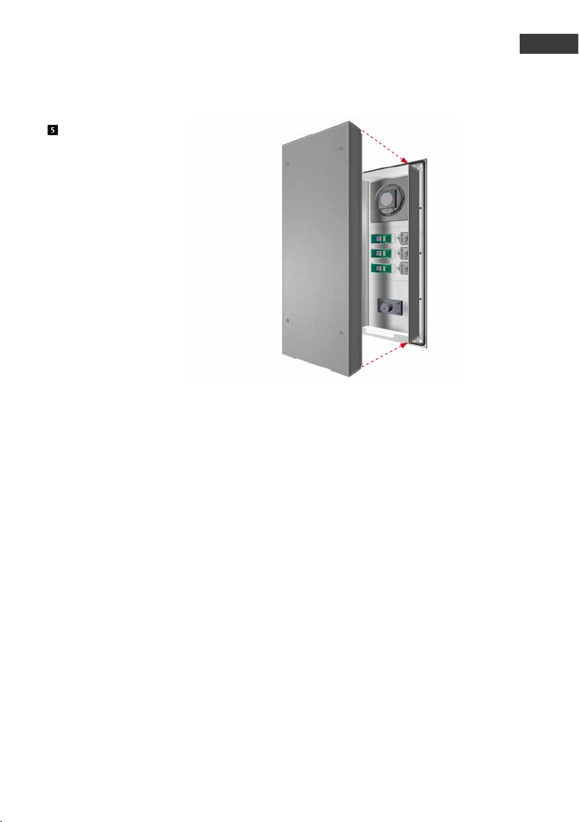
Encliqueter à nouveau le boîtier de
lʼélectronique sur le boîtier des modules.
Manuel dʼutilisation Behnke SIP 2.0
Introduction
F
61www.behnke-online.fr
Page 62
Manuel dʼutilisation Behnke SIP 2.0
F
Introduction
1.4. Placer lʼétiquette
Paramètres dʼusine
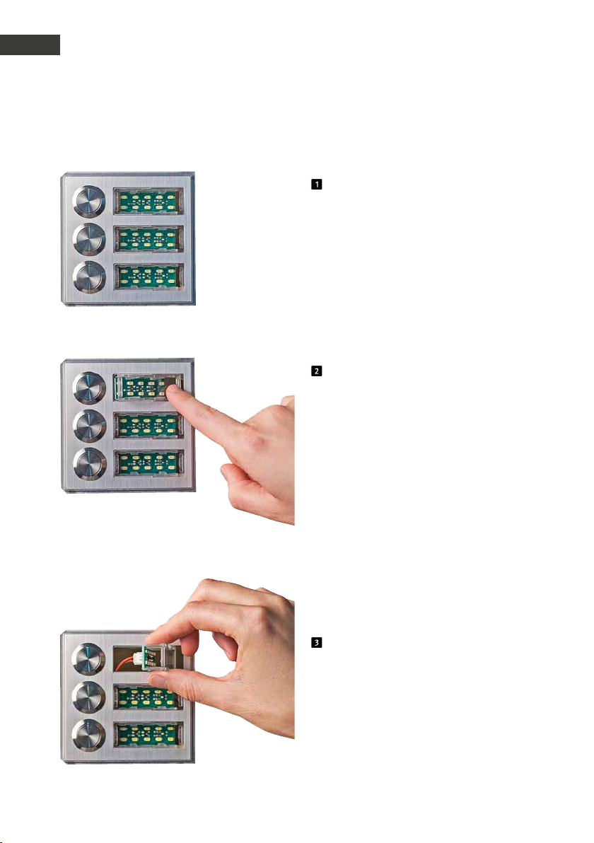
Retirer le champ dʼinscription en appuyant
sur le côté droit
et le faire sortir
62 www.behnke-online.fr
Page 63
Manuel dʼutilisation Behnke SIP 2.0
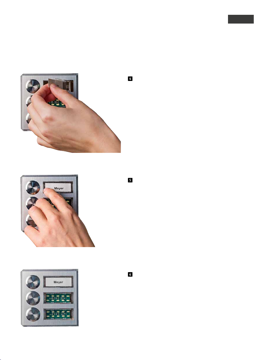
Introduction
Placer lʼétiquette en la glissant de la
gauche vers la droite
Placer lʼextrémité de la vitre du champ
dʼinscription à gauche et lʼemboîter
F
Cʼest tout !
63www.behnke-online.fr
Page 64
Manuel dʼutilisation Behnke SIP 2.0
F
Composants
2.
composants
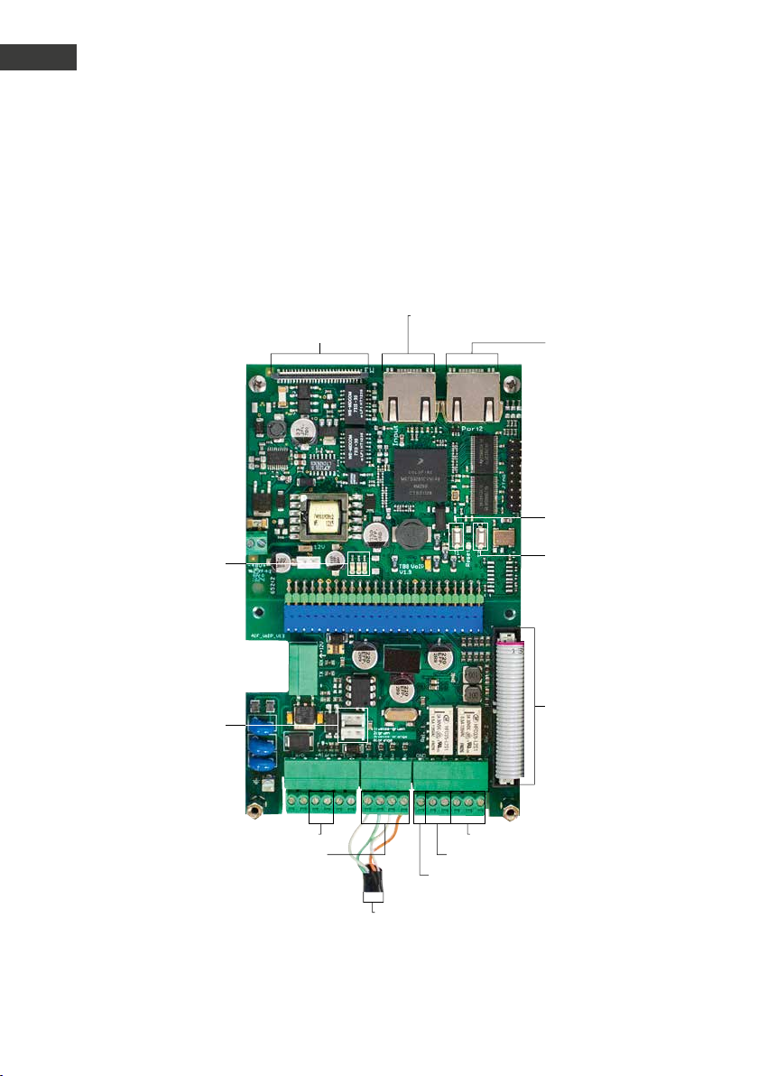
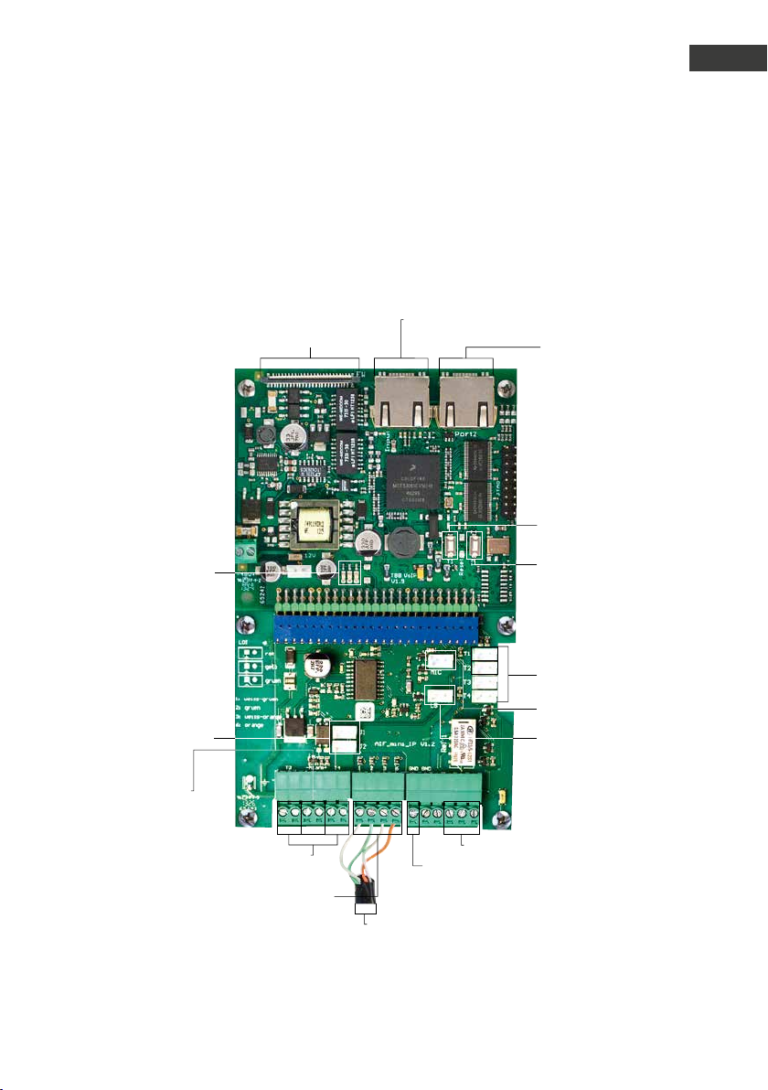
2.1. Électronique de base, série 20, 30, 50
Raccordement dʼextension
DEL:
rouge: alimentation électrique
bleu: en a ttente
vert: enregistré
Raccor dement LAN INPUT
(poste téléphonique SIP)
Raccor dement LAN PORT 2
(Racco rdement pour a utres
appareils IP comme par ex.
camér a IP)
T1
T2
Prise pour
module dʼéclairage
(12 V)
Entrée alarme
Raccordement Ethernet
selon EIA/T IA 568 A
Mise à la te rre
1: bla nc-vert
2: ver t
3: blanc-orange
6: orange
Relais 2, contact inverseur
Relais 1 , contact de tr avail
Câble de raccordement
pour module de fonction
64 www.behnke-online.fr
Page 65
2.2. Appareils compacts, série 10
Raccordement dʼextension
DEL:
rouge: alimentation électrique
bleu: en a ttente
vert: enregistré
Manuel dʼutilisation Behnke SIP 2.0
Raccor dement LAN INPUT
(poste téléphonique SIP)
Composants
Raccor dement LAN PORT 2
(Racco rdement pour a utres
appareils IP comme par ex.
camér a IP)
T1
T2
F
Prise pour
module dʼéclairage
(12 V)
Entrée alarme
Raccordement alternatif
des touc hes dʼappel 3 + 4
Raccordement Ethernet
selon EIA/T IA 568 A
Mise à la te rre
1: bla nc-vert
2: ver t
3: blanc-orange
6: orange
Zone de raccordement
pour touche dʼappel
Microphone
Haut-parleur
Relais 1, contact inverseur
65www.behnke-online.fr
Page 66
Manuel dʼutilisation Behnke SIP 2.0
F
Composants
2.3. Raccordements
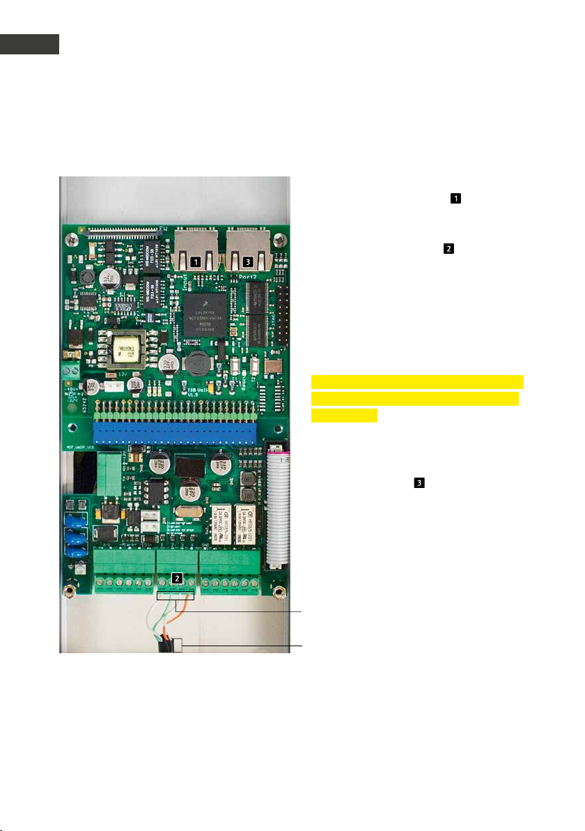
Raccordement LAN - INPUT
Le raccordement LAN se fait généralement au
moyen dʼun connecteur RJ45 ( «INPUT»). En
option, il est également possible de raccorder les fils au moyen dʼune borne à vis sur
lʼinterface de raccordement : le réseau est
connecté sur les bornes marquées avec 1 (vertblanc), 2 (vert), 3 (orange-blanc) et 6 (orange)
selon EIA / TIA 568 A. Le chiffre représente le
pin de la prise RJ45.
Attention:
Veuillez noter que le raccordement ne doit
se faire quʼavec le connecteur RJ45 ou les
bornes à vis !
Pour le raccordement dʼautres appareils
(caméra IP par ex.), utiliser le deuxième connecteur RJ45 (PORT2) .
Raccordement Ethernet selon
EIA/ TIA 568 A
1: bla nc-vert
Raccordement Ethernet selon
EIA/ TIA 568 A
2: ver t
3: blanc-orange
6: orange
66 www.behnke-online.fr
Page 67
Manuel dʼutilisation Behnke SIP 2.0
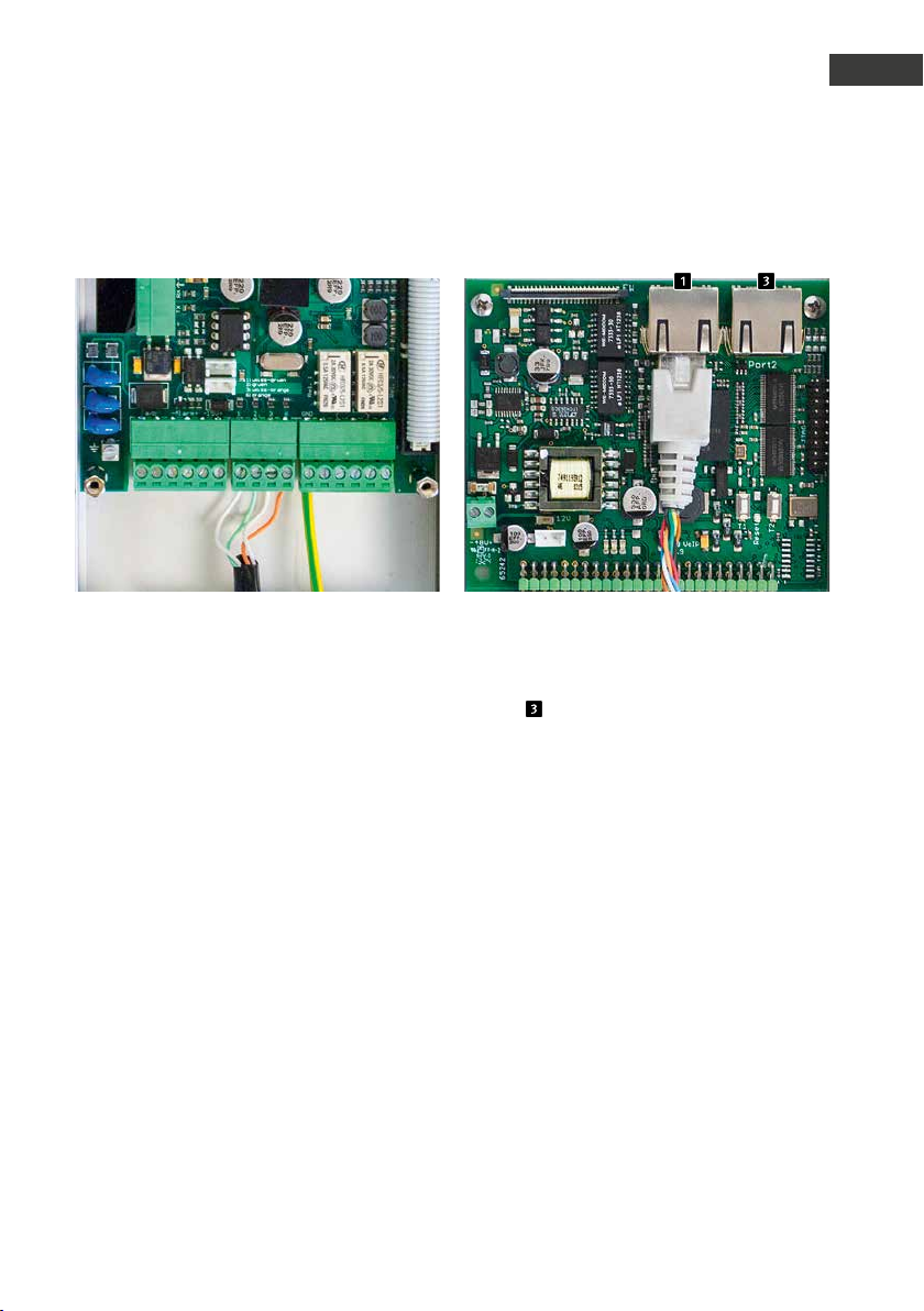
Alimentation électrique Raccord LAN PORT2
Composants
F
Lʼalimentation en énergie sʼeffectue uniquement via PoE selon IEEE802.3af. Si le poste
téléphonique est relié au moyen de bornes à
vis, lʼappareil fournissant le courant doit alors
supporter lʼalimentation fantôme (alimentation en énergie via les fils 1, 2 et 3, 6 p.ex.
lʼinjecteur PoE Behnke).
Le 2ème por t Ethernet est disponible via un
autre connecteur RJ45 portant lʼinscription «
Port2 » .
Étant donné que le poste téléphonique
SIP dispose dʼun switch fournissant une
alimentation PoE, il est possible de raccorder
un appareil compatible PoE avec une
consommation dʼénergie de 7 Watt maximum.
Attention: il nʼy a pas de de borne à vis pour
le 2ème port Ethernet.
67www.behnke-online.fr
Page 68
Manuel dʼutilisation Behnke SIP 2.0
F
Composants
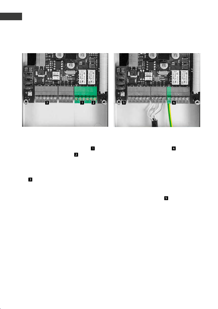
Sorties à potentiel isolé (relais), entrées Mise à la terre
Le poste téléphonique SIP met à disposition
deux sorties à potentiel isolé (relais 1 ,
contact à fermeture, relais 2 , contact inverseur) via des bornes à vis. De plus, le poste
téléphonique SIP met à disposition une entrée
à potentiel isolé, raccordée par des bornes à
vis .
Les relais commutent au maximum 2A à 30VCC
ou 0,5A à 40VCA.
Lʼentrée alarme commute à lʼapplication dʼune
tension comprise entre 10 et 15V=, la tension
dʼentrée maximale est de 15V=. Tenir compte
de la polarité !
Attention: sʼil sʼagit dʼun circuit TNV-1, il faut
raccorder les bornes à vis GND à la terre.
Un circuit TNV-1 est en général une installation
dans une colonne, car le câble de raccordement Ethernet est posé à lʼextérieur du bâtiment. Si le câble Ethernet reste à lʼintérieur du
bâtiment, le poste téléphonique SIP ne doit
pas obligatoirement être relié à la terre.
La borne de mise à la terre ne doit pas être
utilisée dans ce cas.
68 www.behnke-online.fr
Page 69
Manuel dʼutilisation Behnke SIP 2.0
Composants
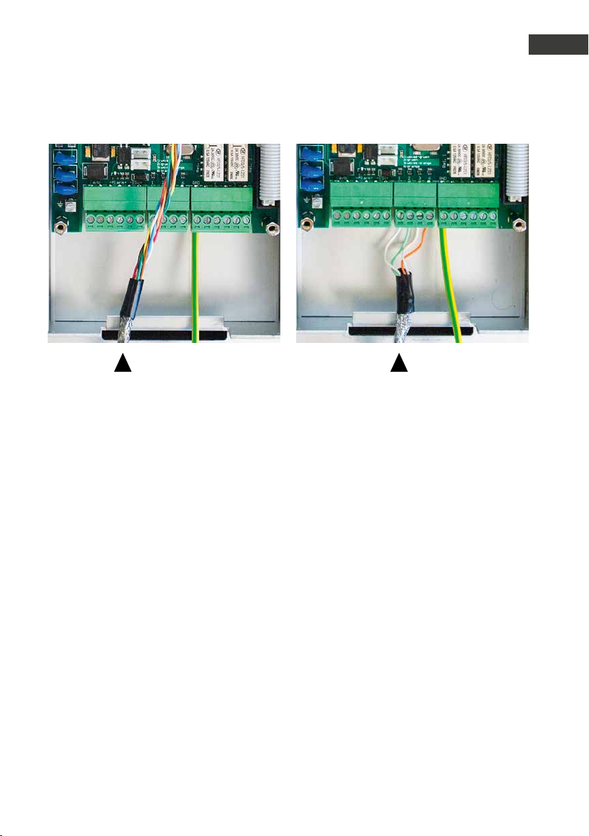
Blindage
Poser le blindage du câble Ethernet mis à la terre sur la barrette en bas du boîtier, tel quʼindiqué
sur la photo
F
69www.behnke-online.fr
Page 70

Manuel dʼutilisation Behnke SIP 2.0
F
Configuration et mise en service
3.
configuration et mise en service
Préparation
Raccordement du poste téléphonique SIP au
▸
réseau Ethernet 10/100 Mbit
Alimentation électrique via Power over
▸
Ethernet (PoE selon IEEE 802.3af )
Le poste téléphonique SIP de Behnke est par
défaut configuré avec IP automatique via
DHCP. Il définit lʼadresse IP automatiquement
en fonction du ser veur DHCP, si disponible.
Avec les touches T1 et T2 de lʼélectronique de
base, ce mode peut être modifié:
Après la connexion de lʼalimentation, il faut
environ 90 secondes avant quʼune tonalité
grave soit émise. Celle-ci signale que le poste
téléphonique est prêt à fonctionner.
Attention: lorsque le poste téléphonique
SIP est connecté à un nouveau réseau, cela
peut prendre jusquʼà 3 minutes avant que le
serveur DHCP ne lui attribue une nouvelle
adresse IP.
Lʼadresse IP du poste téléphonique peut ensu-
ite être transmise via le menu langue:
1. Appuyer sur T1 trois fois, le son «langue
française» retentit
2. Appuyer sur T2, le son «lecture dʼadresse
IP» retentit
3. Appuyer sur T2, lʼadresse IP du poste
téléphonique retentit
Lorsquʼil nʼy a aucun serveur DHCP disponible, lʼattribution dʼune adresse IP se fait de
manière «statique»:
1. Appuyer sur T1 trois fois, le son «langue
française» retentit
2. Appuyer sur T2, le son «lecture dʼadresse
IP» retentit
3. Appuyer sur T1, le son «arrêt dʼattribution
dʼadresse IP» retentit
4. Appuyer sur T2, le son «dynamique»
retentit
5. Appuyer sur T1, le son «statique» retentit
6. Appuyer sur la touche T2 pour valider la
sélection
Le poste téléphonique SIP est donc configuré
avec attribution statique dʼadresse IP avec
lʼadresse IP 192.168.100.10 0 et le masque de
sous-réseau 255.255.255.0.
Reprendre ensuite la configuration à partir de
lʼinterface web, cette dernière est sécurisée
grâce à un encryptage SSL (https). Dans le
poste téléphonique SIP, un certificat SSL à
signature individuelle a été installé par le
fabricant, ce qui peut entraîner lʼaffichage de
fenêtres dʼavertissements avec certains navigateurs. En sélectionnant «continuer le chargement de cette page (non recommandé)»,
il est possible dʼavoir accès à lʼinterface de
configuration. Afin de ne plus devoir répondre
à cette question, le certificat peut aussi être
sauvegardé dans le navigateur. Ce processus
est différent en fonction du navigateur utilisé,
cʼest pourquoi il est impossible dʼen donner
une description générale précise.
70 www.behnke-online.fr
Page 71
Manuel dʼutilisation Behnke SIP 2.0
Configuration et mise en service
F
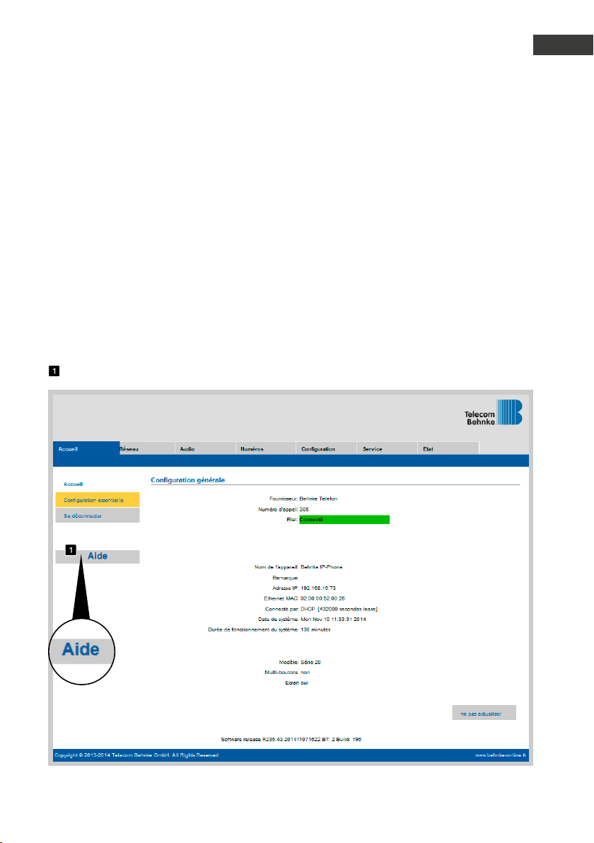
Lorsque lʼécran dʼaccueil apparaît, il est
possible de passer à lʼécran dʼenregistrement
avec demande du mot de passe en cliquant
sur «sʼenregistrer». Les paramètres standard
sont les suivants :
Nom dʼutilisateur : admin
•
Mot de passe : admin
•
Le statut du poste téléphonique SIP de
Behnke sʼaffiche à lʼécran. Lʼaide en ligne est
accessible à tout instant via la touche « Aide »
dans la colonne de gauche.
Remarque : en communication, lʼacoustique
peut être réglée en appuyant sur les touches
du téléphone comme suit :
##1 + volume du haut-parleur de 1 à 9
▸
##2 + sensibilité du microphone de 1 à 9
▸
Exemple :
Régler le volume sur 5 :
▸
##15
Régler la sensibilité du micro sur 7 :
▸
##27
71www.behnke-online.fr
Page 72
Manuel dʼutilisation Behnke SIP 2.0
F
Configuration automatique
4.
configuration automatique
Grâce à cette fonction, le poste téléphonique
SIP de Behnke se laisse configurer de manière
automatique. Tous les paramètres accessibles
via lʼapplication Web, y compris les répertoires téléphoniques, peuvent être installés
avec la configuration automatique. Le poste
téléphonique SIP de Behnke est compatible
avec deux types de configurations automatiques :
1. Entièrement automatique avec DHCP Option
66. Pour ce faire, lʼoption 66 est conf igurée
dans le serveur DHCP, là où se trouve le fichier
de configuration.
Le poste téléphonique SIP de Behnke est
compatible avec le téléchargement de http,
https ou de serveurs ftp.
Exemple pour une option 66 valide :
ftp://192.168.30.2/behnke/
Un fichier avec le nom suivant doit être
déposé dans ce dossier:
<MAC-Adresse>.txt
ici <MAC-Adresse> est lʼadresse MAC hexadécimale, telle quʼelle est aussi affichée dans
lʼapplication Web sous « état », cependant
sans « : ».
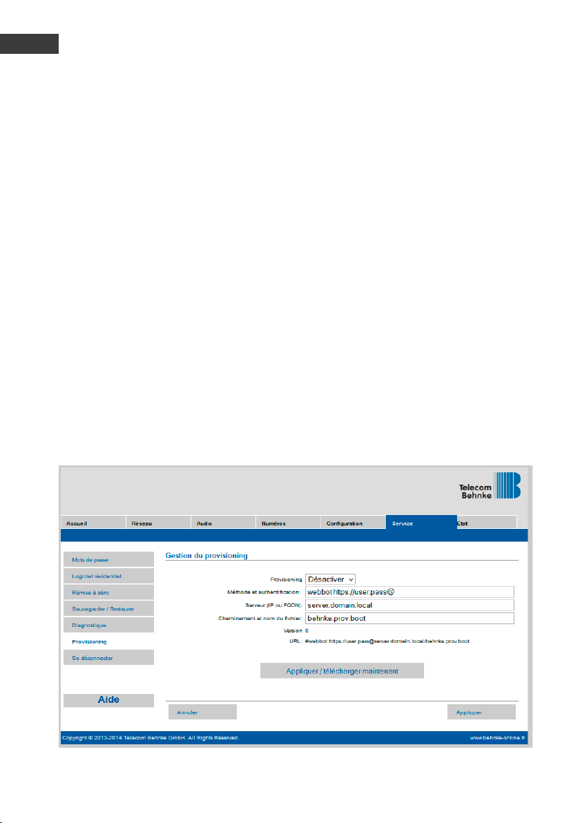
2. Semi-automatique en indiquant
un serveur de configuration
Ici, il est possible de définir dans lʼapplication
Web sous « provisioning » le fichier de configuration qui sera téléchargé par le poste
téléphonique et le serveur de configuration
utilisé.
72 www.behnke-online.fr
Page 73
Manuel dʼutilisation Behnke SIP 2.0
Réinitialisation aux paramètres dʼusine
5.
réinitialisation aux paramètres dʼusine
F
Pour effectuer une réinitialisation aux paramétrages dʼusine, suivre la procédure :
Mettre le poste téléphonique SIP hors
▸
tension
Appuyer et maintenir les touches T1 et T2
▸
simultanément.
Remettre le poste téléphonique SIP sous
▸
tension
Maintenir les touches T1 et T2 appuyées
▸
jusquʼà ce que les deux DEL (verte, bleue)
clignotent par intermittence dʼune seconde.
Relâcher les touches T1 et T2
▸
La réinitialisation aux paramètres dʼusine
▸
est en cours, durée env. 90s
La réinitialisation a été effectuée avec succès
lorsquʼune tonalité de confirmation est émise
par le haut-parleur.
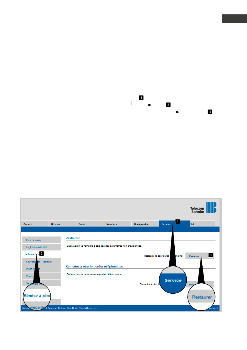
Lʼinterface Web offre une autre possibilité
pour réinitialiser lʼappareil aux paramètres
dʼusine. La procédure est la suivante :
Admin
Reset
Réinitialiser
73www.behnke-online.fr
Page 74

Manuel dʼutilisation Behnke SIP 2.0
F
Caractéristiques techniques
6.
caractéristiques techniques
Tous les postes téléphoniques
Messages dʼétat et de télécommande pour
▸
intégration dans un logiciel tiers
9 messages vocaux enregistrables avec une
▸
durée respective de 40s
16 Mo de mémoire flash pour répertoire
▸
téléphonique et annonces vocales
Configuration enregistrable dans un fichier
▸
Réseau
Adresse MAC (IEEE 802.3)
▸
IPv4 – Internet Protocol Version 4 (RFC 791)
▸
ARP – Address Resolution Protocol
▸
DNS – A record (RFC 1706)
▸
DHCP Client – Dynamic Host Configuration
▸
Protocol (RFC 2131)
TCP – Transmission Control Protocol (RFC 93)
▸
UDP – User Datagram Protocol (RFC 768)
▸
RTP – Real Time Protocol (RFC 1889) (RFC
▸
1890)
RTCP – Real Time Control Protocol (RFC 1889)
▸
DiffServ (RFC 2475), Type of Service (RFC 791,
▸
RFC 1349)
SNTP – Simple Network Time Protocol
▸
(RFC 2030)
SIPv2 – Session Initiation Protocol Version 2
▸
(RFC 3261, 3262,3263, 3264)
SIP dans réseaux NAT (STUN)
▸
Auto-approvisionnement via DHCP Option 66
▸
ou par ser veur de configuration
Backup-SIP-Ser ver configurable
▸
Mise à jour du Firmware via interface Web
▸
POE-Switch intégré compatible Tagged
▸
VLANs
Codecs vocaux
G.711 (A-law, μ-law)
▸
G726 (32 kbps)
▸
G.721
▸
DTMF In-Band, Out-of-Band et SIP-Info
▸
(RFC 2833)
Duplex, suppression de lʼécho (AEC)
▸
Volume haut-parleur réglable sur 10 niveaux
▸
Sensibilité du microphone réglable sur 10
▸
niveaux
Série 10 IP
Appareil compact avec haut-parleur intégré
▸
et microphone
Une ou deux touches dʼappel avec champs
▸
dʼinscription éclairés
Un relais à configuration libre
▸
74 www.behnke-online.fr
Page 75

Manuel dʼutilisation Behnke SIP 2.0
Caractéristiques techniques
F
Série 20 IP
Conception modulaire
▸
Jusquʼà 8 touches dʼappel direct à
▸
configuration libre du numéro
Deux relais à configuration libre
▸
En option, relais de sécurité disponible pour
▸
montage délocalisé
Module clavier numérique disponible avec
▸
fonctions :
Sélection directe des numéros dʼappel
•
Ouverture à code
•
Numérotation rapide jusquʼà 100
•
destinations
Écran dʼaffichage disponible avec fonctions :
▸
Rétroéclairé
•
Quatre lignes de 20 caractères chacune
•
Messages dʼinformation, indiquant lʼétat
•
de lʼappareil, configurables
199 entrées dans le répertoire
•
téléphonique, plus sur demande
Jusquʼà 100 touches dʼappel, sur demande
▸
Sécurité et administration
Protection du mode dʼadministration par
▸
mot de passe
Administration par navigateur Web
▸
Raccordements physiques
RJ45-Port pour Ethernet 100baseT ou en
▸
alternative sur borne à vis
Relais accessible sur Bornes à vis
▸
Caractéristiques électriques
Alimentation électrique via Power over
▸
Ethernet (PoE selon IEEE 802.3af )
Puissance absorbée max. : 12 W
▸
Combiné SIP : 5 W
▸
Appareil sur PORT2 : 7 W max.
▸
Puissance de commutation max. des relais :
▸
2 A/30VDC
0.5 A/40VAC
Tension dʼentrée alarme :
▸
10V à 15V max.
Température de service : -20° C à +50° C
▸
TNV-1 : pour les circuits TNV-1, le poste
▸
téléphonique SIP doit être relié à la terre
via le raccord de masse, voir chapitre 2.3.
Raccordements, raccordement à la terre
CEM : EN55022 A /B, EN55024
▸
Safety : EN60950
▸
75www.behnke-online.fr
Page 76
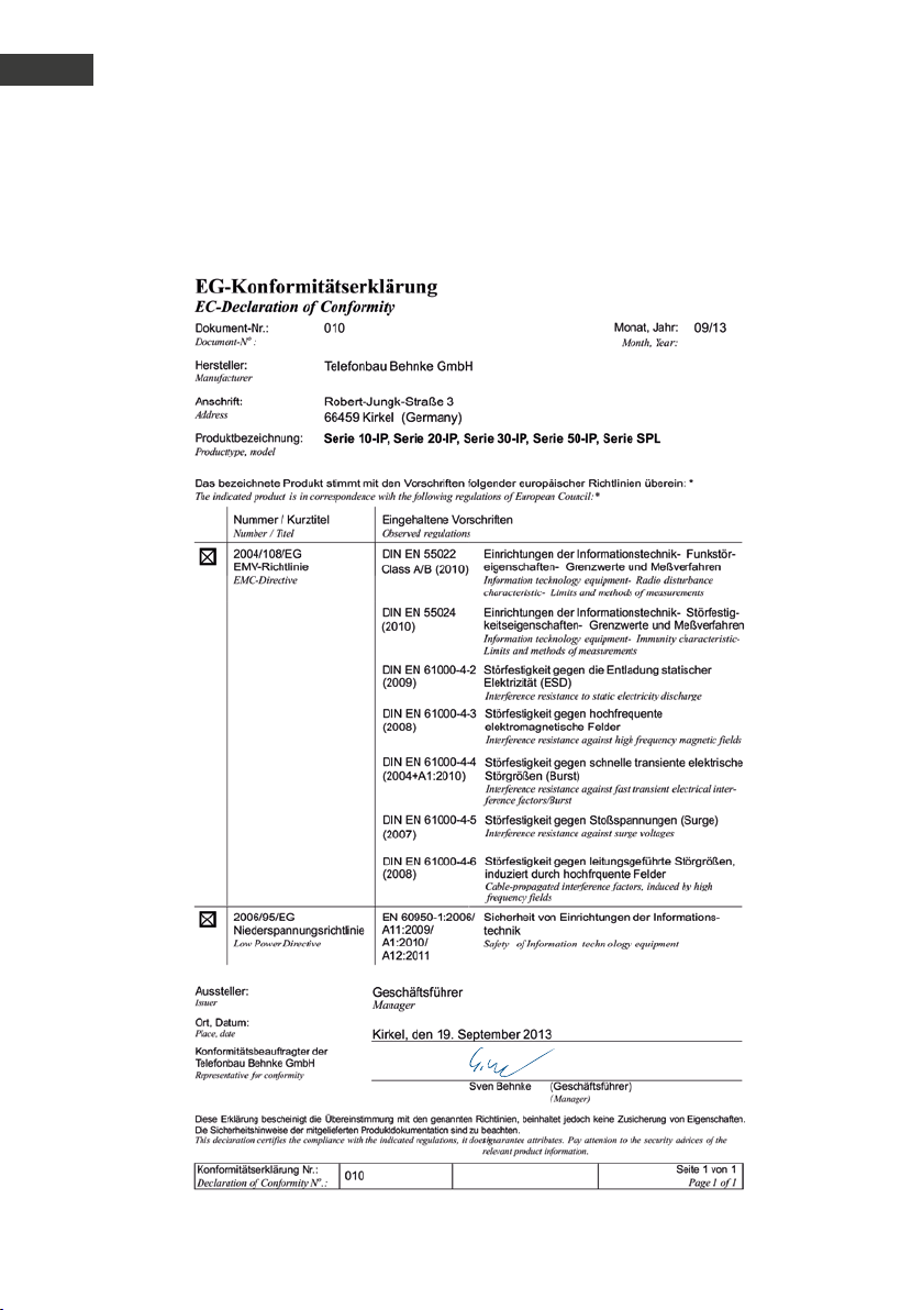
Manuel dʼutilisation Behnke SIP 2.0
F
Déclaration CE
7.
déclaration ce
76 www.behnke-online.fr
Page 77

8.
informations légales
Manuel dʼutilisation Behnke SIP 2.0
Informations légales
F
1. Nous nous réser vons le droit de modifier
nos produits en ver tu des progrès techniques.
En raison de lʼévolution technique, les
produits livrés peuvent avoir une apparence
différente de ceux présentés sur cette notice.
2. Toute reproduction ou reprise, même partielle, des textes, illustrations et photos de ces
instructions est interdite sans notre autorisation écrite préalable.
3. Cette documentation est protégée par les
droits dʼauteur. Nous déclinons toute responsabilité quant à dʼéventuelles erreurs de
contenu ou dʼimpression (y compris les caractéristiques techniques ou dans les graphiques
et dessins techniques).
Compatibilité électromagnétique
Directive sur les basses tensions
Informations relatives à la loi sur la responsabilité du fait des produits:
1. Tous les produits de notre gamme doivent
être utilisés conformément à lʼusage prévu.
En cas de doutes, il est impératif de demander
conseil à un professionnel ou à notre SAV (voir
numéro de la Hotline).
2. Débrancher tous les appareils sous
tension (et plus particulièrement en cas
dʼalimentation secteur 230V), avant de les
ouvrir ou de raccorder des câbles.
3. Les dommages directs ou indirects pro-
venant dʼinterventions ou de modifications
apportées à nos produits, ou résultant dʼune
utilisation non conforme sont exclus de la
garantie. Ceci vaut également pour les dommages causés par un stockage inapproprié ou
par toute autre influence extérieure.
4. Lors de la manipulation de la tension
secteur 230V ou de lʼutilisation dʼappareils
branchés sur le secteur ou fonctionnant sur
batterie, les directives en vigueur doivent
impérativement être respectées, par ex. les
directives relatives à la compatibilité électromagnétique ou aux basses tensions. Les
travaux correspondants doivent uniquement
être confiés à un professionnel conscient des
normes et risques.
5. Nos produits sont conformes à toutes les
directives techniques en vigueur, allemandes
et européennes, ainsi quʼaux lois sur la télécommunication.
77www.behnke-online.fr
Page 78

Manuel dʼutilisation Behnke SIP 2.0
F
Note
78 www.behnke-online.fr
Page 79

Manuel dʼutilisation Behnke SIP 2.0
Note
F
79www.behnke-online.fr
Page 80

Version 2.3
Kirkel, Juli 2014
TCB 1588_0913
telecom
behnke gmbh
Telecom Behnke GmbH
Gewerbepark „An der Autobahn“
Robert-Jungk-Straße 3
66459 Kirkel
Deutschland /Germany
Info-Hotline: +49 (0) 68 41/81 77-700
Service-Hotline: +49 (0) 68 41/81 77-777
Telefax: +49 (0) 68 41/ 81 77-750
[email protected]
www.behnke-online.de
 Loading...