

Page 1
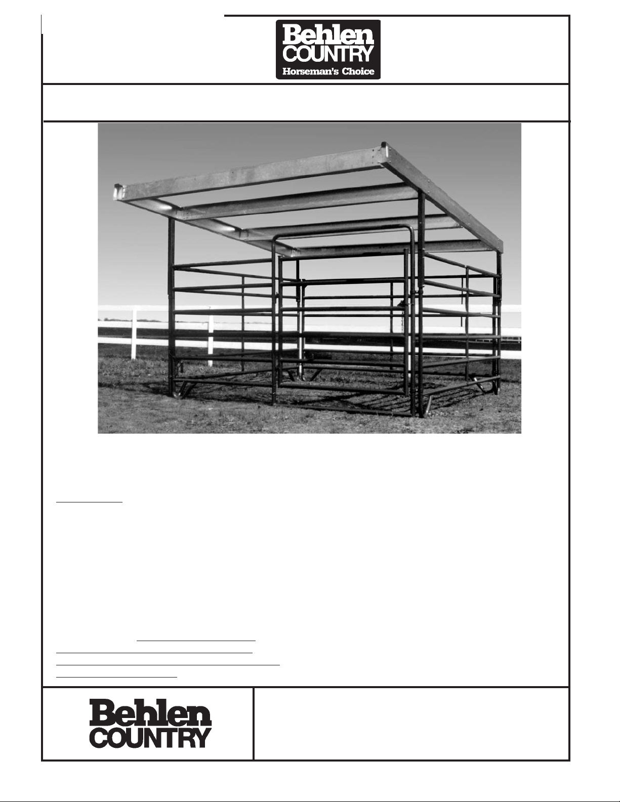
ASSEMBLY INSTRUCTIONS
Horse Shelter 12’ x 15’
76110678
THANK YOU FOR PURCHASING THIS PRODUCT
For questions about this product, or parts inquiries, please contact our Customer Service Center listed below.
Hardware Pkg.
76900228
Check with local government authorities to determine if a building permit is required.
Sheeting used must conform to these or greater
specifications as listed below:
Design Criteria
Snow – 40 psf ground snow
Wind – 90 MPH exposure C
Loads calculated in accordance with the Uniform
Building Code 94 Edition.
This shelter requires adequate anchoring to safely
resist the design wind forces and to avoid injury to
animals and others. Behlen Mfg. Co. offers an
anchor package as a separate accessory that will
be adequate when properly installed in heavy,
undisturbed soil. Behlen Mfg. Co. strongly
recommends that you consult a qualified
professional engineer to design the anchor for
your specific application.
Components for the Modular Shelter System as
provided by Behlen Country, have been designed
for ground snow loads of up to 40 psf and winds up
to 90 mph (Exposure “C”). The ability of these
shelters to safely resist these conditions is
dependant upon several factors beyond the
manufacturer’s control such as the uniformity of the
soil bearing support and the adequacy of wind
uplift anchorage.
These Modular Shelter Systems are not intended to
serve as permanent building structures and should
not be used as such. (For these reasons, an
engineering certification is not offered by Behlen
Mfg. Co.) Customers are responsible for verifying
ground snow load and wind load requirements in
the area in which the Modular Shelter Systems will
be constructed.
CUSTOMER SERVICE CENTER
PO Box 569
Columbus, NE
68602-0569
Ph: 1-800-447-2751
Fax: (402) 563-7447
F-19706-8 TECHNICAL INFORMATION 70 066 Rev. 6-24-05 6-1-01
Page 2
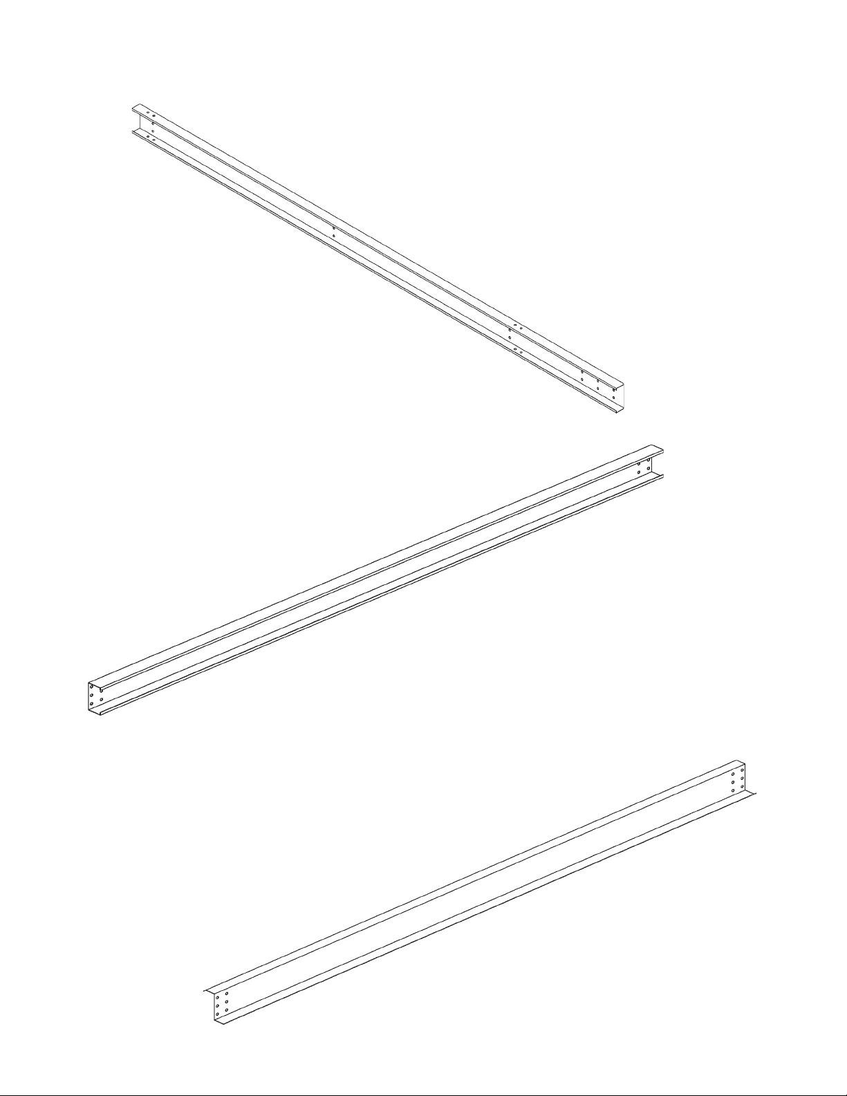
Component List for 12’ x 15’ Horse Shelter
Ref. No. 1
Part Number – 76603288
Cee 8” 12 Gauge Galv x 15’-4 5/8”
Qty. 2
Ref. No. 3
Part Number – 76602768
Zee 8” 14 Gauge Galv x 11’-7 7/8”
Qty. 2
Ref. No. 2
Part Number – 76602538
Cee 8” 16 Gauge Galv x 11’-7 7/8”
Qty. 2
F-19707-2 Rev. 8-26-03 6-1-01
Page 3
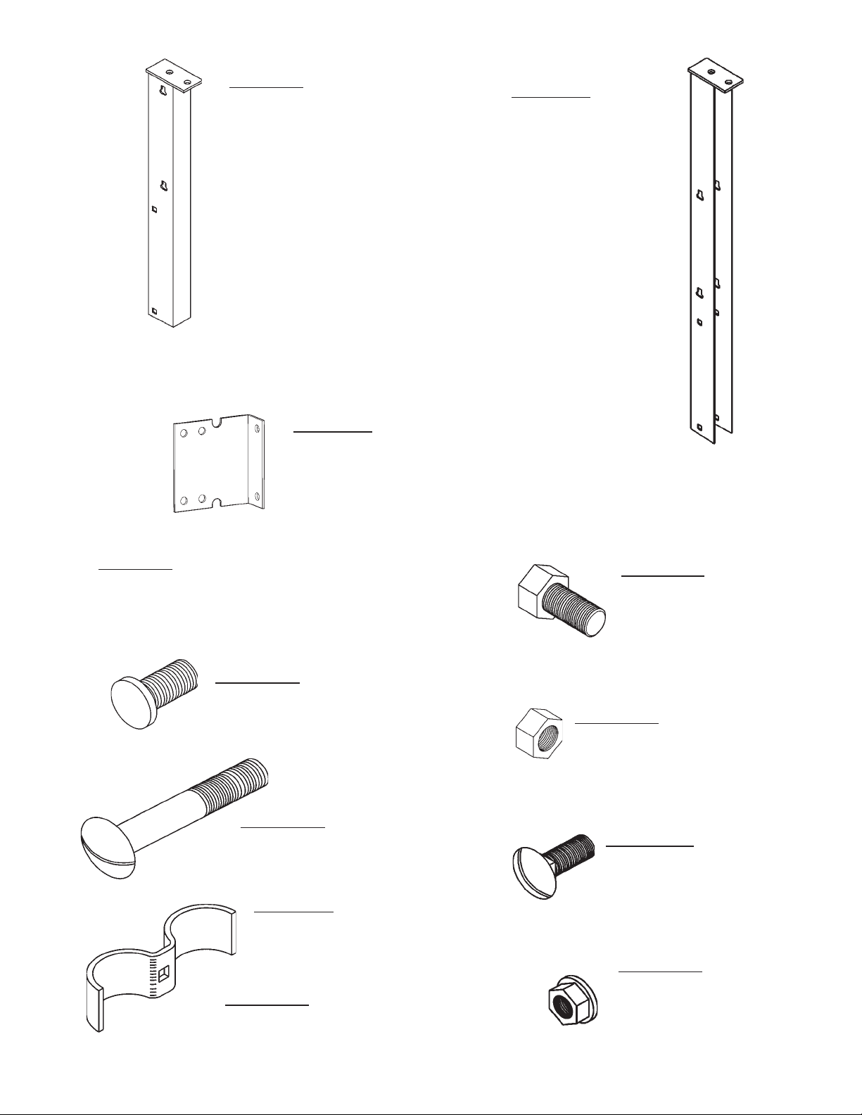
Ref.No. 4
Ref. No. 5
Part Number –
76400349
Short Shelter Post –
Hot-dipped
Galvanized
Ref. No. 6
Part Number – 76602558
Side Channel “L” Clip – Galv.
Qty. 8
Ref. No 7
Part Number – 76900097
Hardware Package for Horse Shelter
Part Number –
76400359
Tall Shelter Post –
Hot-dipped
Galvanized
Ref. No 7a
Hex Head Cap Bolt –
½” x 1” Plated
Qty. 24
Ref. No 7b
Flat Round Head Bolt –
½” x 1” Plated Qty. 16
Ref. No 7c
Nut ½” Hex Grade A Plated
Qty. 52
Ref. No 7d
Carriage Bolt ½” x 3” Plated
Qty. 12
Ref. No 7e
Carriage Bolt 3/8” x 1”
Plated Qty. 8
Ref. No 7f
Part Number – 76602507
2” Butterfly Connector
Half- Gray Qty. 16
Ref. No 7g
Nut 3/8” – Flanged
Ref. No 7h
Part Number – 76602837 (8 pair)
Whiz Lock – Plated
Qty. 8
Rubber Strip (Not Illustrated) Qty. 2
F-19708-3 Rev. 6-18-04 6-1-01
Page 4
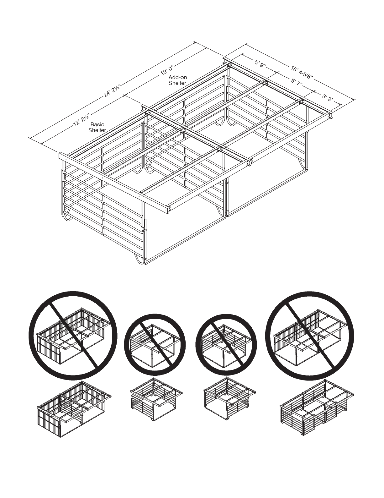
Roof Dimensions
CORRECT
USAGE
Proper Use of 12’ Open Support Brace
#76110697 & 76110699
CORRECT
USAGE
CORRECT
USAGE
CORRECT
USAGE
F-20163 6-18-04
Page 5
NOTE:
If you are planning on erecting an add-on section onto the shelter, read through both the
instructions. This will eliminate rework.
If sheeting will be installed, do not install it until all sections of the shelter are erected.
Step 1
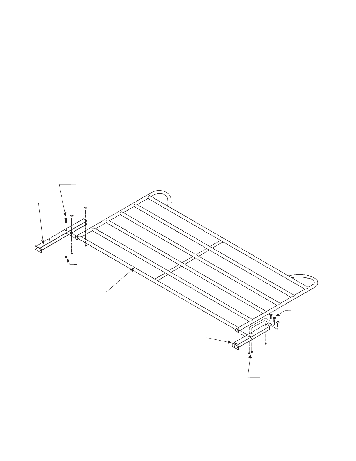
1a. For assembling ease, lay the panel down. Slide the tall shelter post (5) and the short
shelter post (4) onto the vertical 2” tube. If assembling the shelter on a 12’ XT Corral
Panel, be sure the cap rests in the three slots provided on the shelter posts.
1b. Fasten each shelter post (4 & 5) with three-½” x 3” plated carriage bolts (7d) and
three-½” nuts (7c).
NOTE:
When fastening, keep in mind,
which side of the corral panel will
be the inside of the pen. Place the
7d
bolt heads on the inside of the pen
to ensure a smooth surface for the
5
safety of the animal.
7c
12’ XT Corral Panel
OR
12’ Horse Stall Panel
NOTE: Each shelter post (tall and short) has
an extra set of key holes located toward the
top of the post. Use these holes only if you
want a short shelter height.
The assembly instructions are showing how
to set up a shelter using the bottom set of key
holes for the tall shelter height option.
7d
(3 req’d.
for
4
7c (3 req’d. for
each shelter post)
each
shelter
post)
F-19709 6-1-01
Page 6
Step 2
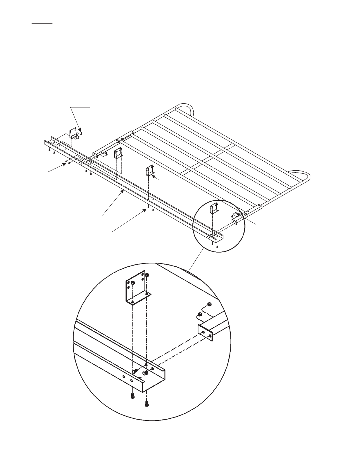
2a. With the corral panel still lying down, assemble the end cee (1) to the shelter posts using
four-½” x 1” hex head bolts (7a) and two-½” nuts (7c). Use the holes indicated on the
illustration. When assembling end cee onto a horse stall, use the holes as indicated in
Detail A.
2b. Assemble the side channel clips (6) to the end cee using two-½” x 1” flat round head
bolts (7b) and two-½” nuts (7c). Be sure to keep the bolt heads to the outside of the cee
as shown. Position the clips in the direction as shown.
7c
(2 req’d. at each
clip location)
7a
(4 req’d. for
each end cee)
6
(4 req’d. for
each end cee)
1
7b
(2 req’d. at each
clip location)
7c
(4 req’d. for
each end cee)
Detail A
F-19710-3 Rev. 8-26-03 6-1-01
Page 7
Step 3
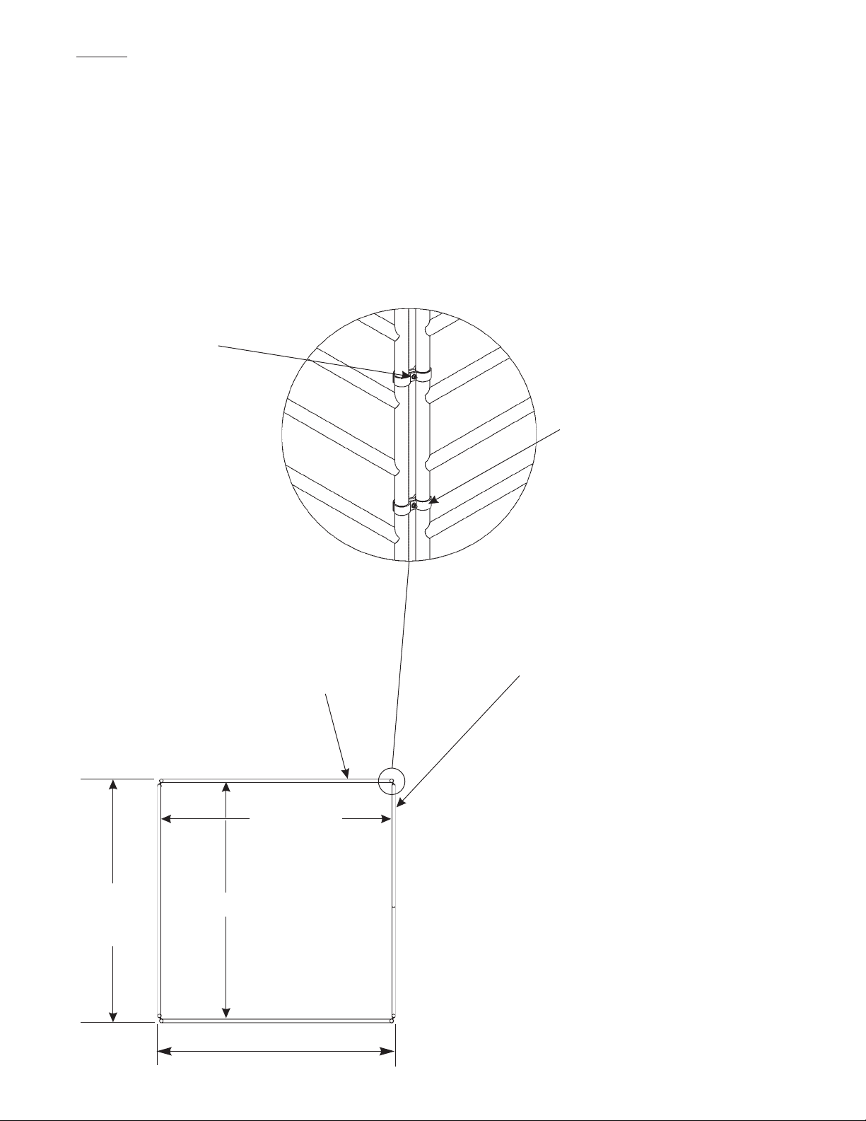
3a. At this point, the structure can now be set in place. Two people are needed for this
process for safety purposes. Place four-2” butterfly connector halves (7f) at each corner
of the pen. Fasten the butterflies with one-3/8” x 1” carriage bolt (7e) and one-3/8”
flanged whiz nut (7g). Make sure the bolt head is on the inside of the pen for a smooth
edge near the animal. Do not fully tighten the butterflies. This will allow for adjustment of
the pen. When attaching the butterflies, place one directly below the shelter post and one
near the bottom of the panel.
3b. Measure the pen to match the measurements provided in the illustration. After
measuring and moving panels as necessary, tighten the butterflies in place.
7g&7e
(16 req’d. for a
12’ x 12’ pen)
7f
(16 req’d. for a
12’ x 12’ pen)
The sides are the panels that have
the shelter posts, end cee and
side channel clips attached to it.
Be sure that the front panel is
located on the side that contains
the tall shelter posts. This will
ensure enough clearance for
you and the animal.
11' 11-9/16"
12' 2"
Outside
11' 10"
Dim.
Front
Back
(Doorway)
12' 3-9/16"
Outside Dim.
F-19711-3 Rev. 6-24-05 6-1-01
Page 8
Step 4
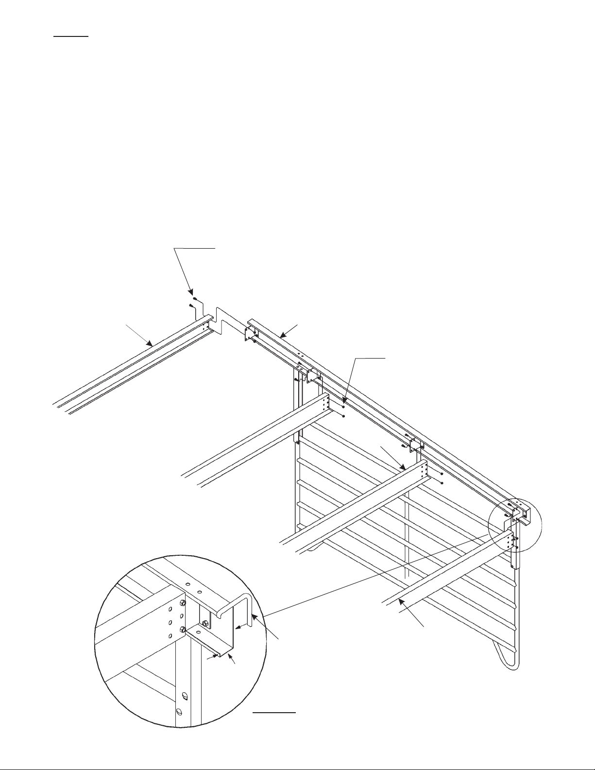
Once the pen is set in place, it is now time to assemble the interior cees and zee. Two people
are needed for this process for safety purposes.
4a. To begin, start on the low side. Lift the 8-inch cee (2) up to the bottom clips and rest on
the side channel clips. Be sure that the 8-inch cee (2) is positioned as shown on the
illustration. The open face of the 8-inch cees has to face into the pen. Fasten at each
end with two-1/2” x 1” hex head bolts (7a) and two-1/2” nuts (7c).
4b. Follow the same instructions for the 8-inch zee (3) and the high side 8-inch cee (2). Make
note of the position to ensure proper assembly.
4c. Insert the rubber strip (7h) around the entire end of the end cee on the low side. See
Detail B. Cut any excess rubber strip off. Repeat this process for the other side. This will
take away any sharp edge that could endanger your animal.
7c (2 req’d. at each
structural to clip connection)
2
Partial view
shown
for clarity
purposes
1
7c (2 req’d. at each
structural to clip connection)
3
Trim with rubber
2
strip (7h). Repeat
on other end cee.
Detail B
F-19712-2 Rev. 8-26-03 6-1-01
Page 9
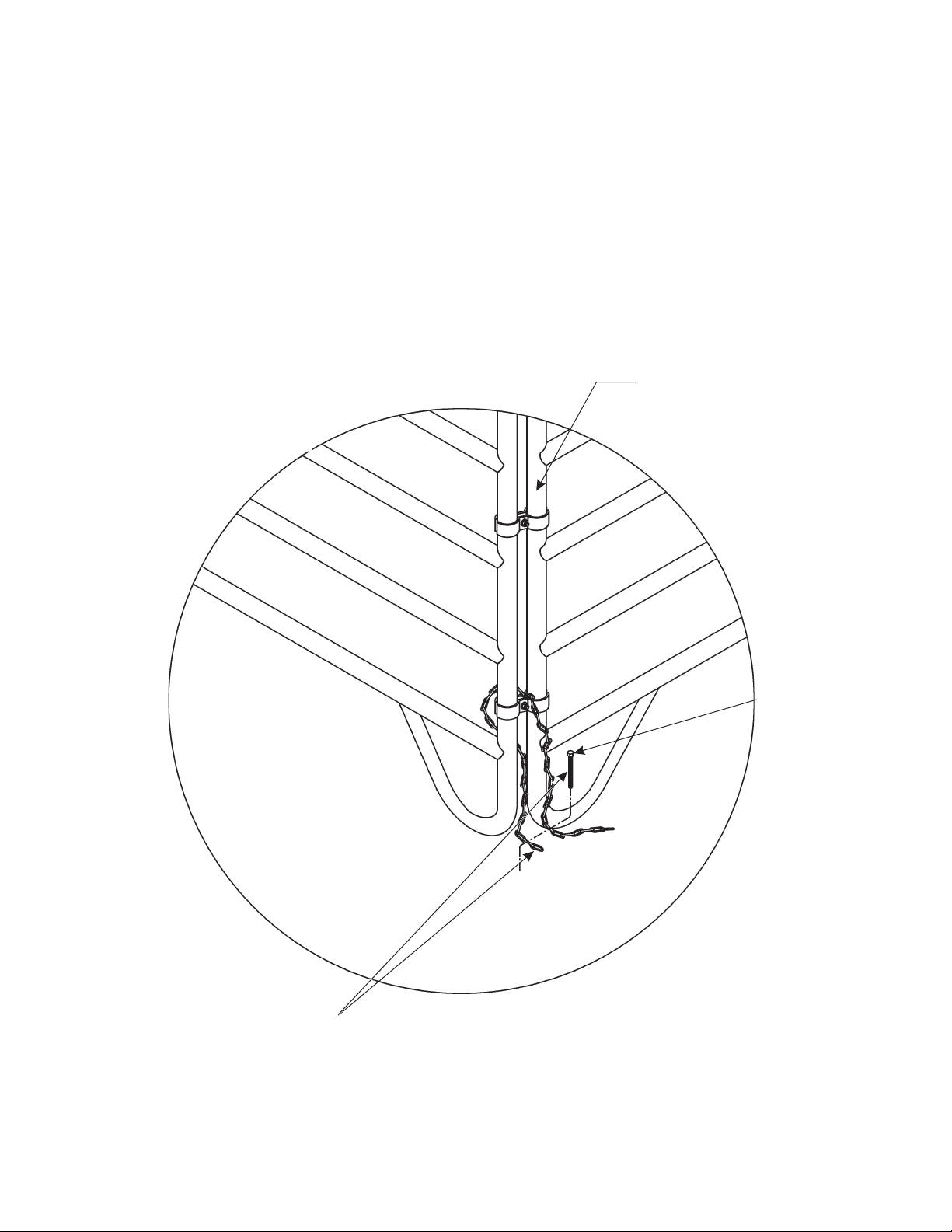
Anchoring the Assembled Horse Shelter
The assembled horse shelter will require anchoring. For anchoring into undisturbed soil,
Behlen Mfg. Co. offers an optional anchoring package specifically designed for the horse
shelter. To order this package contact customer service at: 1-800-447-2751.
Ask for part number: 76110667; Anchor Package for Horse Shelter.
When anchoring into concrete, all materials will be supplied by the buyer and can be bought
at any local hardware store. The shelter must be anchored at every corner. With a 90-MPH
wind, an uplift force of 2,200 pounds per corner can be created.
Typical detail of installation in
a concrete situation.
Assembled Horse Shelter
Slip the bolt
through the
chain loops.
Chain and Anchor Bolt can be
purchased at your local hardware store.
(Chain and Anchor Bolt must be
capable of withstanding a maximum
uplift force of 2,200 pounds per corner).
F-19713-1 Rev. 2-25-04 6-1-01
Tighten the chain as much as
possible when anchoring.
Cut off any excess links of chain.
 Loading...