

Page 1
ASSEMBLY INSTRUCTIONS
Energy-Free Waterers
SF-2C, SF-4C, EF-1C, EF-2C, EF-4C
THANK YOU FOR PURCHASING THIS PRODUCT
For questions about this product, or for parts inquiries, please contact our Customer Service Center listed below.
CONGRATULATIONS, you have just
purchased one of the most efficient
Energy-Free waterers ever manufactured.
The thermos bottle type construction will
hold the heat from the earth temperature
of the water and keep your Energy-Free
waterer warm in the winter and cool in the
summer. The closed dark interior inhibits
growth of bacteria, scum and algae.
Energy-Free
Waterer
SF-2C 20 40
SF-4C 30 80
EF-1C 12 15
EF-2C 20 20
EF-4C 30 30
Minimum Number
of Animals
Gallon
Capacity
The smooth rounded plastic exterior is
maintenance free and prevents injuries to
animals. It also prevents tongue injuries
from frigid steel.
All Behlen Country Energy-Free
Waterers carry a 5 year limited
warranty on the body and a 1 year
limited warranty on valves and
controls.
Installation and Recommendations
Please read over these instructions to make
sure you have all
your installation. To ensure proper operation
in cold weather, it is highly recommended
you purchase the optional Poly Earth Tube and
Shut-off Valve Kit. Contact your dealer for
necessary items.
The Energy-Free waterer depends on water
entering the unit at ground temperature
(50-55° F.). This generally requires the 3/4" water
line to be at least 2 ft. below the frost line for
maximum performance.
Also, a minimum number of animals must use the
waterer to ensure that enough fresh water is
cycled through the waterer daily to prevent
freezing.
necessary components for
that
Under certain conditions, some icing may occur
on top of the balls in cattle units. Periodically
remove the ice with hot water or by tapping on the
balls, physically removing any ice.
We recommend a Behlen Insulated Earth Tube be
used. Where a waterer is replacing an electric
waterer and the Poly Earth Tube is less than 12"
deep and uninsulated, you may need to use heat
cable in the riser pipe. A 250 watt submersible
heater (52120088) is available for use when less
than the minimum number of animals are using
the waterer.
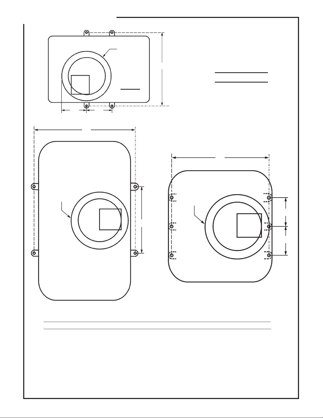
The drawings in these instructions provide slab
dimensions and approximate anchor locations for
various models. It is advisable to check the
waterer for exact dimensions for anchor locations.
This is because some variance due to the molding
process is normal and the dimensions on the
waterer may vary slightly from the drawing. Anchor
bolts (not provided) may be set in concrete or
anchors may be drilled in after the fountain is set
in place. Use anchors for 5/16" bolts. NOTE: The
slab should be at least 4" larger than the waterer
on all sides.
Poly Earth Tube Installation Instructions
Your insulated Poly Earth Tube is designed to
contain the earth’s heat from below the frost line,
and keep the frost from penetrating through the
tube and freezing the water pipe.
CUSTOMER SERVICE CENTER
PO Box 569
Columbus, NE 68602-0569
F-19857-8 TECHNICAL INFORMATION 70 110 Rev. 6-8-09 8-4-04
Ph: 1-800-447-2751
Fax: (402) 563-7447
Page 2
ASSEMBLY INSTRUCTIONS
After you have all necessary components for this
installation, dig a trench below the frost line from
the water source to where the waterer will set.
Dig out about a 16" diameter hole beneath the
waterer for the 12" diameter Poly Earth Tube.
Refer to the diagrams on the next pages for water
pipe connection. NOTE: Install Shut-off Valve at
an easily accessible location.
If you have clay soil or a soil that does not drain
well, you will need to place about a foot of coarse
gravel for pipe drainage at the bottom of the hole.
Connect several Poly Earth Tubes together to
achieve your desired depth. Follow the installation
instructions on the label of the Poly Earth Tube.
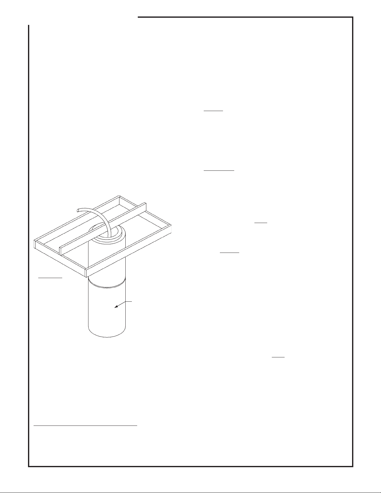
The Poly Earth Tube needs to be kept flush with
the top of your cement slab. Set the outside frame
of cement form and place a straight board or pipe
across the center of the hole. (see Figure 1
below).
Remove the lid(s) and float balls from the waterer.
Locate the hardware package, it is generally
attached to the rim of the waterer body.
Attach the four Tie Down Brackets with the four
5/16" x 1½" lag screws. Use the small hole for
mounting to the waterer, the large hole will be used
for mounting to the concrete pad. DO NOT OVER
TIGHTEN LAG SCREWS. Just snug the bracket up
to the body.
NOTE:
These Tie Down Brackets are not required
on the SF-4C. The SF-4C has molded-in mounting
pads.
Turn the waterer upside down and place caulking
around the outer bottom edge. Make sure the
caulking is heavy enough to seal any irregularities
between drinker and cement.
CAUTION:
Any air leakage in this area could
result in a frozen riser pipe.
Set in place with water line extended up through
tunnel. Anchor to concrete.
Slide insulating tube over water line and clamp with
plastic tie. Connect valve to water line and clamp
into position. DO NOT
OVER TIGHTEN BOLTS.
Figure 1
Poly Earth
Tube
Extension
Attach the Earth Tube to board by using long
screws or by plugging wire into the sides of the
tube and tying the tube to the board.
Back fill around the outside of the Poly Earth Tube
lightly at first, making sure the tube stays level at
the top. Continue to fill and tap lightly until hole
around the pipe is completely full. Avoid large
clods or rocks in this fill area. Pour the cement
level with the top of the Poly Earth Tube.
Make sure all waterline connections are tight.
Turn on water and adjust valve for desired water
level. NOTE:
The waterer is equipped with a
Franklin Valve. This is an easy-to-maintain valve
with an operating range of 0 to 55 psi. It will work
with pond or low pressure gravity feed systems. If
increased flow is desired, a larger replacement
orifice (54300968) is available. If a gravity feed
system is used and more flow is desired, a low
pressure, high-flow valve (54130338) is available.
On units with ball closures, the 10" balls are preweighted and foam filled to facilitate closing and
make it easier for smaller animals to access the
water. No further adjustment of ball weight should
be necessary.
Replace float cover. DO NOT
OVER TIGHTEN THE
TWO COVER BOLTS.
When animals are first exposed to a ball unit, lower
the water level approximately 1” to 2” so that the
ball floats freely. This allows the animals to learn
where the water is and how to drink from it.
Waterer Installation Instructions
Remove valve cover and remove float valve
assembly. Disconnect the hose assembly from
the valve if the hose is attached. (In some models,
the hose is separate from the valve assembly.)
F-19858-6 Rev. 6-8-09 8-18-04
Page 3
ASSEMBLY INSTRUCTIONS
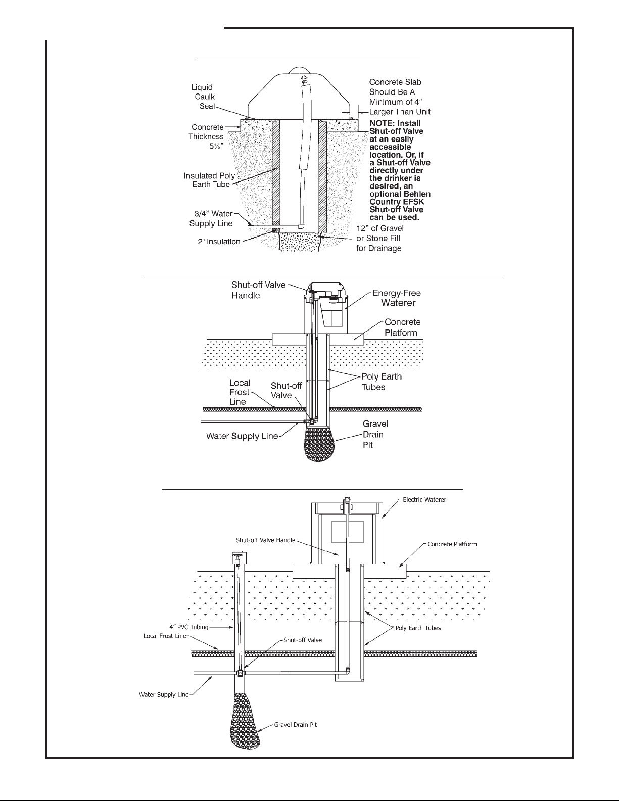
Typical setup without Shut-off Valve
Typical setup with the EFSK Shut-off Kit inside Earth Tube
Typical Remote setup with the EFSK Shut-off Kit
F-20560-1 Rev. 6-8-09 1-10-08
Page 4
ASSEMBLY INSTRUCTIONS
EARTH
TUBE
EARTH
TUBE
A
CONCRETE PAD
SPECIFICATIONS
FF-1C
B
B
A
A
EARTH
TUBE
B
B
FF-2C
FF-4C
SF-4C
SF-2C
Model A B Min. Slab. Size
FF-1C 21-1/2” 8” 29” x 34”
FF-2C 21-3/4” 18” 28” x 44”
FF-4C 36-1/2” 18” 44” x 44”
SF-2C 27-3/4” 22” 30” x 48”
SF-4C 42-1/2" 11" 48" x 48"
B
F-19859-3 Rev. 3-5-09 8-9-02
Page 5
ASSEMBLY INSTRUCTIONS
Hardware Pkg.
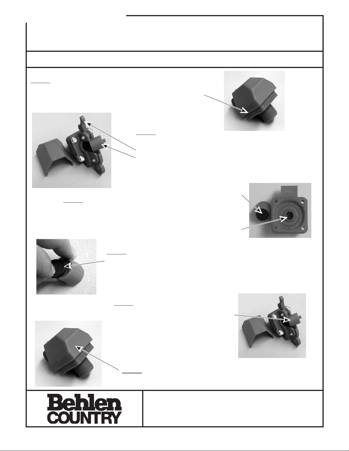
Cleaning the Franklin BV Valve and
54300978
Replacing the Plunger & Seal
THANK YOU FOR PURCHASING THIS PRODUCT
For questions about this product, or for parts inquiries, please contact our Customer Service Center listed below.
STEP 1
Remove the packaging tape from around the top of the valve.
STEP 2
Slide off cover,
pivot upper arm up,
and remove the plunger.
STEP 3
Clean the rubber part of the plunger and opening to the
valve of any mineral deposits or dirt buildup that may be
obstructing the normal operation of the valve.
STEP 4
If the rubber seal is grooved but still pliable (not hard and brittle), you may
flip it over and use the backside of the seal. If both sides of the seal are
hard, replace both the plunger and the seal.
STEP 5
Replace the plunger with the nipple facing you
and the rubber facing the valve.
Rubber
Valve
Opening
STEP 6
Replace the cover to complete the cleaning of the valve.
CUSTOMER SERVICE CENTER
PO Box 569
Columbus, NE
68602-0569Ph: 1-800-447-2751
F-20201 TECHNICAL INFORMATION 70115 11-4-04
Fax: (402) 563-7447
www.behlencountry.com
Page 6
ASSEMBLY INSTRUCTIONS
F-20441 4-7-06
Page 7
ASSEMBLY INSTRUCTIONS
Instructions How To Assemble The Float And Arm To
The Franklin BL Valve And How To Adjust The Valve
The Franklin Valve is already attached to the waterer. The float and arm assembly is with the hardware
kit. They are packaged separately to prevent undue wear to the valve caused by the arm bouncing up
and down during shipping.
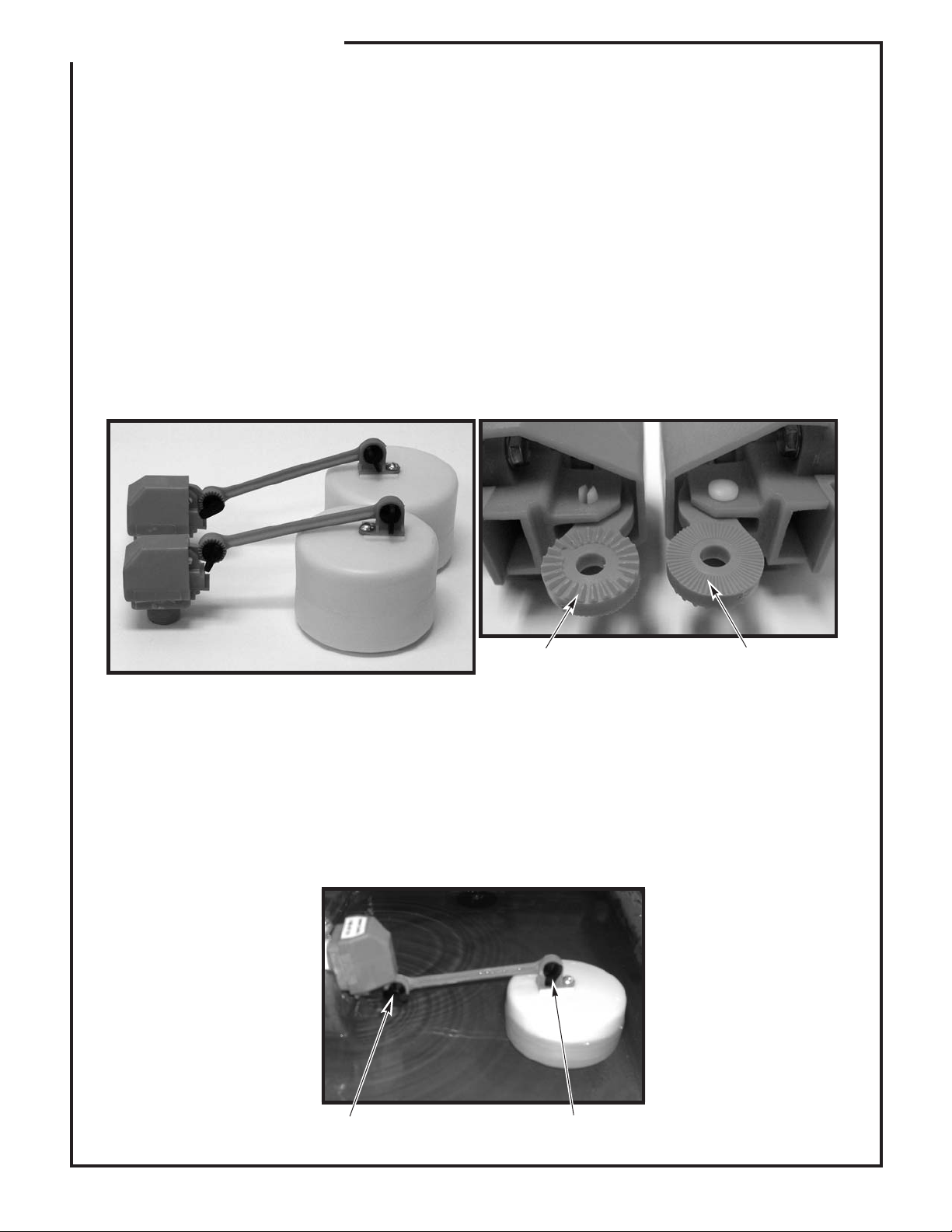
The float and arm are attached to the valve by a thumb screw. The float can be positioned either closer
or further away from the valve (see photo below left for the two float positions). Further away increases
the shut off force of the valve. However depending upon which waterer is being used, the closer position
may be required to maintain proper clearance for the float to the side of the waterer. A clearance of at
least 1/2" should be maintained to ensure smooth operation of the valve.
When attaching the float arm to the valve, be sure to attach the arm to the correct side of the valve. The
grooves on the valve and float arm must match. Please note that the valve has coarse grooves on one
side and fine grooves on the other. The fine grooved side is used with the float arm (see below right for
details).
Coarse Fine
To adjust the water level in the waterer, loosen the thumb screws and position the float and arm so that
the valve is turned off when the water is at the desired level (see photo below). It may take a couple of
adjustments to get the correct level (1-1½" below the top of the trough). To speed the adjustment
process, remove the drain plug and drain a little water out so that the valve turns on. Put the drain plug
back and let water fill until the valve shuts off. If the level is not correct, repeat the process until the
correct level is obtained and then replace the float cover. Your waterer is now ready for use.
Adjust Adjust
F-20569 3-17-08
 Loading...