

Page 1
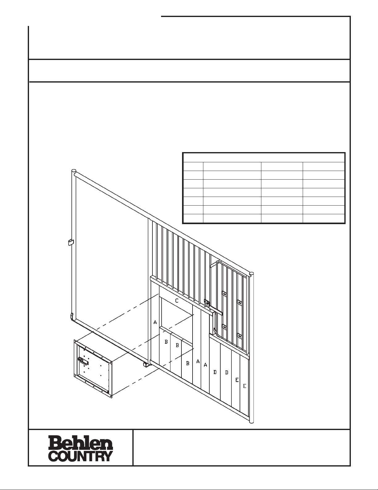
ASSEMBLY INSTRUCTIONS
Hardware Pkg.
Swing Out Door F/PHSW
54150108
Thank you for purchasing this product.
For questions about this product, please contact the Customer Service Center listed below.
1. Install customer supplied wood into the bottom of the stall using the cut size and board
placement chart below.
2. Place the Swing Out Door into place. At the same time, install board C.
3. Use customer supplied 3/8” wood screws and fasten the feeder in place.
4. Optional reinforcement plate can be used to help secure the feeder in place. If used, drill holes
through the wood and attach feeder frame and reinforcement plate with 3/8” x 2” bolts and nuts
supplied in the hardware bag.
10’ STALL WOOD CHART
Ref. Wood Size Stall - Qty. Door - Qty.
A 2” x 6” x 47½” 3 7
B 2”x8”x23” 3 --C 2” x 8” x 21¼” 1 - - D 2” x 8” x 35½” 2 - - E 2” x 8” x 35½” 2 - - F 2” x 8” x 47½” - - - 1
10’ Horse Stall Front
54900038
Customer Service Center
4025 E. 23rd St.
Columbus, NE
68602-0569
F-19663-2 Technical Information 70065 Rev. 11-29-01 11-21-00
Ph: 1-800-447-2751
Fax: 402-563-7447
www.behlencountry.com
Page 2
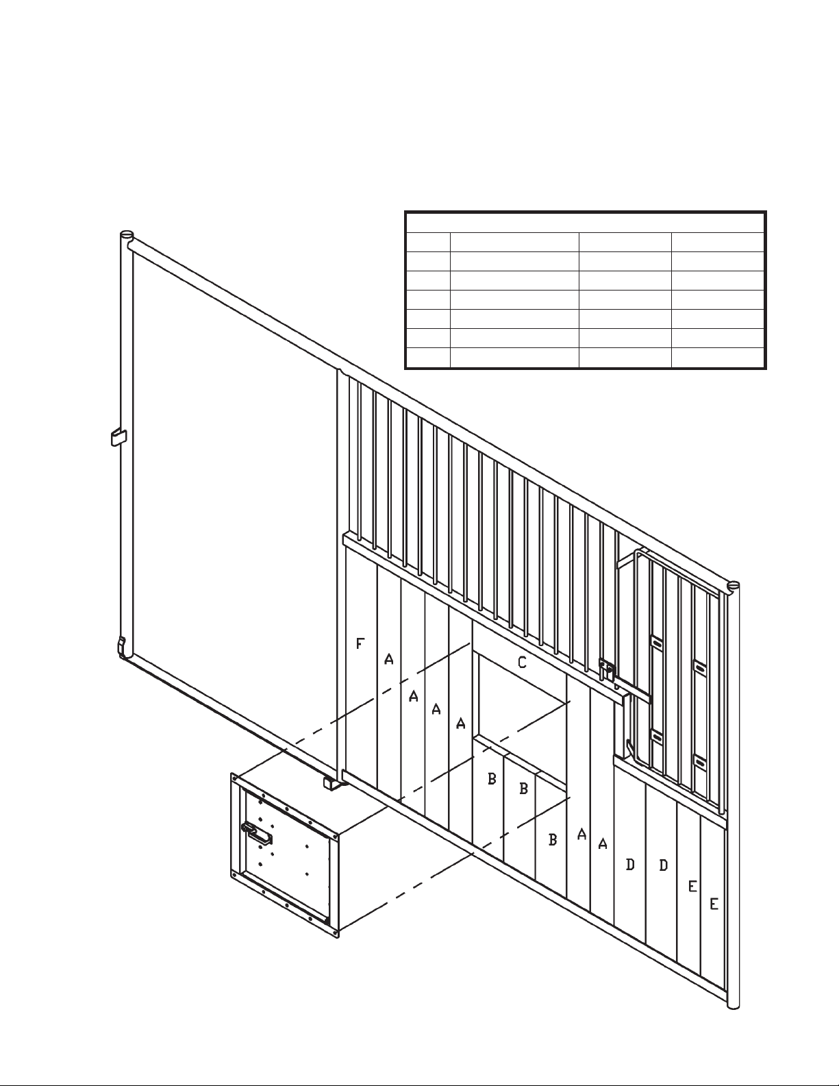
1. Install customer supplied wood into the bottom of the stall using the cut size and board
placement chart below.
2. Place the Swing Out Door into place. At the same time, install board C.
3. Use customer supplied 3/8” wood screws and fasten the feeder in place.
4. Optional reinforcement plate can be used to help secure the feeder in place. If used, drill holes
through the wood and attach feeder frame and reinforcement plate with 3/8” x 2” bolts and nuts
supplied in the hardware bag.
12’ STALL WOOD CHART
Ref. Wood Size Stall - Qty. Door - Qty.
A 2” x 6” x 47½” 6 7
B 2”x8”x23” 3 --C 2” x 8” x 21¼” 1 - - D 2” x 8” x 35½” 2 - - E 2” x 8” x 35½” 2 - - -
F 2” x 8” x 47½” 1 1
12’ Horse Stall Front
with wood installed
F-19664-1 Rev. 11-29-01 11-21-00
Page 3
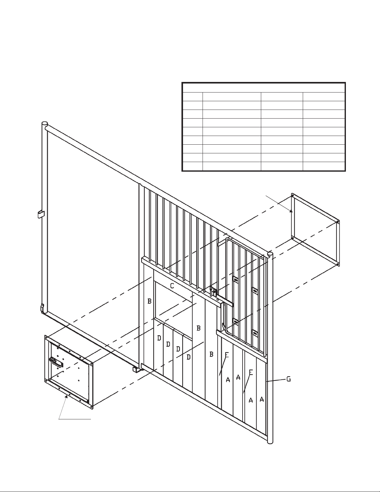
1. Install poly boards into the stall front and door (door not shown in illustration). See chart below for
reference guide.
2. Place Swing Out Door F/PHSW into the opening. At the same time, install board C. Mark the
locations of the four outside holes and then drill through the poly using a 7/16” dia. drill bit.
3. Place the Poly Reinforcement Backing Frame into place and bolt the backing frame to the
Swing-out Door Frame using the 3/8” x 2” bolts supplied in the hardware bag. (See illustration
below for reference).
10’ POLY BOARD CHART
Ref. Wood Size Stall - Qty. Door - Qty.
A 2” x 6” x 35½” 4 - - B 2” x 6” x 47½” 3 8
C 2”x6”x22” 1 --D 2” x 6” x 24¾” 4 - - E 2” x 2” x 35½” 2 - - -
F 2”x2”x47” --- 1
G 1” x 2” x 35½” 1 - - H 1” x 2” x 47½” - - - 1
10’ Front Horse Stall
with poly boards installed
Reinforcement
Backing Frame
Swing Out Door F/PHSW
F-19665-1 Rev. 11-29-01 11-21-00
Page 4
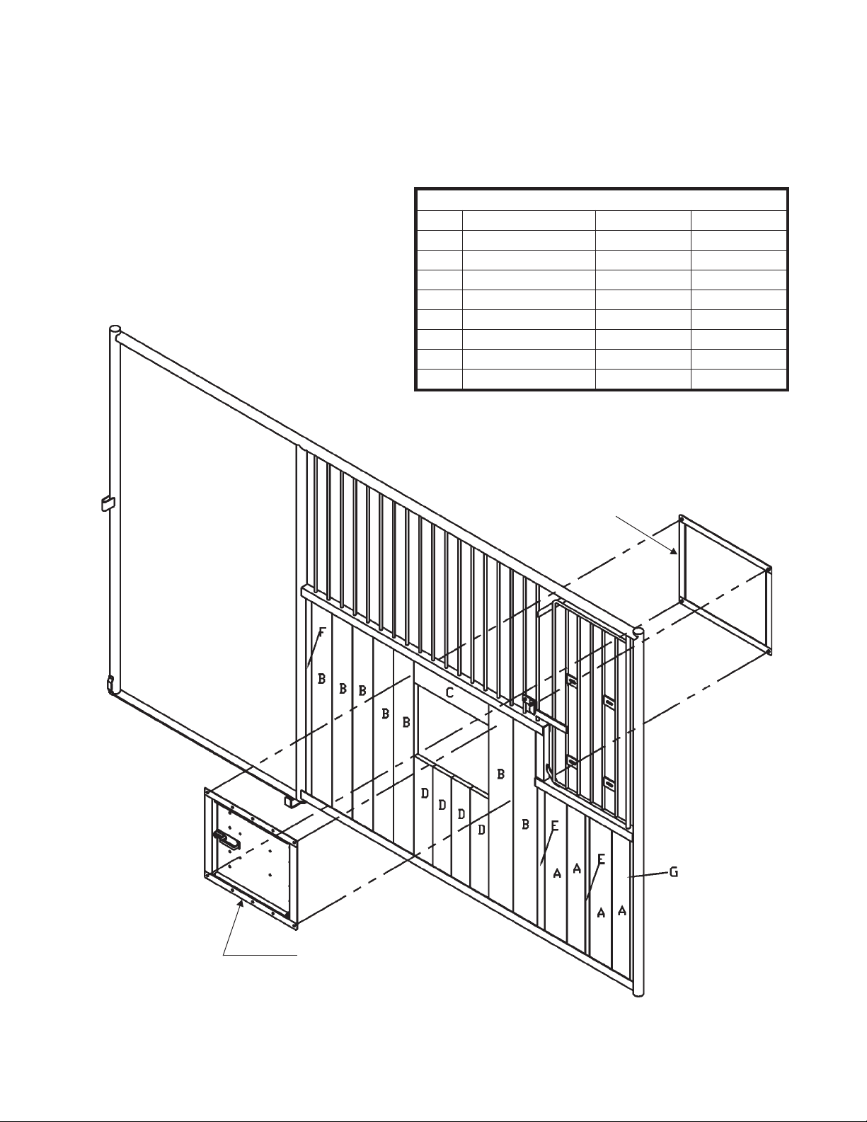
1. Install poly boards into the stall front and door (door not shown in illustration). See chart below for
reference guide.
2. Place Swing Out Door F/PHSW into the opening. At the same time, install board C. Mark the
locations of the four outside holes and then drill through the poly using a 7/16” dia. drill bit.
3. Place the Poly Reinforcement Backing Frame into place and bolt the backing frame to the
Swing-out Door Frame using the 3/8” x 2” bolts supplied in the hardware bag. (See illustration
below for reference).
12’ POLY BOARD CHART
Ref. Wood Size Stall - Qty. Door - Qty.
A 2” x 6” x 35½” 4 - - B 2” x 6” x 47½” 7 8
C 2”x6”x22” 1 --D 2” x 6” x 24¾” 4 - - -
E 2” x 2” x 35½” 2 - - -
F 2” x 2” x 47½” 1 1
G 1” x 2” x 35½” 1 - - H 1” x 2” x 47½” - - - 1
12’ Front Horse Stall
with poly boards
installed
Reinforcement
Backing Frame
Swing Out Door F/PHSW
F-19666-1 Rev. 11-29-01 11-21-00
Page 5
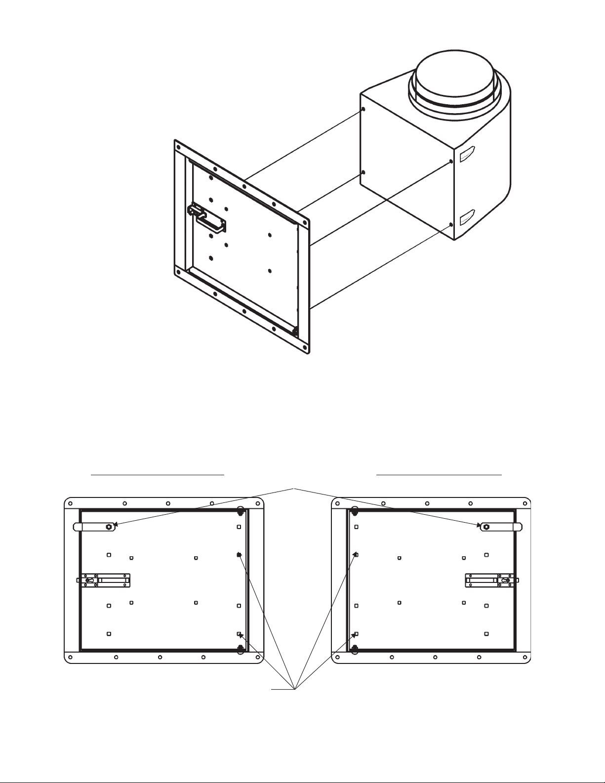
Installing the Bucket Holder
Use four 3/8” x 1½” carriage bolts and four
3/8” whiz lock nuts to attach the bucket
holder to the door using the bottom set of
holes as indicated below. Bolts and nuts are
found in the hardware bag.
Right-hand operated door Left-hand operated door
When mounting the poly bucket holder use
the bottom set of square holes.
Attach Door
Stop Bracket
using 3/8” x 1”
Carriage Bolt
and 3/8” Lock
Nut
For a left-hand operated door, simply
rotate the door and frame so that the
handle and latch are on the right side of
the assembly.
F-19667-1 Rev. 6-8-01 11-21-00
 Loading...