

Page 1

ASSEMBLY INSTRUCTIONS
Hardware Pkg.
Extreme Weather Poly Electric Drinker
Model EWPED (54150158)
THANK YOU FOR PURCHASING THIS PRODUCT
For questions about this product, or for parts inquiries, please contact our Customer Service Center listed below.
24900158
Before beginning, please read the instructions
thoroughly to make sure you have all of the
necessary components for your installation.
Location of the Drinker
If you are installing your drinker in a new
location some things can be done to enhance
the performance of your drinker and lower your
operating costs. If the drinker can be located
in a sheltered area, especially shielded from
the north wind, then the heater will need to
operate less and livestock will be more likely to
drink more.
However, we realize that it is not always
possible to locate the drinker in a sheltered
area, but even if the drinker is exposed and out
in the open, it would still be advantageous by
locating the drinker with the access door to the
south.
Water Supply Line
When installing your drinker please comply
with all local plumbing codes. The horizontal
underground water supply line should be ¾”
with a ¾” supply riser pipe. A ¾" I.D. pressure
hose is supplied with your drinker. We
suggest connecting the flex hose with 3/4" NPT
x 3/4" hose barb connectors and hose clamps
(these can be purchased locally) to the riser
pipe.
If desired, a shut-off valve can be installed
under the drinker to allow for easier servicing.
Note:
the winter, a means must be provided to drain
the supply line down below the frost line to
prevent freezing of the riser pipe. Tip:
Country has a shut-off valve kit (54130118) that
can be used to shut off the water supply and
drain the riser pipe.
If the heat is going to be shut off during
Behlen
Before hooking up your drinker, the supply line
MUST BE
contaminates will foul the valve upon start up of
your drinker. NOTE:
with a Franklin BL valve that is easy to clean
and adjust. If low water pressure conditions
exist and a higher flow rate is desired, a larger
inlet is available (3888247).
Preparing the Mounting Platform
Install the drinker on a 4" (minimum) thick
concrete base, slightly raised above the
ground level for better drainage. (Note: The
pad should be a minimum of 4” larger than the
drinker.) For the EWPED Drinker, a 24” x 34”
minimum pad is required. If you are replacing
a drinker and going to use an existing platform
made for a different drinker, it must have a 24”
x 34” flat mounting area. If it doesn’t have a
large enough area, you can pour a cap over
the existing platform to enlarge it or replace the
platform.
Extending the platform provides animals with a
secure place to stand while drinking. If you
extend the platform beyond the minimum it is
advisable to slope the platform outside of the
mounting area to promote better drainage. A
smooth surface is recommended for the
mounting area of the drinker and rough surface
on the area where the animals will stand to
drink. If you are pouring a new platform you
have the option of using anchor bolts set into
the concrete when wet or drilling and using
expandable anchor bolts after the concrete has
cured to mount your drinker. Refer to
illustration # 1 for detailed measurements of
the hole pattern.
flushed to ensure that no
Your drinker is equipped
CUSTOMER SERVICE CENTER
PO Box 569
Columbus, NE
68602-0569
F-20404-1 TECHNICAL INFORMATION 70118 Rev. 11-12-08 10-3-05
Ph: 1-800-447-2751
Fax: (402) 563-7447
www.behlencountry.com
Page 2
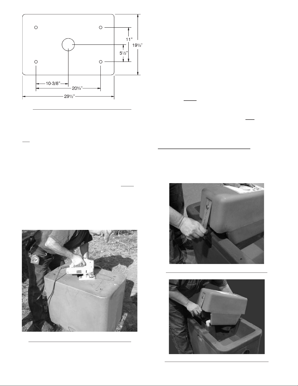
Illustration #1 - Anchor Bolt Placement
Before pouring the concrete, have the water line
routed up through a 4" or larger tile in the center
of the pad for final connections to the drinker.
Tip
: Behlen Country poly earth tubes (54130038)
are an excellent way to route water to your
drinker. Also, if electrical power is going to be
routed underground to your drinker, an
appropriate conduit for the electrical service must
be installed at this time also. Please follow local
electrical codes and use the recommended
materials to route power to your drinker. Note:
you are using an existing platform and the water
supply line is not in the center of the platform,
you can enlarge the existing opening as required
with a jig saw. If this is done, it is recommended
that the exposed foam be coated with silicone
sealant. See illustration 2 for details.
must be left open to give access to warmer air
from below the frost line, thus preventing the
riser from freezing. If the soil in your area does
not drain well it is recommend that a gravel bed
be used under the earth tube to promote
drainage if water happens to get in the earth
tube. The top of the earth tube should be flush
with the platform to allow flush mounting of the
drinker.
Be sure the riser pipe does not touch the sides of
the earth tube. If desired, a shut-off valve can be
installed under the drinker to allow for easier
servicing. Note:
If the heat is going to be shut
off during the winter a means must be provided
to drain the supply line down below the frost line
to prevent freezing of the riser pipe. Tip:
Behlen
Country has shut-off valve kit (54130118) that can
be used shut off the water supply and drain the
riser pipe.
Mounting the Drinker to the Platform
To make mounting your drinker easier it is best
to disassemble it first. Remove the float cover by
pulling out on the two latches, see illustration 3A
and 3B.
If
Illustration # 3A - Pull on Latch Hnadles
Illustration #2 - Enlarge Hole As Needed
Make sure the tile or earth tube extends below
the frost line for your area. The tile or earth tube
F-20405 10-3-05
Illustration # 3B - Removing Float Cover
Page 3
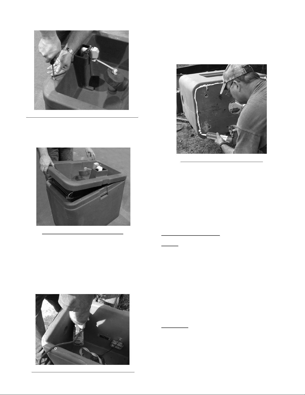
Next remove the four screws from the rim of the
basin, illustration 4.
Illustration 4 - Removing Screws From Top
You can now remove the basin with the heat pad
assembly by lifting up on the rim of the basin
opposite of the drain, illustration 5.
Following these marks drill four 3/8” dia. x 2”
deep holes in the concrete platform. Turn the
drinker on its side and apply caulking around the
bottom outer edge and center opening. Make
sure to apply enough caulking to seal any
irregularities between the drinker and the
platform, see Illustration # 7.
Illustration 7 - Caulking Bottom
Illustration 5 - Removing Basin
You will now have three pieces, the float cover
assembly, the basin assembly and the base
assembly.
If you are using expandable anchor bolts,
proceed as follows: Center the drinker base
assembly on the pad and transfer the mounting
hole locations to the pad, illustration 6.
Secure the drinker base to pad using four 3/8” x
4” expandable anchor bolts with 3/8” fender
washer (purchased locally),
While the basin is off, it is good time to install the
¾” hose barb connection to the riser pipe.
Reinstall the basin assembly to the base and
remove the side access door. You can leave the
float cover off until the water level is adjusted.
Electrical Connections
NOTE: Electrical connections should be made by
a qualified electrician and all local codes need to
be followed. The heating pad is 220 watt, 120
volt AC, 1.8 amp unit. It is thermostatically
controlled so it only operates when there is a
demand for heat. It is recommended that you
shut off the power to the drinker during warm
weather when heat is not required.
A 120 volts of AC power that is grounded and
contains Ground Fault Circuit Interruption (GFCI)
is required to operate this drinker. Normally, a 15
amp power supply is used to power the drinker.
CAUTION:
This drinker contains live electrical
components, disconnect the power before
servicing.
There are three connections and a ground that
are required to connect your drinker. These
connections are to be made with the three
Illustration 6 - Transfer & Drilling Holes
F-20406 10-3-05
supplied DRYCON wire nuts. These wire nuts
Page 4
are silicone filled and provide maximum
protection against moisture. They are a one time
use connector so, if reconnection is necessary
new wire nuts will need to be obtained. All
connections should be made inside the electrical
box.
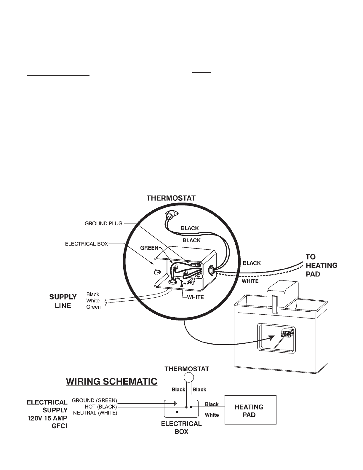
Ground Connection:
The green (ground) wire
from the supply line connects to the grounding
lug inside the electrical box. The wiring will be
easier if you hook up the ground wire first.
First Connection:
A black and a white come
from the heating pad. The white wire connects to
the White (neutral) wire of the supply line.
Second Connection:
The black wire from the
heating pad connects to either one of the two
black wires of the thermostat.
Refer to the illustration below for details and
schematic of this wiring connection.
Do not turn on the power until after the water
connections have been made and tested to
assure that there are no leaks.
N0TE:
The use of the riser pipe as the grounding
rod is not recommended. This is due to the
extensive use of plastic pipe on the farmsteads
and the unknown grounding properties of the
existing pipe on the site.
WARNING:
Compliance with the national electric
code (CSA in Canada) and local electrical codes
must be made and maintained when installing
the drinker. Failure to comply and maintain the
drinker to code could result in loss of livestock,
severe personal injury, or even death.
Third Connection:
The other black wire from the
thermostat connects to the black (hot) wire of the
supply line.
F-20407 10-3-05
Page 5
Water Hookup and Float Adjustment
When cutting the flex hose, leave a little extra
length to allow for movement of the platform
during cold weather. However, do not leave too
much length or the hose will kink and restrict the
water flow. Slide the hose over the barb and
secure it with the hose clamp. Make sure all
connections are tight.
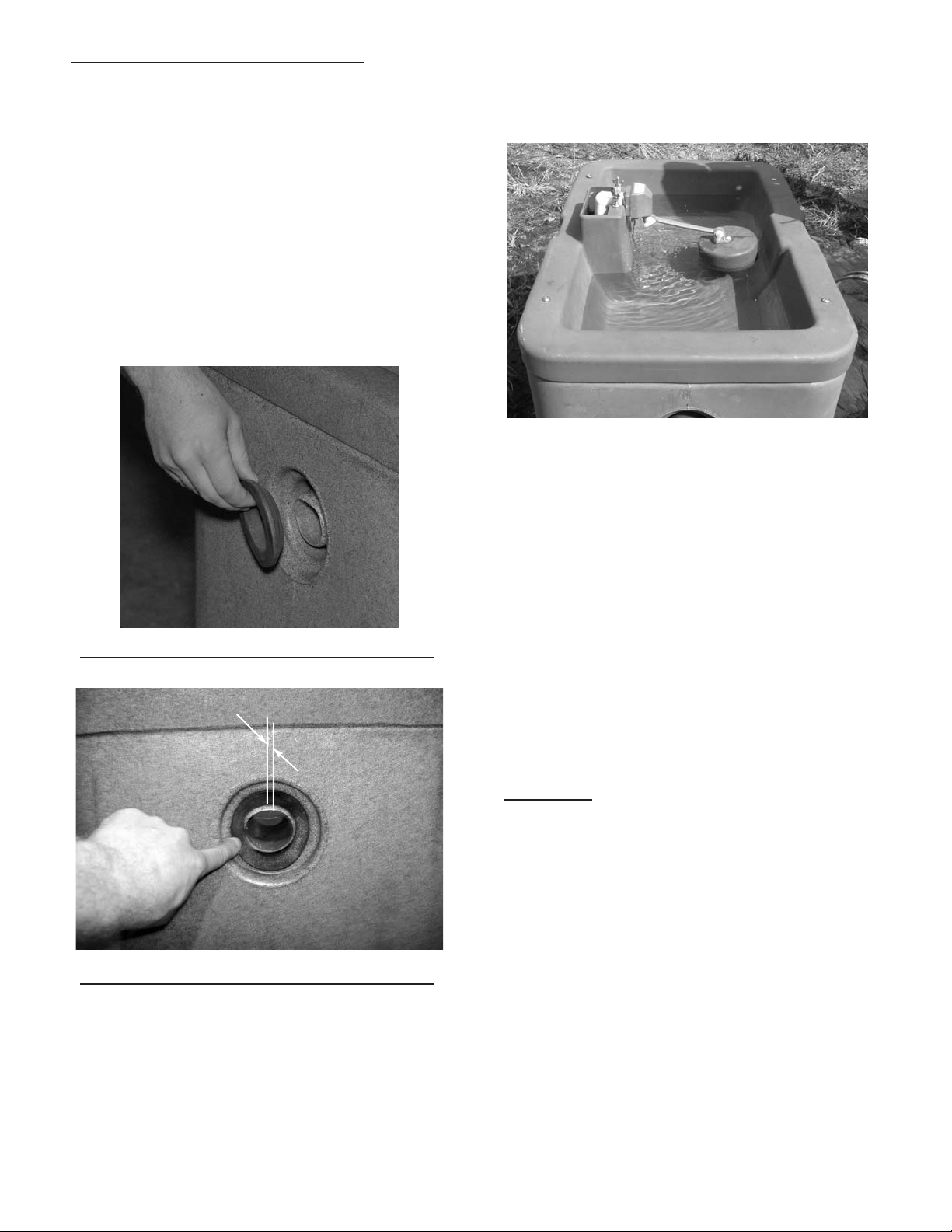
Insert the foam sealing ring coneside first from
the outside of the drinker. Push the edges of the
ring with finger so that the ring is in a quarter of
an inch past the rim. The drain plug is installed in
the end of the drain spout from the outside of the
drinker. See Illustrations #8 & 9).
Adjust the float by using the two thumb screws.
Set the float to maintain a water level in the
trough of 1" to 1½" below the top of the rim of the
trough. See illustration 10.
Illustration 10 - Setting Water Level
Check all connections for leaks and if none are
present the power can be turned on to the unit
and the access door installed.
Illustration 8 - Installing Foam Sealing Ring
1/4"
Illustration 9 - Foam Sealing Ring Installed
Note: Your drinker is equipped with a BL valve
that is easy to clean and adjust. If low water
pressure conditions exist and a higher flow rate is
desired, a larger inlet is available (3888247).
If you encounter problems after hooking up your
drinker, please refer to the trouble shooting chart
for information on possible solutions.
Warranties
All Behlen Country Electric Drinkers carry a
5 year limited warranty on the body and a 1 year
limited warranty on the valve and controls.
The water can now be turned on and the float
level set.
F-20408-1 Rev. 11-12-08 10-3-05
Page 6
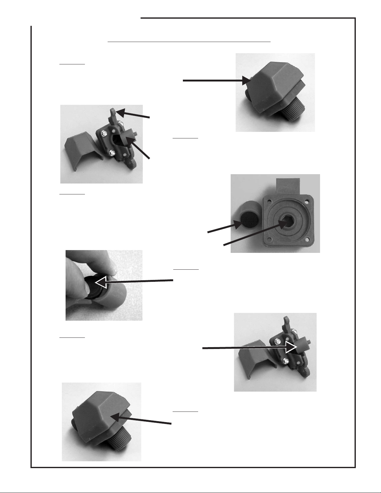
ASSEMBLY INSTRUCTIONS
Instructions for Cleaning the Valve
STEP 1:
Remove the packaging tape from around the top
of the valve.
STEP 3:
Lever
STEP 2:
Slip off the cover and lift the lever to remove the
plunger.
Plunger
Clean the rubber part of the plunger and opening
to the valve of any calcium or dirt buildup that
may be obstructing the normal operation of the
valve.
STEP 5:
Replace the plunger with the nipple facing you,
and the rubber facing the valve.
Rubber
Valve Opening
STEP 4:
If the rubber seal is grooved but still pliable (not
hard and brittle) you may flip it over and use
the backside of the seal.
STEP 6:
Replace the cover to complete the cleaning of
the valve.
F-20201 8-18-04
Page 7

Ice in Trough
TROUBLE SHOOTING CHART
For Behlen Country Electric Drinkers
• Check fuses or circuit breakers.
• Check to see if there are any gaps that allow cold air to enter the base of the
drinker.
- Make sure the fountain is sealed from wind between the concrete platform and
bottom of the drinker.
- Make sure there are no air leaks around the access door.
• Check to make sure that you have a full 120 volts at the drinker and that the 120
volts are maintained when the heater is on.
• Check the heating elements to make sure they are working and hot.
• Check that heater is wired properly.
• Check voltage after thermostat to fountain with and without electrical load (Note: to
close the thermostat to complete the circuit, hold a piece of ice in a plastic bag
next to sensing surface).
• Adjust thermostat to higher temperature by moving it further away from the heat
pad (make moves in 2” steps).
• Make sure supply line is properly installed.
Water Freezing
in the Valve or
Supply Line
Valve Won’t
Stop Dripping
or Shut Off
- Riser tube with supply line centered, and there is an air space between riser tube
and supply line.
- Horizontal supply line is at least 1' below frost line.
• Check for missing or damaged insulation.
• Check for air gaps against wind penetrations.
- Make sure the fountain is sealed from wind between the concrete platform and
bottom of the drinker.
- Make sure there are no leaks around the access door.
- Make sure that the latches are holding the float cover securely to drinker. If the
latches are loose, adjust spring tension on the latch and, if necessary, bend the
latch ends in vise thus enabling the latches to hold the cover tighter.
• Check the float adjustment. Check for waterlogged float, or float rubbing on side of
the valve compartment. Ensure that the float moves freely.
• Disassemble valve and check for sand or scale in valve rubber. Also check valve
orifice outlet for wear and damage. A screen or filter may be required with sandy or
scaly water. Please refer to the valve cleaning instructions supplied with your
drinker.
• Turn valve rubber over and re-assemble.
• Check for excessive water system pressure (greater than 55 psi). If needed,
change to our higher pressure APEX valve, or install a pressure regulator, available
at most plumbing shops.
• Check that the valve inlet is not plugged or supply hose is not kinked.
• Check system pressure from supply hose by installing a tee and a pressure gauge
Low Water Flow
F-20409 10-3-05
directly in front of the valve and then check pressure drop when valve is open. A
severe pressure drop indicates a restriction or undersized supply system.
• Check that shut off valves are fully open.
 Loading...