

Page 1

ASSEMBLY INSTRUCTIONS
Poly Electric and Non-Electric Drinkers
(Models PCPE, PCPI, PCSE, PCSI, PFL-C, PFL-H, PCHI, PCHE, XCPE)
THANK YOU FOR PURCHASING THIS PRODUCT
For questions about this product, or for parts inquiries, please contact our Customer Service Center listed below.
Before beginning, read instructions
thoroughly and inspect parts listing to insure
that all parts have been included.
Preparation of Location:
Install drinker on a 4" (minimum) thick
concrete base, slightly raised for better
drainage. Before pouring concrete, have the
water and electricity connected up through a
4" or larger tile for final connections to the
drinker. Be sure the edge of the tile is
slightly raised above the concrete (approx.
1-1/2") so that water drainage does not go
into the open tile. The tile must be left open
to give access to warmer air below the frost
line, thus preventing the riser from freezing.
Be sure the riser pipe does not touch the
sides of the tile. Note: The concrete pad
should be at least 4" larger than the poly
CPE drinkers on all sides.
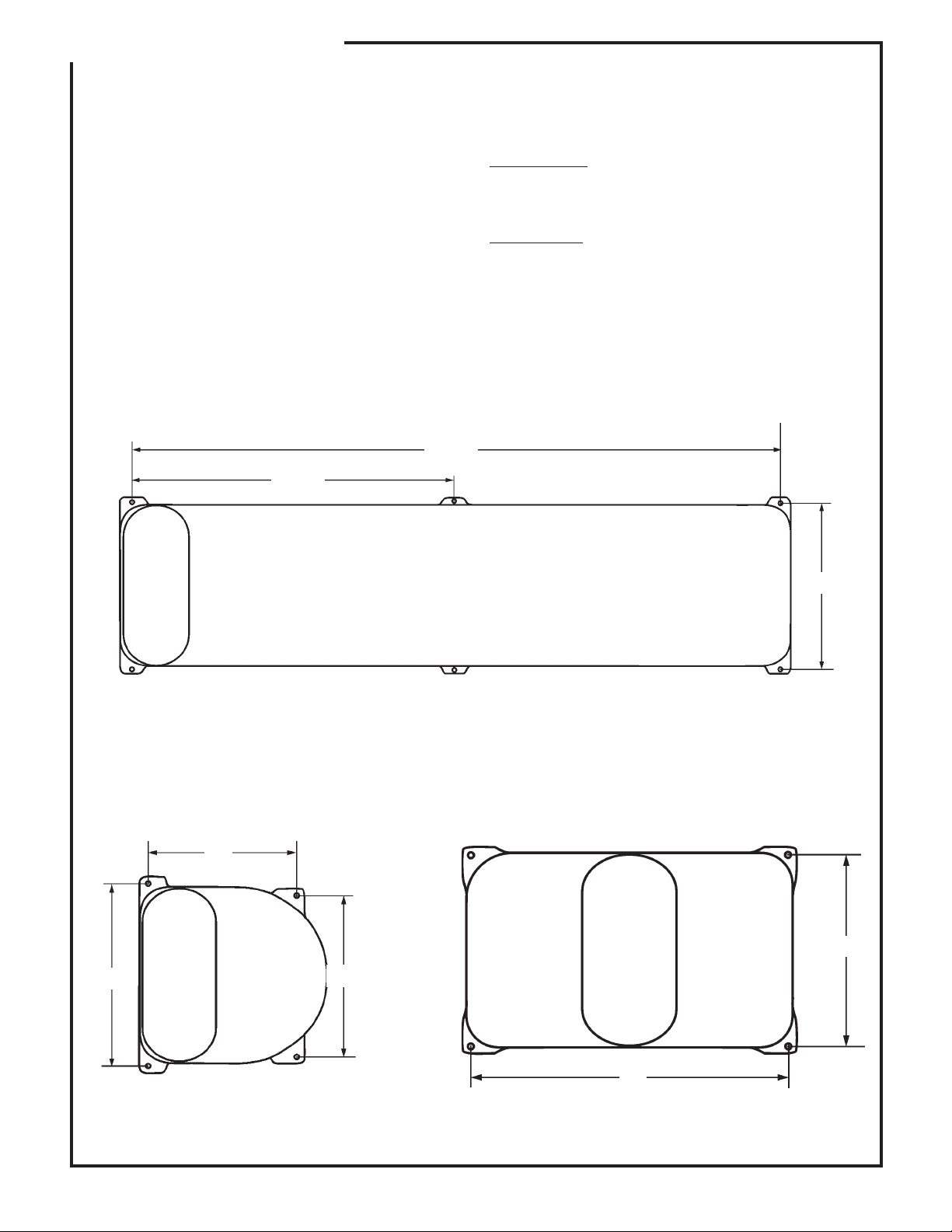
Model
PCPE 25" x 36" 27.5" 16.5"
PCPI 25" x 36" 27.5" 16.5"
PCSE 25" x 36" 27.5" 16.5"
PCSI 25" x 36" 27.5" 16.5"
PFL-C 28" x 92" - PFL-H 28" x 92" - PCHE 30" x 30" - PCHI 30" x 30" - XCPE 40” x 36” 33.0” 28.0”
Place the drinker in the desired position and
drill 3/8" dia. x 1-1/2" (min.) deep holes, in
the concrete using the molded-in hold down
tabs at the base of the drinker as a guide.
Cut the proper size hole in the 1" insulation
board to fit over the riser tile. It is important
to use this insulation board to help insulate
and seal the bottom of the drinker. Enough
1" x 3/8" weather strip is included with your
drinker to seal the bottom of the drinker to
the concrete base and also to seal the float
Min. Pad Size A B
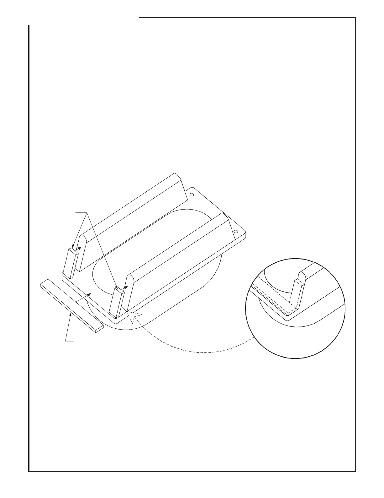
cover to the drinker. Put weatherstrip on the
bottom of the drinker where it contacts with
the concrete base. If there are any gaps
bigger than 3/8", two layers of weatherstrip
can be put together to fill the gap. Please refer
to the sketch in these sheets for proper
placement of weatherstrip on the float cover.
Secure the drinker using 3/8" x 1-7/8"
expandable anchor bolts (purchased locally).
Water Line:
For connection of the drinker to the riser pipe,
a high pressure ¾" I.D. hose is supplied with
the drinker. A shut off valve which is easily
accessible should be used at each drinker. If
the drinker is to be shut down for the winter, a
Shut-off Kit (Item No. 54130168) that drains
the riser pipe to prevent freezing is available.
The supply line should be flushed before
drinker is connected. N0TE: Your drinker is
equipped with a BL valve that is easy to clean
and adjust. If low water pressure conditions
exist and a higher flow rate is desired, a larger
inlet is available (54300968) to increase the
flow. (For hookup instructions see Technical
Information 70131).
Electrical Connections
(for PCPE, PCSE, XCPE, PFL-H & PCHE
models only):
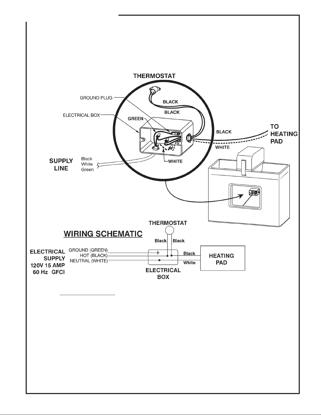
NOTE: Electrical connections should be made
by a qualified electrician. The black wire from
the power supply must be connected to the
thermostat and the white wire from the supply
connected to the white wire on the heating
pad. The grounding wire from the supply
must be connected to the terminal in the
electrical box of the drinker.
The unit must be properly grounded to the
supply box and fused properly. The fuse size
is indicated on the red ground instruction tag.
CUSTOMER SERVICE CENTER
PO Box 569
Columbus, NE
68602-0569
F-19906-8 TECHNICAL INFORMATION 70112 Rev. 2-18-09 8-15-02
Ph: 1-800-447-2751
Fax: (402) 563-7447
www.behlencountry.com
Page 2
ASSEMBLY INSTRUCTIONS
Units should be wired according to the
ASAE farm wiring recommendations except
where different from local regulations.
N0TE: The use of the riser pipe as the
grounding rod is not recommended. This is
due to the extensive use of plastic pipe on
the farmsteads and the unknown grounding
properties of existing pipe on the site.
WARNING: Compliance with the national
electric code (CSA in Canada) and local
electrical codes must be made and
maintained when installing the drinker.
DRINKER MOUNTING LOCATION FOR PFL-H
40-1/2”
Failure to comply and maintain the drinker to
code could result in loss of livestock, severe
personal injury, or even death.
Adjustment:
Adjust the float to maintain a water level in the
trough of 1" to 1½" below the top of the trough.
Warranties:
All Behlen Country Electric Drinkers carry a 5
year limited warranty on the body and a 1 year
limited warranty on valves and controls.
81”
DRINKER MOUNTING LOCATION
FOR PCHE AND PCHI
16”
21”
18-1/2”
21”
DRINKER MOUNTING LOCATION FOR
PCPE, PCPI, PCSE, PCSI, and XCPE
B
A
F-19907-3 Rev. 1-25-08 8-15-02
Page 3
ASSEMBLY INSTRUCTIONS
Applying Weatherstrip to the Float Cover
2.5 ft. Of Weatherstrip #2048041
Cut into (4) 3” strips and (2) 8” strips
Cut 3” long
Cut 8” long
Peel off backing of self-adhering weatherstrips and
apply to both sides of Inspection Cover.
Install weatherstrip seal
to corners of Inspection
Cover as shown.
F-20070 2-2-04
Page 4
ASSEMBLY INSTRUCTIONS
VIEW INSIDE
CAVITY OF DRINKER
IMPORTANT NOTE:
Voltage must be grounded and contain Ground Fault
Circuit Interruption (GFCI). Contains live electrical components, disconnect
power before servicing.
F-19909-4 Rev. 3-17-08 8-15-02
Page 5
ASSEMBLY INSTRUCTIONS
Instructions How To Assemble The Float And Arm To
The Franklin BL Valve And How To Adjust The Valve
The Franklin Valve is already attached to the drinker. The float and arm assembly is with the
hardware kit. They are packaged separately to prevent undue wear to the valve caused by the
arm bouncing up and down during shipping.
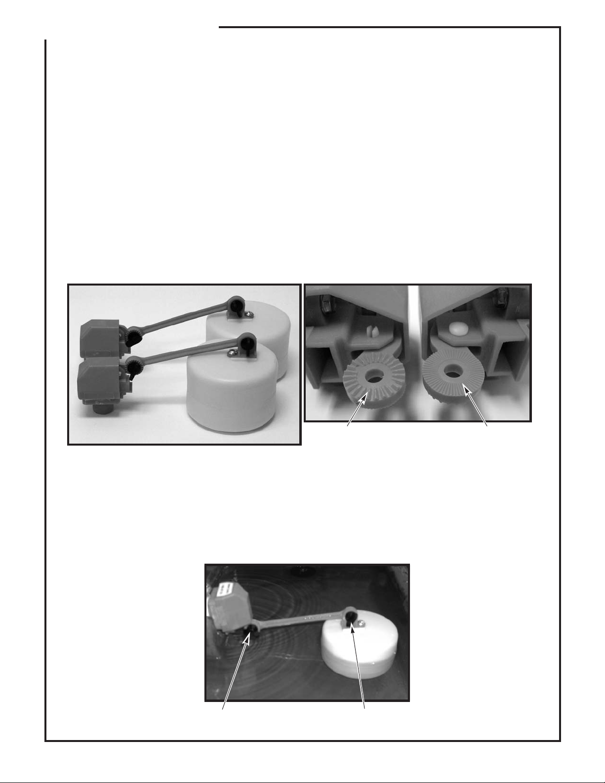
The float and arm are attached to the valve by a thumb screw. The float can be positioned
either closer or further away from the valve (see photo below left for the two float positions).
Further away increases the shut off force of the valve. However depending upon which drinker
is being used, the closer position may be required to maintain proper clearance for the float to
the side of the drinker. A clearance of at least 1/2" should be maintained to ensure smooth
operation of the valve.
When attaching the float arm to the valve, be sure to attach the arm to the correct side of the
valve. The grooves on the valve and float arm must match. Please note that the valve has
coarse grooves on one side and fine grooves on the other. The fine grooved side is used with
the float arm (see below right for details).
Coarse Fine
To adjust the water level in the drinker, loosen the thumb screws and position the float and arm
so that the valve is turned off when the water is at the desired level (see photo below). It may
take a couple of adjustments to get the correct level (1-1½" below the top of the trough). To
speed the adjustment process, remove the drain plug and drain a little water out so that the
valve turns on. Put the drain plug back and let water fill until the valve shuts off. If the level is
not correct, repeat the process until the correct level is obtained and then replace the float
cover. Your drinker is now ready for use.
Adjust Adjust
F-20569 3-17-08
Page 6

Ice in Trough
Water Freezing
in the Valve or
Supply Line
TROUBLE SHOOTING CHART
For Behlen Country Electric Drinkers
• Check fuses or circuit breakers.
• Check to see if there are any gaps that allow cold air to enter the base of the
drinker.
- Make sure the fountain is sealed from wind between the concrete platform and
bottom of the drinker.
- Make sure there are no air leaks around the access door.
• Check to make sure that you have a full 120 volts at the drinker and that the 120
volts are maintained when the heater is on.
• Check the heating element to make sure it is working and hot.
• Check that heater is wired properly.
• Check voltage after thermostat to fountain with and without electrical load (Note: to
close the thermostat to complete the circuit, hold a piece of ice in a plastic bag
next to sensing surface).
• Adjust thermostat to higher temperature by moving it further away from the heat
pad (make moves in 2” steps).
• Make sure supply line is properly installed.
- Riser tube with supply line centered, and there is an air space between riser tube
and supply line.
- Horizontal supply line is at least 1' below frost line.
• Check for missing or damaged insulation.
• Check for air gaps against wind penetrations.
- Make sure the fountain is sealed from wind between the concrete platform and
bottom of the drinker.
- Make sure there are no leaks around the access door.
- Make sure that the latches are holding the float cover securely to drinker. If the
latches are loose, adjust spring tension on the latch and, if necessary, bend the
latch ends in vise thus enabling the latches to hold the cover tighter.
• Check the float adjustment. Check for waterlogged float, or float rubbing on side of
the valve compartment. Ensure that the float moves freely.
• Disassemble valve and check for sand or scale in valve rubber. Also check valve
Valve Won’t
Stop Dripping
or Shut Off
Low Water Flow
F-19908-1 8-10-06
orifice outlet for wear and damage. A screen or filter may be required with sandy or
scaly water. Please refer to the valve cleaning instructions supplied with your
drinker.
• Turn valve rubber over and re-assemble.
• Check for excessive water system pressure (greater than 55 psi). If needed, install
a pressure regulator, available at most plumbing shops.
• Check that the valve inlet is not plugged or supply hose is not kinked.
• Check system pressure from supply hose by installing a tee and a pressure gauge
directly in front of the valve and then check pressure drop when valve is open. A
severe pressure drop indicates a restriction or undersized supply system.
• Check that shut off valves are fully open.
 Loading...