

Page 1

Multifunction Installation Tester
ProInstall-75
User Manual
Page 2

Page 3

Multifunction Installation
Tester
ProInstall-75
User Manual
1/2017, Rev A
©2017 Beha-Amprobe.
All rights reserved.
English
Page 4

Limited Warranty and Limitation of Liability
Your Beha-Amprobe product will be free from defects in material and workmanship for
two years from the date of purchase unless local laws require otherwise. This warranty does
not cover fuses, disposable batteries or damage from accident, neglect, misuse, alteration,
contamination, or abnormal conditions of operation or handling. Resellers are not authorized
to extend any other warranty on the behalf of Beha-Amprobe. To obtain service during the
warranty period, return the product with proof of purchase to an authorized Beha-Amprobe
Service Center or to an Beha-Amprobe dealer or distributor. See Repair Section for details.
THIS WARRANTY IS YOUR ONLY REMEDY. ALL OTHER WARRANTIES - WHETHER EXPRESS,
IMPLIED OR STATUTORY - INCLUDING IMPLIED WARRANTIES OF FITNESS FOR A PARTICULAR
PURPOSE OR MERCHANTABILITY, ARE HEREBY DISCLAIMED. MANUFACTURER SHALL NOT BE
LIABLE FOR ANY SPECIAL, INDIRECT, INCIDENTAL OR CONSEQUENTIAL DAMAGES OR LOSSES,
ARISING FROM ANY CAUSE OR THEORY. Since some states or countries do not allow the
exclusion or limitation of an implied warranty or of incidental or consequential damages, this
limitation of liability may not apply to you.
Repair
All Beha-Amprobe tools returned for warranty or non-warranty repair or for calibration
should be accompanied by the following: your name, company’s name, address, telephone
number, and proof of purchase. Additionally, please include a brief description of the
problem or the service requested and include the test leads with the meter. Non-warranty
repair or replacement charges should be remitted in the form of a check, a money order,
credit card with expiration date, or a purchase order made payable to Beha-Amprobe.
In-warranty Repairs and Replacement – All Countries
Please read the warranty statement and check your battery before requesting repair.
During the warranty period, any defective test tool can be returned to your Beha-Amprobe
distributor for an exchange for the same or like product. Please check the “Where to Buy”
section on beha-amprobe.com for a list of distributors near you.
Non-warranty Repairs and Replacement – Europe
European non-warranty units can be replaced by your Beha-Amprobe distributor for a
nominal charge. Please check the “Where to Buy” section on beha-amprobe.com for a list of
distributors near you.
Beha-Amprobe Germany Beha-Amprobe United Kingdom
In den Engematten 14 52 Hurricane Way
79286 Glottertal Norwich
+49 (0) 7684 8009 - 0 Norfolk, NR6 6JB
beha-amprobe.de +44 (0) 1603 25 6662
beha-amprobe.com
Beha-Amprobe Headquarters
Science Park
Eindhoven 5110
5692 EC Son, The Netherlands
+31 (0)40 267 51 00
beha-amprobe.com
Page 5

1
ProInstall-75
CONTENTS
INTRODUCTION ...........................................................................................................3
SYMBOLS .....................................................................................................................3
SAFETY INFORMATION ...............................................................................................4
UNPACKING THE TESTER ............................................................................................5
OPERATING THE TESTER .............................................................................................5
Using the Rotary Switch ........................................................................................................ 5
Understanding the Pushbuttons ........................................................................................... 5
Understanding the Display ................................................................................................... 7
Input Terminals ...................................................................................................................... 9
Error Codes ............................................................................................................................. 9
Power-On Options ................................................................................................................. 10
MAKING MEASUREMENTS .........................................................................................11
Measuring Volts and Frequency ........................................................................................... 11
Measuring Insulation Resistance .......................................................................................... 11
Measuring Continuity ........................................................................................................... 12
Measuring Loop/Line Impedance ......................................................................................... 12
Loop impedance (line to protective earth L-PE) ........................................................... 13
Earth resistance testing by loop method ....................................................................... 14
Line impedance ............................................................................................................... 15
Measuring RCD Tripping Time .............................................................................................. 16
Measuring RCD Tripping Current ......................................................................................... 18
RCD Testing in IT Systems ...................................................................................................... 20
Testing Phase Sequence ........................................................................................................ 20
MAINTAINING THE TESTER .........................................................................................21
Cleaning ................................................................................................................................. 21
Testing and Replacing the Batteries ..................................................................................... 21
Testing the Fuse ..................................................................................................................... 22
DETAILED SPECIFICATIONS .........................................................................................23
Features .................................................................................................................................. 23
General Specifications ........................................................................................................... 24
ELECTRICAL MEASUREMENT SPECIFICATIONS ..........................................................25
Insulation Resistance (R
ISO
) ................................................................................................... 25
Page 6

2
Continuity (R
LO
) ..................................................................................................................... 26
Loop Tests (Z
I
) ........................................................................................................................ 26
RCD/FI Tests (
PT, IPN) ........................................................................................................... 27
AC Voltage Measurement (V) ............................................................................................... 28
Continuity Testing (R
LO
) ........................................................................................................ 28
Insulation Resistance Measurement (R
ISO
) ........................................................................... 28
No Trip and Hi Current Modes RCD/FI .................................................................................. 29
Prospective Short Circuit Current Test (PSC/I
K
)
Prospective Earth Fault Current (PEFC) ................................................................................ 29
RCD TESTING ...............................................................................................................30
RCD Types Tested ................................................................................................................... 30
Test Signals ............................................................................................................................. 30
RCD Types Tested (
PT) .......................................................................................................... 30
Maximum Trip Time ............................................................................................................... 31
RCD/FI-Tripping Current Measurement/Ramp Test (I
PN ) .................................................. 31
Phase Sequence Indication .................................................................................................... 31
MAINS WIRING TEST ...................................................................................................32
OPERATING RANGES AND UNCERTAINTIES PER EN 61557 .......................................32
Page 7
3
INTRODUCTION
The Beha-Amprobe Model ProInstall-75 is a battery powered multifunction installation tester.
This tester is designed to measure and test the following:
• Voltage and Frequency
• Insulation Resistance (EN61557-2)
• Continuity (EN61557-4)
• Loop/Line Resistance (EN61557-3)
• Residual Current Devices (RCD) Tripping Time (EN61557-6)
• RCD Tripping Current (EN61557-6)
• Phase Sequence (EN61557-7)
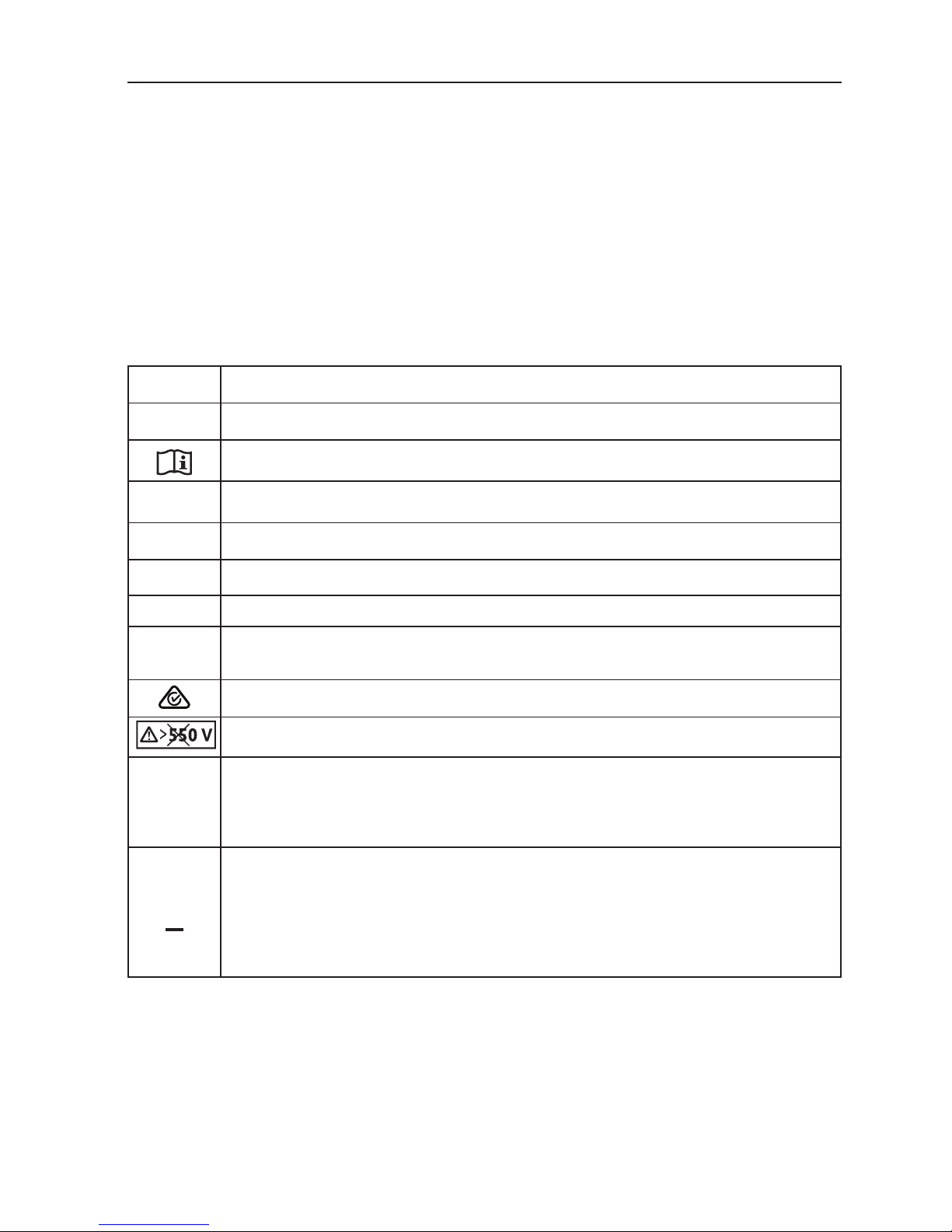
SYMBOLS
Caution! Risk of electric shock.
W
Caution! Refer to the explanation in this manual.
Consult user documentation.
T
Double insulated (Class II) equipment
J
Earth (Ground).
I
Fuse.
M
Battery.
P
Conforms to requirements of European Union and European Free Trade
Association.
Conforms to relevant Australian standards.
Do not use in distribution systems with voltages higher than 550 V.
CAT III /
CAT IV
CAT III Testers are designed to protect against transients in fixed equipment
installations at the distribution level; CAT IV Testers are designed to protect
against transients from the primary supply level (overhead or underground
utility service).
=
This product complies with the WEEE Directive marking requirements. The
affixed label indicates that you must not discard this electrical/electronic
product in domestic household waste. Product Category: With reference to
the equipment types in the WEEE Directive Annex I, this product is classed as
category 9 “Monitoring and Control Instrumentation” product. Do not dispose of
this product as unsorted municipal waste.
Page 8

4
SAFETY INFORMATION
A Warning identifies hazardous conditions and actions that could cause bodily harm or death.
A Caution identifies conditions and actions that could damage the installation tester or
cause permanent loss of data.
WWarnings: Read Before Using
To prevent possible electrical shock, fire, or personal injury:
• Use the product only as specified, or the protection supplied by the product can be
compromised.
• Do not use the product around explosive gas, vapor or in damp or wet environments.
• Do not use test leads if they are damaged. Examine the test leads for damaged
insulation, exposed metal, or if the wear indicator shows. Check test lead continuity.
• Use only probes, test leads, and adapters supplied with the product.
• Measure a known voltage first to make sure that the product operates correctly.
• The battery door must be closed and locked before you operate the Product.
• Examine the case before you use the Product. Look for cracks or missing plastic.
Carefully look at the insulation around the terminals.
• Be sure that the battery polarity is correct to prevent battery leakage.
• Repair the Product before use if the battery leaks.
• Do not operate the Product with covers removed or the case open. Hazardous voltage
exposure is possible.
• Do not apply more than the rated voltage between the terminals or between each
terminal and earth ground.
• Do not use the product if it is damaged.
• Have an approved technician repair the product.
• Do not apply more than the rated voltage between the terminals or between each
terminal and earth ground.
• Remove all probes, test leads, and accessories before opening the battery door and the
product case.
• Do not operate the product with covers removed or the case open. Hazardous voltage
exposure is possible.
• Use caution when working with voltages above 30 V ac rms, 42 V ac peak, or 60 V dc.
• Use only specified replacement fuses.
• Use the correct terminals, function, and range for measurements.
• Keep fingers behind the finger guards on the probes.
• Connect the common test lead before the live test lead and remove the live test lead
before the common test lead.
• Replace the batteries when the low battery indicator shows to prevent incorrect
measurements.
• Use only specified replacement parts.
• Do not use the tester in distribution systems with voltages higher than 550 V.
• Comply with local and national safety codes. Use personal protective equipment
(approved rubber gloves, face protection, and flame-resistant clothes) to prevent shock
and arc blast injury where hazardous live conductors are exposed.
Page 9
5
UNPACKING AND INSPECTION
Your shipping carton should include:
• ProInstall-75
• Test lead set
• ProInstall-TL-UK (LC38 AMP-MFT, mains test cord)
• Alligator clips
• Test probe
• ProInstall-TL-KIT (Remote test probe and probe tips)
• ProInstall-CC (Soft case with carrying strap)
• TL-75 ( Fused test probe, red/blue/green with lantern spring, cap and tip cover)
• Zero-Adapter
• Statement of calibration
• Batteries
• Quick reference guide
• Carry strap for neck/waist
• CD-ROM (User manual)
If any of the items are damaged or missing, return the complete package to the place of
purchase for an exchange.
OPERATING THE TESTER
Using the Rotary Switch
Use the rotary switch to select the type of test you want to perform.
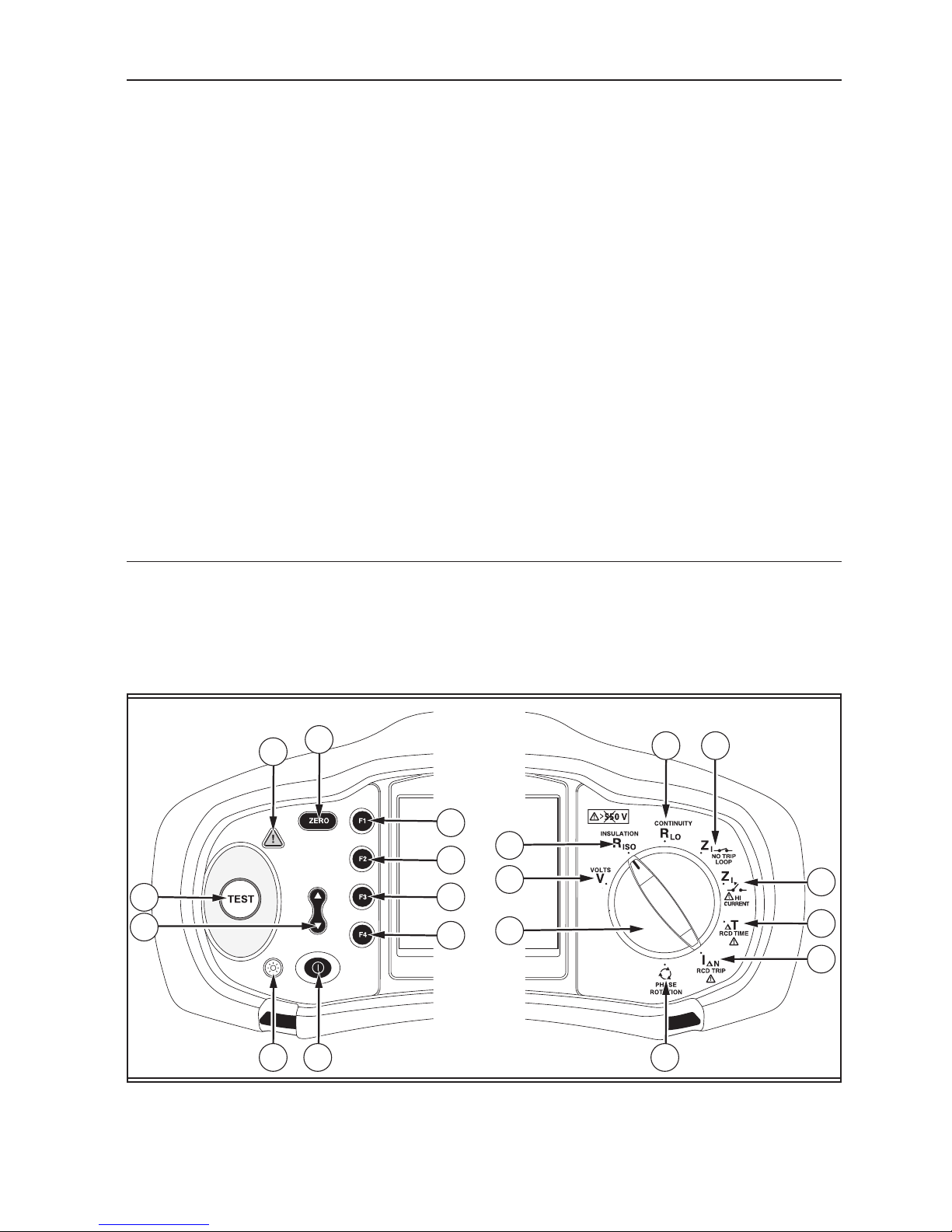
Understanding the Pushbuttons
Use the pushbuttons to control operation of the tester, select test results for viewing, and
scroll through selected test results.
19
12
11
7
8
9
10
2
1
5 6 18
3
4
13 14
15
16
17
Page 10
6
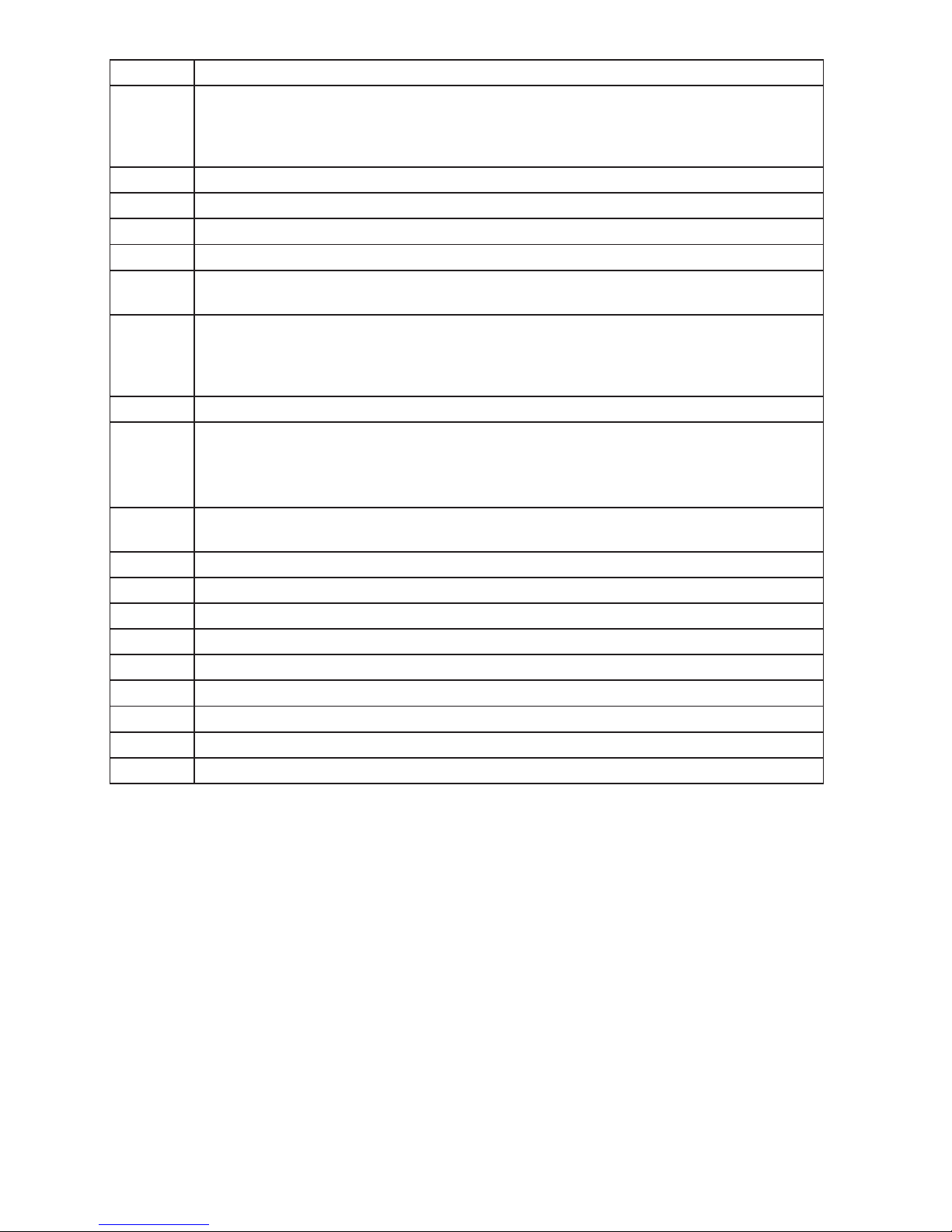
Number Measurement Function
1
Starts the selected test. The TEST key is surrounded by a “touch pad”. The touch
pad measures the potential between the operator and the tester’s PE terminal.
If you exceed a 100 V threshold, the
W symbol above the touch pad is illuminated.
2 Set RCD variable trip current.
3 Illuminates when > 100 V is detected on the touch pad.
4 Zero the test lead resistance offset.
5 Turns the backlight on and off.
6
Turns the tester on and off. The tester will also shut off automatically if there is
no activity for 10 minutes.
7
• Loop input select (L-N, L-PE).
• Voltage input select (L-N, L-PE, N-PE).
• Insulation test: (L-N, L-PE, N-PE)
• RCD current rating (10, 30, 100, 300, 500, 1000 mA or VAR).
8 RCD Current multiplier (x1/2, x1, x5, AUTO).
9
• Select RCD: Type AC (sinusoidal), Type AC Selective, Type A (half-wave), Type A
Selective.
• Battery test.
• Loop No Trip R
E
/ I
K
10
• RCD test polarity (0, 180 degrees).
• Insulation test voltage (250, 500, or 1000 V).
11 Volts.
12 Insulation resistance.
13 Continuity.
14 Loop impedance — No trip mode.
15 Loop impedance — Hi current trip mode.
16 RCD tripping time.
17 RCD tripping level.
18 Phase rotation.
19 Rotary switch.
Page 11
7
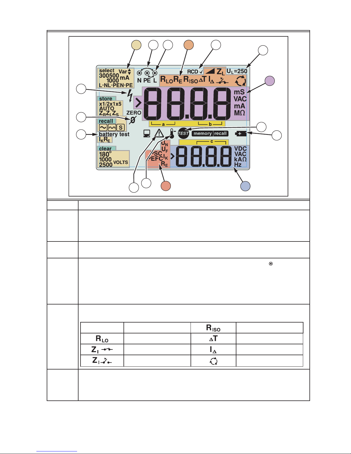
Understanding the Display
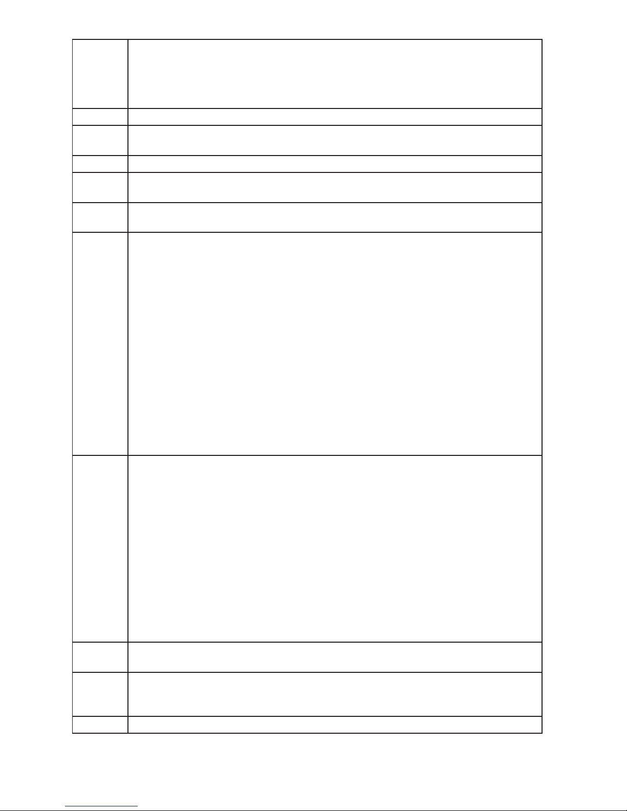
22
24
25
23
21
20
26
27
33
35
34
30
29
28
32
31
Number Description
20
Configuration options. Settings you can make within the measurement
functions. For example, in the RCD Tripping Time function (
PT) you can press
F2 to multiply the test current by x1/2, x1, x5 and you can press F3 to select the
type of RCD you are testing.
21
Arrows above or below the terminal indicator symbol indicate reversed polarity.
Check the connection or check the wiring to correct.
22
Terminal indicator symbol. A terminal indicator symbol with a dot
in the
center indicates the terminal is used for the selected function. The terminals
are:
• L (Line)
• PE (Protective Earth)
• N (Neutral)
23
Indicates the selected rotary switch setting. The measurement value in the
primary display also corresponds to the switch setting. Rotary switch settings are:
V
Volts
Insulation
Continuity RCD trip time
Loop no trip RCD trip current
Loop hi current trip Phase Rotation
24
Indicates that the measured trip current (trip current test) or the measured trip
time (trip time test) is according to the appropriate RCD standard and the fault
voltage is below the selected limit. For more information, see Maximum Trip
Time Table in the Specifications section of this manual.
Page 12
8
25
Indicates the preset fault voltage limit. The default setting is 50 V. Some
locations require the fault voltage be set to 25 V, as specified by local electrical
codes. Press F4 when you turn on the tester to toggle the fault voltage
between 25 V and 50 V. The value you set will appear on the display and will be
saved when you turn the tester off.
26 Primary display and measurement units.
27
Low battery icon. See “Testing and Replacing the Batteries” section for
additional information on batteries and power management.
28 Appears when you press the Test button. Disappears when the test is completed.
29
Appears when the instrument is overheated. The Loop test and RCD functions
are inhibited when the instrument is overheated.
30
Appears when an error occurs. Testing is disabled. See “Error Codes” on page 9
for a listing and explanation of possible error codes.
31
Name of the secondary measurement function.
U
N
Test voltage for insulation test.
U
F
Fault voltage. Measures neutral to earth.
PSC
Prospective Short Circuit. Calculated from measured voltage and impedance
when reading line to neutral.
PEFC
Prospective Earth Fault Current. Calculated from voltage and loop impedance
which is measured line to protective earth.
I
K
In combination with the PSC or PEFC symbol, indicates a short circuit current.
R
E
Earth resistance.
32
Secondary display and measurement units. Some tests will return more than
one result or return a computed value based on the test result. This will occur
with:
• Volts
Secondary display shows line frequency.
• Insulation tests
Secondary display shows actual test voltage.
• Loop/line impedance
Secondary display shows PEFC (Prospective Earth Fault Current) or R
E
PSC
(Prospective Short Circuit Current).
• RCD switching time
Secondary display shows UF fault voltage.
• RCD tripping current
Secondary display shows UF fault voltage.
33
Appears only in Volts. For more information see “Testing and Replacing the
Batteries” Section.
34
Appears when you press the button to zero the leads. After the zeroing
operation, the icon stays illuminated indicating that zeroing has been
performed. Only used when performing continuity or loop testing.
35 Potential danger. Appears when measuring or sourcing high voltages.
Page 13
9
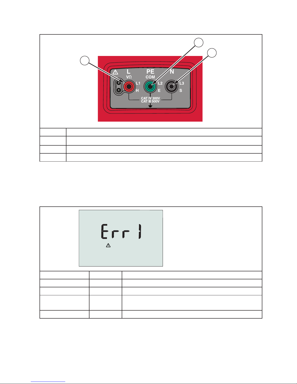
Input Terminals
Use the rotary switch to select the type of test you want to perform.
36
37
38
Number Description
36
L (Line)
37 PE (Protective Earth)
38 N (Neutral)
Error Codes
Various error conditions are detected by the tester and are indicated with the W icon,
“Err”, and an error number on the primary display. See table below. These error conditions
disable testing and, if necessary, stop a running test.
Figure 1. Error Display
Error Condition Code Solution
Self-test Fails 1 Return the tester to your distributor or Beha-Amprobe.
Over-temp 2 Wait while the tester cools down.
Fault Voltage 4
Check the installation, in particular, the voltage
between N and PE.
Excessive Noise 5 Switch off all appliances (Loop, RCD measurements)
Page 14
10
Power-On Options
To select a power-on option, press and the function key simultaneously and then release
the button. Power-on options are retained when the tester is turned OFF. See Table below.
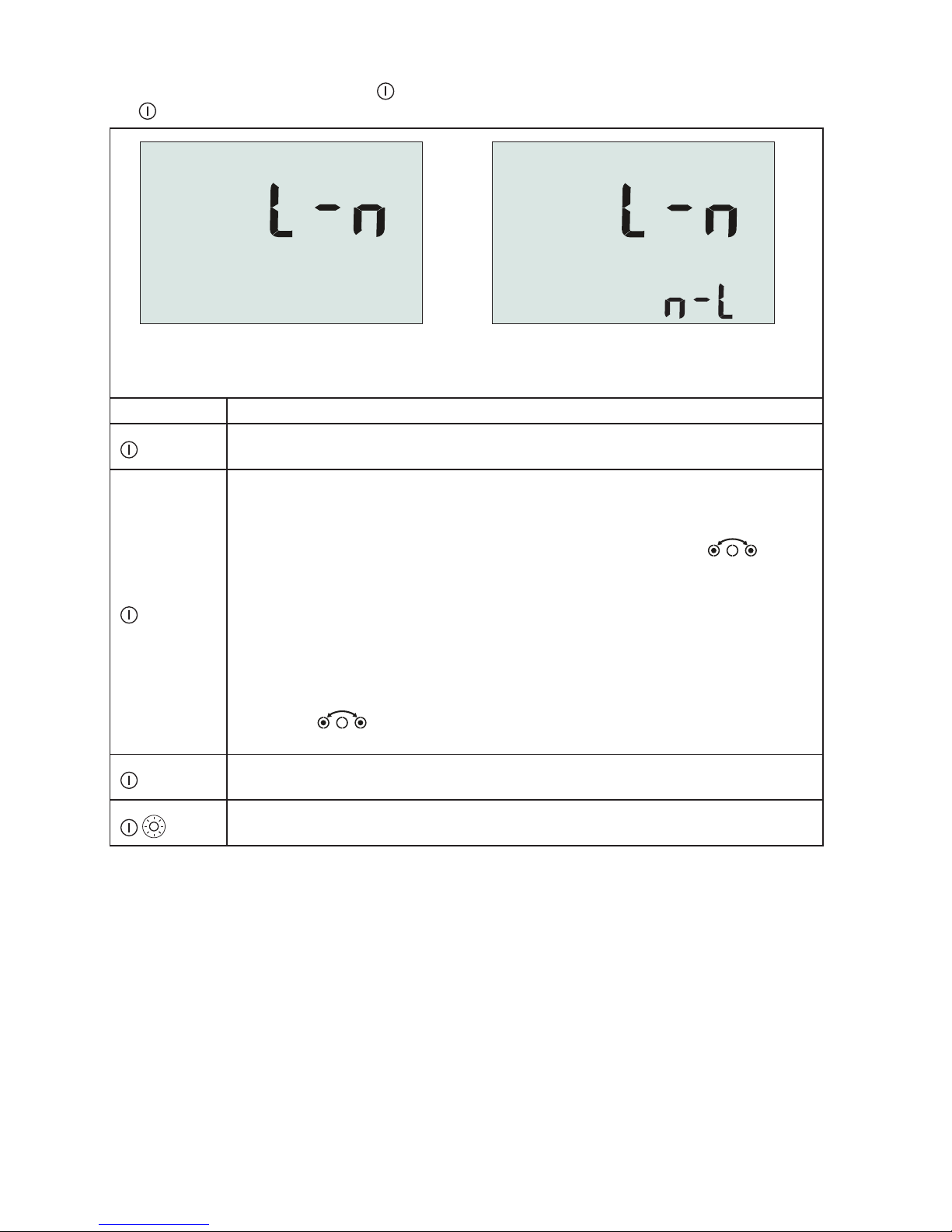
UK - Mode Selected Automatic Lead
Swapping Mode Selected
Figure 2. Lead Swapping Modes
Keys Power-on Options
Loop/Line Impedance IK limit. Toggles the IK limit between 10 kA and 50 kA.
The default is 10 kA.
Line and Neutral Swap mode. Two modes of operation are available. You
can configure the tester to operate in L-n mode or L-n n-L mode,
• In L-n mode, the L and N phase conductors must NEVER be reversed.
This is a requirement in some regions including the UK. The
icon
appears on the display indicating that the system L and N conductors are
swapped and testing is inhibited. Investigate and rectify the cause of this
system fault before proceeding. L-n mode also changes the RCD x1/2 trip
time duration to 2 seconds as required in the UK.
• In L-n n-L mode, the unit allows the L and N phase conductors to be
swapped and testing will continue.
Note: In locations where polarized plugs and outlets are used, a swapped
lead icon (
) may indicate that the outlet was wired incorrectly.
Correct this problem before proceeding with any testing.
Fault voltage limit. Toggles the fault voltage between 25 V and 50 V. The
default is 50 V.
Continuity beeper toggle. Toggles the continuity beeper on and off. The
default is on.
Page 15
11
MAKING MEASUREMENTS
Measuring Volts and Frequency
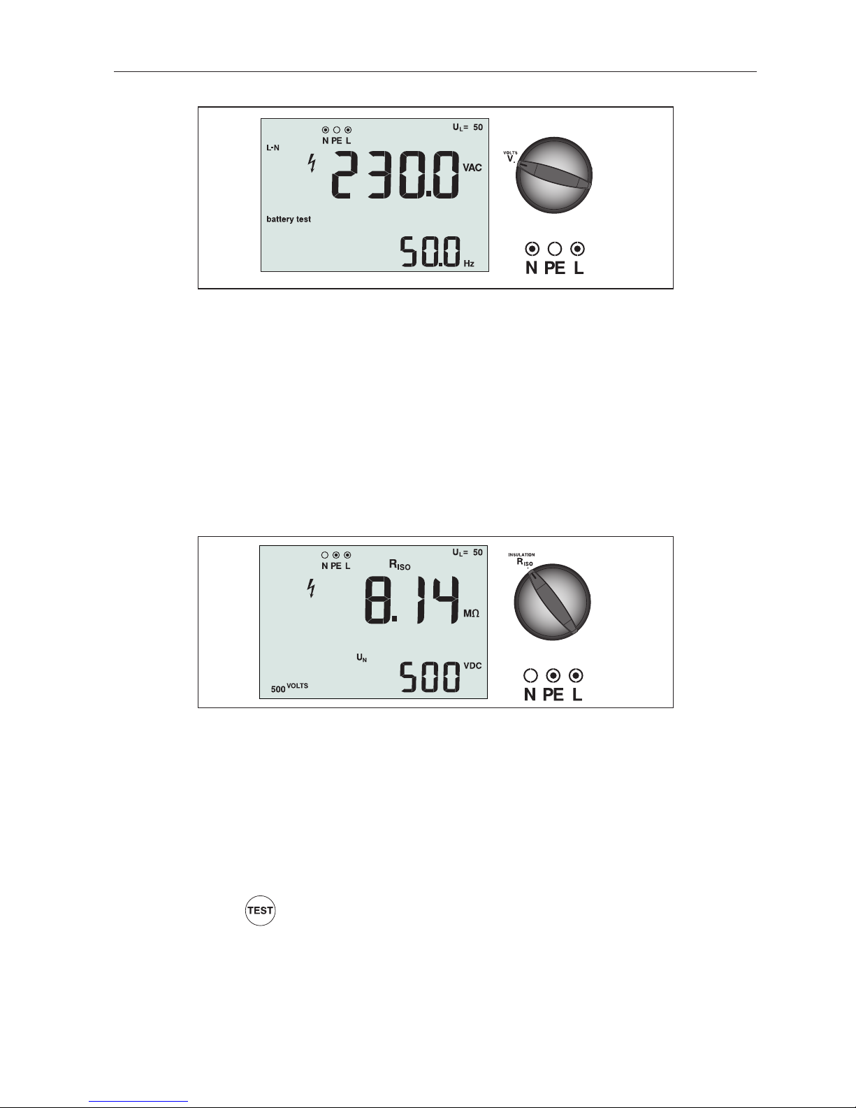
Figure 3. Volts Display/Switch and Terminal Settings
To measure voltage and frequency:
1. Turn the rotary switch to the V position.
2. Use two (red and blue) terminals for this test. You can use test leads or mains cord when
measuring AC voltage.
• The primary (upper) display shows the AC voltage. The tester reads AC voltage to 500 V.
Press F1 to toggle the voltage reading between L-PE, L-N, and N-PE.
• The secondary (lower) display shows mains frequency.
Measuring Insulation Resistance
Figure 4. Insulation Resistance Display/Switch and Terminal Settings
WWarning
To avoid electric shock, measurements should only be performed on de-energized circuits.
To measure insulation resistance:
1. Turn the rotary switch to the R
ISO
position.
2. Use the L and PE (red and green) terminals for this test.
3. Use the F4 to select the test voltage. Most insulation testing is performed at 500 V, but
observe local test requirements.
4. Press and hold
until the reading settles.
Note: Testing is inhibited if voltage is detected in the line.
• The primary (upper) display shows the insulation resistance.
• The secondary (lower) display shows the actual test voltage.
Note: For normal insulation with high resistance, the actual test voltage (UN) should
always be equal to or higher than the programmed voltage. If insulation resistance is
bad, the test voltage is automatically reduced to limit the test current to safe ranges.
Page 16
12
Measuring Continuity
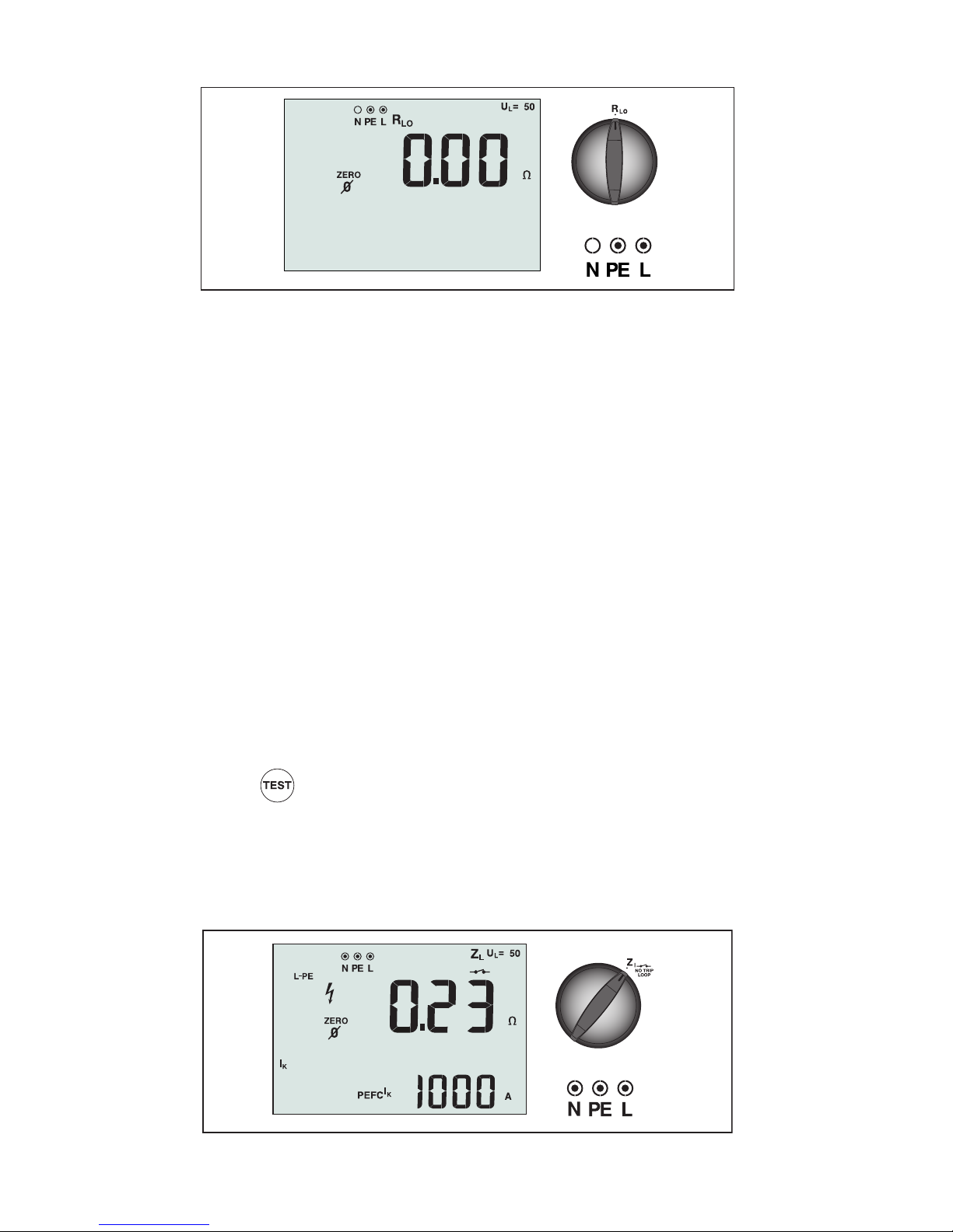
Figure 5. Continuity Zero Display/Switch and Terminal Settings
A continuity test is used to verify the integrity of connections by making a high resolution
resistance measurement. This is especially important for checking Protective Earth
connections.
Note: In countries where electrical circuits are laid out in a ring, it is recommended that you
make an end-to-end check of the ring at the electrical panel.
WWarning
• Measurements should only be performed on de-energized circuits.
• Measurements may be adversely affected by impedances or parallel circuits or transient
currents.
To measure continuity:
1. Turn the rotary switch to the RLO position.
2. Use the L and PE (red and green) terminals for this test.
3. Before making a continuity test, use the Zero adapter to zero the test leads. Press and
hold until the ZERO annunciator appears. The tester measures probe resistance,
stores the reading in memory, and subtracts it from readings. The resistance value is
saved even when power is turned off so you don’t need to repeat the operation every
time you use the instrument.
Note: Be sure the batteries are in good charge condition before you compensate the
test leads.
4. Press and hold
until the reading settles. If the continuity beeper is enabled, the
tester beeps continuously for measured values less than 2 Ω and there is no stable
reading beep for measured values 2 ohms or greater. If a circuit is live, the test is
inhibited and the AC voltage appears in the secondary (lower) display.
Measuring Loop/Line Impedance
Figure 6. Loop/Line Impedance/Switch and Terminal Settings
Page 17
13
Loop Impedance (Line to Protective Earth L-PE)
Loop impedance is source impedance measured between Line (L) and Protective Earth (PE).
You can also ascertain the Prospective Earth Fault Current (PEFC) that is the current that
could potentially flow if the phase conductor is shorted to the protective earth conductor.
The tester calculates the PEFC by dividing the measured mains voltage by the loop
impedance. The loop impedance function applies a test current that flows to earth. If RCDs
are present in the circuit, they may trip. To avoid tripping, always use the Zl No Trip function
on the rotary switch. The no trip test applies a special test that prevents RCDs in the system
from tripping. If you are certain no RCDs are in the circuit, you can use the Zl Hi Current
function for a faster test.
Note: If the L and N terminals are reversed, the tester will auto-swap them internally and
continue testing. If the tester is configured for UK operation, testing will halt. This condition
is indicated by arrows above or below the terminal indicator symbol (
).
To measure loop impedance no trip mode:
WWarning
To prevent tripping RCDs in the circuit:
• Always use the
position for loop measurements.
• Preload conditions can cause the RCD to trip.
• An RCD with a nominal fault current of 10 mA will trip.
Note: To do a Loop impedance test in a circuit with a 10 mA RCD, we recommend a trip time
RCD test. Use a nominal test current of 10 mA and the factor x ½ for this test.
If the fault voltage is below 25 V or 50 V, dependent on the local requirement, the loop is
good. To calculate the loop impedance, divide the fault voltage by 10 mA (Loop impedance
= fault voltage x 100).
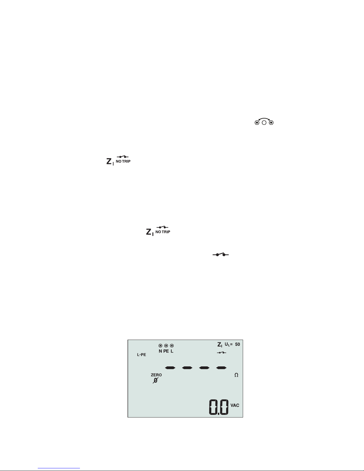
1. Turn the rotary switch to the
position.
2. Connect all three leads to the L, PE, and N (red, green, and blue) terminals of the tester.
3. Press F1 to select L-PE. The display shows the Z
I
and indicator.
4. Before you do a loop impedance test, use the zero adapter to zero the test leads or the
mains cord. Press and hold for more than two seconds until the ZERO annunciator
appears. The tester measures the lead resistance, stores the reading in memory, and
subtracts it from readings. The resistance value is saved even when the power is turned
off so it is unnecessary to repeat the operation each time you use the tester with the
same test leads or mains cord.
Note: Be sure the batteries are in good charge condition before you zero the test leads.
5. Connect all three leads to the L, PE, and N of the system under test or plug the mains
cord into the socket under test.
Figure 7. Display After Zeroing
Page 18
14
6. Press and release
. Wait for the test to complete. The primary (upper) display shows
the loop impedance.
7. To read the Prospective Earth Fault Current, press the key and select lK. The
Prospective Earth Fault Current appears in amps or kilo amps in the secondary (lower)
display.
8. If the mains is too noisy, Err 5 will be displayed. (The measured value accuracy is
degraded by the noise.) Press the down arrow
to display the measured value. Press the
up arrow to return to the Err 5 display.
This test will take several seconds to complete. If the mains is disconnected while the test is
active, the test automatically terminates.
Note: Errors may occur due to preloading the circuit under test.
To measure loop impedance—Hi current trip mode:
If no RCDs are present in the system under test, you can use the high current Line Earth (LPE) loop impedance test.
1. Turn the rotary switch to the
position.
2. Connect all three leads to the L, PE, and N (red, green, and blue) terminals of the tester.
3. Press F1 to select L-PE. The
appears to indicate that hi current trip mode is
selected.
4. Repeat Steps 4 through 8 from the preceding test.
WWarning
The symbol
on the LCD indicates the high current loop mode - any RCDs in the system
will trip - ensure there are no RCDs present.
Earth Resistance Testing by Loop Method
You can also use the tester to measure the earth resistance component of the total loop
resistance. Check your local regulations to determine if this method is acceptable in your
area. You can use three leads or the mains cord to perform this test. Use the connection
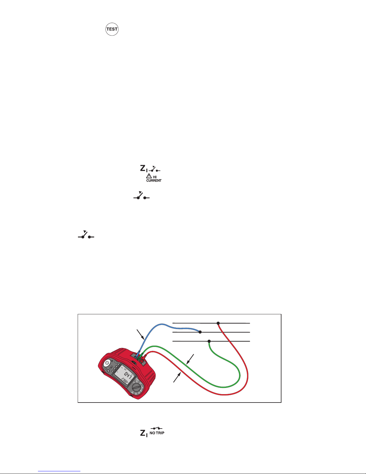
shown in Figure 8 when making a 3-wire connection for earth resistance loop test. Zero the
test leads (see sequence for Loop Impedance measurement).
L
N
PE
PE (Green)
L (Red)
N (Blue)
Figure 8. 3-Wire Connection for Earth Resistance Loop Test
To measure earth resistance using the loop test no trip mode:
1. Turn the rotary switch to the position
Page 19
15
2. Press to select L-PE.
3. Press to select RE (resistance).
4. Press and release . Wait for the test to complete.
• The primary (upper) display shows the loop impedance.
• The secondary (lower) display shows the earth resistance.
Line Impedance
Line impedance is source impedance measured between Line conductors or Line and
Neutral. This function allows the following tests:
• Line to Neutral loop impedance.
• Line to Line impedance in 3-phase systems.
• L-PE loop measurement. This is a way of making a high current, 2-wire loop
measurement. It cannot be used on circuits protected by RCDs because it will cause
them to trip.
• Prospective Short Circuit Current (PSC). PSC is the current that can potentially flow if
the phase conductor is shorted to the neutral conductor or another phase conductor.
The tester calculates the PSC current by dividing the measured mains voltage by the
line impedance.
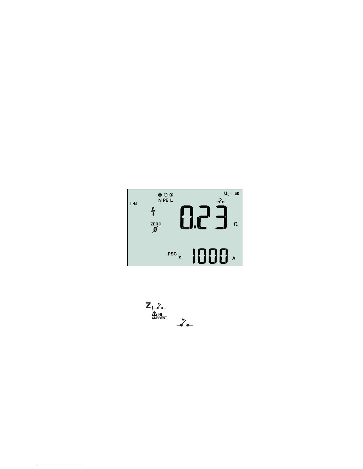
Figure 9. Line Impedance Display
To measure line impedance:
1. Turn the rotary switch to the
position. The LCD indicates that the high current
loop mode is selected by displaying the symbol.
2. Connect the red lead to the L (red) and the blue lead to the N (blue) terminals of the
tester.
3. Press F1 to select L-N.
4. Use the zero adapter to zero the test leads or the mains cord.
5. Press and hold for more than two seconds until the ZERO annunciator appears.
The tester measures the lead resistance, stores the reading in memory, and subtracts it
from readings. The resistance value is saved even when the power is turned off so it is
unnecessary to repeat the operation each time you use the tester with the same test
leads or mains cord.
Note: Be sure the batteries are in good charge condition before you zero the test leads.
Page 20
16
WWarning
At this step, be careful not to select L-PE because a high current loop test will take place.
Any RCDs in the system will trip if you proceed.
Note: Connect the leads in a single-phase test to the system line and neutral. To measure
line-to-line impedance in a 3-phase system, connect the leads to 2 phases.
7. Press and release
. Wait for the test to complete.
• The primary (upper) display shows the line impedance.
• The secondary (lower) display shows the Prospective Short Circuit Current (PSC).
8. If the mains is too noisy, Err 5 will be displayed. (The measured value accuracy is
degraded by the noise). Press the down arrow
to display the measured value. Press the
up arrow to return to the Err 5 display.
Use the connection shown in Figure 10 when measuring in a 3-phase 500 V system.
L1
L2
L3
L (L1/Red)
N (L3/Blue)
Figure 10. Measuring in a 3-Phase System
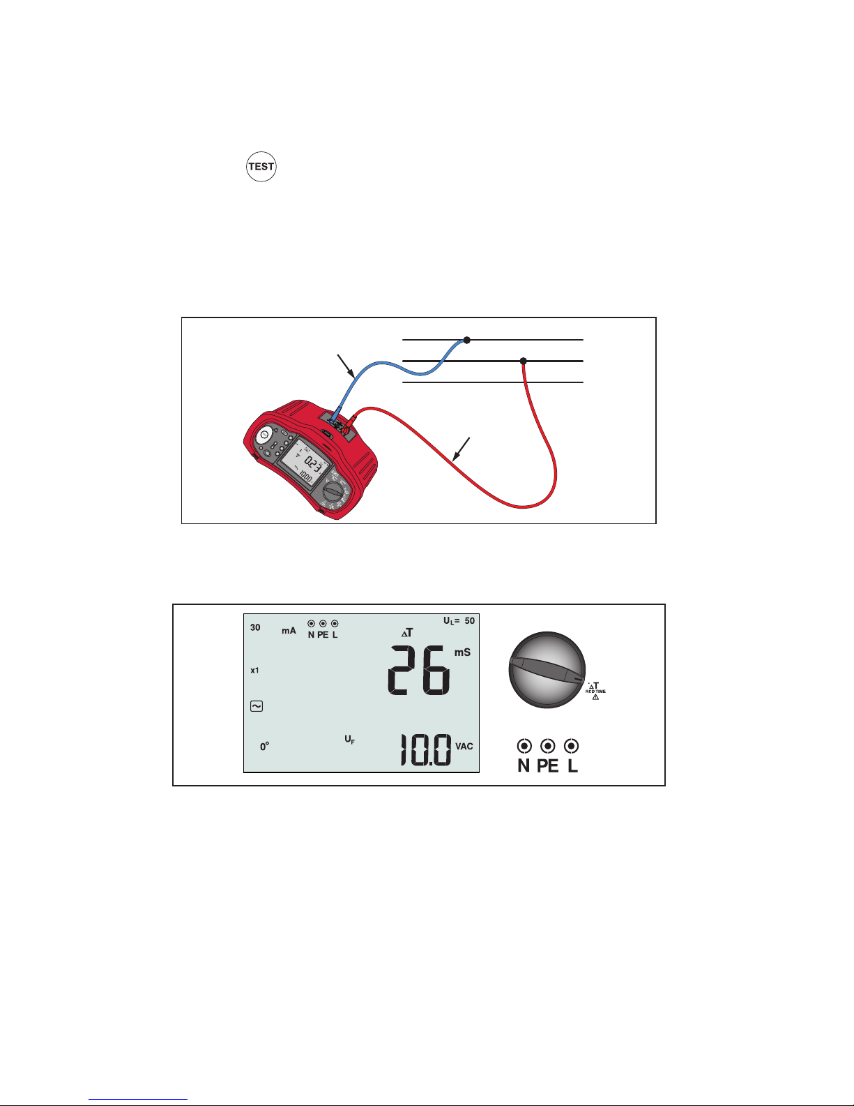
Measuring RCD Tripping Time
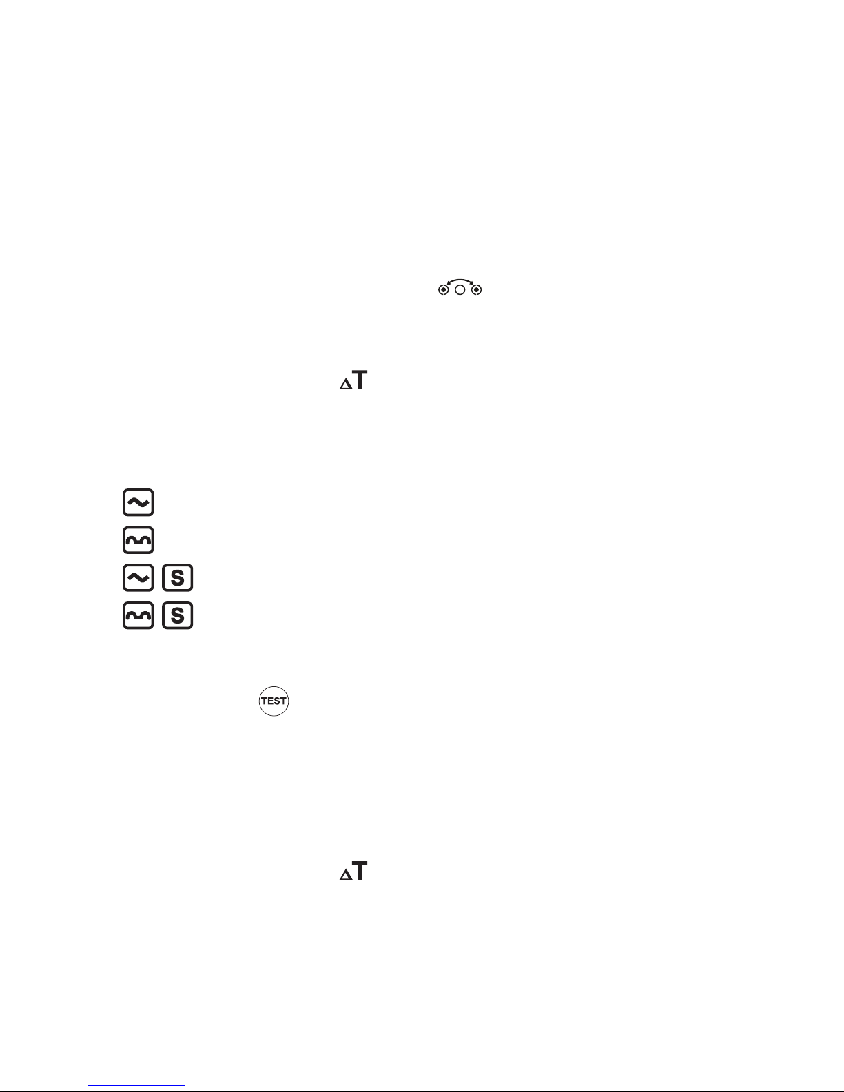
Figure 11. RCD Tripping Time Display/Switch and Terminal Settings
In this test, a calibrated fault current is induced into the circuit, causing the RCD to trip. The
meter measures and displays the time required for the RCD to trip. You can perform this test
with test leads or using the mains cord. The test is performed with a live circuit.
You can also use the tester to perform the RCD tripping time test in Auto mode, which
makes it easier for one person to perform the test. If the RCD has a special nominal current
setting other than the standard options, 10, 30, 100, 300, 500 1000 mA, you can use a
custom setting with the VAR mode.
Note: When measuring trip time for any type of RCD, the tester first does a pretest to
determine if the actual test will cause a fault voltage exceeding the limit (25 or 50 V).
To avoid having an inaccurate trip time for S type (time delay) RCDs, a 30 second delay is
activated between the pretest and the actual test. This RCD type needs a delay because it
contains RC circuits that are required to settle before applying the full test.
Page 21
17
WWarning
• Test the connection between the N-conductor and earth before starting the test. A
voltage between the N-conductor and earth may influence the test.
• Leakage currents in the circuit following the residual current protection device may
influence measurements.
• The displayed fault voltage relates to the rated residual current of the RCD.
• Potential fields of other earthing installations may influence the measurement.
• Equipment (motors, capacitors) connected downstream of the RCD may cause
considerable extension of the tripping time.
Note: If the L and N terminals are reversed, the tester will auto-swap them internally and
continue testing. If the tester is configured for UK operation, testing will halt and you will
need to determine why the L and N are swapped. This condition is indicated by arrows
above or below the terminal indicator symbol (
).
Type A RCDs do not have the 1000 mA option available.
To measure RCD tripping time:
1. Turn the rotary switch to the
position.
2. Press F1 to select the RCD current rating (10, 30, 100, 300, 500, or 1000 mA).
3. Press F2 to select a test current multiplier (x ½, x 1, x 5, or Auto). Normally you will use
x 1 for this test.
4. Press F3 to select the RCD test-current waveform:
– AC current to test type AC (standard AC RCD) and type A (pulse-DC sensitive RCD)
– Half-wave current to test type A (pulse-DC sensitive RCD)
– Delayed response to test S-type AC (time delayed AC RCD)
– Delayed response to S-type A (time delayed pulse-DC sensitive RCD)
5. Press F4 to select the test current phase, 0° or 180°. RCDs should be tested with both
phase settings, as their response time can vary significantly depending on the phase.
6. Press and release
. Wait for the test to complete.
• The primary (upper) display shows the trip time.
• The secondary (lower) display shows the fault voltage (N to PE) related to the rated
residual current.
• If the trip time is according to the appropriate standard of the RCD, the RCD indicator
displays. For more information, see Maximum Trip Time Table on page 31.
To measure RCD tripping time for a custom RCD setting – VAR mode:
1. Turn the rotary switch to the
position.
2. Press to select the VAR current rating. The current custom setting shows on the
primary display. Use the
arrow keys to adjust the value.
3. Press to select a test current multiplier. Normally you will use x 1/2 or x 1 for this test.
4. Repeat steps 4 through 6 listed in the preceding RCD tripping time procedure.
5. To view the nominal setting used for the test, depress the
arrow key.
Note: The maximum setting for type A RCDs is 700 mA.
Page 22
18
To measure RCD tripping time using Auto mode:
1. Plug the tester into the outlet.
2. Turn the rotary switch to the
position.
3. Press F1 to select the RCD current rating (10, 30, or 100 mA).
4. Press F2 to select Auto mode.
5. Press F3 to select the RCD test-current waveform.
6. Press and release
The tester supplies ½x the rated RCD current for 310 or 510 ms (2 seconds in the UK). If
the RCD trips, the test terminates. If the RCD does not trip, the tester reverses phase and
repeats the test. The test terminates if the RCD Trips.
If the RCD does not trip, the tester restores the initial phase setting and supplies 1x
the rated RCD current. The RCD should trip and the test results appear in the primary
display.
7. Reset the RCD.
8. The tester reverses phases and repeats the 1x test. The RCD should trip and the test
results appear in the primary display.
9. Reset the RCD.
10. The tester restores the initial phase setting and supplies 5x the rated RCD current for
up to 50 ms. The RCD should trip and the test results appear in the primary display.
11. Reset the RCD.
12. The tester reverses phase and repeats the 5x test. The RCD should trip and the test
results appear in the primary display.
13. Reset the RCD.
• You can use the
arrow keys to review test results. The first result shown is the
last measurement taken, the 5x current test. Press the down arrow key to move
backward to the first test at ½x the rated current.
Measuring RCD Tripping Current
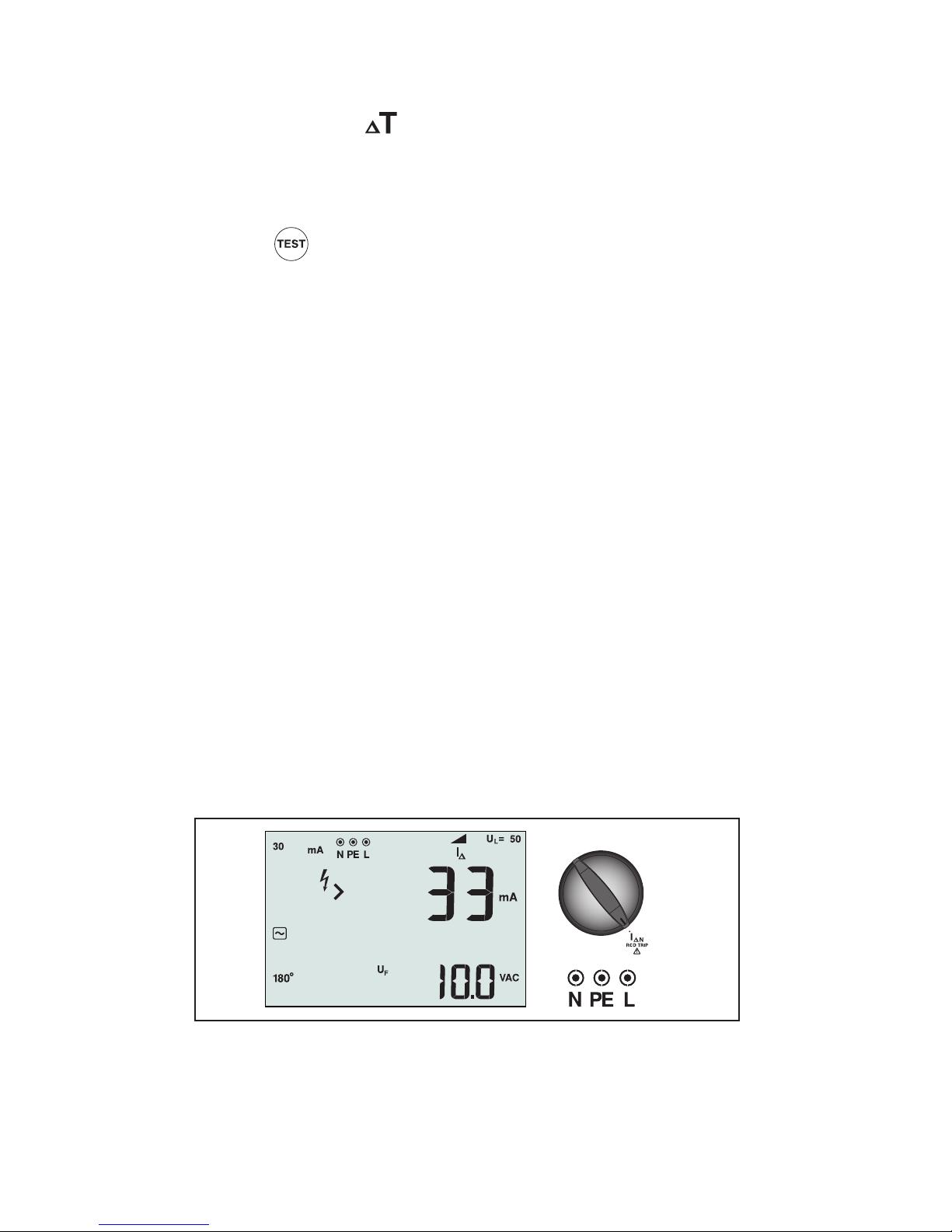
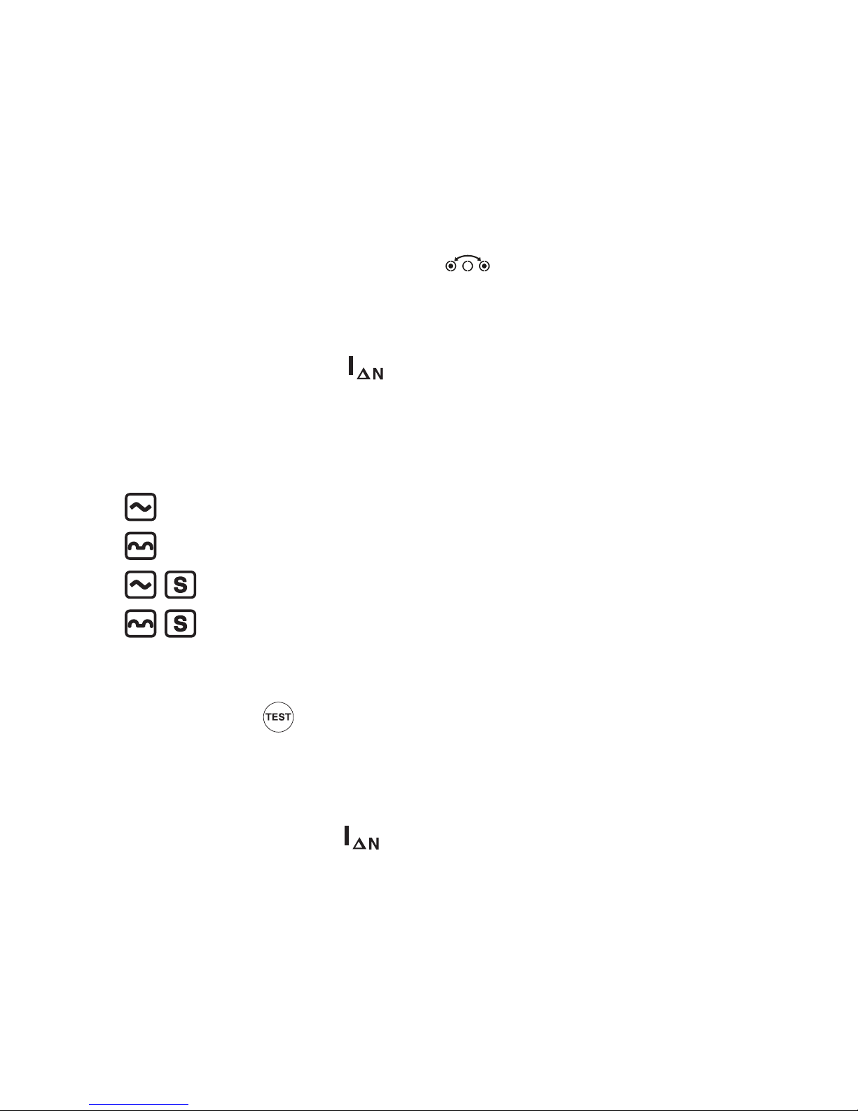
Figure 12. RCD Tripping Current/Switch and Terminal Settings
This test measures the RCD tripping current by applying a test current and then gradually
increasing the current until the RCD trips. You can use the test leads or mains cord for this
test. A 3-wire connection is required.
Page 23
19
WWarning
• Test the connection between the N-conductor and earth before starting the test. A
voltage between the N-conductor and earth may influence the test.
• Leakage currents in the circuit following the residual current protection device may
influence measurements.
• The displayed fault voltage relates to the rated residual current of the RCD.
• Potential fields of other earthing installations may influence the measurement.
Note: If the L and N terminals are reversed, the tester will auto-swap them internally and
continue testing. If the tester is configured for UK operation, testing will halt and you will
need to determine why the L and N are swapped. This condition is indicated by arrows
above or below the terminal indicator symbol (
).
Type A RCDs do not have the 1000 mA option available.
To measure RCD tripping current:
1. Turn the rotary switch to the
position.
2. Press F1 to select the RCD current rating (10, 30, 100, 300, or 500 mA). If the RCD has a
special nominal current setting other than the standard options, 10, 30, 100, 300, 500
1000 mA, you can use a custom setting with the VAR mode.
3. Press F2 to select the RCD test-current waveform:
– AC current to test type AC (standard AC RCD) and type A (pulse-DC sensitive RCD)
– Half-wave current to test type A (pulse-DC sensitive RCD)
– Delayed response to test S-type AC (time delayed AC RCD)
– Delayed response to S-type A (time delayed pulse-DC sensitive RCD)
4. Press F4 to select the test current phase, 0° or 180°. RCDs should be tested with both
phase settings, as their response time can vary significantly depending on the phase.
5. Press and release
. Wait for the test to complete.
• The primary (upper) display shows the RCD trip current.
• If the trip current is according to the appropriate standard of the RCD, the RCD
indicator displays. For more information, see Maximum Trip Time Table on page 31.
To measure RCD tripping current for a custom RCD setting - VAR mode:
1. Turn the rotary switch to the
position.
2. Press to select the VAR current rating. The current custom setting shows on the
primary display. Use the
arrow keys to adjust the value.
3. Repeat steps 3 through 5 listed in the preceding RCD tripping current procedure.
4. To view the nominal test setting, depress the
arrow key.
Note: The maximum setting for RCDs is 700 mA.
Page 24
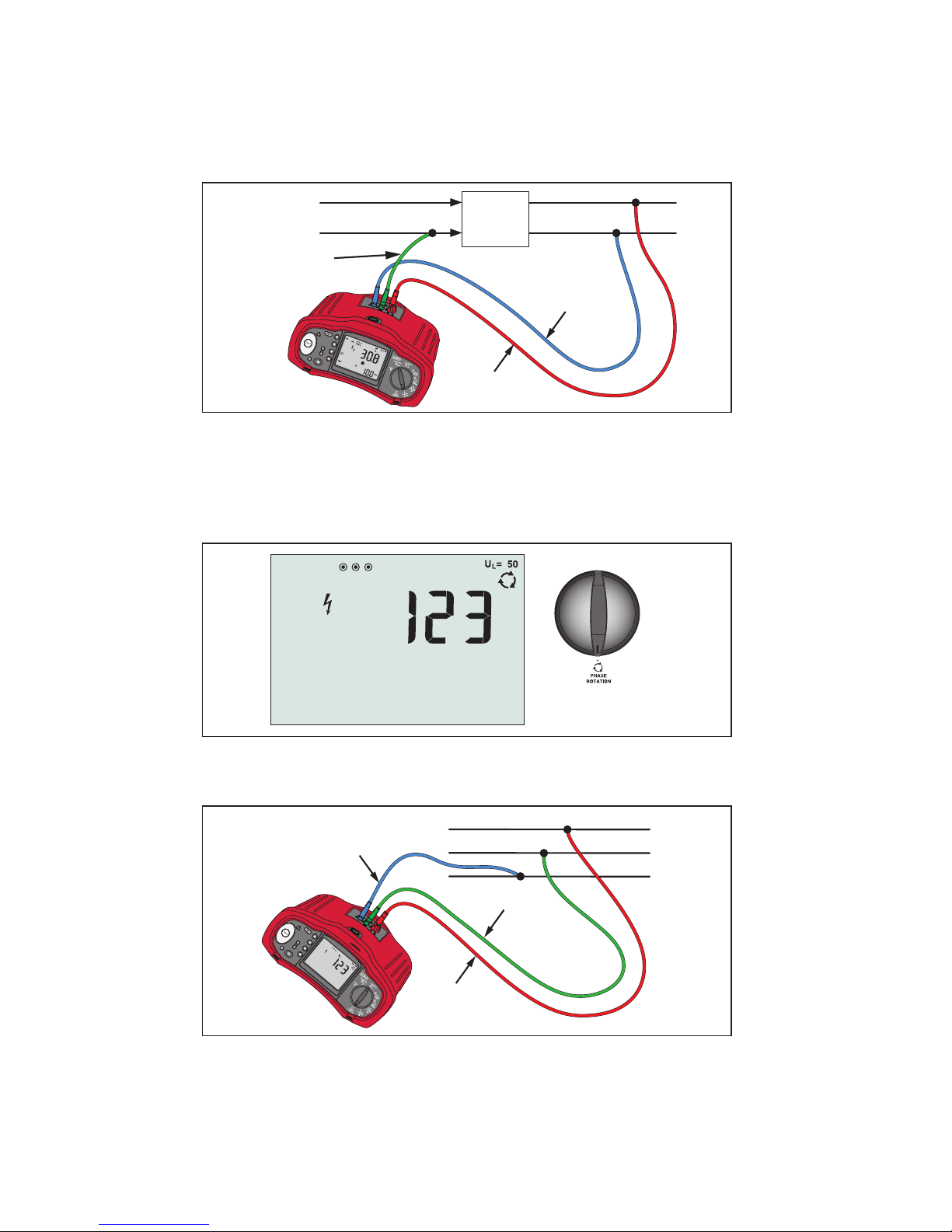
20
RCD testing in IT systems
RCD testing at locations with IT systems requires a special test procedure because the
Protective Earth connection is grounded locally and is not tied directly to the power system.
The test is conducted at the electrical panel using probes. Use the connection shown in
Figure 13 when performing RCD testing on IT electrical systems.
RCD
Mains Supply
PE (L2/Green)
L (L1/Red)
N (L3/Blue)
Figure 13. Connection for RCD Testing on IT Electrical Systems
The test current flows through the upper side of the RCD, into the L terminal, and returns
though the PE terminal.
Testing Phase Sequence
Figure 14. Phase Sequence Display/Switch and Terminal Settings
Use the connection shown in Figure 15 for a phase sequence test connection.
L1
L2
L3
PE (L2/Green)
L (L1/Red)
N (L3/Blue)
Figure 15. Phase Sequence Test Connection
Page 25

21
To perform a phase sequence test:
1. Turn the rotary switch to the
position.
2. The primary (upper) display shows:
• 123 for correct phase sequence.
• 321 for reversed phase sequence.
• Dashes (---) instead of numbers if insufficient voltage is sensed.
MAINTAINING THE TESTER
Cleaning
Periodically wipe the case with a damp cloth and mild detergent. Do not use abrasives or
solvents.
Dirt or moisture in the terminals can affect readings.
To clean the terminals:
1. Turn the meter off and remove all test leads.
2. Shake out any dirt that may be in the terminals.
3. Soak a new swab with alcohol. Work the swab around each terminal.
Testing and Replacing the Batteries
Battery voltage is continuously monitored by the tester. If the voltage falls below 6.0 V
(1.0 V/cell), the low battery icon M appears on the display, indicating that there is minimal
battery life left. The low battery icon continues to appear on the display until you replace
the batteries.
WWarning
To avoid false readings, which could lead to possible electric shock or personal injury,
replace the batteries as soon as the battery icon ( M ) appears.
Be sure that the battery polarity is correct. A reversed battery can cause leakage.
Replace the batteries with six AA batteries. Alkaline batteries are supplied with the tester
but you can also use 1.2 V NiCd or NiMH batteries. You can also check the battery charge so
that you can replace them before they discharge.
WWarning
To avoid electrical shock or personal injury, remove the test leads and any input signals
before replacing the battery. To prevent damage or injury, install ONLY specified
replacement fuses with the amperage, voltage, and speed ratings shown in the General
Specifications section of this manual.
To test the batteries:
1. Turn the rotary switch to the V position.
2. Press F3 > 2 seconds to initiate the battery test. The Voltage function display clears and
is replaced by the measured battery voltage in the secondary display for 2 seconds, the
Voltage function display then returns.
Page 26
22
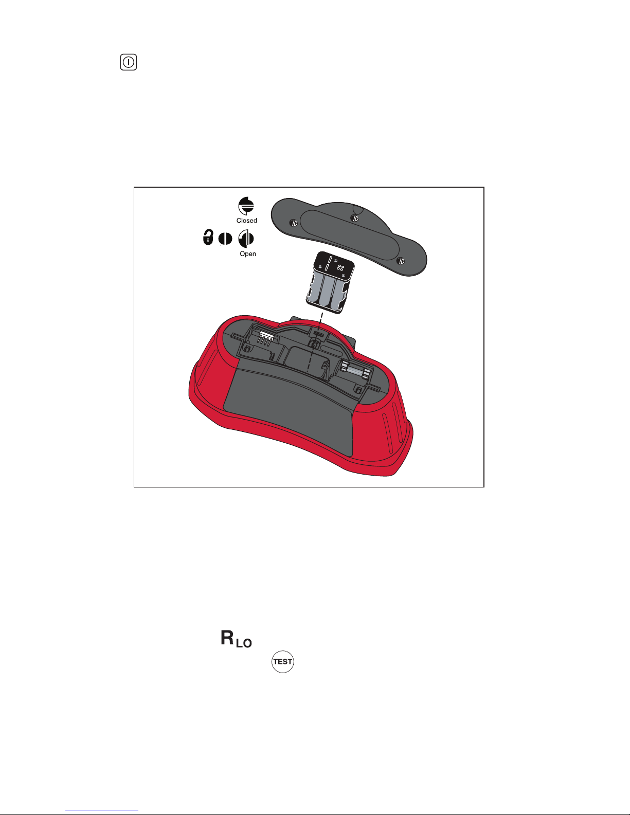
To replace the batteries (refer to Figure 16):
1. Press
to turn the tester off.
2. Remove the test leads from the terminals.
3. Remove the battery door by using a standard-blade screwdriver to turn the battery door
screws (3) one-quarter turn counterclockwise.
4. Press the release latch and slide the battery holder out of the tester.
5. Replace the batteries and the battery door.
6. Secure the door by turning the screws one-quarter turn clockwise.
Figure 16. Replacing the Batteries
Testing the Fuse
A fuse test is performed each time you turn on the tester. If leads are plugged into the L and
PE terminals, the fuse test is skipped. If a blown fuse is detected, testing is disabled, FUSE
appears on the primary display, and the tester issues a warning beep.
You can also perform a manual check of the fuse.
To manually check the fuse:
1. Turn the rotary switch to
switch setting.
2. Short the leads and press and hold
3. If the fuse is bad, FUSE or Err1 will appear on the display to indicate the tester is
damaged and needs repair. Contact Beha-Amprobe Service for repair (see Contacting
Beha-Amprobe).
Page 27
23
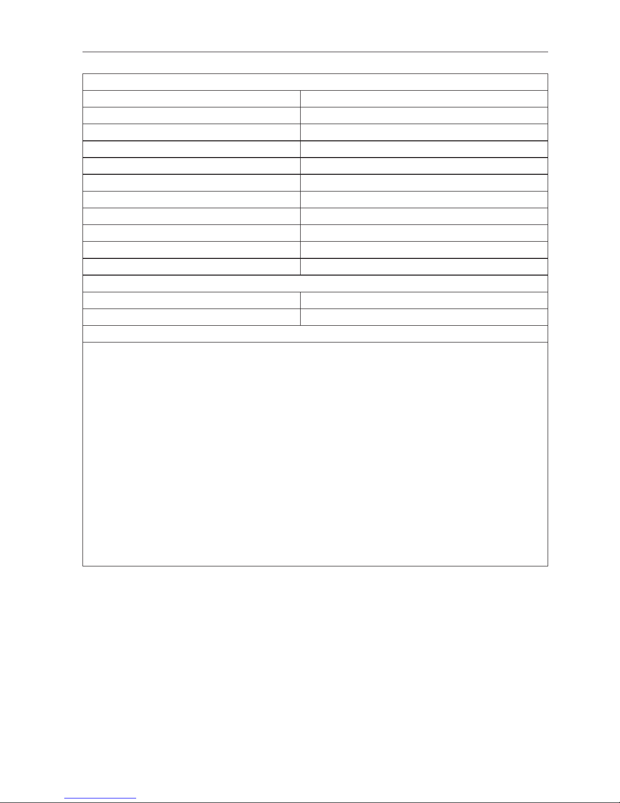
DETAILED SPECIFICATIONS
Features
Measurement Function
Voltage & Frequency √
Wiring polarity checker √
Insulation Resistance √
Loop & Line Resistance √
Prospective Short-Circuit current (PSC/I
K
) √
RCD switching time √
RCD tripping level √ ramp test
RCD variable current √
Automatic RCD test sequence √
Test pulse current sensitive RCDs (Type A) √
Phase Sequence Indicator √
Other Features
Self-test √
Illuminated Display √
Included Accessories
• Test lead set
• ProInstall-TL-UK (LC38 AMP-MFT, mains test cord)
• Alligator clips
• Test probe
• ProInstall-TL-KIT (Remote test probe and probe tips)
• ProInstall-CC (Soft case with carrying strap)
• TL-75 ( Fused test probe, red/blue/green with lantern spring, cap and tip cover)
• Zero-Adapter
• Statement of calibration
• Batteries
• Quick reference guide
• Carry strap for neck/waist
• CD-ROM (User manual)
Page 28
24
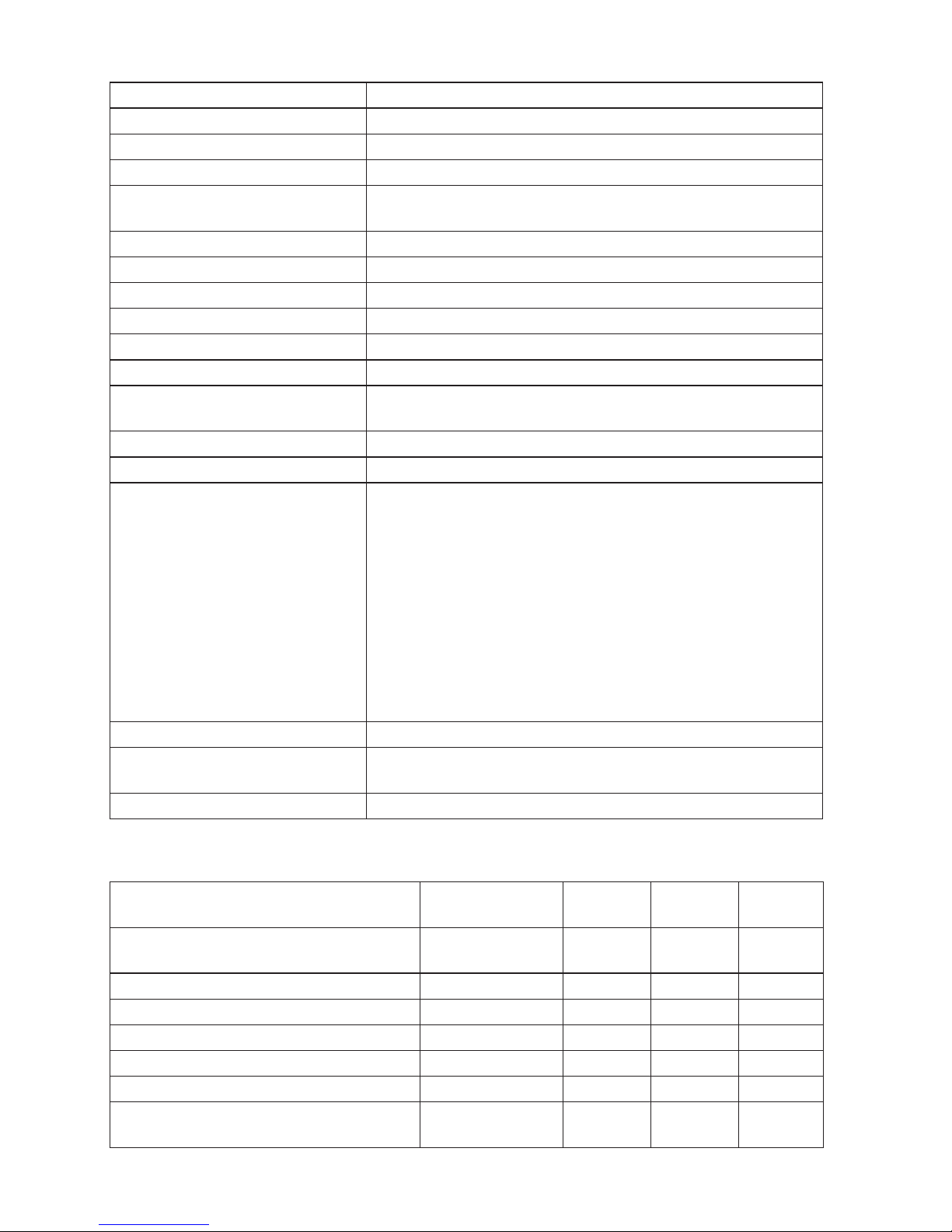
General Specifications
Specification Characteristic
Size 10 cm (L) x 25 cm (W) x 12.5 cm (H)
Weight (with batteries) 1.3 kg
Battery size, quantity Type AA, 6 ea.
Battery type Alkaline supplied.
Usable with 1.2 V NiCd or NiMH batteries (not supplied)
Battery life (typical) 200 hours idling
Fuse T3.15 A, 500 V, 1.5 kA 6.3 x 32 mm (PN 2030852)
Operating Temperature -10 °C to 40 °C
Storage Temperature -10 °C to 60 °C indefinitely (to -40 °C for 100 hrs)
Relative Humidity 80 % 10 to 35 °C; 70 % 35 to 40 °C
Operating Altitude 0 to 2000 meters
Shock, Vibration Vibration to Class 3 per MIL-PRF-28800F
1 meter drop test, six sides, oak floor
Sealing IP 40
EMC Complies with EN61326-1
Safety Complies with EN61010-1
Overvoltage Category: 500 V/CAT III, 300 V/CAT IV
Measurement Category III is for measurements
performed in the building installation. Examples are
distribution panels, circuit breakers, wiring and cabling.
Category IV equipment is designed to protect against
transients from the primary supply level, such as an
electrical meter or an overhead or underground utility
service.
Performance EN61557-1, EN61557-2, EN61557-3,
EN61557-4, EN61557-6, EN61557-7. EN61557-10.
Pollution Degree 2
Maximum voltage between
any terminal and earth ground
500 V
Surge Protection 6 kV peak per EN 61010-1
Category Ratings and Usage
Part/Accessory Printed
CAT Rating
CAT II
250 V
CAT III
500 V
CAT IV
300 V
Electrical Installation Tester CAT III 500 V
CAT IV 300 V
√
√
√
√
√
√
ProInstall-TL-UK, British Mains Cord CAT II 250 V √
ProInstall-TL-Kit Remote Test Probe (red) CAT III 1000 V √ √ √
Test Lead (red/green/blue) CAT III 1000 V √ √ √
Test Probe (red/green/blue) CAT III 1000 V √ √ √
Alligator Clip (red/green/blue) CAT III 1000 V √ √ √
TL-75 Fused Test Probes:
(red/green/blue)
CAT III 1000 V
CAT IV 600 V
√
√
√
√
√
√
Page 29
25
ELECTRICAL MEASUREMENT SPECIFICATIONS
The accuracy specification is defined as ±(% reading +digit counts) at 23 °C ±5 °C,
≤80 % RH. Between -10 °C and 18 °C and between 28 °C and 40 °C, accuracy specifications
may degrade by 0,1 x (accuracy specification) per °C. The following tables can be used for
the determination of maximum or minimum display values considering maximum instrument
operating uncertainty per EN61557-1, 5.2.4.
Insulation Resistance (R
ISO
)
250 V 500 V 1000 V
Limit Value
Maximum
Display Value
Limit Value
Maximum
Display Value
Limit Value
Maximum
Display Value
1 1.3 1 1.3 1 1.3
2 2.4 2 2.4 2 2.4
3 3.5 3 3.5 3 3.5
4 4.6 4 4.6 4 4.6
5 5.7 5 5.7 5 5.7
6 6.8 6 6.8 6 6.8
7 7.9 7 7.9 7 7.9
8 9.0 8 9.0 8 9.0
9 10.1 9 10.1 9 10.1
10 11.2 10 11.2 10 11.2
20 22.2 20 22.2 20 22.2
30 33.2 30 33.2 30 33.2
40 44.2 40 44.2 40 44.2
50 55.2 50 55.2 50 55.2
60 66.2 60 66.2 60 66.2
70 77.2 70 77.2 70 77.2
80 88.2 80 88.2 80 88.2
90 99.2 90 99.2 90 99.2
100 110.2 100 110.2 100 110.2
200 220.2 200 220.2 200 220.2
300 347 300 345
400 462 400 460
500 577 500 575
600 690
700 805
800 920
900 1035
1000 1150
Page 30
26
Continuity (RLO)
Limit Value Maximum Display
Value
Limit Value Maximum Display
Value
0.2 0.16 3 2.68
0.3 0.25 4 3.58
0.4 0.34 5 4.48
0.5 0.43 6 5.38
0.6 0.52 7 6.28
0.7 0.61 8 7.18
0.8 0.7 9 8.08
0.9 0.79 10 8.98
1 0.88 20 17.98
2 1.78 30 26.8
Loop Tests (ZI)
Loop Z
I
Hi Current
Loop Z
I
No Trip
Loop Z
I
Loop R
E
Limit
Value
Maximum
Display
Value
Limit
Value
Maximum
Display
Value
Limit
Value
Maximum
Display
Value
Limit
Value
Maximum
Display
Value
0.20 0.14 - - 3 2.53 3 2.72
0.30 0.23 - - 4 3.38 4 3.62
0.40 0.32 0.40 0.28 5 4.23 5 4.52
0.50 0.41 0.50 0.37 6 5.08 6 5.42
0.60 0.50 0.60 0.45 7 5.93 7 6.32
0.70 0.59 0.70 0.54 8 6.78 8 7.22
0.80 0.68 0.80 0.62 9 7.63 9 8.12
0.90 0.77 0.90 0.71 10 8.48 10 9.02
1.00 0.86 1.00 0.79 20 16.98 20 18.02
1.10 0.95 1.10 0.88 30 25.3 30 27.2
1.20 1.04 1.20 0.96 40 33.8 40 36.2
1.30 1.13 1.30 1.05 50 42.3 50 45.2
1.40 1.22 1.40 1.13 60 50.8 60 54.2
1.50 1.31 1.50 1.22 70 59.3 70 63.2
1.60 1.40 1.60 1.30 80 67.8 80 72.2
1.70 1.49 1.70 1.39 90 76.3 90 81.2
1.80 1.58 1.80 1.47 100 84.8 100 90.2
1.90 1.67 1.90 1.56 200 169.8 200 180.2
2.00 1.76 2.00 1.64 300 253 300 272
- - - - 400 338 400 362
- - - - 500 423 500 452
- - - - 600 508 600 542
Page 31
27
Loop Tests (ZI) (cont.)
- - - - 700 593 700 632
- - - - 800 678 800 722
- - - - 900 763 900 812
- - - - 1000 848 1000 902
RCD/FI Tests (ΔT, IΔN)
RCD/FI Time RCD/FI Current
Limit Value Maximum Display Value Limit Value Maximum Display Value
20 18.1 0.5 0.43
30 27.1 0.6 0.52
40 36.1 0.7 0.61
50 45.1 0.8 0.7
60 54.1 0.9 0.79
70 63.1 1 0.88
80 72.1 2 1.78
90 81.1 3 2.68
100 90.1 4 3.58
200 180.1 5 4.48
300 271 6 5.38
400 361 7 6.28
500 451 8 7.18
600 541 9 8.08
700 631 10 8.98
800 721 20 17.98
900 811 30 26.8
1000 901 40 35.8
2000 1801 50 44.8
60 53.8
70 62.8
80 71.8
90 80.8
100 89.8
200 179.8
300 268
400 358
500 448
Page 32
28
AC Voltage Measurement (V)
Range Resolution Accuracy
50 Hz – 60 Hz
Input Impedance Overload
Protection
500 V 0.1 V 0.8 % + 3 digits 3.3 MΩ 660 V rms
Continuity Testing (RLO)
Range
(Autoranging)
Resolution Open Circuit Voltage Accuracy
20 Ω 0.01 Ω >4 V ±(1.5 % + 3 digits)
200 Ω 0.1 Ω >4 V ±(1.5 % + 3 digits)
2000 Ω 1 Ω >4 V ±(1.5 % + 3 digits)
Note: The number of possible continuity tests with a fresh set of batteries is 3000.
Range R
LO
Test Current
7.5 Ω 210 mA
35 Ω 100 mA
240 Ω 20 mA
2000 Ω 2 mA
Test Probe Zeroing
Press the
to zero the test.
Can subtract up to 3 Ω of lead resistance.
Error message for >3 Ω.
Live Circuit Detection Inhibits test if terminal voltage >10 V ac detected prior to
initiation of test.
Insulation Resistance Measurement (R
ISO
)
Test Voltages 250-500-1000 V
Accuracy of Test Voltage
(at rated test current)
+10 %, -0 %
Test
Voltage
Insulation
Resistance Range
Resolution Test Current Accuracy
250 V 10 kΩ to 20 MΩ 0.01 MΩ 1 mA @ 250 kΩ ±(1.5 % + 3 digits)
20 MΩ to 200 MΩ 0.1 MΩ ±(1.5 % + 3 digits)
500 V 10 kΩ to 20 MΩ 0.01 MΩ 1 mA @ 500 kΩ ±(1.5 % + 3 digits)
20 MΩ to 200 MΩ 0.1 MΩ ±(1.5 % + 3 digits)
200 MΩ to 500 MΩ 1 MΩ ±10 %
1000 V 100 kΩ to 200 MΩ 0.1 MΩ 1 mA @ 1 MΩ ±(1.5 % + 3 digits)
200 MΩ to 1000 MΩ 1 MΩ ±10 %
Note: The number of possible insulation tests with a fresh set of batteries is 2000.
Page 33
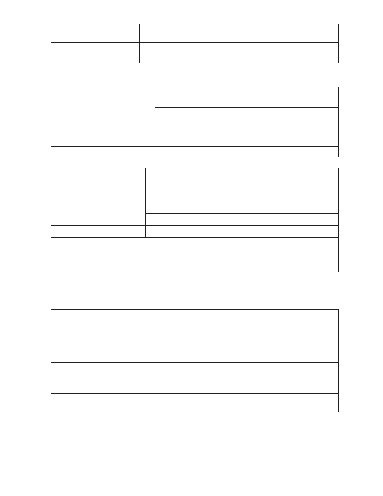
29
Auto Discharge Discharge time constant <0.5 second for C = 1 μF
or less.
Live Circuit Detection Inhibits test if terminal voltage >30 V prior to initiation of test.
Maximum Capacitive Load Operable with up the 5 μF load.
No Trip and Hi Current Modes RCD/FI
Mains Input Voltage Range 100 - 500 V ac (50/60 Hz)
Input Connection
(soft key selection)
Loop Impedance: phase to earth
Line impedance: phase to neutral
Limit on Consecutive Tests Automatic shutdown when internal components are too
hot. There is also a thermal shutdown for RCD tests.
Maximum Test Current @ 400 V 20 A sinusoidal for 10 ms
Maximum Test Current @ 230 V 12 A sinusoidal for 10 ms
Range Resolution Accuracy
[1]
20 Ω 0.01 Ω No Trip mode: ±(3 % + 6 digits)
Hi Current mode: ±(2 % + 4 digits)
200 Ω 0.1 Ω No Trip mode: ±(3 %)
Hi Current mode: ±(2 %)
2000 Ω 1 Ω ±6 %
[2]
Note:
[1] Valid for resistance of neutral circuit <20 Ω and up to a system phase angle of 30 °. Test
leads must be zeroed before testing.
[2] Valid for mains voltage >200 V.
Prospective Short Circuit Current Test (PSC/IK)
Prospective Earth Fault Current (PEFC)
Computation Prospective Earth Fault Current (PSC/IK) or Prospective Short
Circuit Current (PSC/IK) determined by dividing measured
mains voltage by measured loop (L-PE) resistance or line (L-N)
resistance, respectively.
Range 0 to 10 kA or 0 to 50 kA
(See Power-On Options earlier in this manual)
Resolution and Units Resolution Units
I
K
<1000 A 1 A
I
K
>1000 A 0.1 kA
Accuracy Determined by accuracy of loop resistance and mains
voltage measurements.
Page 34
30
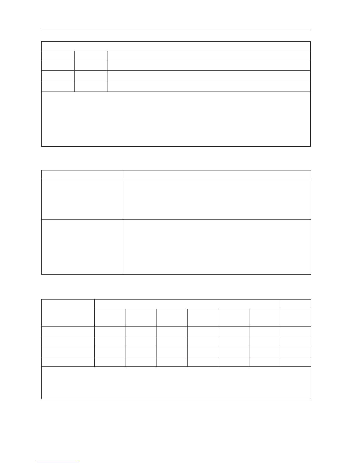
RCD TESTING
RCD Types Tested
RCD Type
[5]
AC
[1]
G
[2]
√
AC S
[3]
√
A
[4]
G √
A S √
Note:
[1] AC – Responds to ac
[2] G – General, no delay
[3] S – Time delay
[4] A – Responds to pulsed signal
[5] RCD test inhibited for V >265 ac
RCD tests permitted only if the selected current, multiplied by earthing resistance, is <50V.
Test Signals
RCD Type Test Signal Description
AC
(sinusoidal)
The waveform is a sinewave starting at zero crossing, polarity
determined by phase selection (0 ° phase starts with low to
high zero crossing, 180 ° phase starts with high to low zero
crossing). The magnitude of the test current is I
P
n x Multiplier
for all tests.
A
(half wave)
The waveform is a half wave rectified sinewave starting at
zero, polarity determined by phase selection (0 ° phase starts
with low to high zero crossing, 180 ° phase starts with high
to low zero crossing). The magnitude of the test current is
2.0 x I
P
n (rms) x Multiplier for all tests for IPn = 0.01A. The
magnitude of the test current is 1.4 x IPn (rms) x Multiplier for
all tests for all other IPn ratings.
RCD Types Tested (PT)
Test Function
RCD Current Selection
10 mA 30 mA 100 mA 300 mA 500 mA 1000
mA
[1]
var
[2]
X ½, 1 √ √ √ √ √ √ √
X 5 √ √ √
Ramp √ √ √ √ √ √ √
Auto √ √ √
Note:
Mains voltage 100 V – 265 V ac, 50/60 Hz
[1] Type AC RCDs only.
[2] Type A RCDs are limited to 700 mA, not available for Type B RCDs.
Page 35
31
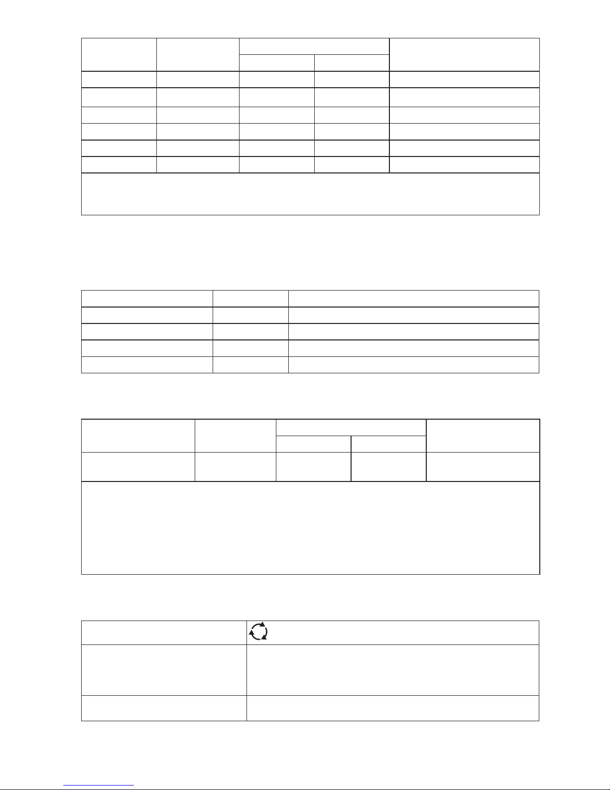
Current
Multiplier
*RCD Type
Measurement Range
Trip Time Accuracy
Europe UK
X ½ G 310 ms 2000 ms ± (1% Reading + 1ms)
X ½ S 510 ms 2000 ms ± (1% Reading + 1ms)
X 1 G 310 ms 310 ms ± (1% Reading + 1ms)
X 1 S 510 ms 510 ms ± (1% Reading + 1ms)
X 5 G 50 ms 50 ms ± (1% Reading + 1ms)
X 5 S 160 ms 160 ms ± (1% Reading + 1ms)
Note:
*G – General, no delay
*S – Time delay
Maximum Trip Time
The RCD √ symbol switches on when testing the RCD trip time if the trip time meets the
following conditions:
RCD I
P
N
Trip Time Limits
AC G, A X 1 Less than 300 ms
AC G-S, A-S X 1 Between 130 ms and 500 ms
AC G, A X 5 Less than 40 ms
AC G-S, A-S X 5 Between 50 ms and 150 ms
RCD/FI-Tripping Current Measurement/Ramp Test ( I
P
N
)
Current Range Step Size
Measurement Range
Measurement
Accuracy
Type G Type S
30 % to 110 % of
RCD rated current
[1]
10 % of I
PN
300 ms/step 500 ms/step ±5 %
Notes
[1] 30 % to 150 % for Type A I
PN
>10 mA
30 % to 210 % for Type A IPN = 10 mA
Specified trip current ranges (EN 61008-1):
50 % to 100 % for Type AC
35 % to 140 % for Type A (>10 mA)
35 % to 200 % for Type A (≤10 mA)
Phase Sequence Indication
Icon
icon Phase Sequence indicator is active.
Display of Phase Sequence Displays “1-2-3” in digital display field for correct
sequence. Displays “3-2-1” for incorrect phase. Dashes in
place of a number indicate a valid determination could
not be made.
Mains Input Voltage Range
(phase-to-phase)
100 to 500 V
Page 36
32
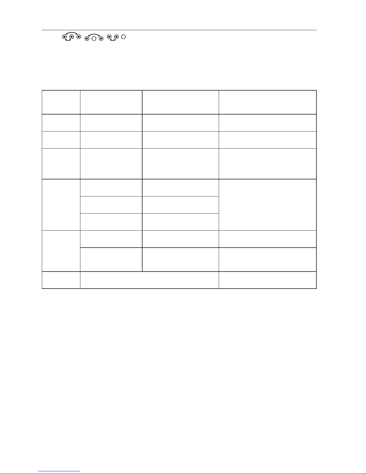
MAINS WIRING TEST
Icons ( , , ) indicate if L-PE or L-N terminals are reversed. Instrument
operation is inhibited and an error code is generated if the input voltage is not between 100 V
and 500 V. The UK Loop and RCD tests are inhibited if the L-PE or the L-N terminals are reversed.
OPERATING RANGES AND UNCERTAINTIES PER EN 61557
Function
Display
Range
EN 61557
Measurement Range
Operating Error
Nominal Values
V
EN 61557-1
0.0 V ac – 500 V ac
50 V ac – 500 V ac
±(2% + 2 dgt)
U
N
= 230/400 V ac
f = 50/60 Hz
R
LO
EN 61557-4
0.00 Ω - 2000 Ω
0.2 Ω - 2000 Ω
± ( 10% + 2 dgt )
4,0 VDC < U
Q
< 24 VDC
R
LO
≤ 2.00 Ω IN ≥ 200 mA
R
ISO
EN 61557-2
0.00 MΩ - 1000 MΩ
1 MΩ - 200 MΩ
± ( 10% + 2 dgt )
200 MΩ - 1000 MΩ
± ( 15% + 2 dgt )
U
N
= 250 / 500 / 1000 V dc
I
N
= 1,0 mA
Z
I
EN 61557-3
Z
I
(NO TRIP)
0.00 Ω - 2000 Ω
0.4 Ω - 2000 Ω
± ( 15% + 6 dgt )
U
N
= 230 / 400 Vac
f = 50 / 60 Hz
I
K
= 0 A - 10.0 kA
Z
I
(HI CURRENT)
0.00 Ω - 2000 Ω
0.2 Ω - 200 Ω
± ( 10% + 4 dgt )
RE
0.0 Ω - 2000 Ω
10 Ω - 1000 Ω
±(10 % + 2 dgt)
∆T, I
∆N
EN 61557-6
∆T
0.0 ms - 2000 ms
25 ms - 2000 ms
± ( 10% + 1 dgt )
∆T@ 10 / 30 / 100 / 300 /
500 / 1000 / VAR mA
I
∆N
3 mA - 550 mA
(VAR 3 mA – 700
mA)
3 mA - 550 mA
± ( 10% + 1 dgt )
I
∆N
= 10 / 30 / 100 / 300 / 500 /
VAR mA
Phase
EN 61557-7
1 : 2 : 3
Page 37
33
Operating Uncertainties per EN 61557
The Operating Uncertainty shows the maximum possible uncertainty when all influence
factors E1-E10 are counted.
Volts
R
LO
EN 61557-4
R
ISO
EN 61557-2
Z
I
EN 61557-3∆TEN 61557-6
I
∆N
EN 61557-6
Intrinsic
Uncertainty A
0.80 % 1.50 % 10.00 % 6.00 % 1.00 % 5.00 %
Influence
Quantity
Volts
R
LO
EN 61557-4
R
ISO
EN 61557-2
Z
I
EN 61557-3∆TEN 61557-6
I
∆N
EN 61557-6
E1 - Position 0.00 % 0.00 % 0.00 % 0.00 % 0.00 % 0.00 %
E2 - Supply
Voltage
0.50 % 3.00 % 3.00 % 3.00 % 3.00 % 2.75 %
E3 Temperature
0.50 % 3.00 % 3.00 % 3.00 % 3.00 % 2.75 %
E4 - Series
Interferences
Voltage
- - - - - -
E5 - Resistance
of the probes
and auxiliary
earth electrodes
- - - - - -
E6.2 - System
phase angle
- - - 1.00 % - -
E7 - System
frequency
- - - 2.50 % - -
E8 - System
voltage
- - - 2.50 % 2.50 % 2.50 %
E9 - Harmonics - - - 2.00 % - -
E10 - D.C.
Quantity
- - - 2.50 % - -
Page 38

Please
Recycle
Beha-Amprobe
®
In den Engematten 14
79286 Glottertal, Germany
Phone: +49 (0) 7684 8009 - 0
beha-amprobe.de
Beha-Amprobe
®
UK
52 Hurricane Way
Norwich, Norfolk
NR6 6JB United Kingdom
Phone: +44 (0) 1603 25 6662
beha-amprobe.com
Beha-Amprobe
®
Science Park Eindhoven 5110
5692 EC Son
The Netherlands
Phone: +31 (0) 40 267 51 00
beha-amprobe.com
Visit beha-amprobe.com for
• Catalog
• Application notes
• Product specifications
• User manuals
 Loading...