


IR608A
Infrared Thermometer
User Manual
• Mode d’emploi
• Bedienungshandbuch
• Manual de uso
• Manuale d’Uso
• Anvandärhanbok

IR608A
Infrared Thermometer
User Manual
! Mode d’emploi
! Bedienungshandbuch
! Manual de uso
! Manuale d’Uso
! Anvandärhanbok
PN 2461571
March 2007
© 2007 Amprobe Test Tools.
All rights reserved. Printed in China
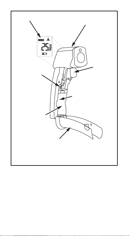
• Display
• Anzeige
• Affichage
• Pantalla
• Display
• ˚C/˚F Switch
• ˚C/˚F-Schalter
• Commutateur ˚C/˚F
• Interruptor de ˚C/˚F
• Chave ˚C/˚F
• Serial Number Label
• Battery Compartment
• Batteriefach
• Boîtier piles
• Compartimento de las pilas
• Compartimento de bateria
• Battery Cover
• Batterieabdeckung
• Couvercle du boîtier pile
• Tapa de las pilas
• Tampa da bateria
• Laser
• Laser
• Laser
• Láser
• Laser
• Trigger
• Messtaste
• Gâchette
• Gatillo
• Gatilho

IR608A
Infrared Thermometer
User Manual
! Mode d’emploi
! Bedienungshandbuch
! Manual de uso
! Manuale d’Uso
! Anvandärhanbok
English

Limited Warranty and Limitation of Liability
Your Amprobe product will be free from defects in material and
workmanship for 1 year from the date of purchase. This warranty
does not cover fuses, disposable batteries or damage from
accident, neglect, misuse, alteration, contamination, or abnormal
conditions of operation or handling. Resellers are not authorized
to extend any other warranty on Amprobe’s behalf. To obtain
service during the warranty period, return the product with proof
of purchase to an authorized Amprobe Test Tools Service Center
or to an Amprobe dealer or distributor. See Repair Section for
details. THIS WARRANTY IS YOUR ONLY REMEDY. ALL OTHER
WARRANTIES - WHETHER EXPRESS, IMPLIED OR STAUTORY INCLUDING IMPLIED WARRANTIES OF FITNESS FOR A
PARTICULAR PURPOSE OR MERCHANTABILITY, ARE HEREBY
DISCLAIMED. MANUFACTURER SHALL NOT BE LIABLE FOR
ANY SPECIAL, INDIRECT, INCIDENTAL OR CONSEQUENTIAL
DAMAGES OR LOSSES, ARISING FROM ANY CAUSE OR
THEORY. Since some states or countries do not allow the
exclusion or limitation of an implied warranty or of incidental or
consequential damages, this limitation of liability may not apply
to you.
Contents
Symbols...............................................................................1
Introduction.........................................................................2
Specifications ......................................................................2
How it Works.......................................................................3
How to Operate the Unit ......................................................3
C/F and Battery..............................................................3
Operating the Unit .........................................................3
Display...........................................................................3
How to Accurately Measure Temperature............................3
Locating a Hot Spot.......................................................3
Field of View..................................................................4
Distance and Spot Size..................................................4
Reminders.....................................................................4
Emissivity ............................................................................4
Maintenance ........................................................................4
Troubleshooting ..................................................................5
CE Certification ....................................................................5
Repair ..................................................................................5
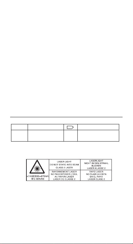
Symbols
!" Refer to the manual
Complies with EU
#"
directives
Do not point laser directly at eye or indirectly off
reflective surfaces.
BT
"
! Warning
" Battery
1

All models should be protected from the
following,
! EMF (electro-magnetic fields) from arc
welders, induction heaters
! Static electricity
! Thermal shock (caused by large or abrupt
ambient temperature changes—allow 30
minutes for unit to stabilize before use)
! Do not leave the unit on or near objects of
high temperature
Cautions
••••••
Introduction
We are confident you will find many uses for your handheld
noncontact thermometer. Compact, rugged, and easy to use—
just aim, pull the trigger, and read current surface temperatures
in less than a second. You can safely measure surface
temperatures of hot, hazardous, or hard-to-reach objects without
contact.
Specifications
Note
Specifications subject to change without notice.
Temperature range.............. -18 to 400 °C (0 to 750 °F)
Temperature display.................. °C or 0.5 °F
Accuracy (assumes ambient operating temperature of 23 °C [73
°F]) For targets at:
-1 to 400 °C (30 to 750 °F) ....... ±2% of reading or ± 2 °C (± 3.5
-18 to -1 °C (0 to 30 °F): ........... ±3 °C (±5 °F) at 23 °C (73 °F)
Repeatability..................... ± 2 % of reading, or ± 2 °C
Response time ................... 500 mSec, 95% response
Spectral response...................... 7–18 µm
Emissivity......................... pre-set 0.95
°F), whichever is greater
±2 ºC (±3.5 ºF)
(±3 °F)
2

Ambient operating range.......... 0 to 50 °C (32 to 120 °F)
Relative humidity................ 10–95 % RH noncondensing, @
Storage temperature ............ - 20° to 65°C (-4° to 150°F)
Weight / Dimensions............ 227 g (0.5 lb); 152 x 101 x 38
Power.............................. 9V Alkaline or NiCd battery
Typical Battery life (Alkaline) ..... 12 hrs
Distance to Spot Size................. 8:1
up to 30°C (86°F)
without battery
mm (6 x 4 x 1.5 in)
How it Works
Infrared thermometers measure the surface temperature of an
object. The unit’s optics sense emitted (E), reflected (R), and
transmitted (T) energy, which is collected and focused onto a
detector. The unit’s electronics translate the information into a
temperature reading which is displayed on the unit.
How to Operate the Unit
C/F and Battery
Pull open the unit’s handle using the finger indents near the
trigger to access the C/F switch or to insert/remove the battery.
To toggle between °C and °F, push the switch (A). Insert the 9v
battery positive side first into the battery compartment.
The battery door is detachable.
NOTE
Operating the Unit
To measure a temperature, point unit at object and pull the
trigger. Be sure to consider distance-to-spot size ratio and field
of view. If the unit is equipped with a laser, use the laser only for
aiming. See How to Accurately Measure Temperatures.
Display
The backlit LCD displays the current temperature in Celsius or
Fahrenheit. The unit will hold the reading for 7 seconds after
trigger is released; the word HOLD appears. The presence of the
battery icon indicates a low battery (B).
How to Accurately Measure Temperature
Locating a Hot Spot
To find a hot spot aim the thermometer outside the area of
interest, then scan across with an up and down motion until you
locate the hot spot.
3

Field of View
Make sure that the target is larger than the unit’s spot size. The
smaller the target, the closer you should be to it. When accuracy
is critical, make sure the target is at least twice as large as the
spot size.
Distance and Spot Size
As the distance (D) from the object increases, the spot size (S) of
the area measured by the unit becomes larger.
Reminders
Not recommended for use in measuring shiny or polished metal
surfaces (stainless steel, aluminum, etc.). See Emissivity.
The unit cannot measure through transparent surfaces such as
glass. It will measure the surface temperature of the glass
instead.
Steam, dust, smoke, etc., can prevent accurate measurement by
obstructing the unit’s optics.
Emissivity
Most organic materials and painted or oxidized surfaces have an
emissivity of 0.95 (pre-set in the unit). Inaccurate readings will
result from measuring shiny or polished metal surfaces. To
compensate, cover the surface to be measured with masking
tape or flat black paint. Allow time for the tape to reach the same
temperature as the the material underneath it. Measure the
temperature of the tape or painted surface.
Maintenance
Lens Cleaning: Blow off loose particles using clean compressed
air. Gently brush remaining debris away with a camel's hair
brush. Carefully wipe the surface with a moist cotton swab. The
swab may be moistened with water.
DO NOT use solvents to clean the plastic lens.
Case Cleaning: Use soap and water on a damp sponge or soft
cloth.
DO NOT submerge the unit in water.
Note
Note
4

Troubleshooting
Code Problem Action
---(on display)
Battery icon
appears
Blank display
Laser doesn’t work
Target temperature
is over or under
range
Possible low
battery
Possible dead
battery
Low or dead
battery
Select target
within
specifications
Check and/or
replace battery
Check and/or
replace battery
Replace battery
CE Certification
This instrument conforms to the following
#
EN 61326-1 Electromagnetic Emissions and Susceptibility
EN 61010-1 General Safety
EN 60825-1 Laser Safety
Between approximately 250Mhz and 800 Mhz at 3V/m, the
instrument may not meet its stated accuracy.
Repair
All test tools returned for warranty or non-warranty repair or for
calibration should be accompanied by the following: your name,
company’s name, address, telephone number, and proof of
purchase. Additionally, please include a brief description of the
problem or the service requested and include the test leads with
the meter. Non-warranty repair or replacement charges should
be remitted in the form of a check, a money order, credit card
with expiration date, or a purchase order made payable to
Amprobe® Test Tools.
In-Warranty Repairs and Replacement – All Countries
Please read the warranty statement and check your battery
before requesting repair. During the warranty period any
defective test tool can be returned to your Amprobe® Test Tools
distributor for an exchange for the same or like product. Please
check the “Where to Buy” section on www.amprobe.com for a
list of distributors near you. Additionally, in the United States and
Canada In-Warranty repair and replacement units can also be
sent to a Amprobe® Test Tools Service Center.
standards
5

Non-Warranty Repairs and Replacement – US and Canada
Non-warranty repairs in the United States and Canada should be
sent to a Amprobe® Test Tools Service Center. Call Amprobe®
Test Tools or inquire at your point of purchase for current repair
and replacement rates.
In USA In Canada
Amprobe Test Tools Amprobe Test Tools
Everett, WA 98203 Mississauga, ON L4Z 1X9
Tel: 877-AMPROBE (267-7623) Tel: 905-890-7600
Non-Warranty Repairs and Replacement – Europe
European non-warranty units can be replaced by your
Amprobe® Test Tools distributor for a nominal charge. Please
check the “Where to Buy” section on www.amprobe.com for a
list of distributors near you.
European Correspondence Address*
Amprobe® Test Tools Europe
P.O. Box 1186
5602 BD Eindhoven
The Netherlands
*(Correspondence only – no repair or replacement available from
this address. European customers please contact your
distributor.)
6

s
IR608A
Infrared Thermometer
User Manual
! Mode d’emploi
! Bedienungshandbuch
! Manual de uso
! Manuale d’Uso
! Anvandärhanbok
Français
Françai

Limites de garantie et de responsabilité
Amprobe garantit l’absence de vices de matériaux et de
fabrication de ce produit dans des conditions normales
d’utilisation et d’entretien pendant une période d’un an prenant
effet à la date d’achat. Cette garantie ne s’applique pas aux
fusibles, aux piles jetables ni à tout produit mal utilisé, modifié,
contaminé, négligé ou endommagé par accident ou soumis à des
conditions anormales d’utilisation et de manipulation. Les
distributeurs agréés par Amprobe ne sont pas autorisés à
appliquer une garantie plus étendue au nom de Amprobe. Pour
bénéficier de la garantie, renvoyez le produit accompagné d’un
justificatif d’achat auprès d’un centre de services agréé par
Amprobe Test ou du distributeur ou du revendeur Amprobe. Voir
la section Réparation ci-dessus pour tous les détails. LA
PRESENTE GARANTIE EST LE SEUL ET EXCLUSIF RECOURS
TOUTES AUTRES GARANTIES, EXPLICITES, IMPLICITES OU
STATUTAIRES, NOTAMMENT LE CAS ECHEANT LES
GARANTIES DE QUALITE MARCHANDE OU D’ADAPTATION A
UN OBJECTIF PARTICULIER SONT EXCLUES PAR LES
PRESENTES. LE FABRICANT NE SERA EN AUCUN CAS TENU
RESPONSABLE DE DOMMAGES PARTICULIERS, INDIRECTS,
ACCIDENTELS OU CONSECUTIFS, NI D’AUCUNS DEGATS OU
PERTES DE DONNEES, SUR UNE BASE CONTRACTUELLE,
EXTRA-CONTRACTUELLE OU AUTRE. Etant donné que certains
pays ou états n’admettent pas les limitations d’une condition de
garantie implicite, ou l’exclusion ou la limitation de dégâts
accidentels ou consécutifs, les limitations et les exclusions de
cette garantie ne s’appliquent pas obligatoirement à chaque
acheteur.
Contents
Symboles.............................................................................1
Introduction.........................................................................2
Caractéristiques techniques.................................................2
Principe de fonctionnement.................................................3
Principe de fonctionnement.................................................3
°C/°F et pile ...................................................................3
Utilisation du thermomètre............................................3
Affichage .......................................................................3
Comment mesurer précisément la température ..................4
Détermination d’un point chaud ....................................4
Champ de visée .............................................................4
Distance et taille du spot mesuré ..................................4
Rappels................................................................................4
Emissivité ............................................................................4
Entretien ..............................................................................4
Dépannage...........................................................................5
Homologation CE.................................................................5
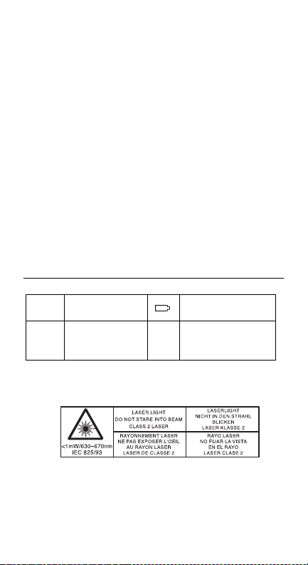
Symboles
!"
Se reporter au
mode d’emploi
BT
" Pile
Conforme aux
#"
directives de
l’UE
Ne pointez pas le rayon laser directement dans les yeux
ou indirectement sur des surfaces réfléchissantes.
"
! Avertissement
Tous les modèles doivent être protégés contre:
Précautions
1
••••••

! les champs électromagnétiques des postes de
soudure, les appareils de chauffage par
induction
l’électricité statique
!
les chocs thermiques (causés par d’importants
!
ou de brusques changements de température laissez le thermomètre se stabiliser pendant
30 minutes avant de l’utiliser)
Ne laissez pas le thermomètre sur ou à
!
proximité d’objets à température élevée.
Introduction
Nous sommes certains que vous trouverez plusieurs utilisations
pour le thermomètre portable sans contact. Compact, robuste et
facile à utiliser – il suffit de viser et d’appuyer sur la gâchette
pour lire la température courante de surface en moins d’une
seconde. Vous pouvez ainsi mesurer sans contact et en toute
sécurité les températures de surface d’objets dangereux ou
difficiles d’accès.
Caractéristiques techniques
Les spécifications sont susceptibles d'être
modifiées sans préavis.
Gamme de températures ............ de -18 à 400 °C (0 à 750 °F)
Affichage des températures..............°C ou 0,5 °F
Précision (en supposant une température ambiante de
fonctionnement de 23 °C [73 °F])
Pour les cibles à :
-1 à 400 °C (30 à 750 °F) : ..............± 2 % de la lecture ou ± 2 °C
-18 à -1 °C (0 à 30 °F):.....................± 3 °C (± 5 °F) à 23 °C (73
Fidélité des mesures.......................± 2 % de lecture ou ± 2 °C
Temps de réponse ...........................500 mS, réponse à 95 %
Réponse spectrale ............................7 à 18 µm
Remarque
(± 3,5 °F) selon le plus
élevé des deux
°F) ± 2 °C (± 3,5 °F)
(± 3 °F)]
••••••
2

Emissivité ........................................prédéfinie à 0,95
Gamme de fonctionnement ambiant.de 0 à 50 °C (32 à 120 °F)
Humidité relative.............................10 à 95 % HR sans
Température de stockage................-20 à 65 °C (-4 à 150 °F)
Poids/Dimensions............................227 g (0,5 lb); 152 x 101 x
Alimentation ....................................Pile alcaline 9V ou batterie
Durée de vie (pile alcaline)................12 h
Rapport de distance à taille de point.8:1
Principe de fonctionnement
Les thermomètres à infrarouge mesurent la temperature de
surface d’un objet. L’optique de l’instrument capte l’énergie
émise, réfléchie et transmise; celle-ci est recueillie, puis dirigée
sur un détecteur. L’électronique du thermomètre traduit cette
information et affiche la température. Le rayon laser (des
thermomètres qui en sont équipés) sert uniquement à viser
l’objet.
condensation, jusqu’à 30
°C (86 °F)
sans batterie
38 mm (6 x 4 x 1,5
pouces)
NiCd
Principe de fonctionnement
°C/°F et pile
Pour passer des degrés Celsius aux degrés Fahrenheit, ouvrez le
couvercle du boîtier à piles et appuyez sur le bouton (A) pour
sélectionner C ou F. Lorsque cela s’avère nécessaire, remplacez
la pile 9 V comme indiqué sur le schéma.
Utilisation du thermomètre
Pour mesurer une température, pointez l’instrument sur un objet
et appuyez sur la gâchette. Veillez à tenir compte du champ de
visée et du rapport distancedimension du spot. Si le
thermomètre est équipé d’un laser, n’utilisez ce dernier que pour
pointer sur l’objet. Voir « Mesure de la température avec
précision ».
Affichage
L’écran à cristaux liquides, rétro-éclairé, affiche la température
courante en degrés Celsius ou Fahrenheit. La température restera
affichée pendant 7 secondes après avoir relâché le bouton et que
le mot HOLD (maintenir) apparaît. Lorsque l’icône de la pile
apparaît, cela indique un faible niveau de charge de la pile (B).
3

Comment mesurer précisément la température
Détermination d’un point chaud
Pour trouver un point chaud, pointez le thermometer hors de la
zone d’intérêt, puis balayez d’un movement de haut en bas
jusqu’à localisation du point chaud.
Champ de visée
Assurez-vous que la cible est plus grande que le spot mesuré par
le thermomètre. Plus la cible est petite, plus vous devrez vous en
rapprocher. Lorsqu’il est essentiel d’obtenir des mesures
précises, veillez à ce que la cible soit au moins deux fois plus
grande que le spot mesuré.
Distance et taille du spot mesuré
La taille du spot mesuré (S) s’accroît avec la distance (D)
séparant le thermomètre de la cible.
Rappels
Il est déconseillé d’utiliser ce thermomètre pour mesurer la
température de surfaces métalliques, brillantes ou polies (acier
inoxydable, aluminium, etc.). Voir Emissivité.
Le thermomètre ne peut pas mesurer la temperature à travers
des surfaces transparentes comme le verre, car il mesure en fait
la température de surface du verre.
La précision des résultats peut être faussée par la présence de
vapeur, de poussière, de fumée... etc.
Emissivité
La plupart des matières organiques, ainsi que les surfaces
peintes ou oxydées ont une émissivité de 0,95 (préréglée dans le
thermomètre). Des résultats inexacts peuvent s’afficher en
mesurant la température de surfaces métalliques brillantes ou
polies. Pour corriger cela, couvrez la surface à mesurer à l’aide
de ruban adhesive (résistant à la température mesurée) ou d’une
peinture noire mate. Laissez le ruban adhésif atteindre la même
température que le matériau recouvert. Mesurez la temperature
de la surface recouverte.
Entretien
Nettoyage de l’optique : ôtez les particules libres en soufflant de
l’air comprimé propre. Eliminez les débris restants en brossant
délicatement à l’aide d’une brosse en poils de chameau. Essuyez
avec précaution la surface à l’aide d’un coton-tige humide (que
vous pouvez humidifier avec de l’eau).
N’utilisez PAS de solvant pour nettoyer l’optique en
plastique.
Nettoyage du boîtier : utilisez une éponge humide ou un linge
doux imbibés d’eau savonneuse.
REMARQUE
4

REMARQUE
N’immergez PAS le thermomètre dans l’eau.
Dépannage
Code Problème Action
– – – (sur
l’affichage)
L’icône de la pile
Pas d’affichage Pile déchargée Remplacez la pile
Le laser ne
fonctionne pas
Homologation CE
# Cet instrument est conforme aux normes suivantes:
EN 61326-1 Electromagnetic Emissions and Susceptibility
EN 61010-1 General Safety
EN 60825-1 Laser Safety
Entre 250 MHz et 800 MHz environ à 3V/m cet appareil peut ne
pas avoir la précision indiquée.
Réparation
Tous les appareils qui sont envoyés pour réparation ou calibrage
dans le cadre de la garantie ou en dehors de la garantie doivent
être accompagnés de ce qui suit : Nom du client, nom de la
firme, adresse, numéro de téléphone et preuve d'achat. Prière de
joindre en outre à l'appareil de mesure une brève description du
problème ou de la maintenance désirée ainsi que les lignes de
mesure. Les frais pour les réparations en dehors de la garantie
ou pour le remplacement d'instruments doivent être payés par
chèque, virement bancaire, carte de crédit (numéro de carte de
crédit avec date d'expiration) ou une commande doit être
formulée au bénéfice de Amprobe Test Tools.
Température cible
hors limites
Pile faiblement
chargée
Pile faiblement
chargée ou
déchargée
Sélectionnez une
cible conforme aux
spécifications
Vérifier et/ou
changer la pile
Remplacez la pile
5

Réparations ou remplacement sous garantie – tous les pays.
Veuillez lire la déclaration de garantie subséquente et contrôler la
pile avant de demander des réparations. Pendant la période de
garantie, tous les appareils défectueux peuvent être renvoyés à
un distributeur Amprobe Test Tools pour remplacement par un
appareil identique ou un produit similaire. Un répertoire des
distributeurs agréés se trouve dans la section « Where to Buy »
(points de vente) sur le site web www.amprobe.com. De plus,
aux USA et au Canada, les appareils peuvent être envoyés à un
centre de service après-vente Amprobe Test Tools (adresse voir
plus loin) pour réparation ou remplacement.
Réparations ou remplacement en dehors de la garantie - USA
et Canada
Pour les réparations en dehors de la garantie aux Etats-Unis et
au Canada, les appareils sont envoyés à un centre de service
après-vente Amprobe Test Tools. Vous pouvez obtenir des
renseignements sur les prix de réparation et de remplacement
actuellement en vigueur auprès de Amprobe Test Tools ou du
point de vente.
Aux USA : Au Canada :
Amprobe Test Tools Amprobe Test Tools
Everett, WA 98203 Mississauga, ON L4Z 1X9
Tél. : 877-AMPROBE (267-7623) Tél. : 905-890-7600
Réparations ou remplacement en dehors de la garantie Europe
Les appareils hors garantie peuvent être remplacés contre
paiement par le distributeur Amprobe Test Tools compétent. Un
répertoire des distributeurs agréés se trouve dans la section «
Where to Buy » (points de vente) sur le site web
www.amprobe.com.
6

IR608A
Infrared Thermometer
User Manual
! Mode d’emploi
! Bedienungshandbuch
! Manual de uso
! Manuale d’Uso
! Anvandärhanbok
Deutsch

Beschränkte Gewährleistung und
Haftungsbeschränkung
Es wird gewährleistet, dass dieses Amprobe-Produkt für die
Dauer von einem Jahr ab dem Kaufdatum frei von Material- und
Fertigungsdefekten ist. Diese Gewährleistung erstreckt sich nicht
auf Sicherungen, Einwegbatterien oder Schäden durch Unfälle,
Nachlässigkeit, Missbrauch, Änderungen oder abnormale
Betriebsbedingungen bzw. unsachgemäße Handhabung. Die
Verkaufsstellen sind nicht dazu berechtigt, diese Gewährleistung
im Namen von Amprobe zu erweitern. Um während der
Gewährleistungsperiode Serviceleistungen zu beanspruchen, das
Produkt mit Kaufnachweis an ein autorisiertes Amprobe Test
Tools Service-Center oder an einen Amprobe-Fachhändler/Distributor einsenden. Einzelheiten siehe Abschnitt „Reparatur“
oben. DIESE GEWÄHRLEISTUNG STELLT DEN EINZIGEN UND
ALLEINIGEN RECHTSANSPRUCH AUF SCHADENERSATZ DAR.
ALLE ANDEREN GEWÄHRLEISTUNGEN - VERTRAGLICH
GEREGELTE ODER GESETZLICHE VORGESCHRIEBENE EINSCHLIESSLICH DER GESETZLICHEN GEWÄHRLEISTUNG
DER MARKTFÄHIGKEIT UND DER EIGNUNG FÜR EINEN
BESTIMMTEN ZWECK, WERDEN ABGELEHNT DER
HERSTELLER ÜBERNIMMT KEINE HAFTUNG FÜR SPEZIELLE,
INDIREKTE, NEBEN- ODER FOLGESCHÄDEN ODER VERLUSTE,
DIE AUF BELIEBIGER URSACHE ODER RECHTSTHEORIE
BERUHEN. Weil einige Staaten oder Länder den Ausschluss oder
die Einschränkung einer implizierten Gewährleistung sowie von
Begleit- oder Folgeschäden nicht zulassen, ist diese
Gewährleistungsbeschränkung möglicherweise für Sie nicht
gültig.
Contents
Symbole...............................................................................1
Einführung...........................................................................2
Technische Daten ................................................................2
Funktionsweise....................................................................3
Bedienung des Gerätes........................................................3
°C/°F und Batterie..........................................................3
Bedienung des Gerätes..................................................3
Anzeige..........................................................................3
So können Sie präzise die Temperatur messen...................4
Finden einer Temperaturabweichung.............................4
Sichtfeld ........................................................................4
Entfernung und Messfleckgröße....................................4
Hinweise..............................................................................4
Emissionsgrad.....................................................................4
Wartung...............................................................................4
Fehlersuche und -behebung ................................................5
CE=Zertifizierung .................................................................5
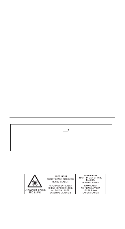
Symbole
!"
Im Handbuch
nachlesen.
BT
" Batterie
Übereinstimmu
#"
ng mit EURichtlinien
Richten Sie den Laser nicht direkt oder indirekt über
reflektierende Oberflächen auf die Augen.
"
! Warnung
1

Alle Modelle müssen vor folgenden Zuständen
geschützt werden:
! EMF (elektromagnetische Felder) von
! statischer Elektrizität
! Thermischer Schock (verursacht durch
Vorsichtsmaßnahmen
Elektroschweißgeräten,
Induktionsheizgeräten
große oderplötzliche
Temperaturänderungen – Gerät
vorGebrauch 30 Minuten lang stabilisieren
lassen)
Einführung
Wir sind überzeugt, dass Sie für Ihr handgehaltenes
berührungsloses Thermometer zahlreiche Anwendungen finden
werden. Kompakt, robust und einfach zu bedienen – einfach auf
das Ziel richten, den Knopf drücken, und in weniger als einer
Sekunde können Sie die momentane Oberflächentemperatur
ablesen. So lassen sich die Oberflächentemperaturen von heißen,
gefährlichen oder schwer erreichbaren Objekten gefahrlos und
ohne Berührung bestimmen.
Technische Daten
Technische Daten können ohne Vorankündigung geändert
werden.
Temperaturbereich.........................-18 bis 400 °C (0 bis 750 °F)
Temperaturanzeige ...........................°C oder 0,5 °F
Genauigkeit (angenommene Umgebungs-betriebstemperatur
23°C [73 °F]) Für Ziele mit:
-1 bis 400 °C (30 bis 750 °F)...........± 2 % der Anzeige oder ±
-18 bis -1 °C (0 bis 30 °F): .............± 3 °C (± 5 °F) bei 23 °C (73
Wiederholbarkeit ± 2 % der Anzeige oder ± 2
Ansprechzeit ...................................500 ms, 95 % Reaktion
Spektralreaktion...............................7–18 µm
Hinweis:
2 °C (± 3,5 °F), je nachdem
was höher ist
°F) ± 2 °C (± 3,5 °F)
°C (± 3 °F)
••••••
2

Emissivität .......................................0,95 voreingestellt
Umgebungsbetriebstemperatur ......0 bis 50 °C (32 bis 120 °F)
Relative Luftfeuchtigkeit .................10–95 % RL nicht
Lagerungstemperatur......................-20 bis 65 °C (-4 bis 150 °F)
Gewicht/Abmessungen....................227 g (0,5 lb); 152 x 101 x
Stromversorgung .............................9V Alkali- oder NiCd-Batterie
Typische Batterielebensdauer (Akali)12 h
Verhältnis Abstand zu Punktgröße....8:1
Funktionsweise
Infrarot-Thermometer messen die Oberflächentemperatur eines
Objekts (target). Die Optik des Gerätes erfasst die emittierte (E),
reflektierte (R) und durchgelassene (T) Wärmestrahlung, die
gebündelt und auf einen Detektor fokussiert wird. Die
Geräteelektronik wandelt diese Information in einen
Temperaturwert um, der auf dem Display angezeigt wird. Bei
Geräten mit einem Laser wird der Laser lediglich zum Zielen
verwendet.
kondensierend, bis zu 30 °C
(86 °F)
ohne Batterie
38 mm (6 x 4 x 1,5 Zoll)
Bedienung des Gerätes
°C/°F und Batterie
Um zwischen Celsius und Fahrenheit umzuschalten, müssen Sie
das Batteriefach öffnen und durch Drücken des Schalters (A) C
oder F wählen. Die 9-Volt-Batterie wird wie in der Abbildung
dargestellt, ausgetauscht.
Bedienung des Gerätes
Zur Temperaturbestimmung wird das Gerät auf ein Objekt
gerichtet und die Messtaste gedrückt. Denken Sie daran, das
Verhältnis von Entfernung zu Punktgröße sowie das Sichtfeld zu
berücksichtigen. Falls das Gerät mit einem Laser ausgerüstet ist,
benutzen Sie den Laser bitte nur zum Zielen. Siehe Abschnitt
„Korrekte Temperaturbestimmung“.
Anzeige
Die LCD-Anzeige zeigt die momentane Temperatur in Grad
Celsius oder Grad Fahrenheit an. Nach Freigabe der Messtaste
wird der Messwert weitere 7 Sekunden lang angezeigt; dabei
erscheint das Wort HOLD im Display. Die Anzeige des
Batteriesymbols weist auf eine verbrauchte Batterie hin (B).
3

So können Sie präzise die Temperatur messen
Finden einer Temperaturabweichung
Zur Lokalisierung einer “heißen” Stelle wird das Thermometer
auf einen Punkt des Messobjektes gerichtet und dann dieses mit
einer Auf- und Abbewegung abgetastet, bis die
Temperaturabweichung gefunden ist.
Sichtfeld
Achten Sie darauf, daß das Messobjekt größer ist als die
Messfleckgröße des Gerätes. Je kleiner das Messobjekt , desto
näher müssen Sie an das Objekt herangehen. Wenn die
Messgenauigkeit von ausschlaggebender Bedeutung ist, sollte
das Messobjekt wenigstens doppelt so groß wie die
Messfleckgröße sein.
Entfernung und Messfleckgröße
Mit zunehmender Entfernung (D) vom Objekt nimmt die Fläche
(S) des vom Gerät gemessenen Bereichs zu.
Hinweise
Zur Messung von Temperaturen glänzender oder hochpolierter
Metalloberflächen (z.B. Edelstahl, Aluminium usw.) wird das
Gerät nicht empfohlen. Siehe Abschnitt „Emissionsgrad“.
Das Gerät kann nicht durch transparente Oberflächen wie z.B.
Glas messen. Statt dessen misst es die Oberflächentemperatur
des Glases.
Dampf, Staub, Rauch usw. können die korrekte
Temperaturbestimmung behindern.
Emissionsgrad
Die meisten organischen Materialien sowie lackierte und
oxidierte Oberflächen besitzen einen Emissionsgrad von 0,95 (im
Gerät vorgegeben). Die Bestimmung der Temperaturen
glänzender oder hochpolierter Metalloberflächen ergibt ungenaue
Messwerte. Zur Kompensierung kann die zu messende
Oberfläche mit Klebeband abgedeckt oder mit mattschwarzer
Farbe angestrichen werden. Warten Sie, bis das Klebeband
dieselbe Temperatur wie das unterliegende Material aufweist.
Bestimmen Sie dann die Temperatur des Klebebands oder der
angestrichenen Oberfläche.
Wartung
Reinigung der Linse: Blasen Sie lose Teilchen mit reiner Pressluft
weg. Zurückbleibende Verunreinigungen werden dann vorsichtig
mit einem weichen Pinsel entfernt. Wischen Sie die Oberfläche
vorsichtig mit einem feuchten Wattebausch ab. Der Wattebausch
kann mit Wasser befeuchtet werden.
4

HINWEIS
KEINE Lösungsmittel zur Reinigung der Linse
verwenden.
Reinigung des Gehäuses: Mit Seifenlösung und Schwamm oder
einem weichen Tuch reinigen.
Das Gerät darf NICHT in Wasser eingetaucht
werden.
HINWEIS
Fehlersuche und -behebung
Code Störung Vorgehenn
– – – (auf der
Anzeige)
Batteriesymbol
erscheint
Keine Anzeige Batterie entladen
Laser funktioniert
nicht
Zieltemperatur
oberhalb oder
unterhalb des
Bereichs
Batterie nahezu
verbraucht
Schwache oder
entladene Batterie
Ziel innerhalb des
Bereichs wählen
Batterie prüfen
oder austauschen
Batterie prüfen
oder austauschen
Batterie
austauschen
CE=Zertifizierung
#
EN 61326-1 Electromagnetic Emissions and Susceptibility
EN 61010-1 General Safety
EN 60825-1 Laser Safety
Bei einer Feldstärke von 3V/m kann das Gerät im Bereich
zwischen 250MHz und 800MHz von der angegebenen
Genauigkeit abweichen.
Reparatur
Zu allen Geräten, die zur Reparatur oder Kalibrierung im Rahmen
der Garantie oder außerhalb der Garantie eingesendet werden,
muss folgendes beigelegt werden: Name des Kunden,
Firmenname, Adresse, Telefonnummer und Kaufbeleg. Zusätzlich
bitte eine kurze Beschreibung des Problems oder der
gewünschten Wartung sowie die Messleitungen dem Messgerät
beilegen. Die Gebühren für Reparaturen außerhalb der Garantie
oder für den Ersatz von Instrumenten müssen als Scheck,
Geldanweisung, Kreditkarte (Kreditkartennummer mit
Ablaufdatum) beglichen werden oder es muss ein Auftrag an
Amprobe Test Tools formuliert werden.
Dieses Gerät entspricht den folgenden Normen:
5

Garantiereparaturen oder -austausch - alle Länder
Bitte die nachfolgende Garantieerklärung lesen und die Batterie
prüfen, bevor Reparaturen angefordert werden. Während der
Garantieperiode können alle defekten Geräte zum Umtausch
gegen dasselbe oder ein ähnliches Produkt an den Amprobe Test
Tools-Distributor gesendet werden. Ein Verzeichnis der
zuständigen Distributoren ist im Abschnitt „Where to Buy“
(Verkaufsstellen) auf der Website www.amprobe.com zu finden.
Darüber hinaus können in den USA und in Kanada
Geräte an ein Amprobe Test Tools Service-Center (Adresse siehe
weiter unten) zur Reparatur oder zum Umtausch eingesendet
werden.
Reparatur oder Austausch - ausserhalb der Garantieperiode USA und Kanada
Für Reparaturen außerhalb der Garantie in den Vereinigten
Staaten und in Kanada werden die Geräte an ein Amprobe Test
Tools Service-Center gesendet. Auskunft über die derzeit
geltenden Reparatur- und Austauschgebühren erhalten Sie von
Amprobe Test Tools oder der Verkaufsstelle.
In den USA: In Kanada:
Amprobe Test Tools Amprobe Test Tools
Everett, WA 98203 Mississauga, ON L4Z 1X9
Tel: 877-AMPROBE (267-7623) Tel: 905-890-7600
Reparaturen und Austausch außerhalb der Garantie - Europa
Geräte außerhalb der Garantie können durch den zuständigen
Amprobe Test Tools-Distributor gegen eine Gebühr ersetzt
werden. Ein Verzeichnis der zuständigen Distributoren ist im
Abschnitt „Where to Buy“ (Verkaufsstellen) auf der Website
www.amprobe.com zu finden.
Korrespondenzanschrift für Europa*
Amprobe Test Tools Europe
P. O. Box 1186
5602 BD Eindhoven
Niederlande
*(Nur Korrespondenz – keine Reparaturen, kein Umtausch unter
dieser Anschrift.Kunden in Europa wenden sich an den
zuständigen Distributor.)
6

IR608A
Infrared Thermometer
User Manual
! Mode d’emploi
! Bedienungshandbuch
! Manual de uso
! Manuale d’Uso
! Användarhandbok
Italiano

Garanzia limitata e limitazione di responsabilità
Questo prodotto Amprobe sarà esente da difetti di materiale e
fabbricazione per 1 anno a decorrere dalla data di acquisto. Sono
esclusi da questa garanzia i fusibili, le pile monouso e i danni
causati da incidenti, negligenza, uso improprio, alterazione,
contaminazione o condizioni anomale di funzionamento o
manipolazione. I rivenditori non sono autorizzati a offrire
alcun’altra garanzia a nome della Amprobe. Per richiedere un
intervento durante il periodo di garanzia, restituire il prodotto,
allegando la ricevuta di acquisto, a un centro di assistenza
autorizzato Amprobe Test Tools oppure a un rivenditore o
distributore Amprobe locale. Per ulteriori informazioni vedere la
sezione Riparazioni. QUESTA GARANZIA È IL SOLO RICORSO A
DISPOSIZIONE DELL’ACQUIRENTE, E SOSTITUISCE QUALSIASI
ALTRA GARANZIA, ESPRESSA, IMPLICITA O PREVISTA DALLA
LEGGE, COMPRESA, MA NON A TITOLO ESCLUSIVO,
QUALSIASI GARANZIA IMPLICITA DI COMMERCIABILITÀ O DI
IDONEITÀ PER SCOPI PARTICOLARI. IL PRODUTTORE NON
SARÀ RESPONSABILE DI DANNI O PERDITE SPECIALI,
INDIRETTI O ACCIDENTALI, DERIVANTI DA QUALSIASI CAUSA
O TEORIA. Poiché alcuni stati o Paesi non permettono
l’esclusione o la limitazione di una garanzia implicita o di danni
accidentali o indiretti, questa limitazione di responsabilità
potrebbe non applicarsi all’acquirente.
Indice
Simboli ................................................................................1
Introduzione ........................................................................2
Dati tecnici...........................................................................2
Principi di funzionamento....................................................3
Azionamento dello strumento..............................................3
Commutazione C/F o sostituzione della pila ..................3
Azionamento dello strumento........................................3
Display...........................................................................3
Effettuazione di misure precise della temperatura ...............3
Individuazione di un punto caldo...................................3
Campo visivo.................................................................3
Rapporto distanza-diametro spot..................................4
Promemoria...................................................................4
Emissività ............................................................................4
Manutenzione ......................................................................4
Soluzione dei problemi ........................................................5
Certificazione CE..................................................................5
Riparazioni...........................................................................5
Simboli
!" Consultare il manuale BT" Pila
Conforme alle
#"
direttive UE
Non dirigere il fascio laser verso gli occhi,
né direttamente, né indirettamente tramite
superfici riflettenti.
Tutti i modelli del dispositivo devono
essere protetti da:
! campi elettromagnetici generati
da saldatrici ad arco o riscaldatori
a induzione
! elettricità statica
"
! Avvertenza
Attenzione
••••••
1

! intense sollecitazioni termiche, causate da
variazioni di temperatura improvvise o
estreme (lasciare che lo strumento si
stabilizzi per 30 minuti prima di usarlo)
! prossimità o contatto dello strumento con
oggetti ad alta temperatura.
Introduzione
Il termometro palmare per misure a distanza può essere usato in
numer-ose condizioni di misura. La sua struttura compatta,
robusta e facile da usare permette di puntare il dispositivo,
premere il pulsante di trigger e leggere la temperatura di
superficie misurata in meno di un secondo. Si può misurare in
tutta sicurezza la temperatura superficiale di oggetti roventi,
pericolosi o difficili da raggiungere senza venirne a contatto.
Dati tecnici
I dati tecnici sono soggetti a modifica senza
preavviso.
Portata di temperatura ............... da -18 a 400 °C (da 0 a 750 °F)
Visualizzazione temperatura ..........°C o 0,5 °F
Precisione (si presume una temperatura ambiente di esercizio
pari a 23 °C [73 °F]) A seconda della temperatura dell’oggetto:
da
-1 a 400 °C (da 30 a 750 °F)..........± 2 % della lettura o ± 2 °C (±
3,5 °F), a seconda di quale sia il valore maggiore; da
-18 a -1 °C (da 0 a 30 °F) ..............± 3 °C (± 5 °F); a 23 °C (73
°F), ± 2 °C (± 3,5 °F)
Ripetibilità....................................± 2 % della lettura o ± 2 °C
(± 3 °F)
Tempo di risposta.........................500 ms, 95 % della risposta
Risposta spettrale..........................7–18 µm
Emissività .....................................prefissata a 0,95
Gamma di temperatura
ambiente di esercizio.....................da 0 a 50 °C (da 32 a 120 °F)
Umidità relativa............................da 10 a 95 % senza condensa
fino a 30 °C (86 °F)
Temperatura di immagazzinaggioda -20 a 65 °C (da -4 a 150 °F)
senza pila
Peso e dimensioni........................227 g; 152 x 101 x 38 mm
Alimentazione....................... Pila alcalina o NiCd da 9 V
Nota
2

Autonomia tipica della
pila (alcalina) .................................12 ore
Rapporto distanza-diametro spot ..8:1
Principi di funzionamento
I termometri a infrarossi misurano la temperatura superficiale di
un oggetto. I componenti ottici dello strumento rilevano energia
emessa (E), riflessa (R) e trasmessa (T), raccolta o concentrata
su un rivelatore. I componenti elettronici dello strumento
convertono i dati in una lettura di temperatura, visualizzata sul
display.
Azionamento dello strumento
Commutazione C/F o sostituzione della pila
Per accedere al commutatore C/F o per inserire/rimuovere la pila,
è necessario tirare e aprire l’impugnatura dello strumento
servendosi delle infossature per le dita vicino al pulsante di
trigger. Per passare da °C a °F e viceversa, premere il
commutatore (A). Per installare la pila da 9 V, inserire nel vano
portapila per prima l’estremità positiva.
Il coperchio del vano portapila è asportabile.
Azionamento dello strumento
Per misurare una temperatura, dirigere lo strumento verso
l’oggetto e premere il pulsante di trigger. Accertarsi di
considerare il rapporto distanza-diametro spot e il campo visivo.
Se lo strumento è dotato di laser, usarlo solo per il puntamento.
Effettuazione di misure precise della temperatura.
Display
Il display LCD retroilluminato visualizza la temperatura corrente
in gradi Celsius o Fahrenheit. Lo strumento conserva la lettura
per 7 secondi dopo il rilascio del pulsante di trigger e visualizza
la scritta HOLD. La presenza dell’icona raffigurante la pila indica
che la carica della pila è in via di esaurimento (B).
NOTA
Effettuazione di misure precise della temperatura
Individuazione di un punto caldo
Per trovare un punto caldo, puntare il termometro all’esterno
dell’area di interesse e quindi analizzare l’intera area con passate
verticali fino a individuare il punto da misurare.
Campo visivo
Accertarsi che l’oggetto o il punto da misurare sia più grande del
diametro dello spot dello strumento. Più è piccolo l’oggetto, più
ci si deve avvicinare con il termometro. Quando la precisione
della misura è essenziale, accertarsi che l’oggetto sia almeno due
volte più grande del diametro dello spot.
3

Rapporto distanza-diametro spot
Aumentando la distanza (D) dall’oggetto, aumenta anche il
diametro dello spot (S), ossia dell’area misurata dallo strumento.
Promemoria
Si sconsiglia l’uso di questo termometro per la misura di
superfici lucide o di metallo levigato (acciaio inossidabile,
alluminio, ecc.). Vedere la sezione Emissività.
Lo strumento non è in grado di misurare attraverso superfici
trasparenti, come ad esempio il vetro. In tal caso, misura la
temperatura superficiale dell’oggetto trasparente (in questo
esempio,
il vetro).
La presenza di vapore, polvere, fumo, ecc. può ostruire l’ottica
dello strumento, compromettendo la precisione delle misure.
Emissività
La maggior parte dei materiali organici e delle superfici verniciate
od ossidate ha un’emissività pari a 0,95 (valore prefissato dello
strumento). Misurando superfici lucide o di metallo levigato si
ottengono letture imprecise. Per compensare, coprire la
superficie da misurare con nastro adesivo di carta o con vernice
nera opaca. Lasciare che il nastro raggiunga la stessa
temperatura del materiale ricoperto. Misurare la temperatura del
nastro o della
superficie verniciata.
Manutenzione
Pulizia della lente – Ripulire la lente dalle particelle non attaccate
usando aria compressa pulita. Eliminare le particelle rimaste
passando su di essa delicatamente un pennello con setole di
cammello. Passare con cautela sulla superficie un tamponcino di
cotone inumidito
con acqua.
Per pulire la lente di plastica NON usare solventi.
Pulizia dell’involucro – Usare una spugna o un panno morbido
inumiditi con acqua e sapone.
NON immergere lo strumento in acqua.
Nota
Nota
4

Soluzione dei problemi
Codice Problema Intervento
La temperatura
dell’oggetto è
Il display visualizza
il simbolo ---
Si visualizza
l’icona della pila
Display vuoto
Il laser non
funziona
Certificazione CE
# Lo strumento è conforme ai seguenti standard:
EN 61326-1 – Emissioni elettromagnetiche
e suscettibilità
EN 61010-1 – Sicurezza generale
EN 60825-1 – Sicurezza laser
A frequenze comprese fra 250 MHz e 800 MHz circa a 3 V/m, lo
strumento potrebbe non soddisfare le specifiche di precisione
qui indicate.
Riparazioni
Per tutti gli apparecchi che vengono spediti per la riparazione o la
calibrazione durante la validità della garanzia o al di fuori della
garanzia, è necessario allegare quanto segue: nome del cliente,
nome dell'impresa, indirizzo, numero di telefono e ricevuta
d'acquisto. Si prega inoltre di allegare una breve descrizione del
problema verificatosi o della manutenzione richiesta come pure i
conduttori di misura insieme al misuratore. Gli importi per le
riparazioni effettuate al di fuori della garanzia o per la
sostituzione di strumenti sono pagabili tramite assegno bancario,
versamento bancario, carta di credito (numero della carta di
credito con data di scadenza), altrimenti sarà necessario
formulare un ordine alla Amprobe Test Tools.
superiore o
inferiore alla
portata
dello strumento.
La pila potrebbe
quasi scarica.
La pila potrebbe
completamente
scarica.
La pila potrebbe
essere
parzialmente o
completamente
scarica.
Scegliere un
oggetto che rientri
nelle specifiche.
Controllare la pila
e/o sostituirla.
Controllare la pila
e/o sostituirla.
Sostituire la pila.
5

Riparazioni in garanzia o sostituzione in garanzia - tutti i paesi.
Si prega di leggere attentamente la seguente dichiarazione di
garanzia e di verificare le batterie, prima di richiedere eventuali
riparazioni. Durante il periodo di garanzia tutti gli apparecchi
difettosi potranno essere spediti al distributore della Amprobe
Test Tools per una sostituzione con gli stessi modelli o un
modello simile. Un elenco dei distributori competenti è da
apprendere al paragrafo "Where to Buy" (centri di vendita) sul
sito Internet www.amprobe.com. Inoltre, gli apparecchi possono
essere spediti negli USA e in Canada ad un Amprobe Test Tools
Service-Center (per l'indirizzo si veda più in basso) per la
riparazione o la sostituzione.
Riparazioni e sostituzione al di fuori della garanzia - USA e
Canada.
Per le riparazioni al di fuori della garanzia negli Stati Uniti in
Canada si potranno spedire gli apparecchi ad un Amprobe Test
Tools Service-Center. Le informazioni circa le spese di
riparazione e sostituzione attualmente valevoli sono da richiedere
alla Amprobe Test Tools o a un rispettivo centro di vendita.
Negli Stati Uniti: In Canada:
Amprobe Test Tools Amprobe Test Tools
Everett, WA 98203 Mississauga, ON L4Z 1X9
Tel: 877-AMPROBE (267-7623) Tel: 905-890-7600
Riparazioni e sostituzione al di fuori della garanzia - Europa
Gli apparecchi potranno essere sostituiti al di fuori della garanzia
da parte del distributore competente della Amprobe Test Tools
su pagamento del rispettivo importo. Un elenco dei distributori
competenti è contenuto al paragrafo "Where to Buy" (centri di
vendita) sul sito Internet www.amprobe.com.
Indirizzo per la corrispondenza in Europa *
Amprobe Test Tools Europe
P. O. Box 1186
5602 BD Eindhoven
Paesi Bassi
*(solo corrispondenza – non vengono effettuate né riparazioni né
sostituzione sotto questo indirizzo. I clienti in Europa sono
pregati di rivolgersi al proprio distributore competente.)
6

IR608A
Infrared Thermometer
User Manual
! Mode d’emploi
! Bedienungshandbuch
! Manual de uso
! Manuale d’Uso
! Anvandärhanbok
Español

Garantía limitada y Limitación de responsabilidad
Su producto Amprobe estará libre de defectos de material y
mano de obra durante 1 año a partir de la fecha de adquisición.
Esta garantía no cubre fusibles, baterías descartables o daños
que sean consecuencia de accidentes, negligencia, uso indebido,
alteración, contaminación o condiciones anormales de operación
o manipulación. Los revendedores no están autorizados a
extender ninguna otra garantía en nombre de Amprobe. Para
obtener servicio durante el período de garantía, regrese el
producto con una prueba de compra a un centro de servicio
autorizado por Amprobe de equipos de comprobación o a un
concesionario o distribuidor de Amprobe. Consulte la sección
Reparación que aparece más arriba para obtener detalles. ESTA
GARANTÍA CONSTITUYE SU ÚNICO RESARCIMIENTO. TODAS
LAS DEMÁS GARANTÍAS, TANTO EXPRESAS, IMPLÍCITAS O
ESTATUTARIAS, INCLUYENDO LAS GARANTÍAS IMPLÍCITAS DE
ADECUACIÓN PARA UN PROPÓSITO DETERMINADO O
COMERCIABILIDAD, QUEDAN POR LA PRESENTE
DESCONOCIDAS. EL FABRICANTE NO DEBERÁ SER
CONSIDERADO RESPONSABLE DE NINGÚN DAÑO O PÉRDIDA
TANTO ESPECIALES, INDIRECTOS, CONTINGENTES O
RESULTANTES QUE SURJAN DE CUALQUIER CAUSA O TEORÍA.
Debido a que ciertos estados o países no permiten la exclusión o
limitación de una garantía implícita o de los daños contingentes
o resultantes, esta limitación de responsabilidad puede no regir
para usted.

Contents
"
Símbolos .............................................................................1
Introducción ........................................................................2
Especificaciones ..................................................................2
Cómo funciona ....................................................................3
Como operar la Unidad........................................................3
°C/°F y pila ....................................................................3
Funcionamiento de la unidad.........................................3
Pantalla..........................................................................4
Como Medir Temperatura con Precisión.............................4
Localización de un punto caliente..................................4
Campo Visual ................................................................4
Distancia y Tamaño del área medida.............................4
Recordatorios................................................................4
Emisividad ...........................................................................4
Mantenimiento.....................................................................5
Corrección de Problemas ....................................................5
Certificación CE ...................................................................5
Reparación...........................................................................5
Símbolos
BT
Batería ! Consulte el manual
"
Cumple con las
directivas de la
#
Unión Europea.
No apunte el láser directamente hacia los ojos o
indirectamente desde superficies reflejantes.
! Advertencia
"
••••••
1

Precauciones
Todos los modelos deberán protegerse de lo
siguiente,
! Campos electromagnéticos de soldadoras
de arco, calentadores de inducción
! Electricidad estática
! Choque térmico (ocasionado por cambios
abruptos de temperatura ambiente—deje
que la unidad se estabilice por 30 minutos
antes de usar)
! No deje la unidad sobre ni cerca de objetos
de alta temperatura
Introducción
Confiamos en que encontrará muchos usos para su termómetro
portátil sin contacto. Compacto, duradero y fácil de usar —tan
sólo hay que apuntar, oprimir el gatillo y podrá leer las
temperaturas reales de superficie en menos de un segundo.
Puede medir sin peligro alguno la temperatura de la superficie de
objetos calientes, peligrosos o de difícil acceso, sin tener que
tocarlos.
Especificaciones
Especificaciones sujetas a cambio sin previo aviso.
Rango de temperatura................... -18 a 400 °C (0 a 750 °F)
Pantalla de temperatura.................. °C o 0,5 °F
Exactitud (supone una temperatura ambiente de funcionamiento
de 23 °C [73 °F]) Para objetivos a:
-1 a 400 °C (30 a 750 °F): ..............± 2 % de la lectura o ± 2 °C
-18 a -1 °C (0 a 30 °F):................... ± 3 °C (± 5 °F) a 23 °C
Nota
(± 3,5 °F), el que sea mayor
(73 °F) ± 2 °C (± 3,5 °F)
••••••
2

Repetibilidad ................................. ± 2 % de la lectura o ± 2 °C
Tiempo de respuesta..................... 500 ms, 95 % de respuesta
Respuesta espectral........................ 7–18 µm
Emisividad ..................................... preestablecida en 0,95
Rango ambiental de
funcionamiento................................ 0 a 50 °C (32 a 120 °F)
Humedad relativa .......................... 10–95 % de H. R. sin
Temperatura de almacenamiento. -20 a 65 °C (-4 a 150°F)
Peso/Dimensiones......................... 227 g (0,5 lb); 152 x 101 x
Alimentación.................................. Batería alcalina o de NiCd de
Vida típica de la batería (alcalina) ...12 hs
Relación distancia-punto
explorado........................................ 8:1
Cómo funciona
Los termómetros de rayos infrarrojos miden la temperature de la
superficie de un objeto. El sistema óptico de la unidad detecta
energía emitida, reflejada y transmitida, la cual es captada y
enfocada hacia un detector. El sistema electrónico de la unidad
convierte la información en una lectura de temperatura, la cual se
muestra en la unidad. En unidades que cuentan con láser, éste se
usa exclusivamente con fines de señalamiento.
(± 3 °F)
condensación, a un máximo
de 30 °C (86 °F)
sin batería
38 mm (6 x 4 x 1,5 pulg.)
9V
Como operar la Unidad
°C/°F y pila
Para alternar entre grados centígrados y Fahrenheit, abra la tapa
de las pilas que está en el mango y empuje el interruptor (A) para
seleccionar ºC o ºF. Cuando sea necesario, cambie la pila de 9v
como se indica en el diagrama, con el lado positive primero hacia
el fondo del compartimiento de la pila. La tapa de las pilas es
removible.
Funcionamiento de la unidad
Para medir una temperatura, apunte la unidad hacia un objeto y
oprima el gatillo. Asegúrese de considerer la relación distanciatamaño del área a medir. Si la unidad esta equipada con un láser,
úselo exclusivamente para apuntar. Consulte Cómo medir
temperatures con precisión.
3

Pantalla
La pantalla de LCD muestra la temperatura actual en grados
centígrados o en grados Fahrenheit. La unidad retiene la lectura
durante 7 segundos después de soltar el gatillo; aparece la
palabra HOLD (retener). La presencia del icono de pila indica que
está baja la pila (B).
Como Medir Temperatura con Precisión
Localización de un punto caliente
Para encontrar una zona caliente, apunte el termómetro fuera de
la región de interés, luego pase el aparato con un movimiento
hacia arriba y hacia abajo (barrido) hasta que ubique la zona
caliente.
Campo Visual
Cerciórese de que el objeto a medir sea mayor que el diámetro
del área medida. Mientras más pequeño el objeto, más cerca se
debe hacer la medición. Cuando sea crítica la precisión,
cerciórese de que el objeto sea al menos dos veces más grande
que el diámetro del área a medir.
Distancia y Tamaño del área medida
A medida que aumenta la distancia (D) desde el objeto, el
diámetro del área medida (S) se vuelve más grande.
Recordatorios
No se recomienda para uso en la medición de superficies
metálicas brillosas o pulidas (acero inoxidable, aluminio, etc.)
Véase Emisividad.
La unidad no puede medir a través de superficies transparentes,
tales como vidrio. En su lugar, el aparato mide la temperatura de
la superficie del vidrio.
El vapor, polvo, humo, etc., pueden obstruir la medición,
impidiendo una temperatura exacta.
Emisividad
La mayoría de los materiales orgánicos y las superficies pintadas
u oxidadas tienen una emisividad de 0.95 (preestablecida en la
unidad). La medición de superficies metálicas brillosas o pulidas
resultará en mediciones incorrectas. Para compensar, cubra la
superficie que va a medir con cinta aislante o con pintura mate
negra. Conceda tiempo suficiente para que la cinta alcance la
misma temperatura que el material que está cubriendo. Mida la
temperatura de la cinta o de la superficie pintada.
4

Mantenimiento
Limpieza del lente: Elimine las partículas sueltas con aire
comprimido limpio y seco. Cepille suavemente cualquier
partícula sobrante con un cepillo de pelo de camello. Limpie
cuidadosamente la superficie con un cotonete húmedo. Lo puede
humedecer con agua.
NO use solventes para limpiar el lente de plástico.
Limpieza del estuche: use agua y jabón en una esponja húmeda o
paño suave.
NO sumerja la unidad en agua.
NOTA
NOTA
Corrección de Problemas
Código Problema Acción
– – – (en la
pantalla)
El icono de la pila
aparece
Pantalla en blanco Pila agotada Cambie la pila
El láser no
funciona
Fuera de rango
(alto o bajo)
Pila baja Cambie la pila
Pila baja o agotada Cambie la pila
Seleccione un
objeto dentro del
rango (o dentro de
las
especificaciones)
Certificación CE
#
EN 61326-1 Electromagnetic Emissions and Susceptibility
EN 61010-1 General Safety
EN 60825-1 Laser Safety
Aproximadamente entree 250mhz y 800mhz a 3V/m el equipo tal
vez no encuentre la precision establecida.
Reparación
Todas las herramientas de comprobación devueltas para su
calibración o reparación, cubiertas o no por la garantía, deberán estar
acompañadas por lo siguiente: su nombre, el nombre de la empresa,
la dirección, el número de teléfono y una prueba de compra. Además,
incluya una breve descripción del problema o del servicio solicitado y
las puntas de prueba del medidor. Los pagos correspondientes a
reparaciones o reemplazos no cubiertos por la garantía se deben
Este instrumento satisface las siguientes normas:
5

remitir a la orden de Amprobe Test Tools en forma de cheque, giro
postal, pago mediante tarjeta de crédito (incluir el número y la fecha
de vencimiento) u orden de compra.
Reparaciones y reemplazos cubiertos por la garantía – Todos los
países
Antes de solicitar una reparación sirvase leer la siguiente declaración
de garantía y compruebe el estado de la pila. Durante el periodo de
garantía, toda herramienta de comprobación en mal estado de
funcionamiento puede ser devuelta al distribuidor de Amprobe Test
Tools para cambiarla por otra igual o un producto semejante.
Consulte la sección “Dónde comprar” del sitio www.amprobe.com en
Internet para obtener una lista de los distribuidores de su zona.
Además, en los Estados Unidos y Canadá las unidades para
reparación y reemplazo cubiertas por la garantía también se pueden
enviar a un Centro de Servicio de Amprobe Test Tools.
Reparaciones y reemplazos no cubiertos por la garantía –
Estados Unidos y Canadá
Las unidades para reparaciones no cubiertas por la garantía en
Estados Unidos y Canadá se deben enviar a un Centro de Servicio de
Amprobe Test Tools. Póngase en contacto con Amprobe Test Tools o
con el vendedor de su producto para solicitar información acerca de
los precios vigentes para reparación y reemplazo.
En Estados Unidos En Canadá
Amprobe Test Tools Amprobe Test Tools
Everett, WA 98203 Mississauga, ON L4Z 1X9
Tel: 877-AMPROBE (267-7623) Tel: 905-890-7600
Reparaciones y reemplazos no cubiertos por la garantía – Europa
El distribuidor de Amprobe Test Tools puede reemplazar aplicando un
cargo nominal las unidades vendidas en Europa no cubiertas por la
garantía. Consulte la sección “Dónde comprar” del sitio
www.amprobe.com en Internet para obtener una lista de los
distribuidores de su zona
Dirección para envío de correspondencia en Europa*
Amprobe Test Tools Europe
P. O. Box 1186
5602 BD Eindhoven
Pays-Bas
*(Correspondencia solamente. En esta dirección no se suministran
reparaciones ni reemplazos. Los clientes europeos deben ponerse en
contacto con el distribuidor)
6

IR608A
Infrared Thermometer
User Manual
! Mode d’emploi
! Bedienungshandbuch
! Manual de uso
! Manuale d’Uso
! Användarhandbok
Svenska

Begränsad garanti och begränsning av ansvar
Denna Amprobe produkt garanteras vara fri från felaktigheter i
material och utförande i ett år från inköpsdatum. Denna garanti
innefattar inte säkringar och engångsbatterier, och inte heller skador
som uppkommer som en följd av olyckshändelser, försummelse,
felaktig användning, ändring, nedsmutsning eller onormala
förhållanden eller onormal hantering. Återförsäljare har inte rätt att
lämna några ytterligare garantier å Metermans vägnar. Om du
behöver service under garantiperioden ska produkten, tillsammans
med inköpsbevis, skickas in till ett auktoriserat Amprobe Test Tools
Service Center eller till en återförsäljare eller distributör för Amprobe.
Avsnittet Reparation innehåller uppgifter om detta. DENNA GARANTI
UTGÖR DIN ENDA GOTTGÖRELSE. ALLA ANDRA GARANTIER –
VARE SIG DESSA ÄR UTTRYCKLIGA, UNDERFÖRSTÅDDA ELLER
LAGSTADGADE – INKLUSIVE UNDERFÖRSTÅDDA GARANTIER
AVSEENDE LÄMPLIGHETEN FÖR ETT VISST SYFTE ELLER
SÄLJBARHET, DEMENTERAS HÄRMED. TILLVERKAREN ÄR EJ
ANSVARIG FÖR NÅGRA SPECIELLA SKADOR, INDIREKTA
SKADOR, OFÖRUTSEDDA SKADOR ELLER FÖLJDSKADOR ELLER
FÖRLUSTER, OAVSETT OM DE INTRÄFFAR PÅ GRUND AV
GARANTIBROTT ELLER OM DE BASERAS PÅ KONTRAKT. Vissa
stater eller länder tillåter inte undantag eller begränsningar av
underförstådda garantier eller tillfälliga skador eller följdskador, så
denna ansvarsbegränsning gäller eventuelltinte dig.

Innehåll
Symboler.......................................................................................1
Inledning.......................................................................................2
Specifikationer..............................................................................2
Så här fungerar det.......................................................................3
Så här använder du enheten........................................................3
C/F och batteri........................................................................3
Använda enheten...................................................................3
Teckenfönster ........................................................................3
Så här mäter du exakta temperaturer..........................................3
Hitta en het punkt...................................................................3
Synfält.....................................................................................3
Avstånd och punktstorlek......................................................3
Kom ihåg................................................................................4
Strålningstal..................................................................................4
Underhåll.......................................................................................4
Felsökning.....................................................................................4
CE-certifikation..............................................................................5
Reparation.....................................................................................5
Symboler
! Se handboken.
Överensstämmer
#"
med EU-direktiven
Rikta inte lasern direkt mot ögon eller indirekt mot
reflektiva ytor.
Alla modeller ska skyddas mot följande:
! EMF (elektromagnetiska fält) från bågsvetsar
och induktionsvärmare
! Statisk elektricitet
BT
"
! Varning
Viktigt
" Batteri
••••••
1

! Plötslig temperaturförändring (förorsakat av
kraftiga eller plötsliga förändringar i den
omgivande temperaturen — låt enheten vila i
30 minuter för
att den ska stabiliseras
före användning)
! Lämna inte ovanpå eller
i närheten av objekt med
höga temperaturer
Inledning
Vi är övertygade om att du kommer att ha stor användning av din
handhållna, kontaktfria termometer. Den är kompakt, tålig och enkel
att använda — sikta, tryck på avtryckaren och läs av den aktuella
yttemperaturen på mindre än en sekund. Du kan säkert mäta
yttemperaturer på heta, farliga och svåråtkomliga föremål utan
kontakt.
Specifikationer
Specifikationerna kan ändras utan
föregående meddelande.
Temperaturområde.....................-18 till 400 °C (0 till 750 °F)
Temperaturvisning................................. °C eller 0,5 °F
Noggrannhet (förutsätter omgivande driftstemperatur
på 23 °C [73 °F]) För mål på:
-1 till 400 °C (30 till 750 °F)..................± 2 % av mätvärdet eller ± 2
-18 till -1 °C (0 till 30 °F)........................± 3 °C (± 5 °F) vid 23 °C (73
Repeterbarhet.......................................± 2 % av mätvärde eller
Svarstid..................................................500 msek, 95 % respons
Spektralrespons.....................................7–18 µm
Strålningstal..........................................förinställd på 0,95
Omgivande driftsområde.....................0 till 50 °C (32 till 120 °F)
Relativ luftfuktighet:.............................10–95 % icke kondenserande,
Temperatur vid förvaring.....................-20 till 65 °C (-4 till 150 °F)
Vikt/Dimensioner..................................227 g (0,5 lb); 152 x 101 x
Obs!
°C
(± 3,5 °F), vilkendera är störst
°F) ± 2 °C (± 3,5 °F)
± 2 °C (± 3 °F)
vid upp till 30 °C (86 °F)
utan batteri
38 mm (6 x 4 x 1,5 tum)
2

Strömförsörjning...................................9 v alkaliskt eller NiCd batteri
Livslängd för batterier (alkaliska)..........12 tim
Avstånd till punktstorlek........................8:1
Så här fungerar det
Infraröda termometrar mäter yttemperaturen på ett föremål.
Enhetens optik känner av utstrålad (E), reflekterad (R) och överförd
(T) energi, som samlas och fokuseras mot en detektor. Enhetens
elektronik översätter denna information till ett temperaturvärde som
sedan visas på enheten.
Så här använder du enheten
C/F och batteri
Öppna enhetens handtag med hjälp av fördjupningarna för fingrar i
närheten av avtryckaren för att komma åt knappen för växling mellan
C och F eller för att sätta i eller ta ut batteriet. Växla mellan C- och Fgrader genom att trycka på knappen (A). Sätt i 9 v batteriets positiva
ände först i batterifacket.
Använda enheten
Utför en temperaturmätning genom att peka enheten mot ett objekt
och trycka på avtryckaren. Ta hänsyn till förhållandet mellan avstånd
och mätpunkt samt synfält. Om enheten är utrustad med en laser
ska denna endast användas för att ta sikte. Se avsnittet Så här mäter
du exakta temperaturer.
Teckenfönster
Det bakgrundsbelysta teckenfönstret visar den aktuella temperaturen
i Celsius eller Fahrenheit. Enheten visar mätvärdet i 7 sekunder
sedan avtryckaren har släpps och ordet HOLD (HÅLL) visas. Om
batteriikonen visas anger detta att batteriets laddningsnivå är låg (B).
Batteriluckan kan avlägsnas.
OBS!
Så här mäter du exakta temperaturer
Hitta en het punkt
Hitta en het punkt genom att sikta termometern utanför det aktuella
området och för sedan enheten uppåt och nedåt över området tills
du hittar den heta punkten.
Synfält
Kontrollera att målet är större än enhetens punktstorlek. Ju
mindre mål, desto närmare bör du vara till detta. Om exaktheten är
av yttersta vikt ska du se till att målet är minst dubbelt så stort som
punktstorleken.
Avstånd och punktstorlek
Allteftersom avståndet (D) från föremålet ökas blir punktstor-leken
(S) för det område som mäts av enheten allt större.
3

Kom ihåg
Rekommenderas ej för användning på blanka eller polerade
metallytor (rostfritt stål, aluminium o.dyl.). Se Strålningstal.
Enheten kan inte mäta genom transparenta ytor, såsom glas. Den
kan dock mäta glasets yttemperatur.
Ånga, damm, rök o.dyl. kan förhindra exakta mätningar genom att
dessa påverkar enhetens optik.
Strålningstal
De flesta organiska material och målade eller oxiderade ytor har ett
strålningstal på 0,95 (förinställt i enheten). Inkorrekta mätvärden
kommer att bli resultatet vid mätningar på blanka eller polerade
metallytor. Du kan kompensera för detta genom att täcka över ytan
som ska mätas med maskeringstejp eller matt, svart målarfärg. Låt
tejpen uppnå samma temperatur som materialet under den. Mät
temperaturen på den tejpade eller målade ytan.
Underhåll
Rengöring av objektivet: Blås bort lösa partiklar med ren,
komprimerad luft. Borsta försiktigt bort allt återstående skräp med
en kamel-hårspensel. Torka försiktigt ytan med fuktad bomullsvadd.
Vadden
kan fuktas med vatten.
Använd INTE lösningsmedel för att rengöra
plastobjektivet.
Rengöring av kåpan: Använd en svamp eller mjuk duk som fuktats
med tvål och vatten.
Sänk INTE ned enheten i vatten.
Obs!
Obs!
Felsökning
Kod Problem Åtgärd
---(i tecken-fönstret) Måltemperaturen
Batteriikonen visas Batteriets
Tomt teckenfönster Batteriet kan vara dött Kontrollera
Lasern fungerar inte Batteriets laddnings-
ligger över eller under
området
laddningsnivå är
antagligen låg
nivå låg eller batteriet
är dött
Välj ett mål inom
specifikationerna
Kontrollera
och/eller byt
ut batteriet
och/eller byt
ut batteriet
Byt ut batteriet
4

CE-certifikation
# Detta instrument uppfyller följande normer
EN 61326-1 Electromagnetic Emissions
and Susceptibility
EN 61010-1 General Safety
EN 60825-1 Laser Safety
Enheten uppfyller eventuellt inte den angivna exaktheten mellan cirka
250 Mhz och 800 Mhz vid 3 V/m.
Reparation
Till alla apparater, som sänds in för reparation eller kalibrering inom
ramen för garantin eller utanför garantin måste följande bifogas:
Kundens namn, firmanamn, adress, telefonnummer och köpbelägg.
Därutöver ombeds Ni att medsända en kort beskrivning av
problemet eller det önskade underhållet samt att bifoga
mätledningarna till mätinstrumentet. Avgifterna för raparationer
utanför garantin eller för ersättning av instrument måste betalas med
check, penninganvisning, kreditkort (kreditkortnummer med datum
för sista giltighetsdag) eller annars måste en order till Amprobe Test
Tools formuleras.
Garantireparationer eller -utbyte – alla länder.
V.g. läs igenom efterföljande garantiförklaring och kontrollera
batteriet innan reparation begärs. Under garantiperioden kan alla
defekta apparater sändas till Amprobe Test Tool-distributören för
utbyte mot samma produkt eller liknande produkt. En förteckning av
behöriga distributörer finns i avsnittet "Where to Buy"
(försäljningsställen) på websiten www.amprobe.com. Därutöver kan
i USA och i Kanada apparater skickas till ett Amprobe Test Tools
Service-Center för reparation och för utbyte.
Reparationer och utbyte utanför garantin – USA och Kanada.
För reparationer utanför garantin i Förenta staterna och i Kanada
skickas apparaterna till ett Amprobe Test Tools Service-Center.
Upplysning över de aktuellt gällande avgifterna för reparation och
utbyte erhåller Ni från Amprobe Test Tools eller från
försäljningsstället.
I USA: I Kanada:
Amprobe Test Tools Amprobe Test Tools
Everett, WA 98203 Mississauga, ON L4Z 1X9
Tél. : 877-AMPROBE (267-7623) Tél. : 905-890-7600
Reparationer och utbyte utanför garantin – Europa
Apparater utanför garantin kan ersättas av en behörig Amprobe Test
Tools-distributör mot avgift. En förteckning över behöriga
5

distributörer finns i avsnittet "Where to Buy" (försäljningsställen) på
websiten www.amprobe.com.
Korrespondensadress för Europa*
Amprobe Test Tools Europe
P. O. Box 1186
5602 BD Eindhoven
Nederländerna
*(Endast korrespondens – inga reparationer, inget utbyte under
denna adress.Kunder i Europa vänder sig till behörig distributör).
6

Users Manual
Mode d’emploi•
Bedienungshandbuch•
Manuale d’Uso•
Manual de uso•
Användarhandbok•
ACDC-100 TRMS
ACDC-100
Versatile AC/DC Clamp-on
Multimeter Series

ACDC-100 TRMS
ACDC-100
Versatile AC/DC Clamp-on
Multimeter Series
Users Manual
ACDC100_Rev001
© 2008 Amprobe Test Tools.
All rights reserved.
1
English

Limited Warranty and Limitation of Liability
Your Amprobe product will be free from defects in material and workmanship for 1
year from the date of purchase. This warranty does not cover fuses, disposable batteries
or damage from accident, neglect, misuse, alteration, contamination, or abnormal
conditions of operation or handling. Resellers are not authorized to extend any other
warrant y on Amprobe’s behalf. To obtain ser vice during the warranty period, return the
product with proof of purchase to an authorized Amprobe Test Tools Service Center or
to an Amprobe dealer or distributor. See Repair Sec tion for details. THIS WARRANTY
IS YOUR ONLY REMEDY. ALL OTHER WARRANTIES - WHETHER EXPRESS, IMPLIED OR
STAUTORY - INCLUDING IMPLIED WARR ANTIES OF FITNESS FOR A PARTICULAR PURPOSE
OR MERCHANTABILITY, ARE HEREBY DISCLAIMED. MANUFAC TURER SHALL NOT BE LIABLE
FOR ANY SPECIAL, INDIRECT, INCIDENTAL OR CONSEQUENTIAL DAMAGES OR LOSSES,
ARISING FROM ANY CAUSE OR THEORY. Since some states or countries do not allow the
exclusion or limitation of an implied warranty or of incidental or consequential damages,
this limitation of liabilit y may not apply to you.
Repair
All test tools returned for warranty or non-warranty repair or for calibration should be
accompanied by the following: your name, company’s name, address, telephone number,
and proof of purchase. Additionally, please include a brief description of the problem or
the ser vice requested and include the test leads with the meter. Non-warranty repair or
replacement charges should be remitted in the form of a check, a money order, credit card
with expiration date, or a purchase order made payable to Amprobe
In-Warranty Repairs and Replacement – All Countries
Please read the warranty statement and check your battery before requesting repair.
During the warranty period any defective test tool can be returned to your Amprobe
Tools distributor for an exchange for the same or like product. Please check the “Where to
Buy” section on www.amprobe.com for a list of distributor s near you. Additionally, in the
United States and Canada In-Warranty repair and replacement units can also be sent to a
®
Amprobe
Non-Warranty Repairs and Replacement – US and Canada
Non-warrant y repairs in the United States and Canada should be sent to a Amprobe
Tools Service Center. Call Amprobe
current repair and replacement rates.
In USA In Canada
Amprobe Test Tools Amprobe Test Tools
Everet t, WA 98203 Mississauga, ON L4Z 1X9
Tel: 877-AMPROBE (267-7623 ) Tel: 905-890 -7600
Non-Warranty Repairs and Replacement – Europe
European non-warranty units can be replaced by your Amprobe
a nominal charge. Please check the “Where to Buy” section on ww w.amprobe.com for a
list of distributors near you.
European Correspondence Address*
Amprobe
In den Engemat ten 14
79286 Glottertal, Germany
Tel.: + 49 (0 ) 7684 8009 - 0
*(Correspondence only – no repair or replacement available from this address. European
customers please contact your distributor.)
Test Tools Service Center ( see address below).
®
Test Tools or inquire at your point of purchase for
®
Test Tools Europe
®
Test Tools.
®
®
Test
®
Test Tools distributor for
Test
2

➊ Hall-effect Clamp Jaw
for AC & DC current
electric field pick up
Hand/Finger Barrier
➋
to indicate the limits
of safe access of
the meter during
measurement
Push-buttons for
➌
special functions &
features
Input Jack for all
➍
functions EXCEPT noninvasive ACA & DCA
current functions
Common (Ground
➎
reference) Input
Jack for all functions
EXCEPT non-invasive
ACA & DCA current
functions
Slide-switch Selector
➏
to turn the power
ON/OFF and Select a
function
3-3/4 digits 4000
➐
counts LCD display
➑ Jaw trigger for
opening the clamp jaw
➒ Jaw center Indicators,
at where best ACA
& DCA accuracy is
specified
3

Versatile AC/DC Clamp-on Multimeter Series
ACDC-100 TRMS / ACDC-100
CONTENTS
Symbols .............................................................................................................................................5
Safety Information ...........................................................................................................................5
Unpacking and Contents .................................................................................................................6
Introduction ......................................................................................................................................6
Features ...........................................................................................................................................6
Alignment marks .......................................................................................................................6
MAX / HOLD .....................................................................................................................6
HOLD ..........................................................................................................................................7
MAX ............................................................................................................................................7
r Relative Zero mode ...............................................................................................................7
SELECT / Backlight ( �) ..............................................................................................................7
Manual or Auto-ranging ...........................................................................................................7
Auto Power Off function ..........................................................................................................7
Operation ........................................................................................................................................7
DC Voltage .................................................................................................................................7
AC Voltage .................................................................................................................................7
AC Current ..................................................................................................................................8
DC Current ..................................................................................................................................8
Resistance ...................................................................................................................................8
Continuity ...................................................................................................................................8
Diodes .........................................................................................................................................8
Capacitance ................................................................................................................................9
Maintenance and Repair ................................................................................................................9
Battery Replacement .................................................................................................................9
Specifications ..................................................................................................................................10
General Specifications ..............................................................................................................10
Electrical ..................................................................................................................................11
4

SYMBOLS
Battery
Double insulated
Direct Current
Alternating Current
Conforms to relevant Australian
standards.
Do not dispose of this product as
unsorted municipal waste.
Application around and removal
from hazardous live conductors
is permitted
SAFETY INFORMATION
The ACDC-100 Series Digital Clampmeters conform to EN61010-1:2001; EN61010- 2-•
032:2002; CAT III 600 V, class 2 and pollution deg.2
This instrument is EN61010-1 certified for Installation Category III (600V). It is •
recommended for use in distribution level and fixed installations, as well as lesser
installations, and not for primary supply lines, overhead lines and cable systems.
Do not exceed the maximum overload limits per function (see specifications) nor the limits •
marked on the instrument itself. Never apply more than 600 Vdc/600 V ac rms between
the test lead and earth ground.
Refer to the manual
Dangerous Voltage
Earth Ground
Audible tone
Complies with EU directives
Underwriters Laboratories.
[Note: Canadian and US.]
Warnings and Precautions
Before and after hazardous voltage measurements, test the voltage function on a known •
source such as line voltage to determine proper meter functioning.
Disconnect the test leads from the test points before changing meter functions.•
Inspect the Clampmeter, test leads and accessories before every use. Do not use any •
damaged part.
Never ground yourself when taking measurements. Do not touch exposed circuit elements •
or test probe tips.
Do not operate the instrument in an explosive atmosphere.•
To reduce the risk of fire or electric shock, do not expose this product to rain or moisture.•
The meter is intended only for indoor use. To avoid electrical shock hazard, observe the •
proper safety precautions when working with voltages above 60 VDC or 30 VAC rms.
These voltage levels pose a potential shock hazard to the user.
5

Before and after hazardous voltage measurements, test the voltage function on a known •
source such as line voltage to determine proper meter functioning.
Keep your hands/fingers behind the hand/finger barriers (of the meter and the test leads) •
that indicate the limits of safe access of the hand-held part during measurement.
Inspect test leads, connectors, and probes for damaged insulation or exposed metal before •
using the instrument. If any defects are found, replace them immediately.
This Clamp-on meter is designed to apply around or remove from uninsulated hazardous •
live conductors. Individual protective equipment must be used if hazardous live parts of
the installation could be accessible.
Exercise extreme caution when: measuring voltage >20 V // current >10 mA // AC power •
line with inductive loads // AC power line during electrical storms // current, when the fuse
blows in a circuit with open circuit voltage >1000 V // servicing CRT equipment.
Remove test leads before opening the case to change the battery.•
Disconnect circuit power and discharge all high-voltage capacitors before testing •
resistance,continuity, diodes, or capacitance.
To avoid false readings, which could lead to possible electric shock or personal injury, •
replace the batteries as soon as the low battery indicator () appears.
UNPACKING AND CONTENTS
Your shipping carton should include
1 ACDC-100 or ACDC-100 TRMS
1 Test lead set
1 9V Battery (Installed)
1 Users Manual
1 Carrying Case
If any of the items are damaged or missing, immediately return the complete package to the
place of purchase for an exchange.
INTRODUCTION
The ACDC-100 and ACDC-100 TRMS Clamp-On meters are 1000 Amp / 600 V clamp meters
with 50 mm jaw opening for industrial applications. The features include large conductor
size and in-rush current measurement along with AC / DC voltage, AC / DC current, Resistance,
Continuity and Diode Tests.
FEATURES
Alignment marks (see Fig. 1)
Place conductor within the jaws at the intersection of the indicated marks as close as possible
to maximize the accuracy of the reading.
MAX / HOLD
The HOLD feature freezes the display when the button is pressed. The MAX feature
compares and displays the measured maximum value as fast as 30ms with auto-ranging
capability.
6

HOLD
Press the HOLD button momentarily toggles to hold mode for all of the functions. To release
the HOLD feature momentarily press the HOLD button.
MAX
Press the HOLD button for 1 second or more activates the MAX HOLD feature for the VDC,
VAC and ACA functions. To release the MAX HOLD feature press the HOLD button for 1
second or more.
r Relative Zero mode
Relative Zero mode allows the user to offset the subsequent meter measurements with
the displayed reading as the reference value. The display will now show readings relative
to the stored reference value. That is, display = reading - stored value. Pressing the button
momentarily toggles to relative mode.
SELECT / Backlight ( �)
Press Backlight button more than 1 second, enable/disable Backlight.
Press the SELECT / Backlight button to step through the manually selected Aand Ω
functions.
A→ Aand Ω → → →
Manual or Auto-ranging
Press the RANGE button momentarily to select manual-ranging mode. The LCD symbol
turns off. Press the button momentarily again to step through the Ranges. Press and hold the
RANGE button for more than 1 second to resume auto-ranging.
Auto Power Off function
The clamp meter powers down automatically after approximately 30 minutes of inactivity.
To turn it back on, move the function selector switch to OFF and back to a measuring
function.
To disable Auto Power Off, press and hold the HOLD button while moving the slide switch to
the desired function from OFF.
OPERATION
DC Voltage (see Fig. 1)
Set the Function Switch to 1. V.
Connect the test leads: Red to 2. +, Black to COM.
Connect the test probes to the circuit test points. 3.
Read the display, and if necessary, correct any overload (4. 0L) conditions.
AC Voltage (see Fig. 1)
Set the Function Switch to 1. V.
Connect the test leads: Red to 2. +, Black to COM.
Connect the test probes to the circuit test points. 3.
Read the display, and if necessary, correct any overload (4. 0L) conditions.
7

AC Current (see Fig. 2)
Set the Function Switch to A1. position.
Select AC current using the SELECT button. 2.
Open spring-loaded clamp by pressing the lever on left side of meter. 3.
Position clamp around one wire or conductor and release the clamp lever. Make sure that 4.
the clamp is entirely closed. The clamp must be positioned around only one conductor. If it
is placed around two or more current carrying conductors, the reading is FALSE.
Read the displayed value, and if necessary, correct any overload (5. 0L) conditions.
DC Current (see Fig. 2)
Set the Function Switch to A1. position.
Select DC current using the SELECT button. 2.
Open spring-loaded clamp by pressing the lever on left side of meter. 3.
Position clamp around one wire or conductor and release the clamp lever. Make sure that 4.
the clamp is entirely closed. The clamp must be positioned around only one conductor. If it
is placed around two or more current carrying conductors, the reading is FALSE.
Read the displayed value, and if necessary, correct any overload (5. 0L) conditions.
CAUTION
Using the Resistance, Continuity, Diode or Capacitance functions on a live circuit will produce
false results and may damage the instrument. In many cases the suspected component must
be disconnected from the circuit to obtain an accurate measurement reading.
Resistance (see Fig. 3)
Set the Function Switch to 1. Ω.
Connect the test leads: Red to 2. +, Black to COM.
Turn off power to the circuit being measured. 3.
Discharge any capacitors that may influence the reading. 4.
Connect the test probes across the resistance. 5.
Read the display. If 6. 0L appears on the highest range, the resistance is too large to be
measured or the circuit is an open circuit.
Continuity (see Fig. 3)
Set the Function Switch to 1. Ω and press the SELECT button until is displayed.
Connect the test leads: Red to 2. +, Black to COM.
Turn off power to the circuit being measured. 3.
Discharge any capacitors that may influence the reading. 4.
Connect the test probes across the resistance or the two points of test. 5.
Listen for the tone that indicates continuity (>10 6. Ω and < 120 Ω).
Diodes (see Fig. 3)
Set the Function Switch to 1. Ω and press the SELECT button until is displayed.
Connect the test leads: Red to 2. +, Black to COM.
8

Turn off power to the circuit being measured. 3.
Free at least one end of the diode from the circuit. 4.
Connect the test probes across the diode noting polarity. 5.
Read the display. A good diode has a forward voltage drop of about 0.6 V. An open or 6.
reverse biased diode will read .0L.
Capacitance (see Fig. 3)
Set the Function Switch to 1. Ω and press the SELECT button until is displayed.
Connect the test leads: Red to +, Black to 2. COM.
Turn off power to the circuit being measured. 3.
Discharge the capacitor using a 100 k4. Ω resistor.
Free at least one end of the capacitor from the circuit. 5.
Connect the test probes across the capacitor. 6.
Read the display. 7.
Relative zero mode can be used to zero out the parasitic capacitance of the leads and the 8.
internal protection circuitry of the meter when measuring low capacitance in the order of
Pico Farad (pF).
MAINTENANCE AND REPAIR
If there appears to be a malfunction during the operation of the meter, the following steps
should be performed in order to isolate the cause of the problem:
Check the battery. 1.
Review the operating instructions for possible mistakes in operating procedure. 2.
Inspect and test the test leads for a broken or intermittent connection. 3.
Except for the replacement of the battery or test probes, repair of the multimeter should
be performed only by a Factory Authorized Service Center or by other qualified instrument
service personnel. The front panel and case can be cleaned with a mild solution of detergent
and water. Apply sparingly with a soft cloth and allow to dry completely before using. Do not
use aromatic hydrocarbons or chlorinated solvents for cleaning.
Battery Replacement (see Fig. 4)
Warning
To prevent electrical shock or meter damage, disconnect the meter’s test leads from any
circuit and the meter, then turn the meter off before removing the battery cover. Battery
replacement should be performed in a clean environment and with appropriate care taken to
avoid contaminating the meter’s interior components.
Remove the screw and lift the battery cover. 1.
Replace the batteries with the same type (1.5V AAA). Note polarity guide below the 2.
battery.
Replace the battery cover and screw.3.
9

SPECIFICATIONS
General Specifications
Display: 3-3/4 digits 4000 counts LCD display
Update Rate: 3 per second nominal
Polarity: Automatic
Power Supply: standard 1.5V AAA Size (NEDA 24G or IEC R03) battery x
Power Consumption: typical 11 mA for ACA/DCA and 2.9 mA for other
APO Timing: idle for 30 minutes
APO Consumption: typical 10µA for ACDC- 100 and 90µA for ACDC- 100
Low battery: below approx. 2.4V
Environment: Indoor operation, below 2000 m
Temperature / Humidity:
Operating: 0°C to 40°C (14°F to 122 °F)
Relative humidity : < 80% RH @ 31°C decreasing linearly to 50% RH at 40°C
Storage: -20°C to 60°C (-4°F to 122 °F) / < 80% RH
functions
TRMS
Temperature Coefficient : 0. 5 x (specified accuracy)/ °C @ (0°C to 18°C or 28°C to
Sensing : Average sensing for ACDC- 100; True RMS for ACDC- 100
Clamp-on jaw: DC 1000A or AC 800A rms continuous
+ & COM terminals (all functions) : 600VDC/VAC rms
Jaw opening: 50mm max
Dimension : 227 x 78 x 40mm (8.9 x 3.1 x 1.6 in.)
Weight : 290 gm ( 0.6 lb)
Safety LVD: Meets EN60101-1:2001; EN61010-2-032(2002), Category II- 600 Volts ac
& dc; pollution degree : 2; class 2
EMC: This product complies with requirements of the following European Community
Directives: 89/336/EEC (Electromagnetic Compatibility) and 73/23/EEC (Low Voltage) as
amended by 93/68/EEC (CE Marking). However, electrical noise or intense electromagnetic
fields in the vicinity of the equipment may disturb the measurement circuit. Measuring
instruments will also respond to unwanted signals that may be present within the
measurement circuit. Users should exercise care and take appropriate precautions to avoid
misleading results when making measurements in the presence of electronic interference.
40°C)
TRMS
10

Electrical (23 °C ± 5 °C) < 75% RH
DC Voltage
RANGE Accuracy
400.0 mV ± (0.3% + 3dgts)
4.000V, 40.00V, 400.0V ± (0.5% + 3dgts)
600V ± (1.0% + 4dgts)
Resolution : 0.1 mV on 400 mV range
NMRR : >50dB @ 50/60Hz
CMRR : >20dB @ DC, 50/60Hz, Rs=1kΩ
Input Impedance : 10MΩ, 30pF nominal (1000MΩ for 400.0mV range)
Max input : 600VDC/VAC rms
AC Voltage
RANGE Frequency Accuracy
1)
400.0mV
4.000V, 40.00V, 400.0V 50Hz to 60Hz ± (1.0% + 4dgts)
4.000V, 40.00V, 400.0V 60Hz to 500Hz ± (1.5% + 4dgts)
600V 50Hz to 500Hz ± (2.0% + 4dgts)
Resolution: 0.1 mV on 400 mV range
50Hz to 500Hz ± (4.0% + 4dgts)
CMRR : >60db @ DC to 60Hz, Rs= 1kΩ
Input impedance: 10MΩ, 30pf nominal
Crest factor (ACDC-100 TRMS): < 1.6: at full scale; < 3.2: at half scale
Max input: 600VDC/VAC rms
1)
Selection by Range button manually, and is specified from AC 40mV (AC 60mV for ACDC100 TRMS) and up
Resistance
RANGE Accuracy
400.0Ω ± (0.8% + 6dgts)
4.000kΩ, 40.00kΩ, 400.0kΩ ± (0.6% + 4dgts)
4.000MΩ ± (1.0% + 4dgts)
40.00MΩ ± (2.0% + 4dgts)
Resolution: 0.1 Ω on 400 Ω range
Open Circuit Voltage : 0.4VDC typical
Continuity Tester
Open Circuit Voltage: 0.4Vdc typical
Range: 400.0Ω
Accuracy: ± (1.5% + 6dgts)
Audible threshold: between 10Ω and 120Ω.
Diode Tester
Open Circuit Voltage < 1.6 Vdc
Test Current (Typical) 0.4mA
11

Capacitance
RANGE
1)
Accuracy
2) 3)
500.0 nf, 5.000 µf, 50.00 µf, 500.0 µf, 3000 µf ± (3.5% + 6dgts)
Resolution: 0.1 nf on 500.0 nf range
1)
Additional 50.00nf range accuracy is not specified
2)
Accuracies with film capacitor or better
3)
Specified with battery voltage above 2.8V (approximately half full battery). Accuracy
decreases gradually to 12% at low battery warning voltage of approximately 2.4V
DC Current (Clamp-On)
RANGE Accuracy
1) 2)
0.0A to 400.0A ± (1.5% + 4dgts)
400A to 800A ± (1.5% + 4dgts)
800A to 900A ± (2.0% + 4dgts)
900A to 1000A ± (5.0% + 30dgts)
Max current: 1000A continuous
Resolution: 0.1 A on 400 A range
1)
Induced error from adjacent current-carrying conductor: < 0.01A/A
2)
Zero mode must be applied to zero the unit before measurement to ensure accuracy.
ACA Current (Clamp-on)
RANGE Frequency Accuracy
1) 2)
400.0A 5Hz to 40Hz ± (2.0% + 5dgts)
400.0A 40Hz to 200Hz ± (1.5% + 5dgts)
< 50A
< 50A
4)
4)
200Hz to 400Hz ± (1.5% + 5dgts)
400Hz to 1kHz ± (2.0% + 5dgts)
400A to 600A 5Hz to 40Hz ± (2.0% + 5dgts)
400A to 600A 40Hz to 100Hz ± (1.5% + 4dgts)
600A to 800A 5Hz to 60Hz ± (5.0% + 30dgts)
Max current: 800A rms continuous
Resolution: 0.1 A on 400 A range
1)
Induced error from adjacent current-carrying conductor: < 0.01A/A
2)
Crest Factor (ACDC-100 TRMS): < 1.6 : at full scale; < 3.2 : at half scale
3)
± (4.0% + 5dgts) for ACDC- 100 TRMS
4)
Accuracy is specified at <50A in this frequency bandwidth due to limited calibrator output
capability for testing
3)
3)
12

Figure 1. — DC Voltage and AC Voltage functions
13

Figure 2. — ACA & DCA Current clamp-on function
14

Figure 3. — Resistance, Continuity, Capacitance and Diode functions
Figure 4. — Battery replacement
15

16

ACDC-100 TRMS
ACDC-100
Pince multimètre C.A./C.C.
polyvalente
Mode d’emploi
ACDC100_Rev001
© 2008 Amprobe Test Tools.
Tous droits réservés.
17
Français

Limites de garantie et de responsabilité
Amprobe garantit l’absence de vices de matériaux et de fabrication de ce produit
pendant une période d’un (1) an prenant effet à la date d’achat. Cette garantie ne
s’applique pas aux fusibles, aux piles jetables ni à tout produit mal utilisé, modifié,
contaminé, négligé ou endommagé par accident ou soumis à des conditions anormales
d’utilisation et de manipulation. Les distributeurs agréés par Amprobe ne sont pas
autorisés à appliquer une garantie plus étendue au nom d’Amprobe. Pour bénéficier
de la garantie, renvoyez le produit accompagné d’un justificatif d’achat auprès d’un
centre de ser vices agréé par Amprobe Test Tools ou d’un distributeur ou d’un revendeur
Amprobe. Voir la section Réparation pour tous les détails. LA PRESENTE GARANTIE EST
LE SEUL ET EXCLUSIF RECOURS. TOUTES AUTRES GARANTIES, EXPLICITES, IMPLICITES OU
STATUTAIRES, NOTAMMENT LE CA S ECHEANT LES GARANTIES DE QUALITE MARCHANDE
OU D’ADAPTATION A UN OBJECTIF PARTICULIER, SONT EXCLUES PAR LES PRESENTES. LE
FABRICANT NE SERA EN AUCUN CA S TENU RESPONSABLE DES DOMMAGES PARTICULIERS,
INDIRECT S, ACCIDENTELS OU CONSECUTIFS, NI D’AUCUNS DEGATS OU PERTES DE DONNEES,
SUR UNE BA SE CONTRAC TUELLE, EX TRA-CONTRACTUELLE OU AUTRE. Etant donné que
certaines juridictions n’admettent pas les limitations d’une condition de garantie implicite,
ou l’exclusion ou la limitation de dégâts accidentels ou consécutifs, il se peut que les
limitations et /ou les exclusions de cette garantie ne s’appliquent pas à votre cas.
Réparation
Tous les outils de test renvoyés pour une réparation ou un étalonnage couvert ou non par
la garantie doivent être accompagnés des éléments suivants : nom, raison sociale, adresse,
numéro de téléphone et justificatif d’achat. Ajoutez également une brève description
du problème ou du service demandé et incluez les cordons de mesure avec l’appareil. Les
frais de remplacement ou de réparation hors garantie doivent être acquittés par chèque,
mandat , carte de crédit avec date d’expiration ou par bon de commande payable à l’ordre
d’A mpr obe
Remplacements et réparations sous garantie – Tous pays
Veuillez lire la déclaration de garantie et vérifier les piles avant de demander une
réparation. Pendant la période de garantie, tout outil de test défectueux peut être renvoyé
auprès de votre distributeur Amprobe
identique ou similaire. Consultez la section « Where to Buy » sur le site w ww.amprobe.com
pour obtenir la liste des distributeurs dans votre région. Les appareils sous garantie devant
être remplacés ou réparés au Canada et aux Etats-Unis peuvent également être envoyés
dans un centre de services Amprobe® Test Tools (voir les adresses ci-dessous).
Remplacements et réparations hors garantie – Canada et Etats-Unis
Les appareils à réparer hors garantie au Canada et aux Etats-Unis doivent être envoyés
dans un centre de services Amprobe
renseignez-vous auprès de votre lieu d’achat pour connaître les tarifs en vigueur de
remplacement ou de réparation.
Aux Etats-Unis Au Canada
Amprobe Test Tools Amprobe Test Tools
Everet t, WA 98203 E-U Mississauga, Ontario L4Z 1X9 Canada
Tél. : 877-AMPROBE (267-7623) Tél. : 905-890 -7600
Remplacements et réparations hors garantie – Europe
Les appareils européens non couverts par la garantie peuvent être remplacés par votre
distributeur Amprobe
« Where to Buy » sur le site ww w.amprobe.com pour obtenir la liste des distributeurs
dans votre région.
Adresse postale européenne*
Amprobe® Test Tools Europe
In den Engemat ten 14
79286 Glottertal, Allemagne
Tél. : +49 (0) 7684 8009 - 0
*(Réservée à la correspondance – Aucun remplacement ou réparation n’est possible à cette
adresse. Nos clients européens doivent contacter leur distributeur.)
®
Test Tools.
®
Test Tools pour être échangé contre un produit
®
Test Tools. Appelez Amprobe® Test Tools ou
®
Test Tools pour une somme nominale. Consultez la section
18

➊ Mâchoire de pince
ampèremétrique à
effet Hall pour les
mesures de courants
électriques c.a. et c.c.
sur le terrain
Collerette de
➋
protection des doigts
indiquant les limites
d’accès sécurisé sur
l’appareil pendant
les mesures
Boutons poussoirs
➌
des fonctionnalités
spéciales
Prise d’entrée pour
➍
toutes les fonctions
SAUF les fonctions de
courant A c.a. et A c.c.
non invasives
Prise d’entrée
➎
commune (référence
à la terre) pour
toutes les fonctions
SAUF les fonctions de
courant A c.a. et A c.c.
non invasives
Interrupteur
➏
d’alimentation
marche/arrêt (ON/
OFF) et commutateur
de fonction
Ecran LCD à
➐
3-3/4 chiffres,
4 000 comptes
Gâchette d’ouverture
➑
des mâchoires de
la pince
Indicateurs de
➒
centrage des
mâchoires, là où la
meilleure précision
A c.a. et V. c.a.
est spécifiée
19

Pince multimètre C.A./C.C. polyvalente
ACDC-100 TRMS / ACDC-100
Symboles .........................................................................................................................................21
Consignes de securite .....................................................................................................................21
Deballage et verification du contenu ...........................................................................................22
Introduction ....................................................................................................................................22
Fonctionnalites ..............................................................................................................................22
Repères d’alignement ..............................................................................................................22
MAX / HOLD .....................................................................................................................22
HOLD ........................................................................................................................................23
MAX ..........................................................................................................................................23
r Mode du zéro relatif ...........................................................................................................23
SELECT / Rétroéclairage (�) .....................................................................................................23
Mode de gamme automatique ou manuel ............................................................................23
Fonction d’arrêt automatique ................................................................................................23
Fonctionnement ............................................................................................................................23
Tension continue ......................................................................................................................23
Tension alternative ..................................................................................................................23
Courant alternatif ....................................................................................................................24
Courant continu .......................................................................................................................24
Résistance .................................................................................................................................24
Continuité ................................................................................................................................24
Diodes .......................................................................................................................................24
Capacité ....................................................................................................................................25
Entretien et reparation .................................................................................................................25
Changement des piles .............................................................................................................25
Specifications ..................................................................................................................................26
Caractéristiques générales .......................................................................................................26
Electricité ...................................................................................................................................27
20

SYMBOLES
Batterie
Double isolation
Courant continu
Courant alternatif
Conforme aux normes australiennes.
Ne pas mettre ce produit au rebut
avec les déchets ménagers non triés.
L’application et le retrait de la pince
à proximité de conducteurs sous
tension dangereuse sont autorisés.
CONSIGNES DE SECURITE
Les pinces multimètres numériques modèles ACDC-100 sont conformes à EN61010-1:2001 ; •
EN61010-2-032:2002 ; CAT III 600 V, classe 2 et degré de pollution 2.
Cet appareil est certifié conforme à la norme EN61010-1 pour les installations de •
catégorie III (600 V). Il est recommandé pour les installations fixes et les équipements au
niveau distribution, ainsi que pour les installations de catégories inférieures, mais il n’est
pas destiné aux lignes du réseau d’alimentation électrique principale, aux lignes aériennes
ou aux systèmes câblés.
Ne pas dépasser les limites de surcharge maximum par fonction (voir les spécifications) •
ou les limites indiquées sur l’appareil lui-même. Ne jamais appliquer plus de 600 V c.c./
600 V c.a. eff. entre le cordon de mesure et la prise de terre.
Se reporter au mode d’emploi
Tension dangereuse
Prise de terre
Signal sonore
Conforme aux directives de l’UE.
Underwriters Laboratories
[Remarque : norme canadienne
et américaine.]
Avertissements et précautions
Avant et après les mesures de tensions dangereuses, tester la fonction de tension sur •
une source connue, une tension secteur p. ex., pour déterminer le bon fonctionnement
de l’appareil.
Débrancher les cordons de mesure des points de test avant de changer de fonction •
sur l’appareil.
Inspecter la pince multimètre, les cordons de mesure et les accessoires avant toute •
utilisation. Ne pas utiliser de pièce endommagée.
Ne jamais se relier à la terre en prenant des mesures. Ne toucher ni aux éléments de circuit •
exposés ni aux pointes des sondes de test.
Ne pas utiliser l’appareil dans une atmosphère explosive.•
Pour réduire le risque d’incendie ou d’électrocution, ne pas exposer cet appareil à •
l’humidité ou à la pluie.
L’appareil est destiné à être utilisé uniquement à l’intérieur. Pour éviter les chocs •
électriques, observer les précautions de sécurité appropriées en intervenant sur des
tensions supérieures à 60 V c.c. ou à 30 V c.a. eff. Ces niveaux de tension présentent un
risque d’électrocution pour l’utilisateur.
21

Avant et après les mesures de tensions dangereuses, tester la fonction de tension sur •
une source connue, une tension secteur p. ex., pour déterminer le bon fonctionnement
de l’appareil.
Garder les doigts derrière les collerettes de protection qui indiquent les limites de sécurité •
de l’appareil et des cordons pendant la mesure.
Inspecter les cordons de mesure, les connecteurs et les sondes pour détecter •
l’endommagement de l’isolant ou les parties métalliques exposées avant d’utiliser
l’instrument. Remplacer immédiatement l’élément si des défauts sont détectés.
Cette pince multimètre est destinée à être retirée ou appliquée aux conducteurs sous •
tension dangereuse non isolés. Utiliser des équipements de protection individuelle si des
pièces sous tension dangereuse sont accessibles.
Faire preuve d’extrême prudence en : mesurant une tension > 20 V // un courant > 10 mA // •
les lignes d’alimentation secteur avec charges inductives // les lignes d’alimentation secteur
pendant les orages électriques // un courant alors que le fusible a sauté dans un circuit
avec une tension en circuit ouvert > 1 000 V // lors d’une intervention sur un appareil à
écran cathodique.
Retirer les cordons de mesure avant d’ouvrir le boîtier pour changer la pile.•
Débrancher l’alimentation du circuit et décharger tous les condensateurs à tension élevée •
avant de contrôler la résistance, la continuité, les diodes ou la capacité.
Pour éviter les mesures erronées qui posent des risques d’électrocution ou de blessure, •
remplacer la pile dès l’apparition de l’indicateur d’état de pile faible ().
DEBALLAGE ET VERIFICATION DU CONTENU
Le carton d’emballage doit inclure les éléments suivants :
1 ACDC-100 ou ACDC-100 TRMS
1 jeu de cordons de mesure
2 piles AAA de 1,5 V (installées)
1 mode d’emploi
1 mallette de transport
Si l’un de ces éléments est endommagé ou manquant, renvoyez immédiatement le contenu
complet de l’emballage au lieu d’achat pour l’échanger.
INTRODUCTION
Les pinces multimètres ACDC-100 et ACDC-100 TRMS sont des pinces multimètres 1000 A /
600 V avec une ouverture de mâchoire de 50 mm pour les applications industrielles. Elles
offrent notamment une mesure du courant d’appel et des grandes tailles de conducteur, ainsi
que des tests de tension c.a./c.c., de courant c.a./c.c., de résistance, de continuité et de diode.
FONCTIONNALITES
Repères d’alignement (voir fig. 1)
Positionnez le conducteur entre les mâchoires au niveau de l’intersection indiquée par les
repères, le plus près possible pour maximiser la précision de la lecture.
MAX / HOLD
La fonction HOLD gèle l’affichage à la pression du bouton . La fonction MAX compare
et affiche des valeurs maximales mesurées aussi rapides que 30 ms avec le mode de
gamme automatique.
22

HOLD
Appuyez brièvement sur le bouton HOLD pour activer/désactiver le maintien d’affichage pour
toutes les fonctions. Appuyez brièvement sur le bouton HOLD pour libérer la fonction de
maintien d’affichage.
MAX
Appuyez sur le bouton HOLD pendant au moins 1 seconde pour activer la fonction de
maintien maximum MAX HOLD pour les fonctions V c.c., V c.a. et A c.a. Pour libérer la
fonction MAX HOLD, appuyez sur le bouton HOLD pendant au moins 1 seconde.
r Mode du zéro relatif
Le mode du zéro relatif permet de régler le décalage des mesures successives de la pince
multimètre en utilisant la valeur de référence affichée. L’affichage montre maintenant les
mesures relativement à la valeur de référence enregistrée. Autrement dit, affichage = mesure
– valeur mémorisée. Une brève pression du bouton permet de basculer en mode relatif.
SELECT / Rétroéclairage (�)
Appuyez sur le bouton de rétroéclairage pendant plus d’une seconde pour l’activer ou
le désactiver.
Appuyez sur le bouton SELECT / rétroéclairage pour faire défiler les options de la fonction A
et Ω sélectionnées manuellement :
A→ Aet Ω → → →
Mode de gamme automatique ou manuel
Appuyez brièvement sur le bouton RANGE pour sélectionner le mode de gamme manuel. Le
symbole LCD
d’une gamme à l’autre. Maintenez le bouton RANGE enfoncé pendant au moins 1 seconde
pour revenir en mode de gamme automatique.
Fonction d’arrêt automatique
La pince multimètre s’éteint automatiquement après environ 30 minutes d’inactivité.
Pour la remettre en marche, éloignez le commutateur de fonction de la position OFF pour
choisir une fonction de mesure.
Pour désactiver l’arrêt automatique, maintenez le bouton HOLD enfoncé tout en éloignant le
commutateur de la position OFF vers la fonction souhaitée.
FONCTIONNEMENT
Tension continue (voir fig. 1)
Réglez le commutateur de fonction sur 1. V.
Branchez les cordons de mesure : Rouge sur +, noir sur 2. COM.
Branchez les sondes de test aux points de test du circuit. 3.
Lisez l’affichage et corrigez le cas échéant toute surcharge (4. 0L).
Tension alternative (voir fig. 1)
Réglez le commutateur de fonction sur 1. V.
Branchez les cordons de mesure : Rouge sur +, noir sur 2. COM.
Branchez les sondes de test aux points de test du circuit. 3.
Lisez l’affichage et corrigez le cas échéant toute surcharge (4. 0L).
s’éteint. Appuyez brièvement une nouvelle fois sur le bouton pour passer
23

Courant alternatif (voir fig. 2)
Réglez le commutateur de fonction sur A1. .
Sélectionnez le courant AC en utilisant le bouton SELECT. 2.
Ouvrez la pince à ressort en appuyant sur le levier à gauche de la pince multimètre. 3.
Serrez la pince autour d’un fil ou d’un conducteur et relâchez le levier de la pince. Vérifiez 4.
que la pince est bien refermée. La pince ne doit enserrer qu’un conducteur. Si elle serre
deux ou plusieurs conducteurs transportant le courant, la mesure est FAUSSE.
Lisez la valeur affichée et corrigez le cas échéant toute surcharge (5. 0L).
Courant continu (voir fig. 2)
Réglez le commutateur de fonction sur A1. .
Sélectionnez le courant DC en utilisant le bouton SELECT. 2.
Ouvrez la pince à ressort en appuyant sur le levier à gauche de la pince multimètre. 3.
Serrez la pince autour d’un fil ou d’un conducteur et relâchez le levier de la pince. Vérifiez 4.
que la pince est bien refermée. La pince ne doit enserrer qu’un conducteur. Si elle serre
deux ou plusieurs conducteurs transportant le courant, la mesure est FAUSSE.
Lisez la valeur affichée et corrigez le cas échéant toute surcharge (5. 0L).
ATTENTION
L’utilisation des fonctions de résistance, de continuité, de diode ou de capacité sur un circuit
sous tension produit des résultats erronés et risque d’endommager l’instrument. Le plus
souvent, le composant suspect doit être débranché du circuit pour obtenir une mesure précise.
Résistance (voir fig. 3)
Réglez le commutateur de fonction sur 1. Ω.
Branchez les cordons de mesure : Rouge sur +, noir sur 2. COM.
Mettez hors tension le circuit à mesurer. 3.
Déchargez les condensateurs susceptibles d’influencer la lecture. 4.
Branchez les sondes de test aux bornes de la résistance. 5.
Lisez l’affichage. L’affichage 6. 0L sur la gamme la plus élevée indique que la résistance est
trop grande pour être mesurée ou que le circuit est ouvert.
Continuité (voir fig. 3)
Réglez le commutateur de fonction sur 1. Ω et appuyez sur le bouton SELECT jusqu’à ce que
s’affiche.
Branchez les cordons de mesure : Rouge sur +, noir sur 2. COM.
Mettez hors tension le circuit à mesurer. 3.
Déchargez les condensateurs susceptibles d’influencer la lecture. 4.
Branchez les sondes de test aux bornes de la résistance ou aux deux points du test. 5.
Notez la tonalité qui indique la continuité (> 10 6. Ω et < 120 Ω).
Diodes (voir fig. 3)
Réglez le commutateur de fonction sur 1. Ω et appuyez sur le bouton SELECT jusqu’à ce que
s’affiche.
Branchez les cordons de mesure : Rouge sur +, noir sur 2. COM.
24

3. Mettez hors tension le circuit à mesurer.
4. Libérez du circuit au moins une extrémité de la diode.
5. Branchez les sondes de test aux bornes de diode en notant la polarité.
6. Lisez l’affichage. Une diode en bon état présente une chute de tension dans le sens direct
d’environ 0,6 V. Une diode ouverte ou polarisée dans le sens inverse indique .0L.
Capacité (voir fig. 3)
Réglez le commutateur de fonction sur 1. Ω et appuyez sur le bouton SELECT jusqu’à ce que
s’affiche.
Branchez les cordons de mesure : Rouge sur +, noir sur 2. COM.
Mettez hors tension le circuit à mesurer. 3.
Déchargez le condensateur dans une résistance de 100 k4. Ω.
Libérez du circuit au moins une extrémité du condensateur. 5.
Reliez les sondes de test aux bornes du condensateur. 6.
Lisez l’affichage. 7.
Le mode du zéro relatif permet d’annuler la capacité parasite des cordons et les circuits de 8.
protection internes de la pince multimètre en mesurant une faible capacité de l’ordre du
Pico Farad (pF).
ENTRETIEN ET REPARATION
Si une anomalie est suspectée pendant le fonctionnement de la pince multimètre, procédez
comme suit pour isoler la cause du problème :
Vérifiez la pile. 1.
Consultez les consignes d’utilisation pour vérifier les erreurs possibles lors de l’utilisation. 2.
Inspectez et testez les cordons de mesure pour détecter un branchement intermittent 3.
ou brisé.
Les interventions sur le multimètre, à l’exception du changement des piles ou des sondes
de test, doivent être effectuées en usine dans un centre de services agréé ou par un autre
personnel de réparation qualifié. La face avant et le boîtier peuvent être nettoyés à l’aide
d’une solution légère à base d’eau et de détergent. Appliquez cette solution avec modération
en utilisant un tissu doux et laissez bien sécher avant l’utilisation. N’utilisez pas de solvants à
base de chlore ou d’hydrocarbures aromatiques pour le nettoyage.
Changement des piles (voir fig. 4)
Avertissement
Pour éviter les chocs électriques ou l’endommagement de la pince multimètre, débrancher
les cordons de mesure du circuit et de la pince multimètre et mettre celle-ci hors tension
avant de retirer le couvercle du logement. Les piles doivent être remplacées avec soin
dans un environnement propre pour ne pas contaminer les composants internes de la
pince multimètre.
Retirez la vis et soulevez le couvercle de pile. 1.
Installez des piles neuves du même type (1,5 V AAA). Notez le repère de polarité sous 2.
la pile.
Replacez le couvercle de pile et vissez.3.
25

SPECIFICATIONS
Caractéristiques générales
Affichage : Ecran LCD à 3-3/4 chiffres, 4 000 comptes
Vitesse de rafraîchissement : 3 par seconde (nominale)
Polarité : Automatique
Alimentation : 2 piles AAA standard de 1,5 V (NEDA 24G ou CEI R03)
Consommation d’énergie : 11 mA pour ACA/DCA et 2,9 mA pour les autres fonctions
Arrêt automatique (APO) : Après 30 minutes d’inactivité
Consommation avec APO : 10 µA typique pour l’ACDC-100 et 90 µA pour
Pile faible : En dessous de 2,4 V environ
Environnement : Fonctionnement en intérieur, en dessous de 2 000 m.
Température / Humidité :
Fonctionnement : 0 °C à 40 °C (14 °F à 122 °F)
Humidité relative : < 80 % HR à 31 °C diminuant linéairement jusqu’à
Entreposage : -20 °C à 60 °C (-4 °F à 122 °F) / < 80 % HR
(typique)
l’ACDC-100 TRMS
50 % HR à 40 °C
Coefficient de température : 0,5 x (précision spécifiée)/ °C à (0 °C à 18 °C ou 28 °C à
Mesure : Détection moyenne pour l’ACDC-100 ; valeur efficace
Mâchoire de pince : c.c. 1000 A ou c.a. 800 A eff. continu
Bornes + et COM (toutes fonctions) : 600 V c.c./V c.a. eff.
Ouverture des mâchoires : 50 mm max
Dimensions : 227 x 78 x 40 mm (8,9 x 3,1 x 1,6 po)
Poids : 290 g (0,6 lb)
LVD sécurité : Conforme à EN60101-1:2001 ; EN61010-2-032(2002), Catégorie II- 600 V c.a. et
c.c. ; degré de pollution : 2 ; classe 2
EMC : Ce produit est conforme aux directives suivantes de la Communauté européenne :
89/336/CEE (Compatibilité électromagnétique) et 73/23/CEE (Basse tension) modifiée par
93/68/CEE (Marquage CE). Toutefois, le bruit électrique ou les champs électromagnétiques
intenses à proximité de l’équipement sont susceptibles de perturber le circuit de mesure. Les
appareils de mesure réagissent également aux signaux indésirables qui seraient présents dans
le circuit de mesure. Les utilisateurs doivent faire preuve de prudence et prendre les mesures
nécessaires pour éviter les erreurs de mesure en présence de parasites électromagnétiques.
40 °C)
vraie pour l’ACDC-100 TRMS
26

Electricité (23 °C ± 5 °C) < 75 % HR
Tension continue
GAMME Précision
400,0 mV ± (0,3 % + 3 chiffres)
4,000 V, 40,00 V, 400,0 V ± (0,5 % + 3 chiffres)
600 V ± (1,0 % + 4 chiffres)
Résolution : 0,1 mV sur la gamme 400 mV
Taux d’élimination en mode normal : > 50 dB à 50/60 Hz
Taux d’élimination en mode commun : > 20 dB en courant continu, 50/60 Hz, Rs=1 kΩ
Impédance d’entrée : 10 MΩ, 30 pF nominal (1 000 MΩ pour la gamme 400,0 mV)
Entrée max : 600 V c.c./V c.a. eff.
Tension alternative
GAMME Fréquence Précision
400,0 mV
1)
50 Hz à 500Hz ± (4,0 % + 4 chiffres)
4,000 V, 40,00 V, 400,0 V 50 Hz à 60Hz ± (1,0 % + 4 chiffres)
4,000 V, 40,00 V, 400,0 V 60 Hz à 500 Hz ± (1,5 % + 4 chiffres)
600 V 50 Hz à 500 Hz ± (2,0 % + 4 chiffres)
Résolution : 0,1 mV sur la gamme 400 mV
Taux d’élimination en mode commun : > 60 db en courant continu jusqu’à 60 Hz, Rs=1 kΩ
Impédance d’entrée : 10 MΩ, 30 pF nominal
Facteur de crête (ACDC-100 TRMS) : < 1,6 : à pleine échelle ; < 3,2 : à mi-échelle
Entrée max : 600 V c.c./V c.a. eff.
1)
Sélection de gamme manuelle ; spécifiée à partir de 40 mV en courant alternatif (60 mV en
c.a. pour l’ACDC-100 TRMS) et plus
Résistance
GAMME Précision
400,0 Ω ± (0,8 % + 6 chiffres)
4,000 kΩ, 40,00 kΩ, 400,0 kΩ ± (0,6 % + 4 chiffres)
4,000 MΩ ± (1,0 % + 4 chiffres)
40,00 MΩ ± (2,0 % + 4 chiffres)
Résolution : 0,1 Ω sur la gamme 400 Ω
Tension en circuit ouvert : 0,4 V c.c. typique
Essai de continuité
Tension en circuit ouvert : 0,4 V c.c. typique
Gamme : 400,0 Ω
Précision : ± (1,5 % + 6 chiffres)
Seuil sonore : entre 10 Ω et 120 Ω
Contrôleur de diode
Tension en circuit ouvert : < 1,6 V c.c.
Courant de test (typique) : 0,4 mA
27

Capacité
GAMME
1)
Précision
2) 3)
500,0 nf, 5,000 µf, 50,00 µf, 500,0 µf, 3 000 µf ± (3,5 % + 6 chiffres)
Résolution : 0,1 nf sur la gamme 500,0 nf
1)
La précision supplémentaire de la gamme 50,00 nf n’est pas spécifiée
2)
Précisions avec condensateur à film plastique ou mieux
3)
Spécifiée avec la tension de batterie supérieure à 2,8 V (batterie à moitié pleine). La précision
diminue progressivement jusqu’à 12 % à la tension indicatrice de piles faibles, soit environ
2,4 V
Courant continu (pince)
GAMME Précision
1) 2)
0,0 A à 400,0 A ± (1,5 % + 4 chiffres)
400 A à 800 A ± (1,5 % + 4 chiffres)
800 A à 900 A ± (2,0 % + 4 chiffres)
900 A à 1 000 A ± (5,0 % + 30 chiffres)
Courant max : 1 000 A continu
Résolution : 0,1 A sur la gamme 400 A
1)
Erreur induite du conducteur transportant le courant adjacent : < 0,01 A/A
2)
Le mode zéro doit être appliqué pour effectuer le zéro de l’appareil et garantir la précision
avant les mesures.
Courant A c.a. (pince)
GAMME Fréquence Précision
1) 2)
400,0 A 5 Hz à 40 Hz ± (2,0 % + 5 chiffres)
400,0 A 40 Hz à 200 Hz ± (1,5 % + 5 chiffres)
4)
< 50 A
< 50 A
4)
200 Hz à 400 Hz ± (1,5 % + 5 chiffres)
400 Hz à 1 kHz ± (2,0 % + 5 chiffres)
400 A à 600 A 5 Hz à 40 Hz ± (2,0 % + 5 chiffres)
400 A à 600 A 40 Hz à 100 Hz ± (1,5 % + 4 chiffres)
600 A à 800 A 5 Hz à 60 Hz ± (5,0 % + 30 chiffres)
Courant max : 800 A eff. continu
Résolution : 0,1 A sur la gamme 400 A
1)
Erreur induite du conducteur transportant le courant adjacent : < 0,01 A/A
2)
Facteur de crête (ACDC-100 TRMS) : < 1,6 : à pleine échelle ; < 3,2 : à mi-échelle
3)
± (4,0 % + 5 chiffres) pour l’ACDC-100 TRMS
4)
La précision est spécifiée à < 50 A dans cette bande de fréquence en raison d’une capacité
de sortie limitée du calibrateur lors des tests
28
3)
3)

Figure 1. Fonctions de tension alternative et de tension continue
29

Figure 2. Fonction de la pince de courant A c.a. et A c.c.
30

Figure 3. Fonctions de résistance, de continuité, de diode et de capacité
Figure 4. Changement des piles
31

32

ACDC-100 TRMS
ACDC-100
Vielseitige AC/DC Clamp-on
Multimeter Serie
Bedienungshandbuch
LM100_Rev001
© 2008 Amprobe Test Tools.
Alle Rechte vorbehalten.
33
Deutsch

Beschränkte Gewährleistung und Haftungsbeschränkung
Es wird gewährleistet, dass dieses Amprobe-Produk t für die Dauer von einem Jahr ab
dem Kaufdatum frei von Material- und Fertigungsdefekten ist. Diese Gewährleistung
erstreckt sich nicht auf Sicherungen, Einwegbatterien oder Schäden durch Unfälle,
Nachlässigkeit, Missbrauch, Änderungen oder abnormale Betriebsbedingungen
bzw. unsachgemäße Handhabung. Die Verkaufsstellen sind nicht dazu berechtigt,
diese Gewährleistung im Namen von Amprobe zu er weitern. Um während der
Gewährleistungsperiode Serviceleistungen in Anspruch zu nehmen, das Produkt mit
Kaufnachweis an ein autorisier tes Amprobe Test Tools Ser vice -Center oder an einen
Amprobe-Fachhändler/-Distributor einsenden. Nähere Einzelheiten siehe Abschnitt
„Reparatur“. DIESE GEWÄHRLEISTUNG STELLT DEN EINZIGEN UND ALLEINIGEN
RECHTSANSPRUCH AUF SCHADENERSATZ DAR. ALLE ANDEREN GEWÄHRLEISTUNGEN,
VERTR AGLICH GEREGELTE ODER GESETZLICHE VORGESCHRIEBENE, EINSCHLIESSLICH
DER GESETZLICHEN GE WÄHRLEISTUNG DER MARKTFÄHIGKEIT UND DER EIGNUNG
FÜR EINEN BESTIMMTEN ZWECK, WERDEN ABGELEHNT. DER HERSTELLER ÜBERNIMMT
KEINE HAFTUNG FÜR SPEZIELLE, INDIREKTE, NEBEN- ODER FOLGESCHÄDEN ODER
FÜR VERLUSTE, DIE AUF BELIEBIGER URSACHE ODER RECHTSTHEORIE BERUHEN. Weil
einige Staaten oder Länder den Ausschluss oder die Einschränkung einer implizierten
Gewährleistung sowie den Ausschluss von Begleit- oder Folgeschäden nicht zulassen, ist
diese Gewährleistungsbeschränkung möglicherweise für Sie nicht gültig.
Reparatur
Allen Geräten, die innerhalb oder außerhalb des Garantiezeitraums zur Reparatur oder
Kalibrierung eingesendet werden, müssen mit folgenden Informationen und Dokumenten
versehen werden: Name des Kunden, Firmenname, Adresse, Telefonnummer und
Kaufbeleg. Zusätzlich bitte dem Messgerät eine kurze Beschreibung des Problems
oder der gewünschten Wartung sowie die Messleitungen beilegen. Die Gebühren
für außerhalb des Garantiezeitraums durchgeführte Reparaturen oder für den
Ersatz von Instrumenten müssen per Scheck, Zahlungsanweisung oder Kreditkarte
(Kreditkar tennummer mit Ablaufdatum) beglichen werden oder es muss ein Auf trag
auf Rechnung an Amprobe
Garantiereparaturen und -austausch - alle Länder
Bitte die Garantieerklärung lesen und die Batterie prüfen, bevor Reparaturen angeforder t
werden. Während der Garantieperiode können alle defekten Geräte zum Umtausch gegen
dasselbe oder ein ähnliches Produkt an den Amprobe
werden. Ein Verzeichnis der zuständigen Distributoren ist im Abschnitt „Where to Buy“
(Verkaufsstellen) auf der Website www.amprobe.com zu finden. Darüber hinaus können
in den USA und in Kanada Geräte an ein Amprobe® Test Tools Service -Center (siehe
Adresse unten) zur Reparatur oder zum Umtausch eingesendet werden.
Reparaturen und Ersatz außerhalb des Garantiezeitraums - USA und Kanada
Für Reparaturen außerhalb des Garantiezeitraums in den Vereinigten Staaten und
in Kanada werden die Geräte an ein Amprobe
Auskunft über die derzeit geltenden Reparatur- und Austauschgebühren erhalten Sie
von Amprobe® Test Tools oder der Verkaufsstelle.
In den USA: In Kanada :
Amprobe Test Tools Amprobe Test Tools
Everet t, WA 98203 USA Mississauga, ON L4Z 1X9 Kanada
Tel.: 877-AMPROBE (267-7623) Tel.: 905-890 -7600
Reparaturen und Austausch außerhalb des Garantiezeitraums - Europa
Geräte mit abgelaufener Garantie können durch den zuständigen Amprobe
Distributor gegen eine Gebühr ersetzt werden. Ein Verzeichnis der zuständigen
Distributoren ist im Abschnitt „Where to Buy“ (Verkaufsstellen) auf der Website
www.amprobe.com zu finden.
Korrespondenzanschrift für Europa*
Amprobe® Test Tools Europe
In den Engemat ten 14
79286 Glottertal, Deutschland
Tel.: + 49 (0 ) 7684 8009 - 0
*(Nur Korrespondenz – keine Reparaturen und kein Umtausch unter dieser Anschrift.
Kunden in Europa wenden sich an den zuständigen Distributor.)
®
Test Tools formulier t werden.
®
®
Test Tools Service -Center gesendet.
Test Tools- Distributor gesendet
®
Test Tools-
34

➊ Hall-Effekt-Stromzange
zur Bestimmung
elektrischer Felder in
Wechselstrom und
Gleichstrom
Hand-/Fingerschutz
➋
zur Anzeige der
Grenzen für die
sichere Berührung
des Messgeräts
während Messungen
Drucktasten für
➌
Spezialfunktionen
und Optionen
Eingangsbuchse für
➍
alle Funktionen,
AUSSER nicht invasive
ACA- und DCAStromfunktionen
Gemeinsamer
➎
Leiter (Bezugserde)
Eingangsbuchse für
alle Funktionen,
AUSSER nicht invasive
ACA- und DCAStromfunktionen
Schiebeschalter zum
➏
Ein-/Ausschalten des
Stroms und Auswählen
von Funktionen
LCD-Anzeige,
➐
3-3/4 Stellen,
4000 Zähler
Backenauslöser zum
➑
Öffnen Stromzange
➒ Backenmittenanzeiger,
für höchste
spezifizierte ACA-
und DCA-Genauigkeit
35

Vielseitige AC/DC Clamp-on Multimeter Serie
ACDC-100 TRMS / ACDC-100
Symbole ..........................................................................................................................................37
Sicherheitsinformationen ..............................................................................................................37
Auspacken und Inhalt ....................................................................................................................38
Einführung ......................................................................................................................................38
Merkmale .......................................................................................................................................38
Ausrichtungsmarkierungen .....................................................................................................38
MAX / HOLD .....................................................................................................................38
HOLD ........................................................................................................................................39
MAX ..........................................................................................................................................39
r Relativ-Null-Modus ..............................................................................................................39
SELECT / Hintergrundbeleuchtung (�) ..................................................................................39
Automatische oder manuelle Bereichswahl ...........................................................................39
Automatische Ausschaltfunktion ............................................................................................39
Bedienung .....................................................................................................................................39
DC-Spannung ...........................................................................................................................39
AC-Spannung ...........................................................................................................................39
AC-Stromstärke ........................................................................................................................40
DC-Stromstärke ........................................................................................................................40
Widerstand ...............................................................................................................................40
Kontinuität ...............................................................................................................................40
Dioden ......................................................................................................................................40
Kapazität ..................................................................................................................................41
Wartung und Reparatur ...............................................................................................................41
Batterie ersetzen ......................................................................................................................41
Spezifikationen ..............................................................................................................................42
Allgemeine Spezifikationen .....................................................................................................42
Elektrisch ...................................................................................................................................43
36

SYMBOLE
Batterie
Schutzisoliert
Gleichstrom (Direct Current, DC)
Wechselstrom (Alternating
Current, AC)
Übereinstimmung mit den
relevanten australischen Normen.
Dieses Produkt nicht im
unsortierten Kommunalabfall
entsorgen.
Anwendung in der
Umgebung von gefährlichen,
stromführenden Leitern zulässig.
SICHERHEITSINFORMATIONEN
Die digitalen ACDC-100 Serie Zangenmessgeräte stimmen mit EN61010-1:2001; •
EN61010-2-032:2002; CAT III 600 V, Klasse 2 und Verschmutzungsgrad 2 überein.
Dieses Messgerät ist EN61010-1-zertifiziert für Installationskategorie III (600 V). Es •
wird zum Gebrauch auf Verteilungsebene und in Festinstallationen sowie auch in
untergeordneten Installationen empfohlen, nicht jedoch für primäre Stromverteilung,
Hochspannungsleitungen und Kabelsysteme.
Die maximalen Überlastungsgrenzen der einzelnen Funktionen (siehe technische •
Daten) und die auf dem Instrument markierten Grenzwerte nicht überschreiten.
Zwischen Messleitung und Masse niemals mehr als 600 V Gleichspannung oder 600 V
Wechselspannung eff. anlegen.
Im Handbuch nachlesen
Gefährliche Spannung
Erde, Masse
Akustischer Alarm
Übereinstimmung mit
EU-Vorschriften.
Underwriters Laboratories
[Hinweis: Kanada und USA].
Warn- und Vorsichtshinweise
Vor und nach gefährlichen Spannungsmessungen die Spannungsfunktion an einer •
bekannten Quelle, z. B. Netzspannung, testen, um die Funktionsfähigkeit des Messgeräts
zu prüfen.
Die Messleitungen vor dem Wechseln von Messgerätfunktionen von den Prüfpunkten •
trennen.
Vor jedem Gebrauch das Zangenmessgerät, die Messleitungen und das Zubehör prüfen. •
Keine beschädigten Teile verwenden.
Sich selbst isolieren, wenn Messungen durchgeführt werden. Keine freiliegenden •
Schaltungselemente oder Prüfspitzen/Messleitungen berühren.
Das Messgerät nicht in Umgebungen mit explosiven Gasen betreiben.•
Um das Risiko von Feuer und Stromschlag zu verringern, dieses Produkt nicht Regen oder •
Feuchtigkeit aussetzen.
Das Messgerät ist ausschließlich für Gebrauch in Gebäuden konzipiert. Zur Vermeidung •
von Stromschlaggefahr bei Arbeiten mit Spannungen oberhalb 60 V Gleichspannung bzw.
30 V Wechselspannung eff. die ordnungsgemäßen Sicherheits vorkehrungen einhalten.
Diese Spannungen stellen eine Stromschlaggefahr für den Bediener dar.
37

Vor und nach gefährlichen Spannungsmessungen die Spannungsfunktion an einer •
bekannten Quelle, z. B. Netzspannung, testen, um die Funktionsfähigkeit des Messgeräts
zu prüfen.
Die Hände/Finger stets hinter dem Hand-/Fingerschutz (des Messgeräts und der •
Messleitungen) halten, der die Grenzen sicherer Berührung des handgehaltenen Teils
während Messungen angibt.
Vor jedem Gebrauch die Messleitungen, Anschlüsse und Sonden bezüglich beschädigter •
Isolierung und exponiertem Metall untersuchen. Falls ein Defekt festgestellt wird, das
entsprechende Teil unverzüglich ersetzen.
Dieses Zangenmessgerät ist zum Anlegen (bzw. Abnehmen) an unisolierte, gefährliche •
stromführende Leiter konzipiert. Es muss persönliche Schutzausrüstung verwendet
werden, wenn gefährliche stromführende Teile der Installation u. U. zugänglich sind.
In den folgenden Situationen besonders vorsichtig vorgehen: Messung von Spannung •
> 20 V // Stromstärke > 10 mA // Wechselspannungsleitungen mit Induktivlasten //
Wechselspannungsleitungen während Gewittern // Strom mit einer durchgebrannten
Sicherung in einem Schaltkreis mit Leerlaufspannung > 1000 V // bei der Wartung von
Kathodenröhrengeräten.
Vor dem Öffnen des Gehäuses zum Auswechseln der Batterie die Messleitungen entfernen.•
Vor dem Prüfen von Widerstand, Kontinuität, Dioden oder Kapazität den Strom des •
Stromkreises abschalten und alle Hochspannungskondensatoren entladen.
Zur Vermeidung falscher Messwerte, die zu Stromschlag oder Verletzungen führen können, •
die Batterien ersetzen, sobald die Anzeige für schwache Batterien () eingeblendet wird.
AUSPACKEN UND INHALT
Der Verpackungskarton sollte Folgendes enthalten:
1 ACDC-100 oder ACDC-100 TRMS
1 Messleitungssatz
2 1,5 V Batterien AAA/LR3 (installiert)
1 Bedienungshandbuch
1 Tragetasche
Wenn einer dieser Artikel beschädigt ist oder fehlt, unverzüglich die gesamte Sendung für
einen Austausch an die Verkaufsstelle zurücksenden.
EINFÜHRUNG
Die ACDC-100 und ACDC-100 TRMS Zangenmessgeräte sind 1000 A / 600 V Messgeräte mit
50 mm Backenöffnung für industrielle Anwendungen. Zu den Merkmalen gehören großer
Leiterdurchmesser und Einschaltstromspitzenmessung zusammen mit Wechselspannung/
Gleichspannung, Wechselstrom/Gleichstrom, Widerstand, Kontinuität und Diodenprüfung.
MERKMALE
Ausrichtungsmarkierungen (siehe Abb. 1)
Den Leiter innerhalb der Backen so nahe wie möglich am Schnittpunkt der angegebenen
Markierungen platzieren, um die Genauigkeit der Messung zu maximieren.
MAX / HOLD
Die HOLD-Funktion friert die Anzeige ein, wenn die Taste gedrückt wird. Die MAXFunktion vergleicht den gemessenen Maximalwert, bis zu 30 ms schnell, und zeigt ihn an
(automatische Bereichswahl ist aktiviert).
38

HOLD
Die HOLD-Taste kurz drücken, um den Haltemodus für alle Funktionen umzuschalten. Um die
HOLD-Funktion zu deaktivieren, die Taste HOLD kurz drücken.
MAX
Die HOLD-Taste mindestens 1 Sekunde lang gedrückt halten, um den MAX-HOLD-Modus für
die VDC-, VAC- und ACA-Funktion zu aktivieren bzw. zu deaktivieren. Um die MAX HOLDFunktion zu deaktivieren, die Taste HOLD mindestens 1 Sekunde lang gedrückt halten.
r Relativ-Null-Modus
Mit dem Relativ-Null-Modus können Bediener nachfolgende Messgerätmessungen unter
Verwendung des angezeigten Messwertes als Referenzwert versetzen. Die Anzeige zeigt
dann Messwerte relativ zum gespeicherten Referenzwert an. D. h.: Anzeige = Messwert gespeicherter Referenzwert. Kurzes Drücken der Taste schaltet in den Relativmodus um.
SELECT / Hintergrundbeleuchtung (�)
Drücken der Hintergrundbeleuchtungstaste (min. 1 Sekunde lang) aktiviert/deaktiviert die
Hintergrundbeleuchtung.
Die Taste SELECT / Hintergrundbeleuchtung wiederholt drücken, um A- und Ω-Funktionen
manuell auszuwählen.
A→ A und Ω → → →
Automatische oder manuelle Bereichswahl
Die Taste RANGE kurzzeitig drücken, um manuelle Bereichswahl auszuwählen. Das LCDSymbol
durchlaufen. Die Taste RANGE drücken und mehr als 1 Sekunde gedrückt halten, um zu
automatischer Bereichswahl zurückzukehren.
Automatische Ausschaltfunktion
Das Zangenmessgerät schaltet sich nach ungefähr 30 Minuten Inaktivität automatisch aus.
Um das Gerät wieder einzuschalten, den Funktionsauswahlschalter auf OFF und dann wieder
auf eine Messfunktion schalten.
Um die automatische Ausschaltfunktion zu deaktivieren, die HOLD-Taste drücken und halten
und gleichzeitig den Funktionsschalter aus der Position OFF auf die gewünschte Funktion
schalten.
BEDIENUNG
DC-Spannung (siehe Abb. 1)
AC-Spannung (siehe Abb. 1)
wird ausgeblendet. Die Taste erneut kurzzeitig drücken, um die Bereiche zu
Den Funktionsschalter auf 1. V einstellen.
Die Messleitungen anschließen: Rot an +, Schwarz an 2. COM.
Die Prüfspitzen/Messleitungen an die Prüfpunkte des Stromkreises anschließen. 3.
Die Anzeige ablesen und bei Bedarf vorkommende Überlastbedingungen (4. 0L) beheben.
Den Funktionsschalter auf 1. V einstellen.
Die Messleitungen anschließen: Rot an +, Schwarz an 2. COM.
Die Prüfspitzen/Messleitungen an die Prüfpunkte des Stromkreises anschließen. 3.
Die Anzeige ablesen und bei Bedarf vorkommende Überlastbedingungen (4. 0L) beheben.
39

AC-Stromstärke (siehe Abb. 2)
Den Funktionsschalter auf Position A1. einstellen.
Mit der Taste SELECT Wechselstromstärke auswählen. 2.
Die Federzange durch Drücken des Hebels an der Seite des Messgeräts öffnen. 3.
Die Zange um einen Draht oder Leiter anlegen und den Zangenhebel loslassen. 4.
Sicherstellen, dass die Zange vollständig geschlossen ist. Die Zange darf lediglich um einen
Leiter angelegt sein. Wenn sie um zwei oder mehr stromführende Leiter angelegt wird, ist
die Messung FEHLERHAFT.
Den angezeigten Wert ablesen und bei Bedarf vorkommende Überlastbedingungen 5.
(0L) beheben.
DC-Stromstärke (siehe Abb. 2)
Den Funktionsschalter auf Position A1. einstellen.
Mit der Taste SELECT Gleichstromstärke auswählen. 2.
Die Federzange durch Drücken des Hebels an der Seite des Messgeräts öffnen. 3.
Die Zange um einen Draht oder Leiter anlegen und den Zangenhebel loslassen. 4.
Sicherstellen, dass die Zange vollständig geschlossen ist. Die Zange darf lediglich um einen
Leiter angelegt sein. Wenn sie um zwei oder mehr stromführende Leiter angelegt wird, ist
die Messung FEHLERHAFT.
Den angezeigten Wert ablesen und bei Bedarf vorkommende Überlastbedingungen 5.
(0L) beheben.
VORSICHT
Der Gebrauch der Widerstands-, Kontinuitäts-, Dioden- oder Kapazitätsfunktionen auf
einen stromführenden Schaltkreis erzeugt falsche Ergebnisse und kann das Messgerät
beschädigen. In vielen Fällen muss die verdächtige Komponente von Schaltkreis getrennt
werden, um einen genauen Messwert zu erzielen.
Widerstand (siehe Abb. 3)
Den Funktionsschalter auf 1. Ω stellen.
Die Messleitungen anschließen: Rot an +, Schwarz an 2. COM.
Die Stromversorgung des zu messenden Schaltkreises ausschalten. 3.
Alle Kondensatoren entladen, die die Messung beeinflussen könnten. 4.
Die Prüfleitungen/Messleitungen über dem Widerstand anlegen. 5.
Die Anzeige ablesen. Wenn im höchsten Bereich 6. 0L erscheint, ist der Widerstand zu hoch,
um gemessen zu werden, oder der Schaltkreis ist offen.
Kontinuität (siehe Abb. 3)
Den Funktionsschalter auf 1. Ω einstellen und die SELECT-Taste drücken, bis angezeigt wird.
Die Messleitungen anschließen: Rot an +, Schwarz an 2. COM.
Die Stromversorgung des zu messenden Schaltkreises ausschalten. 3.
Alle Kondensatoren entladen, die die Messung beeinflussen könnten. 4.
Die Prüfspitzen/Messleitungen über den Widerstand bzw. die zwei Punkte der 5.
Prüfung anlegen.
Auf den Ton achten, der Kontinuität (> 10 6. Ω und < 120 Ω) anzeigt.
Dioden (siehe Abb. 3)
Den Funktionsschalter auf 1. Ω einstellen und die SELECT-Taste drücken, bis angezeigt wird.
Die Messleitungen anschließen: Rot an +, Schwarz an 2. COM.
40

3. Die Stromversorgung des zu messenden Schaltkreises ausschalten.
4. Mindestens ein Ende der Diode vom Schaltkreis lösen.
5. Die Prüfleitungen/Messleitungen unter Beachtung der Polarität über der Diode anlegen.
6. Die Anzeige ablesen. Eine einwandfreie Diode hat einen Vorwärtsspannungsabfall von
ungefähr 0,6 V. Bei einer offenen oder rückwärts betriebenen Diode wird .0L angezeigt.
Kapazität (siehe Abb. 3)
Den Funktionsschalter auf 1. Ω einstellen und die SELECT-Taste drücken, bis angezeigt wird.
Die Messleitungen anschließen: Rot an +, Schwarz an 2. COM.
Die Stromversorgung des zu messenden Schaltkreises ausschalten. 3.
Den Kondensator mit einem 100 k4. Ω Widerstand entladen.
Mindestens ein Ende des Kondensators vom Schaltkreis lösen. 5.
Die Prüfspitzen/Messleitungen über den Kondensator anlegen. 6.
Die Anzeige ablesen. 7.
Mit dem Relativ-Null-Modus kann die Parasitärkapazität der Messleitungen und der 8.
internen Schutzschaltungen des Messgeräts beim Messen niedriger Kapazität in Piko-Farad
(pF) beseitigt werden.
WARTUNG UND REPARATUR
Wenn ein Fehlverhalten während des Betriebs des Messgeräts vermutet wird, sollten die
folgenden Schritte durchgeführt werden, um die Ursache des Problems genau zu bestimmen:
Die Batterien prüfen. 1.
Die Bedienungsanleitungen studieren, um mögliche Fehler bei der Bedienung 2.
zu erkennen.
Die Prüfspitzen auf unterbrochene oder intermittierend aussetzende Verbindung 3.
untersuchen und testen.
Mit Ausnahme der Auswechslung von Batterie oder Messfühler sollten Reparaturen am
Multimeter ausschließlich durch werkseitig autorisiertes Servicepersonal oder Fachpersonal
durchgeführt werden. Die Vorderseite und das Gehäuse können mit einer milden Lösung
von Reinigungsmittel und Wasser gereinigt werden. Die Lösung spärlich mit einem weichen
Tuch anwenden und das Gerät vor Gebrauch vollständig trocknen lassen. Keine aromatischen
Kohlenwasserstoffe oder Chlorlösungsmittel zur Reinigung verwenden.
Batterie ersetzen (siehe Abb. 4)
Warnung
Zur Vermeidung von Stromscahlag bzw. Messgerätbeschädigung die Messleitungen des
Messgeräts von allen Stromkreisen und dem Messgerät trennen und dann vor Abnehmen
der Batteriefachabdeckung das Messgerät ausschalten. Das Ersetzen von Batterien muss
in einer sauberen Umgebung und mit angemessenen Vorkehrungen zur Vermeidung von
Verunreinigung der inneren Komponenten des Messgeräts erfolgen.
Die Schraube entfernen und die Batteriefachabdeckung abheben. 1.
Die Batterien durch Batterien des gleichen Typs ersetzen (1,5 V AAA/LR3). 2.
Polaritätszeichen unter der Batterie beachten.
Die Batteriefachabdeckung und die Schraube wieder anbringen.3.
41

SPEZIFIKATIONEN
Allgemeine Spezifikationen
Anzeige: LCD-Anzeige, 3-3/4 Stellen, 4000 Zähler
Aktualisierungsrate: 3 mal pro Sekunde, Nennwert
Polarität: Automatisch
Stromversorgung: Standard 1,5 V AAA/LR3 (NEDA 24G oder IEC R03)
Stromverbrauch: Typisch 11 mA für ACA/DCA und 2,9 mA für andere
Automatische Abschaltzeit: 30 Minuten ohne Bedienung
Stromverbrauch im Ruhemodus: Typisch 10 µA für ACDC-100 und 90 µA für
Schwache Batterie: < ungefähr 2,4 V
Umgebung: Gebrauch in Gebäuden, Betrieb unterhalb 2000 m
Temperatur / Feuchtigkeit:
Betrieb: 0 °C bis 40 °C
Relative Luftfeuchtigkeit: < 80 % RH bei 31 °C linear abnehmend bis 50 % RH bei
Lagerung: -20 °C bis 60 °C bei < 80 % RH
Temperaturkoeffizient: 0,5 x (spezifizierte Genauigkeit)/ °C bei (0 °C bis 18 °C
Abtastung: Mittlere Abtastung für ACDC-100; Echteffektiv für
Zangenbacken: DC 1000 A oder AC 800 A eff. kontinuierlich
+ und COM Anschlüsse
(alle Funktionen): 600 V DC/V AC eff.
Backenöffnung: max. 50 mm
Abmessungen: 227 x 78 x 40 mm
Gewicht: 290 g
Sicherheit LVD: Erfüllt EN60101-1:2001; EN61010-2-032(2002), Kategorie II- 600 Volt AC und
DC; Verschmutzungsgrad: 2; Klasse 2
Batterien (2)
Funktionen
ACDC-100 TRMS
40 °C
bzw. 28 °C bis 40 °C).
ACDC-100 TRMS
EMV: Dieses Produkt erfüllt die Anforderungen der folgenden EU-Richtlinien: 89/336/EEC
(Elektromagnetische Verträglichkeit) und 73/23/EEC (Niederspannung) mit dem Zusatz
93/68/EEC (CE-Kennzeichnung). Elektrisches Rauschen oder intensive elektromagnetische
Felder in der Nähe des Geräts können jedoch den Messschaltkreis stören. Messgeräte
reagieren auch auf unerwünschte Impulse/Signale, die unter Umständen im Messschaltkreis
vorkommen. Die Benutzer müssen die nötige Sorgfalt walten lassen und geeignete
Vorkehrungen treffen, um irreführende Ergebnisse bei Messungen zu vermeiden, wenn
elektronische Störeinflüsse vorhanden sind.
42

Elektrisch (23 °C ± 5 °C) < 75 % RH
Gleichspannung
BEREICH Genauigkeit
400,0 mV ± (0,3 % + 3 Stellen)
4,000 V, 40,00 V, 400,0 V ± (0,5 % + 3 Stellen)
600 V ± (1,0 % + 4 Stellen)
Auflösung: 0,1 mV in 400 mV Bereich
NMRR: > 50 dB bei 50/60 Hz
CMRR : > 20 dB bei DC, 50/60 Hz, Rs = 1 kΩ
Eingangsimpedanz: 10 MΩ, 30 pF nominal (1000 MΩ für 400,0 mV Bereich)
Max. Eingang: 600 V DC/V AC eff.
Wechselspannung
BEREICH Frequenz Genauigkeit
1)
400,0 mV
4,000 V, 40,00 V, 400,0 V 50 Hz bis 60 Hz ± (1,0 % + 4 Stellen)
4,000 V, 40,00 V, 400,0 V 60 Hz bis 500 Hz ± (1,5 % + 4 Stellen)
600 V 50 Hz bis 500 Hz ± (2,0 % + 4 Stellen)
50 Hz bis 500 Hz ± (4,0 % + 4 Stellen)
Auflösung: 0,1 mV in 400 mV Bereich
CMRR : > 60 dB bei DC bis 60 Hz, Rs = 1 kΩ
Eingangsimpedanz: 10 MΩ, 30 pf nominal
Spitzenfaktorfehler (ACDC-100 TRMS): < 1,6: bei Vollausschlag; < 3,2: bei Halbausschlag
Max. Eingang: 600 V DC/V AC eff.
1)
Manuelle Auswahl über RANGE-Taste, spezifiziert von AC 40 mV (AC 60 mV für
ACDC-100 TRMS) und höher
Widerstand
BEREICH Genauigkeit
400,0 Ω ± (0,8 % + 6 Stellen)
4,000 kΩ, 40,00 kΩ, 400,0 kΩ ± (0,6 % + 4 Stellen)
4,000 MΩ ± (1,0 % + 4 Stellen)
40,00 MΩ ± (2,0 % + 4 Stellen)
Auflösung: 0,1 Ω in 400 Ω Bereich
Leerlaufspannung: 0,4 V DC typisch
Kontinuitätsprüfung
Leerlaufspannung: 0,4 V DC typisch
Bereich: 400,0 Ω
Genauigkeit: ± (1,5 % + 6 Stellen)
Akustische Schwelle: zwischen 10 Ω und 120 Ω
Diodenprüfung
Leerlaufspannung: < 1,6 V DC
Prüfstrom (typisch): 0,4 mA
43

Kapazität
BEREICH
1)
Genauigkeit
2) 3)
500,0 nf, 5,000 µf, 50,00 µf, 500,0 µf, 3000 µf ± (3,5 % + 6 Stellen)
Auflösung: 0,1 nf in 500,0 nf Bereich
1)
Genauigkeit für zusätzlichen 50,00 nf Bereich ist nicht spezifiziert
2)
Genauigkeiten mit Filmkondensator oder besser
3)
Spezifiziert mit Batteriespannung oberhalb 2,8 V (ungefähr 50 % geladene Batterie).
Genauigkeit nimmt graduell ab bis 12 % bei einem Spannungswert von ungefähr 2,4 V für
schwache Batterie.
DC-Strom (Zange)
BEREICH Genauigkeit
1) 2)
0,0 A bis 400,0 A ± (1,5 % + 4 Stellen)
400 A bis 800 A ± (1,5 % + 4 Stellen)
800 A bis 900 A ± (2,0 % + 4 Stellen)
900 A bis 1000 A ± (5,0 % + 30 Stellen)
Max. Strom: 1000 A kontinuierlich
Auflösung: 0,1 A in 400 A Bereich
1)
Induzierter Fehler durch daneben liegenden stromführenden Leiter: < 0,01 A/A
2)
Vor Messungen zur Gewährleistung der Genauigkeit den Nullmodus muss zur Nullung des
Geräts verwenden.
ACA-Strom (Zange)
BEREICH Frequenz Genauigkeit
1) 2)
400,0 A 5 Hz bis 40 Hz ± (2,0 % + 5 Stellen)
400,0 A 40 Hz bis 200 Hz ± (1,5 % + 5 Stellen)
4)
< 50 A
< 50 A
4)
200 Hz bis 400 Hz ± (1,5 % + 5 Stellen)
400 Hz bis 1 kHz ± (2,0 % + 5 Stellen)
400 A bis 600 A 5 Hz bis 40 Hz ± (2,0 % + 5 Stellen)
400 A bis 600 A 40 Hz bis 100 Hz ± (1,5 % + 4 Stellen)
600 A bis 800 A 5 Hz bis 60 Hz ± (5,0 % + 30 Stellen)
Max. Strom: 800 A eff. kontinuierlich
Auflösung: 0,1 A in 400 A Bereich
1)
Induzierter Fehler durch daneben liegenden stromführenden Leiter: < 0,01 A/A
2)
Spitzenfaktor (ACDC-100 TRMS): < 1,6: bei Vollausschlag; < 3,2: bei Halbausschlag
3)
± (4,0 % + 5 Stellen) für ACDC-100 TRMS
4)
Genauigkeit ist spezifiziert bei < 50 A in dieser Frequenzbandbreite (wegen beschränkter
Kalibrator-Ausgabe für Tests)
44
3)
3)

Abbildung 1. Spannungsfunktionen DC und AC
45

Abbildung 2. Stromzangenfunktionen ACA und DCA
46

Abbildung 3. Funktionen Widerstand, Kontinuität, Kapazität und Diode
Abbildung 4. Batterie ersetzen
47

48
 Loading...