


GT-600/GT-800
Portable Appliance Tester
Users Manual
GB

GT-600/GT-800 Instruction Manual
2

GT-600/GT-800 Instruction Manual
c
R
AMPROBE
GT-600/GT-800
Instruction Manual
2012 BEHA-AMPROBE
3

GT-600/GT-800 Instruction Manual
Table of Contents:
Safety information, Warning ..................................................................................... 6
Introduction ............................................................................................................... 7
Product description ................................................................................................... 7
Scope of Supply ......................................................................................................... 8
Available Accessories ................................................................................................ 8
Transport and Storage .............................................................................................. 8
Safety Measures ........................................................................................................ 9
Appropriate Usage .................................................................................................. 10
Operation Elements and Connectors ..................................................................... 11
Front panel of the GT-600 Tester ........................................................................... 11
Front panel of the GT-800 Tester ........................................................................... 12
Cover of the GT-600 Tester ...................................................................................... 13
Cover of the GT-800 Tester ...................................................................................... 14
Preparation of the GT-600/GT-800 Tester ............................................................... 15
Turning on the GT-600/GT-800 Tester .................................................................... 15
Test lead compensation .......................................................................................... 15
Limit value setting ................................................................................................... 16
Start of the measurement ....................................................................................... 16
External Voltage Display ......................................................................................... 16
Testing Appliances .................................................................................................. 16
Visual Inspection ..................................................................................................... 17
Protective Bonding Test 5 A / 0.2 A (RPE) ............................................................... 18
Insulation Resistance Test 250 V / 500 V (RISO) ...................................................... 21
Substitute Leakage Current Test (ISUB) .................................................................. 24
Protective Conductor Current Test (IPE()) .............................................................. 26
Touch Current Test (IT) ............................................................................................ 28
Power, Load Current Test (P/IL) ............................................................................... 31
Clamp Current Test ( ) (GT-800 only) ............................................................... 33
IEC CORD Test (CORD/PRCD) ................................................................................... 35
PRCD Test (CORD/PRCD) (GT-800 only) .................................................................... 37
Protective Extra Low Voltage Test (PELV) .............................................................. 40
Safety Extra Low Voltage Test (SELV) ..................................................................... 41
AUTO Test (GT-800 only) .......................................................................................... 42
Menu Functions ....................................................................................................... 46
General operation instructions ............................................................................... 46
MEMORY Menu ....................................................................................................... 47
OPERATOR Menu .................................................................................................... 47
AUTO-TEST Menu .................................................................................................... 48
SETUP Menu ............................................................................................................ 49
LANGUAGE Menu ................................................................................................... 50
CONTRAST Menu ..................................................................................................... 50
TESTER INFO Menu .................................................................................................. 50
Memory Features .................................................................................................... 51
Memory Structure ................................................................................................... 51
General Memory Operations .................................................................................. 53
Memorizing Example .............................................................................................. 54
Recall Data ............................................................................................................... 56
Entry of Memory Address Using External Keyboard ............................................. 57
Entry of Memory Address Using Barcode Reader .................................................. 59
4

GT-600/GT-800 Instruction Manual
Maintenance ............................................................................................................ 60
Cleaning ................................................................................................................... 60
Calibration Interval ................................................................................................. 60
Fuse Replacement ................................................................................................... 61
List of Possible Displayed Errors ............................................................................. 62
Reset of the GT-600/GT-800 Tester ........................................................................ 63
Pre-Tests and Protection ......................................................................................... 64
Technical Specifications .......................................................................................... 67
Limited Warranty and Limitation of Liability ......................................................... 74
Service ...................................................................................................................... 74
5
GT-600/GT-800 Instruction Manual
Safety information, Warning
Measurements of the electrical safety on appliances should only be carried out
by properly trained and competent persons!
Carefully read the safety information before using the appliance tester
GT-600/GT-800.
References marked on the instrument or in this instruction manual:
Warning of a potential danger, comply with instruction manual.
☞
Reference, please pay utmost attention.
Caution, dangerous voltage. Danger of electrical shock.
Symbol for marking of electrical and electronic equipment
(WEEE Directive).
Conformity symbol, the instrument complies with the valid
directives. It complies with the EMC Directive and the Low
Voltage Directive.
WARNING
The instruction manual contains information and references, necessary for
safe operation and maintenance of the instrument. Prior to using the
instrument, the user is kindly requested to thoroughly read the
instruction manual and comply with it in all sections.
Failure to read the instruction manual or to comply with the warnings
and references contained herein can result in serious bodily injury or
instrument damage.
6

GT-600/GT-800 Instruction Manual
Introduction
You have acquired a high-quality measurement instrument manufactured by
BEHA-AMPROBE, which will enable you to perform repeatable measurements
for a very long period of time.
The portable appliance tester GT-600/GT-800 is a measurement instrument used
for safety inspection on electrical appliances complying with VDE 0701-0702 and
documentation of test results.
Product description:
Protective bonding resistance measurement (RPE), test current 0.2 A AC and 5
A AC. The test is carried out on plugged and also on permanently connected
appliances.
Insulation resistance measurement (RISO), test voltage 500 VDC (and 250 VDC
GT-800 only). Appliances class I with heater, class I, class II and class III can be
tested.
Substitute leakage current measurement (ISUB), test voltage 45 V AC.
Appliances class I and class II can be tested.
Protective conductor current measurement (IPE()), differential method.
Touch current measurement (IT) direct method.
Apparent power, active power, mains voltage, load current and power factor
PF measurement (P/IL).
Protective conductor current IPE and load current IL measurement ( ),
clamp method (GT-800 only).
IEC CORD test (PE continuity, insulation resistance, L continuity, N continuity,
L/N shorted).
Test of portable RCD (PRCD), PE continuity, TEST button, output insulation
resistance, PE current, functional test at L disconnection, functional test at N
disconnection, trip out time at IN/2, trip out time at IN, trip out time at 5
IN, tripping current (GT-800 only).
Protective extra low voltage (PELV) measurement.
Safety extra low voltage (SELV) measurement.
AUTO Test (13 factory-programmed AUTO-Tests, 17 customer-created AUTO-
Tests) (GT-800 only).
Extremely easy operation using the rotary switch and the START/STOP
button.
Automatic start and save function for protective bonding resistance
measurement allows both-hands measurements on measured objects that
are difficult to access.
Compensation of test lead resistance for protective bonding resistance
measurement.
Calculation of limits for protective bonding resistance.
Automatic mains voltage polarity exchange at protective conductor current
and touch current measurements (GT-800 only).
Data memory for over 1000 measurement results.
Integrated interface (USB 2.0) for transfer of measurement results to PC.
Separate interface (USB 2.0) for connection of optional USB barcode reader,
USB keyboard, USB memory stick or USB printer.
7

GT-600/GT-800 Instruction Manual
Graphic LC-Display for measurement values, limit values and test parameters.
Compact plastic housing with accessory bag.
Connection diagrams and limit values in instrument’s cover.
Limit values adjustable through measurement range in all functions (except
P/IL and CLAMP).
Visual and acoustic warnings in case of exceeded limit value.
Limits predefined for German and English region.
Real time clock for documentation of test results.
Single or continuous measurements.
Adjustable measurement times in single measurement mode.
Three selectable languages (English, German and French)
Scope of Supply
1 pc Portable Appliance Tester GT-600/GT-800 with permanently connected
mains cable (Schuko)
1 pc Accessory bag (fixed to housing)
1 pc Test lead, 1.5 m, 600 V CAT III, black
1 pc Alligator Clip 10 A, 600 V, CAT II, black
1 pc Test tip 4 mm, 600 V CAT II, black
1 pc USB interface cable
1 pc CD with USB drivers and instruction manuals
1 pc Instruction manual in English/German/French
Available Accessories
PC Software for creation of test reports “es control prof“ (No. 2390081)
USB Barcode reader (BC-MT204S, No. 3504407)
USB Keyboard English version (KBUK-MT204S, No. 3504395)
USB Keyboard German version (KBGE-MT204S, No. 3504388)
Current clamp adapter CHB-1 (No. 2390055) measuring range 0.001 A ... 60 A
(for leakage/load current measurements)
Clamp Adapter ACF-6A (No. 2743889)
PE Socket adapter Adapter-PE (No. 4151659)
Brush test probe PAT-BRUSH (No. 4151667)
Transport and Storage
Please keep the original packaging for potential later transport, e.g. for
calibration. Any transport damage due to faulty packaging will be excluded
from warranty claims.
Instruments must be stored in dry and closed areas. In case of an instrument
being transported in extreme temperatures, a recovery time of minimum 2 hours
is required prior to instrument operation.
8

GT-600/GT-800 Instruction Manual
Safety Measures
The GT-600/GT-800 appliance tester has been built and tested in compliance with
the valid safety regulations and left the factory in safe and perfect condition. In
order to maintain this condition and to ensure safe instrument operation, the
user must pay attention to the references and warnings contained within this
instruction manual.
WARNING, DANGER OF ELECTRICAL SHOCK
In order to avoid electrical shock, the valid safety and national regulations
regarding excessive contact voltages must receive utmost attention when
working with voltages exceeding 120V DC or 50V RMS AC.
The respective accident prevention regulations established by the national
health & safety board for electrical systems and equipment must be strictly
met at all times.
Prior to any operation, ensure that the instrument, test leads, mains cable
and accessories are in perfect condition.
The instrument may only be connected to mains voltage as indicated in the
technical specification section.
The instrument may only be used within the operating ranges as specified in
the technical specification section.
Only touch test leads and test probes at handle area provided. Never directly
touch test probes. Direct contact to measurement connectors or test probes
must be avoided at any time.
The instrument may only be used in dry and clean environments. Dirt and
humidity reduce insulation resistance and may lead to electrical shocks, in
particular for high voltages.
Never use the instrument in precipitation such as dew or rain. In case of
condensation due to temperature jumps, the instrument may not be used.
A perfect display of measurement values may only be ensured within the
temperature range of 0 °C to +40 °C.
Prior to opening the instrument ensure that it is switched off and
disconnected from all current circuits.
To ensure a safe measurement only use original test leads and accessories.
If the operator’s safety is no longer guaranteed, the instrument is to be put
out of service and protected against use. The safety can no longer be
guaranteed if the instrument (or test leads):
– shows obvious damage
– does not carry out the desired measurements
– has been stored for too long under unfavourable conditions
– has been subjected to mechanical stress during transport.
Dangerous voltages may be present on appliances or device under test (DUT)
caused by insulation test. Do not touch the appliances under test, danger of
electrical shock!
Start any test series by protective bonding resistance measurement.
At protective bonding resistance test, insulation test and substitute leakage
test, unit under test must be voltage-free. If necessary check the unit is
voltage-free i.e. by using a voltage tester.
Accidental measurement of a defective unit may trip an RCD (residual
current device).
9

GT-600/GT-800 Instruction Manual
Appropriate Usage
WARNING
The instrument may only be used under those conditions and for those
purposes for which it was conceived. For this reason, in particular the safety
references, the technical data including environmental conditions and the
usage in dry environments must be followed.
When modifying the instrument, the operational safety is no longer ensured.
The instrument may only be opened by an authorised service technician.
Before opening, the instrument must be switched off and disconnected from
any electrical circuit.
10
GT-600/GT-800 Instruction Manual
Operation Elements and Connectors
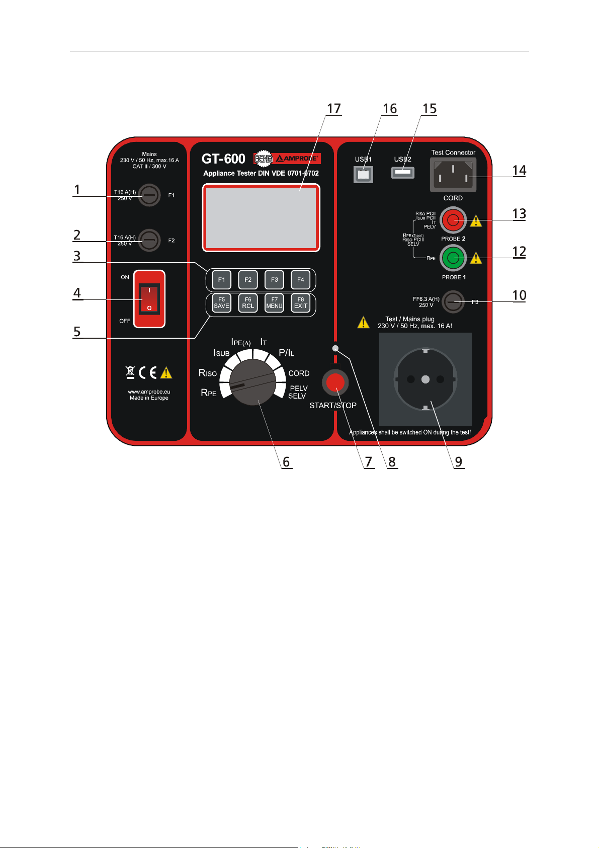
Front panel of the GT-600 Tester
Figure 1: Operational elements and connectors on GT-600 Tester
11
GT-600/GT-800 Instruction Manual
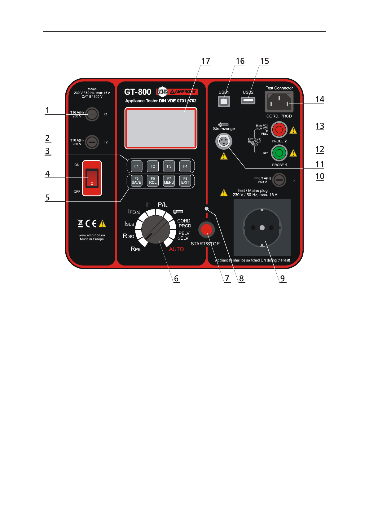
Front panel of the GT-800 Tester
Figure 2: Operational elements and connectors on GT-800 Tester
1 ....... Mains input fuse F1 T16 A (H) / 250 V, 5 × 20 mm
2 ....... Mains input fuse F2 T16 A (H) / 250 V, 5 × 20 mm
3 ....... Soft menu keys F1 ... F4
4 ....... ON/OFF mains switch with red pilot lamp
5 ....... Functional menu keys F4 ... F8, SAVE (to save test result), RCL (to recall
saved test result), MENU (to use menu functions) and EXIT (to exit current
menu level)
6 ....... Measurement function selector switch
7 ....... START/STOP button (to start or stop selected measurement function)
8 ....... ON red pilot lamp, measurement active
9 ....... Test/mains socket
10 ..... Fuse for RPE function F3 FF6.3 A (H) / 250 V, 5 × 20 mm
11 ..... CLAMP input connector (GT-800 only)
12 ..... Green test socket (PROBE 1)
13 ..... Red test socket (PROBE 2)
14 ..... IEC test socket (for CORD test and PRCD test)
15 ..... USB2 interface for USB barcode reader, keyboard or memory stick
16 ..... USB1 interface for PC
17 ..... Graphic LC-Display for measurement values, limit values and parameters.
12
GT-600/GT-800 Instruction Manual
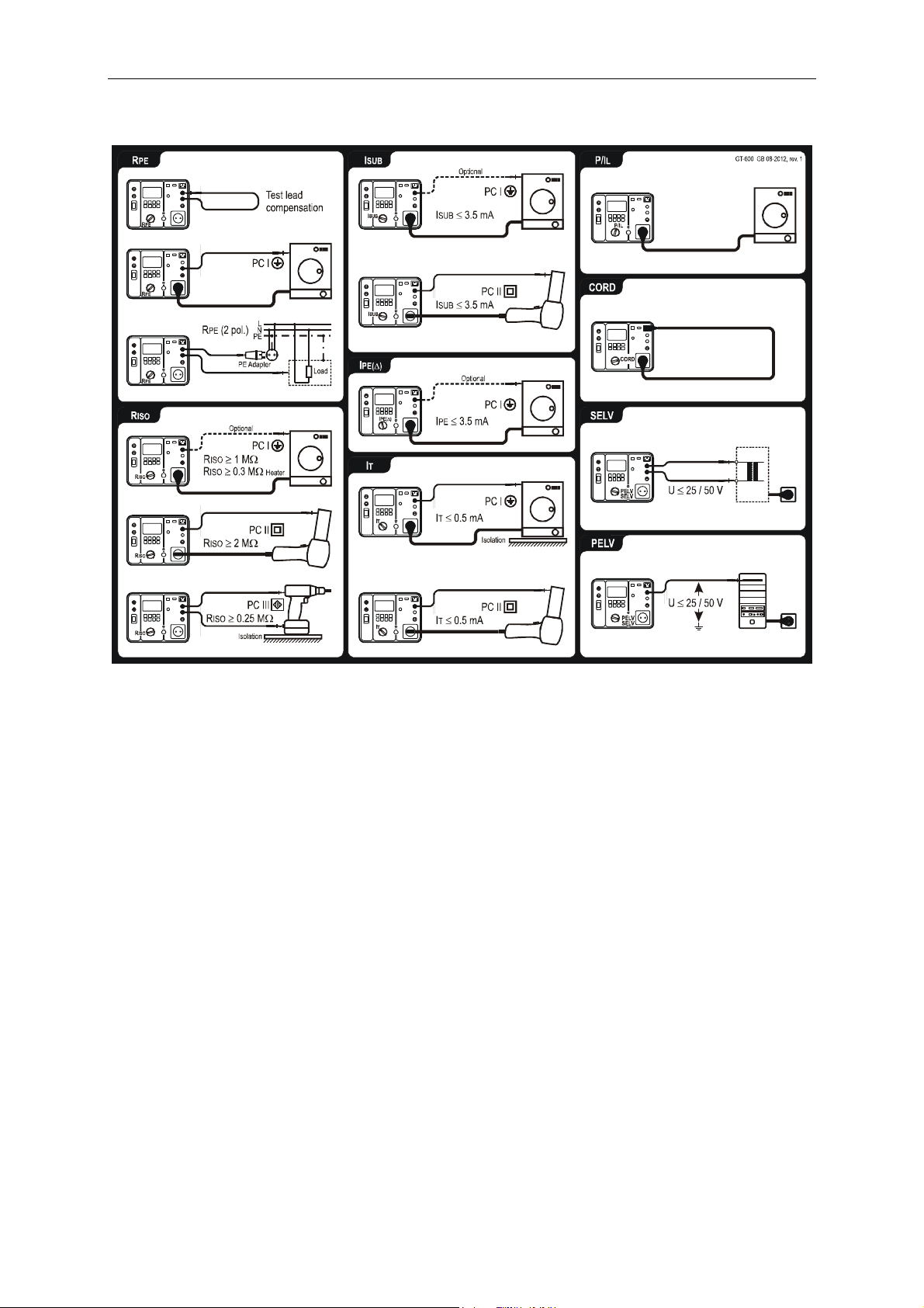
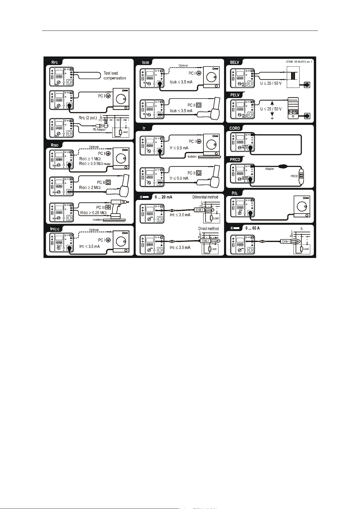
Cover of the GT-600 Tester, connection diagrams and limit values
Figure 3: Brief instructions with limit values (GT-600)
13
GT-600/GT-800 Instruction Manual
Cover of the GT-800 Tester, connection diagrams and limit values
Figure 4: Brief instructions with limit values (GT-800)
Measurement accessories are stored in the accessory bag on the top of the
tester.
14
GT-600/GT-800 Instruction Manual
Preparation of the GT-600/GT-800 Tester
Turning on the GT-600/GT-800 Tester
1) Connect the GT-600/GT-800 to a correctly installed Schuko mains socket.
2) Use the mains switch “ON/OFF“ (4) to turn on the GT-600/GT-800.
3) After turning on the GT-600/GT-800, pilot lamp of the power switch (4)
will switch on and the display (17) will show idle readout of selected
function. The GT-600/GT-800 is now ready for use.
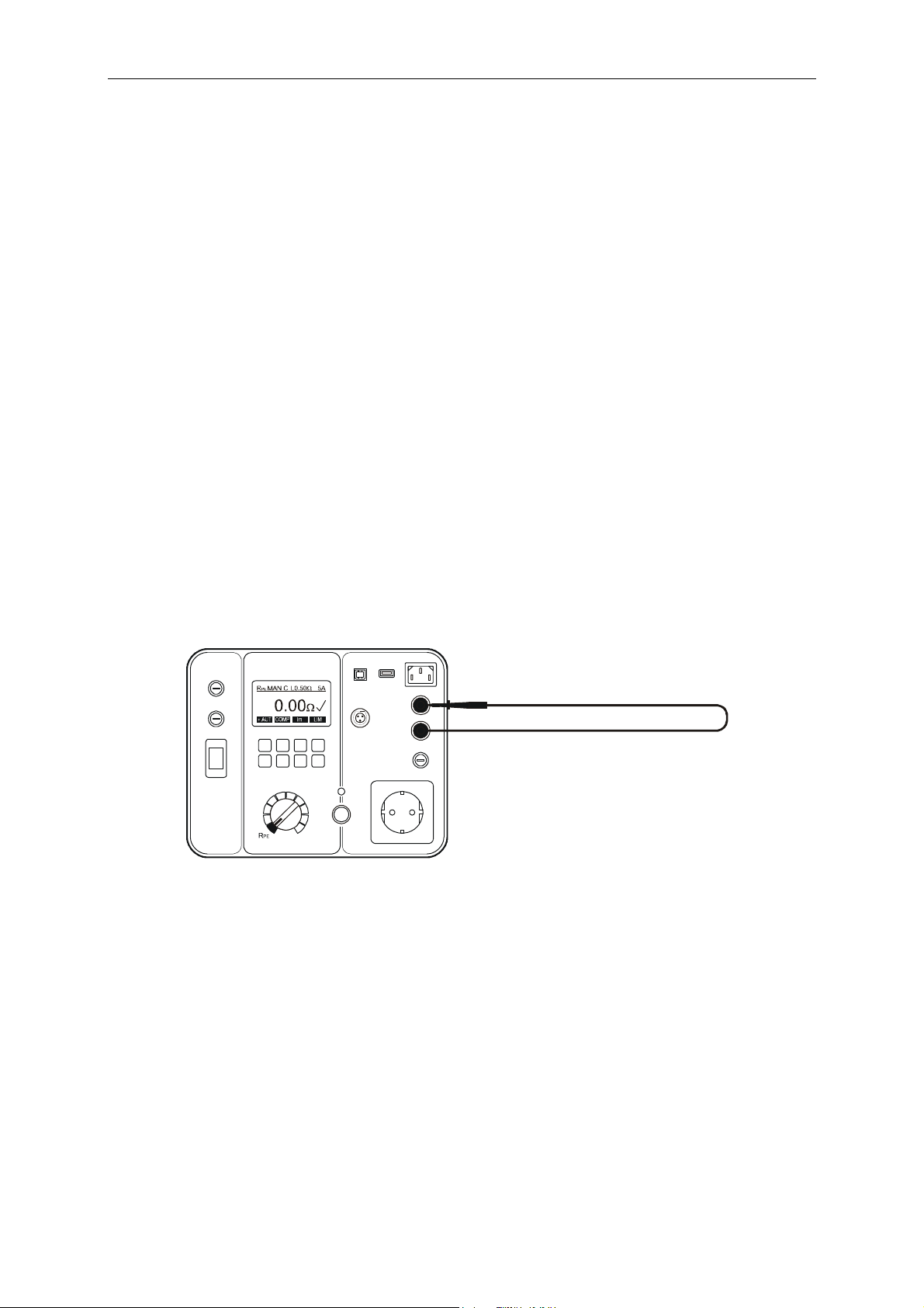
Test lead compensation
The GT-600/GT-800 appliance tester leaves the factory with uncompensated test
lead. We recommend to compensate test lead before starting the RPE tests,
otherwise result may not be correct and warning note “TEST LEAD NOT
COMPENSATED” will be displayed for a moment after pressing the “START” key.
1) Set the measurement function selector (6) to RPE position.
2) Connect test lead according to the figure below.
3) Press the “COMP” key (soft menu key F2) then start the measurement
by pressing the “START” button (7). Pilot lamp “ON” (8) indicates the
active measurement, then the result using uncompensated test lead is
displayed for a moment. Another regular measurement is done
automatically using compensated test lead, now the result should be
nearly zero. In the upper display line the character “C“ (Compensated)
appears as the information that test lead is compensated.
Figure 5: Connection for test lead compensation
☞ The compensation is used in all further RPE measurements. It will be
active even after switching off the GT-600/GT-800 appliance tester.
☞ The compensation is always carried out using test current of 5 A.
Cancel actual test lead compensation:
Open test loop (disconnect test lead from terminal PROBE 1 or PROBE 2) and
carry out the compensation as described above. The result >11.00 will be
displayed and “C” mark will disappear from the top display line.
15

GT-600/GT-800 Instruction Manual
Limit value setting
Limit value is offered in all functions except in P/IL and CLAMP. For limit value
setting press the “LIM” key (soft menu key F4) then use the soft menu keys “+”,
“–“, “STD” (Standard) or “CALC” (Calculation). The soft menu key F8 “EXIT” can
be used to exit limit value setting display.
☞ In case that test result comply with set limit value, the mark “ ” is
displayed and two short sound signals are present after finishing the
measurement. In case of non-compliance, the mark “X” is displayed and
one longer sound signal is present after finishing the measurement. The
limit value is saved as a parameter of the measurement result and is
transferred to PC in case of data transfer.
Start of the measurement
For single measurement press the START key and release it. In this case
measurement time is defined in MENU/SETUP/MEASUREMENT TIMES menu,
see the chapter “SETUP menu” on page 49. Watch elapsed time on displayed
bar graph during the measurement.
For continuous measurements press and keep pressing the START key for at
least 2 seconds until “CONT” (continuous) information is displayed.
Measurement time is limited to 5 minutes in this case. Continuous
measurement is available in all functions except in CORD, PRCD and AUTO
test.
External Voltage Display
If there is a dangerous external voltage present on test terminals prior to a
test or during it, the warning message “EXTERNAL VOLTAGE!“ will appear on
the display and the start of the measurement is blocked. Remove the external
voltage!
If an external voltage is applied to test terminals during the test in R
ISO
function, wrong measurement values may be displayed.
Please remove external voltage from any test terminal
immediately if “ EXTERNAL VOLTAGE!” warning is displayed.
Testing Appliances
WARNINGS
Before commencing any testing you are strongly advised to make reference to
the local regulations and standards for safety at works regulations and any
relevant publications from the Health and Safety Executive.
The appliance must be switched on for all tests.
When conducting tests do not touch the appliance as some tests involve high
voltages and high currents.
16

GT-600/GT-800 Instruction Manual
The tests should only be performed by competent persons who are familiar
with the requirements of the type of tests suitable for portable appliances.
It is potentially hazardous for both user and appliance should the wrong type
of tests be undertaken or if testing is carried out in an incorrect sequence.
It is important that you fully understand the various tests required and how
they should be performed.
The appliance must have passed the visual inspection, the protective bonding
resistance test (class I), and the insulation test (in this sequence) prior to any
other test. If any of these fail further testing must be stopped and any faults
must be rectified.
During the protective conductor current test, the touch current test and the
load test, the appliance will be energized at mains voltage. For this purpose,
switch on the appliance. Appliances driven by motors or equipped with
heating units may present a danger for the person testing (comply with the
appliance instruction manual!). Please ensure that the appliance is in a safe
condition to run and secure prior to testing.
Visual Inspection
Visually inspect the appliance before starting electrical tests.
Check the appliance for the following:
Condition of the appliance cables, i.e. no cuts, cracks or any physical damage
to the outer insulation layer.
Condition of the plug, cable securely attached, no signs of overheating and
that fitted fuses are correctly rated.
Any signs of damage, and that any mains or control switches will physically
switch on and off.
Any sockets for sign of overheating or physical damage.
17
GT-600/GT-800 Instruction Manual
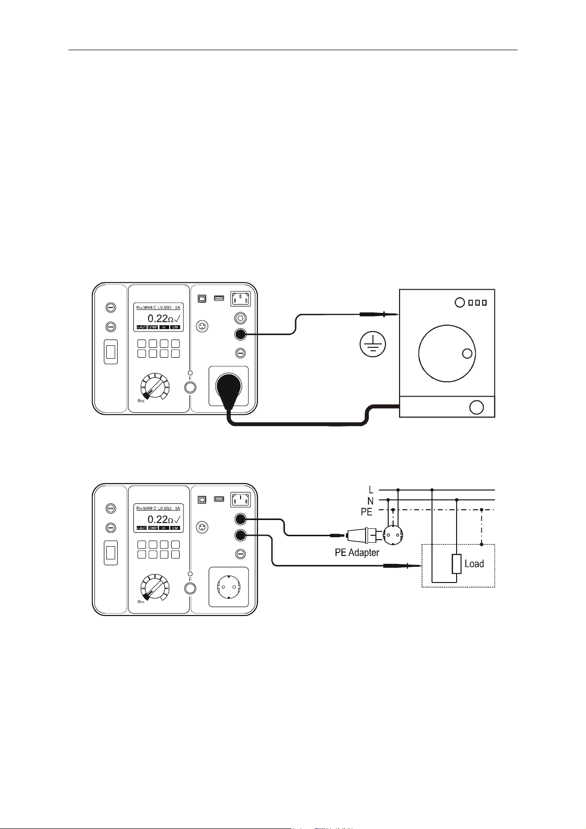
Protective Bonding Test 5 A / 0.2 A (RPE)
The protective bonding test measures the resistance between PE terminal of test
socket and PROBE 1 terminal. This test applies to class I appliances only.
Remarks:
To obtain correct protective bonding test results you must have
compensated (zeroed) the test lead, see the section “Test lead
compensation” on page 15.
Connect the appliance and the earth bond test lead according to the figure 6
or 7.
You should use the lower test current 0.2 A for certain appliances. Please
refer to local appliance test standards and guidance material.
During the measurement flex the flexible cord along its length to help find
any broken conductors or poor quality joints.
Figure 6: Protective bonding test connections at appliance with mains plug
Figure 7: Protective bonding test connections at permanently connected
appliance
18
GT-600/GT-800 Instruction Manual
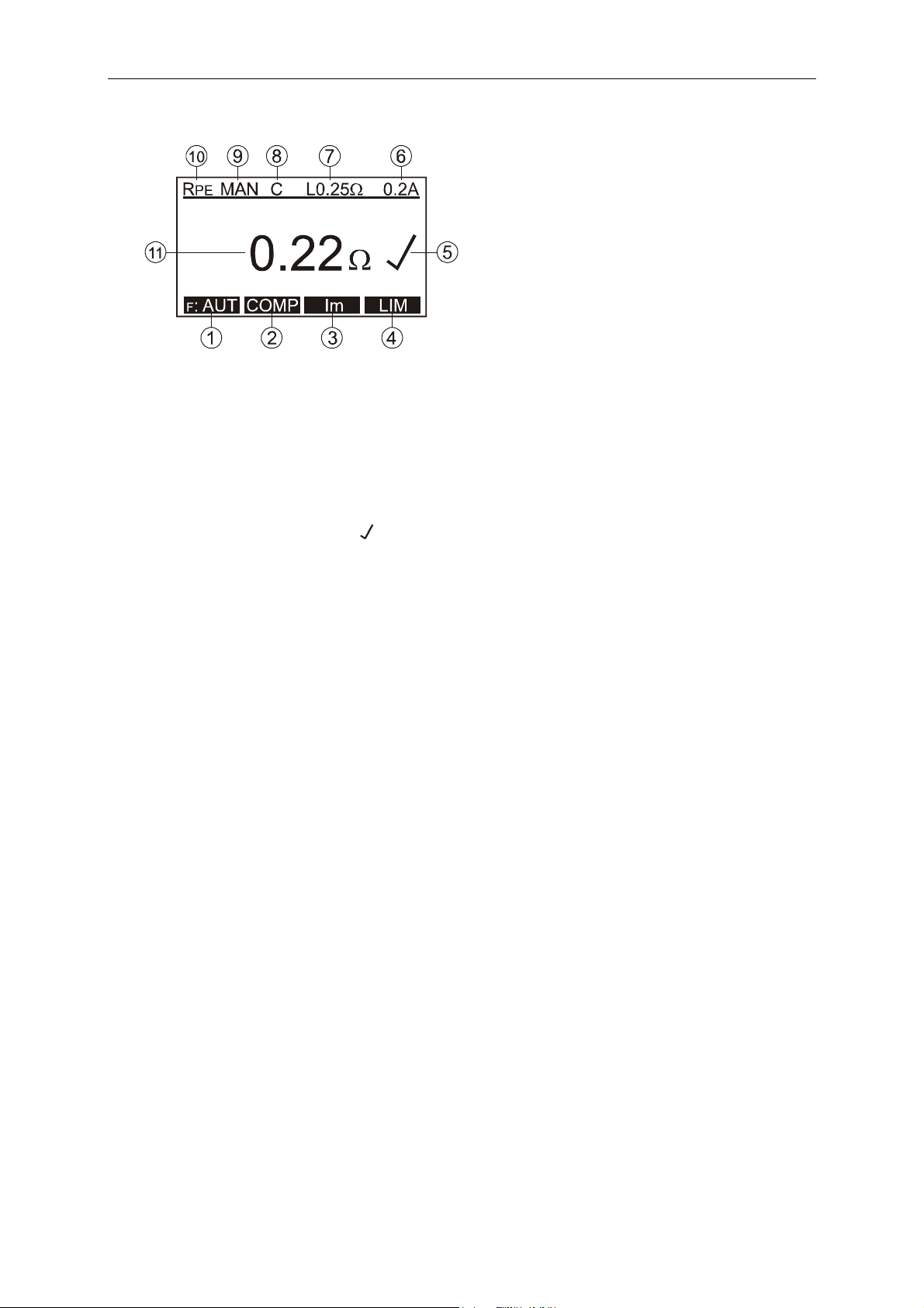
Display explanation:
Figure 8: Display in protective bonding test RPE
1 ...... “F: AUT” / “F: MAN” soft menu key, for selection of automatic /
manual start and store function.
2 ....... “COMP” soft menu key, for test lead compensation.
3 ...... “Im” soft menu key, for test current selection (0.2 A or 5 A).
4 ...... “LIM” soft menu key, for pass/fail limit value setting.
5 ...... Test result status ( ... result OK, X ... result not OK).
6 ...... Selected test current (0.2 A or 5 A).
7 ...... Pre-set pass/fail limit value.
8 ...... Test lead compensation mark (C ... compensated, blank .. not
compensated).
9 ...... Selected mode of start and save function (MAN, AUT).
MAN (Manual) ... Use START key to start the measurement.
AUT (Automatic) ... The test is started automatically after connecting
PROBE 1 to conductive part of tested appliance. Result is
automatically stored to last selected storage address. START key is not
active in this mode.
10 .... Function selected by the rotary switch (6).
11 .... Test result and unit.
Note:
In case that protective bonding test fails, the pass/fail limit value can be
recalculated by using the “LIM” and “CALC” keys and entering the length
and cross section of the mains lead. The last measurement value will be
deleted, and a new test has to be performed.
19
GT-600/GT-800 Instruction Manual
Pass/fail limit value calculation:
Cross section A Cable length L Limit value
5 m 0.3
5 ... 12.5 m 0.4
12.5 ... 20 m 0.5
1.5 mm2
20 ... 27.5 m 0.6
27.5 ... 35 m 0.7
35 ... 42.5 m 0.8
42.5 ... 50 m 0.9
50 m 1.0
2.5 ... 50 mm2 1 ... 50 m (res. 0.5 m)
RLIM = .L/A
Where:
... 0.01786 mm2/m (specific resistance of Cu)
L .. cable length in m
A .. cross section in mm2
Specific information that can be shown on the display:
Information displayed Description
TEST LEAD
NOT COMPENSATED
Test lead is not compensated (no “C” mark on
the display)! It is recommended to
compensate the test lead.
>5, NOT COMPENSATED
Compensation was not successfully done due
to too high compensation value (>5.00 )!
Test lead is wrong compensated (negative RPE
COMP?
result 0.05 ). Compensate the test lead
again.
External voltage is applied to one or more
test terminals, see the explanation in section
EXTERNAL VOLTAGE
“Pre-Tests and Protection, Functions and
Messages”.
Test lead is connected to PROBE 2. Reconnect
USE PROBE 1
>11.00 X
it to PROBE 1.
RPE value higher than 11.00 (over-range),
possibly because of open test lead.
In order to save displayed measurement result, press the “SAVE” function
key (F5) twice, for further instructions see the “Memorizing example”
section.
20
GT-600/GT-800 Instruction Manual
Insulation Resistance Test 250 V / 500 V (RISO)
The insulation resistance test measures the resistance of the insulation between:
L/N terminals of test socket and PE terminal of test socket in parallel with
PROBE 2 (at class I and class II). L/N terminals are shorted by the tester for this
test.
Test probe PROBE 1 and test probe PROBE 2 (at class III).
Warnings
The test voltage is either 500 V (or 250 Vd.c. at GT-800 only). Do not
touch the appliance during the insulation test! If the test fails, any metal
part of the appliance could become live!
Always make sure that the test has completed before disconnecting the
appliance leads to ensure that all capacitances have discharged!
Cautions
Do not perform the Insulation test on appliances that failed the
protective bonding test or the visual inspection test.
The insulation test may not be suitable for some types of appliances. For
these appliances an alternative test may be conducted such as touch
current, protective conductor current or substitute leakage current test.
It is essential to refer to the local appliance test standards and/or
reference material for the safe applicability of these alternative tests.
Test voltage of 500 V may not be suitable for some appliances that
contain overvoltage protection devices (e.g. varistors) in its installation.
For these appliances test voltage of 250 V shall be used, refer to the
local appliance test standards and/or follow the manufacturer
recommendations.
Remarks:
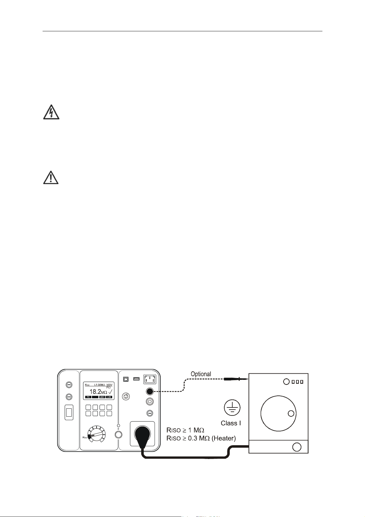
Connect the appliance and the test lead according to the figure 9, 10 or 11.
For class I appliances no probe is required except if there are some metal
parts on the appliance which are not connected to PE terminal.
For class II appliances apply the test probe to any exposed metalwork on the
appliance. Do the test for all exposed metal parts on the appliance, partial
results must pass pre-set limit value.
Figure 9: Insulation resistance test connections at appliance class I
21
GT-600/GT-800 Instruction Manual
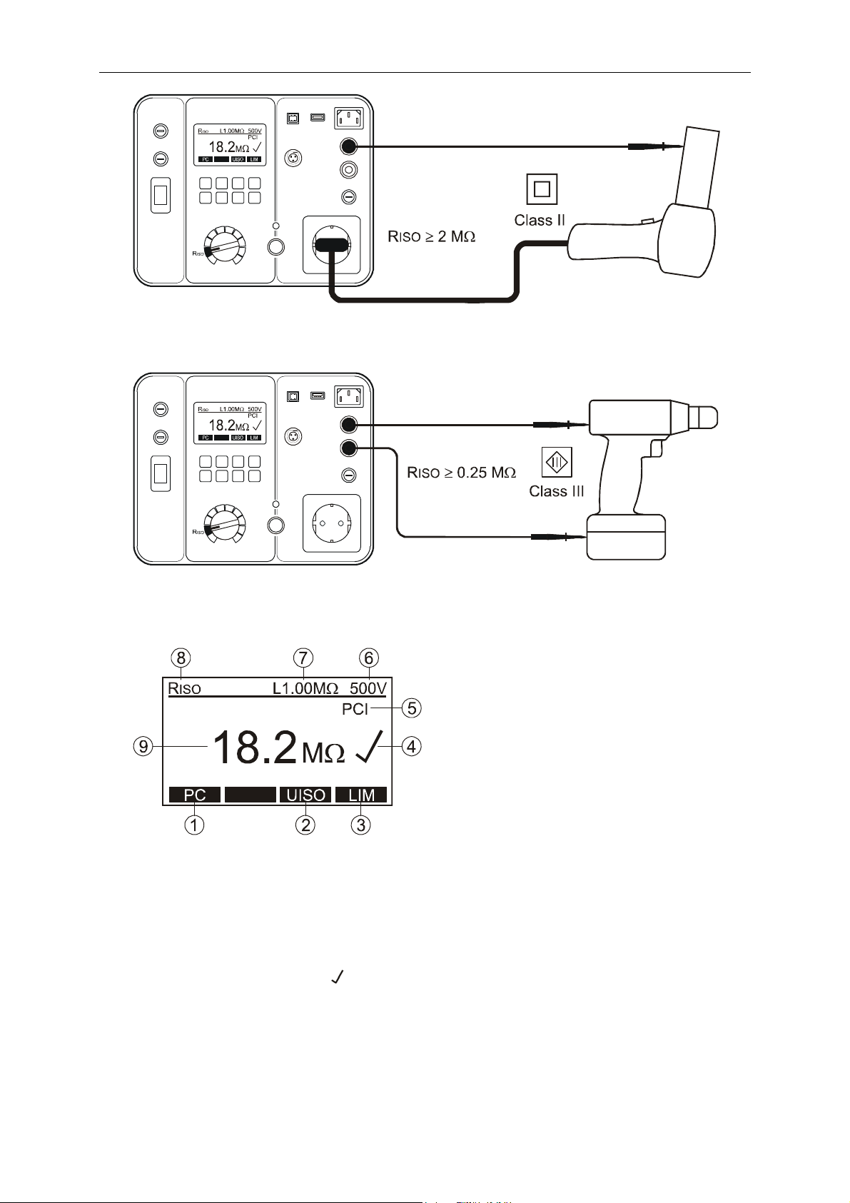
Figure 10: Insulation resistance test connections at appliance class II
Figure 11: Insulation resistance test connections at appliance class III
Display explanation:
Figure 12: Display in insulation resistance test RISO
1 ...... “PC” soft menu key, for selection of protection class (PC I-HEATER,
PC I, PC II or PC III).
2 ....... “UISO” soft menu key, for selection of test voltage (250 V or 500 V).
3 ...... “LIM” soft menu key, for pass/fail limit value setting.
4 ...... Test result status ( ... result OK, X ... result not OK).
5 ...... Selected protection class (PC I-HEATER, PC I, PC II or PC III).
6 ...... Selected test voltage 500 V (or 250 V at GT-800 only).
7 ...... Pre-set pass/fail limit value.
8 ...... Function selected by the rotary switch (6).
9 ...... Test result and unit.
22
GT-600/GT-800 Instruction Manual
Specific information that can be shown on the display
Information displayed Description
External voltage is applied to one or more
test terminals, see the explanation in section
EXTERNAL VOLTAGE
“Pre-Tests and Protection, Functions and
Messages”.
Test lead is connected to PROBE 1. Reconnect
USE PROBE 2
it to PROBE 2.
>100M
>20.0M
RISO value higher than 100 M (over-range).
Measurement range in class I / II is 100 M.
RISO value higher than 20.0 M (over-range).
Measurement range in class III is 20.0 M.
In order to save displayed measurement result, press the “SAVE” function
key (F5) twice, for further instructions see the “Memorizing example”
section.
23
GT-600/GT-800 Instruction Manual
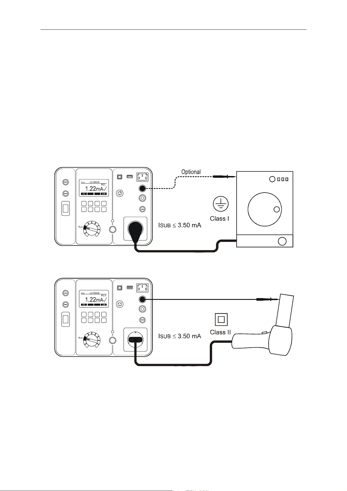
Substitute Leakage Current Test (ISUB)
The substitute leakage current test measures the leakage current between L/N
terminals of test socket and PE terminal of test socket in parallel with PROBE 2
(at class I, class II). L/N terminals are shorted by the tester for this test.
It is essential to refer to the local appliance test standards and/or guidance
material for the safe applicability of this test.
Remarks:
Connect the appliance and the test lead according to the figure 13 or 14.
For class I appliances no probe is required except if there are some metal
parts on the appliance not connected to PE terminal.
For class II appliances apply the test probe to any exposed metalwork on the
appliance. Do the test for all exposed metal parts on the appliance.
Figure 13: Substitute leakage current test connections at appliance class I
Figure 14: Substitute leakage current test connections at appliance class II
24

GT-600/GT-800 Instruction Manual
Display explanation:
Figure 15: Display in substitute leakage current test ISUB
1 ...... “PC” soft menu key, for selection of protection class (PC I or PC II).
2 ...... “LIM” soft menu key, for pass/fail limit value setting.
3 ...... Test result status ( ... result OK, X ... result not OK).
4 ...... Selected protection class (PC I or PC II).
5 ...... Pre-set pass/fail limit value.
6 ...... Function selected by the rotary switch.
7 ...... Test result and unit.
Specific information that can be shown on the display
Information displayed Description
External voltage is applied to one or more
test terminals, see the explanation in section
EXTERNAL VOLTAGE
“Pre-Tests and Protection, Functions and
Messages”.
Test lead is connected to PROBE 1. Reconnect
USE PROBE 2
it to PROBE 2.
>20.0mA X ISUB result >20.0mA (over-range).
In order to save displayed measurement result, press the “SAVE” function
key (F5) twice, for further instructions see the “Memorizing example”
section.
25

GT-600/GT-800 Instruction Manual
Protective Conductor Current Test (IPE())
The protective conductor current test measures the earth leakage current in the
protective conductor (PE) of appliances connected to the test/mains socket of the
GT-600/GT-800. The measurement is carried out by the differential method.
Warning
NEVER carry out this test unless you have first carried out a thorough
visual inspection followed by a test of the protective bonding resistance
(for class I appliances), and then a test of insulation resistance. You must
verify that these tests have passed before engaging the protective
conductor current test.
Caution
Live test! The appliance will be energized at mains voltage. For this
purpose switch on the appliance. Appliances driven by motors or
equipped with heating units may present a danger for the person
testing (comply with the appliance instruction manual!). Ensure that the
appliance is in a safe condition to run and secure it prior to testing.
Remarks:
Connect the appliance according to the figure 16.
If the protective conductor current is higher than 20.00 mA for 2 seconds,
the test will be interrupted automatically and “RANGE OVERLOAD” message
will be displayed.
The measurement must be performed in both positions of the mains plug,
the greater of the two values obtained must be used.
Figure 16: Protective conductor current test connections
26

GT-600/GT-800 Instruction Manual
+
Display explanation:
Figure 17: Display in protective conductor current test IPE
1 ...... “POL” soft menu key, for selection of mains voltage polarity (GT-800
only).
2 ...... “LIM” soft menu key, for pass/fail limit value setting.
3 ...... Test result status (
... result OK, X ... result not OK).
4 ...... Selected mains polarity (GT-800 only).
... phase connected to the right terminal of test socket.
... phase connected to the left terminal of test socket.
5 ...... Pre-set pass/fail limit value.
6 ...... Function selected by the rotary switch.
7 ...... Test result and unit.
Specific information that can be shown on the display
Information displayed Description
External voltage is applied to one or more
test terminals, see the explanation in section
EXTERNAL VOLTAGE
“Pre-Tests and Protection, Functions and
Messages”.
Test lead is connected to PROBE 1.
USE PROBE 2
MAINS SWITCH ON
CONTINUE?
Reconnect it to PROBE 2.
Warning! Mains voltage will be applied to
test/mains socket after confirming this
message!
Note! No device is connected to test/mains
NO DEVICE
socket, or mains switch on device is not
switched ON!
>20.00mA X
IPE current higher than 20.00 mA (overrange).
In order to save displayed measurement result, press the “SAVE” function
key (F5) twice, for further instructions see the “Memorizing example”
section.
27

GT-600/GT-800 Instruction Manual
Touch Current Test (IT)
The touch current test measures the leakage current from exposed conductive
parts of tested appliance via test probe PROBE 2 and internal resistance of
approx. 2 k to earth. The device under test is not necessary to be connected to
the test/mains socket of the GT-600/GT-800, it can be also externally powered.
The measurement is carried out by the direct method.
Warning
NEVER carry out this test unless you have first carried out a thorough
visual inspection, followed by a test of the protective bonding resistance
(for class I appliances), and then a test of insulation resistance. You must
verify that these tests have passed before engaging the touch current
test.
Caution
Live test! The appliance will be energized at mains voltage. For this
purpose, switch on the appliance. Appliances driven by motors or
equipped with heating units may present a danger for the person
testing (comply with the appliance instruction manual!). Ensure that the
appliance is in a safe condition to run and secure it prior to testing.
Remarks:
Connect the appliance and the test lead according to the figure 18 or 19.
For class I appliances apply the test probe to any metal part not connected to
PE terminal.
For class II appliances apply the test probe to any exposed metalwork on the
appliance.
If the touch current is higher than 2.00 mA for 2 seconds, the test will be
interrupted automatically and “RANGE OVERLOAD” message will be
displayed.
The measurement must be performed in both positions of the mains plug,
the greater of the two values obtained must be used.
Figure 18: Touch current test connections at appliance class I
28

GT-600/GT-800 Instruction Manual
Figure 19: Touch current test connections at appliance class II
Display explanation:
Figure 20: Display in touch current test IT
1 ...... “POL” soft menu key, for selection of mains voltage polarity (GT-800
only).
2 ...... “LIM” soft menu key, for pass/fail limit value setting.
3 ...... Test result status (
4 ...... Selected mains polarity (GT-800 only).
+ ... phase connected to the right terminal of test socket,
... phase connected to the left terminal of test socket.
5 ...... Pre-set pass/fail limit value.
6 ...... Function selected by the rotary switch.
7 ...... Test result and unit.
... result OK, X ... result not OK).
29
GT-600/GT-800 Instruction Manual
Specific information that can be shown on the display
Information displayed Description
External voltage is applied to one or more
test terminals, see the explanation in
EXTERNAL VOLTAGE
section “Pre-Tests and Protection,
Functions and Messages”.
MAINS SWITCH ON
CONTINUE?
Warning! Mains voltage will be applied to
test/mains socket after confirming this
message!
Note! No device is connected to test/mains
NO DEVICE
socket, or mains switch on device not
switched ON!
Test lead is connected to PROBE 1.
USE PROBE 2
Reconnect it to PROBE 2.
>2.00mA X IT value higher than 2.00 mA (over-range).
Voltage higher than 50 V approx. is
VOLTAGE OVER RANGE
present on PROBE 2. Remove the voltage.
Current higher than 2 mA was flowing to
CURRENT OVER RANGE
test probe for 2 seconds.
In order to save displayed measurement result, press the “SAVE” function
key (F5) twice, for further instructions see the “Memorizing example”
section.
30

GT-600/GT-800 Instruction Manual
Power, Load Current Test (P/IL)
The power/load current test measures the apparent power S, active power PA,
mains voltage ULN, load current IL and power factor PF of the appliance,
connected to mains test/mains socket.
Warning
NEVER carry out this test unless you have first carried out a thorough
visual inspection, followed by a test of the protective bonding resistance
(for class I appliances), and then a test of insulation resistance and
protective conductor current or touch leakage test. You must verify that
these tests have passed before engaging this test.
Caution
Live test! The appliance will be energized at mains voltage. For this
purpose, switch on the appliance. Appliances driven by motors or
equipped with heating units may present a danger for the person
testing (comply with the appliance instruction manual!). Ensure that the
appliance is in a safe condition to run and secure it prior to testing.
Remarks:
Connect the appliance according to the figure 21.
If the load current is higher than 18.0 A for 10 seconds, the test will be
interrupted automatically and “RANGE OVERLOAD” message will be
displayed.
Figure 21: Power / Load current test connection
31
GT-600/GT-800 Instruction Manual
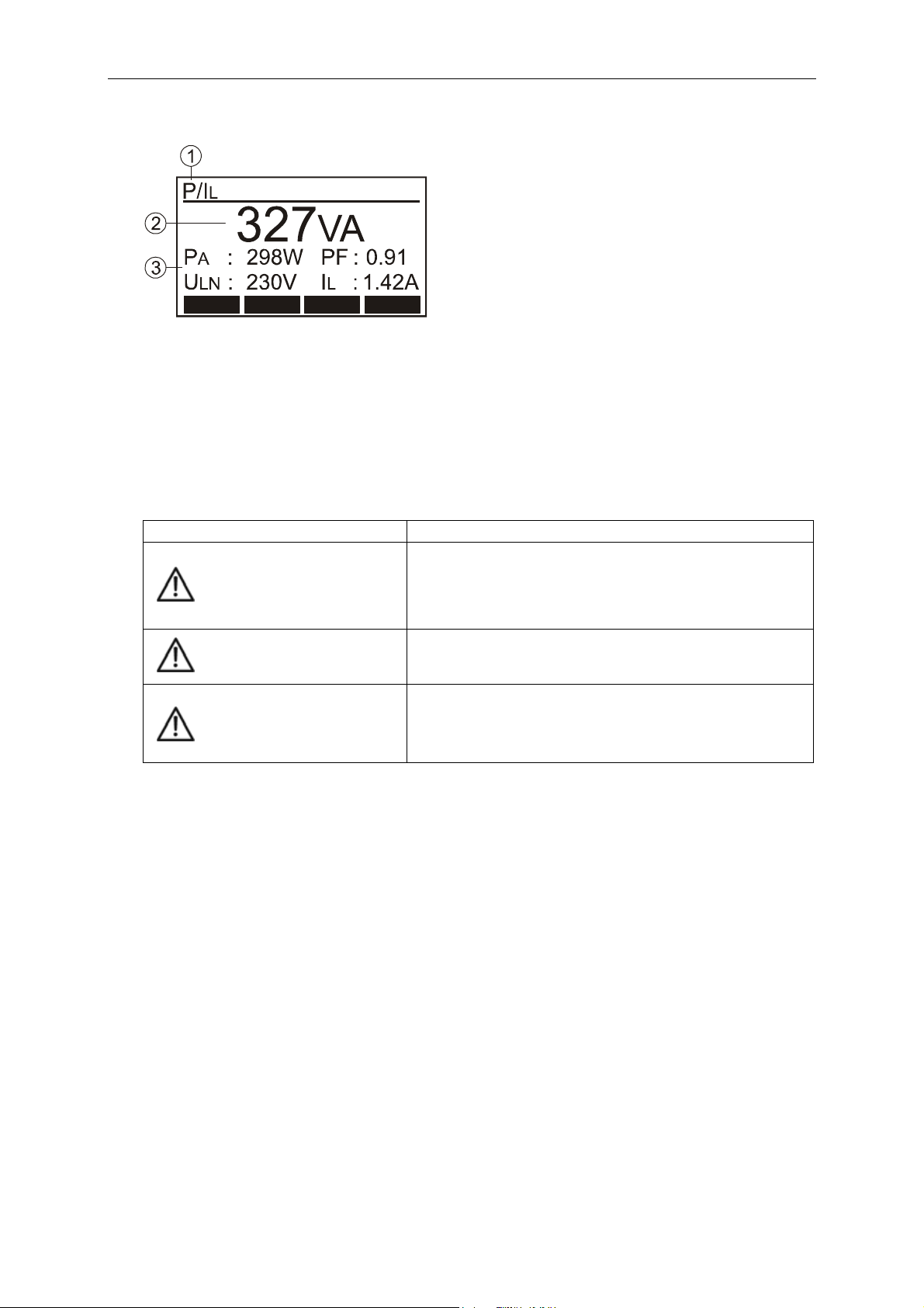
Display explanation:
Figure 22: Display in power / load current test P/IL
1 ...... Function selected by the rotary switch.
2 ...... Main result (apparent power in VA).
3 ...... Sub-results (active power PA in W, mains voltage ULN in V, power
factor PF and load current I
L in A)
Specific information that can be shown on the display
Information displayed Description
External voltage is applied to one or more
test terminals, see the explanation in section
EXTERNAL VOLTAGE
“Pre-Tests and Protection, Functions and
Messages”.
Test lead is connected to PROBE 1 or to
DO NOT USE PROBES
MAINS SWITCH ON
CONTINUE?
PROBE 2. Disconnect it.
Warning! Mains voltage will be applied to
test/mains socket after confirming this
message!
In order to save displayed measurement result, press the “SAVE” function
key (F5) twice, for further instructions see the “Memorizing example”
section.
32

GT-600/GT-800 Instruction Manual
Clamp Current Test ( ) (GT-800 only)
The test with the external clamp adapter measures the current in clamped
conductor. The function is intended to measure:
The protective conductor current (earth leakage current) in the protective
conductor (PE).
The load current in line (or neutral) conductor.
Remarks:
Connect the clamp according to the figure 23, 24 or 25.
Select appropriate measurement range by using soft menu key “RNG” (F1)
(0 ... 20 mA for leakage current or 0 ... 60 A for load current).
Figure 23: Protective conductor current test connection (differential method)
Figure 24: Protective conductor current test connection (direct method)
33

GT-600/GT-800 Instruction Manual
Figure 25: Load current test connection
Display explanation:
Figure 26: Display in CLAMP current test ( )
1 ...... “RNG” soft menu key, for selection of measurement range (0...20 mA
or 0...60 A).
2 ...... Selected measurement range.
3 ...... Function selected by the rotary switch.
4 ...... Test result and unit.
In order to save displayed measurement result, press the “SAVE” function
key (F5) twice, for further instructions see the “Memorizing example”
section.
34

GT-600/GT-800 Instruction Manual
IEC CORD Test (CORD/PRCD)
The IEC CORD test does a full test of IEC cords, extension leads and cable reels.
Following parameters are tested and measured:
Protective bonding resistance RPE
Insulation resistance RISO between PE and L/N conductors (L/N conductors are
shorted by the GT-600/GT-800 Tester)
L conductor continuity
N conductor continuity
L and N condition (OK/shorted).
CORD
Figure 27: CORD test connection
Display explanation:
Figure 28: Display in CORD test
1 ...... “TYPE” soft menu key, for selection of measurement function (CORD
or PRCD).
2 ....... “COMP” soft menu key, for lead compensation of test adapter.
3 ...... “LIM” soft menu key, for pass/fail limit value setting of protective
bonding.
4 ...... Test result status (
... result OK, X ... result not OK).
5 ...... Used test current 5.0 A (fixed parameter).
6 ...... Pre-set pass/fail limit value for protective bonding RPE.
7 ...... Function selected by the rotary switch and the “TYPE” key.
8 ...... Test parameters, set limit values, test results and units.
35

GT-600/GT-800 Instruction Manual
Procedure to test a mains cable extension leads or cable reels:
1) Use a standard IEC cable as a test adapter to connect tested mains
extension coupling to IEC connector (14) of the GT-600/GT-800 Tester.
2) Compensate the test adapter:
Connect the test adapter according to the figure 27 first and press the
“COMP” key and then START key. Compensation will be done then
another measurement will follow to show the efficiency of the
compensation.
3) Connect the mains extension or cable reel to be tested via the
compensated test adapter to GT-600/GT-800 according to the figure
below. Carry out the measurement by pressing the START key.
Figure 29: Cable reel or extension cable test connection
Cancel actual test lead compensation:
Remove any cable from IEC connector (14) and carry out the compensation.
Result >11.00 will be displayed and “C” mark will disappear from the top
display line.
Specific information that can be shown on the display
Information displayed Description
External voltage is applied to one or more
test terminals, see the explanation in section
EXTERNAL VOLTAGE
“Pre-Tests and Protection, Functions and
Messages”.
Test lead is connected to PROBE 1 or to
DO NOT USE PROBES
PROBE 2. Disconnect it.
In order to save displayed measurement result, press the “SAVE” function
key (F5) twice, for further instructions see the “Memorizing example”
section.
36

GT-600/GT-800 Instruction Manual
PRCD Test (CORD/PRCD) (GT-800 only)
The PRCD test function of the GT-800 does a full test of PRCD 2-pole, 3-pole and
type S (AC types).
Following parameters are tested and measured:
Visual test
Confirm pass of visual test by the soft menu key “YES”.
Protective bonding continuity R
PE
The measurement is carried out by using test current of 5 A (fixed
parameter). The limit value for R
PE is adjustable by using the soft menu key
“LIM” in idle display mode. Also the limit value can be calculated on bases of
entered cross section and length of the PRCD cable.
Insulation resistance RISO
The insulation resistance is measured on the output side of the PRCD at open
PRCD switch by using test voltage of 500 V (fixed parameter). The limit value
for RISO is fixed and pre-set to 1.00 M.
Protective conductor current IPE
The measurement is done in two steps (two mains voltage polarities). The
polarity is exchanged automatically. The limit value for IPE is fixed and preset to 3.50 mA.
Functionality of the TEST button
After pressing the TEST button of the RCD, both L and N conductors must be
switched off from mains by the PRCD switch. The test result is displayed as
OK or FAILED.
Functional test at L disconnection
The GT-800 disconnects input L terminal, then both L and N conductors must
be switched off from mains by the PRCD switch. The test result is displayed as
OK or FAILED.
Functional test at N disconnection
The GT-800 disconnects input N terminal, then both L and N conductors must
be switched off from mains by the PRCD switch. The test result is displayed as
OK or FAILED.
Trip out time at IN/2
PRCD must not trip at this current, max. measurement time/range is 300 ms.
Trip out time at IN
PRCD must trip within 300 ms.
Trip out time at 5×IN
PRCD must trip within 40 ms.
Tripping current I
The test is carried out by using a ramp current starting at 0.5 IN and
increasing the test current by 0.05×IN per step up to IN. There are 11 test
steps, duration 300 ms per step, pause duration is 30 ms.
Trip out time at tripping current t/ I
The test is done in previous step, limit value is 300 ms.
37

GT-600/GT-800 Instruction Manual
Figure 30: PRCD test connection
Display explanation:
Figure 31: Display in PRCD test
1 ...... “ ” soft menu key, to move the cursor down when checking test
sub-results.
2 ...... “ ” soft menu key, to move the cursor up when checking test sub-
results.
3 ...... Test result status ( ... results OK, X ... results not OK).
4 ...... Selected nominal differential current IN (10 mA or 30 mA).
5 ...... Pre-set pass/fail limit value for protective bonding R
PE.
6 ...... Function selected by the rotary switch and the “TYPE” key.
7 ...... Test parameters, test results and units.
38

GT-600/GT-800 Instruction Manual
Specific information that can be shown on the display
Information displayed Description
External voltage is applied to one or more
test terminals, see the explanation in section
EXTERNAL VOLTAGE
“Pre-Tests and Protection, Functions and
Messages”.
Test lead is connected to PROBE 1 or to
DO NOT USE PROBES
PROBE 2. Disconnect it.
MAINS SWITCH ON
CONTINUE?
Warning! Mains voltage will be applied to
test socket after confirming this message!
ISUB > 3.50 mA
Substitute leakage current is higher than
3.50 mA. Dangerous, check the appliance!
There was no action (no key pressed) for
TIME OUT
more than 1 minute (repeat the test from
the beginning) or the PRCD is faulty.
PRCD ON Switch on PRCD
In order to save displayed measurement result, press the “SAVE” function
key (F5) twice, for further instructions see the “Memorizing example”
section.
39

GT-600/GT-800 Instruction Manual
Protective Extra Low Voltage Test (PELV)
The test measures the protective extra low voltage between any accessible
conductive part of tested appliance and earth (PE).
Figure 32: PELV test connection
Display explanation:
Figure 33: Display in PELV test
1 ...... “SELV/PELV” soft menu key, for selection of measurement function
(SELV or PELV).
2 ...... “LIM” soft menu key, for pass/fail limit value setting (standard values
are 25 or 50 V).
3 ...... Test result status (
... result OK, X ... result not OK).
4 ...... Pre-set pass/fail limit value.
5 ...... Function selected by the rotary switch and the “SELV/PELV” key.
6 ...... Test result and unit.
Specific information that can be shown on the display
Information displayed Description
<10.0V PELV value lower than 10.0 V.
>150.0V
PELV value higher than 150.0 V. Remove the
voltage.
In order to save displayed measurement result, press the “SAVE” function
key (F5) twice, for further instructions see the “Memorizing example”
section.
40

GT-600/GT-800 Instruction Manual
Safety Extra Low Voltage Test (SELV)
The test measures the safety extra low voltage between two accessible
conductive parts of tested appliance.
Figure 34: SELV test connection
Display explanation:
Figure 35: Display in SELV test
1 ...... “PELV/SELV” soft menu key, for selection of measurement function
SELV or PELV).
2 ...... “LIM” soft menu key, for pass/fail limit value setting (standard values
are 25 or 50 V).
3 ...... Test result status (
... result OK, X ... result not OK).
4 ...... Pre-set pass/fail limit value.
5 ...... Function selected by the rotary switch and the “SELV/PELV” key.
6 ...... Test result and unit.
Specific information that can be shown on the display
Information displayed Description
<10.0V SELV value lower than 10.0 V.
>150.0V
SELV value higher than 150.0 V. Remove the
voltage.
In order to save displayed measurement result, press the “SAVE” function
key (F5) twice, for further instructions see the “Memorizing example”
section.
41

GT-600/GT-800 Instruction Manual
AUTO Test (GT-800 only)
This is most common used test mode as it leads the operator through the whole
test procedure. There are 13 factory-programmed Auto-Tests and free space for
additional 17 customer-created ones.
Factory-programmed Auto-Tests for class I appliances (GERMAN REGION)
(listed figures are limit values in each test)
Tests 145 146 147 148 149 150 151 160 161
Visual Inspection Yes Yes Yes Yes Yes Yes Yes Yes Yes
Protective bonding
resistance 200 mA ()
Protective bonding
resistance 5 A ()
Insulation resistance 500 V
(M)
Substitute leakage current
(mA)
Protective conductor
current (mA)
0.30 - 0.30 0.30 0.30 - - - -
- 0.3 - - - 0.3 1.00 - -
1.00 1.00 0.30 - - 1.00 1.00 1.00 1.00
- - 3.50 - - 3.50 3.50 - -
3.50 3.50 - 3.50 3.50 - - 3.50 3.50
Touch current (mA) - - - - 0.50 - - - 0.50
Apparent power (kVA) 3.7 3.7 - 3.7 3.7 - - 3.7 3.7
Factory-programmed Auto-Tests for class II appliances (GERMAN REGION)
(listed figures are limit values in each test)
Tests 241 242 243 244
Visual Inspection Yes Yes Yes Yes
Protective bonding
resistance 200 mA ()
Protective bonding
resistance 5 A ()
Insulation resistance 500 V
(M)
Substitute leakage current
(mA)
Protective conductor
current (mA)
- - - -
- - - -
2.00 2.00 - -
- 0.50 - -
- - - 0.50
Touch current (mA) 0.50 - 0.50 Apparent power (kVA) 3.7 - 3.7 3.7
42

GT-600/GT-800 Instruction Manual
Factory-programmed Auto-Tests for class I appliances (ENGLISH REGION)
(listed figures are limit values in each test)
Tests 131 132 133 134 135 136 137
Visual Inspection Yes Yes Yes Yes Yes Yes Yes
Protective bonding
resistance 200 mA ()
Protective bonding
resistance 5 A ()
Insulation resistance 500 V
(M)
Substitute leakage current
(mA)
Protective conductor
current (mA)
- - 0.10 0.10 - 0.1 -
0.1 0.1 - - 0.1 - -
1.00 1.00 1.00 1.00 1.00 1.00 1.00
- - - - - - -
3.50 0.75 3.5 0.75 - - 3.50
Touch current (mA) - - - - - - Apparent power (kVA) 3.0 3.0 3.0 3.0 - - 3.7
Factory-programmed Auto-Tests for class II appliances (ENGLISH REGION)
(listed figures are limit values in each test)
Tests 231 232 233 234
Visual Inspection Yes Yes Yes Yes
Protective bonding
resistance 200 mA ()
Protective bonding
resistance 5 A ()
Insulation resistance 500 V
(M)
Substitute leakage current
(mA)
Protective conductor
current (mA)
- - - -
- - - -
2.00 2.00 2.00 2.00
- - - -
- - - 0.25
Touch current (mA) 0.25 0.25 - Apparent power (kVA) 3.0 - - 3.0
Note: AUTO-Test numbers 301 up to 317 are reserved for customer-created
AUTO Tests.
43

GT-600/GT-800 Instruction Manual
Idle display explanation:
Figure 36: Idle display in AUTO function
1 ...... “
” soft menu key, to move the cursor down in order to check the set of
tests to be done.
2 ...... “
” soft menu key, to move the cursor up in order to check the set of
tests to be done.
3 ...... “A
” soft menu key, to select appropriate AUTO Test (decreasing the
AUTO Test number).
4 ...... “A
” soft menu key, to select appropriate AUTO Test (increasing the
AUTO Test number).
5 ...... Protection class of selected AUTO Test.
6 ...... Appliance/AUTO-Test description.
7 ...... Number of selected AUTO Test.
8 ...... Tests, test parameters and limit values.
Test procedure:
- Select AUTO Test mode by using the rotary switch (6), idle display will
appear.
- Select appropriate AUTO Test by using the “A
” and “A ” soft menu
keys.
- Connect the appliance and test leads as required by the first test, e.g. R
(see the instructions for individual tests).
- Press the START key, visual inspection will be required.
- Do the visual inspection (see the section “Visual Inspection”). If the visual
test passes, confirm the action by pressing the “YES” soft menu key then
the next test is offered e.g. RPE.
- Connect test lead to the first accessible conductive part and press the
“START” key, measurement is carried out and test result is displayed.
- Repeat the test for all accessible conductive parts, then press the “NEXT”
key in order to move to the next test e.g. RISO. The worst RPE test result
(the highest) is displayed, ready for later memorizing.
- Do all tests required by selected AUTO Test following the same procedure
as for the first test.
- Press the “END” soft menu key after finishing all tests, display turns to
“check” mode, you may check all sub-results (worst result in each
function) by using the “
” and “ ” soft menu keys.
44
PE

GT-600/GT-800 Instruction Manual
R
T
K
In order to save displayed measurement results, press the “SAVE” function
key (F5) twice, for further instructions see the “Memorizing example”
section.
During the AUTO Test procedure the following soft menu keys can be offered:
IGN
Pressing the “IGNR” (Ignore) menu key the operator will ignore current
test result (for example, if it was carried out by mistake, or if it is out of
prescribed limit value).
Note! After pressing the “IGNR” menu key, previous worst result will be
displayed.
DEL
Pressing the “DEL” (Delete) menu key the operator will delete worst
result (for example, if current result was already ignored by pressing the “IGNR”
menu key).
Note! Be aware there will be no result available any more after pressing the
“DEL” menu key.
NEX
Pressing the “NEXT” menu key the operator will move to the next test
(for example from RPE to RISO test).
BAC
Pressing the “BACK” menu key the operator will move back to previous
test (for example from RISO to RPE test).
END
Pressing the “END” menu key the operator will end the AUTO Test
procedure and move to “check” mode. After pressing the “END” menu key you
may check all sub-results (worst result in each function) by using the “ ” and
“ ” soft menu keys.
45

GT-600/GT-800 Instruction Manual
Menu Functions
For further selections, entry and display of instrument’s settings, press the
“MENU” function key (F7), the following selection menu appears.
Figure 37: “Menu” display
1 ....... “▼” menu key (down) to move the cursor down
2 ....... “▲” menu key (up) to move the cursor up
3 ....... “ “ menu key (Enter)
4 ....... Selected menu function
5 ....... Other available menu functions
General operation instructions
Use the “▼” and “▲” menu keys to select desired menu function, then
confirm it by pressing the “” menu key.
Entered menu function may be aborted by pressing the “EXIT” function key
(F8).
By pressing the “” menu key the selected function will be activated.
46

GT-600/GT-800 Instruction Manual
MEMORY Menu
In this menu the following selections are available:
SAVE TO USB: Transfer of stored data to USB memory stick. The whole
storage (TOTAL), individual clients (CLI), individual
appliances (APP) or only individual measurement results
(0001) can be transferred. Data records to be transferred
can be selected by using the “◄”, “►” and “▼” menu
keys, transfer action must be confirmed by pressing the
“” menu key.
USB memory stick shall be connected to USB interface
USB2. Three sound signals will follow after plugging it to
USB2 connector as a confirmation the memory stick is
recognized by the GT-600/GT-800 Tester.
Note! The USB memory stick has to be FAT12, FAT16 or FAT32 formatted, sector
size 512 Byte.
CLEAR MEMORY: Erasing of measurement results. The whole memory
(TOTAL), individual clients (CLI), individual appliances
(APP) or only individual measurement results (0001) can
be erased. Data records to be erased can be selected by
using the “◄”, “►” and “▼” menu keys, the clear action
must be confirmed by pressing the “” menu key.
There is another possibility to clear only results under
selected address or to clear the results including selected
address.
MEMORY PROPERTY: Number of occupied/total available memory locations
(LOCATIONS), number of stored results (RESULTS) and
number of entered appliances / total available number of
appliances (200) (APPLIANCES) is displayed.
The results are written in a file that can be read by the optional software es
control.
OPERATOR Menu
Modify or enter the operator’s name by using the “▼”, “▲” and “” menu
keys then confirm it by pressing the “” menu key.
The operator can also be entered by using the optional barcode reader.
The operator and the date are attached to each measurement result
automatically when storing test results.
47

GT-600/GT-800 Instruction Manual
AUTO-TEST Menu
In this menu the following selections are available:
MODIFY / VIEW: Modify/view (customer-created AUTO Tests) or just view
(factory-programmed AUTO Tests).
Select the AUTO Test you wish to modify/view first by
using the “A▼” and “A▲” menu keys then confirm the
MODIFY/VIEW selection by pressing the “” menu key.
Now use the “▼”, “▲” menu keys to select the desired
AUTO Test step.
At customer-created AUTO Tests two menu keys “EDIT”
and “PAR” appear which allow the modification of the
selected AUTO Test step. “EDIT” key enables to remove
or add test step, “PAR” key enables to modify limit value
or test parameter (e.g. test voltage in RISO function).
RENAME AUTO-TEST: Select the AUTO Test you wish to rename first by using
the “A▼” and “A▲” keys then confirm the RENAME
AUTO Test selection by pressing the “” key. Use the
“▼”, “▲” and “” menu keys to create new name,
then confirm the new name by pressing the “” key.
CREATE AUTO-TEST: Create new AUTO Test as follows:
- Create the name of the new AUTO Test by using the
“▼”, “▲” and “” menu keys then confirm the
name by pressing the “” key.
- Select protection class of the new AUTO Test (PC I or
PC II) then confirm it by pressing the “” key.
- Select the tests to be contained in the new AUTO Test
by using the rotary switch and confirm each individual
test by the “” key. End the selection by pressing the
“END” key, the display turns to EDIT/ADJ mode.
Notes for setup of new AUTO Test!
Test current in R
PE test (5 A or 0.2 A) and test voltage in RISO test (500 V (HI)
or 250 V (LO)) can be selected by using the menu keys “Im” and “UISO”
during setup of new AUTO Test.
Measurement range in CLAMP test (0 ... 60 A (HI) or 0 ... 20 mA (LO)) can be
selected by using the menu key “RNG” during setup of new AUTO Test.
Limit value in RPE test is always copied from individual RPE test.
Limit value in P/IL test is always set to 3.7 kVA.
There is no limit value available in CLAMP test.
Limit value in all other tests is always set to standard value.
Edit (add/remove some tests) the AUTO Test by using the “EDIT” menu key
or adjust limit values and/or test parameters by using the “PAR” menu key.
COPY AUTO-TEST: Select the AUTO Test you wish to copy first by using the
“A▼” and “A▲” menu keys then confirm the COPPY
AUTO-TEST selection by pressing the “” menu key.
Confirm/abort offered selection by pressing the “YES” /
”NO” menu key.
48

GT-600/GT-800 Instruction Manual
DELETE AUTO-TEST: Select the AUTO Test you wish to delete first by using
the “A▼” and “A▲” menu keys then confirm the
DELETE AUTO TEST operation by pressing the “” menu
key. Confirm/abort the delete operation by pressing the
“YES” / ”NO” menu key.
SETUP Menu
In this menu the following selections are available:
MEASUREMENT TIMES: MAN, MAINS (manual tests that require mains voltage
on test socket). Measurement time can be adjusted to
10 ... 299 seconds.
MAN, MAINS FREE (manual tests that do not require
mains voltage on test socket). Measurement time can
be adjusted to 3 ... 60 seconds.
AUTO, MAINS (AUTO Tests that require mains voltage
on test socket). Measurement time can be adjusted to
10 ... 299 seconds.
AUTO, MAINS FREE (AUTO Tests that do not require
mains voltage on test socket). Measurement time can
be adjusted to 3 ... 60 seconds.
DATE / CLOCK: Use the “▼”, “▲” and “” menu keys to set the actual
date and time for internal real time clock (RTC).
REGION: Select the region (GERMANY or ENGLAND) where the
GT-600/GT-800 will be used. Use the “▼”, “▲” and “”
menu keys to select appropriate one. Factoryprogrammed AUTO Testes and limit values of the tests
depend on selected region. See the section “AUTO
Test”.
BARCODE MODE: The mode relates to barcode reading of the appliance
code only (no effect when reading the client number).
STANDARD mode: The appliance barcode consists of
appliance identification code only.
COMBINED mode: The appliance barcode consists of
the AUTO Test code (first three digits) and the
appliance identification code (next 14 digits).
Advantage of COMBINED mode:
Appropriate AUTO test code can be dedicated to the
appliance meaning this AUTO test will be offered
automatically when AUTO function will be selected by
turning the rotary switch (6) to AUTO position.
Recognition of selected mode:
Selected mode will be identifiable in “SAVE” operation
through displayed “APP” (appliance) mark.
APP : COMPUTER ... STANDARD mode is selected.
APP : 145COMPUTER ... COMBINED mode is selected
with dedicated AUTO test No. 145.
ACOUSTIC SIGNAL: All acoustics signals can be activated / deactivated by
selecting “ACOUSTIC SIGNAL ON / OFF”.
49

GT-600/GT-800 Instruction Manual
LANGUAGE Menu
Use the “▼”, “▲” and “” menu keys to select desired language. The following
languages are available: ENGLISH, GERMAN and FRENCH.
CONTRAST Menu
Contrast of the display can be adjusted by using the “-“ and “+” menu keys.
TESTER INFO Menu
The following instrument information can be read in this menu: model, serial
number, catalogue number, firmware version and hardware version.
Figure 38: Tester info menu
50

GT-600/GT-800 Instruction Manual
Memory Features
Any memory address consists of a client name and appliance name. Site (SIT),
location (LOC) and description (DES) can be attached to the appliance. The
memory address should be entered / selected before storing measurement
results. Operator must be entered via menu OPERATOR before carrying out the
measurements as it is attached to any measurement result immediately after
finishing the measurement.
Memory Structure
Measurement result, limit value and parameters are saved to selected memory
address upon receiving the SAVE command. The following structure of the
memory address is offered:
Figure 39: Storage structure
CLI : Client/customer (max. 17 characters)
APP : Appliance identification code (max. 17 characters) (STANDARD Barcode
mode, see page 49)
APP : AUTO Test code (first three digits) and Appliance identification code (max.
14 characters) (COMBINED Barcode mode, see page 49)
SIT : Site (max. 17 characters)
LOC : Location/department (max. 17 characters)
DES : Description of appliance (max. 17 characters)
Nr. : Measurement number (4 digits)
51

GT-600/GT-800 Instruction Manual
Date (from RTC) and operator are attached to any measurement result
automatically after finishing the measurement.
In software es control the field “CLI” (client) is assigned to “Client”, the field
“SIT” (site) is assigned to “Site” and the field “LOC” (location) is assigned to
“location”. The field “APP” contains the identification No. of the appliance.
52

GT-600/GT-800 Instruction Manual
General Memory Operations
Menu keys “◄” and “►” : Select already entered name of client and
appliance. A new name can be created by
selecting the “NEW” name first (always available
on extremely right position, use the “►” menu
key to reach it) and obligatorily modifying it
afterwards.
Note! Storing results to the “NEW” name is disabled, a message “INVALID
NAME” will appear.
Menu key “MOD” : Modify already entered name or “NEW” name.
Menu key “ “ : Delete individual character on the left of the
cursor.
Menu keys “▼” and “▲” : Entry of characters, “A…Z, 0…9, +, -, _, /, #,
and space” can be selected. Cursor moves
to the next character automatically approx.
2 s after selecting previous one.
Menu key “” : Confirm the entry.
Function key “EXIT” : Entry will be aborted.
When entering fields for client, appliance, site, location and description,
alphanumeric characters (A…Z, 0…9), symbols (+, -, _, /, #) and space are
available.
When selecting the “Nr.” field (measurement number), numeric figures 0001
up to 1999 are available only. The number is automatically increased by 1 for
any next measurement to be saved.
The measurement number “Nr.” can be manually listed forward and
backward. It is also possible to overwrite already saved measurement result.
Default value for new names (client and appliance) is “NEW”.
53

GT-600/GT-800 Instruction Manual
Memorizing Example
In order to save measurement result to a particular storage address, follow the
following instructions:
1) Carry out the measurement.
2) Press the “SAVE” function key (5).
3) Level “CLI” (client) is already marked. Select already entered
client/customer by using the “◄” and “►” menu keys. If wished client
is not entered yet, then setup a new client by using menu key “►”,
offered default name is “NEW”. Press the “MOD” menu key and delete
default name “NEW” by using the “” menu key.
4) Enter a new client name, for example “CLIENT 001”, by using the “▼”
and “▲” menu keys. Confirm the entry by pressing the “” key, cursor
will move to the next address level (APP).
5) Select already entered appliance by using the “◄” and “►” menu keys.
If wished appliance is not entered yet, then setup a new one by using
the menu key “►”, offered default name is “NEW”. Press the “MOD”
menu key and delete default name “NEW” by using the “” menu key.
6) Enter a new appliance name for example “APPLIANCE 001” by using
the “▼” and “▲” menu keys. Confirm the entry by pressing the “”
menu key, cursor will move to site level (SIT).
Note! (GT-800 only)
If STANDARD barcode mode is selected (see page 49), then all 17
characters are reserved for appliance code.
If COMBINED barcode mode is selected, then first three digits are
reserved for AUTO test code and the rest 14 digits are reserved for
appliance code. First three digits must obligatory fit to one of available
AUTO test codes (145-151, 160, 161, 241-244, 131-137, 231-234, 301-
317), see the chapter “AUTO Test (GT-800 only)” on page 42 otherwise
warning “INVALID AUTO TEST” will be displayed after entering the
appliance.
Example 1:
APP :145COMPUTER (inversed APP presents selected COMBINED mode)
AUTO test 145 is dedicated to appliance COMPUTER, so this AUTO test
will be offered in AUTO function
Example 2:
APP :COMPUTER (non inversed APP presents selected STANDARD mode)
No AUTO test is dedicated to this appliance
7) Enter or modify already entered site by pressing the “MOD” key first
then using the “▼”, “▲” and “” menu keys. Confirm the entry by
pressing the “” menu key, cursor will move to location level (LOC).
Note! Entry of site is not obligatory as it is considered just an appendix
to the appliance.
8) Enter or modify already entered location by pressing the “MOD” key
first then using the “▼”, “▲” and “” menu keys. Confirm the entry
by pressing the “” menu key, cursor will move to description level
(DES).
Note! Entry of location is not obligatory as it is considered just an
appendix to the Appliance.
54

GT-600/GT-800 Instruction Manual
9) Enter or modify already entered description by pressing the “MOD” key
first then using the “▼”, “▲” and “” menu keys. Confirm the entry
by pressing the “” key, cursor will move to measurement number level
(Nr.).
Note! Entry of description is not obligatory as it is considered just an
appendix to the Appliance.
10) Press the “SAVE” function key again to store the measurement result,
memorizing is confirmed with double sound signal.
Figure 40: Memorizing address
If already occupied storage address (client or appliance) is selected when
storing measurement result, “BUSY” mark will appear on the display.
Previously stored result will be overwritten after pressing the “SAVE” key
again.
55

GT-600/GT-800 Instruction Manual
Recall Data
In order to recall stored measurement result, follow the following instructions:
1) Press the “RCL” key (5), level “CLI” (client) will be marked.
2) Select wished client name by using the “◄” and “►” menu keys.
3) Select the next storage level “APP” (appliance) by pressing the “▼”
menu key. Select wished appliance number by using the “◄” and “►”
menu keys.
4) Select the next storage level “Nr.” (measurement number) by pressing
the “▼” menu key. Select wished measurement number by using the
“◄” and “►” menu keys, then confirm the address selection by
pressing the “RCL” key again.
5) Confirm selected address by pressing the “RCL” function key (5) again
to recall stored measurement result. Now the operator can browse
among all measurement numbers under selected storage address, by
using the “◄” and “►” menu keys.
Figure 41: Recall address
Individual recalled measurement results can be directly deleted by pressing
the “CLR” menu key.
Storage address with the last stored measurement resuIt is offered always
after activating “RCL” operation.
56

GT-600/GT-800 Instruction Manual
Entry of Memory Address Using External Keyboard
The optional USB keyboard is a welcome accessory when inserting memory
address construction (client, appliance, site, location and description) in order to
do the job quickly and simply. Connect the USB keyboard to USB2 connector,
three sound signals follow after plugging it (please wait a few seconds), as a
confirmation of USB-device recognition. Now, the external keyboard is
operational. The following keyboard keys are active to control the GT-600/
GT-800 Tester:
German language, German keyboard
USB keyboard Function GT-600/GT-800
F1, F2, F3, F4 Menu keys 1 to 4 (3)
F5, F6, F7, F8
Function keys SAVE, RCL, MENU, EXIT
(5)
Esc Function key EXIT (5)
ENTER
,
, →
Menu key ““ (3)
Menu keys “▼“, “▲“ (3)
Menu keys “◄“, “►“ (3)
A, B, C … Z, Ä, Ö, Ü Entry of storage address
0, 1, 2 … 9 Entry of storage address
+, -, _, /, #
Entry of storage address, special
symbols
Space Entry of storage address, space
Pos 1
Ende
Moves cursor to start position when
entering memory address
Moves cursor to end position when
entering memory address
Deletes character left from the cursor
when entering memory address
Entf
Deletes character at the cursor when
entering memory address
+ Menu key “+“ (3)
- Menu key “-“ (3)
Table 1: Functions of the USB keyboard (German version)
Note!
Use the USB keyboard listed in the “Available Accessories” section only,
otherwise it may not be recognized by the GT-600/GT-800 Tester.
57

GT-600/GT-800 Instruction Manual
English language, English keyboard
USB keyboard Function GT-600/GT-800
F1, F2, F3, F4 Menu keys 1 to 4 (3)
F5, F6, F7, F8
Function keys SAVE, RCL, MENU, EXIT
(5)
Esc Function key EXIT (5)
ENTER
,
, →
Menu key ““ (3)
Menu keys “▼“, “▲“ (3)
Menu keys “◄“, “►“ (3)
A, B, C … Z Entry of storage address
0, 1, 2 … 9 Entry of storage address
+, -, _, /, #
Entry of storage address, special
symbols
Space Entry of storage address, space
Home
End
Back Space
Moves cursor to start position when
entering memory address
Moves cursor to end position when
entering memory address
Deletes character left from the cursor
when entering memory address
Del
Deletes character at the cursor when
entering memory address
+ Menu key “+“ (3)
- Menu key “-“ (3)
Table 2: Functions of the USB keyboard (English version)
Notes!
Use the USB keyboard listed in the “Available Accessories” section only,
otherwise it may not be recognized by the GT-600/GT-800 Tester.
Only one USB input/output (USB1 or USB2) can be used simultaneously, the
first recognized one will be active!
Note (GT-800 only)!
Please refer to chapter “Memorising example” paragraph 6) on page 54 when
entering appliance code.
58

GT-600/GT-800 Instruction Manual
Entry of Memory Address Using Barcode Reader
The optional USB barcode reader is a welcome accessory when inserting memory
address structure (client, appliance, site, location and description) in order to do
the job quickly and simply. Connect the USB barcode reader to USB2 connector,
three sound signals follow after plugging it (wait a few seconds), as a
confirmation of USB device recognition.
Storage address level (client, appliance, site, location or description) must be
selected first by using the “▼” menu key, then scan can be done.
The barcode reader can also be used to enter operator’s name, see the chapter
“OPERATOR menu”.
Notes!
Use the USB barcode reader listed in the “Available Accessories” section only,
otherwise it may not be recognized by the GT-600/GT-800 Tester.
Only one USB input/output (USB1 or USB2) can be used simultaneously, the
first recognized one will be active!
Note (GT-800 only)!
Please refer to chapter “Memorising example” paragraph 6) on page 54 when
entering appliance code.
59

GT-600/GT-800 Instruction Manual
Maintenance
When using the instrument in compliance with the instruction manual, no
special maintenance is required. However, should functional errors occur during
normal operation, our after sales service will repair your instrument without
delay.
Cleaning
If the instrument is needed to be cleaned after daily usage, it is advisable to use
a wet cloth and a mild household detergent.
Prior to cleaning, remove the GT-600/GT-800 Tester from all measurement
circuits and from mains.
Never use acid-based detergents or dissolvent liquids for cleaning.
After cleaning it, do not use the instrument until it is completely dried up.
Calibration Interval
We suggest a calibration interval of one year. If the instrument is rarely used the
calibration interval can be extended on to 3 years.
60

GT-600/GT-800 Instruction Manual
Fuse Replacement
If, due to overload or improper operation, a fuse blows, it is necessary to obey
the following notes for replacement:
WARNING
Prior to replacement of blown fuse, the appliance tester GT-600/GT-800 must be
disconnected from all measuring circuits and mains supply cord must be
disconnected from mains supply.
Use only fuses specified and rated in technical specifications.
Use of unspecified fuses and in particular shorting fuse-holders is prohibited.
Spare fuses can be obtained in electric supplies wholesale shops or in our
factory service.
Fuse replacement, mains input fuse F1:
The fuse F1 (T 16 A (H) / 250 V, 5 x 20 mm) may be blown if display stays “dead”
after connecting the GT-600/GT-800 Tester to mains voltage and switching it on
by using the ON/OFF mains switch (4).
Fuse replacement, mains input fuse F2:
The fuse F2 (T 16 A (H) / 250 V, 5 x 20 mm) is blown if text “FUSE F2!“ appears on
the display. This message may appear in any test that requires presence of mains
voltage on the test mains socket. This fuse blows in case there is too high-power
load connected to test mains socket (current higher than 16 A).
Fuse replacement, RPE function fuse F3:
The fuse F3 (FF 6.3 A (H) / 250 V, 5 x 20 mm) is blown if text “FUSE F3“ appears
on the display in RPE, CORD or PRCD test. This fuse blows for example if test
points are connected to mains voltage during the test by mistake.
To replace the blown fuse proceed as follows:
1) Unscrew corresponding fuse holder cap (1, 2 or 10) by using an
appropriate screwdriver.
2) Remove the defective fuse and replace it with a new one (use only
equally rated type and value).
3) Replace the fuse holder cap.
☞ If any fuse blows several times (for example in case of operating
error) the instrument must be sent in to the service department in
order to be checked.
61

GT-600/GT-800 Instruction Manual
List of Possible Displayed Errors
The following Errors can be displayed during operation the GT-600/GT-800
Tester:
ERROR 1:
Internal measurement path in any tests except CLAMP is interrupted, probably
due to blown internal fuse. Please send the instrument to a service department
in order to be serviced.
ERROR 2:
Internal measurement path in CLAMP test is interrupted, probably due to blown
internal fuse. Please send the instrument to a service department in order to be
serviced.
Note! Internal fuses are not customer replaceable!
62
GT-600/GT-800 Instruction Manual
V
y
y
V
Reset of the GT-600/GT-800 Tester
There are many adjustable parameters in the GT-600/GT-800 Tester. If an
operator due to any reason wishes to reset all adjustable parameters to factoryset values, this operation can be done by performing RESET function.
Switch off the GT-600/GT-800 Tester by using the mains switch (4).
Press and keep pressing the function key SAVE (F5) while switching on the GT-
600/GT-800 Tester by using the mains switch (4).
“RESET” information will be displayed for a while informing the operator the
RESET function has been carried out.
Release the function key SAVE (F5).
The following parameters have been reset.
Function Parameters
RPE - Test current 5 A
- Limit value 0.3
- MAN mode
- No test lead compensation
RISO - Test voltage 500
- Protection class I
- Limit value 1.00 M (PC I)
- Limit value 0.30 M (PC I-HEATER)
- Limit value 2.00 M (PC II)
- Limit value 0.25 M (PC III)
ISUB - Protection class I
- Limit value 3.50 mA (PC I)
- Limit value 0.50 mA (PC II)
IPE() - Positive mains polarit
- Limit value 3.50 mA
IT - Positive mains polarit
- Limit value 0.50 mA
CLAMP (GT-800 only) - Range 0 ... 60 A
PRCD/CORD (GT-800 only) - CORD
CORD - No cable compensation
- Limit value 0.30
PRCD (GT-800 only) - No cable compensation
- Limit value 0.30
- I
N = 30 mA
PELV/SELV - PEL
PELV - Limit value 50 V
SELV - Limit value 50 V
AUTO (GT-800 only) - Selected AUTO test No. 145 (German region)
MENU - Operator XXXX
- Measurement times
- MAN, MAINS ... 10 seconds
- MAN, MAINS FREE ... 3 seconds
- AUTO, MAINS ... 10 seconds
- AUTO, MAINS FREE ... 3 seconds
- Region GERMANY
- Acoustic signal ON
- Barcode reader mode STANDARD
- Language GERMAN
- Contrast 50 %
63

GT-600/GT-800 Instruction Manual
g
g
Pre-Tests and Protection
Function Tests, protections Notes
Switching
ON the
instrument
- Grounding of mains
plug PE terminal
Pre-test.
If the PE terminal is not sufficiently grounded, then “PE
DISCONNECTED! TURN OFF NOW!” message will be
displayed and any further operation will be disabled.
Switch off the tester immediately, danger!
- Fuse F2 Pre-test.
If the F2 fuse is blown, then “FUSE 2!” message will be
displayed and any further operation will be disabled.
RPE
EXT PE/PROBE1 3.75 V
- U
Pre-test.
If an external voltage higher than 3.75 V is detected
before starting the test, then “EXTERNAL VOLTAGE!”
message will be displayed and further R
disabled.
- ISUB INT 0.15 mA
Path pre-test (self-test).
If the instrument’s measurement path is interrupted e.g.
due to blown internal fuse, then “ERROR 1” message
will be displayed and further tests will be disabled.
- Fuse F3 Pre-test and during the test.
If the F3 fuse is blown, then “FUSE 3!” message will be
displayed and further R
- UEXT PROBE1/GND 50 V
- U
EXT PROBE2/GND 50 V
Pre-test and durin
If an external voltage higher than 50 V is detected
before starting the R
VOLTAGE!” message will be displayed and further RPE
tests will be disabled.
- UEXT PE/PROBE1 7.60 V
Durin
If an external voltage higher than 7.6 V is detected
during the R
“EXTERNAL VOLTAGE!” will be displayed.
RISO
LN/PE 50 V
- U
Pre-test.
If an external voltage higher than 50 V is detected
before starting the R
VOLTAGE” message will be displayed and further R
tests will be disabled.
- ISUB INT 0.15 mA
Path pre-test (self-test).
If the instrument’s measurement path is interrupted e.g.
due to blown internal fuse, then “ERROR 1” message
will be displayed and further tests will be disabled.
- UEXT PROBE1/GND 50 V
- U
EXT PROBE2/GND 50 V
EXT PE/GND 50 V
- U
- U
EXT LN/GND 50 V
Pre-test.
If an external voltage higher than 50 V is detected
before starting the R
VOLTAGE” message will be displayed and further R
tests will be disabled.
ISUB
SUB INT 0.15 mA
- I
Path pre-test (self-test).
If the instrument’s measurement path is interrupted e.g.
due to blown internal fuse, then “ERROR 1” message
will be displayed and further tests will be disabled.
- UEXT PROBE1/GND 50 V
EXT PROBE2/GND 50 V
- U
- U
EXT PE/GND 50 V
Pre-test.
If an external voltage higher than 50 V is detected
before starting the I
message will be displayed and further I
disabled.
PE tests will be
PE tests will be disabled.
the test.
PE test or during it, then “EXTERNAL
the test.
PE test, then the test will be stopped and
ISO test, then “EXTERNAL
ISO
ISO test, then “EXTERNAL
ISO
SUB test, then “EXTERNAL VOLTAGE”
SUB tests will be
64

GT-600/GT-800 Instruction Manual
IPE()
IT
P/IL
SUB INT 0.15 mA
- I
- ISUB 20.00 mA
- IL 25 mA
- Grounding of mains
plug PE terminal
- Fuse F2 Pre-test.
- UEXT PROBE1/GND 50 V
EXT PROBE2/GND 50 V
- U
SUB INT 0.15 mA
- I
- ISUB 3.50 mA
- IL 25 mA
- Grounding of mains
plug PE terminal
- Fuse F2 Pre-test.
SUB INT 0.15 mA
- I
- ISUB 3.50 mA
- Grounding of mains
plug PE terminal
Path pre-test (self-test).
If the instrument’s measurement path is interrupted e.g.
due to blown internal fuse, then “ERROR 1” message
will be displayed and further I
PE() tests will be disabled.
Pre-test.
If the substitute leakage current exceeds 20.00 mA
(damaged appliance), then “LN-PE SHORTED!” message
will be displayed and further I
PE() tests will be disabled.
Pre-test.
If the load current is lower than 25 mA (open mains ON
switch), then “NO DEVICE!” message will be displayed
and further I
PE() tests will be disabled. The operator may
ignore the message by pressing the IGNR key.
Pre-test.
If the PE terminal is not sufficiently grounded, then “PE
DISCONNECTED! TURN OFF NOW!” message will be
displayed and any further operation will be disabled.
Switch off the tester immediately, danger!
If the F2 fuse is blown, then “FUSE 2!” message will be
displayed and further I
PE() tests will be disabled.
Pre-test.
If an external voltage higher than 50 V is detected, then
“EXTERNAL VOLTAGE!” message will be displayed and
further I
PE() tests will be disabled.
Path pre-test (self-test).
If the instrument’s measurement path is interrupted e.g.
due to blown internal fuse, then “ERROR 1” message
will be displayed and further I
T tests will be disabled.
Pre-test.
If the substitute leakage current exceeds 3.50 mA
(damaged appliance), then “LN-PE SHORTED!” message
will be displayed and further I
T tests will be disabled.
Pre-test.
If the load current is lower than 25 mA (open mains ON
switch), then “NO DEVICE!” message will be displayed
and further I
T tests will be disabled. The operator may
ignore the message by pressing the IGNR key.
Pre-test.
If the PE terminal is not sufficiently grounded, then “PE
DISCONNECTED! TURN OFF NOW!” message will be
displayed and any further operation will be disabled.
Switch off the tester immediately, danger!
If the F2 fuse is blown, then “FUSE 2!” message will be
displayed and further tests will be disabled.
Path pre-test (self-test).
If the instrument’s measurement path is interrupted e.g.
due to blown internal fuse, then “ERROR 1” message
will be displayed and further P/I
L tests will be disabled.
Pre-test.
If the substitute leakage current exceeds 3.50 mA
(damaged appliance), then “LN-PE SHORTED!” message
will be displayed and further P/I
L tests will be disabled.
Pre-test.
If the PE terminal is not sufficiently grounded, then “PE
DISCONNECTED! TURN OFF NOW!” message will be
displayed and any further operation will be disabled.
Switch off the tester immediately, danger!
65
GT-600/GT-800 Instruction Manual
g
g
g
g
- Fuse F2 Pre-test.
If the F2 fuse is blown, then “FUSE 2!” message will be
displayed and further P/I
L tests will be disabled.
CLAMP - Internal fuse If internal fuse is blown, then “ERROR 2!” message will
be displayed and further CLAMP tests will be disabled.
CORD
L IEC 50 V
- U
N IEC 50 V
- U
Pre-test.
If an external voltage higher than 50 V is detected after
pressing START key, then “EXTERNAL VOLTAGE!”
message will be displayed and further CORD tests will be
disabled.
- UEXT PROBE1/GND 50 V
- U
EXT PROBE2/GND 50 V
Pre-test and durin
If an external voltage higher than 50 V is detected, then
the RPE test.
“EXTERNAL VOLTAGE!” message will be displayed and
further CORD tests will be disabled.
- Fuse F3 Pre-test.
If the F3 fuse is blown, then “FUSE 3!” message will be
displayed and further CORD tests will be disabled.
PRCD
L IEC 50 V
- U
N IEC 50 V
- U
Pre-test and durin
If an external voltage higher than 50 V is detected, then
the RPE test.
“EXTERNAL VOLTAGE!” message will be displayed and
further PRCD tests will be disabled.
- ISUB INT 0.15 mA
Path pre-test (self-test).
If the instrument’s measurement path is interrupted e.g.
due to blown internal fuse, then “ERROR 1” message
- Grounding of mains
plug PE terminal
will be displayed and further P/I
Pre-test.
If the PE terminal is not sufficiently grounded, then “PE
L tests will be disabled.
DISCONNECTED! TURN OFF NOW!” message will be
displayed and any further operation will be disabled.
Switch off the tester immediately, danger!
- Fuse F2 Pre-test.
If the F2 fuse is blown, then “FUSE 2!” message will be
displayed and further PRCD tests will be disabled.
- ISUB 3.50 mA
Pre-test.
If the substitute leakage current exceeds 3.50 mA
(damaged appliance), then “LN-PE SHORTED!” message
will be displayed and further PRCD tests will be disabled.
- ISUB 20.00 mA
Pre-test.
If the substitute leakage current exceeds 20.00 mA
(damaged appliance), then “LN-PE SHORTED!” message
will be displayed and further CORD tests will be disabled.
- Fuse F3 Pre-test in RPE measurement.
- UEXT PROBE1/GND 50 V
Pre-test and durin
the measurement in RPE
measurement
- UEXT PROBE2/GND 50 V
Pre-test and durin
the measurement in RPE
measurement
66

GT-600/GT-800 Instruction Manual
Technical Specifications
General Features
Standards used VDE 0701-0702, DIN VDE 0404-1/-2, EN 61010-1,
EN 61557-2, 4
Power supply (fixed mains cord) 230 V +10%/-15%, 50/60 Hz
Max. inter. power consumption 45 VA (RPE-5A function)
Max. load output current 16 A
Display Graphic LCD 128x64 dots with blue backlight
Function selection 10-position rotary switch
Result limits Adjustable, refer to the adjustment range in
each function (visual and acoustic signal in case
of exceeded value)
Memories 3.896 locations, two levels (client and
appliance), additional entry for site, location
and description
Memory occupation Each stored result (except PRCD and AUTO
function) ... 2 locations
Each PRCD stored result ... 3 locations
Each AUTO function stored result ... number of
measurements + 1 location
Each Client ... 4 locations
Each Appliance ... 3 locations
Buzzer for acoustic signal Built in
Real time clock (RTC) Built in
Internal battery for RTC Li 3V/230 mAh type IEC CR2032
USB 2.0 communication with PC Yes
USB Bar code reader connection Yes
USB Keyboard connection Yes
USB Stick connection Yes
Protection class I (PE conductor)
Measurement time:
Single mains-free meas. Adjustable 3 ... 60 s
Single mains supplied meas. Adjustable 10 ... 299 s
Continuous measurements Limited to 5 minutes (save function active)
AUTO mains-free meas. Adjustable 3 ... 60 s
AUTO mains supplied meas. Adjustable 10 ... 299 s
Protection against mains
socket overload Fuses F1 and F2, T16 A (H) / 250 V, 5×20 mm
Protection against excessive
protective conductor current No, installation RCD trips
Dimensions 299 × 248 × 119 mm
Weight Approx. 4 kg
IP protection class IP40
Reference temperature range 20 °C 5 °C
Working temperature range 0 ... 40 °C
Storage temperature range -10 ... 50 °C
Reference humidity range 10 ... 60 % relative humidity w/o condensation
Working humidity range 10 ... 85 % relative humidity w/o condensation
Degree of pollution 2
Altitude above sea level 2000 m max.
67

GT-600/GT-800 Instruction Manual
Protective Bonding Resistance - 5A (RPE)
Measurement range 0.10 ... 10.00
Display range 0.00 ... 11.00
Resolution 0.01
Accuracy ± (5% rdg. + 3 digits)
Operational error ± 13%
Limit value Adjustable 0.01 ... 11.00 , calculation (by
length and cross section) available
Test current >5.0 A AC (at mains voltage 230 V, standard
test lead 1.5 m / 0.75 mm2 and external
resistance of 0.1 )
Short-circuit test current Approx. 6 A AC (at mains voltage 230 V)
Open-circuit test voltage Approx. 6 V AC, SELV (floating output)
Test lead compensation Up to 5.00 by using the COMP key
Protection against ext. voltage Fuse F3, blown fuse automatically detected
AUTO test mode Yes, automatic start and save after connecting
to PE of DUT
Pre-Tests and Protection,
Functions and Messages Refer to page 64
Protective Bonding Resistance - 0.2A (RPE)
Measurement range 0.10 ... 10.00
Display range 0.00 ... 11.00
Resolution 0.01
Accuracy ± (5% rdg. + 3 digits)
Operational error ± 13%
Limit value Adjustable 0.01 ... 11.00 , calculation available
Test current > 0.2 A AC
Short-circuit test current Approx. 0.45 A AC (at mains voltage 230 V)
Open-circuit test voltage Approx. 6 V AC, SELV (floating output)
Test lead compensation Up to 5.00 by using the COMP key
Protection against ext. voltage Fuse F3, blown fuse automatically detected
AUTO test mode Yes, automatic start and save after connecting
to PE of DUT
Pre-Tests and Protection,
Functions and Messages Refer to page 64
Insulation Resistance (RISO)
Available protection classes Class I with heater, I, II and III
Measurement terminals class I L/N against (PE on test socket in parallel with
PROBE 2)
Measurement terminals class II L/N against PROBE 2
Measurement terminals class III PROBE 1 against PROBE 2
Measurement range class I, II 0.10 ... 10.0 M
Measurement range class III 0.10 ... 5.0 M
Display range class I, II 0.00 ... 9.99 M, 10.0 ... 49.9 M, 50 ... 100 M
Display range class III 0.00 ... 9.99 M, 10.0 ... 20.0 M
Resolution 0.01 M, 0.1 M, 1 M
68

GT-600/GT-800 Instruction Manual
Accuracy, class I, II ± (5% rdg. + 3 digits) 0.00 ... 20.0 M
± (8% rdg.) 20.1 ... 50.0 M
± (15% rdg.) 51 ... 100 M
Operational error, class I, II ± 15%
Accuracy, class III ± (7% rdg. + 3 digits) 0.00 ... 20.0 M
Operational error, class III ± 14%
Limit value Adjustable 0.01 ... 20.0 M
Standard limit values:
0.30 M (class I with heater),
1.00 M (class I),
2.00 M (class II),
0.25 M (class III)
Test voltage (UN) 500 V DC (and 250 V DC GT-800 only),
(floating output)
Test voltage tolerance -0% ... +25%
Test current (500 V range) >1 mA DC (at 500 k load)
Test current (250 V range) >1 mA DC (at 250 k load) (GT-800 only)
Short-circuit current < 8 mA DC
Capacitive load (operating func.)1 F max. in parallel with RINS
Discharge (class I and II) Via internal resistance of 200 k after finishing
the measurement
Discharge (class III) Via internal resistance of 3 M after finishing
the measurement
Pre-Tests and Protection,
Functions and Messages Refer to page 64
Notes!
Class I/II: Do not ground LN terminals of test socket. The grounding will influence
test result with parallel connection of 3.3 M approx. as a result of tester’s
internal resistance.
Class III: DUT must be isolated from ground, otherwise test result will not be
correct.
Substitute Leakage Current TRMS (ISUB)
Available protection class I and II
Measurement terminals class I L/N against (PE on test socket in parallel with
PROBE 2)
Measurement terminals class II L/N against PROBE 2
Measurement range 0.25 ... 20.00 mA
Display range 0.25 ... 20.00 mA
Resolution 0.01 mA
Accuracy +/- (5% rdg. + 3 digits)
Operational error ± 12%
Limit value Adjustable 0.25 ... 20.00 mA
Standard limit values:
3.50 mA (class I)
0.50 mA (class II)
Open-circuit test voltage Approx. 45 V / 50 Hz at 230 V, SELV (floating
output)
Short-circuit test current Approx. 300 mA
69

GT-600/GT-800 Instruction Manual
Protection against external
voltage between test terminals Internal fuse 315 mA
Pre-Tests and Protection,
Functions and Messages Refer to page 64
Protective Conductor Current TRMS (IPE())
Measurement range 0.25 ... 20.00 mA
Display range 0.25 ... 20.00 mA
Resolution 0.01 mA
Accuracy +/- (5% rdg. + 3 digits)
Operational error ± 12%
Load influence +/- 0.01 mA / A
Limit value Adjustable 0.25 ... 20.00 mA, standard limit
value 3.50 mA
Frequency range 30 ... 723 Hz (characteristics according to
DIN EN 61010-1 Annex A, fig. A.1 and VDE 0411
Part 1)
Measurement method Differential
Mains cord polarity exchange Automatic by pressing the POL key (GT-800
only)
Mains on switch test (DUT) Yes, the test done by measuring L current, limit
value 25 mA
Over-range limit Yes, the measurement will be automatically
interrupted 2 s after exceeding measurement
range
Pre-Tests and Protection,
Functions and Messages Refer to page 64
Touch Current TRMS (IT)
Measurement range 0.10 ... 2.00 mA
Display range 0.02 ... 2.00 mA
Resolution 0.01 mA
Accuracy +/- (5% rdg. + 3 digits)
Operational error ± 13%
Limit value Adjustable 0.02 ... 2.00 mA, standard value
0.50 mA
Frequency range DC ... 723 Hz (characteristics according to
DIN EN 61010-1 Annex A, fig. A.1 and VDE 0411
Part 1)
Measurement method Direct
Internal resistance (via probe) 2 k
Max. ext. voltage at PROBE 2 250 V
Mains cord polarity exchange Automatic by pressing the POL key (GT-800
only)
Mains on switch test (OUT) Yes, the test done by measuring L current, limit
value 25 mA
Over-range limit Yes, the measurement will be automatically
interrupted 2 s after exceeding measurement
range
Pre-Tests and Protection,
Functions and Messages Refer to page 64
70

GT-600/GT-800 Instruction Manual
Load Power / Current (P/IL)
Current TRMS
Display range 0.00 ... 0.99 A, 1.0 ... 20.0 A
Resolution 0.01 A, 0.1 A
Accuracy +/- (3% rdg. + 3 digits)
Frequency range 15 ... 723 Hz
Over-range limit Yes, the measurement will be automatically
interrupted 10 s after exceeding 18 A
Pre-Tests and Protection,
Functions and Messages Refer to page 64
Load Power / Current (P/IL)
Voltage TRMS
Display range 195 ... 253 V
Resolution 1 V
Accuracy +/- (2% rdg. + 2 digits)
Input resistance 5 M
Frequency range 15 ... 723 Hz
Load Power / Current (P/IL)
Apparent power VA
Calculation S (VA) = U × IL
Display range 0.0 ... 99.9 VA, 100 ... 999 VA, 1.00 ... 5.06 kVA
Resolution 0.1 VA, 1 VA, 10 VA
Accuracy +/- (5% rdg. + 10 digits) 5.8 ... 99.9 VA
+/- (5% rdg. + 3 digits) 100 VA ... 5.06 kVA
Limit value Adjustable 6 ... 999 VA, 1.00 VA ... 5.06 kVA
(at AUTO function only)
Load Power / Current (P/IL)
Active power W
Calculation P (W) = 1/T ui.dt
Display range 0.0 ... 99.9 W, 100 ... 999 W, 1.00 ... 5.06 kW
Resolution 0.1 W, 1 W, 10 W
Accuracy +/- (5% rdg. + 10 digits) 5.8 ... 99.9 VA
+/- (5% rdg. + 3 digits) 100 VA ... 5.06 kVA
Load Power / Current (P/IL)
Power factor (PF)
Display range 0.00 ... 1.00
Tolerance Not defined
Clamp Current TRMS ( ) / Range 0...20 mA (GT-800 only)
Measurement range 1.0 ... 20.0 mA
Display range 0.5 ... 20.0 mA
Resolution 0.1 mA
Accuracy (without clamp error) +/- (5% rdg. + 3 digits)
Operational error ± 14%
Input resistance 15
71

GT-600/GT-800 Instruction Manual
Frequency range (20 mA) 30 ... 723 Hz (characteristics according to DIN
EN 61010-1 Annex A, fig. A.1 and VDE 0411
Part 1)
Clamp type AC, input max. 60 A, output 1mA/A
(Type CHB1, No. 2390055)
Clamp Current TRMS ( ) / Range 0...60 A (GT-800 only)
Display range 0.2 ... 60.0 A
Resolution 0.1 A
Accuracy (without clamp error) +/- (5% rdg. + 3 digits)
Input resistance 0.5
Frequency range 30 ... 723 Hz
Clamp type AC, input max. 60 A, output 1mA/A
(Type CHB1, No. 2390055)
IEC Cord Test (CORD)
Measurements / test steps - RPE protective bonding test (used RPE-5A
function, limit value adjustable 0.01 ... 10.00
), accuracy of RPE-5A measurement (5% rdg.
+ 6 digits)
- Riso insulation resistance test L/N against PE
insulation 0.00 ... 20.0 M (used RISO-500V
function, fixed limit value 1.00 M), accuracy
of RISO-500V measurement 10% (0.25 ... 20
M).
- L/N shorted - pass/fail (used RISO-250V function,
limit value 1 M).
- N continuity - pass/fail (used RISO-250V
function, fixed limit value approx. 1 M).
- L continuity - pass/fail (used RISO-250V function,
fixed limit value approx. 1 M).
Cord RPE test lead compensation Yes, 0.00 ... 5.00
Pre-Tests and Protection,
Functions and Messages Refer to page 64
PRCD Test (GT-800 only)
Type of PRCD AC (2-pole, 3-pole and type S)
Nominal differential current IN Selectable 10 mA or 30 mA
Measurements / Test steps - Visual test
- RPE (used RPE-5A function, limit value
adjustable 0.01 ... 10.00 ), accuracy of RPE-5A
measurement (5% rdg. + 6 digits)
- RISO output side (used RISO 500V function, fixed
limit value 1 M), accuracy of RISO-500V
measurement 10% (0.25 ... 20 M).
- IPE (used IPE() function, fixed limit value 3.50
mA, accuracy +/- (5% rdg. + 3 digits))
- Functional test (test button, PRCD must trip)
72

GT-600/GT-800 Instruction Manual
- Functional test (L disconnected, PRCD must
trip)
- Functional test (N disconnected, PRCD must
trip)
- Non-trip test at IN/2 (PRCD must not trip,
measurement time 300 ms)
- Trip time measurement at IN (PRCD must trip,
fixed limit value 300 ms)
- Trip time measurement at 5 IN (PRCD must
trip, fixed limit value 40 ms)
- Trip current measurement 0.5 IN ... IN (11
steps, duration 300 ms / step, pause duration
30 ms)
Timeout (PRCD not activated
/ deactivated) 60 s
Cord RPE compensation Yes, via CORD function
Accuracy of test current IN/2 +0/-10% of IN/2
Accuracy of test current IN, 5IN -0/+10% of IN, 5IN
Display range trip time 0 ... 300 ms (IN), 0 ... 40 ms (5IN)
Resolution trip time 0.1 ms
Accuracy of trip time +/- (3% rdg. + 2 ms)
Max. N conductor resistance 5
Pre-Tests and Protection,
Functions and Messages Refer to page 64
Protective Extra Low Voltage TRMS (PELV)
Measurement terminals PROBE2 against earth
Display range 10.0 ... 150.0 V
Resolution 0.1 V
Limit value Adjustable 10.0 ... 150.0 V, standard values
25 V and 50 V
Accuracy +/- (2% + 2 V)
Input resistance 2.35 M
Frequency range 0 ... 723 Hz
Safety Extra Low Voltage TRMS (SELV)
Measurement terminals PROBE1 against PROBE2 socket
Display range 10.0 ... 150.0 V
Resolution 0.1 V
Accuracy +/- (2% + 2 V)
Limit value Adjustable 10.0 ... 150.0 V, standard values
25 V and 50 V
Input resistance 20 M
Common mode input voltage 50 V max.
Frequency range 0 ... 723 Hz
AUTO Test measurements (GT-800 only)
Number of factory-programmed AUTO tests (fixed) 13
Number of available customer-created AUTO tests 17
73

GT-600/GT-800 Instruction Manual
Variation Factor Errors
Variation Factor Designation (%) Variation Error
Position E1 0.0
Supply Voltage
(not used)
Temperature E3 5.0
Current Consumption
(not used)
Magnetic Fields E5 3.0
Impedance (not used) E6 1.0
Capacitance E7 2.0
Current Waveshape E8 1.0
E2 3.0
E4 1.0
74

GT-600/GT-800 Instruction Manual
Limited Warranty and Limitation of Liability
It is guaranteed that this BEHA-AMPROBE product is free of material and
manufacturing damages for the time period of 24 months starting from the date
of purchase. This warranty does not include fuse malfunctions, as well as
damages caused by accidents, negligence, misusage, unauthorised modifications,
abnormal operating conditions or improper handling. The sales offices do not
have the right to extend the warranty on behalf of BEHA-AMPROBE.
Service
All instruments that are sent in for repair or calibration within or beyond the
warranty period must contain the following data: Name of the client, name of
the company, address, contact telephone number and a proof of purchase.
Please enclose also the test leads and a short description (or a service form) of
the problem detected or of desired maintenance.
Amprobe Test Tools Europe
BEHA-AMPROBE
In den Engematten 14
79286 Glottertal
Germany
Tel.: +49 (0) 7684 8009 - 0
Fax: +49 (0) 7684 8009 - 410
www.amprobe.eu
info@amprobe.eu
Subject to technical changes without notice!
08/2012
Version 1.0
75

 Loading...